WO2022208569A1 - Electric vehicle and electric vehicle system - Google Patents
Electric vehicle and electric vehicle system Download PDFInfo
- Publication number
- WO2022208569A1 WO2022208569A1 PCT/JP2021/013172 JP2021013172W WO2022208569A1 WO 2022208569 A1 WO2022208569 A1 WO 2022208569A1 JP 2021013172 W JP2021013172 W JP 2021013172W WO 2022208569 A1 WO2022208569 A1 WO 2022208569A1
- Authority
- WO
- WIPO (PCT)
- Prior art keywords
- electric
- power
- voltage
- power line
- electric vehicle
- Prior art date
Links
- 238000012790 confirmation Methods 0.000 claims description 11
- 230000001629 suppression Effects 0.000 claims description 3
- 230000036632 reaction speed Effects 0.000 claims 1
- 238000010586 diagram Methods 0.000 description 23
- 230000001172 regenerating effect Effects 0.000 description 11
- 230000007423 decrease Effects 0.000 description 9
- 238000011144 upstream manufacturing Methods 0.000 description 7
- 102100021786 CMP-N-acetylneuraminate-poly-alpha-2,8-sialyltransferase Human genes 0.000 description 6
- 101000616698 Homo sapiens CMP-N-acetylneuraminate-poly-alpha-2,8-sialyltransferase Proteins 0.000 description 6
- 238000004891 communication Methods 0.000 description 6
- 230000009467 reduction Effects 0.000 description 5
- 101100465937 Schizosaccharomyces pombe (strain 972 / ATCC 24843) pst3 gene Proteins 0.000 description 4
- 230000007246 mechanism Effects 0.000 description 4
- 239000002184 metal Substances 0.000 description 4
- 230000008929 regeneration Effects 0.000 description 4
- 238000011069 regeneration method Methods 0.000 description 4
- 239000004576 sand Substances 0.000 description 4
- 230000001133 acceleration Effects 0.000 description 3
- 238000001514 detection method Methods 0.000 description 3
- 238000000034 method Methods 0.000 description 3
- 238000012545 processing Methods 0.000 description 3
- 230000006866 deterioration Effects 0.000 description 2
- 230000000694 effects Effects 0.000 description 2
- 238000012423 maintenance Methods 0.000 description 2
- 101150108487 pst2 gene Proteins 0.000 description 2
- 230000006641 stabilisation Effects 0.000 description 2
- 238000011105 stabilization Methods 0.000 description 2
- 230000000087 stabilizing effect Effects 0.000 description 2
- 238000012876 topography Methods 0.000 description 2
- 230000008901 benefit Effects 0.000 description 1
- 230000009194 climbing Effects 0.000 description 1
- 230000003137 locomotive effect Effects 0.000 description 1
- 238000012544 monitoring process Methods 0.000 description 1
- 230000008569 process Effects 0.000 description 1
- 239000004065 semiconductor Substances 0.000 description 1
- 230000002269 spontaneous effect Effects 0.000 description 1
- 230000003068 static effect Effects 0.000 description 1
- 230000001502 supplementing effect Effects 0.000 description 1
Images


Classifications
-
- B—PERFORMING OPERATIONS; TRANSPORTING
- B60—VEHICLES IN GENERAL
- B60L—PROPULSION OF ELECTRICALLY-PROPELLED VEHICLES; SUPPLYING ELECTRIC POWER FOR AUXILIARY EQUIPMENT OF ELECTRICALLY-PROPELLED VEHICLES; ELECTRODYNAMIC BRAKE SYSTEMS FOR VEHICLES IN GENERAL; MAGNETIC SUSPENSION OR LEVITATION FOR VEHICLES; MONITORING OPERATING VARIABLES OF ELECTRICALLY-PROPELLED VEHICLES; ELECTRIC SAFETY DEVICES FOR ELECTRICALLY-PROPELLED VEHICLES
- B60L50/00—Electric propulsion with power supplied within the vehicle
- B60L50/50—Electric propulsion with power supplied within the vehicle using propulsion power supplied by batteries or fuel cells
- B60L50/53—Electric propulsion with power supplied within the vehicle using propulsion power supplied by batteries or fuel cells in combination with an external power supply, e.g. from overhead contact lines
-
- B—PERFORMING OPERATIONS; TRANSPORTING
- B60—VEHICLES IN GENERAL
- B60L—PROPULSION OF ELECTRICALLY-PROPELLED VEHICLES; SUPPLYING ELECTRIC POWER FOR AUXILIARY EQUIPMENT OF ELECTRICALLY-PROPELLED VEHICLES; ELECTRODYNAMIC BRAKE SYSTEMS FOR VEHICLES IN GENERAL; MAGNETIC SUSPENSION OR LEVITATION FOR VEHICLES; MONITORING OPERATING VARIABLES OF ELECTRICALLY-PROPELLED VEHICLES; ELECTRIC SAFETY DEVICES FOR ELECTRICALLY-PROPELLED VEHICLES
- B60L3/00—Electric devices on electrically-propelled vehicles for safety purposes; Monitoring operating variables, e.g. speed, deceleration or energy consumption
- B60L3/04—Cutting off the power supply under fault conditions
-
- B—PERFORMING OPERATIONS; TRANSPORTING
- B60—VEHICLES IN GENERAL
- B60L—PROPULSION OF ELECTRICALLY-PROPELLED VEHICLES; SUPPLYING ELECTRIC POWER FOR AUXILIARY EQUIPMENT OF ELECTRICALLY-PROPELLED VEHICLES; ELECTRODYNAMIC BRAKE SYSTEMS FOR VEHICLES IN GENERAL; MAGNETIC SUSPENSION OR LEVITATION FOR VEHICLES; MONITORING OPERATING VARIABLES OF ELECTRICALLY-PROPELLED VEHICLES; ELECTRIC SAFETY DEVICES FOR ELECTRICALLY-PROPELLED VEHICLES
- B60L7/00—Electrodynamic brake systems for vehicles in general
- B60L7/10—Dynamic electric regenerative braking
-
- B—PERFORMING OPERATIONS; TRANSPORTING
- B60—VEHICLES IN GENERAL
- B60L—PROPULSION OF ELECTRICALLY-PROPELLED VEHICLES; SUPPLYING ELECTRIC POWER FOR AUXILIARY EQUIPMENT OF ELECTRICALLY-PROPELLED VEHICLES; ELECTRODYNAMIC BRAKE SYSTEMS FOR VEHICLES IN GENERAL; MAGNETIC SUSPENSION OR LEVITATION FOR VEHICLES; MONITORING OPERATING VARIABLES OF ELECTRICALLY-PROPELLED VEHICLES; ELECTRIC SAFETY DEVICES FOR ELECTRICALLY-PROPELLED VEHICLES
- B60L9/00—Electric propulsion with power supply external to the vehicle
-
- B—PERFORMING OPERATIONS; TRANSPORTING
- B60—VEHICLES IN GENERAL
- B60L—PROPULSION OF ELECTRICALLY-PROPELLED VEHICLES; SUPPLYING ELECTRIC POWER FOR AUXILIARY EQUIPMENT OF ELECTRICALLY-PROPELLED VEHICLES; ELECTRODYNAMIC BRAKE SYSTEMS FOR VEHICLES IN GENERAL; MAGNETIC SUSPENSION OR LEVITATION FOR VEHICLES; MONITORING OPERATING VARIABLES OF ELECTRICALLY-PROPELLED VEHICLES; ELECTRIC SAFETY DEVICES FOR ELECTRICALLY-PROPELLED VEHICLES
- B60L1/00—Supplying electric power to auxiliary equipment of vehicles
-
- B—PERFORMING OPERATIONS; TRANSPORTING
- B60—VEHICLES IN GENERAL
- B60L—PROPULSION OF ELECTRICALLY-PROPELLED VEHICLES; SUPPLYING ELECTRIC POWER FOR AUXILIARY EQUIPMENT OF ELECTRICALLY-PROPELLED VEHICLES; ELECTRODYNAMIC BRAKE SYSTEMS FOR VEHICLES IN GENERAL; MAGNETIC SUSPENSION OR LEVITATION FOR VEHICLES; MONITORING OPERATING VARIABLES OF ELECTRICALLY-PROPELLED VEHICLES; ELECTRIC SAFETY DEVICES FOR ELECTRICALLY-PROPELLED VEHICLES
- B60L3/00—Electric devices on electrically-propelled vehicles for safety purposes; Monitoring operating variables, e.g. speed, deceleration or energy consumption
- B60L3/12—Recording operating variables ; Monitoring of operating variables
Definitions
- the present invention relates to electric vehicles and electric vehicle systems.
- a means of transportation in which power is supplied from overhead power lines to drive motor vehicles is currently widely used. It has mainly been applied to trains, streetcars, trolleybuses, etc., but in recent years, as disclosed in Patent Document 1, it has also been applied to dump trucks.
- Electric trains powered by overhead power lines will be operated separately for round trips, with the exception of loop lines.
- the uphill side which consumes power in the motor and drives the motor of the electric vehicle.
- the uplink side will run out of power and the downlink side will run out of power, even if the same power is supplied to both. There is a problem of excess.
- the present invention provides means for preventing the occurrence of problems in electric vehicles due to the problems described above.
- the current collector is removed from the power line. It has the function of separating electrically.
- FIG. 1 is an explanatory diagram of an electric vehicle system of Embodiment 1;
- FIG. 1 is an explanatory diagram of an electric vehicle system of Embodiment 1;
- FIG. 1 is an explanatory diagram of an electric vehicle system of Embodiment 1;
- FIG. 1 is a schematic equivalent circuit diagram of Example 1.
- FIG. FIG. 4 is a schematic equivalent circuit diagram of a reference example;
- FIG. 4 is a schematic explanatory diagram of the operation of the electric train of the first embodiment when going up;
- FIG. 4 is a schematic operation explanatory view of the electric train of the first embodiment when going down;
- FIG. 11 is a schematic operation explanatory diagram of the electric vehicle of the second embodiment;
- FIG. 11 is a schematic operation explanatory view of the electric train of the second embodiment when going up;
- FIG. 11 is a schematic operation explanatory view of the electric train of the second embodiment when going down;
- FIG. 11 is a schematic diagram for explaining the operation of the electric train of the third embodiment when going up;
- FIG. 11 is a schematic operation explanatory view of the electric train of the third embodiment when going down;
- FIG. 12 is an explanatory diagram of set operating points of the electric vehicle of Example 5;
- FIG. 21 is an explanatory diagram of an example of determining the priority of electric vehicles according to the sixth embodiment;
- FIG. 21 is an explanatory diagram of an example of determining the priority of electric vehicles according to the seventh embodiment;
- FIG. 21 is an explanatory diagram of an example of determining the priority of electric vehicles according to the eighth embodiment;
- FIG. 21 is an explanatory diagram of an example of determining the priority of electric vehicles according to the ninth embodiment;
- FIG. 21 is an explanatory diagram of an example of determining the priority of electric vehicles according to the tenth embodiment;
- Fig. 3 is an explanatory diagram of an electric train system that operates electric trains up and down in an area with a slope. 50 indicates the slope.
- PS is a power supply, including the case where it is supplied from an external system.
- the high-voltage power line connected to the power supply PS branches into an upstream high-voltage power line 1A and a downstream high-voltage power line 2A, which are connected to each other again at the far ends.
- the low-voltage power line connected to the power supply PS branches into an upstream low-voltage power line 1B and a downstream low-voltage power line 2B, which are connected again at the far end.
- the M1 is an electric train on the inbound line. Electric power from the high voltage side power line 1A on the upstream side is introduced from the high voltage side input section of the electric car via the pantograph PT1, and directly or indirectly drives the motor.
- the up-line electric car M1 has a low-voltage side input section corresponding to the high-voltage side input section, and is connected to the low-voltage side power line 1B on the up line.
- FIG. 3 shows an example of connection to a metal rail that constitutes the low-voltage power line 1B on the inbound side via a metal wheel.
- the M2 is an electric train on the outbound line. Electric power from the high-voltage power line 2A on the downstream side is introduced from the high-voltage side input section of the electric train via the pantograph PT2, and directly or indirectly drives the motor.
- the electric car M2 on the outbound line has a low-voltage side input section corresponding to the high-voltage side input section, and is connected to the low-voltage side power line 2B on the outbound side.
- FIG. 3 shows an example in which metal rails are connected to the down-side low-voltage power line 2B via metal wheels.
- the above description includes both the case where the power supply PS supplies direct current and the case where it supplies alternating current.
- pantographs PT1 and PT2 are not limited to pantographs, and are not particularly limited as long as they can realize a power supply function, such as trolley poles.
- the up-line electric car M1 since the up-line electric car M1 is on the up-line, it drives the motor while consuming the power supplied from the power line.
- the electric car M2 on the outbound line since the electric car M2 on the outbound line is on the outbound line, it is desirable to have a power-generating brake such as a speed control brake or a power regenerative brake in order to reduce the descending speed.
- the motor of the electric car M2 on the outbound line functions as a generator, and the generated electric power is rather returned to the power line. Therefore, the electric car M1 on the up line consumes power, and the electric car M2 on the down line supplies power. Therefore, the form of electric power consumption of the locomotive is exactly opposite between the inbound line and the outbound line.
- FIG. 4 is a schematic equivalent circuit diagram of FIG.
- Each subscripted r in FIG. 4 indicates the power line resistance in each power line.
- v0 indicates the voltage value near the power source PS
- v1 indicates the voltage value at the inbound electric car M1 on the up line
- v2 indicates the voltage value at the down line electric car M2 on the down line. Since the up-line electric car M1 is powered by a motor, the electric power flows as i1 and i3, and flows from the high-voltage power line 1A on the up-line to the up-line electric car M1. Conversely, the electric car M2 on the outbound line generates power by, for example, regenerative braking, and the electric power flows as i2 and i4, and flows from the electric car M2 on the outbound line to the high-voltage power line 2A on the outbound side. .
- the state of the power at this time is as follows: (1) The energy of the entire power line system is reduced due to the power consumption of the up-line electric car M1 that is powered.
- the power supply PS supplies power to the power line and adjusts the power to pass through to adjust the energy of the entire power line system, thereby maintaining the power line voltage constant.
- v1 v0-i1 ⁇ (r11+r12) ⁇ v0 That means.
- the power line voltage v2 at the position of the electric car M2 on the down line becomes higher than the power supply voltage due to the current flowing from the electric car M2 on the down line and the voltage drop on the power line due to the current.
- Fig. 1 is a diagram in which a plurality of electric cars are running in contrast to Fig. 3. Due to the presence of a plurality of electric cars on each of the inbound and outbound lines, the above-described increase in power line voltage on the downline and decrease in power line voltage on the inbound line further increase.
- FIG. 2 is an explanatory diagram of another example of the electric vehicle system.
- the low-voltage power line 1B on the upstream side and the low-voltage power line 2B on the downstream side are configured as overhead power lines instead of rails.
- RD1 and RD2 indicate road surfaces.
- power from upstream high voltage power line 1A is supplied to upstream electric car M1 via a first conductive pole, and via a second conductive pole to upstream low voltage power line 1B.
- power from the downstream high-voltage power line 2A is supplied to the downstream electric car M2 via another first conductive pole, and via another second conductive pole to the downstream low-voltage power line 2A. It will flow to the voltage side power line 2B.
- FIG. 2 is suitable for applications such as electric trucks. Also, if the slope is steep and non-metallic wheels are provided, such as those for driving rubber tires, the arrangement of FIG. 2 would be used instead of that of FIG.
- the configuration of FIG. 2 can make the configuration of the high voltage side and the configuration of the low voltage side the same condition, so this configuration is particularly suitable when alternating current is supplied to the power line. .
- the electric car of the present embodiment when the overhead wire voltage supplied to the electric car or the circuit voltage in the electric car deviates from a predetermined range, the electric car is driven by the energy in the electric car in the case of the uphill or power running state. Also, in the downhill or deceleration state, the electric train is driven so as to store energy or consume energy in the electric train.
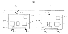
- FIG. 6(a) shows a state during normal running as an example of the electric vehicle of this embodiment.
- Electric power from the overhead wire 1 is input to the power controller PC via the pantograph PT, and the motor MT is driven by the output from the power controller PC.
- MT functions as a regenerative power generator, power is converted by the power controller PC, and the regenerated power is supplied to the overhead line 1 from the pantograph PT.
- the pantograph PT is moved away from the overhead wire 1 when the overhead wire voltage supplied to the electric train or the circuit voltage in the electric train deviates from the specified range, and power is exchanged with the overhead wire. is released.
- a power detection sensor (not shown) measures the overhead wire voltage supplied to the electric car or the circuit voltage in the electric car, and when the controller CT determines that it deviates from a predetermined range, the pantograph PT is turned on. 1 is issued, and the pantograph PT is separated from the overhead wire 1.
- the battery BAT is not limited to static means, but also includes a case where power is supplied by a dynamic means such as an engine or an auxiliary generator.
- the motor MT is not limited to being installed close to or integrated with the wheels and tires, and may be mounted on the vehicle body of the electric vehicle and drive the wheels and tires via the drive train. Of course it is included.
- detachment on the up line is necessary mainly when the overhead line voltage supplied to the electric car or the circuit voltage inside the electric car deviates below the specified range.
- the electric car in order to stabilize the system and prevent deterioration of the operating performance of the electric car due to power shortage, the electric car is electrically disconnected from the overhead wire. As a result, the overhead line voltage can be restored, and the stability of the system can be restored.
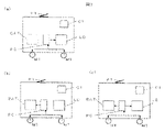
- the motor MT functions as a generator, and regenerative braking works by being consumed by the load LD via the power controller PC.
- the pantograph PT is moved away from the overhead wire 1, and even in a state in which power exchange with the overhead wire is cancelled, regeneration is possible. It becomes possible to effectively function the brake.
- FIG. 7(b) is a diagram showing that instead of the load LD in FIG. 7(a), power is converted by the power controller PC, and the regenerative brake is activated by charging the battery BAT. In this case, the charged electric power can be effectively used when going up, realizing effective use of electric power.
- FIG. 7(c) is a diagram showing an example in which the power controller PC appropriately distributes power between the load LD and the battery BAT depending on the situation.
- the power controller PC appropriately distributes power between the load LD and the battery BAT depending on the situation.
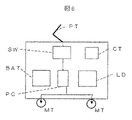
- FIG. 8 is a diagram corresponding to FIG. 6(a). The difference is that a switching device SW is provided between the pantograph PT and the power controller PC. As a result, without physically separating the pantograph PT from the overhead wire 1 as shown in FIG. do.
- the operation of the switchgear SW is smaller than the pantograph PT, and the distance between the contacts in the switchgear SW is smaller than the distance between the pantograph PT and the overhead wire 1, so the operation is almost instantaneous. can be reconnected to.
- the reconnection causes the overhead wire voltage to fluctuate after reconnection, and if the reconnection deviates from the range determined by the reconnection, it is desirable to disconnect again in a short period of time.
- Employment of the switchgear SW is effective in stabilizing the electric vehicle system as a whole, because it realizes a high-speed ON/OFF of the power supply connection.
- the switchgear SW may be provided with a plurality of systems with different current values by means of a current reduction resistance or the like, and these systems may be turned on sequentially. This is because the electrical connection with the overhead line 1 can be made stepwise, and the reconnection can be performed while checking the electrical stability and influence of the system at the time of reconnection. Further, the plurality of systems may be connected only by systems having no current reduction resistance after ensuring stable connection. This is because, in this case, power consumption due to the current reduction resistance can be suppressed.
- the switchgear SW is not limited to a mechanical switchgear, but also includes a semiconductor switchgear.
- FIG. 9 is a diagram corresponding to FIG. 6(b), showing a state in which the switching device SW is turned off instead of lowering the pantograph PT, and the motor MT is driven by the power from the battery BAT.
- FIG. 10 is a diagram corresponding to FIG. 7(a), in which the motor MT functions as a generator during descent, and the power is supplied from the power controller PC to the load LD and consumed by the load LD for regeneration. It is the figure which showed the state which functions as a brake.
- the power from the motor MT may be charged in the battery BAT or distributed to the battery BAT and the load LD by the power controller PC, as in FIGS. 7(b) and 7(c).
- FIG. 11 shows the state of going uphill, and when a voltage drop occurs in the overhead wire, by supplementing the insufficient power from the battery BT, continuous and stable uphill climbing, acceleration, and speed maintenance are realized.
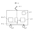
- FIG. 12 shows the state of downhill. Part of the regenerative power is consumed by the load LD, or the battery BAT is partially charged and the rest is returned to the overhead line as regenerative power. A rise can be suppressed, and deviation from the defined voltage range can be suppressed.
- This detachment can also be processed in the order of the quickest reaction of each car by the voltage detection sensor on each electric car.
- a certain time weight after digitizing the value detected by the sensor.
- the value of this weight is made different for each electric car, or for a plurality of electric cars.
- the controller CT which controls the electrical system of the vehicle, is set up until the vehicle issues an electrical disconnection processing command from the overhead wire to the pantograph PT, the switchgear SW, or the power controller PC after confirming the deviation with the sensor. Issue the command after waiting for the specified wait time. If the detected value of the sensor returns to the normal range within the wait time, shutting down the entire system will result in excessive shutting down and the overall efficiency will decrease. is confirmed, it is possible to prevent excessive shutdown by stopping the output of the shutdown command.
- Embodiment 4 The major difference between this embodiment and Embodiment 4 is how to set which electric car to cut off from.
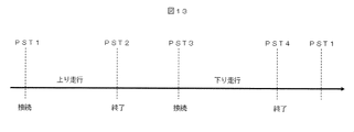
- the horizontal axis shows an image of the running route of the electric vehicle.
- the electric car In the first position PST1, the electric car is connected to the overhead line and begins to travel uphill.
- the uphill stroke ends at the second position PST2.
- transportation, loading and unloading of people, cargo, earth and sand, ore, etc. may be carried out while connected to the overhead wire.
- the overhead wire may be detached and the vehicle may be self-running for transportation, loading and unloading of people, cargo, earth and sand, ore, and the like.
- transportation, loading and unloading of people, cargo, earth and sand, ore, etc. may be performed while being connected to the overhead wire.
- the overhead wire may be removed and the vehicle may be self-sustaining for transportation, loading and unloading of people, cargo, earth and sand, ore, and the like.
- the points of entry into the main overhead wires are specified as PST1 and PST3. You may specify and instruct at times. Having received the instruction, the electric car sets the controller CT of its own car to be a detachment target, and starts constant monitoring of the voltage at the sensor. Alternatively, the central center CC may instruct the electric trains to prioritize the departure process when passing through the PST. As a result, the electric vehicle can set a shorter time wait in the fourth embodiment as the instructed priority is higher.
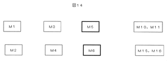
- Embodiments 4 and 5 The major difference between this embodiment and Embodiments 4 and 5 is the method of setting which electric car to cut off from.
- the electric cars to be cut off are specified in advance.
- Embodiments 4 and 5 The major difference between this embodiment and Embodiments 4 and 5 is the method of setting which electric car to cut off from.
- each electric car the controller CT on the car and the central center CC are connected by wireless communication, and the voltage values detected by the sensors of each electric car are communicated to the central center CC at any time.
- the central center CC judges the state of the voltage, determines the electric car to leave, and issues a departure command to the electric car.
- An electric car that has received a detachment command cuts off the electrical connection with the overhead wire, and the entire electric system deviates from the specified range or recovers from the deviance tendency.
- the central center CC considers one or more of the position, speed, slope, topography of the destination, etc. of each electric car when deciding which electric car to issue a detachment command, and determines whether the performance of the electric car will be degraded. It is also desirable to determine the electric vehicles to which the detachment command is issued in the order of difficulty of occurrence or the order of efficiency in stabilizing the system. In this case, more efficient operation of the electric vehicle group is realized.
- each electric car is equipped with a position specifying means such as GPS, and the relevant information is collected at the central center CC, and the electric car that issues the departure command is decided. It can be used when This is because highly accurate information can be easily secured.
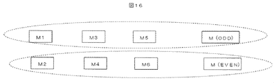
- Embodiment 7 The major difference between this embodiment and Embodiment 7 is how to set which electric car to cut off from.
- FIG. 15 The concept of this embodiment is shown in FIG.
- the central center CC and each electric car corresponded 1:1, but in this embodiment, as shown in FIG.
- M EVEN
- M communicates with each other by radio communication within each group, and determines an electric car to leave independently in each group.
- a good wireless communication environment can be maintained, resulting in a delay in the decision to leave due to communication failure. can be avoided.
- this embodiment can be said to be an autonomous decentralized control type.
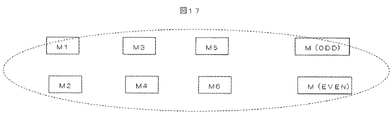
- the major difference between this embodiment and the eighth embodiment is how to set which electric car to cut off from.
- each group is configured for uplink and downlink, but in this embodiment, a group is configured as a whole.
- the major difference between this embodiment and the eighth embodiment is how to set which electric car to cut off from.
- FIG. 1 The concept of this embodiment is shown in FIG.
- the inbound and outbound trains are not separated, but adjacent electric cars are grouped together.
- the number of electric cars belonging to a group is reduced within the same up line or down line, but it has the advantage of being able to cope with poor wireless communication environments.
- the electric train when the voltage of the circuit of the electric train connected to the power line deviates from a predetermined range for a predetermined confirmation time or longer, the electric train is disconnected from the power line. Furthermore, it is characterized in that the easiness of parallel disconnection is differentiated between power running and deceleration/braking.
- the confirmation time during power running is set longer than the confirmation time during speed control/braking. Conversely, regarding the confirmation time when the circuit voltage deviates from the lower limit of the predetermined range, the confirmation time during deceleration/braking is made longer than the confirmation time during power running.
- the powering vehicle has a longer parallel-disconnection confirmation time than the speed-reducing/braking vehicle, ⁇ Make sure that the parallel-disconnection confirmation time is longer for the braking vehicle.
- the electric car controller CT or the like determines whether the electric car is running, that is, whether it is a power running state or a deceleration/braking state.
- each electric car can separate from the power line in the direction of stabilization. Processing becomes possible, and stable operation of the entire electric vehicle system is realized.
- the difference between the present embodiment and the eleventh embodiment is that a different mechanism from the eleventh embodiment is used as a mechanism for differentiating the ease of disconnection.
- a certain range and voltage deviation level of the circuit voltage is used during power running and speed control/braking. It makes a difference.
- a certain range of circuit voltage during power running is made higher than that during speed reduction/braking.
- the controller CT or the like of the electric car judges whether the running state of the electric car, that is, the power running state or the speed control/braking state, and depending on the judgment result, the range of the circuit voltage is set to The power running state>the speed control/braking state.
- each electric car can separate from the power line in the direction of stabilization. Processing becomes possible, and stable operation of the entire electric vehicle system is realized.
Abstract
Description
下り線の電気車M2による電力回生によって、電力線の系全体のエネルギーが増加する。 (2) The reduction in the energy of the entire power line system acts on the side of the power line voltage drop.
Power regeneration by electric car M2 on the down line increases the energy of the entire power line system.
v1=v0-i1×(r11+r12)<v0
ということを意味する。 In terms of equivalent circuit,
v1=v0-i1×(r11+r12)<v0
That means.
v2=v0+i2×(r21+r22)>v0
このため、以下のような問題が生じる。 In terms of equivalent circuit,
v2=v0+i2×(r21+r22)>v0
Therefore, the following problems arise.
(A)電力線に接続された電気車の回路電圧が一定範囲の下限を下回って逸脱したときの場合である。 As shown in Fig. 1, when a plurality of electric cars run on both the inbound line and the outbound line, when the overhead wire voltage supplied to the electric cars or the circuit voltage in the electric cars An example of what happens when the is disconnected from the overhead line is as follows.
(A) This is the case when the circuit voltage of an electric car connected to a power line deviates below the lower limit of a certain range.
(B)電力線に接続された電気車の回路電圧が一定範囲の上限を上回って逸脱したときの場合である。 That is, when the deviation falls below the lower limit, it is necessary to detach the electric train on the up line.
(B) This is the case when the circuit voltage of an electric car connected to a power line deviates beyond the upper limit of a certain range.
(A)抑速・制動状態:高い場合<低い場合、
(B)力行状態:高い場合>低い場合
とすることを意味する。 The electric car controller CT or the like determines whether the electric car is running, that is, whether it is a power running state or a deceleration/braking state. (A) Suppression/braking state: when high < when low,
(B) Powering state: High case > low case.
力行状態>抑速・制動状態
とすることである。 The controller CT or the like of the electric car judges whether the running state of the electric car, that is, the power running state or the speed control/braking state, and depending on the judgment result, the range of the circuit voltage is set to
The power running state>the speed control/braking state.
1A 上り側の高電圧側電力線
2A 下り側の高電圧側電力線
1B 上り側の低電圧側電力線
2B 下り側の低電圧側電力線
PT、PT1、PT2 パンタグラフ(集電装置)
M 電気車
M1 上り線の電気車
M2 下り線の電気車
RD1,RD2 路面
50 勾配
PS 電源
CT コントローラ
BAT バッテリー(電源装置)
PC パワーコントローラ
LD 負荷
MT モータ
SW 開閉装置
CC 中央センタ 1 overhead line 1A high-voltage power line 2A on the downstream side high-voltage power line 1B on the downstream side low-voltage power line 2B on the downstream side low-voltage power lines PT, PT1, PT2 on the downstream side pantograph (current collector)
M Electric car M1 Up line electric car M2 Down line electric cars RD1,
PC Power controller LD Load MT Motor SW Switchgear CC Central center
Claims (10)
- 集電装置を介して電力線から得た電力、もしくは、自車に搭載したエネルギー源、もしくは、その両方の併用によって駆動するとともに、制動時等に発生する電力を、集電装置を介して電力線に回生する、もしくは、自車に搭載した負荷で消費する電気車であって、
前記電力線の電圧、あるいは電気車内の回路電圧が定められた範囲を逸脱した際に、前記集電装置を前記電力線から電気的に離間する機能を有することを特徴とする電気車。 It is driven by power obtained from the power line via a current collector, or an energy source installed in the vehicle, or a combination of both, and the power generated during braking, etc. An electric car that regenerates or consumes with the load mounted on the car,
An electric car having a function of electrically separating the current collector from the power line when the voltage of the power line or the circuit voltage in the electric car deviates from a predetermined range. - 前記電気的に離間する機能は、機械的集電装置と前記電力線との距離離間により行われることを特徴とする請求項1記載の電気車。 The electric car according to claim 1, wherein the function of electrically separating is performed by separating a mechanical current collector and the power line.
- 前記電気的に離間する機能は、電気車に積載された開閉装置により行われることを特徴とする請求項1記載の電気車。 The electric vehicle according to claim 1, wherein the function of electrically separating is performed by a switching device mounted on the electric vehicle.
- 前記、電力線の電圧、あるいは電気車内の回路電圧が定められた範囲を逸脱した際の判定は、電気車に搭載されたセンサに基づき行われ、このセンサの反応速度は電気車に対し設定可能であることを特徴とする請求項1ないし3のいずれか1項に記載の電気車。 The judgment when the voltage of the power line or the circuit voltage in the electric train deviates from a predetermined range is made based on the sensor mounted on the electric train, and the reaction speed of this sensor can be set for the electric train. 4. The electric vehicle according to any one of claims 1 to 3, characterized in that:
- 前記設定は、外部のセンタから電気車に対し設定可能であることを特徴とする請求項4記載の電気車。 The electric vehicle according to claim 4, characterized in that the setting can be made for the electric vehicle from an external center.
- 前記、電力線の電圧、あるいは電気車内の回路電圧が定められた範囲を逸脱した際の判定は、電気車に搭載されたセンサに基づき行われ、当該センサの情報に基づき、外部のセンタが電気車に対し前記電力線から電気的に離間する機能の実行を指示することを特徴とする請求項1ないし3のいずれか1項に記載の電気車。 The determination when the voltage of the power line or the circuit voltage in the electric train deviates from a predetermined range is made based on the sensor mounted on the electric train, and based on the information of the sensor, the external center determines whether the electric train 4. The electric car according to any one of claims 1 to 3, wherein the electric car according to any one of claims 1 to 3 is instructed to execute a function of electrically separating from the power line.
- 前記、電力線の電圧、あるいは電気車内の回路電圧が定められた範囲を逸脱した際の判定は、電気車に搭載されたセンサに基づき行われ、当該センサの情報に基づき、電気車群内での無線相互通信により、前記電力線から電気的に離間する機能を実行する電気車が決定されることを特徴とする請求項1ないし3のいずれか1項に記載の電気車。 The determination when the voltage of the power line or the circuit voltage in the electric car deviates from the specified range is made based on the sensor mounted on the electric car, and based on the information of the sensor, the electric car group 4. Electric vehicle according to any one of claims 1 to 3, characterized in that wireless intercommunication determines which electric vehicle performs the function of electrically decoupling from the power line.
- 前記電気車は、その走行状態、すなわち、力行状態か、抑速・制動状態かを判断するコントローラを有し、
前記集電装置を前記電力線から電気的に離間する機能の実行までの解列確認時間の長さを、回路電圧が一定範囲より、
(A)抑速・制動状態:高い場合<低い場合、
(B)力行状態:高い場合>低い場合
とすることを特徴とする請求項1ないし3のいずれか1項に記載の電気車。 The electric vehicle has a controller that determines its running state, that is, whether it is a power running state or a deceleration/braking state,
The length of the disconnection confirmation time until the execution of the function of electrically separating the current collector from the power line is determined from the constant range of the circuit voltage to
(A) Suppression/braking state: when high < when low,
4. The electric vehicle according to any one of claims 1 to 3, wherein (B) powering state: high>low. - 前記電気車は、その走行状態、すなわち、力行状態か、抑速・制動状態かを判断するコントローラを有し、
前記電力線の電圧、あるいは電気車内の回路電圧が定められた範囲の電圧レンジを、
力行状態>抑速・制動状態
とすることを特徴とする請求項1ないし3のいずれか1項に記載の電気車。 The electric vehicle has a controller that determines its running state, that is, whether it is a power running state or a deceleration/braking state,
The voltage range in which the voltage of the power line or the circuit voltage in the electric train is determined,
4. The electric vehicle according to any one of claims 1 to 3, wherein power running state > speed control/braking state. - 請求項1ないし9のいずれか1項に記載の電気車により運用される電気車システム。 An electric vehicle system operated by the electric vehicle according to any one of claims 1 to 9.
Priority Applications (4)
| Application Number | Priority Date | Filing Date | Title |
|---|---|---|---|
| AU2021438215A AU2021438215A1 (en) | 2021-03-29 | 2021-03-29 | Electric vehicle and electric vehicle system |
| EP21934746.5A EP4316899A1 (en) | 2021-03-29 | 2021-03-29 | Electric vehicle and electric vehicle system |
| JP2023509884A JP7441374B2 (en) | 2021-03-29 | 2021-03-29 | Electric vehicles and electric vehicle systems |
| PCT/JP2021/013172 WO2022208569A1 (en) | 2021-03-29 | 2021-03-29 | Electric vehicle and electric vehicle system |
Applications Claiming Priority (1)
| Application Number | Priority Date | Filing Date | Title |
|---|---|---|---|
| PCT/JP2021/013172 WO2022208569A1 (en) | 2021-03-29 | 2021-03-29 | Electric vehicle and electric vehicle system |
Publications (1)
| Publication Number | Publication Date |
|---|---|
| WO2022208569A1 true WO2022208569A1 (en) | 2022-10-06 |
Family
ID=83455686
Family Applications (1)
| Application Number | Title | Priority Date | Filing Date |
|---|---|---|---|
| PCT/JP2021/013172 WO2022208569A1 (en) | 2021-03-29 | 2021-03-29 | Electric vehicle and electric vehicle system |
Country Status (4)
| Country | Link |
|---|---|
| EP (1) | EP4316899A1 (en) |
| JP (1) | JP7441374B2 (en) |
| AU (1) | AU2021438215A1 (en) |
| WO (1) | WO2022208569A1 (en) |
Citations (7)
| Publication number | Priority date | Publication date | Assignee | Title |
|---|---|---|---|---|
| JP2008253084A (en) * | 2007-03-30 | 2008-10-16 | Railway Technical Res Inst | Hybrid power supply system |
| JP2012040954A (en) * | 2010-08-19 | 2012-03-01 | Toshiba Corp | System for supplying electric power for electric railroad |
| JP2013017315A (en) | 2011-07-04 | 2013-01-24 | Hitachi Constr Mach Co Ltd | Electrically driven dump truck |
| JP2014064398A (en) * | 2012-09-21 | 2014-04-10 | Kyushu Railway Co | Electric power system for electric motor vehicle, and electric power supply control method |
| US20150090554A1 (en) * | 2013-09-27 | 2015-04-02 | Siemens Industry, Inc. | System and Method for All Electrical Operation of a Mining Haul Truck |
| JP2018038217A (en) * | 2016-09-02 | 2018-03-08 | 東日本旅客鉄道株式会社 | Ground fault detection system of railway vehicle |
| EP3556594A1 (en) * | 2018-04-17 | 2019-10-23 | Siemens Mobility GmbH | Vehicle and method for operating a vehicle |
-
2021
- 2021-03-29 EP EP21934746.5A patent/EP4316899A1/en active Pending
- 2021-03-29 JP JP2023509884A patent/JP7441374B2/en active Active
- 2021-03-29 AU AU2021438215A patent/AU2021438215A1/en active Pending
- 2021-03-29 WO PCT/JP2021/013172 patent/WO2022208569A1/en active Application Filing
Patent Citations (7)
| Publication number | Priority date | Publication date | Assignee | Title |
|---|---|---|---|---|
| JP2008253084A (en) * | 2007-03-30 | 2008-10-16 | Railway Technical Res Inst | Hybrid power supply system |
| JP2012040954A (en) * | 2010-08-19 | 2012-03-01 | Toshiba Corp | System for supplying electric power for electric railroad |
| JP2013017315A (en) | 2011-07-04 | 2013-01-24 | Hitachi Constr Mach Co Ltd | Electrically driven dump truck |
| JP2014064398A (en) * | 2012-09-21 | 2014-04-10 | Kyushu Railway Co | Electric power system for electric motor vehicle, and electric power supply control method |
| US20150090554A1 (en) * | 2013-09-27 | 2015-04-02 | Siemens Industry, Inc. | System and Method for All Electrical Operation of a Mining Haul Truck |
| JP2018038217A (en) * | 2016-09-02 | 2018-03-08 | 東日本旅客鉄道株式会社 | Ground fault detection system of railway vehicle |
| EP3556594A1 (en) * | 2018-04-17 | 2019-10-23 | Siemens Mobility GmbH | Vehicle and method for operating a vehicle |
Also Published As
| Publication number | Publication date |
|---|---|
| JPWO2022208569A1 (en) | 2022-10-06 |
| EP4316899A1 (en) | 2024-02-07 |
| AU2021438215A1 (en) | 2023-10-05 |
| JP7441374B2 (en) | 2024-02-29 |
Similar Documents
| Publication | Publication Date | Title |
|---|---|---|
| JP4476917B2 (en) | Battery-powered railway train | |
| JP5452371B2 (en) | Railway vehicle drive system | |
| JP4440936B2 (en) | Electric vehicle control device | |
| EP2476573B1 (en) | Energy management system for trains with flexible formations incorporating regenerative braking | |
| US9731616B2 (en) | Railway vehicle system | |
| JP4747204B2 (en) | Railway system with power supply equipment on the railway line between stations | |
| US20200207377A1 (en) | Railway power system and associated method | |
| WO2014106164A1 (en) | A battery-powered all-electric and/or hybrid locomotive and related locomotive and train configurations | |
| JP6055258B2 (en) | Railway vehicle | |
| US20200207376A1 (en) | Power system and associated method | |
| JP5851925B2 (en) | Electric railway vehicle drive system | |
| WO2022208569A1 (en) | Electric vehicle and electric vehicle system | |
| JP2003220859A (en) | Power accumulation unit for dc electrical equipment and railway electrical system | |
| JP6259778B2 (en) | Railway vehicle drive system | |
| US20240149705A1 (en) | Electric Vehicle and Electric Vehicle System | |
| JP2001320831A (en) | Electric rolling stock for railway | |
| JP2016158375A (en) | Battery drive system and battery drive method | |
| WO2022091886A1 (en) | Power supply system for electric vehicle, and power supply equipment | |
| CN103448736A (en) | Unmanned electric locomotive | |
| CN117601658A (en) | Magnetic levitation train braking control method and system |
Legal Events
| Date | Code | Title | Description |
|---|---|---|---|
| 121 | Ep: the epo has been informed by wipo that ep was designated in this application |
Ref document number: 21934746 Country of ref document: EP Kind code of ref document: A1 |
|
| ENP | Entry into the national phase |
Ref document number: 2023509884 Country of ref document: JP Kind code of ref document: A |
|
| WWE | Wipo information: entry into national phase |
Ref document number: 18281415 Country of ref document: US |
|
| WWE | Wipo information: entry into national phase |
Ref document number: 2021438215 Country of ref document: AU Ref document number: AU2021438215 Country of ref document: AU |
|
| ENP | Entry into the national phase |
Ref document number: 2021438215 Country of ref document: AU Date of ref document: 20210329 Kind code of ref document: A |
|
| WWE | Wipo information: entry into national phase |
Ref document number: 2021934746 Country of ref document: EP |
|
| NENP | Non-entry into the national phase |
Ref country code: DE |
|
| ENP | Entry into the national phase |
Ref document number: 2021934746 Country of ref document: EP Effective date: 20231030 |