WO2022202746A1 - 対向ピストンエンジン - Google Patents
対向ピストンエンジン Download PDFInfo
- Publication number
- WO2022202746A1 WO2022202746A1 PCT/JP2022/012971 JP2022012971W WO2022202746A1 WO 2022202746 A1 WO2022202746 A1 WO 2022202746A1 JP 2022012971 W JP2022012971 W JP 2022012971W WO 2022202746 A1 WO2022202746 A1 WO 2022202746A1
- Authority
- WO
- WIPO (PCT)
- Prior art keywords
- piston
- fuel injection
- outer peripheral
- cylinder
- groove
- Prior art date
- Legal status (The legal status is an assumption and is not a legal conclusion. Google has not performed a legal analysis and makes no representation as to the accuracy of the status listed.)
- Ceased
Links
Images





Classifications
-
- F—MECHANICAL ENGINEERING; LIGHTING; HEATING; WEAPONS; BLASTING
- F02—COMBUSTION ENGINES; HOT-GAS OR COMBUSTION-PRODUCT ENGINE PLANTS
- F02B—INTERNAL-COMBUSTION PISTON ENGINES; COMBUSTION ENGINES IN GENERAL
- F02B75/00—Other engines
- F02B75/28—Engines with two or more pistons reciprocating within same cylinder or within essentially coaxial cylinders
-
- F—MECHANICAL ENGINEERING; LIGHTING; HEATING; WEAPONS; BLASTING
- F02—COMBUSTION ENGINES; HOT-GAS OR COMBUSTION-PRODUCT ENGINE PLANTS
- F02B—INTERNAL-COMBUSTION PISTON ENGINES; COMBUSTION ENGINES IN GENERAL
- F02B23/00—Other engines characterised by special shape or construction of combustion chambers to improve operation
- F02B23/02—Other engines characterised by special shape or construction of combustion chambers to improve operation with compression ignition
- F02B23/06—Other engines characterised by special shape or construction of combustion chambers to improve operation with compression ignition the combustion space being arranged in working piston
-
- F—MECHANICAL ENGINEERING; LIGHTING; HEATING; WEAPONS; BLASTING
- F02—COMBUSTION ENGINES; HOT-GAS OR COMBUSTION-PRODUCT ENGINE PLANTS
- F02B—INTERNAL-COMBUSTION PISTON ENGINES; COMBUSTION ENGINES IN GENERAL
- F02B23/00—Other engines characterised by special shape or construction of combustion chambers to improve operation
- F02B23/08—Other engines characterised by special shape or construction of combustion chambers to improve operation with positive ignition
- F02B23/10—Other engines characterised by special shape or construction of combustion chambers to improve operation with positive ignition with separate admission of air and fuel into cylinder
-
- F—MECHANICAL ENGINEERING; LIGHTING; HEATING; WEAPONS; BLASTING
- F02—COMBUSTION ENGINES; HOT-GAS OR COMBUSTION-PRODUCT ENGINE PLANTS
- F02B—INTERNAL-COMBUSTION PISTON ENGINES; COMBUSTION ENGINES IN GENERAL
- F02B25/00—Engines characterised by using fresh charge for scavenging cylinders
- F02B25/02—Engines characterised by using fresh charge for scavenging cylinders using unidirectional scavenging
- F02B25/08—Engines with oppositely-moving reciprocating working pistons
-
- F—MECHANICAL ENGINEERING; LIGHTING; HEATING; WEAPONS; BLASTING
- F02—COMBUSTION ENGINES; HOT-GAS OR COMBUSTION-PRODUCT ENGINE PLANTS
- F02B—INTERNAL-COMBUSTION PISTON ENGINES; COMBUSTION ENGINES IN GENERAL
- F02B75/00—Other engines
- F02B75/28—Engines with two or more pistons reciprocating within same cylinder or within essentially coaxial cylinders
- F02B75/282—Engines with two or more pistons reciprocating within same cylinder or within essentially coaxial cylinders the pistons having equal strokes
-
- F—MECHANICAL ENGINEERING; LIGHTING; HEATING; WEAPONS; BLASTING
- F02—COMBUSTION ENGINES; HOT-GAS OR COMBUSTION-PRODUCT ENGINE PLANTS
- F02F—CYLINDERS, PISTONS OR CASINGS, FOR COMBUSTION ENGINES; ARRANGEMENTS OF SEALINGS IN COMBUSTION ENGINES
- F02F1/00—Cylinders; Cylinder heads
-
- F—MECHANICAL ENGINEERING; LIGHTING; HEATING; WEAPONS; BLASTING
- F02—COMBUSTION ENGINES; HOT-GAS OR COMBUSTION-PRODUCT ENGINE PLANTS
- F02F—CYLINDERS, PISTONS OR CASINGS, FOR COMBUSTION ENGINES; ARRANGEMENTS OF SEALINGS IN COMBUSTION ENGINES
- F02F3/00—Pistons
- F02F3/26—Pistons having combustion chamber in piston head
-
- F—MECHANICAL ENGINEERING; LIGHTING; HEATING; WEAPONS; BLASTING
- F02—COMBUSTION ENGINES; HOT-GAS OR COMBUSTION-PRODUCT ENGINE PLANTS
- F02M—SUPPLYING COMBUSTION ENGINES IN GENERAL WITH COMBUSTIBLE MIXTURES OR CONSTITUENTS THEREOF
- F02M61/00—Fuel-injectors not provided for in groups F02M39/00 - F02M57/00 or F02M67/00
- F02M61/14—Arrangements of injectors with respect to engines; Mounting of injectors
-
- Y—GENERAL TAGGING OF NEW TECHNOLOGICAL DEVELOPMENTS; GENERAL TAGGING OF CROSS-SECTIONAL TECHNOLOGIES SPANNING OVER SEVERAL SECTIONS OF THE IPC; TECHNICAL SUBJECTS COVERED BY FORMER USPC CROSS-REFERENCE ART COLLECTIONS [XRACs] AND DIGESTS
- Y02—TECHNOLOGIES OR APPLICATIONS FOR MITIGATION OR ADAPTATION AGAINST CLIMATE CHANGE
- Y02T—CLIMATE CHANGE MITIGATION TECHNOLOGIES RELATED TO TRANSPORTATION
- Y02T10/00—Road transport of goods or passengers
- Y02T10/10—Internal combustion engine [ICE] based vehicles
- Y02T10/12—Improving ICE efficiencies
Definitions
- the present disclosure relates to opposed-piston engines.
- This application claims priority based on Japanese Patent Application No. 2021-053560 filed with the Japan Patent Office on March 26, 2021, the content of which is incorporated herein.
- Two-stroke diesel engines include opposed-piston engines in which two pistons are arranged inside one cylinder to face each other and a combustion chamber is formed between the two pistons (for example, Patent Document 1).
- the opposed-piston engine has an exhaust stroke in which the combustion gas in the cylinder is discharged from the exhaust port formed in the cylinder wall during one reciprocation of the piston, and a scavenging stroke in which air is taken into the cylinder from the scavenging port formed in the cylinder wall. and are performed.
- the scavenging port formed in the cylinder wall is inclined to form a swirl flow in the air taken in from the scavenging port, thereby enhancing the effect of exchanging scavenging air and exhaust gas.
- Patent Document 1 by adopting a spiral injection structure for the injection hole for injecting fuel into the inside of the cylinder, the interference of the spray injected from the injector is suppressed, and the amount of heat transfer to the piston and cylinder wall is reduced. Inventions aimed at minimizing are disclosed.
- fuel is injected from a fuel injection device provided on the cylinder wall.
- the fuel injected into the cylinder may be swirled by the swirl flow formed in the cylinder and burned in the outer peripheral region of the combustion chamber.
- the spread of the combustion flame to the outer peripheral region of the combustion chamber may increase the heat load on the outer peripheral portion of the piston to which the cooling effect from the inside of the piston is difficult to reach.
- An increase in the thermal load on the outer periphery of the piston may cause problems such as poor sliding of the piston due to deterioration of piston lubrication (deterioration of lubricating oil) and damage to the piston due to thermal stress generated in the piston.
- the piston described in Patent Document 1 has a short distance from the outer peripheral edge of the cavity formed on the top surface of the piston to the outer peripheral edge of the top surface, and the heat of the combustion flame in the cavity easily reaches the outer peripheral portion of the piston. Therefore, the heat load on the outer peripheral portion of the piston may increase.
- an object of at least one embodiment of the present disclosure is to provide an opposed-piston engine capable of reducing the heat load on the outer periphery of the piston.
- An opposed-piston engine includes: a cylinder; a one-side piston arranged on one side in the axial direction inside the cylinder; a second side piston disposed on the other side in the axial direction inside the cylinder, A one-side cavity recessed toward the center is formed on the top surface of the one-side piston, The top surface of the other side piston is formed with the other side cavity recessed toward the center, When the diameter of the top surface of the one-side piston is D1, the outer peripheral edge of the one-side cavity is separated from the outer peripheral edge of the top surface of the one-side piston by 0.1D1 or more over the entire circumference. , When the diameter of the top surface of the other side piston is D2, the outer peripheral edge of the other side cavity is separated from the outer peripheral edge of the top surface of the other side piston by 0.1D2 or more over the entire circumference. .
- an opposed-piston engine capable of reducing the heat load on the outer periphery of the piston.
- FIG. 1 is a schematic cross-sectional view schematically showing the configuration of an opposed-piston engine according to an embodiment of the present disclosure
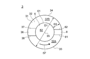
- FIG. FIG. 4 is a schematic front view of the one-side piston, schematically showing a state in which the top surface of the one-side piston is viewed from the front in the embodiment of the present disclosure
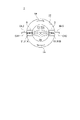
- FIG. 4 is a schematic front view of the other-side piston, schematically showing a top surface of the other-side piston viewed from the front in an embodiment of the present disclosure
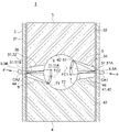
- FIG. 2 is a schematic cross-sectional view schematically showing a cross section along the axial direction near the combustion chamber of the opposed piston according to the embodiment of the present disclosure; It is an explanatory view for explaining positional relationship of one side fuel injection groove, the other side fuel injection groove, the one side fuel injection device, and the other side fuel injection device.
- FIG. 4 is an explanatory diagram for explaining a one-side fuel injection groove in one embodiment of the present disclosure
- FIG. 5 is an explanatory diagram for explaining one-side fuel injection grooves according to a comparative example
- FIG. 5 is an explanatory diagram for explaining the other side fuel injection groove in the embodiment of the present disclosure
- FIG. 4 is an explanatory diagram for explaining a scavenging port according to an embodiment of the present disclosure
- FIG. FIG. 4 is an explanatory diagram for explaining an exhaust port according to an embodiment of the present disclosure
- expressions that express shapes such as squares and cylinders do not only represent shapes such as squares and cylinders in a geometrically strict sense, but also include irregularities and chamfers to the extent that the same effect can be obtained.
- the shape including the part etc. shall also be represented.
- the expressions “comprising”, “including”, or “having” one component are not exclusive expressions excluding the presence of other components.
- symbol may be attached
- FIG. 1 is a schematic cross-sectional view schematically showing the configuration of an opposed-piston engine according to one embodiment of the present disclosure.
- an opposed-piston engine 1 includes a cylinder 2 in which a cylinder bore 21 extending along the axial direction (vertical direction in the figure) is formed, and A one-side piston 3 arranged on one side (upper side in the figure) in the axial direction inside the cylinder 2, and a other-side piston 4 arranged on the other side (lower side in the figure) in the axial direction inside the cylinder 2, Prepare.
- the other side piston 4 is arranged on the opposite side of the one side piston 3 in the axial direction of the cylinder 2 .
- the cylinder 2 has an inner surface 22 forming a cylinder bore 21 .
- At least one (a plurality of in the illustrated example) scavenging ports 23 are formed in the inner surface 22 on one side of the cylinder 2 in the axial direction.
- At least one (a plurality of in the illustrated example) exhaust ports 24 are formed in the inner surface 22 on the other axial side of the cylinder 2 .
- a plurality of scavenging ports 23 are provided at intervals in the circumferential direction of the cylinder 2 .
- the plurality of exhaust ports 24 are provided at intervals in the circumferential direction of the cylinder 2 .
- Each of the plurality of scavenging ports 23 guides the combustion gas CG (compressed air in the illustrated example) from the outside to the inside of the cylinder 2 in a direction inclined to one side in the circumferential direction with respect to the radial direction of the cylinder 2. It has a shape. In one embodiment, each of the plurality of scavenging ports 23 extends in a direction inclined at a predetermined angle to one side in the circumferential direction with respect to the radial direction of the cylinder 2 .
- the combustion gas CG (scavenging air) guided into the cylinder 2 (that is, the cylinder bore 21 ) through the scavenging port 23 forms a swirl flow SF (swirling flow) inside the cylinder 2 .
- the combustion gas CG guided into the cylinder 2 through the scavenging port 23 flows to the exhaust side while swirling.
- the swirl flow SF inside the cylinder 2
- the effect of exchanging the scavenging air and the exhaust air in the cylinder bore 21 can be enhanced in the scavenging process and the exhaust process.
- the one-side piston 3 is arranged on the scavenging side where the scavenging port 23 is formed in the axial direction of the cylinder 2 .
- the other side piston 4 is arranged on the exhaust side where the exhaust port 24 is formed in the axial direction of the cylinder 2 . That is, the one-side piston 3 consists of a scavenging-side piston 3A, and the other-side piston 4 consists of an exhaust-side piston 4A.
- the one-side piston 3 may be the scavenging-side piston 3A or the exhaust-side piston 4A.
- the other side piston 4 may be the exhaust side piston 4A or the scavenging side piston 3A.
- the one-side piston 3 and the other-side piston 4 are each arranged in a cylinder bore 21 so as to be able to reciprocate along the axial direction of the cylinder 2 .
- a combustion chamber 11 is formed between a top surface 31 of the one-side piston 3 and a top surface 41 of the other-side piston 4 in the cylinder bore 21 .
- the top surface 31 of the one-side piston 3 faces the top surface 41 of the other-side piston 4 with the combustion chamber 11 interposed therebetween.
- the one-side piston 3 and the other-side piston 4 at the bottom dead center are indicated by solid lines, and the top surface 31 of the one-side piston 3 at the top dead center and the top surface 41 of the other-side piston 4 at the top dead center. are indicated by two-dot chain lines.
- the one-side piston 3 and the other-side piston 4 reciprocate inside the cylinder 2 in synchronization with each other.
- the one-side piston 3 reaches the top dead center (the position closest to the other-side piston 4) when the other-side piston 4 reaches the top dead center (the position closest to the other side piston 3). position).
- the one-side piston 3 reaches the bottom dead center (the position farthest from the other-side piston 4) when the other-side piston 4 reaches the bottom dead center (the position farthest from the one-side piston 3).
- the one-side piston 3 and the other-side piston 4 may reach the top dead center or the bottom dead center at different times.
- the one-side piston 3 is connected to one end of the one-side connecting rod 14 via the one-side piston pin 12, and the other end of the one-side connecting rod 14 is connected to the crank. It is connected to shaft 16 .
- the other side piston 4 is connected to one end of the other side connecting rod 15 via the other side piston pin 13 , and the other end of the other side connecting rod 15 is connected to the crankshaft 16 .
- the opposed-piston engine as shown in FIG. valve 5 5.
- the fuel injection device 5 is provided on the inner surface 22 of the cylinder 2 .
- the fuel injection device 5 has at least one injection hole 51 for injecting the fuel F into the cylinder bore 21 .
- the fuel injection device 5 injects the fuel F into the cylinder bore when the crank angle (the rotation angle of the crankshaft 16) reaches a predetermined angle (for example, when the one-side piston 3 or the other-side piston 4 reaches the top dead center). 21 to inject.
- the opposed-piston engine 1 compresses and heats the combustion gas CG introduced into the cylinder 2 through the scavenging port 23 by the one-side piston 3 and the other-side piston 4 to a temperature higher than the ignition point of the fuel F.
- the fuel F By injecting the fuel F from the fuel injection device 5 into the compressed and heated combustion gas CG, the fuel F is self-ignited. A combustion flame is formed by self-ignition of the fuel F.
- the one-side piston 3 and the other-side piston 4 are pushed away from each other due to the expansion of combustion gas caused by self-ignition.
- the reciprocating motion of the one-side piston 3 and the other-side piston 4 is transmitted to the crankshaft 16 and converted into rotational force (power) by the crankshaft 16 .
- Each of the plurality of scavenging ports 23 is formed closer to the scavenging side (the one side in the axial direction) than the top surface 31 of the scavenging-side piston 3A at the top dead center, and the top surface 31 of the scavenging-side piston 3A at the bottom dead center. is formed on the exhaust side (the other side in the axial direction).
- Each of the plurality of exhaust ports 24 is formed closer to the exhaust side than the top surface 41 of the exhaust-side piston 4A at the top dead center, and is formed closer to the scavenging side than the top surface 41 of the exhaust-side piston 4A at the bottom dead center.
- the combustion gas CG can be supplied to the cylinder bores 21 through the scavenging ports 23.
- Exhaust gas EG can be discharged from the cylinder bore 21 through each exhaust port 24 by sliding the top surface 41 of the exhaust side piston 4A toward the exhaust side rather than each exhaust port 24 . Since the combustion gas CG supplied to the cylinder bore 21 is compressed by a supercharger (not shown), the pressure difference between the scavenging port 23 and the exhaust port 24 causes the combustion gas CG to be supplied to the cylinder bore 21. and discharge of the exhaust gas EG from the cylinder bore 21 is performed.
- FIG. 2 is a schematic front view of the one-side piston, schematically showing a top surface of the one-side piston viewed from the front in one embodiment of the present disclosure.
- FIG. 3 is a schematic front view of the other-side piston schematically showing a top surface of the other-side piston viewed from the front in an embodiment of the present disclosure.
- FIG. 4 is a schematic cross-sectional view schematically showing a cross-section along the axial direction near the combustion chamber of opposed pistons according to an embodiment of the present disclosure.
- the opposed-piston engine 1 according to some embodiments, as shown in FIG. and a formed other side piston 4 .
- a top surface 31 of the one-side piston 3 is formed with a one-side cavity 6 recessed toward the center.
- a top surface 41 of the other side piston 4 is formed with the other side cavity 7 recessed toward the center.
- the other side cavity 7 faces the one side cavity 6 with the combustion chamber 11 interposed therebetween.
- the top surface 31 of the one-side piston 3 extends from the outer peripheral edge 61 of the one-side cavity 6 toward the outer peripheral side (outside in the radial direction of the cylinder 2). It includes a one-side outer peripheral edge portion 32 that does. An outer peripheral edge 34 of the one-side outer peripheral edge portion 32 (top surface 31 ) continues to one end of an outer peripheral portion 33 of the one-side piston 3 extending along the axial direction of the cylinder 2 .
- the one-side cavity 6 has a concave curved surface 62 whose depth from the outer peripheral edge 61 increases toward the inner side in the radial direction of the cylinder 2 from the outer peripheral edge 61 .
- the diameter of the top surface 31 of the one-side piston 3 is D1
- the distance from the outer peripheral edge 61 of the one-side cavity 6 to the outer peripheral edge 34 of the top surface 31 of the one-side piston 3 is defined as D3.
- the top surface 31 of the one-side piston 3 satisfies the condition of D3 ⁇ 0.1D1 over the entire circumference.
- the outer peripheral edge 61 of the one-side cavity 6 is separated from the outer peripheral edge 34 of the top surface 31 of the one-side piston 3 by 0.1D1 or more over the entire circumference.
- the top surface 41 of the other side piston 4 extends from the outer peripheral edge 71 of the other side cavity 7 toward the outer peripheral side (outside in the radial direction of the cylinder 2).
- the other side outer peripheral edge 42 is included.
- An outer peripheral edge 44 of the other side outer peripheral edge portion 42 (top surface 41 ) continues to one end of an outer peripheral portion 43 of the other side piston 4 extending along the axial direction of the cylinder 2 .
- the other side cavity 7 has a concave curved surface 72 whose depth from the outer peripheral edge 71 increases toward the inner side in the radial direction of the cylinder 2 from the outer peripheral edge 71 .
- the diameter of the top surface 41 of the piston 4 on the other side is D2
- the distance from the outer peripheral edge 71 of the cavity 7 on the other side to the outer peripheral edge 44 of the top surface 41 of the piston 4 on the other side is defined as D4.
- the top surface 41 of the other side piston 4 satisfies the condition of D4 ⁇ 0.1D2 over the entire circumference.
- the outer peripheral edge 71 of the cavity 7 on the other side is separated from the outer peripheral edge 44 of the top surface 41 of the piston 4 on the other side by 0.1D2 or more over the entire circumference.
- the outer peripheral edge 61 of the one-side cavity 6 is provided at a predetermined distance (0.1D1) or more from the outer peripheral edge 34 of the top surface 31 of the one-side piston 3 over the entire circumference
- the outer peripheral edge 71 of the cavity 7 on the other side is provided at a predetermined distance (0.1D2) or more from the outer peripheral edge 44 of the top surface 41 of the piston 4 on the other side over the entire circumference. Therefore, a space for combustion (cavity forming space) 11A is formed at the center of the combustion chamber 11 by the cavity 6 on one side and the cavity 7 on the other side. Combustion can be completed in the combustion space 11A by compressing the combustion gas in the combustion space 11A and injecting the fuel into the combustion space 11A.
- the top surface 31 of the one-side piston 3 preferably satisfies the condition D3 ⁇ 0.2D1 over the entire circumference, and D3 over the entire circumference. More preferably, the condition ⁇ 0.3D1 is satisfied.
- the top surface 41 of the other side piston 4 preferably satisfies the condition D4 ⁇ 0.2D2 over the entire circumference, and D4 over the entire circumference. More preferably, the condition ⁇ 0.3D2 is satisfied.
- the one side cavity 6 and the other side cavity 7 described above are hemispherical.
- the volume of the spherical space 11A for combustion formed at the center of the combustion chamber 11 is secured, and the outer peripheral edges of the one-side cavity 6 and the other-side cavity 7
- the distances D3 and D4 of the pistons 61 and 71 from the outer peripheral edges 34 and 44 of the top surfaces of the one-side piston 3 and the other-side piston 4 can be increased.
- the heat load on the outer peripheral portions 33 and 43 of the one-side piston 3 and the other-side piston 4 can be effectively reduced.
- the above-described one-side piston 3 has an outer peripheral edge 61 of the one-side cavity 6 to an outer peripheral edge 34 of the top surface 31 of the one-side piston 3 .
- a one-side fuel injection groove 8 extending across is formed.
- the other side piston 4 has the other side fuel extending from the outer peripheral edge 71 of the other side cavity 7 to the outer peripheral edge 44 of the top surface 41 of the other side piston 4 .
- a jet groove 9 is formed.
- the one side fuel injection groove 8 and the other side fuel injection groove 9 may be formed so that the groove depth increases toward the inner side in the radial direction.
- the at least one fuel injection device 5 described above includes one side fuel injection device 5A arranged so that the injected fuel passes through the one side fuel injection groove 8, and the other side fuel injection device 5A arranged so that the injected fuel passes through the other side fuel injection groove 9. and the arranged other side fuel injection device 5B.
- FIG. 5 is an explanatory diagram for explaining the positional relationship among the one-side fuel injection groove, the other-side fuel injection groove, the one-side fuel injection device, and the other-side fuel injection device.
- the one-side fuel injection device 5A is arranged such that the injection holes 51A (51) are positioned within the range in which the one-side fuel injection grooves 8 are formed in the circumferential direction of the cylinder 2. there is The one-side fuel injection device 5A is arranged such that a straight line extending from the central axis CA1 passes through the one-side fuel injection groove 8. As shown in FIG.
- the other side fuel injection device 5B is arranged such that the injection hole 51B (51) is positioned within the range in which the other side fuel injection groove 9 is formed in the circumferential direction of the cylinder 2. As shown in FIG. In addition, the other side fuel injection device 5B is arranged so that a straight line extending from the center axis CA2 passes through the other side fuel injection groove 9 .
- the fuel injected by the one-side fuel injection device 5A passes through the one-side fuel injection groove 8 and is supplied to the combustion space 11A. Further, the fuel injected by the other side fuel injection device 5B passes through the other side fuel injection groove 9 and is supplied to the combustion space 11A. Since the fuel supplied to the combustion space 11A passes through the one-side fuel injection groove 8 and the other-side fuel injection groove 9 in this manner, interference with the swirl flow SF can be suppressed. In addition, by providing a plurality of supply systems for supplying fuel to the combustion space 11A, combustion in the combustion space 11A can be promoted, so an increase in unburned loss in the opposed piston engine 1 can be suppressed.
- fuel can be supplied to the combustion space (cavity forming space) 11A through the one-side fuel injection groove 8 and the other-side fuel injection groove 9 .
- the gap between the one side outer peripheral edge portion 32 (top surface 31) and the other side outer peripheral edge portion 42 (top surface 41) can be made small. By making the gap small, it is possible to suppress the combustion flame from reaching the outer peripheral portions 33 and 43 of the one-side piston 3 and the other-side piston 4. , 43 can be further reduced.
- the fuel injection device 5 includes either one side fuel injection device 5A or the other side fuel injection device 5B.
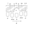
- FIG. 6 is an explanatory diagram for explaining one-side fuel injection grooves in one embodiment of the present disclosure.
- the above-described one-side fuel injection groove 8 is a groove of an upstream wall 81 positioned upstream in the flow direction of the swirl flow SF formed inside the cylinder 2.
- the height H1 is higher than the groove height H2 of the downstream wall 82 positioned downstream in the flow direction of the swirl flow SF.
- the upstream side in the flow direction of the swirl flow SF may simply be referred to as the upstream side
- the downstream side in the flow direction of the swirl flow SF may simply be referred to as the downstream side.
- Groove heights H1 and H2 refer to heights from the deepest portion 83 of the one-side fuel injection groove 8 .
- FIG. 7 is an explanatory diagram for explaining one-side fuel injection grooves according to a comparative example.
- FC1 in FIGS. 6 and 7 indicates the center of the fuel injected from the one-side fuel injection device 5A.
- the groove height of the upstream wall 081 and the groove height of the downstream wall 082 are the same.
- the swirl flow SF may interfere with the fuel passing through the one-side fuel injection groove 08 .
- the fuel passing through the one-side fuel injection groove 08 may be flowed downstream by the swirl flow SF and adhere to the wall surface (downstream wall 082) of the one-side piston 3.
- the swirl flow SF is It is possible to divert the flow so as not to enter the fuel injection groove 8 .
- the swirl flow SF By deflecting the swirl flow SF, it is possible to suppress the interference of the swirl flow SF with the fuel passing through the one-side fuel injection groove 8, so that the fuel passing through the one-side fuel injection groove 8 is flowed by the swirl flow SF.
- adhesion to the wall surface of the one-side piston 3 can be suppressed.
- fuel can be supplied to the combustion space 11 ⁇ /b>A without adhering to the wall surface of the one-side piston 3 , so an increase in unburned loss in the opposed-piston engine 1 can be suppressed.
- the one-side outer peripheral edge portion 32 (top surface 31) described above includes a first one-side outer peripheral edge portion 32A extending upstream from the upstream wall 81, and a first one-side outer peripheral edge portion 32A extending from the downstream wall 82 to the downstream side. and a second one-side outer peripheral edge portion 32B extending to the .
- the first one-side outer peripheral edge portion 32A may be inclined so that the height decreases toward the upstream side.
- the second one-side outer peripheral edge portion 32B may be inclined so that its height increases toward the downstream side.
- the swirl flow SF can be deflected by the inclined first one-side outer peripheral edge portion 32A and the inclined second one-side outer peripheral edge portion 32B. Interference of the swirl flow SF with the fuel can be effectively suppressed.
- the top surface 41 of the other side piston 4 is formed with the other side groove portion 46 which is recessed at a position facing the one side fuel injection groove 8 in the cylinder 2. good.
- the groove height H3 of the upstream wall 47 of the other side groove portion 46 is lower than the groove height H4 of the downstream wall 48 thereof.
- the groove heights H3 and H4 mean heights from the deepest portion 49 of the groove portion 46 on the other side. In this case, the swirl flow can be guided so as to bypass the one-side fuel injection groove 8 by the other-side groove portion 46, so that the interference of the swirl flow SF with the fuel passing through the one-side fuel injection groove 8 can be effectively prevented. can be suppressed to
- FIG. 8 is an explanatory diagram for explaining the other side fuel injection groove in one embodiment of the present disclosure.
- FC2 in FIG. 8 indicates the center of the fuel injected from the other side fuel injection device 5B.
- the other side fuel injection groove 9 described above has a groove height H5 of the upstream wall 91 located upstream in the direction of flow of the swirl flow SF. is higher than the groove height H6 of the downstream wall 92 located on the downstream side in the flow direction.
- Groove heights H5 and H6 mean heights from the deepest portion 93 of the other side fuel injection groove 9 .
- the swirl flow SF is reduced.
- the flow can be diverted so as not to enter the other side fuel injection groove 9 .
- deflecting the swirl flow SF it is possible to suppress the interference of the swirl flow SF with the fuel passing through the other side fuel injection groove 9, so that the fuel passing through the other side fuel injection groove 9 is flowed by the swirl flow SF.
- adhesion to the wall surface of the other side piston 4 can be suppressed.
- fuel can be supplied to the combustion space 11 ⁇ /b>A without adhering to the wall surface of the other-side piston 4 , so an increase in unburned loss in the opposed-piston engine 1 can be suppressed.
- the other side outer peripheral edge portion 42 (top surface 41) described above includes a first other side outer peripheral edge portion 42A extending upstream from the upstream wall 91, and a first other side outer peripheral edge portion 42A extending from the downstream wall 92 to the downstream side. and a second other-side outer peripheral edge portion 42B extending to.
- the first other-side outer peripheral edge portion 42A may be inclined so that the height decreases toward the upstream side.
- the second other-side outer peripheral edge portion 42B may be inclined so that its height increases toward the downstream side.
- the swirl flow SF can be deflected by the inclined first other-side outer peripheral edge portion 42A and the inclined second other-side outer peripheral edge portion 42B, so that the swirl flow SF passes through the other-side fuel injection groove 9. Interference of the swirl flow SF with the fuel can be effectively suppressed.
- the top surface 31 of the one-side piston 3 is formed with a one-side groove portion 36 that is recessed at a position facing the other-side fuel injection groove 9 in the cylinder 2. good.
- the groove height H7 of the upstream wall 37 of the one side groove portion 36 is lower than the groove height H8 of the downstream wall 38 thereof.
- Groove heights H7 and H8 mean heights from the deepest portion 39 of the one side groove portion 36 .
- the one-side groove portion 36 can guide the swirl flow so as to bypass the other-side fuel injection groove 9, so that the interference of the swirl flow SF with the fuel passing through the other-side fuel injection groove 9 can be effectively prevented. can be suppressed to
- the one side fuel injection groove 8 described above is aligned with the axis 25 of the cylinder 2 (the axis of the inner surface 22 of the cylinder 2) with respect to the other side fuel injection groove 9 described above. They are displaced in the circumferential direction so as to face each other across the center of the cross section in the direction orthogonal to the direction. In one embodiment, the one-side fuel injection groove 8 is displaced from the other-side fuel injection groove 9 in the circumferential direction of the cylinder 2 within 180° ⁇ 5°.
- the one-side fuel injection groove 8 is circumferentially displaced so as to face the other-side fuel injection groove 9 with the axis 25 of the cylinder 2 interposed therebetween.
- the swirl flow SF drifted in the other side fuel injection groove 9 can be suppressed from entering the one side fuel injection groove 8, and the swirl flow SF drifted in the one side fuel injection groove 8 can be prevented from flowing into the other side fuel injection groove. 9 can be suppressed.
- the fuel can be supplied to the combustion space 11A without adhering to the wall surfaces of the one-side piston 3 and the other-side piston 4, so an increase in unburned loss in the opposed-piston engine 1 can be suppressed.
- the central axis CA1 of the one-side fuel injection device 5A described above extends from the outside to the inside in the radial direction of the cylinder 2 toward the one side in the axial direction (one side). side where the piston 3 is located).
- the central axis CA2 of the other side fuel injection device 5B described above is inclined toward the other side (the side where the other side piston 4 is located) in the axial direction as it goes from the outside to the inside in the radial direction of the cylinder 2 .
- the one-side fuel injection device 5A injects fuel into the cylinder bore 21 along the extension direction of the central axis CA1.
- the other side fuel injection device 5B injects fuel into the cylinder bore 21 along the extension direction of the central axis CA2.
- the injection direction directed by the injection hole 51A of the one-side fuel injection device 5A may be inclined at an acute angle by a predetermined angle with respect to the extending direction of the central axis CA1.
- the injection direction directed by the injection hole 51B of the other side fuel injection device 5B may be inclined at an acute angle by a predetermined angle with respect to the extending direction of the center axis CA2.
- the fuel injected from the one-side fuel injection device 5A is directed along the extending direction of the central axis CA1 of the one-side fuel injection device 5A, i.e., the one-side fuel injection It flows towards the bottom side of the groove 8. Therefore, in the one-side fuel injection groove 8, it is possible to effectively suppress the interference between the fuel injected from the one-side fuel injection device 5A and the swirl flow SF.
- the fuel injected from the other side fuel injection device 5B is directed to the other side of the axial direction, that is, the bottom side of the other side fuel injection groove 9 along the extension direction of the central axis CA2 of the other side fuel injection device 5B.
- the other side fuel injection groove 9 it is possible to effectively suppress interference between the fuel injected from the other side fuel injection device 5B and the swirl flow SF.
- the fuel can be supplied to the combustion space 11A without adhering to the wall surfaces of the one-side piston 3 and the other-side piston 4, so an increase in unburned loss in the opposed-piston engine 1 can be suppressed.
- FIG. 9 is an explanatory diagram for explaining a scavenging port in one embodiment of the present disclosure.
- FIG. 9 shows the one-side piston 3 at the bottom dead center.
- the one-side fuel injection groove 8 described above has a groove height H1 of the upstream wall 81 that is higher than a groove height H2 of the downstream wall 82 .
- the inner surface 22 of the cylinder 2 described above includes a first scavenging port 23A formed upstream of the one-side fuel injection groove 8 in the flow direction of the swirl flow SF, and a one-side fuel injection port 23A.
- a second scavenging port 23B is formed downstream of the groove 8 in the flow direction of the swirl flow SF.
- the first scavenging port 23A is located on the other side in the axial direction (the side where the other side piston 4 is located) relative to the second scavenging port 23B.
- the first scavenging port 23A is the scavenging port 23 formed closest to the one-side fuel injection groove 8 among the scavenging ports 23 formed upstream of the one-side fuel injection groove 8 .
- the second scavenging port 23B is the scavenging port 23 formed closest to the one-side fuel injection groove 8 among the scavenging ports 23 formed downstream of the one-side fuel injection groove 8 .
- Each of the plurality of scavenging ports 23 is formed at a position shifted from at least one of the other scavenging ports 23 in the axial direction of the cylinder 2 so as not to overlap the one-side piston 3 at the bottom dead center.
- the groove height H1 of the upstream wall 81 is higher than the groove height H2 of the downstream wall 82 .
- the first scavenging port 23A formed upstream of the one-side fuel injection groove 8 is formed on the other axial side of the second scavenging port 23B formed downstream of the one-side fuel injection groove 8.
- FIG. 10 is an explanatory diagram for explaining the exhaust port in one embodiment of the present disclosure.
- FIG. 10 shows the one-side piston 3 at the bottom dead center.
- the one-side fuel injection groove 8 described above has a groove height H1 of the upstream wall 81 that is higher than a groove height H2 of the downstream wall 82 .
- the inner surface 22 of the cylinder 2 includes a first exhaust port 24A formed upstream of the one-side fuel injection groove 8 in the flow direction of the swirl flow SF, and a one-side fuel injection port 24A. and a second exhaust port 24B formed downstream of the groove 8 in the flow direction of the swirl flow SF.
- the first exhaust port 24A is located on the other side in the axial direction (the side where the other side piston 4 is located) relative to the second exhaust port 24B.
- the first exhaust port 24A is the exhaust port 24 formed closest to the one-side fuel injection groove 8 among the exhaust ports 24 formed upstream of the one-side fuel injection groove 8 .
- the second exhaust port 24B is the exhaust port 24 formed closest to the one-side fuel injection groove 8 among the exhaust ports 24 formed downstream of the one-side fuel injection groove 8 .
- Each of the plurality of exhaust ports 24 is formed at a position offset from at least one of the other exhaust ports 24 in the axial direction of the cylinder 2 so as not to overlap the one-side piston 3 at the bottom dead center.
- the groove height H1 of the upstream wall 81 is higher than the groove height H2 of the downstream wall 82 .
- the first exhaust port 24A formed upstream of the one-side fuel injection groove 8 is formed on the other axial side of the second exhaust port 24B formed downstream of the one-side fuel injection groove 8.
- An opposed-piston engine (1) according to at least one embodiment of the present disclosure, a cylinder (2); a one-side piston (3) arranged on one side in the axial direction inside the cylinder (2); a second side piston (4) disposed on the other side in the axial direction inside the cylinder (2), A one-side cavity (6) recessed toward the center is formed on the top surface (31) of the one-side piston (3), The top surface (41) of the other side piston (4) is formed with the other side cavity (7) recessed toward the center, When the diameter of the top surface (31) of the one-side piston (3) is D1, the outer peripheral edge (61) of the one-side cavity (6) is the top surface (31) of the one-side piston (3).
- the outer peripheral edge (61) of the one-side cavity (6) extends over the entire circumference from the outer peripheral edge (34) of the top surface (31) of the one-side piston (3) by a predetermined distance or more.
- the outer peripheral edge (71) of the cavity (7) on the other side is separated from the outer peripheral edge (44) of the top surface (41) of the piston (4) on the other side by a predetermined distance or more over the entire circumference. is provided. Therefore, the one-side cavity (6) and the other-side cavity (7) form a combustion space (11A) in the center of the combustion chamber (11). Combustion can be completed in the combustion space (11A) by compressing the combustion gas in the combustion space (11A) and injecting the fuel into the combustion space (11A).
- the combustion flame can be suppressed from reaching the outer peripheral portions (33, 43) of the one-side piston (3) and the other-side piston (4), so that the one-side piston (3) and the other-side piston (4) It is possible to reduce the heat load on the outer peripheral portions (33, 43).
- the opposed-piston engine (1) of 1) above The one-side piston (3) extends from the outer peripheral edge (61) of the one-side cavity (6) to the outer peripheral edge (34) of the top surface (31) of the one-side piston (3).
- one side fuel injection groove (8) present is formed,
- the one-side fuel injection groove (8) has a groove height (H1) on the upstream side (upstream wall 81) in the flow direction of the swirl flow (SF) formed inside the cylinder (2).
- (SF) is higher than the groove height (H2) on the downstream side (downstream wall 82) in the flow direction.
- the groove height (H1) on the upstream side (upstream wall 81) of the one-side fuel injection groove (8) is higher than the groove height (H2) on the downstream side (downstream wall 82).
- the swirl flow (SF) can be deflected so as not to enter the one-side fuel injection groove (8).
- the swirl flow (SF) By deflecting the swirl flow (SF), it is possible to suppress the interference of the swirl flow (SF) with the fuel passing through the one-side fuel injection groove (8), so the fuel passing through the one-side fuel injection groove (8) is swirled by the swirl flow (SF) and is prevented from adhering to the wall surface of the one-side piston (3).
- the fuel can be supplied to the combustion space (11A) without adhering to the wall surface of the one-side piston (3), thereby suppressing an increase in unburned loss in the opposed-piston engine (1).
- the other piston (4) extends from the outer peripheral edge (71) of the other cavity (7) to the outer peripheral edge (44) of the top surface (41) of the other piston (4).
- the existing other side fuel injection groove (9) is formed, In the other side fuel injection groove (9), the groove height (H5) on the upstream side (upstream wall 91) in the flow direction of the swirl flow (SF) is adjusted to the downstream side in the flow direction of the swirl flow (SF) ( higher than the groove height (H6) of the downstream wall 92).
- the groove height (H5) on the upstream side (upstream wall 91) of the other side fuel injection groove (9) is higher than the groove height (H6) on the downstream side (downstream wall 92).
- the swirl flow (SF) can be deflected so as not to enter the other side fuel injection groove (9).
- the swirl flow (SF) By deflecting the swirl flow (SF), it is possible to suppress the interference of the swirl flow (SF) with the fuel passing through the other side fuel injection groove (9), so that the fuel passing through the other side fuel injection groove (9) is swirled by the swirl flow (SF) and is prevented from adhering to the wall surface of the other side piston (4).
- the fuel can be supplied to the combustion space (11A) without adhering to the wall surface of the other side piston (4), thereby suppressing an increase in unburned loss in the opposed-piston engine (1).
- the one-side fuel injection groove (8) is circumferentially displaced so as to face the other-side fuel injection groove (9) across the axis (25) of the cylinder (2). .
- the one side fuel injection groove (8) is arranged in the circumferential direction so as to face the other side fuel injection groove (9) across the axis (25) of the cylinder (2). They are staggered.
- the swirl flow (SF) drifted in the other side fuel injection groove (9) can be suppressed from entering the one side fuel injection groove (8), and the swirl flow drifted in the one side fuel injection groove (8) can be suppressed.
- the fuel can be supplied to the combustion space (11A) without adhering to the walls of the one-side piston (3) and the other-side piston (4). You can control the increase.
- the opposed-piston engine (1) of 4) above further comprising at least one fuel injector (5) configured to inject fuel between the one side piston (3) and the other side piston (4) inside the cylinder (2); said at least one fuel injector (5) comprising: a one-side fuel injection device (5A) arranged so that the injected fuel passes through the one-side fuel injection groove (8); and a second side fuel injection device (5B) arranged so that the injected fuel passes through the second side fuel injection groove (9).
- the fuel injected by the one-side fuel injection device (5A) passes through the one-side fuel injection groove (8) and is supplied to the combustion space (11A). Further, the fuel injected by the other side fuel injection device (5B) passes through the other side fuel injection groove (9) and is supplied to the combustion space (11A). In this way, the fuel supplied to the combustion space (11A) passes through the one-side fuel injection groove (8) and the other-side fuel injection groove (9), thereby suppressing the interference of the swirl flow (SF).
- SF swirl flow
- a central axis (CA1) of the one-side fuel injection device (5A) is inclined toward the one side in the axial direction as it goes from the outer side to the inner side in the radial direction of the cylinder (2)
- the center axis (CA2) of the other side fuel injection device (5B) is inclined toward the other side in the axial direction as it goes from the outside to the inside in the radial direction of the cylinder (2).
- the fuel injected from the one-side fuel injection device (5A) is directed along the extending direction of the central axis (CA1) of the one-side fuel injection device (5A). side, i.e., toward the bottom side of the one-side fuel injection groove (8). Therefore, it is possible to effectively suppress interference between the fuel injected from the one-side fuel injection device (5A) and the swirl flow (SF) in the one-side fuel injection groove (8).
- the fuel injected from the other side fuel injection device (5B) is directed along the extending direction of the central axis (CA2) of the other side fuel injection device (5B) to the other side of the axial direction, i.e., the other side fuel It flows towards the bottom side of the injection groove (9).
- an opposed-piston engine (1) according to any of 2) to 6) above, wherein A first scavenging port (23A) formed on the inner surface (22) of the cylinder (2) upstream of the one-side fuel injection groove (8) in the flow direction of the swirl flow (SF); a second scavenging port (23B) formed downstream of the one-side fuel injection groove (8) in the flow direction of the swirl flow (SF), The first scavenging port (23A) is located on the other side in the axial direction relative to the second scavenging port (23B).
- the one-side fuel injection groove (8) has a groove height (H1) on the upstream side (upstream wall 81) that is higher than a groove height (H2) on the downstream side (downstream wall 82). high.
- the first scavenging port (23A) formed on the upstream side of the one-side fuel injection groove (8) is positioned further than the second scavenging port (23B) formed on the downstream side of the one-side fuel injection groove (8).
- an opposed-piston engine (1) according to any of 2) to 6) above, A first exhaust port (24A) formed on the inner surface (22) of the cylinder (2) upstream of the one-side fuel injection groove (8) in the flow direction of the swirl flow (SF); a second exhaust port (24B) formed downstream of the one-side fuel injection groove (8) in the flow direction of the swirl flow, The first exhaust port (24A) is located on the other side in the axial direction relative to the second exhaust port (24B).
- the one-side fuel injection groove (8) has a groove height (H1) on the upstream side (upstream wall 81) that is higher than a groove height (H2) on the downstream side (downstream wall 82). high.
- the first exhaust port (24A) formed on the upstream side of the one-side fuel injection groove (8) is positioned further than the second exhaust port (24B) formed on the downstream side of the one-side fuel injection groove (8).
- an opposed-piston engine (1) according to any one of 1) through 8) above, wherein The one side cavity (6) and the other side cavity (7) are hemispherical.
- the one side cavity (6) and the other side cavity (7) are made hemispherical so that the volume of the spherical combustion space (11A) formed at the center of the combustion chamber (11) is while ensuring the outer peripheral edges (61, 71) of the one-side cavity (6) and the other-side cavity (7), the outer peripheral edges (34, 44) can be made large.
- the heat load on the outer peripheral portions (33, 43) of the one-side piston (3) and the other-side piston (4) can be effectively reduced.
Landscapes
- Engineering & Computer Science (AREA)
- Chemical & Material Sciences (AREA)
- Combustion & Propulsion (AREA)
- Mechanical Engineering (AREA)
- General Engineering & Computer Science (AREA)
- Combustion Methods Of Internal-Combustion Engines (AREA)
- Cylinder Crankcases Of Internal Combustion Engines (AREA)
Priority Applications (1)
| Application Number | Priority Date | Filing Date | Title |
|---|---|---|---|
| US18/278,754 US12104525B2 (en) | 2021-03-26 | 2022-03-22 | Opposed-piston engine |
Applications Claiming Priority (2)
| Application Number | Priority Date | Filing Date | Title |
|---|---|---|---|
| JP2021053560A JP7586749B2 (ja) | 2021-03-26 | 2021-03-26 | 対向ピストンエンジン |
| JP2021-053560 | 2021-03-26 |
Publications (1)
| Publication Number | Publication Date |
|---|---|
| WO2022202746A1 true WO2022202746A1 (ja) | 2022-09-29 |
Family
ID=83397418
Family Applications (1)
| Application Number | Title | Priority Date | Filing Date |
|---|---|---|---|
| PCT/JP2022/012971 Ceased WO2022202746A1 (ja) | 2021-03-26 | 2022-03-22 | 対向ピストンエンジン |
Country Status (3)
| Country | Link |
|---|---|
| US (1) | US12104525B2 (enExample) |
| JP (1) | JP7586749B2 (enExample) |
| WO (1) | WO2022202746A1 (enExample) |
Families Citing this family (1)
| Publication number | Priority date | Publication date | Assignee | Title |
|---|---|---|---|---|
| JP2026075975A (ja) * | 2024-10-23 | 2026-05-11 | 三菱重工業株式会社 | 内燃機関 |
Citations (2)
| Publication number | Priority date | Publication date | Assignee | Title |
|---|---|---|---|---|
| JPH02215957A (ja) * | 1989-02-16 | 1990-08-28 | Suzuki Motor Co Ltd | 2サイクルエンジンのピストン |
| US20130036999A1 (en) * | 2011-08-08 | 2013-02-14 | Ecomotors International, Inc. | High-Squish Combustion Chamber With Side Injection |
Family Cites Families (9)
| Publication number | Priority date | Publication date | Assignee | Title |
|---|---|---|---|---|
| JP2007107475A (ja) | 2005-10-14 | 2007-04-26 | Denso Corp | 2サイクルエンジン |
| WO2011139332A2 (en) | 2010-04-27 | 2011-11-10 | Achates Power, Inc. | Combustion chamber constructions for opposed-piston engines |
| US8820294B2 (en) | 2010-08-16 | 2014-09-02 | Achates Power, Inc. | Fuel injection spray patterns for opposed-piston engines |
| DE102012011159A1 (de) * | 2012-06-05 | 2013-12-05 | Günter Elsbett | Brennraum für Gegenkolbenmotoren |
| CN104662281A (zh) | 2012-09-25 | 2015-05-27 | 阿凯提兹动力公司 | 对置活塞式发动机中具有涡流喷雾模式的燃料喷射 |
| JP5575284B2 (ja) | 2013-02-04 | 2014-08-20 | 三菱重工業株式会社 | エンジン排気エネルギー回収方法 |
| CN106715866B (zh) * | 2014-09-29 | 2019-06-21 | 沃尔沃卡车集团 | 包括其中具有锥形凹部的活塞的活塞对置式发动机 |
| US9995213B2 (en) * | 2015-03-31 | 2018-06-12 | Achates Power, Inc. | Asymmetrically-shaped combustion chamber for opposed-piston engines |
| JP7321108B2 (ja) | 2020-01-30 | 2023-08-04 | 三菱重工業株式会社 | 2サイクル対向ピストンエンジン |
-
2021
- 2021-03-26 JP JP2021053560A patent/JP7586749B2/ja active Active
-
2022
- 2022-03-22 WO PCT/JP2022/012971 patent/WO2022202746A1/ja not_active Ceased
- 2022-03-22 US US18/278,754 patent/US12104525B2/en active Active
Patent Citations (2)
| Publication number | Priority date | Publication date | Assignee | Title |
|---|---|---|---|---|
| JPH02215957A (ja) * | 1989-02-16 | 1990-08-28 | Suzuki Motor Co Ltd | 2サイクルエンジンのピストン |
| US20130036999A1 (en) * | 2011-08-08 | 2013-02-14 | Ecomotors International, Inc. | High-Squish Combustion Chamber With Side Injection |
Also Published As
| Publication number | Publication date |
|---|---|
| US12104525B2 (en) | 2024-10-01 |
| US20230392544A1 (en) | 2023-12-07 |
| JP2022150793A (ja) | 2022-10-07 |
| JP7586749B2 (ja) | 2024-11-19 |
Similar Documents
| Publication | Publication Date | Title |
|---|---|---|
| CN103097686B (zh) | 对置活塞式发动机的活塞构造 | |
| US20090020958A1 (en) | Methods and apparatus for operating an internal combustion engine | |
| JP5497796B2 (ja) | 内燃エンジン | |
| AU2016294564B2 (en) | Free piston engine | |
| US12320312B2 (en) | Piston assembly with opposing injection regions for an opposed-piston engine | |
| CN105221286A (zh) | 发动机汽缸冷却腔 | |
| WO2016160342A1 (en) | Asymmetrically-shaped combustion chamber for opposed-piston engines | |
| KR20180122674A (ko) | 내연 기관 | |
| EP2948664B1 (en) | Piston crown bowls defining combustion chamber constructions in opposed-piston engines | |
| JP2022150793A (ja) | 対向ピストンエンジン | |
| US11795867B2 (en) | Opposed-piston engine | |
| EP3511556B1 (en) | Piston for internal combustion engine | |
| US20160252065A1 (en) | Opposed Piston Three Nozzle Combustion Chamber Design | |
| JP7638080B2 (ja) | シリンダライナおよび舶用内燃機関 | |
| JP7708568B2 (ja) | 対向ピストンエンジン | |
| JP2025110666A (ja) | 対向ピストンエンジン | |
| WO2026088604A1 (ja) | 内燃機関 | |
| US20080271597A1 (en) | Methods and apparatus for operating an internal combustion engine | |
| US20260043374A1 (en) | Internal combustion engine | |
| JPH0151898B2 (enExample) |
Legal Events
| Date | Code | Title | Description |
|---|---|---|---|
| 121 | Ep: the epo has been informed by wipo that ep was designated in this application |
Ref document number: 22775530 Country of ref document: EP Kind code of ref document: A1 |
|
| NENP | Non-entry into the national phase |
Ref country code: DE |
|
| 122 | Ep: pct application non-entry in european phase |
Ref document number: 22775530 Country of ref document: EP Kind code of ref document: A1 |