WO2022202702A1 - Plasma processing apparatus and filter unit - Google Patents
Plasma processing apparatus and filter unit Download PDFInfo
- Publication number
- WO2022202702A1 WO2022202702A1 PCT/JP2022/012789 JP2022012789W WO2022202702A1 WO 2022202702 A1 WO2022202702 A1 WO 2022202702A1 JP 2022012789 W JP2022012789 W JP 2022012789W WO 2022202702 A1 WO2022202702 A1 WO 2022202702A1
- Authority
- WO
- WIPO (PCT)
- Prior art keywords
- filter
- coil
- toroidal
- core
- plasma processing
- Prior art date
Links
- 238000012545 processing Methods 0.000 title claims abstract description 83
- 229910000859 α-Fe Inorganic materials 0.000 claims abstract description 16
- 239000000696 magnetic material Substances 0.000 claims abstract description 13
- 239000003990 capacitor Substances 0.000 claims description 21
- 230000035699 permeability Effects 0.000 claims description 14
- 239000000463 material Substances 0.000 claims description 6
- 239000002159 nanocrystal Substances 0.000 abstract 1
- 238000010438 heat treatment Methods 0.000 description 39
- 235000012431 wafers Nutrition 0.000 description 37
- 239000004020 conductor Substances 0.000 description 31
- 239000000758 substrate Substances 0.000 description 19
- 230000000694 effects Effects 0.000 description 17
- 230000006870 function Effects 0.000 description 14
- RYGMFSIKBFXOCR-UHFFFAOYSA-N Copper Chemical compound [Cu] RYGMFSIKBFXOCR-UHFFFAOYSA-N 0.000 description 13
- 230000020169 heat generation Effects 0.000 description 11
- 230000009471 action Effects 0.000 description 9
- XEEYBQQBJWHFJM-UHFFFAOYSA-N Iron Chemical group [Fe] XEEYBQQBJWHFJM-UHFFFAOYSA-N 0.000 description 8
- 229910018605 Ni—Zn Inorganic materials 0.000 description 8
- 238000005530 etching Methods 0.000 description 8
- 238000009826 distribution Methods 0.000 description 6
- 238000000034 method Methods 0.000 description 6
- 229910052782 aluminium Inorganic materials 0.000 description 5
- XAGFODPZIPBFFR-UHFFFAOYSA-N aluminium Chemical compound [Al] XAGFODPZIPBFFR-UHFFFAOYSA-N 0.000 description 5
- 239000002826 coolant Substances 0.000 description 5
- 238000010586 diagram Methods 0.000 description 5
- 230000001629 suppression Effects 0.000 description 5
- 230000000903 blocking effect Effects 0.000 description 4
- 239000011889 copper foil Substances 0.000 description 4
- 238000013461 design Methods 0.000 description 4
- 238000005516 engineering process Methods 0.000 description 4
- 238000002474 experimental method Methods 0.000 description 4
- 229910052742 iron Inorganic materials 0.000 description 4
- 239000004065 semiconductor Substances 0.000 description 4
- 238000012546 transfer Methods 0.000 description 4
- 230000008859 change Effects 0.000 description 3
- 229910052802 copper Inorganic materials 0.000 description 3
- 239000010949 copper Substances 0.000 description 3
- 150000002500 ions Chemical class 0.000 description 3
- 238000004519 manufacturing process Methods 0.000 description 3
- 229910052751 metal Inorganic materials 0.000 description 3
- 239000002184 metal Substances 0.000 description 3
- 230000008569 process Effects 0.000 description 3
- 238000003860 storage Methods 0.000 description 3
- 238000004804 winding Methods 0.000 description 3
- 230000015556 catabolic process Effects 0.000 description 2
- 230000000052 comparative effect Effects 0.000 description 2
- 230000007423 decrease Effects 0.000 description 2
- 238000001914 filtration Methods 0.000 description 2
- 239000011810 insulating material Substances 0.000 description 2
- 238000009413 insulation Methods 0.000 description 2
- 239000012212 insulator Substances 0.000 description 2
- 239000000203 mixture Substances 0.000 description 2
- 239000004593 Epoxy Substances 0.000 description 1
- 239000000498 cooling water Substances 0.000 description 1
- 239000013078 crystal Substances 0.000 description 1
- 230000006866 deterioration Effects 0.000 description 1
- 239000003989 dielectric material Substances 0.000 description 1
- 230000005684 electric field Effects 0.000 description 1
- 239000011521 glass Substances 0.000 description 1
- 230000001771 impaired effect Effects 0.000 description 1
- 230000006872 improvement Effects 0.000 description 1
- 230000007257 malfunction Effects 0.000 description 1
- 230000007246 mechanism Effects 0.000 description 1
- 230000003647 oxidation Effects 0.000 description 1
- 238000007254 oxidation reaction Methods 0.000 description 1
- 238000005268 plasma chemical vapour deposition Methods 0.000 description 1
- 238000009832 plasma treatment Methods 0.000 description 1
- 230000001902 propagating effect Effects 0.000 description 1
- 230000005855 radiation Effects 0.000 description 1
- 239000011347 resin Substances 0.000 description 1
- 229920005989 resin Polymers 0.000 description 1
- 238000004544 sputter deposition Methods 0.000 description 1
Images


Classifications
-
- H—ELECTRICITY
- H01—ELECTRIC ELEMENTS
- H01F—MAGNETS; INDUCTANCES; TRANSFORMERS; SELECTION OF MATERIALS FOR THEIR MAGNETIC PROPERTIES
- H01F17/00—Fixed inductances of the signal type
- H01F17/04—Fixed inductances of the signal type with magnetic core
- H01F17/06—Fixed inductances of the signal type with magnetic core with core substantially closed in itself, e.g. toroid
-
- H—ELECTRICITY
- H01—ELECTRIC ELEMENTS
- H01L—SEMICONDUCTOR DEVICES NOT COVERED BY CLASS H10
- H01L21/00—Processes or apparatus adapted for the manufacture or treatment of semiconductor or solid state devices or of parts thereof
- H01L21/02—Manufacture or treatment of semiconductor devices or of parts thereof
- H01L21/04—Manufacture or treatment of semiconductor devices or of parts thereof the devices having at least one potential-jump barrier or surface barrier, e.g. PN junction, depletion layer or carrier concentration layer
- H01L21/18—Manufacture or treatment of semiconductor devices or of parts thereof the devices having at least one potential-jump barrier or surface barrier, e.g. PN junction, depletion layer or carrier concentration layer the devices having semiconductor bodies comprising elements of Group IV of the Periodic System or AIIIBV compounds with or without impurities, e.g. doping materials
- H01L21/30—Treatment of semiconductor bodies using processes or apparatus not provided for in groups H01L21/20 - H01L21/26
- H01L21/302—Treatment of semiconductor bodies using processes or apparatus not provided for in groups H01L21/20 - H01L21/26 to change their surface-physical characteristics or shape, e.g. etching, polishing, cutting
- H01L21/306—Chemical or electrical treatment, e.g. electrolytic etching
- H01L21/3065—Plasma etching; Reactive-ion etching
-
- H—ELECTRICITY
- H01—ELECTRIC ELEMENTS
- H01L—SEMICONDUCTOR DEVICES NOT COVERED BY CLASS H10
- H01L21/00—Processes or apparatus adapted for the manufacture or treatment of semiconductor or solid state devices or of parts thereof
- H01L21/02—Manufacture or treatment of semiconductor devices or of parts thereof
- H01L21/04—Manufacture or treatment of semiconductor devices or of parts thereof the devices having at least one potential-jump barrier or surface barrier, e.g. PN junction, depletion layer or carrier concentration layer
- H01L21/18—Manufacture or treatment of semiconductor devices or of parts thereof the devices having at least one potential-jump barrier or surface barrier, e.g. PN junction, depletion layer or carrier concentration layer the devices having semiconductor bodies comprising elements of Group IV of the Periodic System or AIIIBV compounds with or without impurities, e.g. doping materials
- H01L21/30—Treatment of semiconductor bodies using processes or apparatus not provided for in groups H01L21/20 - H01L21/26
- H01L21/31—Treatment of semiconductor bodies using processes or apparatus not provided for in groups H01L21/20 - H01L21/26 to form insulating layers thereon, e.g. for masking or by using photolithographic techniques; After treatment of these layers; Selection of materials for these layers
-
- H—ELECTRICITY
- H03—ELECTRONIC CIRCUITRY
- H03H—IMPEDANCE NETWORKS, e.g. RESONANT CIRCUITS; RESONATORS
- H03H7/00—Multiple-port networks comprising only passive electrical elements as network components
- H03H7/01—Frequency selective two-port networks
-
- H—ELECTRICITY
- H03—ELECTRONIC CIRCUITRY
- H03H—IMPEDANCE NETWORKS, e.g. RESONANT CIRCUITS; RESONATORS
- H03H7/00—Multiple-port networks comprising only passive electrical elements as network components
- H03H7/01—Frequency selective two-port networks
- H03H7/075—Ladder networks, e.g. electric wave filters
-
- H—ELECTRICITY
- H05—ELECTRIC TECHNIQUES NOT OTHERWISE PROVIDED FOR
- H05H—PLASMA TECHNIQUE; PRODUCTION OF ACCELERATED ELECTRICALLY-CHARGED PARTICLES OR OF NEUTRONS; PRODUCTION OR ACCELERATION OF NEUTRAL MOLECULAR OR ATOMIC BEAMS
- H05H1/00—Generating plasma; Handling plasma
- H05H1/24—Generating plasma
- H05H1/46—Generating plasma using applied electromagnetic fields, e.g. high frequency or microwave energy
Definitions
- the second high-frequency power supply 31 generates second high-frequency power (high-frequency bias power) LF mainly for drawing ions into the wafer W, and supplies the second high-frequency power LF to the lower electrode 12 .
- the frequency of the second high frequency power LF may be lower than the frequency of the first high frequency power HF and within the range of 400 kHz to 13.56 MHz.
- a DC (Direct Current) pulse generator may be used instead of the second high-frequency power supply 31 . In this case, the pulse frequency may be a frequency within the range of 400 kHz to 13.56 MHz.
- the electrostatic chuck 13 is a member configured to be able to attract and hold the wafer W by Coulomb force.
- the edge ring 14 is an annular member arranged so as to surround the wafer W placed on the upper surface of the central portion of the electrostatic chuck 13 .
- the edge ring 14 is provided to improve the uniformity of plasma processing (etching). For this reason, the edge ring 14 is made of a material appropriately selected according to etching, and can be made of Si or SiC, for example.
- An annular exhaust path 80 is formed between the inner wall of the chamber 10 and the support member 16 at the bottom of the chamber 10 .
- An exhaust port 81 is provided on the bottom surface of the exhaust path 80 , and the processing space S communicates with the exhaust port 81 via the exhaust path 80 .
- An exhaust device 83 is connected to the exhaust port 81 via an exhaust pipe 82 .
- the exhaust device 83 has, for example, a vacuum pump such as a turbomolecular pump, and can depressurize the processing space S to a desired degree of vacuum.
- part of the first high-frequency power HF and part of the second high-frequency power LF applied to the lower electrode 12 are applied to the inner heating wire 50a and the outer heating wire 50b inside the lower electrode 12.
- a high-frequency noise it enters into the power supply conductors 51a and 51b via. If either of these two frequencies of high frequency noise reaches the heater power supplies 54a, 54b, the operation or performance of the heater power supplies 54a, 54b may be impaired.
- the noise of the first high frequency power HF is called “first high frequency noise”
- the noise of the second high frequency power LF is called "second high frequency noise”.
- FIG. 2 is an explanatory diagram showing the circuit configuration of the filter unit 52a.
- FIG. 3 is a longitudinal sectional view showing the physical structure of the filter unit 52a.
- the housing 100 has a substantially L shape when viewed from the side. That is, the housing 100 has a vertically extending portion 100a extending in the vertical direction (vertical direction) and a horizontally extending portion 100b extending horizontally from the lower end of the vertically extending portion 100a.
- the housing 100 is electrically conductive as described above, is made of aluminum, for example, and is grounded.
- the vertical axis of the air-core coils 110a and 110b, the vertical axis of the toroidal coil 120a, and the vertical axis of the toroidal coil 120b are different. Since the vertical axes are different in this way, the effect of the electric field during plasma processing is greater than when the vertical axes of the air-core coils 110a and 110b and the vertical axes of the toroidal coils 120a and 120b are coaxial, for example. can be made difficult.
- the front stage and the rear stage viewed from the inner heating wire 50a may be simply referred to as the "front stage" and the "back stage", respectively.
- connection cable 130 is provided over the vertically extending portion 100a and the horizontally extending portion 100b.
- the connection cable 130 has an upper end fixed to a substrate 144 described later, and a lower end fixed to a substrate 160 described later.
- the length of the connection cable 130 of the filter unit 52a and the length of the connection cable 130 of the filter unit 52b are the same.
- the air-core coils 110a and 110b are edgewise wound coils.
- the coil conductors of the air-core coils 110a and 110b are overlapped in the axial direction (vertical direction) and translated in the air-core coils 110a and 110b.
- the winding pitch can be arbitrarily designed, it is designed to ensure the characteristics of a high-frequency filter, as disclosed in Japanese Unexamined Patent Application Publication No. 2015-173027, for example.
- the air-core coils 110a and 110b are respectively supported by substantially cylindrical support members 140a and 140b.
- the support members 140a and 140b are supported on the inner surface of the vertically extending portion 100a. Concavities and convexities are formed on the inner surfaces of the support members 140a and 140b, and the winding portions of the air-core coils 110a and 110b are fixed to the concavities and convexities. Further, the support members 140a and 140b are made of resin, for example.
- the upper end terminal of the air-core coil 110b in the latter stage is fixed to the substrate 143. That is, the lower end terminal of the air core coil 110a and the upper end terminal of the air core coil 110b are fixed to the substrate 143, and the air core coils 110a and 110b are connected in series via the substrate 143.
- FIG. A lower end terminal of the air core coil 110 b is fixed to the substrate 144 .
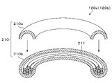
- Each of the toroidal coils 120a and 120b has a structure in which a coil conductor 151 made of, for example, copper wire is helically wound around a toroidal core 150 made of Mn—Zn ferrite.
- a coil conductor 151 made of, for example, copper wire
- a toroidal core 150 made of Mn—Zn ferrite.
- the thickness t satisfies the following formula (1).
- JP-A-2014-56706 and JP-A-2014-229565 disclose the relationship t ⁇ (ba) for a general single toroidal core.
- the following formula (1) is satisfied, that is, t is large or (ba) is small, so the magnetic permeability of the toroidal core 150 can be increased.
- the second capacitor 121 of the second filter 102 is provided on the surface of the substrate 160 .
- the second capacitor 121 is provided between the toroidal coil 120b and the terminals of the electrical cable 53a provided on the surface of the substrate 160 and between the ground.
- a fan 170 that supplies air to the inside of the housing 100 is provided on the outside of the bottom surface of the housing 100 .
- a plurality of punched holes are formed in the bottom surface of the housing 100 below the toroidal coils 120a and 120b, and a plurality of punched holes are also formed in the upper end of the vertically extending portion 100a of the housing 100.
- FIG. The air supplied from the fan 170 to the inside of the housing 100 sequentially flows through the horizontally extending portion 100b and the vertically extending portion 100a, and flows out from the upper portion of the housing 100 to the outside. At this time, the toroidal coils 120a, 120b and the air core coils 110a, 110b are cooled by air.
- the Ni--Zn toroidal core has a large noise suppression effect in the high frequency range, for example, 1 MHz to 100 MHz, and has a low magnetic permeability of, for example, 3000 H/m or less. With such a low magnetic permeability, the allowable loss (breakdown voltage) is insufficient, so if the lower electrode 12 is supplied with the second high-frequency power LF with a low frequency, the Ni—Zn toroidal core may generate heat.
- the Ni—Zn toroidal cores are connected in series or the number of stacks (the number of layers) is increased, but in such a case, the toroidal coil becomes large.
- the Mn-Zn toroidal core has a large noise suppression effect in the low frequency range, for example, 10 MHz or less, and has a high magnetic permeability of, for example, 6000 H/m or more. Therefore, even if the lower electrode 12 is supplied with the second high-frequency power LF having a low frequency, it is possible to suppress the heat generation of the Mn--Zn based toroidal core.
- the toroidal coils 120a and 120b can be miniaturized. Specifically, the toroidal coils 120a and 120b can be downsized so that the toroidal core 150 satisfies the formula (1) as described above. Furthermore, as a result of extensive studies by the present inventors, when using a Mn--Zn based toroidal core, the size of the toroidal coils 120a and 120b can be reduced to about half compared to a Ni--Zn based toroidal core. was made.
- the toroidal coils 120a and 120b can be miniaturized and the filter unit 52a can be miniaturized in this way, the degree of freedom in the layout design of the plasma processing apparatus 1, especially in the layout design of the lower part of the chamber 10 is improved. can be made As a result, even if the lower part of the chamber 10 has a limited space, a plurality of, in this embodiment, two filter units 52a and 52b can be appropriately provided.
- the thickness t of the single toroidal core is 13 mm
- the inner radius a is 19 mm
- the outer radius b is 30.5 mm.
- seven toroidal cores (7 stacks) are arranged in two in the thickness direction and four in plan view, for a total of eight.
- the thickness is 0.20 times and the planar view length is 0.29 times as large as the Ni--Zn based toroidal core.
- Coils 120a and 120b can be miniaturized.
- the toroidal coils 120a and 120b of the present embodiment when used, heat generation of the Mn--Zn toroidal core (toroidal core 150) can be suppressed and the size of the toroidal coils 120a and 120b can be reduced. Then, it becomes possible to realize a high-inductance filter for the second high-frequency noise in the low-frequency region.
- the risk of the toroidal coil heating up is due to, for example, the following causes.
- the first is copper loss heat generation, in which a coil conductor (copper wire) wound around a Ni—Zn toroidal core heats up due to current flowing from a heater power supply to a power supply line, for example.
- the second is copper loss heat generation in which the coil conductor (copper wire) heats up due to, for example, a current drawn from the plasma side to the power supply line.
- the third is iron loss heat generation, which is generated by eddy current and hysteresis loss in the Ni--Zn based toroidal core due to conductive noise propagating from the plasma side to the feed line, for example.
- the wire diameter (cross-sectional area) of the coil conductors that is allowable for the current value flowing in the power supply line should be selected.
- the iron loss of the toroidal core when using the Mn--Zn toroidal core, the iron loss is suppressed because of its high magnetic permeability in the low frequency range.
- the toroidal coils 120a and 120b of the present embodiment have a configuration in which the toroidal coils 120a and 120b are arranged in the rear stage, and the air-core coils 110a and 110b are arranged in the front stage.
- the first filter 101 (air-core coils 110a and 110b) blocks high-frequency first high-frequency noise
- the second filter 102 (toroidal coils 120a and 120b) blocks the frequency noise. blocks a second high frequency noise with a low
- the air-core coils 110a and 110b have self-resonance frequencies near the frequency of the first high-frequency power HF (first frequency)
- the toroidal coils 120a and 120b have the frequency of the second high-frequency power LF (second frequency).
- the first capacitor 111 functions to obtain a first series resonance frequency between the second frequency and the first frequency
- the second capacitor 121 functions to obtain a first series resonance frequency in a region lower than the second frequency. It functions to obtain a series resonant frequency of 2.
- the air-core coils 110a and 110b and the toroidal coils 120a and 120b share the first high-frequency noise filtering function and the second high-frequency noise filtering function, respectively, so that the filter unit 52a Overall design, manufacture, and adjustment are made easier, and machine differences are less likely to occur.
- the filter unit 52a it is preferable to replace the air core coils 110a and 110b with the toroidal coils 120a and 120b. do not have.
- the toroidal coils 120a and 120b cut off the second high-frequency noise of the first high-frequency noise and the second high-frequency noise, but cut off the second high-frequency noise of the high frequency.
- the first high frequency noise is allowed to pass. Therefore, the first high-frequency noise rushes into the toroidal coils 120a and 120b, and the high-potential first high-frequency noise is applied to the toroidal coils 120a and 120b.
- the toroidal core 150 which is a Mn—Zn toroidal core, has a low magnetic permeability in a high frequency region, the allowable loss is small. damage or burnout.
- the air-core coils 110a and 110b in the front stage block the first high-frequency noise having a high frequency
- the first high-frequency noise does not enter the toroidal coils 120a and 120b in the rear stage.
- the back electromotive force generated in the toroidal coils 120a and 120b is small, eddy currents are suppressed, and the toroidal core 150 can be prevented from generating heat to a high temperature.
- the air-core coils 110a and 110b can realize high impedance against the first high-frequency noise, and the toroidal coils 120a and 120b can realize high impedance against the second high-frequency noise. can.
- the filter unit 52a can appropriately exhibit the high-frequency noise blocking function.
- the two toroidal coils 120a and 120b are arranged in series in the second filter 102, but the arrangement of the toroidal coil 120 is not limited to this.
- FIG. 5 is an explanatory diagram schematically showing various arrangements of the toroidal coil 120.
- FIG. No. 1 is the case where one toroidal coil 120a is arranged.
- No. 2 is a case in which two toroidal coils 120a and 120b are arranged in series, which is the same arrangement as in the above embodiment (FIG. 2).
- No. 3 is a case in which two toroidal coils 120a and 120b are arranged in parallel.
- No. 4 is a case in which two serially arranged toroidal coils 120a and 120b and two serially arranged toroidal coils 120c and 120d are arranged in parallel.
- No. 1 to No. 4 toroidal coils 120a, 120b, 120c, and 120d are each the same toroidal coil.
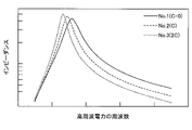
- FIG. 6 is a graph showing experimental results.
- the horizontal axis of FIG. 6 indicates the frequency of the high-frequency power, and the vertical axis indicates the impedance of the second filter 102 .
- FIG. 7 is a table summarizing the experimental results.
- No. 2 to No. 4 shows the impedance peak value, parallel resonance frequency, breakdown voltage, allowable current, permittivity/allowable loss.
- the impedance characteristics change depending on the arrangement of the toroidal coil 120. Therefore, the arrangement of these toroidal coils 120 may be appropriately selected according to the required specifications.
- FIG. FIG. 8 is a graph showing experimental results.
- the horizontal axis of FIG. 8 indicates the frequency of the high-frequency power, and the vertical axis indicates the impedance of the first filter 101 .
- No. 1 is the case where the first capacitor 111 is not provided in the first filter 101 shown in FIG.
- No. 2 is the case where C is the capacity of the first capacitor 111 .
- No. 3 is the capacitance of the first capacitor 111; 2 is set to 2C, which is twice the capacity of the first capacitor 111 in 2.
- the capacity of the first capacitor 111 when the capacity of the first capacitor 111 is increased, the impedance peak value shifts to the low frequency side, resulting in steep frequency characteristics. Therefore, the capacity of the first capacitor 111 may be appropriately selected according to the required specifications.
- the toroidal cores 150 of the toroidal coils 120a and 120b are made of Mn--Zn ferrite, but a nanocrystalline soft magnetic material may be used instead.
- the configuration of the filter unit 52a will be described, but the configuration of the filter unit 52b is the same.
- FIG. 9 is an explanatory diagram showing the circuit configuration of a filter unit 52a according to another embodiment.
- the filter unit 52a has toroidal coils 200a and 200b instead of the toroidal coils 120a and 120b shown in FIG. That is, in the second filter 102, the toroidal coils 200a and 200b are connected in series.
- Each of the toroidal coils 200a and 200b has a structure in which a coil conductor made of, for example, copper wire is helically wound around a toroidal core made of a nanocrystalline soft magnetic material.
- Other circuit configurations of the filter unit 52a are the same as the other circuit configurations of the filter unit 52a in the embodiment shown in FIG.
- the physical structure of the filter unit 52a also has a structure in which toroidal coils 200a and 200b are provided instead of the toroidal coils 120a and 120b shown in FIG.
- the size of the toroidal coils 200a, 200b is the same as the size of the toroidal coils 120a, 120b.
- Other physical structures of the filter unit 52a are the same as other physical structures of the filter unit 52a in the embodiment shown in FIG.
- conductive noise when square-wave high-frequency power is supplied to the lower electrode 12 to generate plasma, conductive noise (high-frequency noise) propagates from the plasma side to the feed line 103 at the ends of the filter units 52a and 52b. ringing may occur. That is, there are cases where rapid changes occur in high-frequency noise.
- the coils provided in the filter units 52a and 52b for example, any of an air-core coil, a coil wound with copper foil and an insulating film, a toroidal coil having a Ni--Zn toroidal core, or a toroidal coil having an Mn--Zn toroidal core is used. There is a risk of occurrence of this ringing even if the If ringing occurs in the high-frequency noise during high-frequency power supply, the heater control circuit of the heater power supply 54a may malfunction.
- the toroidal coils 200a and 200b have toroidal cores made of a nanocrystalline soft magnetic material as in the present embodiment.
- a toroidal core made of a nanocrystalline soft magnetic material may be referred to as a "nanocrystalline soft magnetic toroidal core". Since the nanocrystalline soft magnetic toroidal core has a small crystal size and a small saturation magnetostriction constant, deterioration in magnetic permeability and core loss when stress is applied is small. Therefore, even if a current or voltage containing an audible frequency component is input, the noise is low, and it is possible to cope with sudden changes in current or voltage. Therefore, ringing of high-frequency noise can be reduced when high-frequency power is supplied.
- Nanocrystalline soft magnetic toroidal cores have the following features compared to Mn-Zn toroidal cores. That is, when the nanocrystalline soft magnetic toroidal core is used, the impedance does not change greatly with temperature, so a stable noise suppression effect can be obtained over a wide temperature range.
- the magnetic permeability of the nanocrystalline soft magnetic toroidal core is high and the impedance peak value is low. Furthermore, the impedance is high in a wide frequency range, and a large noise suppression effect can be exhibited. For example, if the nanocrystalline soft magnetic toroidal core and the Mn--Zn based toroidal core have the same inductance at 100 kHz, the impedance of the nanocrystalline soft magnetic toroidal core is about twice that of the Mn--Zn based toroidal core.
- the number of turns of the coil conductor required to obtain the same inductance is small, so the inter-winding capacitance can be reduced, and high impedance can be obtained in the high frequency range of 1 MHz or higher.
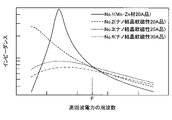
- FIG. 10 is a graph showing experimental results.
- No. 1 is the case of using Mn--Zn based toroidal cores in the toroidal coils 120a and 120b shown in FIG. No. 2 to No. 4 is a case where a nanocrystalline soft magnetic toroidal core is used in the toroidal coils 200a and 200b shown in FIG. No. 2 to No. 4, the rated current is changed to 20A, 25A and 30A, respectively.
- the Mn—Zn based toroidal core has a parallel resonance position on the high frequency side compared to the nanocrystalline soft magnetic toroidal core.
- the nanocrystalline soft magnetic toroidal core as the allowable power increases, the parallel resonance position shifts to the high frequency side.
- the impedance of the nanocrystalline soft magnetic toroidal core is smaller than that of the Mn--Zn based toroidal core.
- the nanocrystalline soft magnetic toroidal core has higher impedance. As described above, when the nanocrystalline soft magnetic toroidal core is used, the impedance in the high frequency region can be increased, so that a large noise suppression effect can be exhibited in a wide frequency region.
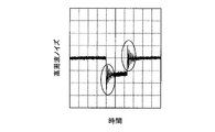
- FIG. 11 is a graph showing high-frequency noise waveforms when Mn—Zn based toroidal cores are used in the toroidal coils 120a and 120b shown in FIG.
- FIG. 12 is a graph showing high-frequency noise waveforms when the nanocrystalline soft magnetic toroidal cores are used in the toroidal coils 200a and 200b shown in FIG. 11 and 12, the horizontal axis indicates time, and the vertical axis indicates high frequency noise. In both cases, the high frequency noise was measured immediately before the heater control circuit of the heater power supply 54a.
- the same effects can be enjoyed. That is, the heat generation of the nanocrystalline soft magnetic toroidal core can be suppressed, and the size of the toroidal coils 200a and 200b can be reduced. Then, a high-inductance filter can be realized for the second high-frequency noise in the low-frequency region.
- the toroidal coils 200a and 200b can be miniaturized so that the nanocrystalline soft magnetic toroidal core satisfies the above formula (1). t ⁇ (ba) (1)
- the nanocrystalline soft magnetic toroidal core has a thickness t of 23.4 mm, an inner radius a of 21.4 mm, and an outer radius b of 40.6 mm.
- This satisfies equation (1).
- the thickness t of the single toroidal core is 13 mm
- the inner radius a is 19 mm
- the outer radius b is 30.5 mm.
- the housing 100 of the above embodiment has a substantially L-shape when viewed from the side, but may extend in the vertical direction as shown in FIG. 14 .
- the air-core coils 110a and 110b of the first filter 101 and the toroidal coils 120a and 120b of the second filter 102 are arranged vertically in this order from top to bottom. Even in such a case, the same effects (the first to third actions and effects) as in the above embodiment can be enjoyed.
Abstract
A plasma processing apparatus comprising: a processing vessel in which plasma processing is performed; an external circuit electrically connected, via a line, to an electrical member provided inside the processing vessel; and a filter unit provided on the line. The filter unit includes a first filter provided on the electrical member side, a second filter provided on the external circuit side and connected in series to the first filter, and a housing containing the first filter and the second filter. The first filter includes an air core coil. The second filter includes a coil with a toroidal core. The toroidal core is made of an Mn-Zn-based ferrite or a nanocrystal soft magnetic material.
Description
本開示は、プラズマ処理装置及びフィルタユニットに関する。
The present disclosure relates to a plasma processing apparatus and a filter unit.
特許文献1には、プラズマ処理装置において処理容器内の高周波電極その他の電気的部材から給電ラインや信号線等の線路上に入ってくる高周波ノイズを遮断するためのフィルタが開示されている。フィルタは、1個の空芯コイルと、空芯コイルを収容する円筒形の外導体とを有している。空芯コイルと外導体とは電気的に絶縁され、これら空芯コイルと外導体と間に形成される分布定数線路が、規則的な複数の周波数で並列共振をなしている。
Patent Literature 1 discloses a filter for blocking high-frequency noise entering a line such as a power supply line or a signal line from a high-frequency electrode or other electrical members in a processing container in a plasma processing apparatus. The filter has one air-core coil and a cylindrical outer conductor that accommodates the air-core coil. The air-core coil and the outer conductor are electrically insulated, and a distributed constant line formed between the air-core coil and the outer conductor performs parallel resonance at a plurality of regular frequencies.
本開示にかかる技術は、プラズマ処理装置において、フィルタユニットを用いて複数の周波数の高周波ノイズを適切に遮断しつつ、当該フィルタユニットを小型化する。
The technology according to the present disclosure uses a filter unit in a plasma processing apparatus to appropriately cut off high-frequency noise of a plurality of frequencies and downsize the filter unit.
本開示の一態様は、プラズマ処理装置であって、プラズマ処理が行われる処理容器と、前記処理容器の内部に設けられる電気的部材に線路を介して電気的に接続される外部回路と、前記線路に設けられるフィルタユニットと、を有し、前記フィルタユニットは、前記電気的部材側に設けられる第1のフィルタと、前記外部回路側に設けられ、前記第1のフィルタと直列に接続される第2のフィルタと、前記第1のフィルタと前記第2のフィルタを収容する筐体と、を有し、前記第1のフィルタは、空芯コイルを有し、前記第2のフィルタは、トロイダルコアを備えるコイルを有し、前記トロイダルコアは、Mn-Zn系のフェライト又はナノ結晶軟磁性材料からなる。
One aspect of the present disclosure is a plasma processing apparatus, comprising: a processing container in which plasma processing is performed; an external circuit electrically connected via a line to an electrical member provided inside the processing container; a filter unit provided on the line, wherein the filter unit is provided on the side of the electrical member, and the filter unit is provided on the side of the external circuit and connected in series with the first filter. a second filter, and a housing that accommodates the first filter and the second filter, the first filter having an air-core coil, and the second filter having a toroidal It has a coil with a core, said toroidal core being made of Mn—Zn based ferrite or nanocrystalline soft magnetic material.
本開示によれば、プラズマ処理装置において、フィルタユニットを用いて複数の周波数の高周波ノイズを適切に遮断しつつ、当該フィルタユニットを小型化することができる。
According to the present disclosure, in the plasma processing apparatus, the filter unit can be miniaturized while appropriately blocking high-frequency noise of multiple frequencies using the filter unit.
半導体デバイスの製造工程では、半導体ウェハ(以下、「ウェハ」という。)にプラズマ処理が行われる。プラズマ処理では、処理ガスを励起させることによりプラズマを生成し、当該プラズマによってウェハを処理する。このプラズマ処理では、ウェハ上のプラズマ密度分布の制御と共に、ウェハの温度又は温度分布の制御が重要である。ウェハの温度制御が適正に行われないと、プラズマ処理の均一性が確保できなくなり、半導体デバイスの製造歩留まりが低下するおそれがある。
In the manufacturing process of semiconductor devices, plasma processing is performed on semiconductor wafers (hereinafter referred to as "wafers"). In plasma processing, plasma is generated by exciting a processing gas, and the wafer is processed with the plasma. In this plasma processing, it is important to control the temperature or temperature distribution of the wafer as well as control the plasma density distribution on the wafer. If the temperature of the wafer is not properly controlled, the uniformity of plasma processing cannot be ensured, and the manufacturing yield of semiconductor devices may decrease.
プラズマ処理装置は、一般的に、チャンバ、ステージ、高周波(Radio Frequency:RF)電源を備える。一例では、高周波電源は、第1の高周波電源と第2の高周波電源を備える。第1の高周波電源は、チャンバ内のガスのプラズマを生成するために、第1の高周波電力を供給する。第2の高周波電源は、ウェハにイオンを引き込むために、バイアス用の第2の高周波電力を供給する。第2の高周波電力の周波数は、第1の高周波電力の周波数より高い。そして、これら高周波電力を用いて、チャンバの内部空間でプラズマが生成される。
A plasma processing apparatus generally includes a chamber, a stage, and a radio frequency (RF) power supply. In one example, the radio frequency power supply comprises a first radio frequency power supply and a second radio frequency power supply. A first RF power supply provides first RF power to generate a plasma of the gas within the chamber. A second RF power supply supplies second RF power for biasing to attract ions into the wafer. The frequency of the second high frequency power is higher than the frequency of the first high frequency power. Plasma is then generated in the interior space of the chamber using these high-frequency powers.
ステージは、チャンバ内に設けられる。ステージは、プラズマ空間に高周波を印加する高周波電極の機能と、ウェハを静電吸着等で保持する保持部の機能と、ウェハを伝熱で所定温度に制御する温度制御部の機能とを有している。温度制御機能に関しては、プラズマやチャンバ壁からの輻射熱の不均一性によるウェハへの入熱特性の分布や、ウェハ支持機構による熱分布を適切に補正できることが望まれている。
The stage is provided inside the chamber. The stage has a function of a high-frequency electrode that applies high-frequency waves to the plasma space, a function of a holding section that holds the wafer by electrostatic attraction or the like, and a function of a temperature control section that controls the wafer to a predetermined temperature by heat transfer. ing. As for the temperature control function, it is desired to appropriately correct the distribution of the heat input characteristics to the wafer due to the non-uniformity of the radiant heat from the plasma and the chamber wall, and the heat distribution due to the wafer support mechanism.
従来、ステージの温度、さらにはウェハの温度を制御するために、ステージに通電により発熱する発熱体を組み込んで当該発熱体を制御するヒータ方式が多く用いられている。しかしながら、ヒータ方式を用いた場合、高周波電源よりステージに供給された高周波電力の一部が、ノイズとして発熱体からヒータ給電ラインに入り込みやすい。高周波ノイズがヒータ給電ラインを通ってヒータ電源に到達すると、ヒータ電源の動作又は性能が害されるおそれがある。さらに、ヒータ給電ライン上で高周波の電流が流れると、高周波電力が無駄に消費される。このため、発熱体からの高周波のノイズを減衰させ、又は阻止するためのフィルタをヒータ給電ライン上に設けている。また、プラズマ処理装置では、上述したように周波数の異なる高周波電力が用いられる。かかる場合、フィルタは、これら異なる周波数の高周波ノイズを遮断する必要がある。
Conventionally, in order to control the temperature of the stage and further the temperature of the wafer, a heater system is often used in which a heating element that generates heat when energized is built into the stage and the heating element is controlled. However, when the heater method is used, part of the high-frequency power supplied from the high-frequency power source to the stage tends to enter the heater power supply line from the heating element as noise. High frequency noise reaching the heater power supply through the heater power supply line can impair the operation or performance of the heater power supply. Furthermore, when a high-frequency current flows on the heater power supply line, high-frequency power is wasted. For this reason, a filter for attenuating or blocking high-frequency noise from the heating element is provided on the heater power supply line. Further, in the plasma processing apparatus, high-frequency power with different frequencies is used as described above. In such cases, the filter needs to block high frequency noise at these different frequencies.
しかしながら、例えば特許文献1に開示されたフィルタは、1個の空芯コイルしか備えておらず、例えば第1の高周波電力のノイズしか遮断できず、第2の高周波電力のノイズは遮断できない。
However, the filter disclosed in Patent Document 1, for example, has only one air-core coil, and can block only the noise of the first high-frequency power, for example, and cannot block the noise of the second high-frequency power.
この点、第2の高周波電力のノイズを遮断するため、フィルタにトロイダルコイルをさらに設けることが考えられる。しかしながら、単にフィルタに空芯コイルとトロイダルコイルを設けただけでは、フィルタのサイズが大きくなる。その結果、プラズマ処理装置のレイアウト設計の自由度が低くなる。
In this respect, it is conceivable to further provide a toroidal coil in the filter in order to cut off the noise of the second high-frequency power. However, simply providing an air-core coil and a toroidal coil in the filter increases the size of the filter. As a result, the degree of freedom in layout design of the plasma processing apparatus is reduced.
ここで、上述したようにプラズマ処理においてはウェハの温度分布の制御が重要となるが、このウェハの温度分布を制御するため、ステージに複数の発熱体を設け、さらに複数の発熱体に接続される複数のヒータ給電ラインを設ける場合がある。かかる場合、チャンバの下部においてフィルタも複数設けられるが、チャンバの下部のスペースには限界がある。このため、上述したように各フィルタのサイズが大きくなると、複数のフィルタを配置することが困難になる。したがって、従来のフィルタには改善の余地がある。
Here, as described above, it is important to control the temperature distribution of the wafer in plasma processing. There may be multiple heater feed lines provided. In such a case, a plurality of filters are also provided in the lower part of the chamber, but the space in the lower part of the chamber is limited. Therefore, when the size of each filter increases as described above, it becomes difficult to arrange a plurality of filters. Therefore, conventional filters have room for improvement.
本開示にかかる技術は、フィルタユニットを用いて複数の周波数の高周波ノイズを適切に遮断しつつ、当該フィルタユニットを小型化する。以下、本実施形態にかかるプラズマ処理装置及びフィルタユニットについて、図面を参照しながら説明する。なお、本明細書及び図面において、実質的に同一の機能構成を有する要素においては、同一の符号を付することにより重複説明を省略する。
The technology according to the present disclosure uses a filter unit to appropriately cut off high-frequency noise of multiple frequencies while downsizing the filter unit. A plasma processing apparatus and a filter unit according to the present embodiment will be described below with reference to the drawings. In the present specification and drawings, elements having substantially the same functional configuration are denoted by the same reference numerals, thereby omitting redundant description.
<プラズマ処理装置>
先ず、本実施形態にかかるプラズマ処理装置について説明する。図1は、プラズマ処理装置1の構成の概略を示す縦断面図である。プラズマ処理装置1は、容量結合型のプラズマ処理装置である。プラズマ処理装置1では、ウェハWに対してプラズマ処理、例えばエッチングを行う。 <Plasma processing equipment>
First, the plasma processing apparatus according to this embodiment will be described. FIG. 1 is a vertical sectional view showing the outline of the configuration of theplasma processing apparatus 1. As shown in FIG. The plasma processing apparatus 1 is a capacitively coupled plasma processing apparatus. In the plasma processing apparatus 1, the wafer W is subjected to plasma processing such as etching.
先ず、本実施形態にかかるプラズマ処理装置について説明する。図1は、プラズマ処理装置1の構成の概略を示す縦断面図である。プラズマ処理装置1は、容量結合型のプラズマ処理装置である。プラズマ処理装置1では、ウェハWに対してプラズマ処理、例えばエッチングを行う。 <Plasma processing equipment>
First, the plasma processing apparatus according to this embodiment will be described. FIG. 1 is a vertical sectional view showing the outline of the configuration of the
図1に示すようにプラズマ処理装置1は、略円筒形状の処理容器としてのチャンバ10を有している。チャンバ10は、その内部においてプラズマが生成される処理空間Sを画成する。チャンバ10は、例えばアルミニウムからなる。チャンバ10は接地電位に接続されている。
As shown in FIG. 1, the plasma processing apparatus 1 has a chamber 10 as a substantially cylindrical processing container. Chamber 10 defines a processing space S within which a plasma is generated. The chamber 10 is made of aluminum, for example. Chamber 10 is connected to ground potential.
チャンバ10の内部には、ウェハWを載置するステージ11が収容されている。ステージ11は、下部電極(サセプタ)12、静電チャック13、及びエッジリング14を有している。なお、下部電極12の下面側には、例えばアルミニウムからなる電極プレート(図示せず)が設けられていてもよい。ステージ11は、下部電極12の下面側において、支持部材15に締結されて支持される。支持部材15は、チャンバ10の底部に設けられ、略円筒形状を有し、絶縁体からなる。また、支持部材15の外側には、当該支持部材15の外周に沿って支持部材16が設けられている。支持部材16は、チャンバ10の底部に設けられ、略円筒形状を有し、導電体からなる。
A stage 11 on which the wafer W is placed is housed inside the chamber 10 . The stage 11 has a lower electrode (susceptor) 12 , an electrostatic chuck 13 and an edge ring 14 . An electrode plate (not shown) made of aluminum, for example, may be provided on the lower surface side of the lower electrode 12 . The stage 11 is fastened to and supported by a support member 15 on the lower surface side of the lower electrode 12 . The support member 15 is provided at the bottom of the chamber 10, has a substantially cylindrical shape, and is made of an insulator. A support member 16 is provided outside the support member 15 along the outer periphery of the support member 15 . The support member 16 is provided at the bottom of the chamber 10, has a substantially cylindrical shape, and is made of a conductor.
下部電極12は、導電性の材料、例えばアルミニウム等の金属からなり、略円板形状を有している。
The lower electrode 12 is made of a conductive material, such as a metal such as aluminum, and has a substantially disk shape.
下部電極12の内部には、例えば円周方向に延びる環状の冷媒通路20が設けられている。冷媒通路20には、チラーユニット(図示せず)より冷媒供給管を介して冷媒、例えば冷却水CWが循環供給される。冷媒の温度によって下部電極12の温度を制御できる。また、下部電極12にウェハWを熱的に結合させるために、伝熱ガス供給部(図示せず)からの伝熱ガス、例えばHeガスが、ガス供給管と下部電極12の内部のガス通路21を介して、静電チャック13とウェハWとの接触界面に供給されるようになっている。
Inside the lower electrode 12, for example, an annular coolant passage 20 extending in the circumferential direction is provided. A coolant such as cooling water CW is circulatingly supplied to the coolant passage 20 from a chiller unit (not shown) through a coolant supply pipe. The temperature of the lower electrode 12 can be controlled by the temperature of the coolant. In order to thermally bond the wafer W to the lower electrode 12 , a heat transfer gas, such as He gas, from a heat transfer gas supply unit (not shown) is passed through the gas supply pipe and the gas passage inside the lower electrode 12 . 21, the contact interface between the electrostatic chuck 13 and the wafer W is supplied.
下部電極12には、第1の高周波電源30と第2の高周波電源31がそれぞれ、マッチングユニット32と給電棒33を介して電気的に接続されている。
A first high-frequency power source 30 and a second high-frequency power source 31 are electrically connected to the lower electrode 12 via a matching unit 32 and a power supply rod 33, respectively.
第1の高周波電源30は、主としてプラズマ発生用の第1の高周波電力HFを発生して、当該第1の高周波電力HFを下部電極12に供給する。第1の高周波電力HFの周波数は、13MHz~150MHzの範囲内の周波数であってよい。なお、第1の高周波電源30は、下部電極12に電気的に結合されていなくてもよくマッチングユニット32を介して上部電極である後述のシャワーヘッド60に結合されていてもよい。
The first high frequency power supply 30 mainly generates first high frequency power HF for plasma generation and supplies the first high frequency power HF to the lower electrode 12 . The frequency of the first high frequency power HF may be a frequency within the range of 13MHz to 150MHz. Note that the first high-frequency power source 30 may not be electrically coupled to the lower electrode 12 and may be coupled to a shower head 60, which is an upper electrode, via the matching unit 32, which will be described later.
第2の高周波電源31は、主としてウェハWにイオンを引き込むための第2の高周波電力(高周波バイアス電力)LFを発生して、当該第2の高周波電力LFを下部電極12に供給する。第2の高周波電力LFの周波数は、第1の高周波電力HFの周波数より低く、400kHz~13.56MHzの範囲内の周波数であってよい。なお、第2の高周波電源31に代えて、DC(Direct Current)パルス生成部を用いてもよい。この場合、パルス周波数は、400kHz~13.56MHzの範囲内の周波数であってよい。
The second high-frequency power supply 31 generates second high-frequency power (high-frequency bias power) LF mainly for drawing ions into the wafer W, and supplies the second high-frequency power LF to the lower electrode 12 . The frequency of the second high frequency power LF may be lower than the frequency of the first high frequency power HF and within the range of 400 kHz to 13.56 MHz. A DC (Direct Current) pulse generator may be used instead of the second high-frequency power supply 31 . In this case, the pulse frequency may be a frequency within the range of 400 kHz to 13.56 MHz.
マッチングユニット32には、第1の高周波電源30及び第2の高周波電源31とプラズマ負荷との間でインピーダンスの整合をとるための第1の整合器及び第2の整合器(図示せず)が収容されている。
The matching unit 32 includes a first matching box and a second matching box (not shown) for impedance matching between the first high-frequency power supply 30 and the second high-frequency power supply 31 and the plasma load. Contained.
給電棒33は、所定の外径を有する円筒形又は円柱形の導体からなる。給電棒33の上端は下部電極12の下面中心部に接続され、給電棒33の下端はマッチングユニット32に接続されている。また、チャンバ10の底部とマッチングユニット32との間には、給電棒33の周りを囲む円筒形の導体カバー34が設けられている。
The power supply rod 33 is made of a cylindrical or columnar conductor with a predetermined outer diameter. The upper end of the power supply rod 33 is connected to the center of the lower surface of the lower electrode 12 , and the lower end of the power supply rod 33 is connected to the matching unit 32 . A cylindrical conductor cover 34 surrounding the feed rod 33 is provided between the bottom of the chamber 10 and the matching unit 32 .
下部電極12の上面は、ウェハWと略同形状(円形)且つ略同サイズの中心領域であるウェハ載置部と、このウェハ載置部の外側に延在する環状のエッジリング載置部とに区画されている。ウェハ載置部には静電チャック13が設けられ、エッジリング載置部にはエッジリング14が載置される。
The upper surface of the lower electrode 12 is composed of a wafer mounting portion, which is a center region having substantially the same shape (circular shape) and size as the wafer W, and an annular edge ring mounting portion extending outside the wafer mounting portion. are divided into An electrostatic chuck 13 is provided on the wafer mounting portion, and an edge ring 14 is mounted on the edge ring mounting portion.
静電チャック13は、ウェハWをクーロン力により吸着保持可能に構成された部材である。エッジリング14は、静電チャック13の中央部の上面に載置されたウェハWを囲むように配置される、環状部材である。エッジリング14は、プラズマ処理(エッチング)の均一性を向上させるために設けられる。このため、エッジリング14は、エッチングに応じて適宜選択される材料から構成されており、例えばSiやSiCから構成され得る。
The electrostatic chuck 13 is a member configured to be able to attract and hold the wafer W by Coulomb force. The edge ring 14 is an annular member arranged so as to surround the wafer W placed on the upper surface of the central portion of the electrostatic chuck 13 . The edge ring 14 is provided to improve the uniformity of plasma processing (etching). For this reason, the edge ring 14 is made of a material appropriately selected according to etching, and can be made of Si or SiC, for example.
静電チャック13の内部には、DC電極40と、電気的部材としての発熱体50が設けられている。静電チャック13は、絶縁材料からなる絶縁材(誘電体)の間にDC電極40と発熱体50を挟んだ構成を有する。
A DC electrode 40 and a heating element 50 as an electrical member are provided inside the electrostatic chuck 13 . The electrostatic chuck 13 has a configuration in which a DC electrode 40 and a heating element 50 are sandwiched between insulating materials (dielectrics) made of an insulating material.
DC電極40には、チャンバ10の外部に配置される外付けの直流電源41が、スイッチ42、高抵抗値の抵抗43及びDC高圧線44を介して電気的に接続されている。直流電源41からの高圧の直流電圧がDC電極40に印加されることにより、クーロン力でウェハWを静電チャック13上に吸着保持できる。
An external DC power supply 41 arranged outside the chamber 10 is electrically connected to the DC electrode 40 via a switch 42 , a resistor 43 with a high resistance value, and a DC high voltage line 44 . By applying a high DC voltage from the DC power supply 41 to the DC electrode 40, the wafer W can be attracted and held on the electrostatic chuck 13 by Coulomb force.
発熱体50は、例えば螺旋状の抵抗発熱線からなり、静電チャック13の内部において内側の発熱線50aと外側の発熱線50bに分割されている。内側発熱線50aは、絶縁被覆された給電導体51a、フィルタユニット52a及び電気ケーブル53aを介して、チャンバ10の外部に配置されるヒータ電源54aに電気的に接続されている。外側発熱線50bは、絶縁被覆された給電導体51b、フィルタユニット52b及び電気ケーブル53bを介して、チャンバ10の外部に配置されるヒータ電源54bに電気的に接続されている。本実施形態では、給電導体51aと電気ケーブル53aが本開示における線路を構成し、給電導体51bと電気ケーブル53bが本開示における線路を構成する。また、ヒータ電源54a、54bはそれぞれ、外部回路としてのヒータ制御回路を有している。なお、フィルタユニット52a、52bの構成と作用については後述する。
The heating element 50 is composed of, for example, a spiral resistance heating wire, and is divided into an inner heating wire 50a and an outer heating wire 50b inside the electrostatic chuck 13. The inner heating wire 50a is electrically connected to a heater power supply 54a arranged outside the chamber 10 via an insulated feed conductor 51a, a filter unit 52a and an electric cable 53a. The outer heating wire 50b is electrically connected to a heater power supply 54b arranged outside the chamber 10 via an insulated power supply conductor 51b, a filter unit 52b and an electric cable 53b. In the present embodiment, the feeding conductor 51a and the electric cable 53a constitute the line in the present disclosure, and the feeding conductor 51b and the electric cable 53b constitute the line in the present disclosure. The heater power sources 54a and 54b each have a heater control circuit as an external circuit. The configuration and action of the filter units 52a and 52b will be described later.
なお、本実施形態の発熱体50の分割数は2つであったが、これに限定されない。例えば発熱体50を3つ以上に分割する場合、分割された発熱線のそれぞれに対して、フィルタユニットが設けられる。
Although the number of divisions of the heating element 50 in this embodiment is two, the number is not limited to this. For example, when dividing the heating element 50 into three or more, a filter unit is provided for each of the divided heating wires.
チャンバ10の天井部には、ステージ11と対向するように、シャワーヘッド60が設けられている。シャワーヘッド60は、処理空間Sに面して配置される電極板61と、電極板61の上方に設けられ、当該電極板61を着脱自在に支持する電極支持体62とを有している。電極板61は、下部電極12と一対の上部電極として機能する。後述するように第1の高周波電源30が下部電極12に電気的に結合されている場合には、シャワーヘッド60は、接地電位に接続される。電極板61は例えばSi、SiC、C等の導電体又は半導体からなり、電極支持体62は例えばアルマイト処理されたアルミニウムからなる。
A shower head 60 is provided on the ceiling of the chamber 10 so as to face the stage 11 . The shower head 60 has an electrode plate 61 arranged facing the processing space S, and an electrode support 62 provided above the electrode plate 61 and detachably supporting the electrode plate 61 . The electrode plate 61 functions as the lower electrode 12 and a pair of upper electrodes. When the first high-frequency power supply 30 is electrically coupled to the lower electrode 12 as will be described later, the showerhead 60 is connected to ground potential. The electrode plate 61 is made of, for example, a conductor or semiconductor such as Si, SiC, or C, and the electrode support 62 is made of, for example, alumite-treated aluminum.
電極支持体62の内部には、ガス室70が設けられている。ガス室70からは、下部電極12側に貫通する複数のガス吐出孔71が、電極支持体62の内部と電極板61の内部に設けられている。ガス室70の上部に設けられるガス導入口70aには、ガス供給部72からのガス供給管73が接続されている。プラズマ処理装置1においては、ガス供給部72からの処理ガスが、ガス供給管73、ガス室70及びガス吐出孔71を介して、処理空間S内にシャワー状に分散されて供給される。
A gas chamber 70 is provided inside the electrode support 62 . A plurality of gas ejection holes 71 are provided inside the electrode support 62 and inside the electrode plate 61 so as to penetrate from the gas chamber 70 to the lower electrode 12 side. A gas supply pipe 73 from a gas supply section 72 is connected to a gas introduction port 70 a provided in the upper portion of the gas chamber 70 . In the plasma processing apparatus 1 , the processing gas from the gas supply unit 72 is dispersed and supplied into the processing space S through the gas supply pipe 73 , the gas chamber 70 , and the gas discharge holes 71 in the form of a shower.
チャンバ10の下部には、チャンバ10の内壁と支持部材16との間に環状の排気路80が形成されている。排気路80の底面には排気口81が設けられており、処理空間Sは排気路80を介して排気口81に連通している。排気口81には、排気管82を介して排気装置83が接続されている。排気装置83は、例えばターボ分子ポンプなどの真空ポンプを有しており、処理空間Sを所望の真空度まで減圧することができる。
An annular exhaust path 80 is formed between the inner wall of the chamber 10 and the support member 16 at the bottom of the chamber 10 . An exhaust port 81 is provided on the bottom surface of the exhaust path 80 , and the processing space S communicates with the exhaust port 81 via the exhaust path 80 . An exhaust device 83 is connected to the exhaust port 81 via an exhaust pipe 82 . The exhaust device 83 has, for example, a vacuum pump such as a turbomolecular pump, and can depressurize the processing space S to a desired degree of vacuum.
また、チャンバ10の側壁には、ウェハWの搬入出口を開閉するゲートバルブ84が取り付けられている。
A gate valve 84 for opening and closing a loading/unloading port for the wafer W is attached to the side wall of the chamber 10 .
以上のプラズマ処理装置1には、制御部90が設けられている。制御部90は、例えばCPUやメモリ等を備えたコンピュータであり、プログラム格納部(図示せず)を有している。プログラム格納部には、プラズマ処理装置1におけるウェハWの処理を制御するプログラムが格納されている。なお、上記プログラムは、コンピュータに読み取り可能な記憶媒体Hに記録されていたものであって、当該記憶媒体Hから制御部90にインストールされたものであってもよい。また、上記記憶媒体Hは、一時的なものであっても非一時的なものであってもよい。
A controller 90 is provided in the plasma processing apparatus 1 described above. The control unit 90 is, for example, a computer having a CPU, memory, etc., and has a program storage unit (not shown). A program for controlling the processing of the wafer W in the plasma processing apparatus 1 is stored in the program storage unit. The program may be recorded in a computer-readable storage medium H and installed in the control unit 90 from the storage medium H. Further, the storage medium H may be temporary or non-temporary.
<プラズマ処理方法>
次に、以上のように構成されたプラズマ処理装置1を用いて行われるプラズマ処理、本実施形態ではエッチングについて説明する。 <Plasma treatment method>
Next, plasma processing performed using theplasma processing apparatus 1 configured as described above, which is etching in the present embodiment, will be described.
次に、以上のように構成されたプラズマ処理装置1を用いて行われるプラズマ処理、本実施形態ではエッチングについて説明する。 <Plasma treatment method>
Next, plasma processing performed using the
先ず、チャンバ10の内部にウェハWを搬入し、静電チャック13上にウェハWを載置する。その後、静電チャック13のDC電極40に直流電圧を印加することにより、ウェハWはクーロン力によって静電チャック13に静電吸着され、保持される。この際、ヒータ電源54a、54bをオンにして、内側発熱線50aと外側発熱線50bを各々独立したジュール熱で発熱させ、下部電極12上面の温度と温度分布を設定値に制御する。また、ウェハWの搬入後、排気装置83によってチャンバ10の内部を所望の真空度まで減圧する。
First, the wafer W is loaded into the chamber 10 and placed on the electrostatic chuck 13 . After that, by applying a DC voltage to the DC electrode 40 of the electrostatic chuck 13 , the wafer W is electrostatically attracted to and held by the electrostatic chuck 13 by Coulomb force. At this time, the heater power supplies 54a and 54b are turned on, the inner heating wire 50a and the outer heating wire 50b are independently heated by Joule heat, and the temperature and temperature distribution of the upper surface of the lower electrode 12 are controlled to set values. After loading the wafer W, the inside of the chamber 10 is decompressed to a desired degree of vacuum by the exhaust device 83 .
次に、ガス供給部72からシャワーヘッド60を介して処理空間Sに処理ガスを供給する。また、第1の高周波電源30によりプラズマ生成用の第1の高周波電力HFを下部電極12に供給し、処理ガスを励起させて、プラズマを生成する。この際、第2の高周波電源31によりイオン引き込み用の第2の高周波電力LFを供給する。そして、生成されたプラズマの作用によって、ウェハWにエッチングが施される。
Next, the processing gas is supplied from the gas supply unit 72 to the processing space S through the shower head 60 . Further, the first high-frequency power source 30 supplies the first high-frequency power HF for plasma generation to the lower electrode 12 to excite the processing gas and generate plasma. At this time, the second high-frequency power supply 31 supplies the second high-frequency power LF for attracting ions. Then, the wafer W is etched by the action of the generated plasma.
エッチングを終了する際には、先ず、第1の高周波電源30からの第1の高周波電力HFの供給、第2の高周波電源31からの第2の高周波電力LFの供給、及びガス供給部72による処理ガスの供給を停止する。次いで、ウェハWの裏面への伝熱ガスの供給を停止し、静電チャック13によるウェハWの吸着保持を停止する。その後、チャンバ10からウェハWを搬出して、ウェハWに対する一連のエッチングが終了する。
When etching is finished, first, the first high frequency power HF is supplied from the first high frequency power supply 30, the second high frequency power LF is supplied from the second high frequency power supply 31, and the gas supply unit 72 supplies Stop the process gas supply. Next, the supply of the heat transfer gas to the back surface of the wafer W is stopped, and the electrostatic chuck 13 stops holding the wafer W by attraction. After that, the wafer W is unloaded from the chamber 10, and a series of etchings for the wafer W is completed.
なお、このエッチング中、下部電極12に印加される第1の高周波電力HFの一部と第2の高周波電力LFの一部が、下部電極12の内部の内側発熱線50aと外側発熱線50bを介して給電導体51a、51bに高周波ノイズとして入り込んでくる。これら2周波の高周波ノイズのいずれかでもヒータ電源54a、54bに到達すれば、ヒータ電源54a、54bの動作又は性能が害されるおそれがある。なお、以下の説明においては、第1の高周波電力HFのノイズを「第1の高周波ノイズ」といい、第2の高周波電力LFのノイズを「第2の高周波ノイズ」という。
During this etching, part of the first high-frequency power HF and part of the second high-frequency power LF applied to the lower electrode 12 are applied to the inner heating wire 50a and the outer heating wire 50b inside the lower electrode 12. As a high-frequency noise, it enters into the power supply conductors 51a and 51b via. If either of these two frequencies of high frequency noise reaches the heater power supplies 54a, 54b, the operation or performance of the heater power supplies 54a, 54b may be impaired. In the following description, the noise of the first high frequency power HF is called "first high frequency noise", and the noise of the second high frequency power LF is called "second high frequency noise".
この点、上述したように、ヒータ電源54a、54bと内側発熱線50a及び外側発熱線50bとを電気的に結ぶ給電ライン上にフィルタユニット52a、52bが設けられている。これらのフィルタユニット52a、52bは、以下に詳しく述べるように、内側発熱線50aと外側発熱線50bから給電ライン上に入ってくる第1の高周波ノイズと第2の高周波ノイズのいずれに対しても、インピーダンスの十分に高いフィルタ遮断機能を低消費電力で効率的にかつ安定確実に発揮する。これにより、本実施形態のプラズマ処理装置1は、ヒータ方式のウェハ温度制御機能を向上させることができる。また、チャンバ10から下部電極12の内部の発熱体50を介して給電ライン上に第1の高周波電力HFと第2の高周波電力LFが漏れるのを効果的に抑制し、プラズマプロセスの再現性及び信頼性を向上させることができる。
In this regard, as described above, the filter units 52a and 52b are provided on the feeder lines that electrically connect the heater power supplies 54a and 54b to the inner heating wire 50a and the outer heating wire 50b. As described in detail below, these filter units 52a and 52b are effective against both the first high-frequency noise and the second high-frequency noise entering the power supply line from the inner heating wire 50a and the outer heating wire 50b. , the filter cutoff function with sufficiently high impedance is efficiently, stably and reliably demonstrated with low power consumption. Thereby, the plasma processing apparatus 1 of the present embodiment can improve the heater-type wafer temperature control function. In addition, it effectively suppresses leakage of the first high-frequency power HF and the second high-frequency power LF from the chamber 10 onto the power supply line via the heating element 50 inside the lower electrode 12, thereby improving the reproducibility of the plasma process. Reliability can be improved.
<フィルタユニットの回路構成>
次に、上述したフィルタユニット52a、52bの回路構成(等価回路)について説明する。本実施形態では、発熱体50の内側発熱線50aと外側発熱線50bのそれぞれに対して実質的に同一の回路構成を有するフィルタユニット52a、52bを接続し、内側発熱線50aと外側発熱線50bの発熱量又は発熱温度を独立に制御するようにしている。以下の説明においては、フィルタユニット52aの回路構成について説明するが、フィルタユニット52bの回路構成も同様である。図2は、フィルタユニット52aの回路構成を示す説明図である。 <Circuit Configuration of Filter Unit>
Next, the circuit configuration (equivalent circuit) of the filter units 52a and 52b described above will be described. In this embodiment, filter units 52a and 52b having substantially the same circuit configuration are connected to the inner heating wire 50a and the outer heating wire 50b of the heating element 50, respectively. The calorific value or the calorific temperature is independently controlled. In the following description, the circuit configuration of the filter unit 52a will be described, but the circuit configuration of the filter unit 52b is the same. FIG. 2 is an explanatory diagram showing the circuit configuration of the filter unit 52a.
次に、上述したフィルタユニット52a、52bの回路構成(等価回路)について説明する。本実施形態では、発熱体50の内側発熱線50aと外側発熱線50bのそれぞれに対して実質的に同一の回路構成を有するフィルタユニット52a、52bを接続し、内側発熱線50aと外側発熱線50bの発熱量又は発熱温度を独立に制御するようにしている。以下の説明においては、フィルタユニット52aの回路構成について説明するが、フィルタユニット52bの回路構成も同様である。図2は、フィルタユニット52aの回路構成を示す説明図である。 <Circuit Configuration of Filter Unit>
Next, the circuit configuration (equivalent circuit) of the
図2に示すようにフィルタユニット52aは、筐体100の内部に第1のフィルタ101と第2のフィルタ102を収容した構成を有している。筐体100は導電性を有し、接地されている。第1のフィルタ101と第2のフィルタ102は、給電導体51aと電気ケーブル53aを接続する給電ライン103上において、直列に接続されている。第1のフィルタ101は内側発熱線50a側に設けられ、第2のフィルタ102はヒータ電源54a側に設けられている。
As shown in FIG. 2, the filter unit 52a has a configuration in which a first filter 101 and a second filter 102 are housed inside a housing 100. As shown in FIG. The housing 100 is conductive and grounded. The first filter 101 and the second filter 102 are connected in series on the feeder line 103 connecting the feeder conductor 51a and the electric cable 53a. The first filter 101 is provided on the inner heating wire 50a side, and the second filter 102 is provided on the heater power supply 54a side.
第1のフィルタ101は、例えば3つのリアクタンス素子を有し、すなわち2つの空芯コイル110a、110bと1つの第1のコンデンサ111を有している。空芯コイル110a、110bは内側発熱線50a側からこの順で直列に接続されている。第1のコンデンサ111は、一方が給電ライン103において空芯コイル110bより後述のトロイダルコイル120a側の端子112に電気的に接続されており、もう一方が筐体100と同電位となるよう接地されている。
The first filter 101 has, for example, three reactance elements, namely two air- core coils 110a, 110b and one first capacitor 111. The air- core coils 110a and 110b are connected in series in this order from the inner heating wire 50a side. One of the first capacitors 111 is electrically connected to a terminal 112 on the side of the toroidal coil 120a, which will be described later, from the air-core coil 110b in the feeder line 103, and the other is grounded so as to have the same potential as the housing 100. ing.
第2のフィルタ102は、例えば3つのリアクタンス素子を有し、すなわち2つのトロイダルコイル120a、120bと1つの第2のコンデンサ121を有している。トロイダルコイル120a、120bは空芯コイル110b側からこの順で直列に接続されている。第2のコンデンサ121は、一方が給電ライン103においてトロイダルコイル120bよりヒータ電源54a側の端子122に電気的に接続されており、もう一方が筐体100と同電位となるよう接地されている。トロイダルコイル120a、120bのコア部(以下、「トロイダルコア」という。)は、Mn-Zn系のフェライトからなる。
The second filter 102 has, for example, three reactance elements, namely two toroidal coils 120 a, 120 b and one second capacitor 121 . The toroidal coils 120a and 120b are connected in series in this order from the air core coil 110b side. One of the second capacitors 121 is electrically connected to a terminal 122 on the heater power supply 54a side of the toroidal coil 120b in the feeder line 103, and the other is grounded so as to have the same potential as the housing 100. Core portions of the toroidal coils 120a and 120b (hereinafter referred to as “toroidal cores”) are made of Mn—Zn ferrite.
<フィルタユニットの物理的構造>
次に、上述したフィルタユニット52a、52bの物理的構造について説明する。以下の説明においては、フィルタユニット52aの物理的構造について説明するが、フィルタユニット52bの物理的構造も同様である。図3は、フィルタユニット52aの物理的構造を示す縦断面図である。 <Physical Structure of Filter Unit>
Next, the physical structure of the filter units 52a and 52b described above will be described. In the following description, the physical structure of the filter unit 52a will be described, but the physical structure of the filter unit 52b is the same. FIG. 3 is a longitudinal sectional view showing the physical structure of the filter unit 52a.
次に、上述したフィルタユニット52a、52bの物理的構造について説明する。以下の説明においては、フィルタユニット52aの物理的構造について説明するが、フィルタユニット52bの物理的構造も同様である。図3は、フィルタユニット52aの物理的構造を示す縦断面図である。 <Physical Structure of Filter Unit>
Next, the physical structure of the
図3に示すようにフィルタユニット52aは、筐体100を有している。上述したように、フィルタユニット52bもフィルタユニット52aと同じ構造を有し、筐体100を有している。換言すれば、各フィルタユニット52a、52bに設けられた筐体100が、内側発熱線50aと外側発熱線50bを区画して分割された、異なるヒータ領域に対応している。
The filter unit 52a has a housing 100 as shown in FIG. As described above, the filter unit 52b also has the same structure as the filter unit 52a and has the housing 100. As shown in FIG. In other words, the housing 100 provided in each of the filter units 52a and 52b corresponds to different heater regions divided by dividing the inner heating wire 50a and the outer heating wire 50b.
筐体100は、その内部に設けられた各部材から絶縁距離、例えば10mm以上離して設けられている。内部部材である空芯コイル110a、110b、トロイダルコイル120a、120b、連結ケーブル130等は、高周波放射の漏洩を抑制するため、高耐圧を有するためである。
The housing 100 is provided at an insulating distance, for example, 10 mm or more from each member provided inside. This is because the air- core coils 110a and 110b, the toroidal coils 120a and 120b, the connecting cable 130, etc., which are internal members, have high withstand voltage in order to suppress leakage of high-frequency radiation.
筐体100は、側面視において略L字型を有している。すなわち、筐体100は、鉛直方向(上下方向)に延伸する鉛直延伸部100aと、鉛直延伸部100aの下端から水平方向に延伸する水平延伸部100bとを有している。なお、筐体100は、上述したように導電性を有し、例えばアルミニウムからなり、接地されている。
The housing 100 has a substantially L shape when viewed from the side. That is, the housing 100 has a vertically extending portion 100a extending in the vertical direction (vertical direction) and a horizontally extending portion 100b extending horizontally from the lower end of the vertically extending portion 100a. The housing 100 is electrically conductive as described above, is made of aluminum, for example, and is grounded.
筐体100の内部には、発熱体50の内側発熱線50aから見て、前段に第1のフィルタ101の空芯コイル110a、110bが配置され、後段に第2のフィルタ102のトロイダルコイル120a、120bが配置されている。前段の空芯コイル110a、110bは、鉛直延伸部100aの内部において、内側発熱線50a側から、すなわち上方から下方に鉛直方向にこの順で並べて配置されている。後段のトロイダルコイル120a、120bは、水平延伸部100bの内部において、空芯コイル110b側から水平方向にこの順で並べて配置されている。空芯コイル110a、110bの鉛直軸と、トロイダルコイル120aの鉛直軸と、トロイダルコイル120bの鉛直軸とは、異なっている。このように鉛直軸が異なっているため、例えば空芯コイル110a、110bの鉛直軸と、トロイダルコイル120a、120bの鉛直軸とが同軸である場合に比べて、プラズマ処理時の電界の影響を受け難くすることができる。なお、以下の説明においては、内側発熱線50aから見た前段と後段をそれぞれ、単に「前段」と「後段」という場合がある。
Inside the housing 100, when viewed from the inner heating wire 50a of the heating element 50, the air- core coils 110a and 110b of the first filter 101 are arranged in the front stage, and the toroidal coil 120a of the second filter 102 is arranged in the rear stage. 120b are arranged. The air- core coils 110a and 110b of the previous stage are arranged side by side in this order in the vertical direction from the inner heating wire 50a side, that is, from the top to the bottom inside the vertically extending portion 100a. The latter toroidal coils 120a and 120b are horizontally arranged in this order from the side of the air-core coil 110b inside the horizontally extending portion 100b. The vertical axis of the air- core coils 110a and 110b, the vertical axis of the toroidal coil 120a, and the vertical axis of the toroidal coil 120b are different. Since the vertical axes are different in this way, the effect of the electric field during plasma processing is greater than when the vertical axes of the air- core coils 110a and 110b and the vertical axes of the toroidal coils 120a and 120b are coaxial, for example. can be made difficult. In addition, in the following description, the front stage and the rear stage viewed from the inner heating wire 50a may be simply referred to as the "front stage" and the "back stage", respectively.
空芯コイル110bとトロイダルコイル120aは、連結ケーブル130で接続されている。連結ケーブル130は、鉛直延伸部100aと水平延伸部100bに亘って設けられている。連結ケーブル130の上端部は後述する基板144に固定され、下端部は後述する基板160に固定されている。なお、フィルタユニット52aの連結ケーブル130の長さと、フィルタユニット52bの連結ケーブル130の長さとは同じである。
The air-core coil 110b and the toroidal coil 120a are connected by a connecting cable 130. The connection cable 130 is provided over the vertically extending portion 100a and the horizontally extending portion 100b. The connection cable 130 has an upper end fixed to a substrate 144 described later, and a lower end fixed to a substrate 160 described later. The length of the connection cable 130 of the filter unit 52a and the length of the connection cable 130 of the filter unit 52b are the same.
空芯コイル110a、110bは、エッジワイズ巻のコイルである。空芯コイル110a、110bは、当該空芯コイル110a、110bのコイル導体が軸方向(鉛直方向)に重なり合って並進しながら各々複数段階に可変の巻線ピッチで螺旋状に巻かれている。巻線ピッチは、任意に設計できるが、例えば特開2015-173027号公報に開示されているように、高周波用フィルタとしての特性を確保するように設計される。
The air- core coils 110a and 110b are edgewise wound coils. The coil conductors of the air- core coils 110a and 110b are overlapped in the axial direction (vertical direction) and translated in the air- core coils 110a and 110b. Although the winding pitch can be arbitrarily designed, it is designed to ensure the characteristics of a high-frequency filter, as disclosed in Japanese Unexamined Patent Application Publication No. 2015-173027, for example.
空芯コイル110a、110bはそれぞれ、略円筒状の支持部材140a、140bに支持されている。支持部材140a、140bは、鉛直延伸部100aの内側面に支持されている。支持部材140a、140bの内側面には凹凸が形成され、当該凹凸に空芯コイル110a、110bの巻線部が固定される。また、支持部材140a、140bは、例えば樹脂からなる。
The air- core coils 110a and 110b are respectively supported by substantially cylindrical support members 140a and 140b. The support members 140a and 140b are supported on the inner surface of the vertically extending portion 100a. Concavities and convexities are formed on the inner surfaces of the support members 140a and 140b, and the winding portions of the air- core coils 110a and 110b are fixed to the concavities and convexities. Further, the support members 140a and 140b are made of resin, for example.
前段の空芯コイル110aの上端端子は、金属ブロック141に固定されている。金属ブロック141は、筐体100の上方に設けられた絶縁体142に覆われ、給電導体51aに接続されている。空芯コイル110aの下端端子は、基板143に固定されている。
The upper end terminal of the air-core coil 110a in the front stage is fixed to the metal block 141. The metal block 141 is covered with an insulator 142 provided above the housing 100 and connected to the feed conductor 51a. A lower end terminal of the air core coil 110 a is fixed to the substrate 143 .
後段の空芯コイル110bの上端端子は、基板143に固定されている。すなわち、基板143には、空芯コイル110aの下端端子と空芯コイル110bの上端端子が固定され、基板143を介して空芯コイル110a、110bは直列に接続されている。空芯コイル110bの下端端子は、基板144に固定されている。
The upper end terminal of the air-core coil 110b in the latter stage is fixed to the substrate 143. That is, the lower end terminal of the air core coil 110a and the upper end terminal of the air core coil 110b are fixed to the substrate 143, and the air core coils 110a and 110b are connected in series via the substrate 143. FIG. A lower end terminal of the air core coil 110 b is fixed to the substrate 144 .
トロイダルコイル120a、120bはそれぞれ、Mn-Zn系のフェライトからなるトロイダルコア150に、例えば銅線からなるコイル導体151を螺旋状に巻き付けた構成を有している。図4に示すようにトロイダルコア150において内半径をa、外半径をb、厚みをtとした場合に、厚みtは下記式(1)を満たしている。例えば、特開2014-56706号公報や特開2014-229565号公報には、一般的な単体のトロイダルコアとして、t≒(b-a)の関係が開示されている。この点、本実施形態では、下記式(1)を満たしており、すなわちtが大きい又は(b-a)が小さいので、トロイダルコア150の透磁率を大きくすることができる。
t≧(b-a) ・・・(1) Each of the toroidal coils 120a and 120b has a structure in which a coil conductor 151 made of, for example, copper wire is helically wound around a toroidal core 150 made of Mn—Zn ferrite. As shown in FIG. 4, in the toroidal core 150, when the inner radius is a, the outer radius is b, and the thickness is t, the thickness t satisfies the following formula (1). For example, JP-A-2014-56706 and JP-A-2014-229565 disclose the relationship t≈(ba) for a general single toroidal core. In this regard, in this embodiment, the following formula (1) is satisfied, that is, t is large or (ba) is small, so the magnetic permeability of the toroidal core 150 can be increased.
t≧(ba) (1)
t≧(b-a) ・・・(1) Each of the
t≧(ba) (1)
図3に示すようにトロイダルコイル120a、120bはそれぞれ、基板160の下面に設けられている。トロイダルコイル120a、120bは、基板160に形成されたパターンで直列に接続されている。基板160は、側面視においてロの字形状を有する支持部材161に支持され、支持部材161は水平延伸部100bの底面に固定されている。また、基板160は、例えばガラスエポキシ系からなる。
As shown in FIG. 3, the toroidal coils 120a and 120b are provided on the lower surface of the substrate 160, respectively. The toroidal coils 120 a and 120 b are connected in series in a pattern formed on the substrate 160 . The substrate 160 is supported by a support member 161 having a square shape in side view, and the support member 161 is fixed to the bottom surface of the horizontally extending portion 100b. Further, the substrate 160 is made of glass epoxy, for example.
基板160の表面には、第1のフィルタ101の第1のコンデンサ111が設けられている。第1のコンデンサ111は、基板160の表面に設けられた連結ケーブル130の端子及びトロイダルコイル120a間と、グランドとの間に設けられている。
A first capacitor 111 of the first filter 101 is provided on the surface of the substrate 160 . The first capacitor 111 is provided between the terminal of the connection cable 130 provided on the surface of the substrate 160 and the toroidal coil 120a, and between the ground.
また、基板160の表面には、第2のフィルタ102の第2のコンデンサ121が設けられている。第2のコンデンサ121は、トロイダルコイル120b及び基板160の表面に設けられた電気ケーブル53aの端子間と、グランドとの間に設けられている。
Also, the second capacitor 121 of the second filter 102 is provided on the surface of the substrate 160 . The second capacitor 121 is provided between the toroidal coil 120b and the terminals of the electrical cable 53a provided on the surface of the substrate 160 and between the ground.
筐体100の底面外側には、当該筐体100の内部にエアを供給するファン170が設けられている。筐体100の底面においてトロイダルコイル120a、120bの下方には複数のパンチ穴が形成され、さらに筐体100の鉛直延伸部の100a上端にも複数のパンチ穴が形成さている。ファン170から筐体100の内部に供給されたエアは、水平延伸部100bと鉛直延伸部100aを順に流通し、筐体100の上部から外部に流出する。この際、トロイダルコイル120a、120bと空芯コイル110a、110bがエアによって冷却される。
A fan 170 that supplies air to the inside of the housing 100 is provided on the outside of the bottom surface of the housing 100 . A plurality of punched holes are formed in the bottom surface of the housing 100 below the toroidal coils 120a and 120b, and a plurality of punched holes are also formed in the upper end of the vertically extending portion 100a of the housing 100. FIG. The air supplied from the fan 170 to the inside of the housing 100 sequentially flows through the horizontally extending portion 100b and the vertically extending portion 100a, and flows out from the upper portion of the housing 100 to the outside. At this time, the toroidal coils 120a, 120b and the air core coils 110a, 110b are cooled by air.
<フィルタユニットの作用及び効果>
次に、以上のように構成されたフィルタユニット52a、52bの作用及び効果について説明する。以下の説明においては、フィルタユニット52aの作用及び効果について説明するが、フィルタユニット52bの作用及び効果も同様である。 <Action and effect of the filter unit>
Next, the operation and effects of the filter units 52a and 52b configured as described above will be described. In the following description, the action and effect of the filter unit 52a will be explained, but the action and effect of the filter unit 52b are the same.
次に、以上のように構成されたフィルタユニット52a、52bの作用及び効果について説明する。以下の説明においては、フィルタユニット52aの作用及び効果について説明するが、フィルタユニット52bの作用及び効果も同様である。 <Action and effect of the filter unit>
Next, the operation and effects of the
[第1の作用及び効果]
本実施形態のフィルタユニット52aにおいては、トロイダルコイル120a、120bのトロイダルコア150はMn-Zn系のフェライトからなる。ここで、一般的なNi-Zn系のフェライトからなるトロイダルコアを比較例とする。以下の説明においては、本実施形態のMn-Zn系のフェライトからなるトロイダルコア150を「Mn-Zn系トロイダルコア」といい、比較例のNi-Zn系のフェライトからなるトロイダルコアを「Ni-Zn系トロイダルコア」という場合がある。 [First action and effect]
In thefilter unit 52a of the present embodiment, the toroidal cores 150 of the toroidal coils 120a and 120b are made of Mn--Zn ferrite. Here, a toroidal core made of general Ni—Zn ferrite is used as a comparative example. In the following description, the toroidal core 150 made of Mn—Zn ferrite of the present embodiment is referred to as “Mn—Zn toroidal core”, and the toroidal core made of Ni—Zn ferrite of the comparative example is referred to as “Ni— Zn-based toroidal core".
本実施形態のフィルタユニット52aにおいては、トロイダルコイル120a、120bのトロイダルコア150はMn-Zn系のフェライトからなる。ここで、一般的なNi-Zn系のフェライトからなるトロイダルコアを比較例とする。以下の説明においては、本実施形態のMn-Zn系のフェライトからなるトロイダルコア150を「Mn-Zn系トロイダルコア」といい、比較例のNi-Zn系のフェライトからなるトロイダルコアを「Ni-Zn系トロイダルコア」という場合がある。 [First action and effect]
In the
Ni-Zn系トロイダルコアは、高周波領域、例えば1MHz~100MHzのノイズ抑制効果が大きく、例えば3000H/m以下の低透磁率である。このように低透磁率であると、許容損失(耐圧)が不足するため、周波数の低い第2の高周波電力LFを下部電極12に供給すると、Ni-Zn系トロイダルコアが発熱するおそれがある。また、透磁率を高くするため、Ni-Zn系トロイダルコアを直列接続し、又はスタック数(重ね合わせ数)多くする場合があるが、かかる場合、トロイダルコイルが大型化してしまう。
The Ni--Zn toroidal core has a large noise suppression effect in the high frequency range, for example, 1 MHz to 100 MHz, and has a low magnetic permeability of, for example, 3000 H/m or less. With such a low magnetic permeability, the allowable loss (breakdown voltage) is insufficient, so if the lower electrode 12 is supplied with the second high-frequency power LF with a low frequency, the Ni—Zn toroidal core may generate heat. In order to increase the magnetic permeability, the Ni—Zn toroidal cores are connected in series or the number of stacks (the number of layers) is increased, but in such a case, the toroidal coil becomes large.
これに対して、Mn-Zn系トロイダルコアは、低周波領域、例えば10MHz以下のノイズ抑制効果が大きく、例えば6000H/m以上の高透磁率である。したがって、周波数の低い第2の高周波電力LFを下部電極12に供給しても、Mn-Zn系トロイダルコアが発熱するのを抑制することができる。
On the other hand, the Mn-Zn toroidal core has a large noise suppression effect in the low frequency range, for example, 10 MHz or less, and has a high magnetic permeability of, for example, 6000 H/m or more. Therefore, even if the lower electrode 12 is supplied with the second high-frequency power LF having a low frequency, it is possible to suppress the heat generation of the Mn--Zn based toroidal core.
また、Mn-Zn系トロイダルコアは、低周波領域で高透磁率であるため、Ni-Zn系トロイダルコアを用いた場合のように直列接続する必要がなく、またスタック数を低減することができる。したがって、トロイダルコイル120a、120bを小型化することができる。具体的には、上述したようにトロイダルコア150が式(1)を満たすように、トロイダルコイル120a、120bを小型化することができる。さらには、本発明者らが鋭意検討した結果、Mn-Zn系トロイダルコアを用いた場合、Ni-Zn系トロイダルコアに比べて、トロイダルコイル120a、120bの大きさを約半分まで小型化することができた。そして、このようにトロイダルコイル120a、120bを小型化して、さらにはフィルタユニット52aを小型化することができるので、プラズマ処理装置1のレイアウト設計、特にチャンバ10の下部のレイアウト設計の自由度を向上させることができる。その結果、チャンバ10の下部が限られたスペースであっても、複数、本実施形態では2つのフィルタユニット52a、52bを適切に設けることができる。
In addition, since the Mn--Zn toroidal core has a high magnetic permeability in the low frequency region, there is no need to connect in series unlike the Ni--Zn toroidal core, and the number of stacks can be reduced. . Therefore, the toroidal coils 120a and 120b can be miniaturized. Specifically, the toroidal coils 120a and 120b can be downsized so that the toroidal core 150 satisfies the formula (1) as described above. Furthermore, as a result of extensive studies by the present inventors, when using a Mn--Zn based toroidal core, the size of the toroidal coils 120a and 120b can be reduced to about half compared to a Ni--Zn based toroidal core. was made. Since the toroidal coils 120a and 120b can be miniaturized and the filter unit 52a can be miniaturized in this way, the degree of freedom in the layout design of the plasma processing apparatus 1, especially in the layout design of the lower part of the chamber 10 is improved. can be made As a result, even if the lower part of the chamber 10 has a limited space, a plurality of, in this embodiment, two filter units 52a and 52b can be appropriately provided.
なお、一例において、Mn-Zn系トロイダルコアであるトロイダルコア150の厚みtは12.7mm、内半径aは9.5mm、外半径bは19.05mmである。これは式(1)を満たす。そして絶縁距離を10mmとすると、トロイダルコイル120a、120bの厚みは、35.4mm(=12.7×2+10)となる。また、トロイダルコイル120a、120bの平面視長さは、38.1mm(=19.05×2)となる。
一方、Ni-Zn系トロイダルコアを用いた場合、単体のトロイダルコアの厚みtは13mm、内半径aは19mm、外半径bは30.5mmである。例えば、このトロイダルコアを7個積層したもの(7スタック)を、厚み方向に2個配置し、平面視において4配置して、合計8個用いる。かかる場合、8個のトロイダルコイルの厚みは、182mm(=13×7×2)となる。また、8個のトロイダルコイルの平面視長さは、132mm(=30.5×2×2+10)となる。
したがって、本実施形態のようにMn-Zn系トロイダルコアを用いた場合、Ni-Zn系トロイダルコアに比べて、厚さが0.20倍、平面視長さが0.29倍になり、トロイダルコイル120a、120bを小型化することができる。 In one example, thetoroidal core 150, which is a Mn--Zn based toroidal core, has a thickness t of 12.7 mm, an inner radius a of 9.5 mm, and an outer radius b of 19.05 mm. This satisfies equation (1). Assuming that the insulation distance is 10 mm, the thickness of the toroidal coils 120a and 120b is 35.4 mm (=12.7×2+10). Also, the length of the toroidal coils 120a and 120b in plan view is 38.1 mm (=19.05×2).
On the other hand, when a Ni—Zn based toroidal core is used, the thickness t of the single toroidal core is 13 mm, the inner radius a is 19 mm, and the outer radius b is 30.5 mm. For example, seven toroidal cores (7 stacks) are arranged in two in the thickness direction and four in plan view, for a total of eight. In this case, the thickness of the eight toroidal coils is 182 mm (=13×7×2). Also, the length of the eight toroidal coils in plan view is 132 mm (=30.5×2×2+10).
Therefore, when the Mn--Zn based toroidal core is used as in the present embodiment, the thickness is 0.20 times and the planar view length is 0.29 times as large as the Ni--Zn based toroidal core. Coils 120a and 120b can be miniaturized.
一方、Ni-Zn系トロイダルコアを用いた場合、単体のトロイダルコアの厚みtは13mm、内半径aは19mm、外半径bは30.5mmである。例えば、このトロイダルコアを7個積層したもの(7スタック)を、厚み方向に2個配置し、平面視において4配置して、合計8個用いる。かかる場合、8個のトロイダルコイルの厚みは、182mm(=13×7×2)となる。また、8個のトロイダルコイルの平面視長さは、132mm(=30.5×2×2+10)となる。
したがって、本実施形態のようにMn-Zn系トロイダルコアを用いた場合、Ni-Zn系トロイダルコアに比べて、厚さが0.20倍、平面視長さが0.29倍になり、トロイダルコイル120a、120bを小型化することができる。 In one example, the
On the other hand, when a Ni—Zn based toroidal core is used, the thickness t of the single toroidal core is 13 mm, the inner radius a is 19 mm, and the outer radius b is 30.5 mm. For example, seven toroidal cores (7 stacks) are arranged in two in the thickness direction and four in plan view, for a total of eight. In this case, the thickness of the eight toroidal coils is 182 mm (=13×7×2). Also, the length of the eight toroidal coils in plan view is 132 mm (=30.5×2×2+10).
Therefore, when the Mn--Zn based toroidal core is used as in the present embodiment, the thickness is 0.20 times and the planar view length is 0.29 times as large as the Ni--Zn based toroidal core.
以上のように本実施形態のトロイダルコイル120a、120bを用いた場合、Mn-Zn系トロイダルコア(トロイダルコア150)の発熱を抑制すると共に、トロイダルコイル120a、120bを小型化することができる。そして、低周波領域の第2の高周波ノイズに対して、高インダクタンスのフィルタを実現することが可能となる。
As described above, when the toroidal coils 120a and 120b of the present embodiment are used, heat generation of the Mn--Zn toroidal core (toroidal core 150) can be suppressed and the size of the toroidal coils 120a and 120b can be reduced. Then, it becomes possible to realize a high-inductance filter for the second high-frequency noise in the low-frequency region.
なお、トロイダルコイルが発熱するリスクは、例えば以下の原因によるものである。1つ目は、例えばヒータ電源から給電ラインに流れる電流により、Ni-Zn系トロイダルコアに巻き付けられたコイル導体(銅線)が発熱する銅損発熱である。2つ目は、例えばプラズマ側から給電ラインに引き込む電流により、コイル導体(銅線)が発熱する銅損発熱である。3つ目は、例えばプラズマ側から給電ラインに伝搬する伝導性ノイズにより、Ni-Zn系トロイダルコアに渦電流、ヒステリシス損が発生して発熱する鉄損発熱である。
The risk of the toroidal coil heating up is due to, for example, the following causes. The first is copper loss heat generation, in which a coil conductor (copper wire) wound around a Ni—Zn toroidal core heats up due to current flowing from a heater power supply to a power supply line, for example. The second is copper loss heat generation in which the coil conductor (copper wire) heats up due to, for example, a current drawn from the plasma side to the power supply line. The third is iron loss heat generation, which is generated by eddy current and hysteresis loss in the Ni--Zn based toroidal core due to conductive noise propagating from the plasma side to the feed line, for example.
このうち、1つ目と2つ目のコイル導体の銅損に対しては、給電ラインに流れる電流値に対して、許容できるコイル導体の線径(断面積)を選定すればよい。
Among these, for the copper loss of the first and second coil conductors, the wire diameter (cross-sectional area) of the coil conductors that is allowable for the current value flowing in the power supply line should be selected.
また、3つ目のトロイダルコアの鉄損に対しては、Mn-Zn系トロイダルコアを用いた場合、低周波領域では高透磁率であるため、鉄損は抑えられる。一方、高周波領域では透磁率が低下するため、Mn-Zn系トロイダルコアを用いた場合でも鉄損が大きくなる。そこで、本実施形態のトロイダルコイル120a、120bでは、トロイダルコイル120a、120bを後段に配置し、空芯コイル110a、110bを前段に配置する構成を有する。かかる場合、高周波領域である第1の高周波ノイズを空芯コイル110a、110bで遮断するため、Mn-Zn系トロイダルコア(トロイダルコア150)の発熱を抑制することができる。
As for the third, the iron loss of the toroidal core, when using the Mn--Zn toroidal core, the iron loss is suppressed because of its high magnetic permeability in the low frequency range. On the other hand, since the magnetic permeability decreases in the high frequency region, the iron loss increases even when the Mn--Zn based toroidal core is used. Therefore, the toroidal coils 120a and 120b of the present embodiment have a configuration in which the toroidal coils 120a and 120b are arranged in the rear stage, and the air- core coils 110a and 110b are arranged in the front stage. In this case, since the first high-frequency noise, which is in the high-frequency range, is blocked by the air- core coils 110a and 110b, heat generation of the Mn--Zn based toroidal core (toroidal core 150) can be suppressed.
なお、本発明者らが鋭意検討した結果、このようにトロイダルコア150とコイル導体151の発熱を抑制することを実証した。特にファン170を用いた場合、トロイダルコア150とコイル導体151の発熱抑制効果が向上することを確認した。
It should be noted that, as a result of diligent studies by the present inventors, it has been demonstrated that the heat generation of the toroidal core 150 and the coil conductor 151 can be suppressed in this way. In particular, it was confirmed that when the fan 170 was used, the effect of suppressing the heat generation of the toroidal core 150 and the coil conductor 151 was improved.
[第2の作用及び効果]
ここで、低周波領域の第2の高周波ノイズに対するフィルタ機能を発揮させるため、銅箔と絶縁膜を巻いたコイルを用いることが考えられる。しかしながら、このように銅箔と絶縁膜を巻いたコイルを用いた場合、所望のインピーダンスを得るためには、多くの巻き数を要するため、実抵抗値が高くなる。このため、ヒータ電源からの給電時、銅箔と絶縁膜を巻いたコイルが発熱し、電力ロスが発生する。この点、本実施形態のMn-Zn系トロイダルコアを用いた場合、実抵抗値を下げることができ、電力ロスを改善することができる。実際に本発明者らが実験した結果、電力ロスを約20%改善することができた。 [Second action and effect]
Here, in order to exert a filter function against the second high-frequency noise in the low-frequency region, it is conceivable to use a coil wound with a copper foil and an insulating film. However, when a coil wound with a copper foil and an insulating film is used in this way, a large number of turns are required to obtain a desired impedance, resulting in a high actual resistance value. Therefore, when power is supplied from the heater power source, the coil wound with the copper foil and the insulating film heats up, resulting in power loss. In this respect, when the Mn--Zn based toroidal core of this embodiment is used, the actual resistance value can be lowered, and the power loss can be improved. As a result of actual experiments conducted by the present inventors, the power loss could be improved by about 20%.
[第3の作用及び効果]
本実施形態のフィルタユニット52aにおいては、第1のフィルタ101(空芯コイル110a、110b)によって周波数が高い第1の高周波ノイズを遮断し、第2のフィルタ102(トロイダルコイル120a、120b)によって周波数が低い第2の高周波ノイズを遮断する。空芯コイル110a、110bは第1の高周波電力HFの周波数(第1の周波数)の近くに自己共振周波数を有し、トロイダルコイル120a、120bは第2の高周波電力LFの周波数(第2の周波数)の近くに自己共振周波数を有する。また、第1のコンデンサ111は第2の周波数と第1の周波数の中間に第1の直列共振周波数が得られるように機能し、第2のコンデンサ121は第2の周波数よりも低い領域に第2の直列共振周波数が得られるように機能する。そしてこのように、第1の高周波ノイズに対するフィルタ遮断機能と、第2の高周波ノイズに対するフィルタ遮断機能をそれぞれ、空芯コイル110a、110bとトロイダルコイル120a、120bに役割分担させることで、フィルタユニット52a全体の設計、製作、調整が容易になり、機差も生じ難くなる。 [Third action and effect]
In thefilter unit 52a of the present embodiment, the first filter 101 (air- core coils 110a and 110b) blocks high-frequency first high-frequency noise, and the second filter 102 ( toroidal coils 120a and 120b) blocks the frequency noise. blocks a second high frequency noise with a low The air- core coils 110a and 110b have self-resonance frequencies near the frequency of the first high-frequency power HF (first frequency), and the toroidal coils 120a and 120b have the frequency of the second high-frequency power LF (second frequency). ) has a self-resonant frequency near Also, the first capacitor 111 functions to obtain a first series resonance frequency between the second frequency and the first frequency, and the second capacitor 121 functions to obtain a first series resonance frequency in a region lower than the second frequency. It functions to obtain a series resonant frequency of 2. In this manner, the air- core coils 110a and 110b and the toroidal coils 120a and 120b share the first high-frequency noise filtering function and the second high-frequency noise filtering function, respectively, so that the filter unit 52a Overall design, manufacture, and adjustment are made easier, and machine differences are less likely to occur.
本実施形態のフィルタユニット52aにおいては、第1のフィルタ101(空芯コイル110a、110b)によって周波数が高い第1の高周波ノイズを遮断し、第2のフィルタ102(トロイダルコイル120a、120b)によって周波数が低い第2の高周波ノイズを遮断する。空芯コイル110a、110bは第1の高周波電力HFの周波数(第1の周波数)の近くに自己共振周波数を有し、トロイダルコイル120a、120bは第2の高周波電力LFの周波数(第2の周波数)の近くに自己共振周波数を有する。また、第1のコンデンサ111は第2の周波数と第1の周波数の中間に第1の直列共振周波数が得られるように機能し、第2のコンデンサ121は第2の周波数よりも低い領域に第2の直列共振周波数が得られるように機能する。そしてこのように、第1の高周波ノイズに対するフィルタ遮断機能と、第2の高周波ノイズに対するフィルタ遮断機能をそれぞれ、空芯コイル110a、110bとトロイダルコイル120a、120bに役割分担させることで、フィルタユニット52a全体の設計、製作、調整が容易になり、機差も生じ難くなる。 [Third action and effect]
In the
なお、フィルタユニット52aにおいて、空芯コイル110a、110bとトロイダルコイル120a、120bとを入れ替えること、すなわちトロイダルコイル120a、120bを前段に配置し、空芯コイル110a、110bを後段に配置することは好ましくない。例えば、トロイダルコイル120a、120bを前段に配置すると、トロイダルコイル120a、120bは、第1の高周波ノイズと第2の高周波ノイズのうち、周波数の低い第2の高周波ノイズを遮断するものの、周波数の高い第1の高周波ノイズを通過させてしまう。このため、第1の高周波ノイズがトロイダルコイル120a、120bに突入して、高電位の第1の高周波ノイズがトロイダルコイル120a、120bに印加される。これによって、トロイダルコイル120a、120bに大きなが逆電力が発生し、トロイダルコア150に大きな渦電流が発生するため、渦電流によりトロイダルコア150が発熱して高温になる。Mn-Zn系トロイダルコアであるトロイダルコア150は、高周波領域で低い透磁率であるため、許容損失が小さくなり、渦電流によるトロイダルコア150の急激な温度上昇でキュリー温度に到達すると、トロイダルコア150の破損、焼損に至る。
In the filter unit 52a, it is preferable to replace the air core coils 110a and 110b with the toroidal coils 120a and 120b. do not have. For example, when the toroidal coils 120a and 120b are arranged in the preceding stage, the toroidal coils 120a and 120b cut off the second high-frequency noise of the first high-frequency noise and the second high-frequency noise, but cut off the second high-frequency noise of the high frequency. The first high frequency noise is allowed to pass. Therefore, the first high-frequency noise rushes into the toroidal coils 120a and 120b, and the high-potential first high-frequency noise is applied to the toroidal coils 120a and 120b. As a result, a large reverse electric power is generated in the toroidal coils 120a and 120b, and a large eddy current is generated in the toroidal core 150. The eddy current heats the toroidal core 150 to a high temperature. Since the toroidal core 150, which is a Mn—Zn toroidal core, has a low magnetic permeability in a high frequency region, the allowable loss is small. damage or burnout.
この点、本実施形態によれば、前段の空芯コイル110a、110bが周波数の高い第1の高周波ノイズを遮断するので、後段のトロイダルコイル120a、120bには第1の高周波ノイズが突入することがない。したがって、トロイダルコイル120a、120bに発生する逆起電力が小さく、渦電流が抑制され、トロイダルコア150が高温に発熱することを抑制できる。
In this regard, according to the present embodiment, since the air- core coils 110a and 110b in the front stage block the first high-frequency noise having a high frequency, the first high-frequency noise does not enter the toroidal coils 120a and 120b in the rear stage. There is no Therefore, the back electromotive force generated in the toroidal coils 120a and 120b is small, eddy currents are suppressed, and the toroidal core 150 can be prevented from generating heat to a high temperature.
以上のように、フィルタユニット52aでは、空芯コイル110a、110bによって第1の高周波ノイズに対し高インピーダンスを実現し、トロイダルコイル120a、120bによって第2の高周波ノイズに対し高インピーダンスを実現することができる。その結果、フィルタユニット52aは、複数の周波数の高周波電力HF、LFが下部電極12に供給された場合でも、高周波ノイズの遮断機能を適切に発揮することができる。
As described above, in the filter unit 52a, the air- core coils 110a and 110b can realize high impedance against the first high-frequency noise, and the toroidal coils 120a and 120b can realize high impedance against the second high-frequency noise. can. As a result, even when high-frequency powers HF and LF of a plurality of frequencies are supplied to the lower electrode 12, the filter unit 52a can appropriately exhibit the high-frequency noise blocking function.
なお、本実施形態では、2つの異なる周波数の高周波電力HF、LFを用いた場合について説明したが、3つ以上の異なる周波数の高周波電力を用いた場合にも本開示の技術を適用できる。かかる場合、フィルタユニット52aにおいて、周波数に応じたコイルを選択して配置すればよい。
In this embodiment, the case of using high-frequency powers HF and LF with two different frequencies has been described, but the technology of the present disclosure can also be applied when high-frequency powers with three or more different frequencies are used. In such a case, coils corresponding to frequencies may be selected and arranged in the filter unit 52a.
<他の実施形態>
以上の実施形態のフィルタユニット52a、52bにおいて、第2のフィルタ102には2つのトロイダルコイル120a、120bを直列に配置したが、トロイダルコイル120の配置はこれに限定されない。 <Other embodiments>
In the filter units 52a and 52b of the above embodiments, the two toroidal coils 120a and 120b are arranged in series in the second filter 102, but the arrangement of the toroidal coil 120 is not limited to this.
以上の実施形態のフィルタユニット52a、52bにおいて、第2のフィルタ102には2つのトロイダルコイル120a、120bを直列に配置したが、トロイダルコイル120の配置はこれに限定されない。 <Other embodiments>
In the
図5は、トロイダルコイル120の種々の配置を模式的に示す説明図である。No.1は、トロイダルコイル120aを1個配置した場合である。No.2は、2個のトロイダルコイル120a、120bを直列に配置した場合であり、上記実施形態(図2)と同様の配置である。No.3は、2個のトロイダルコイル120a、120bを並列に配置した場合である。No.4は、直列に配置した2個のトロイダルコイル120a、120bと、同じく直列に配置した2個のトロイダルコイル120c、120dとを並列に配置した場合である。なお、No.1~No.4において、トロイダルコイル120a、120b、120c、120dはそれぞれ、同じトロイダルコイルである。
FIG. 5 is an explanatory diagram schematically showing various arrangements of the toroidal coil 120. FIG. No. 1 is the case where one toroidal coil 120a is arranged. No. 2 is a case in which two toroidal coils 120a and 120b are arranged in series, which is the same arrangement as in the above embodiment (FIG. 2). No. 3 is a case in which two toroidal coils 120a and 120b are arranged in parallel. No. 4 is a case in which two serially arranged toroidal coils 120a and 120b and two serially arranged toroidal coils 120c and 120d are arranged in parallel. In addition, No. 1 to No. 4, toroidal coils 120a, 120b, 120c, and 120d are each the same toroidal coil.
本発明者らは、上記No.1~No.4のケースにおいて実験を行い、測定器によってトロイダルコア150の高周波特性を取得し、第2のフィルタ102のインピーダンスを調べた。図6は、実験結果を示すグラフである。図6の横軸は高周波電力の周波数を示し、縦軸は第2のフィルタ102のインピーダンスを示す。また、図7は、実験結果をまとめた表である。図7では、No.1のケースを基準とした、No.2~No.4のインピーダンスのピーク値、並列共振周波数、耐圧、許容電流、誘電率/許容損失を示している。
The inventors of the present invention, the above No. 1 to No. Experiments were conducted in case 4, the high-frequency characteristics of the toroidal core 150 were obtained with a measuring instrument, and the impedance of the second filter 102 was investigated. FIG. 6 is a graph showing experimental results. The horizontal axis of FIG. 6 indicates the frequency of the high-frequency power, and the vertical axis indicates the impedance of the second filter 102 . Also, FIG. 7 is a table summarizing the experimental results. In FIG. Based on case No. 1, No. 2 to No. 4 shows the impedance peak value, parallel resonance frequency, breakdown voltage, allowable current, permittivity/allowable loss.
図6及び図7を参照すると、No.2の場合、No.1と比べて、並列共振位置でのインピーダンスは約2倍になり、インピーダンスのピーク値が低周波側にシフトする。No.3の場合、No.1と比べて、並列共振位置でのインピーダンスは約1/2倍になり、インピーダンスのピーク値が高周波側にシフトする。No.4の場合、No.1と比べて、並列共振位置でのインピーダンスは変化ないが、インピーダンスのピーク値が大きくなり、低周波側にシフトする。
With reference to Figures 6 and 7, No. 2, No. Compared to 1, the impedance at the parallel resonance position is approximately doubled, and the impedance peak value shifts to the low frequency side. No. In the case of 3, No. Compared to 1, the impedance at the parallel resonance position becomes about half, and the peak value of the impedance shifts to the high frequency side. No. 4, No. Compared to 1, the impedance at the parallel resonance position does not change, but the impedance peak value increases and shifts to the low frequency side.
以上のように、第2のフィルタ102ではトロイダルコイル120の配置によって、インピーダンス特性が変化する。したがって、要求される仕様に応じて、これらトロイダルコイル120の配置を適宜選択すればよい。
As described above, in the second filter 102, the impedance characteristics change depending on the arrangement of the toroidal coil 120. Therefore, the arrangement of these toroidal coils 120 may be appropriately selected according to the required specifications.
<他の実施形態>
以上の実施形態のフィルタユニット52aにおいて、第1のフィルタ101には第1のコンデンサ111を配置したが、本発明者らは、この第1のコンデンサ111の容量特性について調べた。図8は、実験結果を示すグラフである。図8の横軸は高周波電力の周波数を示し、縦軸は第1のフィルタ101のインピーダンスを示す。No.1は、図2に示した第1のフィルタ101において、第1のコンデンサ111を設けない場合である。No.2は、第1のコンデンサ111の容量をCとした場合である。No.3は、第1のコンデンサ111の容量を、No.2における第1のコンデンサ111の容量の2倍の2Cとした場合である。 <Other embodiments>
In thefilter unit 52a of the above embodiment, the first capacitor 111 is arranged in the first filter 101, and the inventors investigated the capacity characteristics of this first capacitor 111. FIG. FIG. 8 is a graph showing experimental results. The horizontal axis of FIG. 8 indicates the frequency of the high-frequency power, and the vertical axis indicates the impedance of the first filter 101 . No. 1 is the case where the first capacitor 111 is not provided in the first filter 101 shown in FIG. No. 2 is the case where C is the capacity of the first capacitor 111 . No. 3 is the capacitance of the first capacitor 111; 2 is set to 2C, which is twice the capacity of the first capacitor 111 in 2.
以上の実施形態のフィルタユニット52aにおいて、第1のフィルタ101には第1のコンデンサ111を配置したが、本発明者らは、この第1のコンデンサ111の容量特性について調べた。図8は、実験結果を示すグラフである。図8の横軸は高周波電力の周波数を示し、縦軸は第1のフィルタ101のインピーダンスを示す。No.1は、図2に示した第1のフィルタ101において、第1のコンデンサ111を設けない場合である。No.2は、第1のコンデンサ111の容量をCとした場合である。No.3は、第1のコンデンサ111の容量を、No.2における第1のコンデンサ111の容量の2倍の2Cとした場合である。 <Other embodiments>
In the
図8を参照すると、第1のコンデンサ111の容量を大きくすると、インピーダンスのピーク値が低周波側にシフトし、急峻な周波数特性となる。したがって、要求される仕様に応じて、これら第1のコンデンサ111の容量を適宜選択すればよい。
Referring to FIG. 8, when the capacity of the first capacitor 111 is increased, the impedance peak value shifts to the low frequency side, resulting in steep frequency characteristics. Therefore, the capacity of the first capacitor 111 may be appropriately selected according to the required specifications.
<他の実施形態>
以上の実施形態のフィルタユニット52a、52bでは、トロイダルコイル120a、120bのトロイダルコア150にMn-Zn系のフェライトを用いたが、これに代えて、ナノ結晶軟磁性材料を用いてもよい。以下の説明においては、フィルタユニット52aの構成について説明するが、フィルタユニット52bのも同様である。図9は、他の実施形態にかかるフィルタユニット52aの回路構成を示す説明図である。 <Other embodiments>
In the filter units 52a and 52b of the above embodiments, the toroidal cores 150 of the toroidal coils 120a and 120b are made of Mn--Zn ferrite, but a nanocrystalline soft magnetic material may be used instead. In the following description, the configuration of the filter unit 52a will be described, but the configuration of the filter unit 52b is the same. FIG. 9 is an explanatory diagram showing the circuit configuration of a filter unit 52a according to another embodiment.
以上の実施形態のフィルタユニット52a、52bでは、トロイダルコイル120a、120bのトロイダルコア150にMn-Zn系のフェライトを用いたが、これに代えて、ナノ結晶軟磁性材料を用いてもよい。以下の説明においては、フィルタユニット52aの構成について説明するが、フィルタユニット52bのも同様である。図9は、他の実施形態にかかるフィルタユニット52aの回路構成を示す説明図である。 <Other embodiments>
In the
図9に示すようにフィルタユニット52aは、図2に示したトロイダルコイル120a、120bに代えて、トロイダルコイル200a、200bを有している。すなわち、第2のフィルタ102において、トロイダルコイル200a、200bは直列に接続されている。トロイダルコイル200a、200bはそれぞれ、ナノ結晶軟磁性材料からなるトロイダルコアに、例えば銅線からなるコイル導体を螺旋状に巻き付けた構成を有している。なお、フィルタユニット52aのその他の回路構成は、図2に示した上記実施形態におけるフィルタユニット52aのその他の回路構成と同様である。
As shown in FIG. 9, the filter unit 52a has toroidal coils 200a and 200b instead of the toroidal coils 120a and 120b shown in FIG. That is, in the second filter 102, the toroidal coils 200a and 200b are connected in series. Each of the toroidal coils 200a and 200b has a structure in which a coil conductor made of, for example, copper wire is helically wound around a toroidal core made of a nanocrystalline soft magnetic material. Other circuit configurations of the filter unit 52a are the same as the other circuit configurations of the filter unit 52a in the embodiment shown in FIG.
また、フィルタユニット52aの物理的構造も、図3に示したトロイダルコイル120a、120bに代えて、トロイダルコイル200a、200bを設けた構造を有している。トロイダルコイル200a、200bのサイズは、トロイダルコイル120a、120bのサイズと同じである。なお、フィルタユニット52aのその他の物理的構造は、図3に示した上記実施形態におけるフィルタユニット52aのその他の物理的構造と同様である。
The physical structure of the filter unit 52a also has a structure in which toroidal coils 200a and 200b are provided instead of the toroidal coils 120a and 120b shown in FIG. The size of the toroidal coils 200a, 200b is the same as the size of the toroidal coils 120a, 120b. Other physical structures of the filter unit 52a are the same as other physical structures of the filter unit 52a in the embodiment shown in FIG.
ここで、プラズマを生成するために、方形波の高周波電力を下部電極12に供給した場合、フィルタユニット52a、52bの端部において、プラズマ側から給電ライン103に伝搬する伝導性ノイズ(高周波ノイズ)にリンギングが発生するおそれがある。すなわち、高周波ノイズに急激な変化が発生する場合がある。フィルタユニット52a、52bに設けるコイルとして、例えば空芯コイル、銅箔と絶縁膜を巻いたコイル、Ni-Zn系トロイダルコアを有するトロイダルコイル、Mn-Zn系トロイダルコアを有するトロイダルコイルのいずれを用いた場合でも、このリンギング発生のリスクがある。そして、高周波電力の供給時において、高周波ノイズにリンギングが発生すると、ヒータ電源54aのヒータ制御回路が誤動作する可能性がある。
Here, when square-wave high-frequency power is supplied to the lower electrode 12 to generate plasma, conductive noise (high-frequency noise) propagates from the plasma side to the feed line 103 at the ends of the filter units 52a and 52b. ringing may occur. That is, there are cases where rapid changes occur in high-frequency noise. As the coils provided in the filter units 52a and 52b, for example, any of an air-core coil, a coil wound with copper foil and an insulating film, a toroidal coil having a Ni--Zn toroidal core, or a toroidal coil having an Mn--Zn toroidal core is used. There is a risk of occurrence of this ringing even if the If ringing occurs in the high-frequency noise during high-frequency power supply, the heater control circuit of the heater power supply 54a may malfunction.
この点、本実施形態のようにトロイダルコイル200a、200bは、ナノ結晶軟磁性材料からなるトロイダルコアを有する。以下の説明においては、ナノ結晶軟磁性材料からなるトロイダルコアを「ナノ結晶軟磁性トロイダルコア」という場合がある。ナノ結晶軟磁性トロイダルコアは、結晶が小さく飽和磁歪定数が小さいため、応力が加えられた際の透磁率やコアロスの劣化が小さい。このため、可聴周波数成分を含む電流や電圧が入力されても低ノイズであり、急激な電流や電圧の変化に対応することができる。したがって、高周波電力の供給時において、高周波ノイズのリンギングを低減することができる。
In this respect, the toroidal coils 200a and 200b have toroidal cores made of a nanocrystalline soft magnetic material as in the present embodiment. In the following description, a toroidal core made of a nanocrystalline soft magnetic material may be referred to as a "nanocrystalline soft magnetic toroidal core". Since the nanocrystalline soft magnetic toroidal core has a small crystal size and a small saturation magnetostriction constant, deterioration in magnetic permeability and core loss when stress is applied is small. Therefore, even if a current or voltage containing an audible frequency component is input, the noise is low, and it is possible to cope with sudden changes in current or voltage. Therefore, ringing of high-frequency noise can be reduced when high-frequency power is supplied.
ナノ結晶軟磁性トロイダルコアは、Mn-Zn系トロイダルコアと比較すると以下の特徴を有している。すなわち、ナノ結晶軟磁性トロイダルコアを用いた場合、インピーダンスが温度により大きく変化しないため、広い温度範囲で安定したノイズ抑制効果が得られる。
Nanocrystalline soft magnetic toroidal cores have the following features compared to Mn-Zn toroidal cores. That is, when the nanocrystalline soft magnetic toroidal core is used, the impedance does not change greatly with temperature, so a stable noise suppression effect can be obtained over a wide temperature range.
また、ナノ結晶軟磁性トロイダルコアの透磁率は高く、インピーダンスのピーク値が低い。さらに、広い周波数領域でインピーダンスが高く、大きなノイズ抑制効果を発揮することが可能となる。例えばナノ結晶軟磁性トロイダルコアとMn-Zn系トロイダルコアで100kHzのインダクタンスが同一とした場合、ナノ結晶軟磁性トロイダルコアのインピーダンスは、Mn-Zn系トロイダルコアのインピーダンスの約2倍となる。ナノ結晶軟磁性トロイダルコアを用いた場合、同一インダクタンスを得るのにコイル導体の必要な巻数が少ないため、巻線間容量を小さくでき、1MHz帯以上の高周波領域で高いインピーダンスを得ることができる。
In addition, the magnetic permeability of the nanocrystalline soft magnetic toroidal core is high and the impedance peak value is low. Furthermore, the impedance is high in a wide frequency range, and a large noise suppression effect can be exhibited. For example, if the nanocrystalline soft magnetic toroidal core and the Mn--Zn based toroidal core have the same inductance at 100 kHz, the impedance of the nanocrystalline soft magnetic toroidal core is about twice that of the Mn--Zn based toroidal core. When a nanocrystalline soft magnetic toroidal core is used, the number of turns of the coil conductor required to obtain the same inductance is small, so the inter-winding capacitance can be reduced, and high impedance can be obtained in the high frequency range of 1 MHz or higher.
上述したナノ結晶軟磁性トロイダルコアとMn-Zn系トロイダルコアを比較するため、本発明者らは実験を行い、トロイダルコアの材料を変更して、第2のフィルタ102のインピーダンスを調べた。図10は、実験結果を示すグラフである。No.1は、図2に示したトロイダルコイル120a、120bにおいてMn-Zn系トロイダルコアを用いた場合である。No.2~No.4はそれぞれ、図9に示したトロイダルコイル200a、200bにおいてナノ結晶軟磁性トロイダルコアを用いた場合である。No.2~No.4では、定格電流をそれぞれ、20A、25A、30Aに変更している。
In order to compare the nanocrystalline soft magnetic toroidal core and the Mn--Zn toroidal core described above, the present inventors conducted an experiment, changed the material of the toroidal core, and investigated the impedance of the second filter 102 . FIG. 10 is a graph showing experimental results. No. 1 is the case of using Mn--Zn based toroidal cores in the toroidal coils 120a and 120b shown in FIG. No. 2 to No. 4 is a case where a nanocrystalline soft magnetic toroidal core is used in the toroidal coils 200a and 200b shown in FIG. No. 2 to No. 4, the rated current is changed to 20A, 25A and 30A, respectively.
図10を参照すると、ナノ結晶軟磁性トロイダルコアに比べて、Mn-Zn系トロイダルコアの方が、並列共振位置が高周波側にある。一方、ナノ結晶軟磁性トロイダルコアは、許容電力が大きくなるにつれて、並列共振位置は高周波側にシフトする。また、周波数がF未満の領域においては、Mn-Zn系トロイダルコアに比べて、ナノ結晶軟磁性トロイダルコアの方が、インピーダンスが小さい。一方、周波数がF以上の領域においては、ナノ結晶軟磁性トロイダルコアの方が、インピーダンスが大きい。このように、ナノ結晶軟磁性トロイダルコアを用いた場合、高周波領域でのインピーダンスを高くできるので、広い周波数領域で大きなノイズ抑制効果を発揮することが可能となる。
Referring to FIG. 10, the Mn—Zn based toroidal core has a parallel resonance position on the high frequency side compared to the nanocrystalline soft magnetic toroidal core. On the other hand, in the nanocrystalline soft magnetic toroidal core, as the allowable power increases, the parallel resonance position shifts to the high frequency side. In addition, in the frequency region below F, the impedance of the nanocrystalline soft magnetic toroidal core is smaller than that of the Mn--Zn based toroidal core. On the other hand, in the frequency region of F or higher, the nanocrystalline soft magnetic toroidal core has higher impedance. As described above, when the nanocrystalline soft magnetic toroidal core is used, the impedance in the high frequency region can be increased, so that a large noise suppression effect can be exhibited in a wide frequency region.
また、本発明者らは実験を行い、ナノ結晶軟磁性トロイダルコアを用いた場合にリンギングを低減できる効果について調べた。図11は、図2に示したトロイダルコイル120a、120bにおいてMn-Zn系トロイダルコアを用いた場合の、高周波ノイズの波形を示したグラフである。図12は、図9に示したトロイダルコイル200a、200bにおいてナノ結晶軟磁性トロイダルコアを用いた場合の、高周波ノイズの波形を示したグラフである。図11及び図12の横軸は時間を示し、縦軸は高周波ノイズを示す。いずれの場合も、ヒータ電源54aのヒータ制御回路の直前において、高周波ノイズを測定した。
In addition, the inventors conducted an experiment and investigated the effect of reducing ringing when using a nanocrystalline soft magnetic toroidal core. FIG. 11 is a graph showing high-frequency noise waveforms when Mn—Zn based toroidal cores are used in the toroidal coils 120a and 120b shown in FIG. FIG. 12 is a graph showing high-frequency noise waveforms when the nanocrystalline soft magnetic toroidal cores are used in the toroidal coils 200a and 200b shown in FIG. 11 and 12, the horizontal axis indicates time, and the vertical axis indicates high frequency noise. In both cases, the high frequency noise was measured immediately before the heater control circuit of the heater power supply 54a.
図11を参照すると、Mn-Zn系トロイダルコアを用いた場合、高周波電力を供給し、又は高周波電力の供給を停止した際(図11中の丸で囲った部分)、高周波ノイズにリンギングが発生している。これに対して、図12を参照すると、ナノ結晶軟磁性トロイダルコアを用いた場合、高周波電力を供給し、又は高周波電力の供給を停止した際(図12中の丸で囲った部分)、高周波ノイズに発生するリンギングを低減することができる。
Referring to FIG. 11, when the Mn—Zn based toroidal core is used, ringing occurs in high-frequency noise when high-frequency power is supplied or stopped (encircled part in FIG. 11). is doing. On the other hand, referring to FIG. 12, when the nanocrystalline soft magnetic toroidal core is used, when the high-frequency power is supplied or stopped (the circled part in FIG. 12), the high-frequency Ringing that occurs in noise can be reduced.
なお、トロイダルコイル200a、200bにナノ結晶軟磁性トロイダルコアを用いた場合でも、上記実施形態のようにMn-Zn系トロイダルコアを用いた場合と同様の効果(上記第1~第3の作用及び効果)を享受することができる。すなわち、ナノ結晶軟磁性トロイダルコアの発熱を抑制すると共に、トロイダルコイル200a、200bを小型化することができる。そして、低周波領域の第2の高周波ノイズに対して、高インダクタンスのフィルタを実現することができる。
Even when the nanocrystalline soft magnetic toroidal cores are used for the toroidal coils 200a and 200b, the same effects (the first to third effects and effect) can be enjoyed. That is, the heat generation of the nanocrystalline soft magnetic toroidal core can be suppressed, and the size of the toroidal coils 200a and 200b can be reduced. Then, a high-inductance filter can be realized for the second high-frequency noise in the low-frequency region.
なお、本発明者らが鋭意検討した結果、このようにナノ結晶軟磁性トロイダルコアとコイル導体の発熱を抑制することを実証した。特にファン170を用いた場合、ナノ結晶軟磁性トロイダルコアとコイル導体の発熱抑制効果が向上することを確認した。
In addition, as a result of intensive studies by the present inventors, it has been demonstrated that the heat generation of the nanocrystalline soft magnetic toroidal core and the coil conductor can be suppressed in this way. In particular, it was confirmed that when the fan 170 is used, the effect of suppressing heat generation by the nanocrystalline soft magnetic toroidal core and the coil conductor is improved.
また、ナノ結晶軟磁性トロイダルコアが上述した下記式(1)を満たすように、トロイダルコイル200a、200bを小型化することができる。
t≧(b-a) ・・・(1) In addition, the toroidal coils 200a and 200b can be miniaturized so that the nanocrystalline soft magnetic toroidal core satisfies the above formula (1).
t≧(ba) (1)
t≧(b-a) ・・・(1) In addition, the
t≧(ba) (1)
なお、一例において、ナノ結晶軟磁性トロイダルコアの厚みtは23.4mm、内半径aは21.4mm、外半径bは40.6mmである。これは式(1)を満たす。そして絶縁距離を10mmとすると、トロイダルコイル200a、200bの厚みは、56.8mm(=23.4×2+10)となる。また、トロイダルコイル200a、200bの平面視長さは、81.2mm(=40.6×2)となる。
一方、Ni-Zn系トロイダルコアを用いた場合、単体のトロイダルコアの厚みtは13mm、内半径aは19mm、外半径bは30.5mmである。例えば、このトロイダルコアを7個積層したもの(7スタック)を、厚み方向に2個配置し、平面視において4配置して、合計8個用いる。かかる場合、8個のトロイダルコイルの厚みは、182mm(=13×7×2)となる。また、8個のトロイダルコイルの平面視長さは、132mm(=30.5×2×2+10)となる。
したがって、本実施形態のようにナノ結晶軟磁性トロイダルコアを用いた場合、Ni-Zn系トロイダルコアに比べて、厚さが0.32倍、平面視長さが0.62倍になり、トロイダルコイル200a、200bを小型化することができる。 In one example, the nanocrystalline soft magnetic toroidal core has a thickness t of 23.4 mm, an inner radius a of 21.4 mm, and an outer radius b of 40.6 mm. This satisfies equation (1). Assuming that the insulation distance is 10 mm, the thickness of the toroidal coils 200a and 200b is 56.8 mm (=23.4×2+10). Also, the length of the toroidal coils 200a and 200b in plan view is 81.2 mm (=40.6×2).
On the other hand, when a Ni—Zn based toroidal core is used, the thickness t of the single toroidal core is 13 mm, the inner radius a is 19 mm, and the outer radius b is 30.5 mm. For example, seven toroidal cores (7 stacks) are arranged in two in the thickness direction and four in plan view, for a total of eight. In this case, the thickness of the eight toroidal coils is 182 mm (=13×7×2). Also, the length of the eight toroidal coils in plan view is 132 mm (=30.5×2×2+10).
Therefore, when the nanocrystalline soft magnetic toroidal core is used as in the present embodiment, the thickness is 0.32 times and the length in plan view is 0.62 times that of the Ni—Zn toroidal core. Coils 200a and 200b can be miniaturized.
一方、Ni-Zn系トロイダルコアを用いた場合、単体のトロイダルコアの厚みtは13mm、内半径aは19mm、外半径bは30.5mmである。例えば、このトロイダルコアを7個積層したもの(7スタック)を、厚み方向に2個配置し、平面視において4配置して、合計8個用いる。かかる場合、8個のトロイダルコイルの厚みは、182mm(=13×7×2)となる。また、8個のトロイダルコイルの平面視長さは、132mm(=30.5×2×2+10)となる。
したがって、本実施形態のようにナノ結晶軟磁性トロイダルコアを用いた場合、Ni-Zn系トロイダルコアに比べて、厚さが0.32倍、平面視長さが0.62倍になり、トロイダルコイル200a、200bを小型化することができる。 In one example, the nanocrystalline soft magnetic toroidal core has a thickness t of 23.4 mm, an inner radius a of 21.4 mm, and an outer radius b of 40.6 mm. This satisfies equation (1). Assuming that the insulation distance is 10 mm, the thickness of the
On the other hand, when a Ni—Zn based toroidal core is used, the thickness t of the single toroidal core is 13 mm, the inner radius a is 19 mm, and the outer radius b is 30.5 mm. For example, seven toroidal cores (7 stacks) are arranged in two in the thickness direction and four in plan view, for a total of eight. In this case, the thickness of the eight toroidal coils is 182 mm (=13×7×2). Also, the length of the eight toroidal coils in plan view is 132 mm (=30.5×2×2+10).
Therefore, when the nanocrystalline soft magnetic toroidal core is used as in the present embodiment, the thickness is 0.32 times and the length in plan view is 0.62 times that of the Ni—Zn toroidal core.
<他の実施形態>
以上の実施形態のフィルタユニット52a、52bにおいて、第2のフィルタ102のトロイダルコイルには、Mn-Zn系のフェライトとナノ結晶軟磁性材料を組み合わせて用いてもよい。図10に示したように、Mn-Zn系トロイダルコアとナノ結晶軟磁性トロイダルコアでは、第2のフィルタ102のインピーダンス特性が異なる。このため、第2のフィルタ102において、Mn-Zn系トロイダルコアを有するトロイダルコイル120a、120bと、ナノ結晶軟磁性トロイダルコアを有するトロイダルコイル200a、200bを用いることで、両方のインピーダンス特性を活かすことができる。 <Other embodiments>
In the filter units 52a and 52b of the above embodiments, the toroidal coil of the second filter 102 may be made of a combination of Mn--Zn ferrite and a nanocrystalline soft magnetic material. As shown in FIG. 10, the impedance characteristics of the second filter 102 are different between the Mn--Zn based toroidal core and the nanocrystalline soft magnetic toroidal core. Therefore, in the second filter 102, by using toroidal coils 120a and 120b having Mn—Zn toroidal cores and toroidal coils 200a and 200b having nanocrystalline soft magnetic toroidal cores, both impedance characteristics can be utilized. can be done.
以上の実施形態のフィルタユニット52a、52bにおいて、第2のフィルタ102のトロイダルコイルには、Mn-Zn系のフェライトとナノ結晶軟磁性材料を組み合わせて用いてもよい。図10に示したように、Mn-Zn系トロイダルコアとナノ結晶軟磁性トロイダルコアでは、第2のフィルタ102のインピーダンス特性が異なる。このため、第2のフィルタ102において、Mn-Zn系トロイダルコアを有するトロイダルコイル120a、120bと、ナノ結晶軟磁性トロイダルコアを有するトロイダルコイル200a、200bを用いることで、両方のインピーダンス特性を活かすことができる。 <Other embodiments>
In the
かかる場合、図13に示すように空芯コイル110bから見て、前段にナノ結晶軟磁性トロイダルコアを有するトロイダルコイル200aを配置し、後段にMn-Zn系トロイダルコアを有するトロイダルコイル120bを配置するのが好ましい。前段のトロイダルコイル200aで高周波ノイズに発生するリンギングを低減することで、後段のトロイダルコイル120bにリンギングの影響を抑制することができる。
In such a case, as shown in FIG. 13, when viewed from the air-core coil 110b, a toroidal coil 200a having a nanocrystalline soft magnetic toroidal core is arranged in the preceding stage, and a toroidal coil 120b having a Mn—Zn based toroidal core is arranged in the subsequent stage. is preferred. By reducing the ringing generated in the high-frequency noise in the toroidal coil 200a in the preceding stage, it is possible to suppress the influence of the ringing in the toroidal coil 120b in the succeeding stage.
<他の実施形態>
以上の実施形態において、トロイダルコアにはMn-Zn系のフェライト又はナノ結晶軟磁性材料を用いたが、トロイダルコアの材料はこれに限定されない。10MHz以下の周波数のノイズに対する透磁率が6000H/m以上の材料であれば、上記実施形態と同様の効果を享受することができる。すなわち、低周波領域のノイズ抑制効果が大きく、周波数の低い第2の高周波電力LFを下部電極12に供給しても、トロイダルコアが発熱するのを抑制することができる。また、トロイダルコイルを小型化することも可能である。 <Other embodiments>
In the above embodiments, the toroidal core is made of Mn—Zn ferrite or nanocrystalline soft magnetic material, but the material of the toroidal core is not limited to this. If the material has a magnetic permeability of 6000 H/m or more to noise of a frequency of 10 MHz or less, the same effects as those of the above embodiment can be obtained. That is, even if the second high-frequency power LF having a low frequency is supplied to thelower electrode 12, the toroidal core can be prevented from generating heat. It is also possible to miniaturize the toroidal coil.
以上の実施形態において、トロイダルコアにはMn-Zn系のフェライト又はナノ結晶軟磁性材料を用いたが、トロイダルコアの材料はこれに限定されない。10MHz以下の周波数のノイズに対する透磁率が6000H/m以上の材料であれば、上記実施形態と同様の効果を享受することができる。すなわち、低周波領域のノイズ抑制効果が大きく、周波数の低い第2の高周波電力LFを下部電極12に供給しても、トロイダルコアが発熱するのを抑制することができる。また、トロイダルコイルを小型化することも可能である。 <Other embodiments>
In the above embodiments, the toroidal core is made of Mn—Zn ferrite or nanocrystalline soft magnetic material, but the material of the toroidal core is not limited to this. If the material has a magnetic permeability of 6000 H/m or more to noise of a frequency of 10 MHz or less, the same effects as those of the above embodiment can be obtained. That is, even if the second high-frequency power LF having a low frequency is supplied to the
<他の実施形態>
以上の実施形態の筐体100は、側面視において側面視において略L字型を有していたが、図14に示すように鉛直方向に延伸していてもよい。筐体100の内部には、第1のフィルタ101の空芯コイル110a、110b、第2のフィルタ102のトロイダルコイル120a、120bが、上方から下方に鉛直方向にこの順で並べて配置されている。かかる場合であっても、上記実施形態と同様の効果(上記第1~第3の作用及び効果)を享受することができる。 <Other embodiments>
Thehousing 100 of the above embodiment has a substantially L-shape when viewed from the side, but may extend in the vertical direction as shown in FIG. 14 . Inside the housing 100, the air- core coils 110a and 110b of the first filter 101 and the toroidal coils 120a and 120b of the second filter 102 are arranged vertically in this order from top to bottom. Even in such a case, the same effects (the first to third actions and effects) as in the above embodiment can be enjoyed.
以上の実施形態の筐体100は、側面視において側面視において略L字型を有していたが、図14に示すように鉛直方向に延伸していてもよい。筐体100の内部には、第1のフィルタ101の空芯コイル110a、110b、第2のフィルタ102のトロイダルコイル120a、120bが、上方から下方に鉛直方向にこの順で並べて配置されている。かかる場合であっても、上記実施形態と同様の効果(上記第1~第3の作用及び効果)を享受することができる。 <Other embodiments>
The
<他の実施形態>
以上の実施形態のトロイダルコイル120a、120bはそれぞれ、トロイダルコア150に、コイル導体151を螺旋状に巻き付けた構成を有していたが、トロイダルコイル120a、120bの構成はこれに限定されない。 <Other embodiments>
Each of the toroidal coils 120a and 120b in the above embodiment has a configuration in which the coil conductor 151 is spirally wound around the toroidal core 150, but the configuration of the toroidal coils 120a and 120b is not limited to this.
以上の実施形態のトロイダルコイル120a、120bはそれぞれ、トロイダルコア150に、コイル導体151を螺旋状に巻き付けた構成を有していたが、トロイダルコイル120a、120bの構成はこれに限定されない。 <Other embodiments>
Each of the
例えば図15に示すように、トロイダルコイル120a、120bはそれぞれ、Mn-Zn系のフェライトからなる管状のトロイダルコア210を有していてもよい。図15では、トロイダルコア210の半分のみを図示しているが、当該トロイダルコア210は平面視において円環形状を有している。トロイダルコア210の内部には、例えば銅線からなるコイル導体211がトロイダルコア210の延在方向に沿って配置されている。
For example, as shown in FIG. 15, each of the toroidal coils 120a and 120b may have a tubular toroidal core 210 made of Mn--Zn ferrite. Although only half of the toroidal core 210 is shown in FIG. 15, the toroidal core 210 has an annular shape in plan view. Inside the toroidal core 210 , a coil conductor 211 made of, for example, copper wire is arranged along the extending direction of the toroidal core 210 .
なお、図15に例示されたトロイダルコア210は、例えば図16に示すように、トロイダルコア210の延在方向に沿う面で2つの部分210a及び210bに分割可能であってもよい。これにより、一方の部分210bにコイル導体211を配置した後に、他方の部分210aと部分210bとを組み合わせることで、図15に例示された状態のトロイダルコイル120a、120bを容易に作製することができる。
Note that the toroidal core 210 illustrated in FIG. 15 may be split into two parts 210a and 210b along the extending direction of the toroidal core 210, as shown in FIG. 16, for example. As a result, the toroidal coils 120a and 120b in the state illustrated in FIG. 15 can be easily produced by combining the other portion 210a and the portion 210b after arranging the coil conductor 211 in one portion 210b. .
また、トロイダルコイル200a、200bも同様に、ナノ結晶軟磁性材料からなるトロイダルコア210の内部に、例えば銅線からなるコイル導体211を設けた構成を有していてもよい。
Similarly, the toroidal coils 200a and 200b may have a configuration in which a coil conductor 211 made of, for example, copper wire is provided inside a toroidal core 210 made of a nanocrystalline soft magnetic material.
<他の実施形態>
以上の実施形態では、プラズマ処理装置1においてエッチングを行う場合について説明したが、本開示の技術が適用できるプラズマ処理はこれに限定されない。例えばプラズマCVD、プラズマ酸化、プラズマ窒化、スパッタリングなどの他のプラズマ処理にも本開示の技術を適用可能である。また、本開示の処理対象の基板はウェハWに限定されず、例えばフラットパネルディスプレイ、有機EL、太陽電池用の各種基板や、フォトマスク、CD基板、プリント基板等であってもよい。 <Other embodiments>
In the above embodiment, the case where etching is performed in theplasma processing apparatus 1 has been described, but the plasma processing to which the technique of the present disclosure can be applied is not limited to this. For example, the technology of the present disclosure can also be applied to other plasma processes such as plasma CVD, plasma oxidation, plasma nitridation, and sputtering. Further, the substrate to be processed in the present disclosure is not limited to the wafer W, and may be, for example, various substrates for flat panel displays, organic ELs, solar cells, photomasks, CD substrates, printed substrates, and the like.
以上の実施形態では、プラズマ処理装置1においてエッチングを行う場合について説明したが、本開示の技術が適用できるプラズマ処理はこれに限定されない。例えばプラズマCVD、プラズマ酸化、プラズマ窒化、スパッタリングなどの他のプラズマ処理にも本開示の技術を適用可能である。また、本開示の処理対象の基板はウェハWに限定されず、例えばフラットパネルディスプレイ、有機EL、太陽電池用の各種基板や、フォトマスク、CD基板、プリント基板等であってもよい。 <Other embodiments>
In the above embodiment, the case where etching is performed in the
今回開示された実施形態はすべての点で例示であって制限的なものではないと考えられるべきである。上記の実施形態は、添付の請求の範囲及びその主旨を逸脱することなく、様々な形態で省略、置換、変更されてもよい。
The embodiments disclosed this time should be considered illustrative in all respects and not restrictive. The embodiments described above may be omitted, substituted, or modified in various ways without departing from the scope and spirit of the appended claims.
1 プラズマ処理装置
10 チャンバ
50 発熱体
50a 内側発熱線
50b 外側発熱線
52a、52b フィルタユニット
54a、54b ヒータ電源
100 筐体
101 第1のフィルタ
102 第2のフィルタ
110a、110b 空芯コイル
120a、120b トロイダルコイル
150 トロイダルコアReference Signs List 1 plasma processing apparatus 10 chamber 50 heating element 50a inner heating wire 50b outer heating wire 52a, 52b filter units 54a, 54b heater power source 100 housing 101 first filter 102 second filter 110a, 110b coreless coil 120a, 120b toroidal Coil 150 toroidal core
10 チャンバ
50 発熱体
50a 内側発熱線
50b 外側発熱線
52a、52b フィルタユニット
54a、54b ヒータ電源
100 筐体
101 第1のフィルタ
102 第2のフィルタ
110a、110b 空芯コイル
120a、120b トロイダルコイル
150 トロイダルコア
Claims (12)
- プラズマ処理装置であって、
プラズマ処理が行われる処理容器と、
前記処理容器の内部に設けられる電気的部材に線路を介して電気的に接続される外部回路と、
前記線路に設けられるフィルタユニットと、を有し、
前記フィルタユニットは、
前記電気的部材側に設けられる第1のフィルタと、
前記外部回路側に設けられ、前記第1のフィルタと直列に接続される第2のフィルタと、
前記第1のフィルタと前記第2のフィルタを収容する筐体と、を有し、
前記第1のフィルタは、空芯コイルを有し、
前記第2のフィルタは、トロイダルコアを備えるコイルを有し、
前記トロイダルコアは、Mn-Zn系のフェライト又はナノ結晶軟磁性材料からなる、プラズマ処理装置。 A plasma processing apparatus,
a processing vessel in which plasma processing is performed;
an external circuit electrically connected via a line to an electrical member provided inside the processing container;
a filter unit provided on the line,
The filter unit is
a first filter provided on the electrical member side;
a second filter provided on the external circuit side and connected in series with the first filter;
a housing that accommodates the first filter and the second filter;
The first filter has an air core coil,
The second filter has a coil with a toroidal core,
The plasma processing apparatus, wherein the toroidal core is made of Mn—Zn based ferrite or a nanocrystalline soft magnetic material. - 前記第1のフィルタは、前記空芯コイルより前記トロイダルコアを備えるコイル側の端子に電気的に接続される第1のコンデンサを有し、
前記第2のフィルタは、前記トロイダルコアを備えるコイルより前記外部回路側の端子に電気的に接続される第2のコンデンサを有する、請求項1に記載のプラズマ処理装置。 The first filter has a first capacitor electrically connected to a terminal on the side of the coil having the toroidal core rather than the air-core coil,
2. The plasma processing apparatus according to claim 1, wherein said second filter has a second capacitor electrically connected to a terminal on said external circuit side from said coil having said toroidal core. - 前記第2のフィルタにおいて、
前記トロイダルコアを備えるコイルは、少なくとも直列又は並列に複数設けられる、請求項1又は2に記載のプラズマ処理装置。 In the second filter,
3. The plasma processing apparatus according to claim 1, wherein at least a plurality of coils having said toroidal core are provided in series or in parallel. - 複数の前記トロイダルコアのうち、少なくとも一のトロイダルコアはMn-Zn系のフェライトからなり、他のトロイダルコアはナノ結晶軟磁性材料からなる、請求項3に記載のプラズマ処理装置。 4. The plasma processing apparatus according to claim 3, wherein at least one toroidal core among the plurality of toroidal cores is made of Mn--Zn ferrite, and the other toroidal cores are made of a nanocrystalline soft magnetic material.
- 前記複数のトロイダルコアを備えるコイルにおいて、
前記Mn-Zn系のフェライトからなるトロイダルコアを備えるコイルを前記空芯コイル側に設け、
前記ナノ結晶軟磁性材料からなるトロイダルコアを備えるコイルを前記外部回路側に設ける、請求項4に記載のプラズマ処理装置。 In the coil comprising the plurality of toroidal cores,
A coil having a toroidal core made of the Mn—Zn ferrite is provided on the side of the air core coil,
5. The plasma processing apparatus according to claim 4, wherein a coil having a toroidal core made of said nanocrystalline soft magnetic material is provided on said external circuit side. - 前記筐体は、
鉛直方向に延伸する鉛直延伸部と、
前記鉛直延伸部の下端から水平方向に延伸する水平延伸部と、を有し、
前記空芯コイルは、前記鉛直延伸部の内部に設けられ、
前記トロイダルコアを備えるコイルは、前記水平延伸部の内部に設けられ、
前記空芯コイルの鉛直軸と、前記トロイダルコアを備えるコイルの鉛直軸とは異なっている、請求項1~5のいずれか一項に記載のプラズマ処理装置。 The housing is
a vertical extension extending in the vertical direction;
a horizontal extension portion extending horizontally from the lower end of the vertical extension portion;
The air core coil is provided inside the vertically extending portion,
A coil comprising the toroidal core is provided inside the horizontally extending portion,
6. The plasma processing apparatus according to claim 1, wherein the vertical axis of said air-core coil and the vertical axis of said toroidal core-equipped coil are different. - 前記筐体は鉛直方向に延伸し、
前記空芯コイルと前記トロイダルコアを備えるコイルは、前記筐体の内部において鉛直方向に並べて設けられている、請求項1~5のいずれか一項に記載のプラズマ処理装置。 The housing extends vertically,
6. The plasma processing apparatus according to any one of claims 1 to 5, wherein said air-core coil and said coil comprising said toroidal core are provided side by side in the vertical direction inside said housing. - 前記トロイダルコアを備えるコイルは、トロイダルコアの内半径をa、外半径をb、厚みをtとした場合に下記式(1)を満たす、請求項1~7のいずれか一項に記載のプラズマ処理装置。
t≧(b-a) ・・・(1) The plasma according to any one of claims 1 to 7, wherein the coil comprising the toroidal core satisfies the following formula (1) when the inner radius of the toroidal core is a, the outer radius is b, and the thickness is t. processing equipment.
t≧(ba) (1) - 前記筐体の底面には、当該筐体の内部にエアを供給するファンが設けられている、請求項1~8のいずれか一項に記載のプラズマ処理装置。 The plasma processing apparatus according to any one of claims 1 to 8, wherein a fan for supplying air to the inside of said housing is provided on the bottom surface of said housing.
- プラズマ処理装置であって、
プラズマ処理が行われる処理容器と、
前記処理容器の内部に設けられる電気的部材に線路を介して電気的に接続される外部回路と、
前記線路に設けられるフィルタユニットと、を有し、
前記フィルタユニットは、
前記電気的部材側に設けられる第1のフィルタと、
前記外部回路側に設けられ、前記第1のフィルタと直列に接続される第2のフィルタと、
前記第1のフィルタと前記第2のフィルタを収容する筐体と、を有し、
前記第1のフィルタは、空芯コイルを有し、
前記第2のフィルタは、トロイダルコアを備えるコイルを有し、
前記トロイダルコアは、10MHz以下の周波数のノイズに対する透磁率が6000H/m以上の材料からなる、プラズマ処理装置。 A plasma processing apparatus,
a processing vessel in which plasma processing is performed;
an external circuit electrically connected via a line to an electrical member provided inside the processing container;
a filter unit provided on the line,
The filter unit is
a first filter provided on the electrical member side;
a second filter provided on the external circuit side and connected in series with the first filter;
a housing that accommodates the first filter and the second filter;
The first filter has an air core coil,
The second filter has a coil with a toroidal core,
The plasma processing apparatus, wherein the toroidal core is made of a material having a magnetic permeability of 6000 H/m or more to noise of a frequency of 10 MHz or less. - プラズマ処理が行われる処理容器の内部に設けられる電気的部材と、前記処理容器の外部に設けられる外部回路とが線路を介して電気的に接続されるプラズマ処理装置において、前記線路に設けられるフィルタユニットであって、
前記電気的部材側に設けられる第1のフィルタと、
前記外部回路側に設けられ、前記第1のフィルタと直列に接続される第2のフィルタと、
前記第1のフィルタと前記第2のフィルタを収容する筐体と、を有し、
前記第1のフィルタは、空芯コイルを有し、
前記第2のフィルタは、トロイダルコアを備えるコイルを有し、
前記トロイダルコアは、Mn-Zn系のフェライト又はナノ結晶軟磁性材料からなる、フィルタユニット。 In a plasma processing apparatus in which an electrical member provided inside a processing container in which plasma processing is performed and an external circuit provided outside the processing container are electrically connected via a line, a filter provided on the line being a unit
a first filter provided on the electrical member side;
a second filter provided on the external circuit side and connected in series with the first filter;
a housing that accommodates the first filter and the second filter;
The first filter has an air core coil,
The second filter has a coil with a toroidal core,
The filter unit, wherein the toroidal core is made of Mn—Zn based ferrite or a nanocrystalline soft magnetic material. - プラズマ処理が行われる処理容器の内部に設けられる電気的部材と、前記処理容器の外部に設けられる外部回路とが線路を介して電気的に接続されるプラズマ処理装置において、前記線路に設けられるフィルタユニットであって、
前記電気的部材側に設けられる第1のフィルタと、
前記外部回路側に設けられ、前記第1のフィルタと直列に接続される第2のフィルタと、
前記第1のフィルタと前記第2のフィルタを収容する筐体と、を有し、
前記第1のフィルタは、空芯コイルを有し、
前記第2のフィルタは、トロイダルコアを備えるコイルを有し、
前記トロイダルコアは、10MHz以下の周波数のノイズに対する透磁率が6000H/m以上の材料からなる、プラズマ処理装置。 In a plasma processing apparatus in which an electrical member provided inside a processing container in which plasma processing is performed and an external circuit provided outside the processing container are electrically connected via a line, a filter provided on the line being a unit
a first filter provided on the electrical member side;
a second filter provided on the external circuit side and connected in series with the first filter;
a housing that accommodates the first filter and the second filter;
The first filter has an air core coil,
The second filter has a coil with a toroidal core,
The plasma processing apparatus, wherein the toroidal core is made of a material having a magnetic permeability of 6000 H/m or more to noise of a frequency of 10 MHz or less.
Applications Claiming Priority (2)
| Application Number | Priority Date | Filing Date | Title |
|---|---|---|---|
| JP2021049730 | 2021-03-24 | ||
| JP2021-049730 | 2021-03-24 |
Publications (1)
| Publication Number | Publication Date |
|---|---|
| WO2022202702A1 true WO2022202702A1 (en) | 2022-09-29 |
Family
ID=83397254
Family Applications (1)
| Application Number | Title | Priority Date | Filing Date |
|---|---|---|---|
| PCT/JP2022/012789 WO2022202702A1 (en) | 2021-03-24 | 2022-03-18 | Plasma processing apparatus and filter unit |
Country Status (2)
| Country | Link |
|---|---|
| TW (1) | TW202245552A (en) |
| WO (1) | WO2022202702A1 (en) |
Citations (5)
| Publication number | Priority date | Publication date | Assignee | Title |
|---|---|---|---|---|
| JP2007266533A (en) * | 2006-03-30 | 2007-10-11 | Tokyo Electron Ltd | Plasma treatment apparatus and plasma treatment method |
| JP2014056706A (en) * | 2012-09-12 | 2014-03-27 | Tokyo Electron Ltd | Plasma processing device and filter unit |
| JP2014229565A (en) * | 2013-05-24 | 2014-12-08 | 東京エレクトロン株式会社 | Plasma processing apparatus and filter unit |
| JP2020503676A (en) * | 2017-01-03 | 2020-01-30 | エルジー イノテック カンパニー リミテッド | Inductor and EMI filter including the same |
| WO2020060722A1 (en) * | 2018-09-17 | 2020-03-26 | Applied Materials, Inc. | High temperature rf heater pedestals |
-
2022
- 2022-03-18 WO PCT/JP2022/012789 patent/WO2022202702A1/en active Application Filing
- 2022-03-23 TW TW111110698A patent/TW202245552A/en unknown
Patent Citations (5)
| Publication number | Priority date | Publication date | Assignee | Title |
|---|---|---|---|---|
| JP2007266533A (en) * | 2006-03-30 | 2007-10-11 | Tokyo Electron Ltd | Plasma treatment apparatus and plasma treatment method |
| JP2014056706A (en) * | 2012-09-12 | 2014-03-27 | Tokyo Electron Ltd | Plasma processing device and filter unit |
| JP2014229565A (en) * | 2013-05-24 | 2014-12-08 | 東京エレクトロン株式会社 | Plasma processing apparatus and filter unit |
| JP2020503676A (en) * | 2017-01-03 | 2020-01-30 | エルジー イノテック カンパニー リミテッド | Inductor and EMI filter including the same |
| WO2020060722A1 (en) * | 2018-09-17 | 2020-03-26 | Applied Materials, Inc. | High temperature rf heater pedestals |
Also Published As
| Publication number | Publication date |
|---|---|
| TW202245552A (en) | 2022-11-16 |
Similar Documents
| Publication | Publication Date | Title |
|---|---|---|
| US8398815B2 (en) | Plasma processing apparatus | |
| US11735392B2 (en) | Plasma processing apparatus | |
| JP6027374B2 (en) | Plasma processing apparatus and filter unit | |
| US20210111000A1 (en) | Method and apparatus of achieving high input impedance without using ferrite materials for rf filter applications in plasma | |
| US9275837B2 (en) | Plasma processing apparatus | |
| US10332728B2 (en) | Plasma processing apparatus | |
| US9530619B2 (en) | Plasma processing apparatus and filter unit | |
| JP2008198902A (en) | Plasma treatment apparatus | |
| US20050061445A1 (en) | Plasma processing apparatus | |
| WO2014188681A1 (en) | Plasma treatment device | |
| KR102610976B1 (en) | High Power RF Spiral Coil Filter | |
| TWI701706B (en) | Plasma processing apparatus | |
| JP5734353B2 (en) | Plasma processing equipment | |
| WO2022202702A1 (en) | Plasma processing apparatus and filter unit | |
| US10879866B2 (en) | Filter circuit, heating circuit, and semiconductor processing apparatus | |
| KR100743842B1 (en) | Plasma reactor having plasma chamber coupled with magnetic flux channel |
Legal Events
| Date | Code | Title | Description |
|---|---|---|---|
| 121 | Ep: the epo has been informed by wipo that ep was designated in this application |
Ref document number: 22775489 Country of ref document: EP Kind code of ref document: A1 |
|
| NENP | Non-entry into the national phase |
Ref country code: DE |
|
| 122 | Ep: pct application non-entry in european phase |
Ref document number: 22775489 Country of ref document: EP Kind code of ref document: A1 |