WO2022202043A1 - 細胞培養容器および細胞培養方法 - Google Patents
細胞培養容器および細胞培養方法 Download PDFInfo
- Publication number
- WO2022202043A1 WO2022202043A1 PCT/JP2022/007072 JP2022007072W WO2022202043A1 WO 2022202043 A1 WO2022202043 A1 WO 2022202043A1 JP 2022007072 W JP2022007072 W JP 2022007072W WO 2022202043 A1 WO2022202043 A1 WO 2022202043A1
- Authority
- WO
- WIPO (PCT)
- Prior art keywords
- cell
- container
- cell culture
- culture vessel
- posture
- Prior art date
- Legal status (The legal status is an assumption and is not a legal conclusion. Google has not performed a legal analysis and makes no representation as to the accuracy of the status listed.)
- Ceased
Links
Images



Classifications
-
- C—CHEMISTRY; METALLURGY
- C12—BIOCHEMISTRY; BEER; SPIRITS; WINE; VINEGAR; MICROBIOLOGY; ENZYMOLOGY; MUTATION OR GENETIC ENGINEERING
- C12M—APPARATUS FOR ENZYMOLOGY OR MICROBIOLOGY; APPARATUS FOR CULTURING MICROORGANISMS FOR PRODUCING BIOMASS, FOR GROWING CELLS OR FOR OBTAINING FERMENTATION OR METABOLIC PRODUCTS, i.e. BIOREACTORS OR FERMENTERS
- C12M23/00—Constructional details, e.g. recesses, hinges
- C12M23/34—Internal compartments or partitions
-
- C—CHEMISTRY; METALLURGY
- C12—BIOCHEMISTRY; BEER; SPIRITS; WINE; VINEGAR; MICROBIOLOGY; ENZYMOLOGY; MUTATION OR GENETIC ENGINEERING
- C12M—APPARATUS FOR ENZYMOLOGY OR MICROBIOLOGY; APPARATUS FOR CULTURING MICROORGANISMS FOR PRODUCING BIOMASS, FOR GROWING CELLS OR FOR OBTAINING FERMENTATION OR METABOLIC PRODUCTS, i.e. BIOREACTORS OR FERMENTERS
- C12M23/00—Constructional details, e.g. recesses, hinges
- C12M23/44—Multiple separable units; Modules
-
- C—CHEMISTRY; METALLURGY
- C12—BIOCHEMISTRY; BEER; SPIRITS; WINE; VINEGAR; MICROBIOLOGY; ENZYMOLOGY; MUTATION OR GENETIC ENGINEERING
- C12M—APPARATUS FOR ENZYMOLOGY OR MICROBIOLOGY; APPARATUS FOR CULTURING MICROORGANISMS FOR PRODUCING BIOMASS, FOR GROWING CELLS OR FOR OBTAINING FERMENTATION OR METABOLIC PRODUCTS, i.e. BIOREACTORS OR FERMENTERS
- C12M23/00—Constructional details, e.g. recesses, hinges
- C12M23/46—Means for fastening
-
- C—CHEMISTRY; METALLURGY
- C12—BIOCHEMISTRY; BEER; SPIRITS; WINE; VINEGAR; MICROBIOLOGY; ENZYMOLOGY; MUTATION OR GENETIC ENGINEERING
- C12M—APPARATUS FOR ENZYMOLOGY OR MICROBIOLOGY; APPARATUS FOR CULTURING MICROORGANISMS FOR PRODUCING BIOMASS, FOR GROWING CELLS OR FOR OBTAINING FERMENTATION OR METABOLIC PRODUCTS, i.e. BIOREACTORS OR FERMENTERS
- C12M25/00—Means for supporting, enclosing or fixing the microorganisms, e.g. immunocoatings
- C12M25/02—Membranes; Filters
Definitions
- the present disclosure relates to cell culture vessels and cell culture methods.
- Patent Document 1 a cell culture device equipped with culture membranes for culturing cells on both sides has been known (for example, Patent Document 1).
- a culture membrane is arranged at one end of an inner cylinder, and the other end of the inner cylinder is open.
- an instrument such as a pipette is inserted into the inner cylinder, the instrument is inserted from the other end toward the culture membrane.
- the tip of the device is more likely to come into contact with the cell membrane because the device is inserted into the inner cylinder toward the culture membrane. If the tip of the instrument comes into contact with the cell membrane, the cell membrane may be damaged. Therefore, in the conventional technique, careful manipulation is required so that the tip of the instrument does not come into contact with the cell membrane, which may reduce workability.
- a cell culture vessel includes a first vessel, a second vessel, and a culture membrane held between the first vessel and the second vessel, and are respectively a first surface having a holding portion for holding the culture membrane, a second surface facing the first surface, and a first surface perpendicular to the first direction from the first surface to the second surface.
- a first cell and a second cell adjacent to each other in two directions and a partition wall partitioning the first cell and the second cell, the partition wall extending from the first surface toward the second surface; and the second surface, and a communicating portion for communicating the first cell and the second cell, facing the partition wall in the second direction and connecting the second cell together with the second surface a third surface for partitioning, the third surface having an insertion opening formed thereon;
- the partition wall further comprises a first cell surface that partitions the first cells, and the second cell surface is inclined toward the third surface as the second surface is approached. It may have one cell surface.
- the air mixed in the liquid placed in the cell culture vessel is lifted by buoyancy. , moves upward along the inclined first cell face.
- the first cell further has a second cell surface facing the partition wall and extending from the first surface toward the second surface, wherein the second surface may have a second cell surface that slopes away from the third surface as it approaches .
- the liquid put in the cell culture vessel is tilted by gravity. Move downward along the second cell surface. Since the liquid put into the cell culture vessel accumulates below the second cell surface of the first cell, the liquid can be easily sucked out.
- at least one of the first vessel and the second vessel further has a fourth surface facing the second cell surface, and the fourth surface is a horizontal surface.
- a fourth surface may be provided to support the second cell surface so that the second cell surface is inclined with respect to the horizontal direction in the posture of the cell culture vessel installed in the container.
- the second cell surface is inclined with respect to the horizontal surface. be able to.
- (6) A cell culture method using the cell culture vessel of the above aspect, wherein the cell culture vessel is arranged in a first posture in which the first cell is positioned below the second cell, and the first a first step of injecting a first cell suspension into the first container through the insertion port of the container; and after the first step, placing the cell culture container above the second container.
- the cell culture vessel is arranged in a third posture in which the second vessel is positioned above the first vessel, and the second cells contained in the second cell suspension are attached to the culture membrane.
- co-cultivation can be performed satisfactorily in the cell culture vessel of the above aspect.
- FIG. 1 is an exploded perspective view of a cell culture vessel;
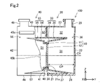
- FIG. FIG. 2 is a side view of a cell culture vessel shown in partial cross section.
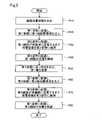
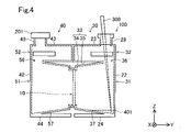
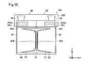
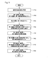
- 1 is a flow chart showing the steps of a liquid-air cell culture method. It is a schematic diagram of a cell culture vessel corresponding to the first step. It is a schematic diagram of a cell culture container corresponding to the second step. It is a schematic diagram of a cell culture vessel corresponding to the third step. It is a schematic diagram of a cell culture vessel corresponding to the fourth step. It is a figure which shows a cell culture container in the middle of rotation to a 3rd attitude
- FIG. 1 is an exploded perspective view of a cell culture vessel 100.
- FIG. FIG. 2 is a side view of the cell culture vessel 100 shown in partial cross section.
- the cross-section shown in FIG. 2 is a cross-sectional view taken along line II--II in FIG. 1 and 2 show an X-axis, a Y-axis, and a Z-axis, which are orthogonal to each other.
- the cell culture vessel 100 is typically used with the Z direction aligned with the vertical direction.
- the +Z direction may be referred to as the upward direction
- the ⁇ Z direction may be referred to as the downward direction.
- a cell culture vessel 100 includes a culture membrane 10 , a first vessel 20 and a second vessel 40 .
- the culture membrane 10 is sandwiched between the first vessel 20 and the second vessel 40 and used as an integrated unit.
- the cell culture vessel 100 is a vessel used for co-culturing cells on both sides of the culture membrane 10 .
- the first container 20 and the second container 40 have generally plane-symmetrical shapes.
- the first container 20 and the second container 40 are made of hard resin material, for example. Examples of hard resin materials include polystyrene, polycarbonate, and acrylic resins, and transparent resins are particularly preferred.
- the culture membrane 10 has a membrane support portion 11 and a cell culture membrane 12.
- the membrane support portion 11 is an annular frame.
- a circular cell culture membrane 12 is joined to the membrane supporting portion 11 .
- the cell culture membrane 12 is a membrane that serves as a scaffold for cell culture when performing cell culture.
- a porous membrane made of a synthetic polymer or a porous membrane made of a natural polymer having a large number of pores penetrating in the thickness direction of the membrane can be used.
- porous membranes include track etching membranes, nanofiber membranes, collagen vitrigel membranes, and porous polyurethane membranes.
- porous polyurethane film examples include a porous polyurethane film manufactured using a manufacturing method comprising a first step and a second step described below.
- the first step is to form a layer of uncured polyurethane raw material on a substrate.
- water vapor is supplied to the exposed surface of the polyurethane raw material layer formed on the substrate, which is separated from the substrate, to promote curing of the polyurethane raw material and form a plurality of irregularities in the polyurethane raw material layer. This is a step of forming a porous shape on the exposed surface.
- the first container 20 is a container having an approximately rectangular parallelepiped outer shape and an internal space.
- the first container 20 includes a first surface 21 , a second surface 22 , a third surface 23 , a fourth surface 24 , a fifth surface 25 , a sixth surface 26 , a holding portion 28 and an insertion opening 29 . and have The first surface 21 faces the second container 40 when integrated with the second container 40 , and has a holding portion 28 for holding the culture membrane 10 .
- the holding portion 28 has an annular shape and protrudes in the ⁇ Y direction orthogonal to the first surface 21 with the first surface 21 as a base end.
- a hole 21 a having a smaller diameter than the inner peripheral surface of the holding portion 28 is formed in the first surface 21 along the inner peripheral surface of the holding portion 28 . Therefore, the internal space of the first container 20 and the outside communicate with each other via the holding portion 28 .
- the culture membrane 10 is arranged inside the holding part 28 and outside the first surface 21 .
- the diameter of hole 21 a is smaller than the diameter of the inner peripheral surface of holding portion 28 . Therefore, the first surface 21 protrudes toward the central axis CX of the holding portion 28 in the radial direction with respect to the inner peripheral surface of the holding portion 28 . This restricts the movement of the culture membrane 10 toward the inner space of the first container 20 .
- the second surface 22 is a surface facing the first surface 21 in the Y direction.
- the direction from the first surface 21 to the second surface 22 is also called the first direction.
- the +Y direction is the first direction.
- the third surface 23 and the fourth surface 24 are surfaces that intersect the first surface 21 and the second surface 22 .
- two surfaces "intersect" means that the two surfaces intersect each other, the extension surface of one surface intersects the other surface, and the extension surface of the two surfaces intersects It means that it is either a state that intersects with
- the third surface 23 and the fourth surface 24 are surfaces facing each other in the Z direction.
- the fifth surface 25 and the sixth surface 26 are surfaces that intersect the first surface 21 , the second surface 22 , the third surface 23 and the fourth surface 24 .
- the fifth surface 25 and the sixth surface 26 are surfaces facing each other.
- An insertion opening 29 is provided on the third surface 23 .
- the insertion port 29 is used when an instrument such as a pipette is inserted into the first container 20 .
- the insertion port 29 has a cylindrical shape and protrudes in the +Z direction orthogonal to the third surface 23 with the third surface 23 as a base end.
- a hole is formed in the third surface 23 along the inner peripheral surface of the insertion port 29 . Therefore, the internal space of the first container 20 and the outside communicate with each other through the insertion port 29 .
- the thickness of the side wall of the insertion port 29 is not uniform, and the outer peripheral surface of the distal end protrudes outward in the radial direction with respect to the outer peripheral surface of the proximal end. This can prevent the first lid 201 from coming off when the first lid 201 described later is attached.
- the fifth surface 25 is formed with a first locking portion 25a, a second locking portion 25b, and a lid locking portion 25c.
- the first locking portion 25a and the second locking portion 25b have the same shape.
- the first locking portion 25a is formed above the center of the fifth surface 25 in the Z direction.
- the first locking portion 25a is formed on the fifth surface 25 at a position closer to the first surface 21 than the second surface 22 in the Y direction.
- the first locking portion 25 a has a plate shape elongated in the Y direction, and the base end portion is fixed to the fifth surface 45 .
- the tip of the first engaging portion 25a protrudes from the edge of the fifth surface 45 in the -Y direction.
- a claw for engaging with the first locking concave portion 45a of the second container 40 is formed at the tip of the first locking portion 25a. Specifically, the tip of the first locking portion 25a protrudes in the +X direction.
- the second locking portion 25b is arranged below the first locking portion 25a.
- the lid locking portion 25c is a convex portion for locking the second lid 202, which will be described later.
- the position of the lid locking portion 25c in the Z direction is approximately the same as that of the first locking portion 25a.
- the lid locking portion 25c is formed on the fifth surface 25 at a position closer to the second surface 22 than the first surface 21 in the Y direction.
- the lid locking portion 25 c has a rectangular shape elongated in the Y direction and protrudes from the fifth surface 25 .
- the sixth surface 46 also has a first locking portion 26a, a second locking portion 26b, and a lid locking portion 26c.
- the first locking portion 26a, the second locking portion 26b, and the lid locking portion 26c are respectively arranged with the YZ plane passing through the central axis CX as a plane of symmetry. , and the lid locking portion 25c.
- Each of the first locking portion 26a, the second locking portion 26b, and the lid locking portion 26c has the same shape as each of the first locking portion 25a, the second locking portion 25b, and the lid locking portion 25c. , the description is omitted.
- the first container 20 has a first cell 31, a second cell 32, a partition wall 33, and a communicating portion 36 in addition to the above configuration.
- the first cell 31 and the second cell 32 are spaces formed by dividing the internal space of the first container 20 by the partition wall 33 .
- the first cell 31 and the second cell 32 are adjacent to each other in the Z direction, which is the second direction perpendicular to the +Y direction, which is the first direction from the first surface 21 to the second surface 22 .
- the second cell 32 is partitioned by a third surface 23 facing the partition wall 33 in the second direction and a second surface 22 .
- the partition wall 33 extends in a direction from the first surface 21 toward the second surface 22 with the first surface 21 as a base end.
- the tip of the partition wall 33 is separated from the second surface 22 .
- the tip of the partition wall 33 is positioned between the second surface 22 and the central portion CP between the inner surface of the first surface 21 and the inner surface of the second surface 22 in the first direction.
- the partition wall 33 has a first cell surface 34 and a third cell surface 35 .
- the first cell 31 further has a second cell surface 37 .
- the second cell surface 37 is a surface facing the partition walls 33 .
- the first cell surface 34 and the second cell surface 37 are surfaces that partition the first cell 31 .
- the first cell surface 34 inclines so as to approach the third surface 23 as it approaches the second surface 22 . Accordingly, as will be described in detail later, when the first cell 31 is filled with liquid, air mixed in the liquid can be easily released.
- the communicating portion 36 is formed between the partition wall 33 and the second surface 22 and allows the first cell 31 and the second cell 32 to communicate with each other.
- the communicating portion 36 can also be said to be a gap between the tip of the partition wall 33 and the second surface 22 .
- the first cell 31 and the second cell 32 communicate with each other only through the communicating portion 36 .
- the communicating portion 36 is located between the central portion CP and the inner surface of the second surface 22 in the first direction, that is, the +Y direction for the first container 20 .
- the second cell surface 37 connects the first surface 21 and the fourth surface 24 .
- the second cell surface 37 is inclined away from the third surface 23 as it approaches the second surface 22 . That is, in the first posture in which the fourth surface 24 is set horizontally and serves as the bottom surface and the third surface 23 is the top surface, the second cell surface 37 is inclined downward as it approaches the second surface 22 . This makes it easier to suck out the liquid contained in the first cell 31, as will be described in detail later. Note that in the first posture, the first cell 31 is positioned below the second cell 32 . In the first posture, the pipette 300 is inserted through the insertion opening 29 and the first cell suspension 401 is injected, as will be described later.
- a gap is formed between the second cell surface 37 and the fourth surface 24 in this embodiment.
- the fourth surface 24 is notched in the X-direction central portion, and is formed at the +X-direction end and the ⁇ X-direction end of the first container 20 .
- the insertion port 29 is projected in the Z direction, which is the second direction orthogonal to the first direction from the first surface 21 to the second surface 22. , are formed at positions overlapping with the communicating portion 36 .
- an instrument such as the pipette 300 can be inserted from the insertion port 29 through the communicating portion 36 and generally along the second direction, thereby improving workability.
- the insertion port 29 in the first direction, that is, in the +Y direction for the first container 20, the insertion port 29 is positioned between the central portion CP between the inner surface of the first surface 21 and the inner surface of the second surface 22 when projected. , and the second surface 22 .
- the second container 40 like the first container 20, has a first surface 41, a second surface 42, a third surface 43, a fourth surface 44, and a fifth surface 45. , a sixth surface 46 , a holding portion 48 , and an insertion opening 49 .
- the holding portion 48 of the second container 40 differs in size from the holding portion 28 of the first container 20 .
- the outer diameter of the ring-shaped holding portion 48 is smaller than the inner diameter of the holding portion 28 .
- the holding portion 48 is covered with the holding portion 28 .
- the outer diameter of the holding portion 48 is substantially the same as the outer diameter of the culture membrane 10 .
- the first container 20 and the second container 40 are integrated with the culture membrane 10 sandwiched between the +Y direction end surface of the holding portion 48 and the first surface 21 of the first container 20 inside the holding portion 28. become. Thereby, the culture membrane 10 is held by the first container 20 and the second container 40 .
- the fifth face 45 is formed with a first engaging recess 45a, a second engaging recess 45b, and a lid engaging portion 45c. Since the lid locking portion 45c has the same configuration as the lid locking portion 25c of the first container 20, description thereof is omitted.
- the first locking recess 45a and the second locking recess 45b are formed so as to engage the first locking portion 25a and the second locking portion 25a of the first container, respectively. It is formed at a position corresponding to each tip of the portion 25b.
- the first locking recess 45 a and the second locking recess 45 b have a rectangular shape elongated in the Y direction and are recessed with respect to the fifth surface 25 .
- the tip of the first locking portion 25a is fitted into the first locking recess 45a, and the tip of the second locking portion 25b is the second locking portion. It fits into the stop recess 45b.
- the sixth surface 46 also has a first locking recess 46a and a second locking recess 46b corresponding to the first locking portion 26a and the second locking portion 26b of the first container 20. is formed. Then, when the first container 20 and the second container 40 are integrated, the respective tips of the first locking portion 26a and the second locking portion 26b are aligned with the first locking recess 46a and the second locking recess 46a. It fits in each of the locking recesses 46b.
- first locking portions 25a, 26a and the second locking portions 25b, 26b of the first container 20 and the first locking recesses 45a, 46a and the second locking recesses 45b of the second container 40 are connected to each other.
- 46b, the first container 20 and the second container 40 are integrated.
- the engagement between the first container 20 and the second container 40 is released.
- the first container 20 and the second container 40 can be handled together. Therefore, workability of work using the cell culture vessel 100 can be improved.
- the first surface 41, the second surface 42, the third surface 43, the fourth surface 44, the fifth surface 45, the sixth surface 46, and the insertion opening 49 are the first surface 21 and the second surface of the first container 20, respectively. Since the configuration is the same as that of the surface 22, the third surface 23, the fourth surface 24, the fifth surface 25, the sixth surface 26, and the insertion opening 29, the description thereof is omitted.
- the second container 40 has a first cell 51, a second cell 52, a partition wall 53, and a communicating portion 56 in addition to the above configuration.
- the partition wall 53 has a first cell surface 54 and a third cell surface 55 .
- the first cell 51 also has a second cell surface 57 .
- the first cell 51, the second cell 52, the partition wall 53, the communicating portion 56, and the second cell surface 57 are respectively the first cell 31, the second cell 32, the partition wall 33, and the first cell 31 of the first container 20.
- the configuration is the same as that of the communicating portion 36 and the second cell surface 37, so the description thereof is omitted.
- FIG. 3 is a flow chart showing the steps of the liquid-air cell culture method using the cell culture vessel 100.
- FIG. 4 to 10 are schematic diagrams of the cell culture vessel 100 for explaining each step shown in FIG. 4 to 10 show the X-axis, Y-axis, and Z-axis in the mode of use of the cell culture vessel 100.
- the Z direction indicates the vertical direction
- the XY plane indicates the horizontal plane.
- the +Z direction is also called up, and the ⁇ Z direction is also called down.
- the cell culture container 100 shown in FIG. 4 with the first lid 201 attached to the insertion port 49 of the second container 40 is prepared.
- the first lid 201 is made of, for example, a soft resin or an elastic material such as an elastomer.
- Soft resins include LDPE (Low Density Polyethylene) and PP (polypropylene).
- elastomers include silicone rubbers, polyurethanes, olefinic thermoplastic elastomers, and the like.
- the first lid 201 has a shape that covers the insertion opening 49 . When attached to the insertion port 49 , the first lid 201 is stretched and attached so as to cover the insertion port 49 . As a result, the end surface of the insertion port 49 in the Z direction is in close contact with the first lid 201, and the second container 40 is kept airtight.
- the cell culture vessel 100 is placed in a first posture (injection posture) in which the first cell 31 is positioned below the second cell 32.
- first posture injection posture
- the first cell suspension 401 is injected into the first container 20 through the insertion port 29 of the first container 20 .
- First cell suspension 401 contains first cells 402 and a first medium, which is a liquid for first cells 402 .
- the first cells 402 are seeded on the culture membrane 10 by injecting the first cell suspension 401 .
- a pipette 300 is used to inject a first cell suspension 401.
- the pipette 300 is inserted from the insertion port 29 through the communicating portion 36 until the tip reaches the vicinity of the fourth surface 24 .
- the culture membrane 10 is arranged on the first surface 21 intersecting the fourth surface, and movement of the pipette 300 toward the culture membrane 10 is restricted by the partition wall 33 . Therefore, contact between the pipette 300 and the culture membrane 10 can be suppressed. As a result, damage to the culture membrane 10 can be suppressed.
- the pipette 300 is used by an operator, but the injection work may be performed automatically using a device or the like without human intervention. According to the cell culture vessel 100 according to this embodiment, movement of the instrument toward the culture membrane 10 is restricted by the partition wall 33 .
- the insertion port 29 is fitted with the first lid 201 .
- the cell culture vessel 100 is arranged in a second posture (first fixing posture) in which the first container 20 is positioned above the second container 40 as shown in FIG.
- the cell culture vessel 100 is maintained in the second posture until the first cells 402 contained in the cell suspension 401 settle on the culture membrane 10 .
- the second posture is a posture in which the second surface 42 of the second container 40 is the bottom surface and the second surface 22 of the first container 20 is the top surface.
- the cell culture vessel 100 is rotated from the state of the first posture shown in FIG. 4 to the second posture shown in FIG. Since the insertion port 29 is fitted with the first lid 201 , the outflow of the first cell suspension 401 from the insertion port 29 is suppressed.
- FIG. 5 the state in which the first cell suspension 401 is contained only in the first cell 31 is depicted. 32 may also contain the first cell suspension 401 .
- the fixation of the first cells 402 to the culture membrane 10 is promoted. The period until the first cells 402 settle on the culture membrane 10 is, for example, about half a day to one day.
- the cell culture vessel 100 is placed in the first posture, the cell culture vessel 100 is maintained in the first posture, and the cultivation of the first cells 402 is continued.
- the cell culture vessel 100 is rotated from the second posture shown in FIG. 5 to the first posture shown in FIG. After that, the first lids 201, 201 attached to the respective insertion openings 29, 49 are removed, and the second lid 202 is attached.
- the second lid 202 is made of hard resin material. Examples of hard resin materials include polystyrene, polycarbonate, and acrylic resins, and transparent resins are particularly preferred.
- the second lid 202 is attached to the cell culture vessel 100 so as to cover the insertion openings 29 and 49 .
- the second lid 202 has a box shape that opens in the -Z direction.
- the inner peripheral surface of the second lid 202 is formed with four protrusions 202a that protrude inward. Each of the four projecting portions 202a is formed at a position corresponding to each of the lid locking portions 25c, 26c, 45c, and 46c of the cell culture vessel 100 when the second lid 202 is attached to the cell culture vessel 100. ing.
- each of the four projecting portions 202a abuts on each of the lid engaging portions 25c, 26c, 45c, 46c, and the bottom surface of the second lid 202 is separated from the insertion openings 29, 49.
- Attachment of the second lid 202 suppresses contamination during culture. Since the second lid 202 is attached to the cell culture vessel 100 while being separated from the end surfaces of the insertion ports 29 and 49, the internal space of the cell culture vessel 100 and the outside are kept in communication. Thereby, the gas in the internal space of the cell culture vessel 100 can be replaced.
- the cell culture vessel 100 is placed in an incubator adjusted to the target oxygen concentration and carbon dioxide concentration.
- the first medium is replaced as appropriate, and the first cells 402 are cultured until they become confluent.
- the culture period is, for example, several days.
- step P50 of FIG. 3 the second lid 202 is removed, the first culture medium is added to the first cell 31, and the first lid 201 is attached to the insertion port 29.
- the second cell suspension 403 is injected through the insertion port 49 of the second container 40 into the second container 40 of the cell culture container 100 arranged in the first posture.
- Second cell suspension 403 contains second cells 404 and a second medium, which is a liquid for second cells 404 .
- the pipette 300 is used to inject the second cell suspension 403 in the same manner as in the first step P20.
- the culture membrane 10 is arranged on the first surface 41 intersecting the fourth surface 44 , and movement of the pipette 300 toward the culture membrane 10 is restricted by the partition wall 53 . Therefore, contact between the pipette 300 and the culture membrane 10 can be suppressed.
- the insertion port 49 is fitted with the first lid 201 .
- the cell culture vessel 100 is maintained in the third posture until the contained second cells 404 settle on the culture membrane 10 .
- the third posture is a posture in which the second surface 22 of the first container 20 is the bottom surface and the second surface 42 of the second container 40 is the top surface.
- FIG. 8 is a diagram showing a state in which the cell culture vessel 100 is being rotated from the first posture to the third posture.
- a first cell suspension 401 is placed in the first container 20 with a space left above. The air in the space moves above the first container 20 as the cell culture container 100 rotates.
- the internal space of the first container 20 is not partitioned by the partition wall 33 , the air will move below the culture membrane 10 .
- the internal space of the first container 20 is partitioned by the partition wall 33 , so air is retained within the second cell 32 .
- residual air under the culture membrane 10 is suppressed, and the first cells 402 are kept in contact with the first culture medium.
- the membrane surface of the culture membrane 10 is arranged horizontally, thereby promoting the fixation of the second cells 404 to the culture membrane 10 .
- the period until the second cells 404 settle on the culture membrane 10 is, for example, about half a day to one day.
- the cell culture vessel 100 is placed in the first posture, and the cell culture vessel 100 is maintained in the first posture to continue culturing the second cells 404. .
- the cell culture vessel 100 is rotated from the state of the third posture shown in FIG. 9 to the first posture shown in FIG. After that, the first lids 201, 201 attached to the respective insertion openings 29, 49 are removed, and the second lid 202 is attached.
- the second medium is appropriately replaced, and the second cells 404 are cultured until they become confluent.
- the culture period is, for example, several days.
- the insertion openings 29, 49 are inserted into each of the two TEER electrodes.
- the cell culture vessel 100 is formed with an insertion port 29 and an insertion port 49 facing each other with the culture membrane 10 interposed therebetween. Therefore, by inserting each of the two TEER electrodes into the insertion port 29 and the insertion port 49, measurement can be easily performed. Note that the measurement of the transepithelial electrical resistance is not limited to the end of the culturing step.
- the measurement can be performed in a state in which the first medium is injected into the second container 40.
- FIG. 11 is a flow chart showing steps of a liquid-liquid cell culture method using the cell culture vessel 100 .
- the same steps as in FIG. 3 are denoted by the same reference numerals, and detailed description thereof will be omitted as appropriate.
- the first culture medium is injected into the second container 40 with the pipette 300 in step P25.
- the first cells 402 can be cultured while both surfaces of the cell culture membrane 12 are in contact with the first medium.
- a second step P30 and a third step P40 are performed, and the first cells 402 are cultured until they become confluent.
- the first medium is aspirated from the second container 40 using, for example, the pipette 300, and the second cell suspension 403 is injected.
- Process P65 is also called a fourth process. After that, the first lid 201 is attached to the insertion port 49 .
- the first culture medium since the second cell surface 57 is inclined, the first culture medium accumulates below the second cell surface 57 . Therefore, the first culture medium can be easily sucked out of the second container 40 .
- the suction of the first medium may be performed by an aspirator.
- movement of the instrument toward the culture membrane 10 is restricted by the partition wall 33 . Therefore, high positional accuracy is not required for the operation of the instrument to prevent damage to the culture membrane 10, and the operation can be performed automatically.
- a fifth step P70 and a sixth step P80 are performed to culture the second cells until they become confluent, and the main culture step ends.
- the first container 20 includes the partition walls 33 that partition the first cells 31 and the second cells 32
- the second container 40 includes the first cells 51 and the second cells 52. It has a partition wall 53 that partitions the
- the partition walls 33 and 53 reduce the possibility of the pipette 300 contacting the culture membrane 10 .
- the cell culture vessel 100 when the cell culture vessel 100 is projected in a second direction orthogonal to the first direction from the first surface 21 to the second surface 22, at least a part of the insertion port 29 is formed at a position overlapping the communicating portion 36. It is As a result, the pipette 300 can be inserted along the second direction from the insertion port 29 through the communicating portion 36, thereby improving workability.
- the partition wall 33 also has a first cell surface 34 that slopes toward the third surface 23 as it approaches the second surface 22 .
- the first cell 31 has a second cell surface 37 that slopes away from the third surface 23 as it approaches the second surface 22 .
- the cell culture vessel 100 has a fourth surface 24 that supports the second cell surface 37 so as to be inclined with respect to the horizontal direction in the orientation of the cell culture vessel 100 in which the fourth surface 24 is placed on a horizontal surface.
- the fourth surface 24 of the cell culture vessel 100 is placed on the horizontal surface, and the second cell surface 37 is inclined with respect to the horizontal surface, thereby improving the workability of operations such as sucking out liquid. can.
- the cell culture method that includes the first step P20 to the sixth step P80 and uses the cell culture vessel 100, it is possible to perform good co-cultivation in the cell culture vessel of the above configuration.
- both the first container 20 and the second container 40 are formed with the fourth surfaces 24 , 44 .
- either the fourth surface 24 or the fourth surface 44 may be formed on either one of the first container 20 and the second container 40 . Since the first container 20 and the second container 40 are used in an integrated manner, by having the fourth surface 24 on either one of the first container 20 and the second container 40, the second cell surface 37 , 57 can be maintained at an angle to the horizontal.
- the second cell surface 37 is inclined all the way to the second surface 22 .
- the second cell surface 37 may be configured to be inclined halfway to the second surface 22 . Even when a part is inclined, the liquid can be collected in the part, and the liquid can be easily sucked out.
- the tip of the partition wall 33 is positioned between the central portion CP and the second surface 22 .
- the tip of the partition wall 33 may be configured to be positioned between the central portion CP and the first surface 21 or in the central portion CP in the first direction.
- the partition wall 53 is also the same.
- the partition wall 33 is positioned on a line connecting the tip opening of the insertion port 29 and the culture membrane 10 (an arbitrary portion of the culture membrane 10). By doing so, when a rod-shaped instrument such as a pipette 300 is inserted into the cell culture vessel 100 through the insertion port 29, the partition wall 33 serves as a barrier to prevent the instrument from coming into contact with the culture membrane 10 more reliably. .
- the present disclosure is not limited to the above-described embodiments, and can be implemented in various configurations without departing from the scope of the present disclosure.
- the technical features of the embodiments corresponding to the technical features in each form described in the outline of the invention are used to solve some or all of the above problems, or Alternatively, replacements and combinations can be made as appropriate to achieve all. Also, if the technical features are not described as essential in this specification, they can be deleted as appropriate.
Landscapes
- Health & Medical Sciences (AREA)
- Wood Science & Technology (AREA)
- Organic Chemistry (AREA)
- Life Sciences & Earth Sciences (AREA)
- Engineering & Computer Science (AREA)
- Bioinformatics & Cheminformatics (AREA)
- Chemical & Material Sciences (AREA)
- Zoology (AREA)
- Biomedical Technology (AREA)
- Sustainable Development (AREA)
- Microbiology (AREA)
- Biotechnology (AREA)
- Biochemistry (AREA)
- General Engineering & Computer Science (AREA)
- General Health & Medical Sciences (AREA)
- Genetics & Genomics (AREA)
- Clinical Laboratory Science (AREA)
- Immunology (AREA)
- Apparatus Associated With Microorganisms And Enzymes (AREA)
- Micro-Organisms Or Cultivation Processes Thereof (AREA)
Abstract
第1容器と、第2容器と、第1容器と、第2容器との間に保持される培養膜と、を備え、第1容器と、第2容器とは、それぞれ、培養膜を保持する保持部を有する第1面と、第1面と対向する第2面と、第1面から第2面に向かう第1方向と直交する第2方向に隣り合う第1セルおよび第2セルと、第1セルと第2セルとを区画する隔壁であって、第1面から第2面へ向かって延びる隔壁と、隔壁と第2面との間に形成された第1セルと第2セルとを連通させる連通部と、隔壁と第2方向において対向し、第2面と共に第2セルを区画する第3面であって、挿入口が形成された第3面と、を備える、細胞培養容器。
Description
本開示は、細胞培養容器および細胞培養方法に関する。
従来、両面において細胞を培養する培養膜を備える細胞培養器具が知られている(例えば、特許文献1)。特許文献1の細胞培養器具は、内筒の一方の端部に培養膜が配置されており、内筒の他方の端部が開放されている。そして、例えばピペットなどの器具が内筒の内部に挿入される際には、他方の端部から、培養膜に向かって、器具が挿入される。
しかしながら、特許文献1に記載の細胞培養器具では、器具が培養膜に向かって内筒に挿入されるため、器具の先端が細胞膜と接触する可能性が高くなる。器具の先端が細胞膜に接触した場合、細胞膜が傷つくおそれが生じる。よって、従来の技術では、器具の先端が細胞膜に接触しないように慎重な操作が要求されるため、作業性が低下するおそれがある。
本開示は、以下の形態として実現することが可能である。
(1)本開示の一形態によれば、細胞培養容器が提供される。この細胞培養容器は、第1容器と、第2容器と、前記第1容器と、前記第2容器との間に保持される培養膜と、を備え、前記第1容器と、前記第2容器とは、それぞれ、前記培養膜を保持する保持部を有する第1面と、前記第1面と対向する第2面と、前記第1面から前記第2面に向かう第1方向と直交する第2方向に隣り合う第1セルおよび第2セルと、前記第1セルと前記第2セルとを区画する隔壁であって、前記第1面から前記第2面へ向かって延びる隔壁と、前記隔壁と前記第2面との間に形成された前記第1セルと前記第2セルとを連通させる連通部と、前記隔壁と前記第2方向において対向し、前記第2面と共に前記第2セルを区画する第3面であって、挿入口が形成された第3面と、を備える。この形態によれば、ピペットなどの器具が挿入口から挿入される際、ピペットの培養膜への接触の可能性は、隔壁によって低減される。これにより、ピペットが培養膜に接触しないようにピペットの操作を慎重に行う程度を低減できるため、作業性を向上させることができる。
(2)上記形態の細胞培養容器において、前記第2方向に前記細胞培養容器を投影した場合に、前記挿入口の少なくとも一部は、前記連通部と重なる位置に形成されていてもよい。この形態によれば、器具を挿入口から連通部を通るように、第2方向に沿って挿入することができるため、作業性を向上させることができる。
(3)上記形態の細胞培養容器において、前記隔壁は、さらに、第1セルを区画する第1セル面であって、前記第2面に近づくにつれ、前記第3面に近づくように傾斜する第1セル面を有していてもよい。この形態によれば、細胞培養容器が、第2セルに対して第1セルが下方に位置する第1姿勢に配置された場合、細胞培養容器に入れられた液体に混入した空気は、浮力により、傾斜している第1セル面に沿って、上方に移動する。よって、培養膜の下における空気の残留は抑制されるため、培養膜での培養を良好に行うことができる。
(4)上記形態の細胞培養容器において、前記第1セルは、さらに、前記隔壁と対向し、前記第1面から前記第2面に向かって延びる第2セル面であって、前記第2面に近づくにつれ、前記第3面から遠ざかるように傾斜する第2セル面を有していてもよい。この形態によれば、細胞培養容器が、第2セルに対して第1セルが下方に位置する第1姿勢に配置された場合、細胞培養容器に入れられた液体は、重力により傾斜している第2セル面に沿って、下方に移動する。細胞培養容器に入れられた液体は、第1セルの第2セル面の下方に溜まるため、液体を吸い出し易くすることができる。
(5)上記形態の細胞培養容器において、前記第1容器および前記第2容器の少なくとも何れか一方は、さらに、前記第2セル面と対向する第4面であって、前記第4面が水平面に設置された前記細胞培養容器の姿勢において、前記第2セル面が水平方向に対して傾斜するように支持する第4面を備えていてもよい。この形態によれば、細胞培養容器の第4面が水平面に設置されることにより、第2セル面は水平面に対して傾斜した状態となるため、液体の吸い出しなどの作業の作業性を向上させることができる。
(6)上記形態の細胞培養容器を用いた細胞培養方法であって、前記細胞培養容器を前記第2セルに対して前記第1セルが下方に位置する第1姿勢に配置し、前記第1容器の前記挿入口を介して前記第1容器に第1細胞懸濁液を注入する第1工程と、前記第1工程の後に、前記細胞培養容器を前記第1容器が前記第2容器の上方に位置する第2姿勢に配置し、前記第1細胞懸濁液に含まれる第1細胞が前記培養膜に定着するまで前記培養容器を前記第2姿勢に維持する第2工程と、前記第2工程の後に、前記細胞培養容器を前記第1姿勢となるように配置し、前記細胞培養容器を前記第1姿勢に維持して前記第1細胞の培養を継続するための第3工程と、前記第3工程の後に、前記第1姿勢に配置された前記細胞培養容器の前記第2容器に第2細胞懸濁液を前記第2容器の前記挿入口を介して注入する第4工程と、前記第4工程の後に、前記細胞培養容器を前記第2容器が前記第1容器の上方に位置する第3姿勢に配置し、前記第2細胞懸濁液に含まれる第2細胞が前記培養膜に定着するまで前記細胞培養容器を前記第3姿勢に維持する第5工程と、前記第5工程の後に、前記細胞培養容器を前記第1姿勢となるように配置し、前記細胞培養容器を前記第1姿勢に維持して前記第2細胞の培養を継続するための第6工程と、を備えていてもよい。この形態によれば、上記形態の細胞培養容器において、良好に共培養を行うことができる。
(2)上記形態の細胞培養容器において、前記第2方向に前記細胞培養容器を投影した場合に、前記挿入口の少なくとも一部は、前記連通部と重なる位置に形成されていてもよい。この形態によれば、器具を挿入口から連通部を通るように、第2方向に沿って挿入することができるため、作業性を向上させることができる。
(3)上記形態の細胞培養容器において、前記隔壁は、さらに、第1セルを区画する第1セル面であって、前記第2面に近づくにつれ、前記第3面に近づくように傾斜する第1セル面を有していてもよい。この形態によれば、細胞培養容器が、第2セルに対して第1セルが下方に位置する第1姿勢に配置された場合、細胞培養容器に入れられた液体に混入した空気は、浮力により、傾斜している第1セル面に沿って、上方に移動する。よって、培養膜の下における空気の残留は抑制されるため、培養膜での培養を良好に行うことができる。
(4)上記形態の細胞培養容器において、前記第1セルは、さらに、前記隔壁と対向し、前記第1面から前記第2面に向かって延びる第2セル面であって、前記第2面に近づくにつれ、前記第3面から遠ざかるように傾斜する第2セル面を有していてもよい。この形態によれば、細胞培養容器が、第2セルに対して第1セルが下方に位置する第1姿勢に配置された場合、細胞培養容器に入れられた液体は、重力により傾斜している第2セル面に沿って、下方に移動する。細胞培養容器に入れられた液体は、第1セルの第2セル面の下方に溜まるため、液体を吸い出し易くすることができる。
(5)上記形態の細胞培養容器において、前記第1容器および前記第2容器の少なくとも何れか一方は、さらに、前記第2セル面と対向する第4面であって、前記第4面が水平面に設置された前記細胞培養容器の姿勢において、前記第2セル面が水平方向に対して傾斜するように支持する第4面を備えていてもよい。この形態によれば、細胞培養容器の第4面が水平面に設置されることにより、第2セル面は水平面に対して傾斜した状態となるため、液体の吸い出しなどの作業の作業性を向上させることができる。
(6)上記形態の細胞培養容器を用いた細胞培養方法であって、前記細胞培養容器を前記第2セルに対して前記第1セルが下方に位置する第1姿勢に配置し、前記第1容器の前記挿入口を介して前記第1容器に第1細胞懸濁液を注入する第1工程と、前記第1工程の後に、前記細胞培養容器を前記第1容器が前記第2容器の上方に位置する第2姿勢に配置し、前記第1細胞懸濁液に含まれる第1細胞が前記培養膜に定着するまで前記培養容器を前記第2姿勢に維持する第2工程と、前記第2工程の後に、前記細胞培養容器を前記第1姿勢となるように配置し、前記細胞培養容器を前記第1姿勢に維持して前記第1細胞の培養を継続するための第3工程と、前記第3工程の後に、前記第1姿勢に配置された前記細胞培養容器の前記第2容器に第2細胞懸濁液を前記第2容器の前記挿入口を介して注入する第4工程と、前記第4工程の後に、前記細胞培養容器を前記第2容器が前記第1容器の上方に位置する第3姿勢に配置し、前記第2細胞懸濁液に含まれる第2細胞が前記培養膜に定着するまで前記細胞培養容器を前記第3姿勢に維持する第5工程と、前記第5工程の後に、前記細胞培養容器を前記第1姿勢となるように配置し、前記細胞培養容器を前記第1姿勢に維持して前記第2細胞の培養を継続するための第6工程と、を備えていてもよい。この形態によれば、上記形態の細胞培養容器において、良好に共培養を行うことができる。
A.実施形態:
A1.細胞培養容器の構成:
図1は、細胞培養容器100の分解斜視図である。図2は、一部断面にて示す細胞培養容器100の側面図である。図2に示す断面は、図1のII-II線を切断線とする断面図である。図1および図2では、互いに直交する、X軸と、Y軸と、Z軸とを示している。細胞培養容器100は、典型的には、Z方向が鉛直方向と沿うように配置されて使用される。以下では、+Z方向を上方向、-Z方向を下方向として説明する場合がある。細胞培養容器100は、培養膜10と、第1容器20と、第2容器40とを備える。細胞培養容器100が細胞培養に用いられる際には、第1容器20と第2容器40との間に培養膜10が挟まれた状態で、一体化されて用いられる。細胞培養容器100は、培養膜10の両面に細胞を培養する共培養のために用いられる容器である。第1容器20と第2容器40とは、概ね面対称となる形状を有している。第1容器20および第2容器40は、例えば、硬質樹脂材料で形成されている。硬質樹脂材料としては、ポリスチレンや、ポリカーボネート、アクリル樹脂等が挙げられ、特に透明な樹脂が好ましい。
A1.細胞培養容器の構成:
図1は、細胞培養容器100の分解斜視図である。図2は、一部断面にて示す細胞培養容器100の側面図である。図2に示す断面は、図1のII-II線を切断線とする断面図である。図1および図2では、互いに直交する、X軸と、Y軸と、Z軸とを示している。細胞培養容器100は、典型的には、Z方向が鉛直方向と沿うように配置されて使用される。以下では、+Z方向を上方向、-Z方向を下方向として説明する場合がある。細胞培養容器100は、培養膜10と、第1容器20と、第2容器40とを備える。細胞培養容器100が細胞培養に用いられる際には、第1容器20と第2容器40との間に培養膜10が挟まれた状態で、一体化されて用いられる。細胞培養容器100は、培養膜10の両面に細胞を培養する共培養のために用いられる容器である。第1容器20と第2容器40とは、概ね面対称となる形状を有している。第1容器20および第2容器40は、例えば、硬質樹脂材料で形成されている。硬質樹脂材料としては、ポリスチレンや、ポリカーボネート、アクリル樹脂等が挙げられ、特に透明な樹脂が好ましい。
図1に示すように、培養膜10は、膜支持部11と、細胞培養膜12とを有する。膜支持部11は、円環形状の枠である。そして、膜支持部11に円形の細胞培養膜12が接合されている。細胞培養膜12は、細胞培養を行う際に、細胞培養の足場となる膜である。細胞培養膜12として、膜の厚み方向に貫通する多数の細孔を有する、合成高分子製の多孔質膜や天然高分子製の多孔質膜を用いることができる。具体的には、多孔質膜として、トラックエッチング膜や、ナノファイバー膜や、コラーゲンビトリゲル膜や、多孔質ポリウレタン膜などが挙げられる。多孔質ポリウレタン膜としては、次に記載する、第1工程および第2工程を備える製造方法を用いて製造された多孔質ポリウレタン膜などが挙げられる。第1工程は、基板上に未硬化であるポリウレタン原料の層を形成する工程である。第2工程は、基板上に形成されたポリウレタン原料の層における基板から離間した露出面に対して水蒸気の供給を行なって、ポリウレタン原料の層において、ポリウレタン原料の硬化を進行させると共に複数の凹凸を露出面に有する多孔質形状を形成させる工程である。
第1容器20は、概ね直方体の外形形状を有し、内部空間を有する容器である。第1容器20は、第1面21と、第2面22と、第3面23と、第4面24と、第5面25と、第6面26と、保持部28と、挿入口29と、を有する。第1面21は、第2容器40と一体化される際に、第2容器40と対向する面であり、培養膜10を保持するための保持部28を有する。保持部28は、円環形状であり、第1面21を基端として、第1面21と直交する-Y方向に突設されている。そして、第1面21には、保持部28の内周面に沿って、保持部28の内周面の直径よりも直径の小さい孔21aが形成されている。したがって、保持部28を介して、第1容器20の内部空間と外部とが連通している。図2に示すように、第1容器20と第2容器40とが一体化された場合には、保持部28の内側、かつ、第1面21の外側に、培養膜10が配置される。孔21aの直径は、保持部28の内周面の直径よりも小さい。よって、保持部28の内周面に対して、第1面21は径方向において保持部28の中心軸CXに向かって突出している。これにより、培養膜10の第1容器20の内部空間側への移動が規制される。
図1に示すように、第2面22は、Y方向において、第1面21と対向する面である。第1面21から第2面22へ向かう方向を第1方向とも呼ぶ。本実施形態の第1容器20においては、+Y方向が第1方向である。第3面23および第4面24は、第1面21および第2面22と交差する面である。ここで、2つの面が「交差する」とは、2つの面が相互に交差する状態に加え、一方の面の延長面が他方の面に交差する状態と、2つの面の延長面が相互に交差する状態と、のいずれかの状態であることを意味する。第3面23と、第4面24とは、Z方向において互いに対向する面である。第5面25および第6面26は、第1面21と、第2面22と、第3面23と、第4面24と交差する面である。第5面25と、第6面26とは、互いに対向する面である。
第3面23には、挿入口29が設けられている。挿入口29は、ピペットなどの器具が、第1容器20に挿入される際に用いられる。挿入口29は、円筒形状を有し、第3面23を基端として、第3面23と直交する+Z方向に突設されている。そして、第3面23には、挿入口29の内周面に沿って孔が形成されている。よって、挿入口29を介して、第1容器20の内部空間と外部とが連通している。挿入口29の側壁の厚さは均一ではなく、先端部の外周面が、基端部の外周面に対して、径方向において、外側に突出している。これにより、後述する第1蓋201が取り付けられた場合における、第1蓋201の脱落を抑制することができる。
第5面25には、第1係止部25aと、第2係止部25bと、蓋係止部25cとが形成されている。第1係止部25aと、第2係止部25bとは、同様の形状を有している。第1係止部25aは、Z方向において、第5面25の中央よりも上側に形成されている。また、第1係止部25aは、Y方向において、第2面22よりも第1面21に近い位置の第5面25に形成されている。第1係止部25aは、Y方向に長い板形状を有しており、基端部は第5面45に固定されている。そして、第1係止部25aの先端は、第5面45の-Y方向の端辺から突出している。第1係止部25aの先端には、第2容器40の第1係止凹部45aと係合するための爪が形成されている。具体的には、第1係止部25aの先端は、+X方向に向かって突出している。第2係止部25bは、第1係止部25aよりも下方に配置されている。蓋係止部25cは、後述する第2蓋202を係止するための凸部である。蓋係止部25cのZ方向における位置は、第1係止部25aと同程度である。また、蓋係止部25cは、Y方向において、第1面21よりも第2面22に近い位置の第5面25に形成されている。蓋係止部25cは、Y方向に長い矩形形状を有し、第5面25に突設されている。第5面25と同様に、第6面46にも、第1係止部26aと、第2係止部26bと、蓋係止部26cとが形成されている。第1係止部26a、第2係止部26b、および蓋係止部26cは、中心軸CXを通るYZ平面を対称面として、それぞれ、第1係止部25a、第2係止部25b、および蓋係止部25cと面対称となる位置に形成されている。第1係止部26a、第2係止部26b、および蓋係止部26cのそれぞれは、第1係止部25a、第2係止部25b、および蓋係止部25cのそれぞれと同様の形状を有するため、説明を省略する。
図2に示すように、第1容器20は、上記構成の他に、第1セル31と、第2セル32と、隔壁33と、連通部36とを有する。第1セル31と第2セル32とは、第1容器20の内部空間が隔壁33により区画されて形成された空間である。第1セル31および第2セル32は、第1面21から第2面22に向かう第1方向である+Y方向と直交する第2方向であるZ方向に隣り合う。第2セル32は、隔壁33と第2方向において対向する第3面23と、第2面22とにより区画されている。隔壁33は、第1面21を基端として、第1面21から第2面22へ向かう方向に延びる。そして、隔壁33の先端は、第2面22と離れている。本実施形態において、隔壁33の先端は、第1方向について、第1面21の内面と第2面22の内面との中央部CPと、第2面22との間に位置する。
隔壁33は、第1セル面34と第3セル面35とを有する。第1セル31は、さらに第2セル面37を有する。第2セル面37は、隔壁33と対向する面である。第1セル面34および第2セル面37は、第1セル31を区画する面である。第1セル面34は、第2面22に近づくにつれ、第3面23に近づくように傾斜する。これにより、後に詳述するように、第1セル31に液体が入れられた場合、液体に混入した空気を抜け易くすることができる。
連通部36は、隔壁33と第2面22との間に形成されており、第1セル31と第2セル32とを連通させる。つまり、連通部36は、隔壁33の先端と第2面22との隙間であるとも言える。第1セル31と第2セル32とは、連通部36のみによって連通している。本実施形態では、連通部36は、第1方向、すなわち第1容器20については+Y方向について、中央部CPと第2面22の内面との間に位置する。
第2セル面37は、第1面21と、第4面24とを連結する。第2セル面37は、第2面22に近づくにつれ、第3面23から遠ざかるように傾斜する。つまり、第4面24が水平面に設置され底面となり、第3面23が上面となる第1姿勢において、第2セル面37は、第2面22に近づくにつれ下方に位置するように傾斜する。これにより、後に詳述するように、第1セル31に入れられた液体を吸い出し易くすることができる。なお、第1姿勢では、第2セル32に対して第1セル31が下方に位置する。第1姿勢では、後述するように、挿入口29からピペット300が挿入されて第1細胞懸濁液401が注入される。
本実施形態では、第2セル面37と第4面24との間には、隙間が形成されている。図1に示すように、第4面24は、X方向の中央部分が切り欠かれており、第1容器20の+X方向の端部と、-X方向の端部とに形成されている。第4面24が形成されていることにより、細胞培養容器100の第1姿勢では、第1セル面34および第2セル面37が水平面に対して傾斜した状態を容易に維持することができる。
図2に示すように、挿入口29の少なくとも一部は、第1面21から第2面22に向かう第1方向と直交する第2方向であるZ方向に細胞培養容器100を投影した場合に、連通部36と重なる位置に形成されている。これにより、ピペット300などの器具を挿入口29から連通部36を通るように、概ね第2方向に沿うように挿入することができるため、作業性を向上させることができる。本実施形態では、第1方向、すなわち、第1容器20については+Y方向において、挿入口29は、投影した場合に、第1面21の内面と第2面22の内面との中央部CPと、第2面22との間に位置する。
図1に示すように、第2容器40は、第1容器20と同様に、第1面41と、第2面42と、第3面43と、第4面44と、第5面45と、第6面46と、保持部48と、挿入口49と、を有する。第2容器40の保持部48は、第1容器20の保持部28と、大きさが異なる。具体的には、円環形状である保持部48の外径は、保持部28の内径よりも小さい。そして、図2に示すように、第1容器20と第2容器40とが一体化された際、保持部48は保持部28により覆われる。また、保持部48の外径は、培養膜10の外径と略同一である。保持部48の+Y方向端面と、第1容器20の保持部28より内側の第1面21との間に培養膜10が挟まれた状態で、第1容器20と第2容器40とが一体化される。これにより、培養膜10は、第1容器20と第2容器40とにより保持される。
図1に示すように、第5面45には、第1係止凹部45aと、第2係止凹部45bと、蓋係止部45cとが形成されている。蓋係止部45cは、第1容器20に係る蓋係止部25cと同様の構成であるため、説明を省略する。第1係止凹部45aおよび第2係止凹部45bのそれぞれは、第1容器20と第2容器40とが一体化された場合に、第1容器の第1係止部25aおよび第2係止部25bのそれぞれの先端に対応する位置に形成されている。第1係止凹部45aおよび第2係止凹部45bは、Y方向に長い矩形形状を有し、第5面25に対して凹んでいる。第1容器20と、第2容器40とが一体化される際には、第1係止部25aの先端が第1係止凹部45aに嵌り、第2係止部25bの先端が第2係止凹部45bに嵌る。第6面46にも、第5面25と同様に、第1容器20の第1係止部26aおよび第2係止部26bに対応する、第1係止凹部46aおよび第2係止凹部46bが形成されている。そして、第1容器20と、第2容器40とが一体化される際には、第1係止部26aおよび第2係止部26bのそれぞれの先端が、第1係止凹部46aおよび第2係止凹部46bのそれぞれに嵌る。このように、第1容器20の第1係止部25a,26a、第2係止部25b,26bのそれぞれと、第2容器40の第1係止凹部45a,46a、第2係止凹部45b,46bのそれぞれとが係合されることにより、第1容器20と第2容器40とが一体化される。例えば、培養膜10を交換する際は、第1容器20と第2容器40との係合を解き、培養を行う場合には、第1容器20と第2容器40とを係合させ、第1容器20と第2容器40とを一体に扱うことができる。よって、細胞培養容器100を用いた作業の作業性を向上させることができる。
第1面41、第2面42、第3面43、第4面44、第5面45、第6面46、および挿入口49は、それぞれ、第1容器20の第1面21、第2面22、第3面23、第4面24、第5面25、第6面26、および挿入口29と同様の構成であるため、説明を省略する。図2に示すように、第2容器40は、上記構成の他に、第1セル51と、第2セル52と、隔壁53と、連通部56とを有する。隔壁53は、第1セル面54および第3セル面55を有する。第1セル51は、さらに、第2セル面57を有する。第1セル51と、第2セル52と、隔壁53と、連通部56、第2セル面57は、それぞれ、第1容器20の第1セル31と、第2セル32と、隔壁33と、連通部36、および第2セル面37と同様の構成であるため、説明を省略する。
A2.細胞培養容器を用いた液-気細胞培養方法:
細胞培養容器100を用いた液-気細胞培養方法について説明する。図3は、細胞培養容器100を用いた細胞の液-気細胞培養方法の工程を示すフローチャートである。図4~図10は、図3に示す各工程を説明するための細胞培養容器100の模式図である。図4~図10には、細胞培養容器100の使用態様における、X軸と、Y軸と、Z軸とが示されている。Z方向は、鉛直方向を示し、XY平面は、水平面を示す。+Z方向を上、-Z方向を下とも呼ぶ。
細胞培養容器100を用いた液-気細胞培養方法について説明する。図3は、細胞培養容器100を用いた細胞の液-気細胞培養方法の工程を示すフローチャートである。図4~図10は、図3に示す各工程を説明するための細胞培養容器100の模式図である。図4~図10には、細胞培養容器100の使用態様における、X軸と、Y軸と、Z軸とが示されている。Z方向は、鉛直方向を示し、XY平面は、水平面を示す。+Z方向を上、-Z方向を下とも呼ぶ。
まず図3の工程P10にて、図4に示す、第2容器40の挿入口49に第1蓋201が装着されている細胞培養容器100が用意される。第1蓋201は、例えば、軟質樹脂や、エラストマーなどの弾性を有する材料で作製されている。軟質樹脂としては、LDPE(Low Density Polyethylene)、PP(polypropylene)を挙げることができる。エラストマーとしては、シリコーンゴム、ポリウレタン、オレフィン系熱可塑性エラストマー等を挙げることができる。第1蓋201は、挿入口49を覆う形状を有する。挿入口49に取り付けられる際には、第1蓋201が引き延ばされて、挿入口49を覆うように装着される。これにより、挿入口49のZ方向の端面は、第1蓋201と密着し、第2容器40は、気密に保たれる。
図3の第1工程P20では、細胞培養容器100は第2セル32に対して第1セル31が下方に位置する第1姿勢(注入姿勢)に配置される。この第1姿勢にて、第1容器20の挿入口29を介して第1容器20に第1細胞懸濁液401が注入される。第1細胞懸濁液401には、第1細胞402と、第1細胞402用の液体である第1培地とが含まれている。第1細胞懸濁液401が注入されることにより、第1細胞402が培養膜10に播種される。図4に示すように、第1工程P20では、ピペット300を用いて、第1細胞懸濁液401が注入される。この際、ピペット300は、挿入口29から連通部36を通り、先端が第4面24近傍まで挿入される。培養膜10は、第4面と交差する第1面21に配置されており、また、ピペット300の培養膜10に向かう移動は、隔壁33により制限される。よって、ピペット300と培養膜10との接触を抑制することができる。これにより、培養膜10の破損を抑制することができる。なお、本実施形態では、作業者によりピペット300を用いて作業されるが、人の手を介さず、装置などを用いて自動で注入作業が行われてもよい。本実施形態に係る細胞培養容器100によれば、器具の培養膜10に向かう移動は、隔壁33により制限される。このため、培養膜10を損傷させないための器具の操作に係る高い位置精度は要求されず、自動で行うことができる。これにより、作業時間を短縮することができる。第1細胞懸濁液401が注入された後、挿入口29に第1蓋201が装着される。
図3の第2工程P30では、細胞培養容器100は、図5に示すように第1容器20が第2容器40の上方に位置する第2姿勢(第1定着姿勢)に配置され、第1細胞懸濁液401に含まれる第1細胞402が培養膜10に定着するまで細胞培養容器100は第2姿勢に維持される。第2姿勢は、第2容器40の第2面42が底面となり、第1容器20の第2面22が上面となる姿勢である。
第2工程P30では、細胞培養容器100は、図4に示す第1姿勢の状態から図5に示す第2姿勢となるように回転される。挿入口29には、第1蓋201が装着されているため、挿入口29からの第1細胞懸濁液401の流出は抑制される。なお、図5では、第1細胞懸濁液401が第1セル31のみに入っている状態が描かれているが、第1細胞懸濁液401の量が多い場合などには、第2セル32にも第1細胞懸濁液401が入る場合がある。培養膜10の膜面が水平方向に配置されることにより、第1細胞402の培養膜10への定着が促される。第1細胞402が培養膜10に定着するまでの期間は、例えば、半日から1日で程度である。
図3の第3工程P40では、細胞培養容器100は第1姿勢となるように配置され、細胞培養容器100は第1姿勢に維持され、第1細胞402の培養が継続される。第3工程P40では、細胞培養容器100は、図5に示す第2姿勢の状態から、図6に示す第1姿勢となるように回転される。その後、挿入口29,49の各々に装着されていた第1蓋201,201が取り外され、第2蓋202が装着される。
ここで、第2蓋202について説明する。第2蓋202は、硬質樹脂材料で作製されている。硬質樹脂材料としては、ポリスチレンや、ポリカーボネート、アクリル樹脂等が挙げられ、特に透明な樹脂が好ましい。第2蓋202は、挿入口29,49を覆うように細胞培養容器100に装着される。第2蓋202は、-Z方向に向かって開放された箱形状を有する。第2蓋202の内周面には、内側に向かって突出する4つの突出部202aが形成されている。4つの突出部202aの各々は、第2蓋202が細胞培養容器100に装着された場合に、細胞培養容器100の蓋係止部25c,26c,45c,46cの各々と対応する位置に形成されている。これにより、4つの突出部202aの各々は、蓋係止部25c,26c,45c,46cの各々と当接し、第2蓋202の底面が挿入口29,49と離隔した状態で配置される。第2蓋202が装着されることにより、培養中のコンタミネーションが抑制される。第2蓋202は、挿入口29,49の端面と離隔した状態で細胞培養容器100に装着されるため、細胞培養容器100の内部空間と、外部とは連通した状態が維持される。これにより、細胞培養容器100の内部空間の気体の置換を行うことができる。培養中は、細胞培養容器100は、目標の酸素濃度や二酸化炭素濃度に調整されたインキュベータ内に配置される。適宜、第1培地の交換が行われ、第1細胞402がコンフルエントになるまで培養される。培養期間は、例えば、数日程度である。
図3の工程P50では、第2蓋202が取り外され、第1セル31に第1培地が加えられ、挿入口29に第1蓋201が装着される。第4工程P60では、第1姿勢に配置された細胞培養容器100の第2容器40に第2細胞懸濁液403が第2容器40の挿入口49を介して注入される。第2細胞懸濁液403には、第2細胞404と、第2細胞404用の液体である第2培地とが含まれている。第2細胞懸濁液403が注入されることにより、第2細胞懸濁液403に含まれる第2細胞404が培養膜10に播種される。図7に示すように、第4工程P60では、第1工程P20と同様にピペット300を用いて第2細胞懸濁液403が注入される。培養膜10は、第4面44と交差する第1面41に配置されており、また、ピペット300の培養膜10に向かう移動は、隔壁53により制限される。よって、ピペット300と培養膜10との接触を抑制することができる。第2細胞懸濁液403が注入された後、挿入口49に第1蓋201が装着される。
図3の第5工程P70にて、細胞培養容器100は第2容器40が第1容器20の上方に位置する第3姿勢(第2定着姿勢)に配置され、第2細胞懸濁液403に含まれる第2細胞404が培養膜10に定着するまで、細胞培養容器100は第3姿勢に維持される。第3姿勢は、第1容器20の第2面22が底面となり、第2容器40の第2面42が上面となる姿勢である。
図8は、細胞培養容器100が、第1姿勢から第3姿勢になるように回転される途中の状態を示す図である。第1容器20には、上部に空間を残した状態で、第1細胞懸濁液401が入れられている。空間の空気は、細胞培養容器100の回転に応じて、第1容器20の上方へ移動する。ここで、第1容器20の内部空間が、隔壁33により区画されていない場合には、空気は、培養膜10の下方へ移動してしまう。この点、本実施形態では、第1容器20の内部空間は、隔壁33により区画されているため、空気は、第2セル32内に留められる。これにより、培養膜10の下方における空気の残留が抑制され、第1細胞402は第1培地と接触された状態が確保される。さらに、回転の際に、第1細胞懸濁液401に泡が生じた場合にも、泡は第2セル32に留められる。よって、培養を良好に行うことができる。図9に示す第3姿勢では、培養膜10の膜面が水平方向に配置されることにより、第2細胞404の培養膜10への定着が促される。第2細胞404が培養膜10に定着するまでの期間は、例えば、半日から1日で程度である。
図3の第6工程P80では、細胞培養容器100は第1姿勢となるように配置され、細胞培養容器100は、第1姿勢に維持されることで、第2細胞404の培養が継続される。第6工程P80では、細胞培養容器100は、図9に示す第3姿勢の状態から図10に示す第1姿勢となるように回転される。その後、挿入口29,49の各々に装着されていた第1蓋201,201が取り外され、第2蓋202が装着される。第3工程P40と同様に、適宜、第2培地の交換が行われ、第2細胞404がコンフルエントになるまで培養される。培養期間は、例えば、数日程度である。第2細胞404の培養が終了すると、本培養工程は、終了する。
培養終了後、第1細胞402および第2細胞404が培養された培養膜10について、バリヤ性を評価するために、経上皮電気抵抗(TEER)が測定される場合には、挿入口29,49の各々に2本のTEER電極の各々が挿入される。細胞培養容器100は、培養膜10を挟んで対向するように、挿入口29と挿入口49とが形成されている。よって、挿入口29と挿入口49とに、2本のTEER電極の各々を挿入することで、測定を容易に行うことができる。なお、経上皮電気抵抗が測定されるのは、培養工程の終了後に限られない。例えば、培養膜10に第1細胞402が培養された後、第2容器40に第1培地が注入された状態で、測定することもできる。すなわち、培養膜10の片面のみに細胞が培養された状態でも、TEERを測定可能にすることができる。
A3.細胞培養容器を用いた液-液細胞培養方法:
細胞培養容器100を用いた液-液細胞培養方法について説明する。図11は、細胞培養容器100を用いた細胞の液-液細胞培養方法の工程を示すフローチャートである。図3と同じ工程については、同じ符号を付し、詳細な説明は、適宜省略する。
細胞培養容器100を用いた液-液細胞培養方法について説明する。図11は、細胞培養容器100を用いた細胞の液-液細胞培養方法の工程を示すフローチャートである。図3と同じ工程については、同じ符号を付し、詳細な説明は、適宜省略する。
第1工程P20にて第1容器20に第1細胞懸濁液401が注入された後、工程P25では、第2容器40に第1培地がピペット300にて注入される。これにより、細胞培養膜12の両面が、第1培地に接触した状態で、第1細胞402の培養を行うことができる。その後、第2工程P30と、第3工程P40とが行われ、第1細胞402がコンフルエントになるまで培養される。工程P65では、第2細胞404の培養を行うため、第2容器40から第1培地が例えばピペット300を用いて吸い出され、第2細胞懸濁液403が注入される。工程P65を第4工程とも呼ぶ。その後、挿入口49に第1蓋201が装着される。ここで、第2セル面57は、傾斜しているため、第1培地は、第2セル面57の下方に溜まる。よって、第2容器40から第1培地を容易に吸い出すことができる。なお、第1培地の吸い出しは、アスピレーターにより行われてもよい。本実施形態に係る細胞培養容器100によれば、器具の培養膜10に向かう移動は、隔壁33により制限される。このため、培養膜10を損傷させないための器具の操作に係る高い位置精度は要求されず、自動で行うことができる。その後、第5工程P70と、第6工程P80とが行われることにより、第2細胞がコンフルエントになるまで培養され、本培養工程は終了する。
以上、説明した実施形態によれば、第1容器20は、第1セル31と第2セル32とを区画する隔壁33を備え、第2容器40は、第1セル51と第2セル52とを区画する隔壁53とを有する。これにより、ピペット300などが挿入口29,49から挿入される際、ピペット300の培養膜10への接触の可能性は、隔壁33,53によって低減される。これにより、ピペット300が培養膜10に接触しないように、ピペット300の操作を慎重に行う程度を低減できるため、作業性を向上させることができる。また、第1面21から第2面22に向かう第1方向と直交する第2方向に細胞培養容器100を投影した場合に、挿入口29の少なくとも一部は、連通部36と重なる位置に形成されている。これにより、ピペット300を挿入口29から連通部36を通るように、第2方向に沿って挿入することができるため、作業性を向上させることができる。また、隔壁33は、第2面22に近づくにつれ、第3面23に近づくように傾斜する第1セル面34を有している。これにより、細胞培養容器100が第1姿勢に配置された場合、培養膜10の下における空気の残留は抑制されるため、培養膜10での培養を良好に行うことができる。また、第1セル31は、第2面22に近づくにつれ、第3面23から遠ざかるように傾斜する第2セル面37を有する。これにより、細胞培養容器100に入れられた液体は、第1セル31の第2セル面37の下方に溜まるため、液体を吸い出し易くすることができる。また、細胞培養容器100は、第4面24が水平面に設置された細胞培養容器100の姿勢において、第2セル面37が水平方向に対して傾斜するように支持する第4面24を備える。これにより、細胞培養容器100の第4面24が水平面に設置されることにより、第2セル面37は水平面に対して傾斜されるため、液体の吸い出しなどの作業の作業性を向上させることができる。また、上記、第1工程P20から第6工程P80を備え、細胞培養容器100を用いる細胞培養方法を用いることにより、上記形態の細胞培養容器において、良好に共培養を行うことができる。
B.他の実施形態:
(B1)上記実施形態では、第1容器20と第2容器40との両方に第4面24,44が形成されている。これに対して、第1容器20と第2容器40とのいずれか一方に第4面24および第4面44のいずれかが形成されている構成としてもよい。第1容器20と第2容器40とは、一体化されて使用されるため、第1容器20と第2容器40とのいずれか一方に第4面24を有することにより、第2セル面37,57を水平面に対して傾斜した状態に維持することができる。
(B1)上記実施形態では、第1容器20と第2容器40との両方に第4面24,44が形成されている。これに対して、第1容器20と第2容器40とのいずれか一方に第4面24および第4面44のいずれかが形成されている構成としてもよい。第1容器20と第2容器40とは、一体化されて使用されるため、第1容器20と第2容器40とのいずれか一方に第4面24を有することにより、第2セル面37,57を水平面に対して傾斜した状態に維持することができる。
(B2)上記実施形態では、第2セル面37は、第2面22に至るまで傾斜している。これに対して、第2セル面37は、第2面22に至る途中まで傾斜している構成としてもよい。一部分が傾斜している場合にも、液体を一部分に集めることができ、液体を吸い出し易くすることができる。
(B3)上記実施形態では、隔壁33の先端は、中央部CPと、第2面22との間に位置する。これに対して、隔壁33の先端は、第1方向について、中央部CPと第1面21との間、または、中央部CPに位置する構成としてもよい。隔壁33の先端位置に拘わらず、隔壁33があることによって、器具が挿入口29から挿入される際、器具の培養膜10への接触の可能性を低減させることができる。隔壁53についても同様である。ただし、上記実施形態において、挿入口29と隔壁33と培養膜10との位置は以下の位置関係を有することが好ましい。すなわち、挿入口29の先端開口と培養膜10(培養膜10の任意の部分)とを繋ぐ線分上に、隔壁33が位置していることが好ましい。こうすることで、ピペット300などの棒状の器具を挿入口29から細胞培養容器100内部に挿入した場合に、隔壁33が障壁となって器具が培養膜10に接触することをより確実に防止できる。
本開示は、上述の実施形態に限られるものではなく、その趣旨を逸脱しない範囲において種々の構成で実現することができる。例えば、発明の概要の欄に記載した各形態中の技術的特徴に対応する実施形態の技術的特徴は、上述の課題の一部又は全部を解決するために、あるいは、上述の効果の一部又は全部を達成するために、適宜、差し替えや、組み合わせを行うことが可能である。また、その技術的特徴が本明細書中に必須なものとして説明されていなければ、適宜、削除することが可能である。
10…培養膜、11…膜支持部、12…細胞培養膜、20…第1容器、21,41…第1面、21a…孔、22,42…第2面、23,43…第3面、24,44…第4面、25,45…第5面、25a…第1係止部、25b…第2係止部、25c,26c,45c,46c…蓋係止部、26,46…第6面、26a…第1係止部、26b…第2係止部、28,48…保持部、29,49…挿入口、31,51…第1セル、32,52…第2セル、33,53…隔壁、34,54…第1セル面、35,55…第3セル面、36,56…連通部、37,57…第2セル面、40…第2容器、45a…第1係止凹部、45b…第2係止凹部、46a…第1係止凹部、46b…第2係止凹部、100…細胞培養容器、201…第1蓋、202…第2蓋、202a…突出部、300…ピペット、401…第1細胞懸濁液、402…第1細胞、403…第2細胞懸濁液、404…第2細胞、CP…中央部、CX…中心軸、P10,P25,P50,P65…工程、P20…第1工程、P30…第2工程、P40…第3工程、P60…第4工程、P70…第5工程、P80…第6工程
Claims (6)
- 細胞培養容器であって、
第1容器と、
第2容器と、
前記第1容器と、前記第2容器との間に保持される培養膜と、を備え、
前記第1容器と、前記第2容器とは、それぞれ、
前記培養膜を保持する保持部を有する第1面と、
前記第1面と対向する第2面と、
前記第1面から前記第2面に向かう第1方向と直交する第2方向に隣り合う第1セルおよび第2セルと、
前記第1セルと前記第2セルとを区画する隔壁であって、前記第1面から前記第2面へ向かって延びる隔壁と、
前記隔壁と前記第2面との間に形成された前記第1セルと前記第2セルとを連通させる連通部と、
前記隔壁と前記第2方向において対向し、前記第2面と共に前記第2セルを区画する第3面であって、挿入口が形成された第3面と、を備える、細胞培養容器。 - 請求項1に記載の細胞培養容器であって、
前記第2方向に前記細胞培養容器を投影した場合に、前記挿入口の少なくとも一部は、前記連通部と重なる位置に形成されている、細胞培養容器。 - 請求項1または2に記載の細胞培養容器であって、
前記隔壁は、さらに、
前記第1セルを区画する第1セル面であって、前記第2面に近づくにつれ、前記第3面に近づくように傾斜する第1セル面を有する、細胞培養容器。 - 請求項1から3の何れか一項に記載の細胞培養容器であって、
前記第1セルは、さらに、
前記隔壁と対向し、前記第1面から前記第2面に向かって延びる第2セル面であって、前記第2面に近づくにつれ、前記第3面から遠ざかるように傾斜する第2セル面を有する、細胞培養容器。 - 請求項4に記載の細胞培養容器であって、
前記第1容器および前記第2容器の少なくとも何れか一方は、さらに、
前記第2セル面と対向する第4面であって、前記第4面が水平面に設置された前記細胞培養容器の姿勢において、前記第2セル面が水平方向に対して傾斜するように支持する第4面を備える、細胞培養容器。 - 請求項1から5の何れか一項に記載の細胞培養容器を用いた細胞培養方法であって、
前記細胞培養容器を前記第2セルに対して前記第1セルが下方に位置する第1姿勢に配置し、前記第1容器の前記挿入口を介して前記第1容器に第1細胞懸濁液を注入する第1工程と、
前記第1工程の後に、前記細胞培養容器を前記第1容器が前記第2容器の上方に位置する第2姿勢に配置し、前記第1細胞懸濁液に含まれる第1細胞が前記培養膜に定着するまで前記細胞培養容器を前記第2姿勢に維持する第2工程と、
前記第2工程の後に、前記細胞培養容器を前記第1姿勢となるように配置し、前記細胞培養容器を前記第1姿勢に維持して前記第1細胞の培養を継続するための第3工程と、
前記第3工程の後に、前記第1姿勢に配置された前記細胞培養容器の前記第2容器に第2細胞懸濁液を前記第2容器の前記挿入口を介して注入する第4工程と、
前記第4工程の後に、前記細胞培養容器を前記第2容器が前記第1容器の上方に位置する第3姿勢に配置し、前記第2細胞懸濁液に含まれる第2細胞が前記培養膜に定着するまで前記細胞培養容器を前記第3姿勢に維持する第5工程と、
前記第5工程の後に、前記細胞培養容器を前記第1姿勢となるように配置し、前記細胞培養容器を前記第1姿勢に維持して前記第2細胞の培養を継続するための第6工程と、を備える、細胞培養方法。
Priority Applications (2)
| Application Number | Priority Date | Filing Date | Title |
|---|---|---|---|
| DE112022000594.7T DE112022000594T5 (de) | 2021-03-25 | 2022-02-22 | Zellkulturbehälter und zellkulturverfahren |
| US18/547,168 US20240124818A1 (en) | 2021-03-25 | 2022-02-22 | Cell culture container and cell culture method |
Applications Claiming Priority (2)
| Application Number | Priority Date | Filing Date | Title |
|---|---|---|---|
| JP2021-050919 | 2021-03-25 | ||
| JP2021050919A JP7452481B2 (ja) | 2021-03-25 | 2021-03-25 | 細胞培養容器および細胞培養方法 |
Publications (1)
| Publication Number | Publication Date |
|---|---|
| WO2022202043A1 true WO2022202043A1 (ja) | 2022-09-29 |
Family
ID=83397053
Family Applications (1)
| Application Number | Title | Priority Date | Filing Date |
|---|---|---|---|
| PCT/JP2022/007072 Ceased WO2022202043A1 (ja) | 2021-03-25 | 2022-02-22 | 細胞培養容器および細胞培養方法 |
Country Status (4)
| Country | Link |
|---|---|
| US (1) | US20240124818A1 (ja) |
| JP (1) | JP7452481B2 (ja) |
| DE (1) | DE112022000594T5 (ja) |
| WO (1) | WO2022202043A1 (ja) |
Citations (3)
| Publication number | Priority date | Publication date | Assignee | Title |
|---|---|---|---|---|
| US5583037A (en) * | 1995-03-30 | 1996-12-10 | Becton, Dickinson And Company | Trans-membrane co-culture insert and method for using |
| JP2015208283A (ja) * | 2014-04-28 | 2015-11-24 | 豊田合成株式会社 | 細胞培養器具 |
| JP2018064519A (ja) * | 2016-10-20 | 2018-04-26 | 高砂電気工業株式会社 | 灌流培養装置及び灌流培養方法 |
Family Cites Families (5)
| Publication number | Priority date | Publication date | Assignee | Title |
|---|---|---|---|---|
| JPH05219934A (ja) * | 1992-02-04 | 1993-08-31 | Shibata Hario Glass Kk | 混合培養解析装置 |
| JP6751587B2 (ja) | 2016-04-28 | 2020-09-09 | 株式会社アルバック | 培養装置及び培養方法 |
| WO2019026284A1 (ja) | 2017-08-04 | 2019-02-07 | 株式会社ギンレイラボ | 細胞培養容器、フィルター、フィルター切抜き用シート、及びフィルターの製造方法 |
| JP7061356B2 (ja) | 2018-02-28 | 2022-04-28 | 国立大学法人横浜国立大学 | 培養装置、2種類以上の細胞構造体を構築する方法及びオンチップ臓器デバイス |
| JP7223311B2 (ja) | 2018-08-21 | 2023-02-16 | ウシオ電機株式会社 | 細胞培養チップ、及びこれを用いた細胞培養方法 |
-
2021
- 2021-03-25 JP JP2021050919A patent/JP7452481B2/ja active Active
-
2022
- 2022-02-22 US US18/547,168 patent/US20240124818A1/en active Pending
- 2022-02-22 DE DE112022000594.7T patent/DE112022000594T5/de active Pending
- 2022-02-22 WO PCT/JP2022/007072 patent/WO2022202043A1/ja not_active Ceased
Patent Citations (3)
| Publication number | Priority date | Publication date | Assignee | Title |
|---|---|---|---|---|
| US5583037A (en) * | 1995-03-30 | 1996-12-10 | Becton, Dickinson And Company | Trans-membrane co-culture insert and method for using |
| JP2015208283A (ja) * | 2014-04-28 | 2015-11-24 | 豊田合成株式会社 | 細胞培養器具 |
| JP2018064519A (ja) * | 2016-10-20 | 2018-04-26 | 高砂電気工業株式会社 | 灌流培養装置及び灌流培養方法 |
Also Published As
| Publication number | Publication date |
|---|---|
| JP2022149006A (ja) | 2022-10-06 |
| US20240124818A1 (en) | 2024-04-18 |
| JP7452481B2 (ja) | 2024-03-19 |
| DE112022000594T5 (de) | 2023-10-26 |
Similar Documents
| Publication | Publication Date | Title |
|---|---|---|
| US11905506B2 (en) | Multilayered cell culture apparatus | |
| JP2573793B2 (ja) | 培養容器 | |
| US7771991B2 (en) | Cell cultivating flask | |
| US7078228B2 (en) | Cell cultivating flask | |
| JP7505431B2 (ja) | 細胞培養容器および細胞培養方法 | |
| WO2022202043A1 (ja) | 細胞培養容器および細胞培養方法 | |
| JP5161929B2 (ja) | 培養装置 | |
| JP2023091889A (ja) | 細胞培養器具および細胞培養方法 | |
| JP2020150819A (ja) | 収納容器 |
Legal Events
| Date | Code | Title | Description |
|---|---|---|---|
| 121 | Ep: the epo has been informed by wipo that ep was designated in this application |
Ref document number: 22774843 Country of ref document: EP Kind code of ref document: A1 |
|
| WWE | Wipo information: entry into national phase |
Ref document number: 18547168 Country of ref document: US |
|
| WWE | Wipo information: entry into national phase |
Ref document number: 112022000594 Country of ref document: DE |
|
| 122 | Ep: pct application non-entry in european phase |
Ref document number: 22774843 Country of ref document: EP Kind code of ref document: A1 |