WO2022201997A1 - 無線通信システム、コントローラ、無線基地局、及びデータパケット転送方法 - Google Patents
無線通信システム、コントローラ、無線基地局、及びデータパケット転送方法 Download PDFInfo
- Publication number
- WO2022201997A1 WO2022201997A1 PCT/JP2022/006399 JP2022006399W WO2022201997A1 WO 2022201997 A1 WO2022201997 A1 WO 2022201997A1 JP 2022006399 W JP2022006399 W JP 2022006399W WO 2022201997 A1 WO2022201997 A1 WO 2022201997A1
- Authority
- WO
- WIPO (PCT)
- Prior art keywords
- wireless communication
- communication terminal
- data packet
- communication system
- base station
- Prior art date
- Legal status (The legal status is an assumption and is not a legal conclusion. Google has not performed a legal analysis and makes no representation as to the accuracy of the status listed.)
- Ceased
Links
Images



Classifications
-
- H—ELECTRICITY
- H04—ELECTRIC COMMUNICATION TECHNIQUE
- H04L—TRANSMISSION OF DIGITAL INFORMATION, e.g. TELEGRAPHIC COMMUNICATION
- H04L69/00—Network arrangements, protocols or services independent of the application payload and not provided for in the other groups of this subclass
- H04L69/08—Protocols for interworking; Protocol conversion
Definitions
- the present invention relates to a wireless communication system, and more particularly, to a plurality of wireless communication terminals, a wireless base station wirelessly connecting to the wireless communication terminals, communicating with the wireless communication terminals via the wireless base stations, and connecting a predetermined network. a controller communicatively connected to another communication system via.
- communication packets are sent and received in a format conforming to a general-purpose communication protocol transferred over Ethernet (registered trademark) so that general-purpose wireless communication devices can communicate.
- a general-purpose communication protocol transferred over Ethernet registered trademark
- communication is performed between mobile IP terminals included in an external network by setting only the destination and source addresses in the header of the packet, and between the other node and the mobile IP terminal required for Mobile IPv6 communication
- a technique is described in which information is set in a packet header and communication is performed.
- a conventional invention such as that described in Patent Document 1 uniformly converts data packets for all mobile IP terminals included in an external network, and the processing load for the conversion poses a problem.
- An object of the present invention is to reduce the processing load in a wireless communication system.
- a wireless communication system comprises a plurality of wireless communication terminals, a wireless base station wirelessly connected to the wireless communication terminals, communicating with the wireless communication terminals via the wireless base stations, and a predetermined network. and a controller communicatively connected to another communication system via.
- a wireless communication system comprises transfer means. When the destination of a data packet transmitted from another communication system is a specific wireless communication terminal among a plurality of wireless communication terminals, the transfer means converts the data packet into a predetermined data frame and transfers the data packet to the wireless communication. Transfer to terminal.
- the transfer means transfers the data packet to the predetermined data.
- the data is transferred to the wireless communication terminal without being converted into frames.
- the destination of a data packet transmitted from another communication system is a radio communication terminal other than a specific radio communication terminal among a plurality of radio communication terminals
- the data packet is not converted.
- the processing load for converting packets is reduced. Also, by reducing the data packet capacity for a specific wireless communication terminal through conversion, the communication load of the wireless communication system can be reduced.
- the transfer means may convert the predetermined data frame into a data packet and transfer it to the other communication system. good.
- the transfer means in uplink communication from a specific radio communication terminal to another communication system, converts a predetermined data frame into a data packet, thereby using a communication protocol adapted to the other communication system. Wireless communication can be realized.
- a wireless communication system may include a plurality of specific wireless communication terminals.
- the transfer means transfers the predetermined data frame to the wireless communication terminal without converting the predetermined data frame into a data packet. may be transferred to
- This radio communication system can reduce the communication load associated with communication between specific radio communication terminals.
- the transfer means may be provided in the controller.
- transfer means of the controller determines the destination of a predetermined data packet, converts the data packet into a predetermined data frame, and transfers the data frame. Since the controller can centrally manage the data conversion, it is easy to deal with various changes, such as changing wireless communication settings.
- the transfer means may be provided in the wireless base station.
- the transfer means of the radio base station determines the destination of the data packet, converts the data packet into a predetermined data frame, and transfers the data frame. Since a plurality of radio base stations can perform data conversion, the processing load can be distributed.
- a data frame may be a data frame that includes at least a destination and a data portion to be transmitted.
- the data packets may be communication packets in a general communication protocol format that are transferred over Ethernet.
- the wireless communication terminal may be one mounted on a mobile object. In this radio communication system, the communication load on the moving radio communication terminal is reduced.
- a controller is used in a wireless communication system including a plurality of wireless communication terminals and a wireless base station wirelessly connecting to the wireless communication terminals.
- the controller communicates with wireless communication terminals via the wireless base station, and is communicably connected to other communication systems via a predetermined network.
- the controller has transfer means. When the destination of a data packet transmitted from another communication system is a specific wireless communication terminal among a plurality of wireless communication terminals, the transfer means converts the data packet into a predetermined data frame and transfers the data packet to the wireless communication. Transfer to a wireless base station wirelessly connected to the terminal.
- the transfer means transfers the data packet to the predetermined data.
- the frame is transferred to the wireless base station wirelessly connected to the wireless communication terminal without being converted into a frame.
- a radio base station is used in a radio communication system comprising a plurality of radio communication terminals and a controller communicably connected to another communication system via a predetermined network.
- the wireless base station is wirelessly connected to the wireless communication terminal and connected to the controller.
- the radio base station has transfer means. When the destination of a data packet transmitted from another communication system via the controller is a specific wireless communication terminal among a plurality of wireless communication terminals, the transfer means converts the data packet into a predetermined data frame. Transfer to the wireless communication terminal.
- the transfer means transfers the data packet to the above-mentioned
- the data frame is transferred to the wireless communication terminal without being converted into a predetermined data frame.
- a data packet transfer method comprises a plurality of wireless communication terminals, a wireless base station wirelessly connected to the wireless communication terminals, communicating with the wireless communication terminals via the wireless base stations, and a controller communicatively connected to another communication system via a network of.
- the data packet transfer method includes the following steps. A step of determining whether or not the destination of a data packet transmitted from another communication system is a specific wireless communication terminal among a plurality of wireless communication terminals. A step of converting a data packet into a predetermined data frame if the wireless communication terminal is a specific wireless communication terminal, and not converting the data packet if the wireless communication terminal is a wireless communication terminal other than the specified wireless communication terminal. A step of forwarding a predetermined data frame or data packet to the wireless communication terminal.
- the processing load is reduced in the wireless communication system according to the present invention.
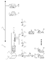
- FIG. 1 is a schematic diagram showing the overall configuration of a radio communication system according to the first embodiment (uplink communication and downlink communication);
- FIG. 1 is a schematic diagram showing the overall configuration of a radio communication system according to the first embodiment (communication between radio communication terminals);
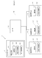
- FIG. 2 is a block diagram showing the control configuration of a radio base station and a controller; A conversion table for IP addresses and wireless communication terminal identifiers.
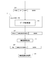
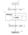
- Schematic diagram showing data conversion in a controller downlink communication
- Schematic diagram showing data conversion in a controller downlink communication
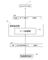
- Schematic diagram showing data conversion in a controller upstream communication).
- FIG. 4 is a flowchart showing data conversion control operation by a controller
- 6 is a schematic diagram showing the overall configuration of a radio communication system according to the second embodiment (uplink communication and downlink communication);
- FIG. FIG. 2 is a block diagram showing the control configuration of a radio base station and a controller; Schematic diagram showing data conversion in a radio base station (downlink communication). Schematic diagram showing data conversion in a radio base station (downlink communication). Schematic diagram showing data conversion in a radio base station (uplink communication).
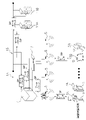
- FIG. 1 and 2 are schematic diagrams showing the overall configuration of a radio communication system according to the first embodiment of the present invention.
- the radio communication system 1 includes a plurality of first radio communication terminals 3A, a plurality of second radio communication terminals 3B, a plurality of radio base stations 5, and a controller 7.
- the first wireless communication terminal 3A and the second wireless communication terminal 3B are, for example, local 5G and WI-FI (registered trademark) communication units.
- the IP addresses of the first wireless communication terminal 3A and the second wireless communication terminal 3B are fixed addresses.
- the information specifying the first wireless communication terminal 3A and the second wireless communication terminal 3B is not limited to IP addresses.
- the information specifying the first wireless communication terminal 3A and the second wireless communication terminal 3B has a format that can be used by the communication protocol used in the wireless communication system 1. FIG.
- the first wireless communication terminal 3A is a group of wireless communication terminals provided in the factory, and is mounted, for example, on a plurality of carriages 9 (an example of moving bodies) in the factory. When the carriage 9 moves, the first radio communication terminal 3A may leave the communication range of the radio base station 5, but in that case, it enters the communication range of another radio base station 5 to continue communication. .
- the second wireless communication terminal 3B is a group of wireless communication terminals provided in the factory, different from the first wireless communication terminal 3A. ). In this embodiment, the number of first wireless communication terminals 3A is greater than the number of second wireless communication terminals 3B.
- the first wireless communication terminal 3A is an example of a "specific wireless communication terminal”
- the second wireless communication terminal 3B is an example of a "wireless communication terminal other than the specific wireless communication terminal”.
- the wireless communication system 1 constitutes part of a transport system having a plurality of transport vehicles 9 .
- external servers 11A and 11B are host systems and have information on the entire transportation vehicle 9 .
- the servers 11A and 11B transmit instructions for transporting packages to the plurality of carriages 9, and the carriages 9 transmit state, change, and position information of the carriages 9 to the servers 11A and 11B.
- the server 11A will be described as a representative example.
- the wireless communication system 1 transmits and receives data packets DP and data frames DF between devices.
- the data packet DP is, for example, a communication packet in a general-purpose communication protocol format transferred over Ethernet (registered trademark).
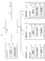
- FIG. 3 is a block diagram showing the control configuration of the radio base station and controller.
- the wireless base station 5 has a communication section 41 and a destination determination section 42 .
- the destination determination unit 42 is a function of the CPU that operates according to a program.
- the CPU may consist of a single processor, or may consist of a plurality of independent processors for each control.
- a part or all of the function of each element of the CPU may be realized as a program that can be executed by a computer system that constitutes the control unit.
- part of the function of each element of the control section may be configured by a custom IC. Note that the above description also applies to other CPUs.
- the wireless base station 5 wirelessly connects with a plurality of first wireless communication terminals 3A and second wireless communication terminals 3B.
- the radio base station 5 notifies the controller 7 that the first radio communication terminal 3A or the second radio communication terminal 3B has entered or left its own communication range.
- the controller 7 is a computer system comprising a CPU, RAM, ROM, etc., and performs overall control in the wireless communication system 1. Controller 7 communicates with first wireless communication terminal 3A or second wireless communication terminal 3B via wireless base station 5 . A router 13 is provided between the controller 7 and the plurality of radio base stations 5 . Note that in this embodiment, the controller 7 and the wireless base station 5 are connected by wire.
- the controller 7 is communicably connected to servers 11A and 11B (an example of another communication system) via a wired or wireless network 15 (an example of a predetermined network). As shown in FIG. 3, the controller 7 has a communication section 44, a destination determination section 45, and a data conversion section 46 (described later).
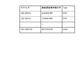
- the controller 7 grasps the IP addresses of the first wireless communication terminal 3A and the second wireless communication terminal 3B, and also determines to which wireless base station 5 each of the first wireless communication terminal 3A and the second wireless communication terminal 3B is connected. I know if there is. Specifically, the controller 7 has a table that associates IP addresses with wireless communication terminal identifiers, as shown in FIG. 4, and determines the wireless communication terminal identifier from the IP address.
- FIG. 4 is an example of a table that associates IP addresses with wireless communication terminal identifiers.
- the communication section 44, the destination determination section 45, and the data conversion section 46 implement transfer means 61 as a function executed by the CPU according to a program.
- the destination determination unit 45 determines the destination of the data packet DP. Based on the determination result of the destination determination unit 45, the communication unit 44 transfers the data packet DP as it is, or the data conversion unit 46 converts the data packet DP into a predetermined data frame DF (a packet after conversion). and then transfer (described later). In this way, the controller 7 can centrally manage transfer and conversion, so it is easy to deal with various changes.
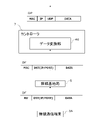
- a data frame DF for example, includes at least a header section and a data section.
- the data part includes, for example, a transport command including information on the source and destination of the article to be transported by the transport vehicle 9, a movement command including information on the destination to which the transport vehicle 9 should move, etc. It is composed of control data for controlling the carriage 9 .
- DATA of the data frame DF shown in FIG. 5 etc. corresponds to the data part.
- the header part contains information regarding the transmission source or transmission destination of the data contained in the data frame DF.
- the header of the data frame DF destined for the wireless communication terminal includes RU and SRC (IP/PORT).
- RU is a header called radio header.
- SRC (IP/PORT) is information indicating the source IP address (4 bytes) and its port number.
- the header portion of the data frame DF whose transmission source is the wireless communication terminal includes RU and DST (IP/PORT).
- DST (IP/PORT) is information indicating the destination IP address and its port number.
- the data frame DF is generated by replacing the header portion (MAC/IP/UDP) of the data packet DP with RU/SRC (IP/PORT) or RU/DST (IP/PORT).
- the size of the data portion is, for example, about 64 bytes
- the header portion of the data packet DP which is a communication packet of a general-purpose communication protocol format, has a size of about several tens of bytes.
- the size of the header portion of the data frame DF is smaller than the size of the header portion of the data packet DP. Therefore, by converting the data packet DP into the data frame DF, the packet size used for communication in the wireless communication terminal can be greatly reduced.
- the header of the data frame DF may or may not contain information about the sender. Also, the header portion of the data frame DF may be omitted. This allows a further significant reduction in packet size.
- FIG. 5 and 6 are schematic diagrams showing data conversion in the controller. 5 and 6 show communications addressed to the first wireless communication terminal 3A and the second wireless communication terminal 3B. Communication addressed to a wireless communication terminal is called “downlink communication”.
- downlink communication conventionally, the data packet DP transmitted from the server 11A is transmitted to the first wireless communication terminal 3A and the second wireless communication terminal 3B via the controller 7, the router 13, and the wireless base station 5. rice field.
- the data packet DP may or may not be converted into the data frame DF.
- the data conversion unit 46 of the controller 7 converts the data packet DP is converted into a predetermined data frame DF and transferred to the destination first wireless communication terminal 3A. Specifically, a predetermined data frame DF is transmitted to the first wireless communication terminal 3A via the router 13 and wireless base station 5.
- the data converter 46 converts the data packet DP into the data frame DF. Specifically, the header portion (MAC/IP/UDP) of the data packet DP is replaced with RU/SRC (IP/PORT) in the data frame DF. More specifically, the data conversion unit 46 recognizes the source of the data packet DP based on the information included in the header (MAC/IP/UDP) of the data packet DP, and based on the information about the source to generate the SRC (IP/PORT) of the data frame DF. After that, the data converter 46 replaces IP/UDP of the data packet DP with SRC (IP/PORT). Further, the radio base station 5 that has received the data frame DF replaces the MAC header of the data frame DF received from the controller 7 with the RU header.
- the data packet DP transmitted from the server 11A is the second wireless communication terminal 3B
- the data packet DP is not converted. Therefore, the overall processing load for conversion of the data packet DP does not become extremely large. In other words, data conversion is not performed uniformly, but is performed as necessary.
- a data packet DP destined for the first wireless communication terminal 3A is converted into a data frame DF with a relatively small capacity and transferred to the first wireless communication terminal 3A. , the communication load of the wireless communication system 1 can be reduced.
- control communication for industrial equipment requires real-time performance, and frequent transmission and reception of small amounts of data with low delay is required.
- first wireless communication terminals 3A since there are several hundred to several thousand first wireless communication terminals 3A in the factory, even a slight increase in data per terminal increases the total amount of communication.
- the overall data amount can be greatly reduced only by slightly reducing the data amount per unit involved in communication with the first wireless communication terminal 3A through the conversion described above.
- FIG. 7 is a schematic diagram showing data conversion in the controller.
- FIG. 7 shows communication originating from the first wireless communication terminal 3A. Communication originating from a wireless communication terminal is called “uplink communication”.
- uplink communication a data frame DF transmitted from the first wireless communication terminal 3A is converted into a data packet DP as necessary.
- the data conversion unit 46 converts the data frame DF into a data packet DP and transfers it to the server 11A.
- the transfer means 61 converts the predetermined data frame DF into the data packet DP.
- the data conversion unit 46 converts MAC/DST (IP/PORT) of the data frame DF into MAC/IP/UDP to generate the data packet DP. More specifically, the data conversion unit 46 determines the transmission destination of the data (DATA) included in the data frame DF based on the information included in the header portion (MAC/DST (IP/PORT)) of the data frame DF. The IP/UDP of the data packet DP is generated based on the grasped information about the destination. After that, the data converter 46 replaces DST (IP/PORT) of the data frame DF with the generated IP/UDP. Before the above process by the controller 7, the radio base station 5 that has received the data frame DF from the first radio communication terminal 3A replaces the RU header of the data frame DF with the MAC header.
- IP/PORT IP/PORT
- the transfer means 61 transfers the data frame DF is transferred to the first wireless communication terminal 3A without conversion.
- the data frame DF is transmitted to the other first wireless communication terminal 3A via the router 13, controller 7, router 13 and wireless base station 5.
- FIG. As described above, when the destination of the data frame DF received from the first wireless communication terminal 3A is another first wireless communication terminal 3A, the controller 7 transfers the data frame DF without conversion. Thereby, the processing load on the controller 7 can be reduced.
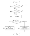
- FIG. 8 is a flow chart showing the data conversion control operation by the controller.
- the control flow chart described below is an example, and each step can be omitted or replaced as needed. Also, a plurality of steps may be executed simultaneously, or some or all of them may overlap.
- each block in the control flow chart is not limited to a single control operation, and can be replaced with a plurality of control operations represented by a plurality of blocks.
- the operation of each device is the result of commands from the control section to each device, and these are expressed by each step of the software application.
- step S1 the communication unit 44 of the controller 7 waits for the data packet DP to be received.
- step S2 it is determined whether or not data conversion is necessary. Specifically, the destination determination unit 45 makes the above determination. If data conversion is required, the process proceeds to step S3; otherwise, the process skips step S3 and proceeds to step S4.
- a case where data conversion is necessary is a case where the destination of the data contained in the data packet DP is the first wireless communication terminal 3A and the server 11A.
- a case where data conversion is not required is a case where the destination of the data contained in the data packet DP is the second wireless communication terminal 3B.
- the data packet DP is converted into a predetermined data frame DF.
- the data conversion unit 46 executes the above operation. Since the operation of converting the data packet DP into the data frame DF has already been explained above, the explanation is omitted here.
- step S4 the destination of the data packet DP or data frame DF is determined. Specifically, for example, the destination determining unit 45 determines the destination of the data packet DP or data frame DF based on the information about the destination included in the header of the data packet DP or data frame DF. If the destination is the server 11A, the process moves to step S5, and if the destination is the first wireless communication terminal 3A or the second wireless communication terminal 3B, the process moves to step S6.
- step S5 the data packet DP is transmitted to the destination server 11A. Specifically, the communication unit 44 executes the above operation.
- step S6 the data frame DF or data packet DP is transmitted to the destination first wireless communication terminal 3A or second wireless communication terminal 3B, respectively.
- the communication unit 44 executes the above operation.
- FIG. 9 is a schematic diagram showing the overall configuration of a radio communication system according to the second embodiment.
- FIG. 10 is a block diagram showing the control configuration of the radio base station and controller. The basic configuration and operation of the radio communication system 1A according to the second embodiment are the same as those of the first embodiment.
- the radio communication system 1A includes a plurality of first radio communication terminals 3A, a plurality of second radio communication terminals 3B, a plurality of radio base stations 5, and a controller 7.
- FIG. 10 is a block diagram showing the control configuration of the radio base station and controller.
- the radio base station 5 has a communication section 41 , a destination determination section 42 and a data conversion section 43 .
- the communication unit 41, the transmission destination determination unit 42, and the data conversion unit 43 implement transfer means 61A as a function executed by the CPU according to a program.
- the destination determination unit 42 determines the destination of the data packet DP. Based on the determination result of the destination determination unit 42, the communication unit 41 transfers the data packet DP as it is, or converts the data packet DP into a predetermined data frame DF by the data conversion unit 43 before transferring ( later). Since a plurality of radio base stations 5 can perform data conversion in this manner, the processing load can be distributed.
- FIG. 11 and 12 are schematic diagrams showing data conversion in the radio base station.
- data packets DP transmitted from the server 11A were conventionally transmitted to the first wireless communication terminal 3A or the second wireless communication terminal 3B via the controller 7, the router 13, and the wireless base station 5.
- the data packet DP may or may not be converted into the data frame DF.
- the controller 7 determines which radio base station 5 the communication range of the first radio communication terminal 3A or the second radio communication terminal 3B, which is the destination of the data packet DP transmitted from the server 11A, Send data packet DP to station 5;
- the data conversion unit 43 of the radio base station 5 converts the data packet DP into a data frame DF. Specifically, the radio base station 5 replaces the header portion (MAC/IP/UDP) of the data packet DP with RU/SRC (IP/PORT) to generate the data frame DF.
- MAC/IP/UDP header portion of the data packet DP
- RU/SRC IP/PORT
- the data converter 43 of the radio base station 5 As an explanation of the case where conversion is not performed, the data converter 43 of the radio base station 5, as shown in FIG.
- the data packet DP is transferred to the second wireless communication terminal 3B without performing the above conversion. Note that the radio base station 5 replaces the MAC header of the data packet DP with the RU header.
- FIG. 13 is a schematic diagram showing data conversion in a radio base station.
- the data converter 43 of the radio base station 5 converts the data frame DF into the data packet DP.
- the header portion (RU/DST (IP/PORT)) of the data frame DF is replaced with MAC/IP/UDP to generate the data packet DP.
- the data packet DP is not converted. Therefore, the processing load for conversion of the data packet DP is reduced as a whole. In other words, data conversion is not performed uniformly, but is performed as necessary. Since the data packet DP is converted into a data frame DF having a relatively small capacity, the communication load of the wireless communication system 1A can be reduced.
- the present invention includes a plurality of wireless communication terminals, a wireless base station wirelessly connected to the wireless communication terminals, communicating with the wireless communication terminals via the wireless base stations, and communicating with another communication system via a predetermined network. It is widely applicable to wireless networks with communicatively connected controllers.
- Wireless communication system 3A Wireless communication terminal 3B: Wireless communication terminal 5: Wireless base station 7: Controller 9: Carrier 11A: Server 11B: Server 13: Router 15: Network 41: Communication unit 42: Destination determination unit 43 : Data conversion unit 44 : Communication unit 45 : Destination determination unit 46 : Data conversion unit 61 : Transfer means DF : Data frame DP : Data packet
Landscapes
- Engineering & Computer Science (AREA)
- Computer Security & Cryptography (AREA)
- Computer Networks & Wireless Communication (AREA)
- Signal Processing (AREA)
- Mobile Radio Communication Systems (AREA)
Abstract
Description
無線通信システムは、転送手段を備えている。
転送手段は、他の通信システムから送信されるデータパケットの宛先が複数の無線通信端末のうち特定の無線通信端末であった場合には、データパケットを所定のデータフレームに変換して当該無線通信端末に転送する。一方、転送手段は、他の通信システムから送信されるデータパケットの宛先が複数の無線通信端末のうち特定の無線通信端末以外の無線通信端末であった場合には、データパケットを前記所定のデータフレームに変換することなく当該無線通信端末に転送する。
転送手段は、他の通信システムから送信されるデータパケットの宛先が複数の無線通信端末のうち特定の無線通信端末であった場合には、データパケットを所定のデータフレームに変換して当該無線通信端末に無線接続された無線基地局に転送する。一方、転送手段は、他の通信システムから送信されるデータパケットの宛先が複数の無線通信端末のうち特定の無線通信端末以外の無線通信端末であった場合には、データパケットを前記所定のデータフレームに変換することなく当該無線通信端末に無線接続された無線基地局に転送する。
転送手段は、コントローラ経由で他の通信システムから送信されるデータパケットの宛先が複数の無線通信端末のうち特定の無線通信端末であった場合には、データパケットを所定のデータフレームに変換して当該無線通信端末に転送する。一方、転送手段は、コントローラ経由で他の通信システムから送信されるデータパケットの宛先が複数の無線通信端末のうち特定の無線通信端末以外の無線通信端末であった場合には、データパケットを前記所定のデータフレームに変換することなく当該無線通信端末に転送する。
◎他の通信システムから送信されるデータパケットの宛先が複数の無線通信端末のうち特定の無線通信端末であるか否かを判断するステップ。
◎特定の無線通信端末であった場合にはデータパケットを所定のデータフレームに変換し、特定の無線通信端末以外の無線通信端末であった場合にはデータパケットを変換しないステップ。
◎所定のデータフレーム又はデータパケットを当該無線通信端末に転送するステップ。
(1)無線通信システムの基本構成
図1~図2を用いて、本発明の第1実施形態に係る無線通信システム1を説明する。図1~図2は、本発明の第1実施形態に係る無線通信システムの全体構成を示す模式図である。無線通信システム1は、複数の第1無線通信端末3Aと、複数の第2無線通信端末3Bと、複数の無線基地局5と、コントローラ7とを備えている。
図3を用いて、無線基地局5及びコントローラ7の制御構成を説明する。図3は、無線基地局及びコントローラの制御構成を示すブロック図である。無線基地局5は、通信部41、及び送信先判断部42を有している。送信先判断部42は、プログラムに従って作動するCPUの機能である。CPUは、単一のプロセッサで構成されていてもよいが、各制御のために独立した複数のプロセッサから構成されていてもよい。CPUの各要素の機能は、一部又は全てが、制御部を構成するコンピュータシステムにて実行可能なプログラムとして実現されてもよい。その他、制御部の各要素の機能の一部は、カスタムICにより構成されていてもよい。なお、上記の説明は他のCPUにも当てはまる。
図3に示すように、通信部44、送信先判断部45及びデータ変換部46は、プログラムに従ってCPUが実行する機能として、転送手段61を実現している。送信先判断部45は、データパケットDPの宛先を判断する。通信部44は、送信先判断部45の判断結果に基づいて、データパケットDPをそのまま転送するか、又は、データ変換部46によりデータパケットDPを所定のデータフレームDF(変換後のパケット)に変換してから転送する(後述)。このように、コントローラ7が転送及び変換を集中管理できるので、各種変更に対応することが容易である。
図5~図6を用いて、コントローラ7におけるデータ変換を説明する。図5~図6は、コントローラにおけるデータ変換を示す模式図である。図5~図6は、第1無線通信端末3A及び第2無線通信端末3Bを宛先とした通信を示している。無線通信端末を宛先とした通信を「下り通信」と呼ぶ。下り通信では、従来は、サーバ11Aから送信されたデータパケットDPは、コントローラ7、ルータ13、及び無線基地局5を介して、第1無線通信端末3A及び第2無線通信端末3Bに送信されていた。本実施形態では、下記に説明するように、データパケットDPはデータフレームDFに変換される場合と、変換されない場合がある。
図7を用いて、第1無線通信端末3Aからの上り通信を説明する。図7は、コントローラにおけるデータ変換を示す模式図である。図7は、第1無線通信端末3Aを送信元とする通信を示している。無線通信端末を送信元とする通信を「上り通信」と呼ぶ。上り通信では、第1無線通信端末3Aから送信されたデータフレームDFは、必要に応じてデータパケットDPに変換される。
転送手段61は、第1無線通信端末3Aから送信されるデータフレームDFの宛先が他の第1無線通信端末3Aであった場合には、データフレームDFを変換することなく第1無線通信端末3Aに転送する。具体的には、データフレームDFは、ルータ13、コントローラ7、ルータ13及び無線基地局5を介して他の第1無線通信端末3Aに送信される。上記のように、第1無線通信端末3Aから受信したデータフレームDFの宛先が他の第1無線通信端末3Aであった場合は、コントローラ7はデータフレームDFを変換せずに転送する。これにより、コントローラ7の処理負荷を軽減できる。
図8を用いて、コントローラ7によるデータ変換制御動作を説明する。図8は、コントローラによるデータ変換制御動作を示すフローチャートである。以下に説明する制御フローチャートは例示であって、各ステップは必要に応じて省略及び入れ替え可能である。また、複数のステップが同時に実行されたり、一部又は全てが重なって実行されたりしてもよい。さらに、制御フローチャートの各ブロックは、単一の制御動作とは限らず、複数のブロックで表現される複数の制御動作に置き換えることができる。なお、各装置の動作は、制御部から各装置への指令の結果であり、これらはソフトウェア・アプリケーションの各ステップによって表現される。
第1実施形態では、転送手段61はコントローラ7に備えられていたが、転送手段61は無線基地局5に備えられていてもよい。図9及び図10を用いて、そのような実施例を第2実施形態として説明する。図9は、第2実施形態に係る無線通信システムの全体構成を示す模式図である。図10は、無線基地局及びコントローラの制御構成を示すブロック図である。なお、第2実施形態に係る無線通信システム1Aの基本的構成及び動作は第1実施形態と同じである。
以上、本発明の複数の実施形態について説明したが、本発明は上記実施形態に限定されるものではなく、発明の要旨を逸脱しない範囲で種々の変更が可能である。特に、本明細書に書かれた複数の実施形態及び変形例は必要に応じて任意に組み合せ可能である。
本発明は、搬送システム等の産業機器に最適であるが、他の装置やシステムにも適用できる。
データパケットのサイズを小さくするために、上記のヘッダの置換/削除に加えて又は代えて、一つのパケットに含まれるデータ量を小さくしてもよい。
3A :無線通信端末
3B :無線通信端末
5 :無線基地局
7 :コントローラ
9 :搬送台車
11A :サーバ
11B :サーバ
13 :ルータ
15 :ネットワーク
41 :通信部
42 :送信先判断部
43 :データ変換部
44 :通信部
45 :送信先判断部
46 :データ変換部
61 :転送手段
DF :データフレーム
DP :データパケット
Claims (10)
- 複数の無線通信端末と、
当該無線通信端末と無線接続する無線基地局と、
当該無線基地局を介して前記無線通信端末と通信すると共に、所定のネットワークを介して他の通信システムと通信可能に接続されるコントローラと、を備えた無線通信システムであって、
前記他の通信システムから送信されるデータパケットの宛先が前記複数の無線通信端末のうち特定の無線通信端末であった場合には、前記データパケットを所定のデータフレームに変換して当該無線通信端末に転送する一方、前記他の通信システムから送信されるデータパケットの宛先が前記複数の無線通信端末のうち前記特定の無線通信端末以外の無線通信端末であった場合には、前記データパケットを前記所定のデータフレームに変換することなく当該無線通信端末に転送する転送手段を備える、
無線通信システム。 - 前記転送手段は、特定の無線通信端末から送信される所定のデータフレームの宛先が他の通信システムであった場合は、前記所定のデータフレームを前記データパケットに変換して前記他の通信システムに転送する、請求項1に記載の無線通信システム。
- 複数の前記特定の無線通信端末を備え、
前記転送手段は、前記特定の無線通信端末から送信される所定のデータフレームの宛先が他の前記特定の無線通信端末であった場合には、前記所定のデータフレームを前記データパケットに変換することなく当該無線通信端末に転送する、請求項1又は2に記載の無線通信システム。 - 前記転送手段は、前記コントローラに備えられている、請求項1~3のいずれかに記載の無線通信システム。
- 前記転送手段は、前記無線基地局に備えられている、請求項1~3のいずれかに記載の無線通信システム。
- 前記データフレームは、宛先と、送信するデータ部と、を少なくとも含むデータフレームであり、
前記データパケットは、イーサネット上で転送される汎用的な通信プロトコルのフォーマットの通信パケットである、請求項1~5のいずれかに記載の無線通信システム。 - 前記無線通信端末は、移動体に搭載されたものである、請求項1~6のいずれかに記載の無線通信システム。
- 複数の無線通信端末と、前記無線通信端末と無線接続する無線基地局とを備えた無線通信システムにおいて用いられるコントローラであって、
前記無線基地局を介して前記無線通信端末と通信すると共に、所定のネットワークを介して他の通信システムと通信可能に接続され、
前記他の通信システムから送信されるデータパケットの宛先が前記複数の無線通信端末のうち特定の無線通信端末であった場合には、前記データパケットを所定のデータフレームに変換して当該無線通信端末に無線接続された無線基地局に転送する一方、前記他の通信システムから送信されるデータパケットの宛先が前記複数の無線通信端末のうち特定の無線通信端末以外の無線通信端末であった場合には、前記データパケットを前記所定のデータフレームに変換することなく当該無線通信端末に無線接続された無線基地局に転送する転送手段を有する、
コントローラ。 - 複数の無線通信端末と、所定のネットワークを介して他の通信システムと通信可能に接続されたコントローラとを備えた無線通信システムにおいて用いられる無線基地局であって、
前記無線通信端末と無線接続しており、前記コントローラに接続されており、
前記コントローラ経由で前記他の通信システムから送信されるデータパケットの宛先が前記複数の無線通信端末のうち特定の無線通信端末であった場合には、前記データパケットを所定のデータフレームに変換して当該無線通信端末に転送する一方、前記コントローラ経由で前記他の通信システムから送信されるデータパケットの宛先が前記複数の無線通信端末のうち特定の無線通信端末以外の無線通信端末であった場合には、前記データパケットを所定のデータフレームに変換することなく当該無線通信端末に転送する転送手段を有する、
無線基地局。 - 複数の無線通信端末と、当該無線通信端末と無線接続する無線基地局と、当該無線基地局を介して前記無線通信端末と通信すると共に、所定のネットワークを介して他の通信システムと通信可能に接続されるコントローラと、を備えた無線通信システムにおけるデータパケット転送方法であって、
前記他の通信システムから送信されるデータパケットの宛先が前記複数の無線通信端末のうち特定の無線通信端末であるか否かを判断するステップと、
前記特定の無線通信端末であった場合には前記データパケットを所定のデータフレームに変換し、前記特定の無線通信端末以外の無線通信端末であった場合には前記データパケットを変換しないステップと、
前記所定のデータフレーム又は前記データパケットを当該無線通信端末に転送するステップと、
を含む、データパケット転送方法。
Priority Applications (3)
| Application Number | Priority Date | Filing Date | Title |
|---|---|---|---|
| DE112022001263.3T DE112022001263T5 (de) | 2021-03-24 | 2022-02-17 | Drahtloskommunikationssystem, steuerung, drahtlosbasisstation und datenpaketübertragungsverfahren |
| US18/282,814 US20240171658A1 (en) | 2021-03-24 | 2022-02-17 | Wireless communication system, controller, wireless base station, and data packet transfer method |
| CN202280021543.4A CN117044186A (zh) | 2021-03-24 | 2022-02-17 | 无线通信系统、控制器、无线基站以及数据分组传送方法 |
Applications Claiming Priority (2)
| Application Number | Priority Date | Filing Date | Title |
|---|---|---|---|
| JP2021-050331 | 2021-03-24 | ||
| JP2021050331A JP7631960B2 (ja) | 2021-03-24 | 2021-03-24 | 無線通信システム、コントローラ、無線基地局、及びデータパケット転送方法 |
Publications (1)
| Publication Number | Publication Date |
|---|---|
| WO2022201997A1 true WO2022201997A1 (ja) | 2022-09-29 |
Family
ID=83396943
Family Applications (1)
| Application Number | Title | Priority Date | Filing Date |
|---|---|---|---|
| PCT/JP2022/006399 Ceased WO2022201997A1 (ja) | 2021-03-24 | 2022-02-17 | 無線通信システム、コントローラ、無線基地局、及びデータパケット転送方法 |
Country Status (5)
| Country | Link |
|---|---|
| US (1) | US20240171658A1 (ja) |
| JP (1) | JP7631960B2 (ja) |
| CN (1) | CN117044186A (ja) |
| DE (1) | DE112022001263T5 (ja) |
| WO (1) | WO2022201997A1 (ja) |
Citations (2)
| Publication number | Priority date | Publication date | Assignee | Title |
|---|---|---|---|---|
| WO2003100652A1 (en) * | 2002-05-28 | 2003-12-04 | Samsung Electronics Co., Ltd | Apparatus and method for broadcasting data within wireless communication service area |
| JP2019029994A (ja) * | 2017-07-26 | 2019-02-21 | パナソニック インテレクチュアル プロパティ コーポレーション オブ アメリカPanasonic Intellectual Property Corporation of America | 車載中継装置、車載監視装置、車載制御ネットワークシステム、通信監視方法及びプログラム |
Family Cites Families (3)
| Publication number | Priority date | Publication date | Assignee | Title |
|---|---|---|---|---|
| JP3775494B2 (ja) * | 2001-09-21 | 2006-05-17 | 日本電気株式会社 | 課金システムの情報処理装置、及び課金情報収集方法 |
| US20060221939A1 (en) * | 2005-03-31 | 2006-10-05 | Rosen Eric C | System and method for simultaneous voice and data call over wireless infrastructure |
| JP2019096924A (ja) * | 2017-11-17 | 2019-06-20 | 富士通株式会社 | 伝送装置、および伝送方法 |
-
2021
- 2021-03-24 JP JP2021050331A patent/JP7631960B2/ja active Active
-
2022
- 2022-02-17 US US18/282,814 patent/US20240171658A1/en not_active Abandoned
- 2022-02-17 WO PCT/JP2022/006399 patent/WO2022201997A1/ja not_active Ceased
- 2022-02-17 DE DE112022001263.3T patent/DE112022001263T5/de active Pending
- 2022-02-17 CN CN202280021543.4A patent/CN117044186A/zh active Pending
Patent Citations (2)
| Publication number | Priority date | Publication date | Assignee | Title |
|---|---|---|---|---|
| WO2003100652A1 (en) * | 2002-05-28 | 2003-12-04 | Samsung Electronics Co., Ltd | Apparatus and method for broadcasting data within wireless communication service area |
| JP2019029994A (ja) * | 2017-07-26 | 2019-02-21 | パナソニック インテレクチュアル プロパティ コーポレーション オブ アメリカPanasonic Intellectual Property Corporation of America | 車載中継装置、車載監視装置、車載制御ネットワークシステム、通信監視方法及びプログラム |
Also Published As
| Publication number | Publication date |
|---|---|
| US20240171658A1 (en) | 2024-05-23 |
| DE112022001263T5 (de) | 2023-12-21 |
| CN117044186A (zh) | 2023-11-10 |
| JP2022148589A (ja) | 2022-10-06 |
| JP7631960B2 (ja) | 2025-02-19 |
Similar Documents
| Publication | Publication Date | Title |
|---|---|---|
| US11616733B2 (en) | Method for controlling network congestion, access device, and computer readable storage medium | |
| US8107478B2 (en) | Wireless communication device, communication system, communication control method, and program | |
| US20180287815A1 (en) | In-vehicle gateway device | |
| US20150263862A1 (en) | Communication system, control apparatus, communication control method, transfer control method, and transfer control program | |
| JP7506128B2 (ja) | 無線ネットワークを介したコントローラと被制御デバイスとの間の通信 | |
| US20210321485A1 (en) | Mesh network system | |
| CN102014057A (zh) | 基于epa协议的支持实时和非实时应用的工业以太网通信方法 | |
| US10212258B2 (en) | Communication packet header data compression | |
| CN103685028A (zh) | 多类型端口相互通信的方法及装置 | |
| US7796601B1 (en) | Internet protocol data transfer over diverse paths | |
| US20220029751A1 (en) | Dynamic wireless network architecture to serve uplink-centric and downlink-centric user applications | |
| WO2022201997A1 (ja) | 無線通信システム、コントローラ、無線基地局、及びデータパケット転送方法 | |
| US11265798B2 (en) | Method and radio communication system for an industrial automation system | |
| WO2022201998A1 (ja) | 無線通信システム、無線基地局、及びデータパケット転送方法 | |
| US10320661B2 (en) | Communication device and communication method | |
| US10826825B2 (en) | Access network system, and data packet processing method and apparatus | |
| CN106330547B (zh) | 一种冗余链路数据包转发的方法及装置 | |
| US12301446B2 (en) | Communication device, communication system, communication method, and non-transitory computer readable medium storing communication program | |
| JP7293728B2 (ja) | パケットカプセル化方法およびパケットカプセル化装置 | |
| CN109428819B (zh) | 传输数据的方法、网络组件、设备和计算机存储介质 | |
| JP2019004206A (ja) | プロトコル変換装置、コンピュータプログラム、及び無線通信装置 | |
| CN116489688A (zh) | 一种组网系统、方法、计算机设备及存储介质 | |
| JP2000196668A (ja) | ル―タ装置、無線端末及び無線通信システム並びに通信方法 | |
| JP2007074198A (ja) | ネットワーク通信システム | |
| JP2019146065A (ja) | 無線通信装置、及び方法 |
Legal Events
| Date | Code | Title | Description |
|---|---|---|---|
| DPE2 | Request for preliminary examination filed before expiration of 19th month from priority date (pct application filed from 20040101) | ||
| 121 | Ep: the epo has been informed by wipo that ep was designated in this application |
Ref document number: 22774797 Country of ref document: EP Kind code of ref document: A1 |
|
| WWE | Wipo information: entry into national phase |
Ref document number: 202280021543.4 Country of ref document: CN |
|
| WWE | Wipo information: entry into national phase |
Ref document number: 18282814 Country of ref document: US |
|
| WWE | Wipo information: entry into national phase |
Ref document number: 112022001263 Country of ref document: DE |
|
| 122 | Ep: pct application non-entry in european phase |
Ref document number: 22774797 Country of ref document: EP Kind code of ref document: A1 |