WO2022201905A1 - Work machine - Google Patents
Work machine Download PDFInfo
- Publication number
- WO2022201905A1 WO2022201905A1 PCT/JP2022/004510 JP2022004510W WO2022201905A1 WO 2022201905 A1 WO2022201905 A1 WO 2022201905A1 JP 2022004510 W JP2022004510 W JP 2022004510W WO 2022201905 A1 WO2022201905 A1 WO 2022201905A1
- Authority
- WO
- WIPO (PCT)
- Prior art keywords
- time
- speed
- hydraulic
- target
- speed command
- Prior art date
Links
- 238000004364 calculation method Methods 0.000 claims abstract description 365
- 238000001514 detection method Methods 0.000 claims abstract description 70
- 238000006073 displacement reaction Methods 0.000 claims description 34
- 230000003111 delayed effect Effects 0.000 claims description 11
- 230000009471 action Effects 0.000 claims description 4
- 230000004044 response Effects 0.000 description 88
- 230000036544 posture Effects 0.000 description 69
- 238000010586 diagram Methods 0.000 description 46
- 238000000034 method Methods 0.000 description 20
- 230000008602 contraction Effects 0.000 description 14
- 238000009412 basement excavation Methods 0.000 description 13
- 230000000694 effects Effects 0.000 description 9
- 102220490348 S-adenosylhomocysteine hydrolase-like protein 1_S90A_mutation Human genes 0.000 description 7
- 102220398908 c.178T>G Human genes 0.000 description 6
- 230000010354 integration Effects 0.000 description 6
- 230000008569 process Effects 0.000 description 5
- 230000007704 transition Effects 0.000 description 5
- 102220490364 S-adenosylhomocysteine hydrolase-like protein 1_S80A_mutation Human genes 0.000 description 4
- 230000001934 delay Effects 0.000 description 4
- 230000009467 reduction Effects 0.000 description 4
- 102220490407 S-adenosylhomocysteine hydrolase-like protein 1_S70A_mutation Human genes 0.000 description 2
- 230000003213 activating effect Effects 0.000 description 2
- 230000008859 change Effects 0.000 description 2
- 230000005284 excitation Effects 0.000 description 2
- 230000004913 activation Effects 0.000 description 1
- 230000000903 blocking effect Effects 0.000 description 1
- 230000007423 decrease Effects 0.000 description 1
- 238000005516 engineering process Methods 0.000 description 1
- 238000005259 measurement Methods 0.000 description 1
- 230000004048 modification Effects 0.000 description 1
- 238000012986 modification Methods 0.000 description 1
- 230000002250 progressing effect Effects 0.000 description 1
- 230000000087 stabilizing effect Effects 0.000 description 1
Images


Classifications
-
- E—FIXED CONSTRUCTIONS
- E02—HYDRAULIC ENGINEERING; FOUNDATIONS; SOIL SHIFTING
- E02F—DREDGING; SOIL-SHIFTING
- E02F9/00—Component parts of dredgers or soil-shifting machines, not restricted to one of the kinds covered by groups E02F3/00 - E02F7/00
- E02F9/20—Drives; Control devices
- E02F9/22—Hydraulic or pneumatic drives
- E02F9/2278—Hydraulic circuits
- E02F9/2285—Pilot-operated systems
-
- E—FIXED CONSTRUCTIONS
- E02—HYDRAULIC ENGINEERING; FOUNDATIONS; SOIL SHIFTING
- E02F—DREDGING; SOIL-SHIFTING
- E02F9/00—Component parts of dredgers or soil-shifting machines, not restricted to one of the kinds covered by groups E02F3/00 - E02F7/00
- E02F9/20—Drives; Control devices
- E02F9/22—Hydraulic or pneumatic drives
- E02F9/2278—Hydraulic circuits
-
- E—FIXED CONSTRUCTIONS
- E02—HYDRAULIC ENGINEERING; FOUNDATIONS; SOIL SHIFTING
- E02F—DREDGING; SOIL-SHIFTING
- E02F9/00—Component parts of dredgers or soil-shifting machines, not restricted to one of the kinds covered by groups E02F3/00 - E02F7/00
- E02F9/20—Drives; Control devices
- E02F9/22—Hydraulic or pneumatic drives
- E02F9/2221—Control of flow rate; Load sensing arrangements
-
- E—FIXED CONSTRUCTIONS
- E02—HYDRAULIC ENGINEERING; FOUNDATIONS; SOIL SHIFTING
- E02F—DREDGING; SOIL-SHIFTING
- E02F3/00—Dredgers; Soil-shifting machines
- E02F3/04—Dredgers; Soil-shifting machines mechanically-driven
- E02F3/28—Dredgers; Soil-shifting machines mechanically-driven with digging tools mounted on a dipper- or bucket-arm, i.e. there is either one arm or a pair of arms, e.g. dippers, buckets
- E02F3/36—Component parts
- E02F3/42—Drives for dippers, buckets, dipper-arms or bucket-arms
- E02F3/43—Control of dipper or bucket position; Control of sequence of drive operations
-
- E—FIXED CONSTRUCTIONS
- E02—HYDRAULIC ENGINEERING; FOUNDATIONS; SOIL SHIFTING
- E02F—DREDGING; SOIL-SHIFTING
- E02F9/00—Component parts of dredgers or soil-shifting machines, not restricted to one of the kinds covered by groups E02F3/00 - E02F7/00
- E02F9/20—Drives; Control devices
- E02F9/2025—Particular purposes of control systems not otherwise provided for
-
- E—FIXED CONSTRUCTIONS
- E02—HYDRAULIC ENGINEERING; FOUNDATIONS; SOIL SHIFTING
- E02F—DREDGING; SOIL-SHIFTING
- E02F9/00—Component parts of dredgers or soil-shifting machines, not restricted to one of the kinds covered by groups E02F3/00 - E02F7/00
- E02F9/20—Drives; Control devices
- E02F9/22—Hydraulic or pneumatic drives
- E02F9/2203—Arrangements for controlling the attitude of actuators, e.g. speed, floating function
-
- E—FIXED CONSTRUCTIONS
- E02—HYDRAULIC ENGINEERING; FOUNDATIONS; SOIL SHIFTING
- E02F—DREDGING; SOIL-SHIFTING
- E02F9/00—Component parts of dredgers or soil-shifting machines, not restricted to one of the kinds covered by groups E02F3/00 - E02F7/00
- E02F9/26—Indicating devices
-
- E—FIXED CONSTRUCTIONS
- E02—HYDRAULIC ENGINEERING; FOUNDATIONS; SOIL SHIFTING
- E02F—DREDGING; SOIL-SHIFTING
- E02F9/00—Component parts of dredgers or soil-shifting machines, not restricted to one of the kinds covered by groups E02F3/00 - E02F7/00
- E02F9/26—Indicating devices
- E02F9/264—Sensors and their calibration for indicating the position of the work tool
- E02F9/265—Sensors and their calibration for indicating the position of the work tool with follow-up actions (e.g. control signals sent to actuate the work tool)
-
- B—PERFORMING OPERATIONS; TRANSPORTING
- B60—VEHICLES IN GENERAL
- B60Y—INDEXING SCHEME RELATING TO ASPECTS CROSS-CUTTING VEHICLE TECHNOLOGY
- B60Y2200/00—Type of vehicle
- B60Y2200/40—Special vehicles
- B60Y2200/41—Construction vehicles, e.g. graders, excavators
- B60Y2200/412—Excavators
Definitions
- the present invention relates to a working machine equipped with a working device, and more particularly to a working machine that controls the operation of the working device under predetermined conditions.
- a working machine is equipped with a working device driven by a hydraulic actuator.
- a technique called machine control (MC) is available as a technique for improving the working efficiency of working machines.
- MC is a technique of assisting an operator's operation by executing semi-automatic control for operating a working device according to predetermined conditions when the operating device is operated by the operator.
- control is executed to operate the working device along a predetermined reference plane. In this case, it is required to stably operate the hydraulic actuator at the target speed.
- Patent Literature 1 discloses that a hydraulic actuator (for example, an arm cylinder) that drives a work device is prevented from delaying the response (for example, a boom-up command) of the MC to the actual start of movement, thereby preventing the behavior of the work device in the MC.
- a hydraulic actuator for example, an arm cylinder
- the control device executes MC based on the arm cylinder speed calculated from the detection value of the attitude detection device.
- the control device executes MC based on the arm cylinder speed calculated from the operation amount of the operating device.
- the speed calculated from the detected value of the attitude detection device is usually closer to the actual speed than the speed calculated from the operation amount of the controller device.
- the posture detection device cannot detect a change in posture unless the work implement actually moves, if MC is executed based on the detection value of the posture detection device, the response of MC to the start of arm movement is I will be late. Therefore, only when the arm starts to move, MC is executed based on the arm cylinder speed calculated from the operation amount of the operating device.
- the MC needs to control the speed of the hydraulic actuator with high precision.
- the actual speed of the hydraulic actuator has a delayed response to the speed command of the control device for driving the hydraulic actuator. This is because there are a number of processes from when the control signal of the control device is output until the hydraulic actuator is actually driven at a speed corresponding to the speed command of the control device.
- the pump displacement of the hydraulic pump is changed according to the speed command for the hydraulic actuator, and the flow control valve corresponding to the hydraulic actuator is driven according to the speed command.
- the pressure oil discharged from the hydraulic pump whose pump volume has been changed is supplied to the hydraulic actuator through the driven flow control valve, and the pressure in the hydraulic actuator increases, thereby changing the speed of the hydraulic actuator. .
- the present invention has been made based on the above matter, and its object is to reduce the influence of the response delay of the actual speed with respect to the speed command of the hydraulic actuator, thereby improving the operation accuracy of the work equipment in the MC. It is to provide the machine.
- the present application includes a plurality of means for solving the above problems.
- a working device that performs work, a plurality of hydraulic actuators that drive the working device, and pressure oil to the plurality of hydraulic actuators.
- a supply hydraulic pump a plurality of control valves for respectively controlling the flow of pressure oil supplied from the hydraulic pump to each of the plurality of hydraulic actuators, an attitude detection device for detecting the attitude of the working device,
- a controller that calculates a speed command for each of the plurality of actuators in each calculation cycle, and outputs a control signal for controlling each of the plurality of hydraulic actuators based on the calculated speed command for each of the plurality of hydraulic actuators.
- the controller controls the operation of the first hydraulic actuator under a predetermined condition according to the operation of the second hydraulic actuator, the position detection device Based on the detection signal, the actual speed of each of the plurality of hydraulic actuators in the current calculation cycle is calculated, and the actual speed of each of the plurality of hydraulic actuators as a result of the calculation and the calculation is performed in a calculation cycle earlier than the current calculation cycle.
- the speed command for the first hydraulic actuator in the current calculation cycle that satisfies the conditions
- calculate the current speed command for the first hydraulic actuator as a result of calculation It is characterized by outputting a control signal for controlling the first hydraulic actuator based on the speed command of the calculation period.
- the actual velocity of each hydraulic actuator calculated based on the detection signal of the posture detection device in the current calculation period, and the speed command of each hydraulic actuator calculated in the calculation period previous to the current calculation period Since the past history is used to calculate the speed command for the first hydraulic actuator in the current calculation cycle that satisfies the predetermined conditions, the speed command for the first hydraulic actuator is calculated with consideration given to the response delay of the actual speed with respect to the speed command. can do. Therefore, it is possible to reduce the influence of the delay in the response of the actual speed to the speed command of the hydraulic actuator, thereby improving the operating accuracy of the work implement in the MC. Problems, configurations, and effects other than those described above will be clarified by the following description of the embodiments.
- FIG. 1 is a perspective view showing a hydraulic excavator to which a working machine according to a first embodiment of the present invention is applied;
- FIG. 1 is a hydraulic circuit diagram showing a hydraulic system mounted on a working machine according to a first embodiment of the present invention;
- FIG. 2 is a block diagram showing hardware and functions of a controller forming part of the first embodiment of the working machine of the present invention;
- 4 is a block diagram showing functions of an MC calculation unit of the controller shown in FIG. 3;
- FIG. 5 is a flow chart showing an example of a calculation processing procedure in a speed/posture prediction unit and a speed command calculation unit of the controller shown in FIG. 4;
- FIG. 1 is a perspective view showing a hydraulic excavator to which a working machine according to a first embodiment of the present invention is applied;
- FIG. 1 is a hydraulic circuit diagram showing a hydraulic system mounted on a working machine according to a first embodiment of the present invention;
- FIG. 2 is a block diagram showing hardware and
- FIG. 5 is an explanatory diagram showing a calculation method of a speed/posture prediction unit and a speed command calculation unit of the controller shown in FIG. 4;
- FIG. 4 is an explanatory diagram showing the relationship between the target speed, speed command, and actual speed of each hydraulic actuator during execution of MC with respect to arm-crowd operation in the first embodiment of the working machine of the present invention;
- FIG. 7 is a block diagram showing functions of an MC calculation section of a controller forming part of the second embodiment of the working machine of the present invention; 9 is a flow chart showing an example of a calculation processing procedure in a speed/posture prediction unit and a speed command calculation unit of the controller shown in FIG. 8;
- FIG. 8 is an explanatory diagram showing a calculation method of a speed/posture prediction unit and a speed command calculation unit of the controller shown in FIG. 8;
- FIG. 9 is an explanatory diagram showing a calculation method of a speed/attitude prediction unit and a speed command calculation unit of the controller shown in FIG. 8;
- FIG. 9 is an explanatory diagram showing the relationship between the target speed, speed command, and actual speed of each hydraulic actuator during execution of MC with respect to arm crowding operation in the second embodiment of the working machine of the present invention;
- FIG. 11 is a block diagram showing functions of an MC calculation section of a controller forming part of a working machine according to a third embodiment of the present invention;
- FIG. 13 is a flow chart showing an example of an arithmetic processing procedure in an actuator control section of the controller shown in FIG. 12;
- FIG. 13 is a flow chart showing an example of an arithmetic processing procedure in a hydraulic pump control section of the controller shown in FIG. 12;
- FIG. FIG. 11 is an explanatory diagram showing the relationship between pilot pressure information of a control valve and pump volume information of a hydraulic pump with respect to speed information of a hydraulic actuator during execution of MC in the working machine according to the third embodiment of the present invention;
- FIG. 1 is a perspective view showing a hydraulic excavator to which the first embodiment of the working machine of the present invention is applied.
- FIG. 1 is a perspective view showing a hydraulic excavator to which the first embodiment of the working machine of the present invention is applied.
- the directions viewed from the operator seated in the driver's seat will be described.
- a hydraulic excavator as a working machine includes a front working device 1 for performing work such as excavation, and a machine body 2 to which the front working device 1 is rotatably attached.
- the machine body 2 is composed of a self-propelled undercarriage 3 and an upper revolving body 4 mounted on the undercarriage 3 so as to be able to turn.
- the front working device 1 is a multi-joint working device configured by connecting a plurality of driven members so as to be rotatable in the vertical direction.
- a plurality of driven members are composed of, for example, a boom 11, an arm 12, and a bucket 13 as a working tool.
- a base end portion of the boom 11 is rotatably supported by a front portion of the upper swing body 4 via a boom pin (not shown).
- a proximal end of an arm 12 is rotatably supported at the distal end of the boom 11 via an arm pin (not shown).
- a bucket 13 is rotatably supported at the tip of the arm 12 via a bucket pin 13a.
- the boom 11, the arm 12, and the bucket 13 are driven by a boom cylinder 15, an arm cylinder 16, and a bucket cylinder 17, which are hydraulic actuators, respectively.
- the bucket 13 is driven via a link member 18 that rotates in conjunction with the bucket 13 .
- the lower traveling body 3 has, for example, crawler-type traveling devices 21 (only the left side is shown) on the left and right sides.
- the travel device 21 is driven by a travel hydraulic motor 21a, which is a hydraulic actuator.
- the upper revolving structure 4 is configured to be driven to revolve relative to the lower traveling structure 3 by, for example, a revolving hydraulic motor 6, which is a hydraulic actuator.
- the upper revolving body 4 includes an operator's cab 23 in which an operator rides and a machine room 24 in which various devices are housed.
- the operation device 25 has operation levers 25a and 25b that can be tilted forward, backward, leftward, and rightward. Operation of the operation levers 25a and 25b in the front-rear direction and operation in the left-right direction are assigned as operations of different hydraulic actuators. For example, each operation of the operation levers 25a and 25b is assigned as operation of the front work device 1 (boom cylinder 15, arm cylinder 16, bucket cylinder 17), swing operation of the upper swing body 4 (swing hydraulic motor 6), and the like.
- the operating device 26 has left and right travel pedals 26a and 26b and left and right travel levers 26c and 26d which are tiltable forward and backward and interlocked with the operation of the travel pedals 26a and 26b.
- the left and right travel pedals 26a, 26b and travel levers 26c, 26d are assigned as travel operations for the left and right travel devices 21 (travel hydraulic motors 21a). Details of the operating device will be described later.
- a display device 27 (see FIG. 3, which will be described later) is arranged in the operator's cab 23 to display various types of information about the hydraulic excavator, setting screens, and the like.
- a prime mover 41 In the machine room 24, a prime mover 41, a hydraulic pump 42, a pilot pump 43 (see later-described FIG. 2), etc. are arranged. Further, a control valve unit 44, which is an assembly of a plurality of control valves including a flow control valve (see FIG. 2, which will be described later), is arranged.
- a boom angle sensor 31 is installed on the boom 11 to detect physical quantities (attitude information) relating to the attitude of the boom 11 .
- the boom angle sensor 31 is, for example, a rotary potentiometer attached to a boom pin that is a connecting portion between the boom 11 and the upper rotating body 4, and detects the relative rotation angle (boom angle) of the boom 11 with respect to the upper rotating body 4. do.
- the arm 12 is provided with an arm angle sensor 32 that detects a physical quantity (posture information) regarding the posture of the arm 12 .
- the arm angle sensor 32 is, for example, a rotary potentiometer attached to an arm pin that connects the boom 11 and the arm 12 , and detects the relative rotation angle (arm angle) of the arm 12 with respect to the boom 11 .
- the bucket 13 is provided with a bucket angle sensor 33 that detects a physical quantity (posture information) regarding the posture of the bucket 13 .
- the bucket angle sensor 33 is, for example, a rotary potentiometer attached to the link member 18 and detects the relative rotation angle (bucket angle) of the bucket 13 with respect to the arm 12 .
- a fuselage tilt angle sensor 34 that detects a physical quantity (attitude information) regarding the attitude of the fuselage 2 is installed on the upper swing body 4 .
- the body tilt angle sensor 34 detects the tilt angle (body angle) of the upper revolving structure 4 (body 2) with respect to a reference plane (for example, horizontal plane).
- the four sensors of the boom angle sensor 31, the arm angle sensor 32, the bucket angle sensor 33, and the machine body tilt angle sensor 34 constitute an attitude detection device 30 that detects physical quantities (attitude information) related to the attitude of the front working device 1.
- the sensors 31 to 34 as the attitude detection device 30 transmit detection values (detection signals) of attitude information (boom angle, arm angle, bucket angle, machine body angle) of the front working device 1 to a controller 80 (described later in FIG. 3). reference).
- the angle sensors 31-33 can be replaced by tilt angle sensors, inertial measurement units (IMU), or stroke sensors that can be installed on the hydraulic cylinders 15-17.
- IMU inertial measurement units
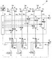
- FIG. 2 is a hydraulic circuit diagram showing a hydraulic system mounted on the first embodiment of the working machine of the present invention.
- the hydraulic excavator includes a hydraulic system 40 that hydraulically drives the front working device 1, the lower travel body 3, and the upper revolving body 4 (see FIG. 1 for both). 2 shows only hydraulic circuits related to the boom cylinder 15, the arm cylinder 16, and the bucket cylinder 17, which are hydraulic actuators for driving the front work device 1. A hydraulic circuit for the swing hydraulic motor 6 that drives the swing body 4 is omitted.
- the hydraulic system 40 includes a hydraulic pump 42 driven by a prime mover 41, and a plurality of hydraulic actuators (boom cylinder 15, arm cylinder 16, and bucket cylinder 17 in FIG. 2) driven by pressure oil discharged from the hydraulic pump 42. It has The hydraulic pump 42 is, for example, a variable displacement pump, and has a regulator 42a that controls the pump displacement. The regulator 42a adjusts the pump volume according to a control signal from the controller 80, for example. The pressure oil discharged by the hydraulic pump 42 is supplied via flow control valves 45-47 corresponding to the respective hydraulic actuators 15-17.
- the first flow control valve 45 controls the direction and flow rate of pressure oil supplied from the hydraulic pump 42 to the boom cylinder 15 .
- the first flow control valve 45 is of a hydraulic pilot type, and has pressure receiving portions 45a and 45b on both sides on which pilot pressure acts.
- the second flow control valve 46 controls the direction and flow rate of pressure oil supplied from the hydraulic pump 42 to the arm cylinder 16 .
- the second flow control valve 46 is of a hydraulic pilot type, and has pressure receiving portions 46a and 46b on both sides on which pilot pressure acts.
- the third flow control valve 47 controls the direction and flow rate of pressure oil supplied from the hydraulic pump 42 to the bucket cylinder 17 .
- the third flow control valve 47 is of a hydraulic pilot type, and has pressure receiving portions 47a and 47b on both sides on which pilot pressure acts.
- the boom cylinder 15 is driven by operating the first operating device 51
- the arm cylinder 16 is driven by operating the second operating device 52
- the third operating device 53 is operated to drive the boom cylinder 15.
- the bucket cylinder 17 is configured to be driven.
- the first operating device 51 and the third operating device 53 share, for example, the operating lever 25b shown in FIG. It is configured as a cross-operating lever device 25 that instructs an operation and instructs an operation of the other of the boom cylinder 15 and the bucket cylinder 17 by a tilting operation in the left-right direction.
- the second operating device 52 and the operating device for turning operation (not shown) share, for example, the operating lever 25a shown in FIG. It is configured as a cross-operating lever device 25 that instructs the operation of one of them and also instructs the operation of the other of the arm cylinder 16 and the turning hydraulic motor 6 by tilting in the left-right direction.
- Each operating device 51 to 53 is, for example, a hydraulic pilot type, and includes a pair of pressure reducing valves. Each of the operating devices 51 to 53 uses the discharge pressure of the pilot pump 43 as a source pressure to generate a pilot pressure (sometimes referred to as an operating pressure) according to the amount and direction of operation of the operating levers 25a and 25b. In FIG. 2, pilot discharge lines connecting the pilot pump 43 and the operating devices 51 to 53 are omitted.
- One pressure receiving portion 45a of the first flow control valve 45 is connected to the first operating device 51 via one first pilot line 55a, and the other pressure receiving portion 45a of the first flow control valve 45 is connected to the first operating device 51 via one first pilot line 55a.
- 45b is connected via the other first pilot line 55b.
- the operating pressure (pilot pressure) output from the first operating device 51 is used as an operating signal (sometimes referred to as a first operating signal) for driving the first flow control valve 45 .
- a first electromagnetic proportional valve 61 (boom lowering deceleration valve) is provided on one of the first pilot lines 55a.
- the first electromagnetic proportional valve 61 reduces the pilot pressure (operating pressure) output from the first operating device 51 based on the control signal from the controller 80 and outputs an operating signal (sometimes referred to as a second operating signal). , is output to one pressure receiving portion 45 a of the first flow control valve 45 .
- a pilot pressure first operation signal or second operation signal
- pressure oil from the hydraulic pump 42 is supplied to the rod side of the boom cylinder 15 .
- the first flow control valve 45 is driven in the direction in which the boom cylinder 15 is retracted, and the boom is lowered.
- a discharge line 58 of the pilot pump 43 is connected via a first shuttle valve 71 to the other first pilot line 55b.
- a second electromagnetic proportional valve 62 boost raising speed increasing valve
- the second electromagnetic proportional valve 62 reduces the discharge pressure of the pilot pump 43 based on the control signal from the controller 80 and generates the pilot pressure as an operation signal (sometimes referred to as a second operation signal). It outputs to The primary side port of the first shuttle valve 71 is connected to the first operating device 51 via the other first pilot line 55b, and connected to the secondary port of the second electromagnetic proportional valve 62 via the discharge line 58.
- the secondary port side is connected to the other pressure receiving portion 45b of the first flow control valve 45 via the other first pilot line 55b. That is, the first shuttle valve 71 selects the pilot pressure (first operation signal) output from the first operating device 51 or the pilot pressure (second operation signal) output from the second electromagnetic proportional valve 62. It selects the pilot pressure on the high pressure side and outputs it to the other pressure receiving portion 45 b of the first flow control valve 45 .
- a pilot pressure first operation signal or second operation signal
- pressure oil from the hydraulic pump 42 is supplied to the bottom side of the boom cylinder 15. Then, the first flow control valve 45 is driven in the direction in which the boom cylinder 15 is driven to extend, and the boom is raised.
- One pressure receiving portion 46a of the second flow control valve 46 is connected to the second operating device 52 via one second pilot line 56a, and the other pressure receiving portion 46a of the second flow control valve 46 is connected to the second operating device 52. 46b is connected via the other second pilot line 56b.
- the operating pressure (pilot pressure) output from the second operating device 52 is used as an operating signal (sometimes referred to as a first operating signal) for driving the second flow control valve 46 .
- a third electromagnetic proportional valve 63 (arm dump reduction valve) is provided on one of the second pilot lines 56a.
- the third electromagnetic proportional valve 63 reduces the pilot pressure (operating pressure) output from the second operating device 52 based on the control signal from the controller 80 and outputs an operating signal (sometimes referred to as a second operating signal). , is output to one pressure receiving portion 46 a of the second flow control valve 46 .
- a pilot pressure first operation signal or second operation signal
- pressure oil from the hydraulic pump 42 is supplied to the rod side of the arm cylinder 16. Then, the second flow control valve 46 is driven in the direction in which the arm cylinder 16 is retracted, and the arm dump operation is performed.
- a fourth electromagnetic proportional valve 64 (arm crowd reduction valve) is provided on the other second pilot line 56b.
- the fourth electromagnetic proportional valve 64 reduces the pilot pressure (manipulation pressure) output from the second operating device 52 based on the control signal from the controller 80 to produce the second flow rate as the manipulation signal (second manipulation signal). It outputs to the other pressure receiving portion 46 b of the control valve 46 .
- a pilot pressure first operation signal or second operation signal
- pressure oil from the hydraulic pump 42 is supplied to the bottom side of the arm cylinder 16.
- the second flow control valve 46 is driven in the direction in which the arm cylinder 16 is driven to extend, and the arm crowding operation is performed.
- One pressure receiving portion 47a of the third flow control valve 47 is connected to the third operating device 53 via one third pilot line 57a, and the other pressure receiving portion 47a of the third flow control valve 47 is connected to the third operation device 53 via one third pilot line 57a. 47b is connected via the other third pilot line 57b.
- the operating pressure (pilot pressure) output from the third operating device 53 is used as an operating signal (sometimes referred to as a first operating signal) for driving the third flow control valve 47 .
- a fifth electromagnetic proportional valve 65 (bucket dump reduction valve) is provided on one third pilot line 57a.
- a discharge line 58 of the pilot pump 43 is connected via a second shuttle valve 72 to a portion of the third pilot line 57 a downstream of the fifth electromagnetic proportional valve 65 .
- a sixth electromagnetic proportional valve 66 (bucket dump speed increasing valve) is provided on the discharge line 58 connected to the second shuttle valve 72 .
- the fifth electromagnetic proportional valve 65 reduces the pilot pressure (operating pressure) output from the third operating device 53 based on the control signal from the controller 80, and outputs the second shuttle pressure as an operating signal (second operating signal). It outputs to valve 72 .
- the sixth electromagnetic proportional valve 66 outputs the pilot pressure generated by reducing the discharge pressure of the pilot pump 43 based on the control signal from the controller 80 to the second shuttle valve 72 as an operation signal (second operation signal). be.
- the second shuttle valve 72 has its primary side port connected to the secondary port side of the fifth electromagnetic proportional valve 65 through one third pilot line 57a and to the sixth electromagnetic proportional valve 65 through the discharge line 58. It is connected to the secondary port side of the valve 66, and the secondary port side is connected to one pressure receiving portion 47a of the third flow control valve 47 via one third pilot line 57a.
- the second shuttle valve 72 is controlled by the pilot pressure (first operation signal or second operation signal) output from the fifth proportional electromagnetic valve 65 and the pilot pressure (first operation signal) output from the sixth proportional electromagnetic valve 66 2 operation signals), the pilot pressure on the high pressure side is selected and output to one pressure receiving portion 47 a of the third flow control valve 47 .
- a pilot pressure first operation signal or second operation signal
- pressure oil from the hydraulic pump 42 is supplied to the rod side of the bucket cylinder 17.
- the third flow control valve 47 is driven in the direction in which the bucket cylinder 17 is retracted, and the bucket dump operation is performed.
- a seventh electromagnetic proportional valve 67 (bucket cloud reduction valve) is provided on the other third pilot line 57b.
- a discharge line 58 of the pilot pump 43 is connected via a third shuttle valve 73 to a portion of the third pilot line 57b on the downstream side of the seventh electromagnetic proportional valve 67 .
- An eighth electromagnetic proportional valve 68 (bucket cloud speed increasing valve) is provided on the discharge line 58 connected to the third shuttle valve 73 .
- the seventh electromagnetic proportional valve 67 reduces the pilot pressure (operating pressure) output from the third operating device 53 based on the control signal from the controller 80, and outputs the third shuttle pressure as an operating signal (second operating signal). It outputs to the valve 73 .
- the eighth electromagnetic proportional valve 68 outputs the pilot pressure generated by reducing the discharge pressure of the pilot pump 43 based on the control signal from the controller 80 to the third shuttle valve 73 as an operation signal (second operation signal). be.
- the primary side port of the third shuttle valve 73 is connected to the secondary port side of the seventh proportional solenoid valve 67 through the other third pilot line 57b, and is connected to the eighth proportional solenoid valve through the discharge line 58. 68 valve, and the secondary port side is connected to the other pressure receiving portion 47b of the third flow control valve 47 via the other third pilot line 57b.
- the third shuttle valve 73 is controlled by the pilot pressure (first operation signal or second operation signal) output from the seventh proportional electromagnetic valve 67 and the pilot pressure (first operation signal) output from the eighth proportional electromagnetic valve 68. 2 operation signals), the pilot pressure on the high pressure side is selected and output to the other pressure receiving portion 47b of the third flow control valve 47.
- a pilot pressure first operation signal or second operation signal
- pressure oil from the hydraulic pump 42 is supplied to the bottom side of the bucket cylinder 17.
- the third flow control valve 47 is driven in the direction in which the bucket cylinder 17 is driven to extend, and the bucket cloud operation is performed.
- Each of the electromagnetic proportional valves 61 to 68 is electrically connected to the controller 80, and the opening is controlled by the excitation current (control signal) from the controller 80.
- the first, third, fourth, fifth, and seventh proportional solenoid valves 61, 63, 64, 65, and 67 are, for example, normally open solenoid valves whose opening is maximized when not energized. The opening decreases to the minimum opening (for example, opening 0) in proportion to the increase in the exciting current (control signal) from 80 .
- the second, sixth, and eighth proportional electromagnetic valves 62, 66, and 68 are normally closed electromagnetic valves that have a minimum opening degree (for example, an opening degree of 0) when not energized. The opening increases to the maximum opening in proportion to the increase in current (control signal).
- the second, sixth and eighth electromagnetic proportional valves 62, 66 and 68 are driven by control signals from the controller 80, the corresponding operating devices 51 and 53 are not operated.
- the discharge pressure of the pilot pump 43 is used as the source pressure to generate the pilot pressure as the second operation signal without operating the operation devices 51 and 53, and the other pressure receiving portion 45b of the first flow control valve 45 is generated.
- the second operation signal can be applied to one or the other pressure receiving portions 47 a and 47 b of the third flow control valve 47 . Therefore, the boom raising operation and the bucket cloud/dump operation can be forcibly executed.
- a pilot (second operation signal) is generated by reducing the operation pressure generated by the operation of the operation devices 51 to 53.
- One pressure receiving portion 45a of the first flow control valve 45, one or the other pressure receiving portions 46a and 46b of the second flow control valve 46, and one or the other pressure receiving portions 47a and 47b of the third flow control valve 47 can be applied. Therefore, the speed of the boom lowering operation, the arm crowding/dumping operation, and the bucket crowding/dumping operation can be forcibly reduced from the speed based on the operation amount of the operating devices 51-53.
- first and the other first pilot lines 55a and 55b are provided with first and second pressure sensors 75a and 75b for detecting the pilot pressure (first operation signal) generated by the first operating device 51, respectively.
- the first and second pressure sensors 75 a and 75 b detect the pilot pressure generated by the first operating device 51 as the manipulated variable of the first operating device 51 .
- the first pressure sensor 75a detects the amount of operation for lowering the boom
- the second pressure sensor 75b detects the amount of operation for raising the boom.
- the one and the other second pilot lines 56a and 56b are provided with third and fourth pressure sensors 76a and 76b for detecting the pilot pressure (first operation signal) generated by the second operating device 52, respectively.
- the third and fourth pressure sensors 76 a and 76 b detect the pilot pressure generated by the second operating device 52 as the manipulated variable of the second operating device 52 .
- the third pressure sensor 76a detects the amount of arm dump operation, and the fourth pressure sensor 76b detects the amount of arm crowd operation.
- the one and the other third pilot lines 57a and 57b are provided with fifth and sixth pressure sensors 77a and 77b for detecting the pilot pressure (first operation signal) generated by the third operating device 53, respectively.
- the fifth and sixth pressure sensors 77 a and 77 b detect the pilot pressure generated by the third operating device 53 as the manipulated variable of the third operating device 53 .
- the fifth pressure sensor 77a detects the operation amount of the bucket dump operation
- the sixth pressure sensor 77b detects the operation amount of the bucket cloud operation.
- the pressure sensors 75a, 75b, 76a, 76b, 77a, and 77b function as an operation amount detection device 78 that detects the operation amounts of the operation devices 51-53.
- Each pressure sensor 75a, 75b, 76a, 76b, 77a, 77b as the operation amount detection device 78 is electrically connected to the controller 80, and detects the pilot pressure (first operation signal) of the operation devices 51 to 53. (detection signal) to the controller 80 .
- Signal lines between the pressure sensors 75a, 75b, 76a, 76b, 77a, and 77b and the controller 80 are omitted.
- the calculation of the operation amount by the pressure sensors 75a, 75b, 76a, 76b, 77a, 77b is only an example.
- position sensors for example, A rotary encoder
- the controller 80 intervenes in the operation under predetermined conditions to perform the front work. It has a machine control (hereinafter referred to as MC) function that limits the operation of the device 1 .
- MC is executed by controlling the first to eighth electromagnetic proportional valves 61 to 68 according to the position of the control point of the front working device 1 (for example, the tip of the bucket 13) and the operation status of the operating devices 51 to 53. be done. The details of MC by the controller 80 will be described later.
- the MC switching device 28 is electrically connected to the controller 80 .
- the MC switching device 28 is a switch for the operator to alternatively select whether MC is enabled or disabled, and is arranged in the driver's cab 23 (see FIG. 1).
- the MC switching device 28 outputs to the controller 80 an instruction signal (for example, an ON signal or an OFF signal) that indicates the selected enable or disable.
- pilot pressures (operation signals) input to the pressure receiving portions 45a, 45b, 46a, 46b, 47a, and 47b of the flow control valves 45, 46, and 47.
- the generated pilot pressure is called “first operation signal”
- the pilot pressure generated by driving each of the electromagnetic proportional valves 61 to 68 is called “second operation signal”.
- the second operation signal includes a pilot pressure generated by reducing and correcting the pilot pressure (first operation signal) output from each of the operating devices 51 to 53 by the electromagnetic proportional valves 61, 63, 64, 65, and 67, and A pilot pressure newly generated without using the first operation signal is included by reducing the discharge pressure of the pilot pump 43 by means of the electromagnetic proportional valves 62, 66, and 68 without using the operating devices 51-53.
- the second operation signal is generated when the velocity vector of the control point (for example, the tip of the bucket) of the front work device 1 determined according to the first operation signal violates a predetermined condition,
- the operation signal is generated such that a velocity vector of the control point of the front work device 1 that satisfies the predetermined condition is generated.
- the second operation signal shall be preferentially applied to the pressure receiving part. This is possible by blocking the first operation signal with the electromagnetic proportional valve and inputting the second operation signal to the pressure receiving portion.
- the flow control valves 45 to 47 for which the second operation signal has been calculated are controlled based on the second operation signal, and those for which the second operation signal has not been calculated are controlled based on the first operation signal. , those for which neither the first operation signal nor the second operation signal is generated are not controlled (driven). If the first operation signal and the second operation signal are defined as described above, MC can be said to control the flow control valves 45 to 47 based on the second operation signal.
- FIG. 3 is a block diagram showing hardware and functions of a controller forming part of the first embodiment of the working machine of the present invention.
- the controller 80 executes MC of the front working device 1 when an MC valid instruction (ON signal) is input from the MC switching device 28 .
- the MC of the front work device 1 receives an excavation operation (specifically, at least one of arm crowding, bucket crowding, and bucket dumping) via the second or third operating devices 52 and 53, for example.
- an excavation operation specifically, at least one of arm crowding, bucket crowding, and bucket dumping
- the control point of the front work device 1 is located on or above the target plane.
- a control signal that forcibly operates at least one of the boom cylinder 15, the arm cylinder 16, and the bucket cylinder 17 so as to be held inside the boom cylinder 15 (for example, a control signal that extends the boom cylinder 15 and forcibly raises the boom) signal) to the corresponding flow control valves 45 , 46 , 47 to control the operation of the front working device 1 .
- This MC prevents the control point of the front work device 1 from entering below the target excavation plane, thereby enabling excavation along the target excavation plane regardless of the skill level of the operator.
- the control point of the front working device 1 in MC may be the tip portion of the front working device 1, and it is possible to select the toe or bottom surface of the bucket 13 or the outermost part of the link member 18 of the bucket 13. .
- the controller 80 includes, as a hardware configuration, for example, a storage device 81 made up of RAM, ROM, etc., and a processing device 82 made up of CPU, MPU, etc.
- the storage device 81 pre-stores programs and various information necessary for executing the MC of the front working device 1 .
- the processing device 82 appropriately reads programs and various information from the storage device 81 and executes processing according to the programs to realize various functions including the following functions.
- the controller 80 has an MC calculation unit 91 , a display control unit 92 , an electromagnetic proportional valve control unit 93 , and a regulator control unit 94 as functions executed by the processing device 82 .
- the MC calculation unit 91 receives detection signals of posture information (specifically, boom angle, arm angle, bucket angle, machine body angle) of the front work device 1 detected by the posture detection device 30 .
- a detection signal of the operation amount of each of the operation devices 51 to 53 (specifically, the pilot pressure output from each of the operation devices 51 to 53) detected by the operation amount detection device 78 is input.
- an instruction signal (specifically, an ON signal for instructing the MC to be valid or an OFF signal for instructing the MC to be invalid) is input from the MC switching device 28 .
- target plane information is input from the target plane setting device 101 .
- the target plane setting device 101 is an interface for inputting target plane information (specifically, target plane position information, inclination angle, etc.).
- the target plane setting device 101 can be connected to, for example, an external terminal (not shown) storing three-dimensional data of a target plane defined by a global coordinate system (absolute coordinate system). 3D data of the surface is input.
- an external terminal not shown
- 3D data of the surface is input.
- the input of the target surface to the controller 80 via the target surface setting device 101 can also be manually input by the operator.
- the MC calculation unit 91 operates at least one of the boom cylinder 15, the arm cylinder 16, and the bucket cylinder 17 so that the front working device 1 operates according to predetermined conditions in response to the operation of the operation devices 51 to 53 by the operator. or to limit at least one of these operations.
- the MC calculation unit 91 performs calculations for executing MC in response to the operation of the operation devices 51 to 53 when an instruction signal (ON signal) indicating activation of MC is input from the MC switching device 28 .
- an instruction signal (off signal) instructing disabling of the MC is input from the MC switching device 28, calculations are performed for executing control according to the operation of the operating devices 51-53.
- the MC calculation unit 91 Based on the detection signal from the posture detection device 30, the detection signal from the operation amount detection device 78, and the information from the target plane setting device 101, the MC calculation unit 91 finally determines the posture and control points of the front work device 1. (for example, the toe position of the bucket 13), the position of the target surface, the target pilot pressure for driving the flow control valves 45, 46, 47 corresponding to the hydraulic actuators 15, 16, 17, the target pump displacement of the hydraulic pump 42 is calculated. The details of the functions of the MC calculator 91 will be described later.
- the display control unit 92 controls the display of the display device 27.
- the display control section 92 reads out a predetermined program from the storage device 81 based on the flag included in the input information from the MC calculation section 91 and controls the display on the display device 27 .
- the display control unit 92 determines the position of the front work device 1 and the target plane based on the posture of the front work device 1, the toe position of the bucket 13, and the position of the target plane, which are the calculation results of the MC calculation unit 91.
- the positional relationship is displayed on the display screen of the display device 27 .
- the storage device 81 has a display ROM storing a large amount of display-related data including images and icons of the front working device 1, and the display control unit 92 uses various image data stored in the display ROM.
- the electromagnetic proportional valve control unit 93 controls the operations (direction and speed) of the hydraulic actuators 15 to 17 that drive the front working device 1 via the first to eighth electromagnetic proportional valves 61 to 68 of the hydraulic system 40. It is. Specifically, the electromagnetic proportional valve control unit 93 operates based on pilot pressure commands (target pilot pressures) for the flow control valves 45 to 47 corresponding to the hydraulic actuators 15 to 17 as the calculation result of the MC calculation unit 91. , the opening commands of the proportional solenoid valves 61 to 68 corresponding to the respective flow control valves 45 to 47 are calculated, and control signals (excitation currents) corresponding to the calculation results are output to the proportional solenoid valves 61 to 68. .
- pilot pressure commands target pilot pressures
- control signals excitation currents
- the regulator control unit 94 controls the pump volume of the hydraulic pump 42 via the regulator 42a of the hydraulic pump 42. Specifically, the regulator control unit 94 calculates a displacement command for the regulator 42a of the hydraulic pump 42 based on the target pump displacement of the hydraulic pump 42 as the calculation result of the MC calculation unit 91, and generates a control signal according to the calculation result. is output to the regulator 42a.
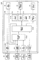
- FIG. 4 is a block diagram showing functions of the MC calculation section of the controller shown in FIG.
- FIG. 5 is an explanatory diagram showing the calculation method of the speed/posture predictor and the speed command calculator of the controller shown in FIG.
- the functions of the MC calculation unit 91 of the controller 80 are subdivided into an MC determination unit 911, an attitude calculation unit 912, a target plane calculation unit 913, an operation amount calculation unit 914, a speed/attitude prediction unit 915, a speed It has a command calculation section 916 , an actuator control section 917 and a hydraulic pump control section 918 .
- Each functional unit of the MC calculation unit 91 repeatedly executes various calculations shown below in each calculation period.
- the MC determination unit 911 determines whether MC is valid or invalid based on the instruction signal from the MC switching device 28 .
- the MC switching device 28 outputs the determination result of whether the MC is valid or invalid to the velocity/attitude prediction section 915 .
- the attitude calculation unit 912 calculates the attitude of the front work device 1 and the positions of the control points based on the detection signal from the attitude detection device 30 . For example, the three-dimensional coordinates of the attitude of the front work device 1 and the toe position of the bucket 13 in the local coordinate system are calculated. Since this calculation follows general geometrical relationships, detailed description is omitted.
- the posture of the front work device 1 and the position of the control point which are the calculation results of the posture calculation unit 912 , are output to the display control unit 92 and the speed/posture prediction unit 915 .
- the target plane calculation unit 913 calculates the position information of the target plane based on the information from the target plane setting device 101 .
- the position information of the target plane which is the calculation result, is output to the display control unit 92 and the speed/posture prediction unit 915 .
- the position information of the target plane may be stored in the storage device 81 .
- the operation amount calculation unit 914 calculates the operation amount of each of the operation devices 51 to 53 based on the detection signal from the operation amount detection device 78.
- a boom lowering operation amount is calculated from the detection value of the first pressure sensor 75a, and a boom raising operation amount is calculated from the detection value of the second pressure sensor 75b.
- the operation amount of the arm dump is calculated from the detection value of the third pressure sensor 76a, and the operation amount of the arm cloud is calculated from the detection value of the fourth pressure sensor 76b.
- the operation amount of the bucket dump is calculated from the detection value of the fifth pressure sensor 77a, and the operation amount of the bucket cloud is calculated from the detection value of the sixth pressure sensor 77b.
- the operation amount of each of the operating devices 51 to 53 which is the operation result of the operation amount calculation section 914, is output to the speed command calculation section 916.
- the speed/posture prediction unit 915 predicts the speed of each of the hydraulic actuators 15 to 17 of the front work device 1 at a future time after the lapse of a predetermined set time from the current time (current calculation cycle) at the time of calculation, In addition, the predicted value of the posture of the front working device 1 and the predicted value of the position of the control point with respect to the target plane are calculated. Specifically, for example, the posture of the front working device 1 and the position of the control point at the current time (current computation cycle), which is the calculation result of the posture calculation unit 912, and the position of the target plane, which is the calculation result of the target plane calculation unit 913.
- each of the above predicted values at a future time after a predetermined time has elapsed from the current time is calculated.
- a first time T1 is set that substantially coincides with the response delay time of the actual speed to the speed command of each of the hydraulic actuators 15-17.
- the calculation result (predicted value) of the speed/posture prediction unit 915 is output to the speed command calculation unit 916 .
- velocity/attitude prediction section 915 executes the calculation of the above-described predicted value when the decision result indicating that MC is valid is input from MC decision section 911 . It is configured not to execute the calculation of the predicted value when it is input. A detailed calculation method of the velocity/posture prediction unit 915 will be described later.
- the speed command calculation unit 916 determines that the control point of the front work device 1 will be at a future time after the set time has elapsed from the current time (current calculation cycle).
- Boom cylinder 15 boost 11
- arm cylinder 16 arm 12
- bucket cylinder 17 The speed of the bucket 13
- This calculation assumes that the control point of the front work device 1 (for example, the tip of the bucket 13) is already positioned near the target plane, and the control point of the front work device 1 enters below the target plane. This is for controlling the operation of the front working device 1 so that it moves along the target surface without any movement.
- this calculation is for controlling the operation of the boom cylinder 15 according to the operation of at least one of the arm cylinder 16 and the bucket cylinder 17 under the above conditions. That is, in the present embodiment, the boom cylinder 15 is targeted for forced operation or limited operation by MC.
- the speed command calculation unit 916 calculates the future time after the first time T1 from the current time (current calculation cycle). The target speeds of the arm cylinder 16 and the bucket cylinder 17 at the time of are calculated. In addition, the speed command calculation unit 916 calculates the predicted values of the speed of the hydraulic actuators 15 to 17, the predicted values of the attitude of the front working device 1, and the positions of the control points with respect to the target plane, which are the calculation results of the speed/posture prediction unit 915.
- the target speed of the boom cylinder 15 that satisfies the above conditions is calculated at a future time after the first time T1 has elapsed from the current time (current calculation cycle).
- the speed command calculation unit 916 outputs the calculated target speeds of the hydraulic actuators 15 to 17 to the actuator control unit 917 and the hydraulic pump control unit 918 as speed commands at the current time (current calculation cycle). Details of this calculation method of the speed command calculation unit 916 will be described later.
- the speed command calculation unit 916 determines each hydraulic actuator based on the operation amount of the operation devices 51 to 53, which is the detection result of the operation amount detection device 78. 15 to 17 target speeds are calculated. That is, the operations of the hydraulic actuators 15 to 17 are controlled according to the operation of the operation devices 51 to 53 by the operator, and the forced operation and the limited operation of the boom cylinder 15 not depending on the operation of the operation device 51 by the operator are not executed.
- the actuator control section 917 performs calculations for controlling the hydraulic actuators 15-17. Specifically, based on the speed commands for the hydraulic actuators 15 to 17, which are the calculation results of the speed command calculator 916, target pilot pressures for the flow control valves 45 to 47 corresponding to the hydraulic actuators 15 to 17 are calculated.
- the actuator control unit 917 includes a boom control unit 917a that controls the first flow control valve 45 corresponding to the boom cylinder 15, an arm control unit 917b that controls the second flow control valve 46 corresponding to the arm cylinder 16, A bucket control section 917 c that controls the third flow control valve 47 corresponding to the bucket cylinder 17 .
- the boom control unit 917a calculates the target pilot pressure of the first flow control valve 45 based on the speed command of the boom cylinder 15, which is the calculation result of the speed command calculation unit 916, and uses the target pilot pressure of the calculation result as the first flow rate. It is output to the electromagnetic proportional valve control section 93 as a pilot pressure command for the control valve 45 .
- the arm control unit 917b calculates the target pilot pressure of the second flow control valve 46 based on the speed command of the arm cylinder 16, which is the calculation result of the speed command calculation unit 916, and uses the target pilot pressure of the calculation result as the second flow rate. It is output to the electromagnetic proportional valve control section 93 as a pilot pressure command for the control valve 46 .
- the bucket control unit 917c calculates the target pilot pressure of the third flow control valve 47 based on the speed command of the bucket cylinder 17, which is the calculation result of the speed command calculation unit 916, and uses the target pilot pressure of the calculation result as the third flow rate. It is output to the electromagnetic proportional valve control section 93 as a pilot pressure command for the control valve 47 .
- the hydraulic pump control unit 918 performs calculations for controlling the pump volume of the hydraulic pump 42 . Specifically, the target pump displacement of the hydraulic pump 42 is calculated based on the speed commands of the plurality of hydraulic actuators 15 to 17, which are the calculation results of the speed command calculator 916. FIG. The calculated target pump displacement of the hydraulic pump 42 is output to the regulator control unit 94 as a pump displacement command.
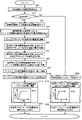
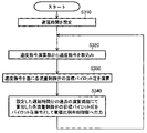
- FIG. 5 is a flow chart showing an example of a calculation processing procedure in a speed/attitude predictor and a speed command calculator of the controller shown in FIG.
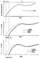
- FIG. 6 is an explanatory diagram showing the calculation method of the speed/posture predictor and the speed command calculator of the controller shown in FIG. Note that the flowchart shown in FIG. 5 shows calculation processing for one calculation cycle.
- the upper diagram shows the information about the speed of the arm cylinder
- the lower diagram shows the information about the speed of the boom cylinder.
- the solid line indicates the actual speed of the hydraulic actuator
- the dashed line indicates the speed command of the hydraulic actuator
- the one-dot chain line indicates the predicted speed of the hydraulic actuator.
- step S20 The velocity/attitude prediction unit 915 in the MC calculation unit 91 shown in FIG. or invalid), it is determined whether or not to execute MC (step S20 shown in FIG. 5).
- the determination result of the MC determining unit 911 is valid (ON)
- step S20 when it determines with YES, while progressing to step S30, when determining with NO, it progresses to step S200.
- step S20 If the determination in step S20 is YES, the velocity/posture prediction unit 915 takes in the position information of the target plane calculated by the target plane calculation unit 913 based on the information from the target plane setting device 101 (the step shown in FIG. 5). S30).
- the attitude calculation unit 912 takes in the information about the attitude of the front working device 1 calculated based on the detection signal of the attitude detection device 30 and the position of the control point (for example, the toe of the bucket 13) (step S40 shown in FIG. 5). ). Based on this fetched information, the actual velocities of the hydraulic actuators 15 to 17 at the current time (current calculation cycle) are calculated (step S50 shown in FIG. 5). Specifically, the attitude of each hydraulic actuator (boom cylinder 15, arm cylinder 16, bucket cylinder 17) captured in the current calculation cycle and each hydraulic actuator 15 to 17 captured in the calculation cycle one cycle before the current calculation cycle. The current speed (actual speed) of each of the hydraulic actuators 15 to 17 is calculated from the difference from the posture of . This calculation corresponds to the black dot at the current time (current calculation cycle) in the upper diagram of FIG. However, FIG. 6 shows only the case of the arm cylinder 16 .
- the velocity/posture prediction unit 915 calculates the respective hydraulic actuators from the current time (current calculation cycle) to a future time after the first time T1 has elapsed (hereinafter sometimes referred to as a first future time).
- the history of predicted values of speeds 15 to 17 is calculated (step S60 shown in FIG. 5). Specifically, during the period from the past time (hereinafter sometimes referred to as first past time) that is a first time T1 before the current time (current calculation cycle) to the current time (current calculation cycle)
- the past history of the speed commands of the hydraulic actuators 15 to 17 calculated and output by the speed command calculation unit 916 is compared with the current speed (actual speed) of the hydraulic actuators 15 to 17 calculated in step S50.
- the speed commands for the hydraulic actuators 15 to 17 output by the speed command calculation unit 916 at the first past time are matched with the speeds (actual speeds) of the hydraulic actuators 15 to 17 at the current time calculated in step S50.
- the history of the speed commands for the hydraulic actuators 15 to 17 in the shifted past calculation cycles is regarded as the history of predicted values of the speeds of the hydraulic actuators 15 to 17 from the current time to the first future time. That is, with the speed (actual speed) of each hydraulic actuator 15 to 17 at the present time as a reference, the speed of each hydraulic actuator 15 to 17 output from the speed command calculation unit 916 from the first past time to the present time.
- the future history of the speed of each of the hydraulic actuators 15 to 17 in the time interval from the current time to the first future time is predicted. This is because the speed command for each hydraulic actuator 15-17 is achieved as the actual speed of each hydraulic actuator 15-17 with a response delay of the first time T1.
- the velocity/posture prediction unit 915 predicts the expansion/contraction length of each of the hydraulic actuators 15 to 17 between the current time and the first future time (step S70 shown in FIG. 5). Specifically, the history of the predicted values of the velocities of the hydraulic actuators 15 to 17 from the current time calculated in step S60 to the first future time is calculated in the time interval from the current time to the first future time. By integrating by , the prediction of the expansion/contraction length of each of the hydraulic actuators 15 to 17 occurring from the current time to the first future time is calculated.
- the speed/posture prediction unit 915 predicts the posture of the front working device 1 and the position of the control point with respect to the target plane at the first future time (step S80 shown in FIG. 5). Specifically, the position of the front working device 1 at the current time (postures of the boom 11, the arm 12, and the bucket 13) and the position of the control point (for example, the toe of the bucket 13) captured in step S40 are stored in step S70. Attitude and control of the front working device 1 at the first future time based on the calculated predicted value of the expansion/contraction length of each hydraulic actuator 15 to 17 at the first future time and the position information of the target plane captured in step S30. Compute the position of the point relative to the target surface (eg, the distance from the control point to the target surface).
- the velocity/attitude prediction unit 915 calculates the attitude of the front work device 1 and the position of the control point with respect to the target plane at the first future time, which is the calculation result of step S80, and the respective positions at the first future time, which are the calculation result of step S60.
- the predicted values of the velocities of the hydraulic actuators 15 to 17 are output to the velocity command calculator 916 .
- the speed command calculator 916 calculates the target speed of the boom cylinder 15 required to satisfy the above conditions at the first future time (step S90 shown in FIG. 5). Specifically, the predicted value of the attitude of the front work device 1 and the predicted value of the position of the control point with respect to the target plane at the first future time calculated in step S80, and the Based on the predicted speed values of the hydraulic actuators 15 to 17, the speed of the boom cylinder 15 that enables the control point of the front work device 1 to be positioned on the target plane at the first future time is determined at the first future time. Calculate as the target speed.
- this calculation is performed according to the operation of at least one of the arm cylinder 16 and the bucket cylinder 17 by the operation of the operating devices 52 and 53, and the operation of the boom cylinder 15 by activating the MC not depending on the operation of the operating device 51. This is the part that calculates the command for the forced operation of
- the speed command calculation unit 916 takes in the pilot pressure (first operation signal) as the operation amount of the second operation device 52 for the arm cylinder 16, which is the operation result of the operation amount calculation unit 914 (shown in FIG. 5).
- Step S100) the target speed of the arm cylinder 16 at the first future time is calculated based on the captured pilot pressure (step S110 shown in FIG. 5).
- the target speed of the arm cylinder 16 is calculated, for example, with reference to a preset characteristic diagram 916a shown in FIG. In the characteristic diagram 916a shown in FIG.
- the target speed of the arm cylinder 16 is 0 within a certain range (dead zone) including the pilot pressure (first operation signal) of the second operating device 52, and the pilot pressure exceeds the dead band, it increases in proportion to the increase in the pilot pressure, and after that, when the pilot pressure exceeds a certain value, it is set to a constant value.
- the MC controls the operation of the boom cylinder 15 when the second operating device 52 for the arm cylinder 16 is operated by the operator. Therefore, the operation amount of the third operating device 53 for the bucket cylinder 17 is 0, so the description of the calculation of the target speed of the bucket cylinder 17 is omitted.
- the third operating device 53 for the bucket cylinder 17 is also operated, similarly to the case of the arm cylinder 16, the pilot pressure (first operation signal) as the operation amount of the third operating device 53 is taken in (step S100 shown in FIG. 5), and the target speed of the bucket cylinder 17 at the first future time is calculated based on the taken-in pilot pressure (step S110 shown in FIG. 5).
- the speed command calculation unit 916 outputs the target speed of the boom cylinder 15 at the first future time calculated in step S90 as the speed command of the boom cylinder 15 at the current time (current calculation cycle), and outputs the speed command at step S110.
- the target speed of the arm cylinder 16 at the first future time calculated in step S120 shown in FIG. 5 is output as the speed command of the arm cylinder 16 at the present time (current calculation period).
- the relationship between the target speed of the boom cylinder 15 and the speed command in step S120 is represented by the outline arrow from the black point of III (target speed at future time) to the black point of IV (output as speed command at present time) shown in FIG. equivalent to part.
- step S120 the target speed of the bucket cylinder 17 at the first future time is set to the current time (current calculation period) as a speed command (step S120 shown in FIG. 5).
- a speed command for each hydraulic actuator 15 to 17 is output to an actuator control section 917 and a hydraulic pump control section 918 .
- the speed command calculation unit 916 calculates each pilot pressure as the operation amount of each operation device 51 to 53 corresponding to each hydraulic actuator 15 to 17, which is the calculation result of the operation amount calculation unit 914. (step S200 shown in FIG. 5), and calculates the target speed of each hydraulic actuator 15-17 at the first future time based on the pilot pressure of each operating device 51-53 (step S210 shown in FIG. 5). .
- the target speeds of the hydraulic actuators 15 to 17 are calculated, for example, with reference to a preset characteristic diagram 916b shown in FIG. A characteristic diagram 916b shown in FIG. 5 is set similarly to the characteristic diagram 916a.
- the velocity/posture prediction unit 915 does not predict the posture of the front work device 1 , the position of the control point with respect to the target plane, and the velocities of the hydraulic actuators 15 to 17 of the front work device 1 . That is, the speed command calculation unit 916 calculates the target speed of the boom cylinder 15 corresponding to the boom raising pilot pressure or the boom lowering pilot pressure, and calculates the target speed of the arm cylinder 16 corresponding to the arm cloud pilot pressure or the arm dump pilot pressure. Then, the target speed of the bucket cylinder 17 corresponding to the bucket cloud pilot pressure or the bucket dump pilot pressure is calculated.
- the speed command calculation unit 916 finally uses the target speed at the first future time for each hydraulic actuator 15 to 17 calculated in step S210 as the speed command at the current time (current calculation cycle) for each hydraulic actuator 15 to 17. It is output to the actuator control section 917 and the hydraulic pump control section 918 (step S220 shown in FIG. 5). That is, the MC calculation unit 91 calculates a speed command for commanding the operation of each of the hydraulic actuators 15-17 according to the operation of the operating devices 51-53.
- step S220 ends, the current calculation cycle ends, and the process returns to the start to start the next calculation cycle.
- FIG. 7 is an explanatory diagram showing the relationship between the target speed, the speed command, and the actual speed of each hydraulic actuator during execution of MC with respect to arm crowding operation in the first embodiment of the working machine of the present invention.
- the upper diagram shows the time history of the operation amount of the second operating device for operating the arm
- the middle diagram shows the time history of the target speed, speed command, and actual speed of the arm cylinder
- the lower diagram shows the target of the boom cylinder. It shows the time history of speed, speed command, and actual speed.
- the first period S1 is a period during which the operator does not operate the second operation device 52.
- the second period S2 is a period during which the second operating device 52 is being operated, but the arm cylinder is not being operated due to the influence of the delay in response to the operation of the second operating device 52 .
- the third period S3 is a period during which the arm cylinder is operated by operating the second operating device 52 .
- the controller 80 determines YES in step S20 of the flowchart shown in FIG. 5, and executes the processes of steps S30 to S120.
- the second operation device 52 is not operated during the first period S1. Therefore, the speed (actual speed) of each of the hydraulic actuators 15 to 17 at the current time, which is the calculation result of the speed/posture prediction unit 915, is 0 (step S50 shown in FIG. 5), and the first future time (from the current time The history of the predicted values of the velocities of the hydraulic actuators 15 to 17 at the future time after the lapse of the first time T1 is also 0 (step S60 shown in FIG. 5). From these calculation results of the speed/posture prediction unit 915, the predicted value (calculation result) of the expansion/contraction length of each of the hydraulic actuators 15 to 17 at the first future time becomes 0 (step S70 shown in FIG.
- step S80 the target speeds of the arm cylinder 16 and the boom cylinder 15, which are the calculation results of the speed command calculator 916, are 0 (steps S90 to S110 shown in FIG. 5). Therefore, in the first period S1, the speed command calculator 916 outputs the target speed 0 as the speed command at the current time.
- the speed command calculation unit 916 outputs the detection signal of the operation amount detection device 78 (fourth pressure sensor 76b shown in FIG. 2). based on the arm cloud pilot pressure corresponding to the arm cylinder 16 at the first future time (steps S100 to S110 shown in FIG. 5), and the target speed of the calculation result at the current time (current calculation cycle) It is output as a speed command for the arm cylinder 16 (step S120 shown in FIG. 5). That is, in the second period S2, a speed command for the arm cylinder 16 according to the arm cloud operation of the second operating device 52 is output.
- the operation of the arm cylinder 16 has not started due to the effect of the response delay of the actual speed to the speed command of the arm cylinder 16 .
- the third operation device 53 for operating the bucket is not operated, so the target speed and speed command of the bucket cylinder 17 at the first future time are always zero.
- the speed (actual speed) of each of the hydraulic actuators 15 to 17 at the current time which is the calculation result of the speed/attitude prediction unit 915, is 0 (step shown in FIG. 5). S50).
- the past history of the speed command of the arm cylinder 16 output by the speed command calculation unit 916 from the first past time (past time that is the first time T1 before the current time) to the current time is as follows: As described above, since it is not 0 in the second period S2, based on the past history of the speed command of the arm cylinder 16, the predicted value of the speed of the arm cylinder 16 from the current time to the first future time. A history is calculated (step S60 shown in FIG. 5).
- step S70 the predicted value of the expansion/contraction length of each of the hydraulic actuators 15 to 17 at the first future time is calculated (step S70 shown in FIG. 5), and the front working device at the first future time is calculated.
- a predicted value of the attitude of 1 and the position of the control point with respect to the target plane is calculated (step S80 shown in FIG. 5).
- the speed command calculation unit 916 calculates the target speed of the boom cylinder 15 at the first future time that satisfies a predetermined condition (step S90 shown in FIG. 5).
- the calculated target speed of the boom cylinder 15 at the first future time is output as the speed command at the current time (current calculation cycle) (step S120 shown in FIG. 5). That is, even if the first operation device 51 for operating the boom is not operated, a command for forced operation of the boom cylinder 15 that satisfies a predetermined condition is generated.
- the history of the speed command for the boom cylinder 15 output from the speed command calculation unit 916 during the second period S2 includes the predicted value of the speed of the boom cylinder 15 at the first future time, and the predicted value of the telescopic length of the boom cylinder 15. , are used to calculate the predicted values of the attitude of the front working device 1 and the positions of the control points with respect to the target plane.
- the arm cylinder 16 does not start operating due to the effect of the delay in response to the arm crowding operation of the second operating device 52.
- the first future time after the first time T1 has elapsed from the calculation period.
- the arm-crowd operation of the second operation device 52 is continued, and the response delay time (approximately the first time T1) has passed since the start of the arm-crowd operation. For this reason, the arm cylinder 16 operates according to the arm cloud operation with the response delay time.
- the speed command calculation unit 916 calculates the target speed of the arm cylinder 16 at the first future time according to the arm cloud operation, and sets the target speed of the calculation result to the current time. It is output as a speed command for the arm cylinder 16 in (the current calculation cycle) (steps S100 to 120 shown in FIG. 5).
- the speed/posture prediction unit 915 estimates the speed (not 0) of each of the hydraulic actuators 15 to 17 at the current time. Calculate (step S50 shown in FIG. 5). Furthermore, based on the past history of the speed of each hydraulic actuator 15 to 17 at the current time of the calculation result and the speed command of each hydraulic actuator 15 to 17 output by the speed command calculation unit 916, each hydraulic actuator 15 to 17 (step S60 shown in FIG. 5). From these calculation results of the speed/posture prediction unit 915, the predicted value of the expansion/contraction length of each of the hydraulic actuators 15 to 17 at the first future time is calculated (step S70 shown in FIG.
- step S80 the prediction calculation of the speed/attitude prediction unit 915 includes the influence of the actual operation (actual speed) of the hydraulic actuators 15-17.
- the speed command calculation unit 916 calculates the target speed of the boom cylinder 15 at the first future time that satisfies a predetermined condition based on each predicted value (calculation result) of the speed/posture prediction unit 915. is calculated (step S90 shown in FIG. 5), and the calculated target speed of the boom cylinder 15 at the first future time is output as a speed command at the current time (current calculation cycle) (step S120 shown in FIG. 5).
- a forced operation command for the boom cylinder 15 is generated including the effects of the actual operations (actual speeds) of the hydraulic actuators 15-17.
- the first future time By predicting the operation of each of the hydraulic actuators 15 to 17, the speed command of the boom cylinder 15 at the current time (current calculation cycle) considering the response delay of the actual speed with respect to the speed command of each hydraulic actuator 15 to 17 is output. It is possible. That is, when the second operating device 52 is operated and the arm cylinder 16 is actually operating, by outputting in advance a speed command for the boom cylinder 15 corresponding to the predicted operation of the arm cylinder 16, each hydraulic actuator 15 It is possible to realize the execution of MC considering the response delay of ⁇ 17.
- the operation of each hydraulic cylinder 15 to 17 at the first future time is predicted.
- the hydraulic excavator (working machine) includes a front working device 1 (working device) that performs work and a boom cylinder that drives the front working device 1 (working device).
- a front working device 1 working device
- a boom cylinder that drives the front working device 1 (working device).
- an arm cylinder 16 an arm cylinder 16
- a bucket cylinder 17 plural of hydraulic actuators
- a hydraulic pump 42 that supplies pressure oil to the boom cylinder 15, the arm cylinder 16, and the bucket cylinder 17 (plurality of hydraulic actuators)
- a boom from the hydraulic pump 42 A first flow control valve 45, a second flow control valve 46, a third flow control valve 47 (plurality of control valves), posture detection device 30 for detecting the posture of front work device 1 (work device), boom cylinder 15, arm cylinder 16, and bucket cylinder 17 (plurality of hydraulic actuators).
- Each speed command is calculated for each calculation cycle, and boom cylinder 15, arm cylinder 16, and bucket cylinder 17 are calculated based on the calculated speed commands of boom cylinder 15, arm cylinder 16, and bucket cylinder 17 (plurality of hydraulic actuators). and a controller 80 that outputs a control signal for controlling each of the (plurality of hydraulic actuators).
- the controller 80 operates the boom cylinder 15 (first hydraulic actuator) according to the operation of the arm cylinder 16 (second hydraulic actuator) under predetermined conditions.
- the actual speed of each of the plurality of hydraulic actuators in the current calculation cycle is calculated based on the detection signal of the posture detection device 30, and the actual speed of each of the plurality of hydraulic actuators 15, 16, 17 and
- the boom cylinder 15 (first hydraulic A control signal for controlling the boom cylinder 15 (first hydraulic actuator) is calculated based on the calculated speed command of the boom cylinder 15 (first hydraulic actuator) in the current calculation cycle. Output.
- the actual velocities of the hydraulic actuators 15, 16, and 17 calculated based on the detection signals of the posture detection device 30, and the respective hydraulic pressures calculated in the previous calculation period than the current calculation period.
- the past history of speed commands for the actuators 15, 16 and 17 is used to calculate the speed command for the boom cylinder 15 (first hydraulic actuator) in the current calculation cycle that satisfies a predetermined condition.
- a speed command for the boom cylinder 15 (first hydraulic actuator) can be calculated in consideration of the response delay. Therefore, it is possible to reduce the influence of the response delay of the actual speed to the speed command of the hydraulic actuators 15, 16, 17 and improve the operation accuracy of the front work device 1 (work device) in MC.
- the controller 80 controls the actual speed of each of the plurality of hydraulic actuators 15, 16, and 17 based on the detection signal of the posture detection device 30 and the actual speed of each of the plurality of hydraulic actuators 15, 16, and 17 in the current calculation period, and the speed of each of the hydraulic actuators 15, 16, and 17 based on the detection signal of the posture detection device 30, and Elapsed first time T1 from the current calculation cycle using the past history of speed commands for each of the plurality of hydraulic actuators 15, 16, and 17 calculated from the calculation cycle T1 past to the current calculation cycle.
- a predicted value is calculated, and the control point of the front work device 1 (work device) is set after the first time T1 has elapsed from the current calculation cycle based on the predicted speed value, predicted attitude value, and predicted position value of the calculation results.
- a target speed of the first hydraulic actuator to be positioned on the target surface is calculated as a speed command for the current calculation cycle of the boom cylinder 15 (first hydraulic actuator), and the boom cylinder 15 (first hydraulic actuator ) to output a control signal for controlling the boom cylinder 15 (first hydraulic actuator) based on the speed command of the current calculation cycle.
- the past history of the speed commands of the hydraulic actuators 15, 16, and 17 calculated during the first time T1 from the current calculation cycle to the current calculation cycle is used. Since various prediction values are calculated after the first time T1 has elapsed from the current calculation cycle, the first time T1 is approximately equal to the response delay time of the actual speed to the speed command of each of the hydraulic actuators 15, 16, and 17. , various prediction values can be obtained in consideration of the response delay of the actual speed with respect to the speed command. Furthermore, based on various prediction values that take into consideration the response delay of the actual speed to the speed command, the control point of the front work device 1 (work device) will be positioned on the target plane after the first time T1 has elapsed from the current calculation cycle.
- the boom cylinder 15 Since the target speed of the boom cylinder 15 (first hydraulic actuator) is calculated as the speed command in the current calculation cycle, the boom cylinder 15 (first hydraulic actuator) that satisfies the predetermined conditions while considering the response delay of the actual speed with respect to the speed command is calculated. A velocity command for the first hydraulic actuator) can be obtained. For these reasons, it is possible to reduce the influence of the response delay of the actual speed with respect to the speed command of each hydraulic actuator 15, 16, 17 in the MC. It becomes possible to move the control point of the work device 1 (work device) along the target surface.
- FIG. 8 is a block diagram showing the functions of the MC calculation section of the controller forming part of the second embodiment of the working machine of the present invention.
- 9 is a flow chart showing an example of a calculation processing procedure in a speed/posture predictor and a speed command calculator of the controller shown in FIG. 8.
- FIG. 10A and 10B are explanatory diagrams showing calculation methods of the speed/posture prediction section and the speed command calculation section of the controller shown in FIG. FIG.
- FIG. 11 is an explanatory diagram showing the relationship between the target speed, speed command, and actual speed of each hydraulic actuator during execution of MC with respect to arm crowding operation in the second embodiment of the working machine of the present invention.
- 8 to 11 parts having the same reference numerals as those shown in FIGS. 1 to 7 are the same parts, and detailed description thereof will be omitted.
- the second embodiment of the working machine of the present invention shown in FIG. 8 differs from the first embodiment in that a speed/attitude predictor 915A and a speed command calculator 915A in the MC calculator 91A of the controller 80A 916A has a different calculation method.
- the speed/posture prediction unit 915 and the speed command calculation unit 916 in the MC calculation unit 91 of the controller 80 according to the first embodiment are configured such that the response delay time of the actual speed with respect to the speed command of each of the hydraulic actuators 15 to 17 is approximately 100%. The calculation is performed on the assumption that the time is T1 for one hour.
- the speed/attitude prediction unit 915A and the speed command calculation unit 916A according to the present embodiment set the response delay time of the actual speed to the speed command of the boom cylinder 15 to be approximately the second time T2 and the arm cylinder 16 Calculation is performed on the premise that the response delay time of the actual speed with respect to the speed command is approximately the third time T3.
- this embodiment is applied only when the third time T3 is longer than the second time T2.
- the speed/posture prediction unit 915A of the present embodiment predicts the front working device at a future time (hereinafter sometimes referred to as a second future time) after the second time T2 has elapsed from the current time (current calculation cycle). 1, a predicted value of the attitude of the front working device 1, and a predicted value of the position of the control point with respect to the target plane.
- the posture of the front working device 1 and the position of the control point at the current time which is the calculation result of the posture calculation unit 912
- the position information of the target plane which is the calculation result of the target plane calculation unit 913
- the speed command calculation is performed during the past time (hereinafter sometimes referred to as second past time) that is a second time T2 before the current time (current calculation cycle) to the current time (current calculation cycle).
- a detailed calculation method of the speed/posture prediction unit 915A will be described later.
- the speed command calculation unit 916A controls the front work device 1 at a second future time after the second time T2 has elapsed from the current time (current calculation cycle).
- the speed of the boom cylinder 15 (boom 11) required at the second future time is calculated as the target speed so that the point (for example, the tip of the bucket 13) is positioned on the target plane.
- the speed command calculation unit 916A calculates the predicted values of the speeds of the hydraulic actuators 15 to 17, the predicted values of the posture of the front work device 1, and the target surface of the control point, which are the calculation results of the speed/attitude prediction unit 915A.
- a target velocity of the boom cylinder 15 that satisfies the above condition at the second future time is calculated based on the predicted value of the position with respect to .
- the target speeds of the arm cylinder 16 and the bucket cylinder 17 at the third future time are calculated.
- the speed command calculation unit 916A outputs the target speed of each of the hydraulic actuators 15 to 17, which is the calculation result, as a speed command at the current time (current calculation cycle).
- FIG. 9 The flowchart shown in FIG. 9 is for one calculation cycle.
- the upper diagram shows the information about the speed of the arm cylinder
- the lower diagram shows the information about the speed of the boom cylinder.
- the solid line indicates the actual speed of the hydraulic actuator
- the dashed line indicates the speed command of the hydraulic actuator
- the one-dot chain line indicates the predicted speed of the hydraulic actuator.
- the velocity/posture prediction unit 915A shown in FIG. 8 determines execution of MC based on the determination result (valid or invalid) of the MC determination unit 911 (see FIG. 9), as in the first embodiment. Steps S10 to S20 of the flowchart shown). If the determination in step S20 is YES, steps S30 to S120 including steps S60A to S90A are executed, while if the determination in step S20 is NO, steps similar to those in the first embodiment The processing from S200 to step S220 is executed.
- step S20 the velocity/posture prediction unit 915A acquires the position information of the target plane from the target plane calculation unit 913 (step S30 shown in FIG. 9), as in the first embodiment. . Furthermore, the posture of the front work device 1 at the current time and the positions of the control points are taken in from the posture calculation unit 912, and the actual speeds of the hydraulic actuators 15 to 17 at the current time (the current calculation cycle) are calculated based on the taken information. (Steps S40 to S50 shown in FIG. 9). The calculation of the actual speed corresponds to the black dot at the current time (current calculation cycle) in the upper diagram of FIG. However, FIG. 10 only shows the case of the arm cylinder 16 .
- the velocity/posture prediction unit 915A predicts the velocity of each of the hydraulic actuators 15 to 17 from the current time (current calculation cycle) to the future time after the second time T2 (second future time).
- a value history is calculated (step S60A shown in FIG. 9). Specifically, from the time (third past time) that is the third time T3 minutes past the current time (current calculation cycle) to the past current time (past calculation cycle) that is the second time T2 minutes past.
- the past history of the speed command of the arm cylinder 16 calculated and output by the speed command calculation unit 916A is transferred to the current speed (actual speed) of the arm cylinder 16 calculated in step S50.
- the speed command for the arm cylinder 16 output by the speed command calculation unit 916A at the third past time is matched with the current speed (actual speed) of the arm cylinder 16 calculated in step S50.
- the past history of the transferred speed command for the arm cylinder 16 is regarded as the history of predicted values of the speed of the arm cylinder 16 from the current time to the second future time. That is, with reference to the speed (actual speed) of the arm cylinder 16 at the current time, the arm speed output from the speed command calculation unit 916A from the third past time to the past time after the second time T2 has elapsed. Based on the past history of speed commands for the cylinder 16, the future history of the speed of the arm cylinder 16 in the time interval from the current time to the second future time is predicted.
- This calculation corresponds to I (transition) shown in FIG. That is, in the upper diagram of FIG. 10, the dashed line (the speed command) is shifted so that the black dot of the speed command at the third past time (t0-T3) coincides with the black dot of the actual speed at the current time (t0), from the current time (t0) to the second future time ( t0+T2) (predicted values of the speed of each hydraulic actuator 15 to 17) is generated.
- the calculation of the history of the predicted value of the speed of the boom cylinder 15 is similar to the calculation method in the case of the first embodiment, and the set time is changed from the first time T1 to the second time T2. is. That is, based on the speed (actual speed) of the boom cylinder 15 at the present time, the current time (current calculation cycle) is calculated from the past time (second past time) that is a second time T2 before the current time (current calculation cycle). Future speed of the boom cylinder 15 in the time interval from the current time to the second future time based on the past history of the speed command of the boom cylinder 15 output from the speed command calculation unit 916A until It predicts the history of Referring to FIG. 6 used in the description of the first embodiment, the first time T1 in FIG.
- the velocity/posture prediction unit 915A predicts the expansion/contraction length of each of the hydraulic actuators 15 to 17 between the current time and the second future time (step S70A shown in FIG. 9). Specifically, the history of the predicted values of the velocities of the hydraulic actuators 15 to 17 from the current time to the second future time calculated in step S60A is calculated in the time interval from the current time to the second future time. By integrating by , the expansion/contraction length of each of the hydraulic actuators 15 to 17 occurring from the current time to the second future time is predicted.
- the speed/attitude prediction unit 915A predicts the attitude of the front working device 1 and the position of the control point with respect to the target plane at the second future time (step S80A shown in FIG. 9). Specifically, the attitude of the front working device 1 at the current time (the attitudes of the boom 11, the arm 12, and the bucket 13) and the position of the control point captured in step S40, and the positions of the control points at the second future time calculated in step S70A. Based on the predicted extension/contraction lengths of the hydraulic actuators 15 to 17 and the positional information of the target plane acquired in step S30, the attitude of the front work device 1 and the position of the control point with respect to the target plane at the second future time (for example, , the distance from the control point to the target surface).
- the velocity/attitude prediction unit 915A calculates the attitude of the front work device 1 and the positions of the control points with respect to the target plane at the second future time, which are the calculation results of step S80A, and the respective positions at the second future time, which are the calculation results of step S60A.
- the predicted values of the velocities of the hydraulic actuators 15 to 17 are output to the velocity command calculator 916A.
- the speed command calculation unit 916A calculates the target speed of the boom cylinder 15 required to satisfy a predetermined condition at the second future time (step S90A shown in FIG. 9). Specifically, the predicted value of the attitude of the front work device 1 and the predicted value of the position of the control point with respect to the target plane at the second future time calculated in step S80A, and the Based on the predicted speed values of the hydraulic actuators 15 to 17, the speed of the boom cylinder 15 that enables the control point of the front work device 1 to be positioned on the target plane at the second future time is determined at the second future time. Calculate as the target speed.
- this calculation is performed according to the operation of at least one of the arm cylinder 16 and the bucket cylinder 17 by operating the operating devices 52 and 53, and the boom cylinder 15 by activating MC not depending on the operation of the operating device 51. This is the part that calculates the command for the forced operation of
- the speed command calculation unit 916A acquires the pilot pressure as the operation amount of the second operating device 52 from the operation amount calculation unit 914, as in the case of the first embodiment (step S100 shown in FIG. 9). , the target speed of the arm cylinder 16 at the third future time is calculated based on the captured pilot pressure (step S110 shown in FIG. 9). When the third operating device 53 is also operated, the target speed of the bucket cylinder 17 at the third future time is also calculated.
- the speed command calculation unit 916A outputs the target speed of the boom cylinder 15 at the second future time calculated in step S90A as the speed command of the boom cylinder 15 at the current time (current calculation cycle), and outputs the speed command at step S110.
- the target speed of the arm cylinder 16 calculated in step S120 shown in FIG. 9 is output as the speed command of the arm cylinder 16 at the present time.
- the relationship between the target speed of the boom cylinder 15 and the speed command in this step S120 is represented by the white arrow from the black point of III (target speed at future time) to the black point of IV (output as speed command at present time) shown in FIG. equivalent to part.
- step S120 ends, the current calculation cycle ends, and the process returns to the start to start the next calculation cycle.
- FIG. 11 the upper diagram shows the time history of the operation amount of the second operating device for operating the arm
- the middle diagram shows the time history of the target speed, speed command, and actual speed of the arm cylinder
- the lower diagram shows the target of the boom cylinder. It shows the time history of speed, speed command, and actual speed.
- a first period S1 is a period during which the operator does not operate the second operating device 52.
- the second period S2 is a period during which the second operating device 52 is being operated, but the arm cylinder is not being operated due to the influence of the delay in response to the operation of the second operating device 52 .
- the arm This is the period in which the speed command for the boom cylinder 15 is 0 even if the speed command (value other than 0) for the cylinder 16 is output.
- the period S2(b) of the second period S2 is a period during which the speed command (value other than 0) for the boom cylinder 15 is output according to the output of the speed command for the arm cylinder 16 .
- a third period S ⁇ b>3 is a period during which the arm cylinder 16 is operated by operating the second operating device 52 . Since the first period S1 is the same as in the first embodiment, the description thereof is omitted.
- the speed command calculation unit 916A calculates the target speed of the arm cylinder 16 after the third time T3 has elapsed based on the arm cloud pilot pressure corresponding to the detection signal of the operation amount detection device 78 (step shown in FIG. 9). S100-S110).
- the speed/attitude prediction unit 915A predicts the attitude and control point of the front work device 1 at the second future time with respect to the target plane based on the past history of the speed commands of the hydraulic actuators 15 to 17 output in the past.
- a predicted value of the position and a predicted value of the velocity of each of the hydraulic actuators 15 to 17 are calculated (steps S60A to S80A shown in FIG. 9). Based on each predicted value that is the calculation result of the speed/posture prediction unit 915A, the speed command calculation unit 916A calculates the target speed of the boom cylinder 15 at the second future time that satisfies a predetermined condition (steps shown in FIG. 9). S90A).
- the second time T2 substantially matching the response delay time of the boom cylinder 15 is shorter than the third time T3 substantially matching the response delay time of the arm cylinder 16, so the second period During the period S2(a) corresponding to the difference between the third time T3 and the second time T2 of S2, the calculation result of the target speed of the boom cylinder 15 at the second future time after the second time T2 has elapsed is 0. Clearly.
- the speed command calculation unit 916A sets the target speed (value of 0) of the boom cylinder 15 after the lapse of the second time T2 (second future time) as the speed command of the boom cylinder 15 to be output at the current time.
- a target speed (a value corresponding to the amount of operation of the operating device 52) after the lapse of the third time T3 is output to the actuator control section 917 as a speed command for the boom cylinder 15.
- FIG. Therefore, as shown in FIG. 11, in period S2(a), the speed command for the arm cylinder 16 is output according to the operation of the operating device 52, while the speed command for the boom cylinder 15 is zero.
- the speed command calculation unit 916A calculates the second future time after the second time T2, which is the calculation result of the speed/attitude prediction unit 915A, as in the period S2(a).
- the target speed of the boom cylinder 15 at a second future time after the lapse of the second time T2 that satisfies a predetermined condition is calculated (step S90A shown in FIG. 9).
- a non-zero value is calculated as the target speed.
- the speed command calculation unit 916A sets the target speed (value other than 0) of the boom cylinder 15 after the lapse of the second time T2 (second future time) as the speed command of the boom cylinder 15 to be output at the current time.
- a target speed (a value corresponding to the amount of operation of the operating device 52) after the lapse of the third time T3 is output as a speed command for the boom cylinder 15.
- FIG. Therefore, as shown in FIG. 11, in the period S2(b), the speed command for the arm cylinder 16 is output according to the operation of the operating device 52, and the speed command for the boom cylinder 15 is delayed by its own response delay time ( The second time T2) and the response delay time (third time T3) with respect to the speed command of the arm cylinder 16 are considered.
- the arm cylinder 16 and the boom cylinder 15 operate according to the output of the speed command.
- the speed command calculation unit 916A calculates each predicted value of the second future time after the second time T2, which is the calculation result of the speed/posture prediction unit 915A considering the speed of each of the hydraulic actuators 15 to 17 at the current time.
- the target speed of the boom cylinder 15 at a second future time after the second time T2 has elapsed is calculated (step S90A shown in FIG. 9). Therefore, in the third period S3, as in the case of period S2(b), as shown in FIG.
- the command corresponds to the predicted operation in consideration of the response delay time (third time T3) with respect to the speed command of the arm cylinder 16 while considering its own response delay time (second time T2).
- the second time T2 corresponding to the response delay time of boom cylinder 15 is If the relationship is shorter than the third time T3 corresponding to the response delay time of the arm cylinder 16 (the second time T2 ⁇ the third time T3), the speed command for the hydraulic actuators 15 to 17 considering the response delay time is output. It is possible to Therefore, it is possible to reduce the influence of the response delay of the actual speed with respect to the target speed of the hydraulic actuators 15-17.
- the controller 80A controls the actual speed, the current calculation period, and the current calculation period of each of the plurality of hydraulic actuators 15, 16, and 17 based on the detection signal of the attitude detection device 30.
- the past history of the speed command of the boom cylinder 15 (first hydraulic actuator) calculated during the period from the calculation period past the predetermined second time T2 to the current calculation period, and the second time T2
- the boom cylinder 15 (first Predicting the speed of each of the plurality of hydraulic actuators 15, 16, 17 after the second time T2 has elapsed from the current calculation cycle using the past history of the speed commands of each of the hydraulic actuators 16, 17 other than the hydraulic actuator) value, the predicted value of the attitude of the working device, and the predicted value of the position of the control point of the front working device 1 (working device) with respect to the target plane, and the predicted value of the velocity, the predicted value of the attitude, and the predicted value of the position of the calculation result Based on this, the target speed of the boom cylinder 15 (first hydraulic actuator)
- the past history of the speed command of the boom cylinder 15 calculated during the second time T2 from the current calculation cycle to the current calculation cycle, And the arm cylinder 16 and the bucket cylinder 17 (other than the boom cylinder 15) calculated from the calculation period past the third time T3 from the current calculation period to the past calculation period after the second time T2 has elapsed.
- the second time T2 is set to substantially match the response delay time of the boom cylinder 15 (first hydraulic actuator).
- the third time T3 is set to substantially match the response delay time of the arm cylinder 16 (second hydraulic actuator)
- the control point of the front work device 1 will be on the target plane after the second time T2 has elapsed from the current calculation cycle. Since the target speed of the boom cylinder 15 (first hydraulic actuator) located above is calculated as the speed command for the current calculation cycle, a predetermined speed is calculated while considering the response delay of the boom cylinder 15 (first hydraulic actuator). A speed command for the boom cylinder 15 (first hydraulic actuator) that satisfies the conditions can be obtained. For these reasons, it is possible to reduce the influence of different response delays of the hydraulic actuators 15, 16, and 17 in the MC. device) can be moved along the target surface.
- FIG. 12 is a block diagram showing the functions of the MC calculation section of the controller forming part of the third embodiment of the working machine of the present invention.
- parts having the same reference numerals as those shown in FIGS. 1 to 11 are the same parts, and detailed description thereof will be omitted.
- the difference of the third embodiment of the working machine of the present invention shown in FIG. 12 from the second embodiment corresponds to the calculation results of the actuator control section 917B and the hydraulic pump control section 918B of the controller 80B.
- the point is that the command output timing is different.
- the actuator control unit 917 and the hydraulic pump control unit 918 of the controller 80 according to the first embodiment respectively control the target pilot pressure and the target pump pressure of the hydraulic pump 42, which are the calculation results of the flow control valves 45 to 47 in each calculation cycle.
- the volume is output as a pilot pressure command for the flow control valves 45 to 47 and a volume command for the hydraulic pump 42 in the calculation cycle (current time).
- the actuator control section 917B and the hydraulic pump control section 918B of the controller 80B respectively control the response delay time of the actual pilot pressure to the pilot pressure command of each flow control valve 45 to 47 and the hydraulic pump 42
- the target pilot pressure and the target pump volume of the hydraulic pump 42 which are the calculation results of the flow control valves 45 to 47 in each calculation cycle, are delayed to obtain each flow rate. It is output as a pilot pressure command for the control valves 45 to 47 and a pump volume command for the hydraulic pump 42 .
- the actuator control section 917B sets the delay time based on the fourth time T4 that substantially matches the response delay time of the actual pilot pressure with respect to the pilot pressure command of each of the flow control valves 45 to 47, and sets the delay time of each calculation cycle.
- the target pilot pressure of each of the flow control valves 45 to 47 which is the calculation result, is output to the electromagnetic proportional valve control section 93 as a pilot pressure command after the delay time. That is, the target pilot pressure of each of the flow control valves 45 to 47 calculated in the calculation cycle that is the delay time past the current calculation cycle is output as the pilot pressure command at the current time (current calculation cycle).
- the delay time is, for example, the time (T3-T4) obtained by subtracting the fourth time T4 from the third time T3, which substantially matches the response delay time of the actual speed with respect to the speed command of the arm cylinder 16.
- the present embodiment can be applied only when the fourth time T4 is shorter than the third time T3.
- the hydraulic pump control unit 918B sets the delay time based on the fifth time T5, which substantially matches the response delay time of the actual volume of the hydraulic pump 42 to the pump volume command, and the hydraulic pump 42 which is the calculation result of each calculation cycle. is output to the regulator control unit 94 as a pump volume command after the delay time. That is, the target pump displacement of the hydraulic pump 42 calculated in the calculation cycle that is the delay time past the current calculation cycle is output as the pump displacement command at the current time (current calculation cycle).
- the delay time is, for example, the time (T3-T5) obtained by subtracting the fifth time T5 from the third time T3.
- the present embodiment can be applied only when the fifth time T5 is shorter than the third time T3.
- FIG. 13 is a flow chart showing an example of a calculation processing procedure in an actuator control section of the controller shown in FIG. 12.
- FIG. 13 is a flow chart showing an example of a calculation processing procedure in an actuator control section of the controller shown in FIG. 12.
- the actuator control section 917B first sets the delay time for the output of the pilot pressure command (step S310). Specifically, the delay time is the time (T3-T4) obtained by subtracting the fourth time T4 from the third time T3, as described above.
- the speed commands for the hydraulic actuators 15 to 17, which are the calculation results of the speed command calculator 916A, are taken in (step S320), and based on the read speed commands for the hydraulic actuators 15 to 17, the hydraulic actuators 15 to 17 are processed.
- a target pilot pressure for the flow control valves 45 to 47 is calculated (step S330). After that, the target pilot pressure calculated in the past calculation cycle for the delay time (T3-T4) set in step S310 is output to the electromagnetic proportional valve control section 93 as the current pilot pressure command (step S340). After completing the processing of step S340, the processing of steps S320 to S340 (next calculation cycle) is performed again.
- FIG. 14 is a flow chart showing an example of a calculation processing procedure in the hydraulic pump control section of the controller shown in FIG.
- the hydraulic pump control unit 918B first sets the delay time for the output of the pump displacement command (step S410). Specifically, the delay time is the time (T3-T5) obtained by subtracting the fifth time T5 from the third time T3, as described above.
- the speed commands for the hydraulic actuators 15 to 17, which are the calculation results of the speed command calculator 916A are taken in (step S420), and the target pump displacement of the hydraulic pump 42 is calculated based on the speed commands for the hydraulic actuators 15 to 17. (step S430).
- the target pump displacement calculated in the past calculation cycle for the delay time (T3-T5) set in step S410 is output to the regulator control unit 94 as the current pump displacement command (step S440).
- the processing of steps S420 to S440 (next calculation cycle) is performed again.
- FIG. 15 is an explanatory diagram showing the relationship between the pilot pressure information of the control valve and the pump volume information of the hydraulic pump with respect to the speed information of the hydraulic actuator during MC execution in the third embodiment of the working machine of the present invention.
- the upper diagram shows the target speed, speed command, and time history of the actual speed of the hydraulic actuator
- the middle diagram shows the target pilot pressure of the flow control valve and the time history of the pilot pressure command
- the lower diagram shows the target pump of the hydraulic pump.
- Figure 3 shows the time history of volume and pump volume commands;
- the case where the horizontal excavation operation by MC is performed by the operator inputting the arm cloud operation of the second operating device 52 for operating the arm will be described. .
- the speed command calculation unit 916A calculates the target speed of the arm cylinder 16 after the third time T3 has elapsed based on the operation, and sets the target speed at the current time (current calculation cycle) as a speed command.
- the actuator control unit 917B calculates the target pilot pressure based on the speed command at the current time (current calculation cycle), which is the output of the speed command calculation unit 916A, and uses the target pilot pressure of the calculation result as the pilot pressure command at the current time (current time).
- the calculation cycle) is delayed by the delay time (third time T3-fourth time T4) set in S310, and then output. That is, as shown in FIG. 15, the pilot pressure command of the actuator control section 917B is delayed by a delay time (third time T3 - output with a delay of a fourth time T4).
- the pilot pressure actually input to each of the flow control valves 45 to 47 changes according to the pilot pressure command, but substantially matches the output of the pilot pressure command with a delay time of the fourth time T4. become.
- the hydraulic pump control unit 918B calculates the target pump displacement based on the speed command at the current time (current calculation cycle), which is the output of the speed command calculation unit 916A, and uses the calculated target pump displacement as the pump displacement command.
- the output is delayed by the delay time (third time T3-fifth time T5) set in S410 from the time (current calculation cycle). That is, as shown in FIG. 15, the pump displacement command of the hydraulic pump control unit 918B is a delay time (third time It is output with a delay of T3-fifth time T5).
- the actual pump displacement of the hydraulic pump 42 changes according to the pump displacement command, but substantially coincides with the output of the pump displacement command with a delay time of the fifth time T5.
- the fourth time T4 corresponding to the response delay time of the flow control valves 45 to 47 is shorter than the third time T3 corresponding to the response delay time of the arm cylinder 16, and the response delay time of the hydraulic pump 42 is shorter than the third time T3 corresponding to the response delay time of the arm cylinder 16 (fourth time T4 ⁇ third time T3 and fifth time T5 ⁇ third time T3).
- the plurality of flow control valves 45, 46, 47 are hydraulic pilot type driven by the action of pilot pressure.
- the controller 80B controls the flow control valves 45, 46, 47 ( A target pilot pressure for driving the control valve) is calculated, and the calculated target pilot pressure is set to the current calculation cycle by the time obtained by subtracting a predetermined fourth time T4, which is equal to or less than the third time T3, from the third time T3. is delayed from , and output as a pilot pressure command.
- the fourth time T4 to substantially match the response delay time of the actual pilot pressure with respect to the pilot pressure command of the flow control valves 45, 46, and 47 (control valves), the flow control valve 45 47, and the relationship between the response delay of the flow control valves 45-47 and the response delay of the arm cylinder 16, the pilot pressure commands for the flow control valves 45-47 can be output. Therefore, it is possible to reduce the influence of the response delay of the actual speed to the speed command of each hydraulic actuator 15, 16, 17.
- the hydraulic pump 42 has a regulator 42a that can change the pump volume.
- the controller 80B calculates the target pump displacement of the hydraulic pump 42 in accordance with the calculated speed commands of the plurality of hydraulic actuators 15, 16, 17, and sets the calculated target pump displacement to a predetermined value equal to or less than the third time T3.
- the fifth time T5 is delayed from the current calculation cycle by the time obtained by subtracting the third time T3, and is output as a pump displacement command to the regulator 42a.
- the response delay of the hydraulic pump 42 and the response delay of the hydraulic pump 42 can be reduced. Since it is possible to output the pump displacement command of the hydraulic pump 42 in consideration of the relationship between the response delay and the response delay of the arm cylinder 16, the response delay of the actual speed with respect to the speed command of each hydraulic actuator 15, 16, 17 is reduced. can reduce the impact of
- the present invention is not limited to the above-described embodiments, and includes various modifications.
- the above-described embodiments have been described in detail for easy understanding of the present invention, and are not necessarily limited to those having all the described configurations.
- a part of the configuration of one embodiment can be replaced with the configuration of another embodiment, and it is also possible to add the configuration of another embodiment to the configuration of one embodiment.
- the hydraulic excavator provided with the bucket 13 as the working tool (attachment) at the tip of the front working device 1 (working device) was exemplified.
- the present invention can also be applied to a hydraulic excavator equipped with attachments other than the bucket 13, such as breakers and magnets.
- the present invention can also be applied to various working machines other than hydraulic excavators as long as they have an articulated working device configured by connecting a plurality of driven members (boom 11, arm 12, attachment, etc.). It is also possible to apply the invention.
- the control for forcibly operating the boom cylinder 15 when the operator inputs the arm crowding operation of the second operating device 52 has been described.
- the present invention can also be applied to an unmanned working machine in which the front work device 1 performs work without being operated by an operator. That is, under predetermined conditions, at least one remaining hydraulic cylinder is forcibly operated according to the operation of any one of the boom cylinder 15, the arm cylinder 16, and the bucket cylinder 17 that is not operated by the operating devices 51 to 53. It is possible to apply the present invention to the control that causes the
- the response delay time of the actual speed to the speed command of the boom cylinder 15 is approximately the second time T2
- the response delay time of the actual speed to the speed command of the arm cylinder 16 is approximately the second time T2.
- the actuator control section 917B and the hydraulic pump control section 918B of the controller 80B set the command output delay time. .
- the controller 80B It is also possible to set the delay time of the command output of the actuator control section 917B and the hydraulic pump control section 918B.
- the delay time set by the actuator control section 917B is from the above-described first time T1, which substantially matches the response delay time of the actual speed with respect to the speed command of the arm cylinder 16, to the pilot pressure command of each flow control valve 45-47.
- the time (T1-T4) is obtained by subtracting the above-described fourth time T4, which substantially matches the response delay time of the actual pilot pressure.
- the delay time set by the hydraulic pump control unit 918B is the time obtained by subtracting the above-described fifth time T5, which substantially matches the response delay time of the actual volume of the hydraulic pump 42 with respect to the pump volume command, from the above-described first time T1 ( T1-T5). Also in this case, the same effect as in the third embodiment can be obtained.
Abstract
Description
上記した以外の課題、構成及び効果は、以下の実施形態の説明により明らかにされる。 According to the present invention, the actual velocity of each hydraulic actuator calculated based on the detection signal of the posture detection device in the current calculation period, and the speed command of each hydraulic actuator calculated in the calculation period previous to the current calculation period. Since the past history is used to calculate the speed command for the first hydraulic actuator in the current calculation cycle that satisfies the predetermined conditions, the speed command for the first hydraulic actuator is calculated with consideration given to the response delay of the actual speed with respect to the speed command. can do. Therefore, it is possible to reduce the influence of the delay in the response of the actual speed to the speed command of the hydraulic actuator, thereby improving the operating accuracy of the work implement in the MC.
Problems, configurations, and effects other than those described above will be clarified by the following description of the embodiments.
まず、本発明の作業機械の第1の実施の形態を適用した油圧ショベルの構成について図1を用いて説明する。図1は本発明の作業機械の第1の実施の形態を適用した油圧ショベルを示す斜視図である。ここでは、運転席に着座したオペレータから見た方向を用いて説明する。 [First embodiment]
First, the configuration of a hydraulic excavator to which the first embodiment of the working machine of the present invention is applied will be described with reference to FIG. FIG. 1 is a perspective view showing a hydraulic excavator to which the first embodiment of the working machine of the present invention is applied. Here, the directions viewed from the operator seated in the driver's seat will be described.
次に、本発明の作業機械の第2の実施の形態について図8~図11を用いて説明する。図8は本発明の作業機械の第2の実施の形態の一部を構成するコントローラのMC演算部の機能を示すブロック図である。図9は図8に示すコントローラの速度・姿勢予測部及び速度指令演算部における演算の処理手順の一例を示すフローチャートである。図10は図8に示すコントローラの速度・姿勢予測部及び速度指令演算部の演算方法を示す説明図である。図11は本発明の作業機械の第2の実施の形態におけるアームクラウド操作に対するMC実行時の各油圧アクチュエータの目標速度、速度指令、実速度の関係を示す説明図である。なお、図8~図11において、図1~図7に示す符号と同符号のものは、同様な部分であるので、その詳細な説明は省略する。 [Second embodiment]
Next, a working machine according to a second embodiment of the present invention will be described with reference to FIGS. 8 to 11. FIG. FIG. 8 is a block diagram showing the functions of the MC calculation section of the controller forming part of the second embodiment of the working machine of the present invention. 9 is a flow chart showing an example of a calculation processing procedure in a speed/posture predictor and a speed command calculator of the controller shown in FIG. 8. FIG. 10A and 10B are explanatory diagrams showing calculation methods of the speed/posture prediction section and the speed command calculation section of the controller shown in FIG. FIG. 11 is an explanatory diagram showing the relationship between the target speed, speed command, and actual speed of each hydraulic actuator during execution of MC with respect to arm crowding operation in the second embodiment of the working machine of the present invention. 8 to 11, parts having the same reference numerals as those shown in FIGS. 1 to 7 are the same parts, and detailed description thereof will be omitted.
次に、本発明の作業機械の第3の実施の形態について図12~図15を用いて説明する。まず、本発明の作業機械の第3の実施の形態におけるコントローラのMC演算部の機能構成について図12を用いて説明する。図12は本発明の作業機械の第3の実施の形態の一部を構成するコントローラのMC演算部の機能を示すブロック図である。なお、図12において、図1~図11に示す符号と同符号のものは、同様な部分であるので、その詳細な説明は省略する。 [Third embodiment]
Next, a working machine according to a third embodiment of the present invention will be described with reference to FIGS. 12 to 15. FIG. First, the functional configuration of the MC calculation section of the controller in the third embodiment of the working machine of the present invention will be described with reference to FIG. FIG. 12 is a block diagram showing the functions of the MC calculation section of the controller forming part of the third embodiment of the working machine of the present invention. In FIG. 12, parts having the same reference numerals as those shown in FIGS. 1 to 11 are the same parts, and detailed description thereof will be omitted.
なお、本発明は上述した実施の形態に限られるものではなく、様々な変形例が含まれる。上述した実施形態は本発明をわかり易く説明するために詳細に説明したものであり、必ずしも説明した全ての構成を備えるものに限定されるものではない。ある実施形態の構成の一部を他の実施の形態の構成に置き換えることが可能であり、また、ある実施形態の構成に他の実施の形態の構成を加えることも可能である。また、各実施形態の構成の一部について、他の構成の追加、削除、置換をすることも可能である。 [Other embodiments]
In addition, the present invention is not limited to the above-described embodiments, and includes various modifications. The above-described embodiments have been described in detail for easy understanding of the present invention, and are not necessarily limited to those having all the described configurations. A part of the configuration of one embodiment can be replaced with the configuration of another embodiment, and it is also possible to add the configuration of another embodiment to the configuration of one embodiment. Moreover, it is also possible to add, delete, or replace a part of the configuration of each embodiment with another configuration.
Claims (8)
- 作業を行う作業装置と、
前記作業装置を駆動する複数の油圧アクチュエータと、
前記複数の油圧アクチュエータに圧油を供給する油圧ポンプと、
前記油圧ポンプから前記複数の油圧アクチュエータの各々に対して供給される圧油の流れをそれぞれ制御する複数の制御弁と、
前記作業装置の姿勢を検出する姿勢検出装置と、
前記複数のアクチュエータの各々の速度指令を演算周期毎に演算し、演算結果の前記複数の油圧アクチュエータの各々の速度指令に基づき前記複数の油圧アクチュエータの各々を制御するための制御信号を出力するコントローラとを備え、
前記コントローラは、
前記複数の油圧アクチュエータのうち、第2の油圧アクチュエータの動作に応じて第1の油圧アクチュエータの動作を予め定めた条件の下で制御する場合、
前記姿勢検出装置の検出信号を基に現演算周期における前記複数の油圧アクチュエータの各々の実速度を演算し、
演算結果の前記複数の油圧アクチュエータの各々の実速度および現演算周期よりも過去の演算周期にて演算した前記複数の油圧アクチュエータの各々の速度指令の過去の履歴を用いて、前記条件を満たす現演算周期の前記第1の油圧アクチュエータの速度指令を演算し、
演算結果の前記第1の油圧アクチュエータの現演算周期の速度指令に基づいて前記第1の油圧アクチュエータを制御するための制御信号を出力する
ことを特徴とする作業機械。 a work device for performing work;
a plurality of hydraulic actuators that drive the work device;
a hydraulic pump that supplies pressure oil to the plurality of hydraulic actuators;
a plurality of control valves each controlling a flow of pressure oil supplied from the hydraulic pump to each of the plurality of hydraulic actuators;
an attitude detection device that detects the attitude of the working device;
A controller that calculates a speed command for each of the plurality of actuators in each calculation cycle, and outputs a control signal for controlling each of the plurality of hydraulic actuators based on the calculated speed command for each of the plurality of hydraulic actuators. and
The controller is
When controlling the operation of the first hydraulic actuator among the plurality of hydraulic actuators under a predetermined condition according to the operation of the second hydraulic actuator,
calculating the actual speed of each of the plurality of hydraulic actuators in the current calculation cycle based on the detection signal of the attitude detection device;
Using the past history of the actual speed of each of the plurality of hydraulic actuators as a calculation result and the speed command of each of the plurality of hydraulic actuators calculated in a calculation cycle that is past the current calculation cycle, the present condition satisfying the condition is determined. calculating a speed command for the first hydraulic actuator in a calculation cycle;
A working machine that outputs a control signal for controlling the first hydraulic actuator based on a speed command of the current calculation cycle of the first hydraulic actuator that is a calculation result. - 請求項1に記載の作業機械において、
前記条件は、前記作業装置の予め定めた制御点を予め定めた目標面上に位置させることであり、
前記コントローラは、
前記姿勢検出装置の検出信号に基づく前記複数の油圧アクチュエータの各々の現演算周期の実速度および現演算周期よりも所定の第1時間だけ過去の演算周期から現演算周期に至るまでの間に演算した前記複数の油圧アクチュエータの各々の速度指令の過去の履歴を用いて、現演算周期から前記第1時間の経過後における前記複数の油圧アクチュエータの各々の速度の予測値、前記作業装置の姿勢の予測値、前記作業装置の前記制御点の前記目標面に対する位置の予測値を演算し、
演算結果の速度の予測値、姿勢の予測値、位置の予測値を基に、現演算周期から前記第1時間の経過後に前記作業装置の前記制御点を前記目標面上に位置させるような前記第1の油圧アクチュエータの目標速度を前記第1の油圧アクチュエータの現演算周期の速度指令として演算し、
演算結果の前記第1の油圧アクチュエータの現演算周期の速度指令に基づいて前記第1の油圧アクチュエータを制御するための制御信号を出力する
ことを特徴とする作業機械。 The work machine according to claim 1,
the condition is to position a predetermined control point of the working device on a predetermined target plane;
The controller is
Actual velocity of each of the plurality of hydraulic actuators based on the detection signal of the posture detection device and calculation during a period from a calculation period that is a predetermined first time past the current calculation period to the current calculation period. using the past history of the speed command of each of the plurality of hydraulic actuators, the predicted value of the speed of each of the plurality of hydraulic actuators after the first time has elapsed from the current calculation cycle, and the attitude of the work device; calculating a predicted value, a predicted value of the position of the control point of the work implement relative to the target surface;
Based on the predicted velocity value, the predicted attitude value, and the predicted position value of the calculation result, the control point of the working device is positioned on the target plane after the first time has elapsed from the current calculation cycle. calculating a target speed of the first hydraulic actuator as a speed command for the current calculation cycle of the first hydraulic actuator;
A working machine that outputs a control signal for controlling the first hydraulic actuator based on a speed command of the current calculation cycle of the first hydraulic actuator that is a calculation result. - 請求項1に記載の作業機械において、
前記条件は、前記作業装置の予め定めた制御点を予め定めた目標面上に位置させることであり、
前記コントローラは、
前記姿勢検出装置の検出信号に基づく前記複数の油圧アクチュエータの各々の現演算周期の実速度、現演算周期よりも所定の第2時間だけ過去の演算周期から現演算周期に至るまでの間に演算した前記第1の油圧アクチュエータの速度指令の過去の履歴、及び、前記第2時間よりも長い時間である所定の第3時間だけ現演算周期よりも過去の演算周期から前記第2時間の経過後の過去の演算周期に至るまでの間に演算した前記第1の油圧アクチュエータ以外の油圧アクチュエータの各々の速度指令の過去の履歴を用いて、現演算周期から前記第2時間の経過後における前記複数の油圧アクチュエータの各々の速度の予測値、前記作業装置の姿勢の予測値、前記作業装置の前記制御点の前記目標面に対する位置の予測値を演算し、
演算結果の速度の予測値、姿勢の予測値、位置の予測値を基に、現演算周期から前記第2時間の経過後に前記作業装置の前記制御点を前記目標面上に位置させるような前記第1の油圧アクチュエータの目標速度を前記第1の油圧アクチュエータの現演算周期の速度指令として演算し、
演算結果の前記第1の油圧アクチュエータの現演算周期の速度指令に基づいて前記第1の油圧アクチュエータを制御するための制御信号を出力する
ことを特徴とする作業機械。 The work machine according to claim 1,
the condition is to position a predetermined control point of the working device on a predetermined target plane;
The controller is
an actual velocity of each of the plurality of hydraulic actuators based on the detection signal of the attitude detection device, calculated during a period from a calculation period that is a predetermined second time past the current calculation period to the current calculation period; past history of the speed command of the first hydraulic actuator, and after the elapse of the second time from the calculation cycle past the current calculation cycle by a predetermined third time that is longer than the second time Using the past history of the speed commands of each of the hydraulic actuators other than the first hydraulic actuator calculated before the past calculation cycle, the plurality of calculating a predicted value of the velocity of each of the hydraulic actuators, a predicted value of the attitude of the working device, and a predicted value of the position of the control point of the working device with respect to the target plane;
Based on the predicted velocity value, the predicted attitude value, and the predicted position value of the calculation result, the control point of the working device is positioned on the target plane after the second time has elapsed from the current calculation cycle. calculating a target speed of the first hydraulic actuator as a speed command for the current calculation cycle of the first hydraulic actuator;
A working machine that outputs a control signal for controlling the first hydraulic actuator based on a speed command of the current calculation cycle of the first hydraulic actuator that is a calculation result. - 請求項2に記載の作業機械において、
前記複数の制御弁はそれぞれ、パイロット圧の作用により駆動する油圧パイロット式であり、
前記コントローラは、
演算結果の前記複数の油圧アクチュエータの各々の速度指令に応じて、前記複数の油圧アクチュエータの各々に対応する制御弁を駆動させるための目標パイロット圧を演算し、
演算結果の目標パイロット圧を、前記第1時間以下である所定の第4時間を前記第1時間から減じた時間分だけ現演算周期から遅延させてパイロット圧指令として出力する
ことを特徴とする作業機械。 In the work machine according to claim 2,
each of the plurality of control valves is a hydraulic pilot type driven by the action of pilot pressure;
The controller is
calculating a target pilot pressure for driving a control valve corresponding to each of the plurality of hydraulic actuators according to the calculated speed command for each of the plurality of hydraulic actuators;
A task characterized by delaying the calculated target pilot pressure from the current calculation cycle by a time obtained by subtracting a predetermined fourth time that is equal to or less than the first time from the first time, and outputting the target pilot pressure as a pilot pressure command. machine. - 請求項3に記載の作業機械において、
前記複数の制御弁はそれぞれ、パイロット圧の作用により駆動する油圧パイロット式であり、
前記コントローラは、
演算結果の前記複数の油圧アクチュエータの各々の速度指令に応じて、前記複数の油圧アクチュエータの各々に対応する制御弁を駆動させるための目標パイロット圧を演算し、
演算結果の目標パイロット圧を、前記第3時間以下である所定の第4時間を前記第3時間から減じた時間分だけ現演算周期から遅延させてパイロット圧指令として出力する
ことを特徴とする作業機械。 In the working machine according to claim 3,
each of the plurality of control valves is a hydraulic pilot type driven by the action of pilot pressure;
The controller is
calculating a target pilot pressure for driving a control valve corresponding to each of the plurality of hydraulic actuators according to the calculated speed command for each of the plurality of hydraulic actuators;
A task characterized by delaying the calculated target pilot pressure from the current calculation cycle by a time obtained by subtracting a predetermined fourth time that is equal to or less than the third time from the third time, and outputting the target pilot pressure as a pilot pressure command. machine. - 請求項2に記載の作業機械において、
前記油圧ポンプは、ポンプ容積を変更可能なレギュレータを有し、
前記コントローラは、
演算結果の前記複数の油圧アクチュエータの速度指令に応じて、前記油圧ポンプの目標ポンプ容積を演算し、
演算結果の目標ポンプ容積を、前記第1時間以下である所定の第5時間を前記第1時間から減じた時間分だけ現演算周期から遅延させてポンプ容積指令として前記レギュレータへ出力する
ことを特徴とする作業機械。 In the work machine according to claim 2,
The hydraulic pump has a regulator capable of changing pump volume,
The controller is
calculating a target pump displacement of the hydraulic pump according to the calculated speed commands for the plurality of hydraulic actuators;
The calculated target pump displacement is output to the regulator as a pump displacement command after being delayed from the current calculation cycle by a time obtained by subtracting a predetermined fifth time that is equal to or less than the first time from the first time. and working machine. - 請求項3に記載の作業機械において、
前記油圧ポンプは、ポンプ容積を変更可能なレギュレータを有し、
前記コントローラは、
演算結果の前記複数の油圧アクチュエータの速度指令に応じて、前記油圧ポンプの目標ポンプ容積を演算し、
演算結果の目標ポンプ容積を、前記第3時間以下である所定の第5時間を前記第3時間から減じた時間分だけ現演算周期から遅延させてポンプ容積指令として前記レギュレータへ出力する
ことを特徴とする作業機械。 In the working machine according to claim 3,
The hydraulic pump has a regulator capable of changing pump volume,
The controller is
calculating a target pump displacement of the hydraulic pump according to the calculated speed commands for the plurality of hydraulic actuators;
The calculated target pump displacement is output to the regulator as a pump displacement command after being delayed from the current calculation cycle by a time obtained by subtracting a predetermined fifth time, which is equal to or less than the third time, from the third time. and working machine. - 請求項1に記載の作業機械において、
前記作業装置は、ブーム及びアームを含むフロント作業装置であり、
前記第1の油圧アクチュエータは、前記ブームを駆動するブームシリンダであり、
前記第2の油圧アクチュエータは、前記アームを駆動するアームシリンダである
ことを特徴とする作業機械。 The work machine according to claim 1,
the working device is a front working device including a boom and an arm;
the first hydraulic actuator is a boom cylinder that drives the boom;
A working machine, wherein the second hydraulic actuator is an arm cylinder that drives the arm.
Priority Applications (5)
| Application Number | Priority Date | Filing Date | Title |
|---|---|---|---|
| US18/026,621 US20230332379A1 (en) | 2021-03-26 | 2022-02-04 | Work machine |
| JP2023508744A JP7401715B2 (en) | 2021-03-26 | 2022-02-04 | working machine |
| CN202280006460.8A CN116261616A (en) | 2021-03-26 | 2022-02-04 | Work machine |
| EP22774706.0A EP4317611A1 (en) | 2021-03-26 | 2022-02-04 | Work machine |
| KR1020237009143A KR20230051283A (en) | 2021-03-26 | 2022-02-04 | work machine |
Applications Claiming Priority (2)
| Application Number | Priority Date | Filing Date | Title |
|---|---|---|---|
| JP2021053390 | 2021-03-26 | ||
| JP2021-053390 | 2021-03-26 |
Publications (1)
| Publication Number | Publication Date |
|---|---|
| WO2022201905A1 true WO2022201905A1 (en) | 2022-09-29 |
Family
ID=83395477
Family Applications (1)
| Application Number | Title | Priority Date | Filing Date |
|---|---|---|---|
| PCT/JP2022/004510 WO2022201905A1 (en) | 2021-03-26 | 2022-02-04 | Work machine |
Country Status (6)
| Country | Link |
|---|---|
| US (1) | US20230332379A1 (en) |
| EP (1) | EP4317611A1 (en) |
| JP (1) | JP7401715B2 (en) |
| KR (1) | KR20230051283A (en) |
| CN (1) | CN116261616A (en) |
| WO (1) | WO2022201905A1 (en) |
Families Citing this family (1)
| Publication number | Priority date | Publication date | Assignee | Title |
|---|---|---|---|---|
| KR20210089676A (en) * | 2018-11-14 | 2021-07-16 | 스미도모쥬기가이고교 가부시키가이샤 | shovel, shovel control device |
Citations (7)
| Publication number | Priority date | Publication date | Assignee | Title |
|---|---|---|---|---|
| JPS62189223A (en) * | 1986-02-14 | 1987-08-19 | Komatsu Ltd | Controller for working machine |
| JPH05195547A (en) * | 1992-01-20 | 1993-08-03 | Kubota Corp | Hydraulic actuator controller in earth-moving machine |
| WO2012169531A1 (en) * | 2011-06-10 | 2012-12-13 | 日立建機株式会社 | Work machine |
| JP2017179929A (en) * | 2016-03-30 | 2017-10-05 | 日立建機株式会社 | Drive control device for work machine |
| WO2019053814A1 (en) | 2017-09-13 | 2019-03-21 | 日立建機株式会社 | Work machinery |
| JP2019060132A (en) * | 2017-09-26 | 2019-04-18 | 日立建機株式会社 | Work machine |
| WO2020101004A1 (en) * | 2018-11-14 | 2020-05-22 | 住友重機械工業株式会社 | Shovel and device for controlling shovel |
-
2022
- 2022-02-04 CN CN202280006460.8A patent/CN116261616A/en active Pending
- 2022-02-04 US US18/026,621 patent/US20230332379A1/en active Pending
- 2022-02-04 KR KR1020237009143A patent/KR20230051283A/en unknown
- 2022-02-04 WO PCT/JP2022/004510 patent/WO2022201905A1/en active Application Filing
- 2022-02-04 EP EP22774706.0A patent/EP4317611A1/en active Pending
- 2022-02-04 JP JP2023508744A patent/JP7401715B2/en active Active
Patent Citations (7)
| Publication number | Priority date | Publication date | Assignee | Title |
|---|---|---|---|---|
| JPS62189223A (en) * | 1986-02-14 | 1987-08-19 | Komatsu Ltd | Controller for working machine |
| JPH05195547A (en) * | 1992-01-20 | 1993-08-03 | Kubota Corp | Hydraulic actuator controller in earth-moving machine |
| WO2012169531A1 (en) * | 2011-06-10 | 2012-12-13 | 日立建機株式会社 | Work machine |
| JP2017179929A (en) * | 2016-03-30 | 2017-10-05 | 日立建機株式会社 | Drive control device for work machine |
| WO2019053814A1 (en) | 2017-09-13 | 2019-03-21 | 日立建機株式会社 | Work machinery |
| JP2019060132A (en) * | 2017-09-26 | 2019-04-18 | 日立建機株式会社 | Work machine |
| WO2020101004A1 (en) * | 2018-11-14 | 2020-05-22 | 住友重機械工業株式会社 | Shovel and device for controlling shovel |
Also Published As
| Publication number | Publication date |
|---|---|
| US20230332379A1 (en) | 2023-10-19 |
| JPWO2022201905A1 (en) | 2022-09-29 |
| KR20230051283A (en) | 2023-04-17 |
| EP4317611A1 (en) | 2024-02-07 |
| JP7401715B2 (en) | 2023-12-19 |
| CN116261616A (en) | 2023-06-13 |
Similar Documents
| Publication | Publication Date | Title |
|---|---|---|
| JP6526321B2 (en) | Work machine | |
| JP6676825B2 (en) | Work machine | |
| JP6633464B2 (en) | Work machine | |
| KR102024701B1 (en) | Working machine | |
| KR102118386B1 (en) | Working machine | |
| EP3597830B1 (en) | Work machinery | |
| CN111771027B (en) | Working machine | |
| JP6957081B2 (en) | Work machine | |
| KR102154581B1 (en) | Working machine | |
| WO2019124520A1 (en) | Work machine | |
| JP7171317B2 (en) | working machine | |
| KR102588223B1 (en) | working machine | |
| WO2022201905A1 (en) | Work machine | |
| KR102520407B1 (en) | work machine | |
| EP4039892A1 (en) | Work machine | |
| WO2022071584A1 (en) | Work machine | |
| KR20230136647A (en) | working machine | |
| JP2023138083A (en) | Work machine | |
| JP2020169558A (en) | Control device and control method of work machine |
Legal Events
| Date | Code | Title | Description |
|---|---|---|---|
| 121 | Ep: the epo has been informed by wipo that ep was designated in this application |
Ref document number: 22774706 Country of ref document: EP Kind code of ref document: A1 |
|
| ENP | Entry into the national phase |
Ref document number: 2023508744 Country of ref document: JP Kind code of ref document: A |
|
| ENP | Entry into the national phase |
Ref document number: 20237009143 Country of ref document: KR Kind code of ref document: A |
|
| WWE | Wipo information: entry into national phase |
Ref document number: 2022774706 Country of ref document: EP |
|
| NENP | Non-entry into the national phase |
Ref country code: DE |
|
| ENP | Entry into the national phase |
Ref document number: 2022774706 Country of ref document: EP Effective date: 20231026 |