WO2022201847A1 - コネクタセット - Google Patents
コネクタセット Download PDFInfo
- Publication number
- WO2022201847A1 WO2022201847A1 PCT/JP2022/003196 JP2022003196W WO2022201847A1 WO 2022201847 A1 WO2022201847 A1 WO 2022201847A1 JP 2022003196 W JP2022003196 W JP 2022003196W WO 2022201847 A1 WO2022201847 A1 WO 2022201847A1
- Authority
- WO
- WIPO (PCT)
- Prior art keywords
- connection
- connector
- connection terminal
- terminal
- contact position
- Prior art date
- Legal status (The legal status is an assumption and is not a legal conclusion. Google has not performed a legal analysis and makes no representation as to the accuracy of the status listed.)
- Ceased
Links
Images







Classifications
-
- H—ELECTRICITY
- H01—ELECTRIC ELEMENTS
- H01R—ELECTRICALLY-CONDUCTIVE CONNECTIONS; STRUCTURAL ASSOCIATIONS OF A PLURALITY OF MUTUALLY-INSULATED ELECTRICAL CONNECTING ELEMENTS; COUPLING DEVICES; CURRENT COLLECTORS
- H01R12/00—Structural associations of a plurality of mutually-insulated electrical connecting elements, specially adapted for printed circuits, e.g. printed circuit boards [PCB], flat or ribbon cables, or like generally planar structures, e.g. terminal strips, terminal blocks; Coupling devices specially adapted for printed circuits, flat or ribbon cables, or like generally planar structures; Terminals specially adapted for contact with, or insertion into, printed circuits, flat or ribbon cables, or like generally planar structures
- H01R12/70—Coupling devices
- H01R12/71—Coupling devices for rigid printing circuits or like structures
- H01R12/72—Coupling devices for rigid printing circuits or like structures coupling with the edge of the rigid printed circuits or like structures
- H01R12/73—Coupling devices for rigid printing circuits or like structures coupling with the edge of the rigid printed circuits or like structures connecting to other rigid printed circuits or like structures
Definitions
- the present invention relates to a connector set comprising a first connector and a second connector.
- Patent Document 1 As an invention related to conventional connector sets, for example, the connector described in Patent Document 1 is known.
- This connector has a male connector and a female connector.
- the male connector includes male terminals.
- the female connector includes female terminals.
- the male connector is attached to the female connector so as to be positioned below the female connector.
- the male terminal and the female terminal are in contact at two points. Specifically, the upper end of the male terminal is in contact with the female terminal. This realizes the first connection.
- the tip of the female terminal is in contact with the left surface of the male terminal. At this time, the tip of the female terminal is pressed against the left surface of the male terminal by slightly elastically deforming the vicinity of the tip of the female terminal. This realizes the second connection.
- an object of the present invention is to provide a connector set capable of stabilizing the connection state between the first connection terminals of the first connector and the second connection terminals of the second connector.
- the inventors of the present application investigated the structure of the connector set described in Patent Document 1 in examining a connector set capable of stabilizing the connection state between the first connection terminals of the first connector and the second connection terminals of the second connector. rice field. Then, the inventors of the present application found that in the connector set described in Patent Document 1, when the male connector receives downward force, the connection state between the male terminals and the female terminals tends to become unstable.
- the tip of the female terminal is pressed against the left surface of the male terminal by slightly elastically deforming the vicinity of the tip of the female terminal. Therefore, even if the male connector is slightly displaced downward with respect to the female connector, the connected state between the tip of the female terminal and the left surface of the male terminal is maintained.
- the upper end of the male terminal is in contact with the female terminal.
- the vicinity of the upper end of the male terminal is not elastically deformed. That is, the upper end of the male terminal is not pressed against the female terminal. Therefore, when the male connector is slightly displaced downward with respect to the female connector, the upper end of the male terminal may come off from the female terminal.
- a connector set includes: A connector set comprising a first connector and a second connector, when the first connector and the second connector are connected, the first connector is positioned above the second connector;
- the first connector is the first connection terminal, contains
- the second connector is the second connection terminal, contains when the first connector and the second connector are connected, the first connection terminal contacts the second connection terminal at a first contact position and a second contact position;
- Contact between the first connection terminal and the second connection terminal at the first contact position causes at least one of the first connection terminal and the second connection terminal to elastically deform in the front-rear direction at the first contact position.
- Contact between the first connection terminal and the second connection terminal at the second contact position causes at least one of the first connection terminal and the second connection terminal to elastically deform in the vertical direction at the second contact position. is doing.
- the first through third members constitute a connector set.
- the first member and the second member arranged in the front-rear direction indicate the following states. It is a state in which both the first member and the second member are arranged on an arbitrary straight line indicating the front-rear direction when the first member and the second member are viewed in a direction perpendicular to the front-rear direction.
- the first member and the second member arranged in the front-rear direction when viewed in the vertical direction indicate the following states. Both the first member and the second member are arranged on an arbitrary straight line indicating the front-rear direction when the first member and the second member are viewed in the vertical direction.
- first member and the second member when the first member and the second member are viewed from the horizontal direction different from the vertical direction, either one of the first member and the second member may not be arranged on an arbitrary straight line indicating the front-rear direction. .
- the 1st member and the 2nd member may contact.
- the first member and the second member may be separated.
- a third member may be present between the first member and the second member. This definition also applies to directions other than the fore-and-aft direction.
- the first member being arranged above the second member refers to the following state. At least a portion of the first member is located directly above the second member. Therefore, when viewed in the vertical direction, the first member overlaps the second member. This definition also applies to directions other than the vertical direction.
- the first member is arranged above the second member means that at least part of the first member is positioned directly above the second member, and that the first member is positioned above the second member. This includes the case where the first member is positioned obliquely above the second member without being positioned directly above the member. In this case, the first member does not have to overlap the second member when viewed in the vertical direction. For example, diagonally upward means upper left and upper right. This definition also applies to directions other than the vertical direction.
- each part of the first member is defined as follows.
- front of the first member is meant the front half of the first member.
- a rear portion of the first member means the rear half of the first member.
- the left portion of the first member means the left half of the first member.
- the right portion of the first member means the right half of the first member.
- top of the first member is meant the top half of the first member.
- a lower portion of the first member means a lower half of the first member.
- the front end of the first member means the front end of the first member.
- the rear end of the first member means the rearward end of the first member.
- the left end of the first member means the left end of the first member.
- the right end of the first member means the right end of the first member.
- the upper end of the first member means the upper end of the first member.
- the lower end of the first member means the downward end of the first member.
- the front end of the first member means the front end of the first member and its vicinity.
- the rear end of the first member means the rear end of the first member and its vicinity.
- the left end of the first member means the left end of the first member and its vicinity.
- the right end of the first member means the right end of the first member and its vicinity.
- the upper end of the first member means the upper end of the first member and its vicinity.
- the lower end of the first member means the lower end of the first member and its vicinity.
- the first member being supported by the second member means that the first member is attached to the second member so as not to move relative to the second member (that is, is fixed). and the case where the first member is attached to the second member so as to be movable relative to the second member.
- the first member being supported by the second member means that the first member is directly attached to the second member, and that the first member is attached to the second member via the third member. includes both when
- the first member is held by the second member means that the first member is attached (that is, fixed) to the second member so as not to be movable with respect to the second member. It does not include the case where the first member is movably attached to the second member relative to the second member. Further, the first member is held by the second member means that the first member is directly attached to the second member, and that the first member is attached to the second member via the third member. includes both when
- connection state between the first connection terminals of the first connector and the second connection terminals of the second connector can be stabilized.
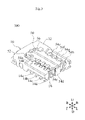
- FIG. 1 is a perspective view of the connector set 100.
- FIG. FIG. 2 is a perspective view of the connector set 100.
- FIG. FIG. 3 is a cutaway view of the connector set 100 of FIG.
- FIG. 4 is a diagram showing a cut surface of FIG.
- FIG. 5 is a left view of the first connection terminal 54i and the second connection terminal 14i.
- FIG. 6 is a left view of the first connection terminal 54j and the second connection terminal 14j.
- FIG. 7 is a left side view of the first connection terminal 54k and the second connection terminal 14k.
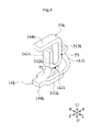
- FIG. 8 is a perspective view of the first connection terminal 54k and the second connection terminal 14k.
- FIG. 9 is a left view of the first connection terminal 54l and the second connection terminal 14l.
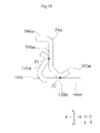
- FIG. 10 is a left view of the first connection terminal 54m and the second connection terminal 14m.
- FIG. 11 is a left view of the first connection terminal 54n and the second connection terminal 14n.
- FIG. 12 is a perspective view of the first connection terminal 54n and the second connection terminal 14n.
- FIG. 1 and 2 are perspective views of the connector set 100.
- FIG. FIG. 3 is a cutaway view of the connector set 100 of FIG.
- FIG. 4 is a diagram showing a cut surface of FIG.
- the direction in which the first connector 50 and the second connector 10 are arranged is defined as the vertical direction.
- the direction in which the second connection terminals 14a to 14d are arranged in the second connector 10 is defined as the horizontal direction.
- the horizontal direction is orthogonal to the vertical direction.
- a direction orthogonal to the left-right direction and the up-down direction is defined as the front-rear direction.
- the up-down direction, left-right direction, and front-back direction in this specification are defined for convenience of explanation, and do not have to correspond to the up-down direction, left-right direction, and front-back direction when the connector set 100 is used.
- the connector set 100 is used, for example, to connect two circuit boards.
- a connector set 100 includes a first connector 50 and a second connector 10 .
- the first connector 50 is positioned above the second connector 10 when the first connector 50 and the second connector 10 are connected.
- the first connector 50 includes a first fixed terminal 52, first connection terminals 54a-54h and a first support member 56. As shown in FIG. 1 and 2, the first connector 50 includes a first fixed terminal 52, first connection terminals 54a-54h and a first support member 56. As shown in FIG. 1
- the first support member 56 supports a first fixed terminal 52 and first connection terminals 54a to 54h, which will be described later.
- the first support member 56 has a rectangular shape when viewed in the vertical direction. A long side of the first support member 56 extends in the left-right direction. The short sides of the first support member 56 extend in the front-rear direction.
- the material of the first support member 56 is an insulating material. The material of the first support member 56 is, for example, resin.
- the first fixed terminal 52 is a conductor connected to ground potential.
- the first fixed terminal 52 includes a first fixed portion left portion 52L and a first fixed portion right portion 52R.
- the first fixing portion left portion 52L is provided at the left end portion of the first support member 56 .
- the first fixing portion right portion 52 ⁇ /b>R is provided at the right end portion of the first support member 56 .
- a portion of the first fixed terminal 52 is embedded in the first support member 56 . Thereby, the first fixed terminal 52 is supported by the first support member 56 .
- the first fixed terminal 52 is produced by bending a metal plate.
- the material of the first fixed terminal 52 is, for example, a copper-based material such as phosphor bronze.
- the first connection terminals 54a to 54h are conductors connected to signal potentials.
- the first connection terminals 54 a to 54 d are provided on the front portion of the first connector 50 .
- the first connection terminals 54a to 54d are arranged in a row in this order from right to left.
- the first connection terminals 54 e to 54 h are provided on the rear portion of the first connector 50 .
- the first connection terminals 54e to 54h are arranged in a row in this order from right to left.
- a portion of the first connection terminals 54 a to 54 h is embedded in the first support member 56 .
- the first connection terminals 54a to 54h are supported by the first support member 56.
- the first connection terminals 54a to 54h are produced by bending a bar-shaped metal member.
- the material of the first connection terminals 54a to 54h is, for example, a copper-based material such as phosphor bronze.
- the shapes of the first connection terminals 54a to 54h will be described in more detail.
- the first connection terminals 54a-54d have the same shape.
- the first connection terminals 54e to 54h have a shape symmetrical with respect to the first connection terminals 54a to 54d. Therefore, the shape of the first connection terminal 54d will be described as an example.
- the first connection terminal 54d includes a first connection portion 541d, a second connection portion 542d, a first connection portion 543d and a first lead-out portion 544d.
- the first connecting portion 541d, the second connecting portion 542d, the first connecting portion 543d, and the first lead-out portion 544d are connected in this order.
- the first lead-out portion 544d is used for connection with components outside the first connector 50.
- a component outside the first connector 50 is, for example, a circuit board.
- the first drawer portion 544d extends in the front-rear direction.
- the first lead-out portion 544 d is exposed to the outside of the first connector 50 from the upper surface of the first support member 56 .
- a front end of the first drawer portion 544 d is located in front of the first support member 56 .
- Such a first lead-out portion 544d is fixed to the electrode of the circuit board by soldering.
- the first connecting portion 543d connects a second connecting portion 542d and a first drawer portion 544d, which will be described later. Specifically, the first connecting portion 543d extends downward from the rear end of the first drawer portion 544d.
- the second connecting portion 542d extends forward from the lower end of the first connecting portion 543d.
- the first connecting portion 541d extends upward from the front end of the second connecting portion 542d.
- At least part of the rear surface SB of the first connection terminal 54d as described above is in contact with the first support member 56, as shown in FIGS.
- more than half of the rear surface SB of the first connection terminal 54 d in the vertical direction is in contact with the first support member 56 .
- the rear surface SB of the first connection terminal 54d is included in the first connecting portion 543d.
- the first connecting portion 543 d is positioned in front of the first support member 56 . Most of the first connecting portion 543 d except for the upper end portion is in contact with the first support member 56 . That is, there is no space between the first connecting portion 543d and the rear surface SB of the first support member 56. As shown in FIG.
- the second connector 10 includes a second fixed terminal 12, second connection terminals 14a-14h and a second support member 16. As shown in FIG. 1 and 2, the second connector 10 includes a second fixed terminal 12, second connection terminals 14a-14h and a second support member 16. As shown in FIG. 1
- the second support member 16 supports a second fixed terminal 12 and second connection terminals 14a to 14h, which will be described later.
- the second support member 16 has a rectangular shape when viewed in the vertical direction. A long side of the second support member 16 extends in the left-right direction. The short sides of the second support member 16 extend in the front-rear direction.
- the material of the second support member 16 is an insulating material. The material of the second support member 16 is, for example, resin.
- the second fixed terminal 12 is a conductor connected to ground potential.
- the second fixed terminal 12 has a rectangular frame shape when viewed in the vertical direction. Therefore, as shown in FIG. 2, an opening Op is provided in the vicinity of the center of the second fixed terminal 12 when viewed in the vertical direction.
- a long side of the second fixed terminal 12 extends in the left-right direction.
- the short side of the second fixed terminal 12 extends in the front-rear direction.
- a portion of the second fixed terminal 12 is embedded in the second support member 16 . Thereby, the second fixed terminal 12 is supported by the second support member 16 .
- the second fixed terminal 12 is produced by bending a metal plate.
- the material of the second fixed terminal 12 is, for example, a copper-based material such as phosphor bronze.
- the second connection terminals 14a to 14h are conductors connected to signal potentials.
- the second connection terminals 14 a to 14 d are provided on the front portion of the second connector 10 .
- the second connection terminals 14a to 14d are arranged in a row in this order from right to left.
- the second connection terminals 14e to 14h are provided at the rear portion of the second connector 10. As shown in FIG.
- the second connection terminals 14e to 14h are arranged in a line in this order from right to left.
- a portion of the second connection terminals 14 a to 14 h is embedded in the second support member 16 . Thereby, the second connection terminals 14a to 14h are supported by the second support member 16. As shown in FIG.
- the second connection terminals 14a to 14h are produced by bending a bar-shaped metal member.
- the material of the second connection terminals 14a to 14h is, for example, a copper-based material such as phosphor bronze.
- the shapes of the second connection terminals 14a to 14h will be described in more detail.
- the second connection terminals 14a-14d have the same shape.
- the second connection terminals 14e to 14h have a shape symmetrical in the front-rear direction with respect to the second connection terminals 14a to 14d. Therefore, the shape of the second connection terminal 14d will be described as an example.
- the second connection terminal 14d includes a third connection portion 141d, a fourth connection portion 142d, a second connection portion 143d and a second lead-out portion 144d.
- the fourth connecting portion 142d, the third connecting portion 141d, the second connecting portion 143d, and the second lead-out portion 144d are connected in this order.
- the second lead-out portion 144d is used for connection with components outside the second connector 10.
- a component outside the second connector 10 is, for example, a circuit board.
- the second drawer portion 144d extends in the front-rear direction.
- the second lead-out portion 144 d is exposed to the outside of the second connector 10 from the lower surface of the second support member 16 .
- a front end of the second drawer portion 144 d is located in front of the second support member 16 .
- the second lead-out portion 144d is located in front of a third connecting portion 141d, a fourth connecting portion 142d, and a second connecting portion 143d, which will be described later.
- Such a second lead-out portion 144d is fixed to the electrode of the circuit board by soldering.
- the second connecting portion 143d connects a third connecting portion 141d and a second drawer portion 144d, which will be described later.
- the second connecting portion 143d extends upward from the rear end of the second drawer portion 144d. Further, the upper end portion of the second drawer portion 144d is bent forward.
- the third connecting portion 141d extends downward from the upper end portion of the second connecting portion 143d.
- the second connecting portion 143d and the third connecting portion 141d have a U-shape inverted upside down when viewed in the horizontal direction. Therefore, when the third connecting portion 141d receives a leftward force, the third connecting portion 141d and the second connecting portion 143d are elastically deformed. As a result, the third connecting portion 141d is displaced leftward.
- the fourth connection portion 142d extends rearward from the lower end of the third connection portion 141d.
- the third connecting portion 141d is located in front of the fourth connecting portion 142d.
- the upper end of the fourth connecting portion 142d is located above the lower end of the third connecting portion 141d. Therefore, the fourth connection portion 142d has a V-shape that is inverted upside down when viewed in the left-right direction. That is, the fourth connection portion 142d extends rearward and upward from the lower end of the third connection portion 141d and then extends rearward and downward. Therefore, when the fourth connection portion 142d receives downward force, the third connection portion 141d and the fourth connection portion 142d are elastically deformed. As a result, the fourth connecting portion 142d is displaced downward.
- the first connector 50 is inserted from above the second connector 10 into the opening Op surrounded by the first fixed terminals 52, as shown in FIGS. Thereby, the first fixed terminal 52 is fixed to the second fixed terminal 12 . That is, the first fixed terminal 52 is electrically connected to the second fixed terminal 12 .
- the first connection terminals 54a-54h are electrically connected to the second connection terminals 14a-14h, respectively.
- the structure of connection between the first connection terminals 54a-54d and the second connection terminals 14a-14d is the same. Also, the structure of connection between the first connection terminals 54e to 54h and the second connection terminals 14e to 14h is symmetrical with the structure of connection between the first connection terminals 54a to 54d and the second connection terminals 14a to 14d. Therefore, the connection between the first connection terminal 54d and the second connection terminal 14d will be described as an example.
- the first connection terminal 54d is connected to the second connection terminal at the first contact position P1 and the second contact position P2.
- the first contact position P1 is located at the first connection portion 541d and the third connection portion 141d. Therefore, the first connection portion 541d contacts the third connection portion 141d at the first contact position P1.
- the first connecting portion 541d is positioned behind the third connecting portion 141d.
- the first connecting portion 541d pushes the third connecting portion 141d forward.
- the third connection portion 141d is displaced forward.
- the second connection terminal 14d is elastically deformed forward (front-rear direction).
- the second contact position P2 is located at the second connection portion 542d and the fourth connection portion 142d. Therefore, the second connection portion 542d contacts the fourth connection portion 142d at the second contact position P2.
- the second connection portion 542d is located above the fourth connection portion 142d. Therefore, the second connection portion 542d pushes the fourth connection portion 142d downward. As a result, the fourth connecting portion 142d is displaced downward.
- the second connection terminal 14d is elastically deformed downward (vertical direction).
- the connection state between the first connection terminals 54a to 54h of the first connector 50 and the second connection terminals 14a to 14h of the second connector 10 can be stabilized.
- the 1st connection terminal 54d and the 2nd connection terminal 14d are mentioned as an example, and are demonstrated.
- Contact between the first connection terminal 54d and the second connection terminal 14d at the first contact position P1 causes at least one of the first connection terminal 54d and the second connection terminal 14d to elastically deform in the front-rear direction at the first contact position P1. is doing. Therefore, even if the first connector 50 receives force in the rearward direction, the connected state between the first connection terminal 54d and the second connection terminal 14d at the first contact position P1 is maintained. At this time, the connection state between the first connection terminal 54d and the second connection terminal 14d at the second contact position P2 is also maintained.
- the connector set 100 even if the first connector 50 receives a force in the upward or rearward direction, the first connection terminal 54d and the second connection terminal at the first contact position P1 and the second contact position P2 are connected to each other. 14d is maintained. Therefore, according to the connector set 100, the connection state between the first connection terminals 54a to 54h of the first connector 50 and the second connection terminals 14a to 14h of the second connector 10 can be stabilized.
- the size of the connector set 100 can be reduced. More specifically, the second lead-out portion 144d is located in front of the third connection portion 141d and the fourth connection portion 142d.
- the first connecting portion 541d is located behind the third connecting portion 141d. Therefore, the second connection terminal 14d is less likely to be positioned behind the first connection terminal 54d. More precisely, it becomes difficult for the second connection terminal 14d to be positioned behind the first connecting portion 543d. Therefore, the rear surface SB of the first connection terminal 54 d can easily come into contact with the first support member 56 . That is, it becomes difficult for a space to exist between the rear surface SB of the first connection terminal 54 d and the first support member 56 . As a result, it becomes easy to bring the first connection terminal 54d closer to the center of the connector set 100 in the front-rear direction. As described above, according to the connector set 100, the size of the connector set 100 can be reduced.
- FIG. 5 is a left view of the first connection terminal 54i and the second connection terminal 14i.
- the first connection terminal 54i and the second connection terminal 14i differ from the first connection terminal 54d and the second connection terminal 14d in the structure of the fourth connection portion 142i. More specifically, the fourth connection portion 142i has a U shape rotated counterclockwise by 90° when viewed in the right direction. That is, the fourth connection portion 142i extends forward from the lower end of the third connection portion 141i and then extends rearward. Accordingly, when the fourth connection portion 142i receives downward force, the fourth connection portion 142i is elastically deformed. As a result, the fourth connecting portion 142i is displaced downward.
- the connector set 100 including the first connection terminals 54i and the second connection terminals 14i as described above also has the same effects as the connector set 100 including the first connection terminals 54d and the second connection terminals 14d.
- the fourth connection portion 142i has a U shape rotated counterclockwise by 90° when viewed in the right direction. Therefore, the fourth connecting portion 142i is easily deformed. That is, the springiness of the fourth connection portion 142i approaches the springiness of the third connection portion 141i. As a result, the connection state between the first connection terminals 54i and the second connection terminals 14i of the first connector 50 can be stabilized.
- FIG. 6 is a left view of the first connection terminal 54j and the second connection terminal 14j.
- the first connection terminal 54j and the second connection terminal 14j are different from the first connection terminal 54d and the second connection terminal 14d in that the second connection portion 143j does not exist and the position of the third connection portion 141j is different.
- the fourth connection portion 142j extends rearward from the rear end of the second lead-out portion 144j.
- the third connection portion 141j extends upward from the rear end of the fourth connection portion 142j. Thereby, the third connecting portion 141j is in contact with the first connecting portion 543j. Therefore, the first connecting portion 543j functions as a first connecting portion.
- the connector set 100 including the first connection terminal 54j and the second connection terminal 14j as described above also has the same effects as the connector set 100 including the first connection terminal 54d and the second connection terminal 14d. Also, the structure of the second connection terminal 14j is simplified.
- the third connection portion 141j is connected to the fourth connection portion 142j.
- the third connecting portion 141j is displaced in the front-rear direction
- the fourth connecting portion 142j is displaced in the vertical direction. More specifically, when the fourth connection portion 142j is pushed downward by the second connection portion 542j, the third connection portion 141j tends to fall forward. As a result, the third connecting portion 141j is pressed against the first connecting portion 543j. Therefore, the first connection terminal 54j and the second connection terminal 14j are more reliably brought into contact with each other at the first contact position P1 and the second contact position P2.
- FIG. 7 is a left side view of the first connection terminal 54k and the second connection terminal 14k.
- FIG. 8 is a perspective view of the first connection terminal 54k and the second connection terminal 14k.
- the first connection terminal 54k and the second connection terminal 14k are different from the first connection terminal 54j and the second connection terminal 14j in that they have a second connecting portion 143k. More specifically, the front end of the second connecting portion 143k is connected to the rear end of the second lead-out portion 144k. The rear end of the second connecting portion 143k is connected to the lower end of the third connecting portion 141k. Further, the fourth connecting portion 142k branches upward from the second connecting portion 143k.
- the connector set 100 including the first connection terminal 54k and the second connection terminal 14k as described above also has the same effects as the connector set 100 including the first connection terminal 54j and the second connection terminal 14j. Also, the current path is shortened in the first connection terminal 54k and the second connection terminal 14k. As a result, the parasitic inductance and parasitic capacitance generated in the first connection terminal 54k and the second connection terminal 14k are reduced.
- FIG. 9 is a left view of the first connection terminal 54l and the second connection terminal 14l.
- the first connection terminal 54l and the second connection terminal 14l differ from the first connection terminal 54d and the second connection terminal 14d in the connection structure of the second connecting portion 143l. More specifically, the front end of the second connecting portion 143l is connected to the rear end of the second drawer portion 144l. The rear end of the second connecting portion 143l is connected to the rear end of the fourth connecting portion 142l. Also, the third connecting portion 141l extends upward from the front end of the fourth connecting portion 142l.
- the connector set 100 including the first connection terminals 54l and the second connection terminals 14l as described above also has the same effects as the connector set 100 including the first connection terminals 54d and the second connection terminals 14d.
- the third connection portion 141l is connected to the fourth connection portion 142l.
- the third connecting portion 141l is displaced in the front-rear direction
- the fourth connecting portion 142l is displaced in the vertical direction. More specifically, when the fourth connection portion 142l is pushed downward by the second connection portion 542l, the third connection portion 141l tends to fall backward. As a result, the third connecting portion 141l is pressed against the first connecting portion 541l. Therefore, the first connection terminal 54l and the second connection terminal 14l are more reliably brought into contact with each other at the first contact position P1 and the second contact position P2.
- FIG. 10 is a left view of the first connection terminal 54m and the second connection terminal 14m.
- the first connection terminal 54m includes a first connection portion 541m, a second connection portion 542m, and a first lead-out portion 544m.
- the first drawer portion 544m extends in the front-rear direction.
- the first connection portion 541m extends downward from the front end of the first drawer portion 544m.
- the second connection portion 542m extends rearward from the lower end of the first connection portion 541m.
- the lower end of the second connecting portion 542m is located below the lower end of the first connecting portion 541m. Therefore, the second connection portion 542m has a V shape when viewed in the left-right direction. That is, the second connection portion 542m extends rearward and downward from the lower end of the first connection portion 541m and then extends rearward and upward. Therefore, when the second connection portion 542m receives an upward force, the second connection portion 542m is elastically deformed. As a result, the second connecting portion 542m is displaced upward.
- the second connection terminal 14m includes a third connection portion 141m, a fourth connection portion 142m and a second lead-out portion 144m.
- the second drawer portion 144m extends in the front-rear direction.
- the fourth connection portion 142m extends forward from the front end of the second drawer portion 144m.
- the third connection portion 141m extends upward from the front end of the fourth connection portion 142m.
- the second connection terminal 14m is elastically deformed in the front-rear direction at the first contact position P1. Specifically, the third connecting portion 141m is displaced forward. Also, at the second contact position P2, the first connection terminal 54m is elastically deformed in the vertical direction. Specifically, the second connecting portion 542m is displaced upward.
- the connector set 100 including the first connection terminals 54m and the second connection terminals 14m as described above also has the same effects as the connector set including the first connection terminals 54d and the second connection terminals 14d.
- FIG. 11 is a left view of the first connection terminal 54n and the second connection terminal 14n.
- FIG. 12 is a perspective view of the first connection terminal 54n and the second connection terminal 14n.
- the first connection terminal 54n and the second connection terminal 14n differ from the first connection terminal 54k and the second connection terminal 14k in the structure of the fourth connection portion 142n. More specifically, the fourth connection portion 142n has a U-shape rotated counterclockwise by 90° when viewed rearward.
- the connector set 100 including the first connection terminals 54n and the second connection terminals 14n as described above also has the same effects as the connector set including the first connection terminals 54k and the second connection terminals 14k. Also, the current path is shortened in the first connection terminal 54n and the second connection terminal 14n. As a result, the parasitic inductance and parasitic capacitance generated in the first connection terminal 54n and the second connection terminal 14n are reduced.
- the connector set according to the present invention is not limited to the connector set 100 according to the above embodiment, and can be modified within the scope of the gist thereof. Two or more of the first connection terminals 54d, 54i to 54n and the second connection terminals 14d, 14i to 14n may be selected and applied to the connector set 100 in combination.
- first connection terminals 54a to 54n and the second connection terminals 14a to 14n at the first contact position P1 By contacting the first connection terminals 54a to 54n and the second connection terminals 14a to 14n at the first contact position P1, the first connection terminals 54a to 54n and the second connection terminals 14a to 14n are connected at the first contact position P1. 14n may be elastically deformed in the front-rear direction. Similarly, contact between the first connection terminals 54a to 54n and the second connection terminals 14a to 14n at the second contact position P2 causes the first connection terminals 54a to 54n and the second connection terminal 14a to contact each other at the second contact position P2. 14n may be elastically deformed in the vertical direction.
- first connection terminal may be elastically deformed in the front-rear direction at the first contact position P1.
- the number of the first connection terminals 54a to 54h is not limited to eight.
- the number of first connection terminals may be 1 or more and 7 or less, or may be 9 or more.
- the number of the second connection terminals 14a to 14h is not limited to eight.
- the number of second connection terminals may be 1 or more and 7 or less, or may be 9 or more.
- first connection terminal and the second connection terminal may be in contact with each other at three or more locations.
- first fixed terminal 52 and the second fixed terminal 12 are not essential components.
- a ground potential may be connected to the second connection terminals 14a to 14n and the first connection terminals 54a to 54n.
- Second connector 12 Second fixed terminals 14a to 14n: Second connection terminal 16: Second support member 50: First connector 52: First fixed terminal 52L: First fixed portion Left portion 52R: First fixed portion Right parts 54a to 54n: first connection terminals 56: first support member 100: connector sets 141d, 141i, 141j, 141k, 141l, 141m: third connection parts 142d, 142i, 142j, 142k, 142l, 142m, 142n: Fourth connecting portions 143d, 143j, 143k, 143l: Second connecting portions 144d, 144j, 144k, 144l, 144m: Second lead-out portions 541d, 541j, 541l, 541m: First connecting portions 542d, 542j, 542l, 542m: Second connecting portion 543d: First connecting portions 544d, 544m: First lead-out portion P1: First contact position P2: Second contact position SB: Rear surface
Landscapes
- Details Of Connecting Devices For Male And Female Coupling (AREA)
Abstract
本発明は、第1コネクタ50及び第2コネクタ10を備えるコネクタセット100である。第1コネクタ50と第2コネクタ10とが接続されたときに、第1接続端子54dは、第1接触位置P1及び第2接触位置P2において第2接続端子14dに接触する。第1接触位置P1において第1接続端子54dと第2接続端子14dとが接触することにより、第1接触位置P1において第1接続端子54d又は第2接続端子14dの少なくとも一方が前後方向に弾性変形している。第2接触位置P2において第1接続端子54dと第2接続端子14dとが接触することにより、第2接触位置P2において第1接続端子54d又は第2接続端子14dの少なくとも一方が上下方向に弾性変形している。
Description
本発明は、第1コネクタ及び第2コネクタを備えるコネクタセットに関する。
従来のコネクタセットに関する発明としては、例えば、特許文献1に記載のコネクタが知られている。このコネクタは、雄側コネクタ及び雌側コネクタを備えている。雄側コネクタは、雄端子を含んでいる。雌側コネクタは、雌端子を含んでいる。雄側コネクタは、雌側コネクタの下に位置するように雌側コネクタに取り付けられている。このとき、雄端子と雌端子とは、2か所において接触している。具体的には、雄端子の上端は、雌端子に接触している。これにより1か所目の接続が実現されている。また、雌端子の先端は、雄端子の左面に接触している。このとき、雌端子の先端近傍が僅かに弾性変形することにより、雌端子の先端が雄端子の左面に押し付けられている。これにより2か所目の接続が実現されている。
ところで、特許文献1に記載のコネクタにおいて、雄端子と雌端子との接続状態を安定させたいという要望がある。
そこで、本発明の目的は、第1コネクタの第1接続端子と第2コネクタの第2接続端子との接続状態を安定させることができるコネクタセットを提供することである。
本願発明者は、第1コネクタの第1接続端子と第2コネクタの第2接続端子との接続状態を安定させることができるコネクタセットの検討にあたり、特許文献1に記載のコネクタセットの構造を調べた。すると、本願発明者は、特許文献1に記載のコネクタセットでは、雄側コネクタが下方向に力を受けると、雄端子と雌端子との接続状態が不安定になりやすいことに気が付いた。
より詳細には、雌端子の先端近傍が僅かに弾性変形することにより、雌端子の先端が雄端子の左面に押し付けられている。そのため、雄コネクタが雌コネクタに対して僅かに下方向に変位しても、雌端子の先端と雄端子の左面との接続状態は維持される。
一方、雄端子の上端は、雌端子に接触している。ただし、雄端子の上端近傍は、弾性変形していない。すなわち、雄端子の上端は、雌端子に押し付けられていない。そのため、雄コネクタが雌コネクタに対して僅かに下方向に変位すると、雄端子の上端が雌端子から外れる場合がある。
以上のように、特許文献1に記載のコネクタでは、雄コネクタが下方向に力を受けると、雄端子と雌端子とが接続されている部分の数が変化する。その結果、雄端子と雌端子との接続状態が不安定になりやすい。そこで、本願発明者は、以下に説明するコネクタセットに思い至った。
本発明の一形態に係るコネクタセットは、
第1コネクタ及び第2コネクタを備えているコネクタセットであって、
前記第1コネクタと前記第2コネクタとが接続されたときに、前記第1コネクタが前記第2コネクタの上に位置し、
前記第1コネクタは、
第1接続端子を、
含んでおり、
前記第2コネクタは、
第2接続端子を、
含んでおり、
前記第1コネクタと前記第2コネクタとが接続されたときに、前記第1接続端子は、第1接触位置及び第2接触位置において前記第2接続端子に接触し、
前記第1接触位置において前記第1接続端子と前記第2接続端子とが接触することにより、前記第1接触位置において前記第1接続端子又は前記第2接続端子の少なくとも一方が前後方向に弾性変形しており、
前記第2接触位置において前記第1接続端子と前記第2接続端子とが接触することにより、前記第2接触位置において前記第1接続端子又は前記第2接続端子の少なくとも一方が上下方向に弾性変形している。
第1コネクタ及び第2コネクタを備えているコネクタセットであって、
前記第1コネクタと前記第2コネクタとが接続されたときに、前記第1コネクタが前記第2コネクタの上に位置し、
前記第1コネクタは、
第1接続端子を、
含んでおり、
前記第2コネクタは、
第2接続端子を、
含んでおり、
前記第1コネクタと前記第2コネクタとが接続されたときに、前記第1接続端子は、第1接触位置及び第2接触位置において前記第2接続端子に接触し、
前記第1接触位置において前記第1接続端子と前記第2接続端子とが接触することにより、前記第1接触位置において前記第1接続端子又は前記第2接続端子の少なくとも一方が前後方向に弾性変形しており、
前記第2接触位置において前記第1接続端子と前記第2接続端子とが接触することにより、前記第2接触位置において前記第1接続端子又は前記第2接続端子の少なくとも一方が上下方向に弾性変形している。
以下に、本明細書における部材の位置関係について定義する。第1部材ないし第3部材は、コネクタセットの構成である。本明細書において、前後方向に並ぶ第1部材及び第2部材とは、以下の状態を示す。前後方向に垂直な方向に第1部材及び第2部材を見たときに、第1部材及び第2部材の両方が前後方向を示す任意の直線上に配置されている状態である。本明細書において、上下方向に見たときに前後方向に並ぶ第1部材及び第2部材とは、以下の状態を示す。上下方向に第1部材及び第2部材を見たときに、第1部材及び第2部材の両方が前後方向を示す任意の直線上に配置されている。この場合、上下方向とは異なる左右方向から第1部材及び第2部材を見ると、第1部材及び第2部材のいずれか一方が前後方向を示す任意の直線上に配置されていなくてもよい。なお、第1部材と第2部材とが接触していてもよい。第1部材と第2部材とが離れていてもよい。第1部材と第2部材との間に第3部材が存在していてもよい。この定義は、前後方向以外の方向にも適用される。
本明細書において、第1部材が第2部材の上に配置されるとは、以下の状態を指す。第1部材の少なくとも一部は、第2部材の真上に位置している。従って、上下方向に見て、第1部材は、第2部材と重なっている。この定義は、上下方向以外の方向にも適用される。
本明細書において、第1部材が第2部材より上に配置されるとは、第1部材の少なくとも一部が第2部材の真上に位置している場合、及び、第1部材が第2部材の真上に位置せずに第1部材が第2部材の斜め上に位置している場合を含む。この場合、上下方向に見て、第1部材は、第2部材と重なっていなくてもよい。斜め上とは、例えば、左上、右上である。この定義は、上下方向以外の方向にも適用される。
本明細書において、特に断りのない場合には、第1部材の各部について以下のように定義する。第1部材の前部とは、第1部材の前半分を意味する。第1部材の後部とは、第1部材の後半分を意味する。第1部材の左部とは、第1部材の左半分を意味する。第1部材の右部とは、第1部材の右半分を意味する。第1部材の上部とは、第1部材の上半分を意味する。第1部材の下部とは、第1部材の下半分を意味する。第1部材の前端とは、第1部材の前方向の端を意味する。第1部材の後端とは、第1部材の後方向の端を意味する。第1部材の左端とは、第1部材の左方向の端を意味する。第1部材の右端とは、第1部材の右方向の端を意味する。第1部材の上端とは、第1部材の上方向の端を意味する。第1部材の下端とは、第1部材の下方向の端を意味する。第1部材の前端部とは、第1部材の前端及びその近傍を意味する。第1部材の後端部とは、第1部材の後端及びその近傍を意味する。第1部材の左端部とは、第1部材の左端及びその近傍を意味する。第1部材の右端部とは、第1部材の右端及びその近傍を意味する。第1部材の上端部とは、第1部材の上端及びその近傍を意味する。第1部材の下端部とは、第1部材の下端及びその近傍を意味する。
本明細書における任意の2つの部材を第1部材及び第2部材と定義した場合、任意の2つの部材の関係は以下のような意味になる。本明細書において、第1部材が第2部材に支持されているとは、第1部材が第2部材に対して移動不可能に第2部材に取り付けられている(すなわち、固定されている)場合、及び、第1部材が第2部材に対して移動可能に第2部材に取り付けられている場合を含む。また、第1部材が第2部材に支持されているとは、第1部材が第2部材に直接に取り付けられている場合、及び、第1部材が第3部材を介して第2部材に取り付けられている場合の両方を含む。
本明細書において、第1部材が第2部材に保持されているとは、第1部材が第2部材に対して移動不可能に第2部材に取り付けられている(すなわち、固定されている)場合を含み、第1部材が第2部材に対して移動可能に第2部材に取り付けられている場合を含まない。また、第1部材が第2部材に保持されているとは、第1部材が第2部材に直接に取り付けられている場合、及び、第1部材が第3部材を介して第2部材に取り付けられている場合の両方を含む。
本明細書において、「第1部材と第2部材とが電気的に接続される」とは、第1部材と第2部材との間で電気が導通していることを意味する。従って、第1部材と第2部材とが接触していてもよいし、第1部材と第2部材とが接触していなくてもよい。第1部材と第2部材とが接触していない場合には、第1部材と第2部材との間に導電性を有する第3部材が配置されている。
本発明に係るコネクタセットによれば、第1コネクタの第1接続端子と第2コネクタの第2接続端子との接続状態を安定させることができる。
以下に、本発明の一実施形態に係るコネクタセット100について説明する。図1及び図2は、コネクタセット100の斜視図である。図3は、図1のコネクタセット100を切断した図である。図4は、図3の切断面を示した図である。
以下では、第1コネクタ50と第2コネクタ10とが並ぶ方向を上下方向と定義する。また、第2コネクタ10において第2接続端子14a~14dが並ぶ方向を左右方向と定義する。左右方向は、上下方向に直交する。また、左右方向及び上下方向に直交する方向を前後方向と定義する。ただし、本明細書における上下方向、左右方向及び前後方向は、説明の便宜上定義した方向であり、コネクタセット100の使用時における上下方向、左右方向及び前後方向と一致していなくてもよい。
コネクタセット100は、例えば、2つの回路基板を接続するために用いられる。コネクタセット100は、第1コネクタ50及び第2コネクタ10を備えている。第1コネクタ50と第2コネクタ10とが接続されたときに、第1コネクタ50が第2コネクタ10の上に位置する。
[第1コネクタの構造]
まず、第1コネクタ50の構造について説明する。図1及び図2に示すように、第1コネクタ50は、第1固定端子52、第1接続端子54a~54h及び第1支持部材56を含んでいる。
まず、第1コネクタ50の構造について説明する。図1及び図2に示すように、第1コネクタ50は、第1固定端子52、第1接続端子54a~54h及び第1支持部材56を含んでいる。
第1支持部材56は、後述する第1固定端子52及び第1接続端子54a~54hを支持している。第1支持部材56は、上下方向に見て、長方形状を有している。第1支持部材56の長辺は、左右方向に延びている。第1支持部材56の短辺は、前後方向に延びている。第1支持部材56の材料は、絶縁材料である。第1支持部材56の材料は、例えば、樹脂である。
第1固定端子52は、接地電位に接続される導体である。第1固定端子52は、図2に示すように、第1固定部左部52L及び第1固定部右部52Rを含んでいる。第1固定部左部52Lは、第1支持部材56の左端部に設けられている。第1固定部右部52Rは、第1支持部材56の右端部に設けられている。第1固定端子52の一部分は、第1支持部材56に埋め込まれている。これにより、第1固定端子52は、第1支持部材56に支持されている。第1固定端子52は、金属板に折り曲げ加工が施されることにより作製される。第1固定端子52の材料は、例えば、リン青銅等の銅系材料である。
第1接続端子54a~54hは、信号電位に接続される導体である。第1接続端子54a~54dは、第1コネクタ50の前部に設けられている。第1接続端子54a~54dは、右から左へとこの順に一列に並んでいる。第1接続端子54e~54hは、第1コネクタ50の後部に設けられている。第1接続端子54e~54hは、右から左へとこの順に一列に並んでいる。第1接続端子54a~54hの一部分は、第1支持部材56に埋め込まれている。これにより、第1接続端子54a~54hは、第1支持部材56に支持されている。第1接続端子54a~54hは、棒状の金属部材に折り曲げ加工が施されることにより作製される。第1接続端子54a~54hの材料は、例えば、リン青銅等の銅系材料である。
ここで、第1接続端子54a~54hの形状についてより詳細に説明する。第1接続端子54a~54dは同じ形状を有している。また、第1接続端子54e~54hは、第1接続端子54a~54dと前後対称な形状を有している。そこで、第1接続端子54dの形状を例に挙げて説明する。
第1接続端子54dは、図3及び図4に示すように、第1接続部541d、第2接続部542d、第1連結部543d及び第1引き出し部544dを含んでいる。第1接続部541d、第2接続部542d、第1連結部543d及び第1引き出し部544dは、この順に連結されている。
第1引き出し部544dは、第1コネクタ50外の部品との接続に用いられる。第1コネクタ50外の部品は、例えば、回路基板である。第1引き出し部544dは、前後方向に延びている。第1引き出し部544dは、第1支持部材56の上面から第1コネクタ50外に露出している。第1引き出し部544dの前端は、第1支持部材56より前に位置している。このような、第1引き出し部544dは、回路基板の電極に半田により固定される。
第1連結部543dは、後述する第2接続部542dと第1引き出し部544dとを連結する。具体的には、第1連結部543dは、第1引き出し部544dの後端から下方向に向かって延びている。第2接続部542dは、第1連結部543dの下端から前方向に向かって延びている。また、第1接続部541dは、第2接続部542dの前端から上方向に向かって延びている。
以上のような第1接続端子54dの後面SBの少なくとも一部は、図3及び図4に示すように、第1支持部材56に接触している。本実施形態では、第1接続端子54dの後面SBの上下方向の半分以上は、第1支持部材56に接触している。より詳細には、第1接続端子54dの後面SBは、第1連結部543dに含まれている。第1連結部543dは、第1支持部材56の前に位置している。そして、第1連結部543dの上端部を除く大部分は、第1支持部材56に接している。すなわち、第1連結部543dと第1支持部材56の後面SBとの間には空間が存在していない。
[第2コネクタの構造]
次に、第2コネクタ10の構造について説明する。図1及び図2に示すように、第2コネクタ10は、第2固定端子12、第2接続端子14a~14h及び第2支持部材16を含んでいる。
次に、第2コネクタ10の構造について説明する。図1及び図2に示すように、第2コネクタ10は、第2固定端子12、第2接続端子14a~14h及び第2支持部材16を含んでいる。
第2支持部材16は、後述する第2固定端子12及び第2接続端子14a~14hを支持している。第2支持部材16は、上下方向に見て、長方形状を有している。第2支持部材16の長辺は、左右方向に延びている。第2支持部材16の短辺は、前後方向に延びている。第2支持部材16の材料は、絶縁材料である。第2支持部材16の材料は、例えば、樹脂である。
第2固定端子12は、接地電位に接続される導体である。第2固定端子12は、上下方向に見て、長方形状の枠形状を有している。従って、図2に示すように、上下方向に見て、第2固定端子12の中央近傍には開口Opが設けられている。第2固定端子12の長辺は、左右方向に延びている。第2固定端子12の短辺は、前後方向に延びている。第2固定端子12の一部分は、第2支持部材16に埋め込まれている。これにより、第2固定端子12は、第2支持部材16に支持されている。第2固定端子12は、金属板に折り曲げ加工が施されることにより作製される。第2固定端子12の材料は、例えば、リン青銅等の銅系材料である。
第2接続端子14a~14hは、信号電位に接続される導体である。第2接続端子14a~14dは、第2コネクタ10の前部に設けられている。第2接続端子14a~14dは、右から左へとこの順に一列に並んでいる。第2接続端子14e~14hは、第2コネクタ10の後部に設けられている。第2接続端子14e~14hは、右から左へとこの順に一列に並んでいる。第2接続端子14a~14hの一部分は、第2支持部材16に埋め込まれている。これにより、第2接続端子14a~14hは、第2支持部材16に支持されている。また、第2接続端子14a~14hの一部分は、開口Opを介して第2コネクタ10から露出している。第2接続端子14a~14hは、棒状の金属部材に折り曲げ加工が施されることにより作製される。第2接続端子14a~14hの材料は、例えば、リン青銅等の銅系材料である。
ここで、第2接続端子14a~14hの形状についてより詳細に説明する。第2接続端子14a~14dは同じ形状を有している。また、第2接続端子14e~14hは、第2接続端子14a~14dと前後対称な形状を有している。そこで、第2接続端子14dの形状を例に挙げて説明する。
第2接続端子14dは、図3及び図4に示すように、第3接続部141d、第4接続部142d、第2連結部143d及び第2引き出し部144dを含んでいる。第4接続部142d、第3接続部141d、第2連結部143d及び第2引き出し部144dは、この順に連結されている。
第2引き出し部144dは、第2コネクタ10外の部品との接続に用いられる。第2コネクタ10外の部品は、例えば、回路基板である。第2引き出し部144dは、前後方向に延びている。第2引き出し部144dは、第2支持部材16の下面から第2コネクタ10外に露出している。第2引き出し部144dの前端は、第2支持部材16より前に位置している。また、第2引き出し部144dは、後述する第3接続部141d、第4接続部142d及び第2連結部143dより前に位置している。このような、第2引き出し部144dは、回路基板の電極に半田により固定される。
第2連結部143dは、後述する第3接続部141dと第2引き出し部144dとを連結する。具体的には、第2連結部143dは、第2引き出し部144dの後端から上方向に向かって延びている。また、第2引き出し部144dの上端部は、前方向に折れ曲がっている。第3接続部141dは、第2連結部143dの上端部から下方向に向かって延びている。これにより、第2連結部143d及び第3接続部141dは、左右方向に見て、上下が反転したU字形状を有している。そのため、第3接続部141dが左方向に力を受けると、第3接続部141d及び第2連結部143dが弾性変形する。その結果、第3接続部141dが左方向に変位する。
第4接続部142dは、第3接続部141dの下端から後方向に向かって延びている。これにより、第3接続部141dは、第4接続部142dより前に位置している。ただし、第4接続部142dの上端は、第3接続部141dの下端より上に位置している。そのため、第4接続部142dは、左右方向に見て、上下が反転したV字形状を有している。すなわち、第4接続部142dは、第3接続部141dの下端から後上方向に向かって延びた後に後下方向に向かって延びている。そのため、第4接続部142dが下方向に力を受けると、第3接続部141d及び第4接続部142dが弾性変形する。その結果、第4接続部142dが下方向に変位する。
[コネクタセットの構造]
次に、コネクタセット100の構造について説明する。第1コネクタ50は、図1及び図2に示すように、第1固定端子52に囲まれた開口Opに第2コネクタ10の上から挿入される。これにより、第1固定端子52は、第2固定端子12に固定される。すなわち、第1固定端子52は、第2固定端子12に電気的に接続される。
次に、コネクタセット100の構造について説明する。第1コネクタ50は、図1及び図2に示すように、第1固定端子52に囲まれた開口Opに第2コネクタ10の上から挿入される。これにより、第1固定端子52は、第2固定端子12に固定される。すなわち、第1固定端子52は、第2固定端子12に電気的に接続される。
第1接続端子54a~54hのそれぞれは、第2接続端子14a~14hに電気的に接続される。第1接続端子54a~54dと第2接続端子14a~14dとの接続の構造は同じである。また、第1接続端子54e~54hと第2接続端子14e~14hとの接続の構造は、第1接続端子54a~54dと第2接続端子14a~14dとの接続の構造と前後対称である。そこで、第1接続端子54dと第2接続端子14dとの接続を例に挙げて説明する。
第1コネクタ50と第2コネクタ10とが接続されたときに、図3及び図4に示すように、第1接続端子54dは、第1接触位置P1及び第2接触位置P2において第2接続端子14dに接触する。第1接触位置P1は、第1接続部541d及び第3接続部141dに位置している。従って、第1接続部541dは、第1接触位置P1において第3接続部141dに接触する。そして、第1接触位置P1において第1接続端子54dと第2接続端子14dとが接触することにより、第1接触位置P1において第1接続端子54d又は第2接続端子14dの少なくとも一方が前後方向に弾性変形している。本実施形態では、第1接続部541dは、第3接続部141dの後に位置している。従って、第1接続部541dは、第3接続部141dを前方向に押す。これにより、第3接続部141dが前方向に変位する。このように、第1接触位置P1において、第2接続端子14dが前方向(前後方向)に弾性変形している。
第2接触位置P2は、第2接続部542d及び第4接続部142dに位置している。従って、第2接続部542dは、第2接触位置P2において第4接続部142dに接触する。そして、第2接触位置P2において第1接続端子54dと第2接続端子14dとが接触することにより、第2接触位置P2において第1接続端子54d又は第2接続端子14dの少なくとも一方が上下方向に弾性変形している。本実施形態では、第2接続部542dは、第4接続部142dの上に位置している。従って、第2接続部542dは、第4接続部142dを下方向に押す。これにより、第4接続部142dが下方向に変位する。このように、第2接触位置P2において、第2接続端子14dが下方向(上下方向)に弾性変形している。
[効果]
コネクタセット100によれば、第1コネクタ50の第1接続端子54a~54hと第2コネクタ10の第2接続端子14a~14hとの接続状態を安定させることができる。以下では、第1接続端子54d及び第2接続端子14dを例に挙げて説明する。第1接触位置P1において第1接続端子54dと第2接続端子14dとが接触することにより、第1接触位置P1において第1接続端子54d又は第2接続端子14dの少なくとも一方が前後方向に弾性変形している。そのため、第1コネクタ50が後方向に力を受けたとしても、第1接触位置P1における第1接続端子54dと第2接続端子14dとの接続状態が維持される。このとき、第2接触位置P2における第1接続端子54dと第2接続端子14dとの接続状態も維持される。
コネクタセット100によれば、第1コネクタ50の第1接続端子54a~54hと第2コネクタ10の第2接続端子14a~14hとの接続状態を安定させることができる。以下では、第1接続端子54d及び第2接続端子14dを例に挙げて説明する。第1接触位置P1において第1接続端子54dと第2接続端子14dとが接触することにより、第1接触位置P1において第1接続端子54d又は第2接続端子14dの少なくとも一方が前後方向に弾性変形している。そのため、第1コネクタ50が後方向に力を受けたとしても、第1接触位置P1における第1接続端子54dと第2接続端子14dとの接続状態が維持される。このとき、第2接触位置P2における第1接続端子54dと第2接続端子14dとの接続状態も維持される。
また、第2接触位置P2において第1接続端子54dと第2接続端子14dとが接触することにより、第2接触位置P2において第1接続端子54d又は第2接続端子14dの少なくとも一方が上下方向に弾性変形している。これにより、第1コネクタ50が上方向に力を受けたとしても、第2接触位置P2における第1接続端子54dと第2接続端子14dとの接続状態が維持される。このとき、第1接触位置P1における第1接続端子54dと第2接続端子14dとの接続状態も維持される。
以上のように、コネクタセット100では、第1コネクタ50が上方向又は後方向に力を受けたとしても、第1接触位置P1及び第2接触位置P2における第1接続端子54dと第2接続端子14dとの接続状態が維持される。よって、コネクタセット100によれば、第1コネクタ50の第1接続端子54a~54hと第2コネクタ10の第2接続端子14a~14hとの接続状態を安定させることができる。
コネクタセット100によれば、コネクタセット100の小型化を図ることができる。より詳細には、第2引き出し部144dは、第3接続部141d及び第4接続部142dより前に位置している。そして、第1接続部541dは、第3接続部141dの後に位置している。従って、第2接続端子14dが、第1接続端子54dより後に位置しにくくなる。より正確には、第2接続端子14dが、第1連結部543dの後に位置しにくくなる。よって、第1接続端子54dの後面SBが、第1支持部材56に接触しやすくなる。すなわち、第1接続端子54dの後面SBと第1支持部材56との間に空間が存在しにくくなる。その結果、第1接続端子54dをコネクタセット100の前後方向の中央に近づけることが容易となる。以上より、コネクタセット100によれば、コネクタセット100の小型化を図ることができる。
(第1変形例)
以下に、第1変形例に係る第1接続端子54i及び第2接続端子14iについて図面を参照しながら説明する。図5は、第1接続端子54i及び第2接続端子14iの左面図である。
以下に、第1変形例に係る第1接続端子54i及び第2接続端子14iについて図面を参照しながら説明する。図5は、第1接続端子54i及び第2接続端子14iの左面図である。
第1接続端子54i及び第2接続端子14iは、第4接続部142iの構造において第1接続端子54d及び第2接続端子14dと相違する。より詳細には、第4接続部142iは、右方向に見て、反時計回りに90°回転したU字形状を有している。すなわち、第4接続部142iは、第3接続部141iの下端から前方向に向かって延びた後に後方向に向かって延びている。これにより、第4接続部142iが下方向に力を受けると、第4接続部142iが弾性変形する。その結果、第4接続部142iが下方向に変位する。
以上のような第1接続端子54i及び第2接続端子14iを備えるコネクタセット100においても、第1接続端子54d及び第2接続端子14dを備えるコネクタセット100と同じ作用効果を奏する。また、第4接続部142iは、右方向に見て、反時計回りに90°回転したU字形状を有している。そのため、第4接続部142iは、変形しやすい。すなわち、第4接続部142iのばね性が第3接続部141iのばね性に近づく。その結果、第1コネクタ50の第1接続端子54iと第2接続端子14iとの接続状態を安定させることができる。
(第2変形例)
以下に、第2変形例に係る第1接続端子54j及び第2接続端子14jについて図面を参照しながら説明する。図6は、第1接続端子54j及び第2接続端子14jの左面図である。
以下に、第2変形例に係る第1接続端子54j及び第2接続端子14jについて図面を参照しながら説明する。図6は、第1接続端子54j及び第2接続端子14jの左面図である。
第1接続端子54j及び第2接続端子14jは、第2連結部143jが存在しない点、及び、第3接続部141jの位置が異なる点において第1接続端子54d及び第2接続端子14dと相違する。より詳細には、第4接続部142jは、第2引き出し部144jの後端から後方向に向かって延びている。第3接続部141jは、第4接続部142jの後端から上方向に向かって延びている。これにより、第3接続部141jは、第1連結部543jに接触している。従って、第1連結部543jは、第1接続部として機能する。
以上のような第1接続端子54j及び第2接続端子14jを備えるコネクタセット100においても、第1接続端子54d及び第2接続端子14dを備えるコネクタセット100と同じ作用効果を奏する。また、第2接続端子14jでは、第2接続端子14jの構造が簡単になる。
また、第3接続部141jが第4接続部142jに接続されている。これにより、第3接続部141jが前後方向に変位すると共に、第4接続部142jが上下方向に変位する。より具体的には、第4接続部142jが第2接続部542jにより下方向に押されると、第3接続部141jが前方向に倒れようとする。これにより、第3接続部141jが第1連結部543jに押し付けられる。従って、第1接続端子54jと第2接続端子14jとが第1接触位置P1及び第2接触位置P2においてより確実に接触するようになる。
(第3変形例)
以下に、第3変形例に係る第1接続端子54k及び第2接続端子14kについて図面を参照しながら説明する。図7は、第1接続端子54k及び第2接続端子14kの左面図である。図8は、第1接続端子54k及び第2接続端子14kの斜視図である。
以下に、第3変形例に係る第1接続端子54k及び第2接続端子14kについて図面を参照しながら説明する。図7は、第1接続端子54k及び第2接続端子14kの左面図である。図8は、第1接続端子54k及び第2接続端子14kの斜視図である。
第1接続端子54k及び第2接続端子14kは、第2連結部143kを備えている点において第1接続端子54j及び第2接続端子14jと相違する。より詳細には、第2連結部143kの前端は、第2引き出し部144kの後端に接続されている。第2連結部143kの後端は、第3接続部141kの下端に接続されている。また、第4接続部142kは、第2連結部143kから上方向に枝分かれしている。以上のような第1接続端子54k及び第2接続端子14kを備えるコネクタセット100においても、第1接続端子54j及び第2接続端子14jを備えるコネクタセット100と同じ作用効果を奏する。また、第1接続端子54k及び第2接続端子14kでは、電流経路が短くなる。その結果、第1接続端子54k及び第2接続端子14kに発生する寄生インダクタンスや寄生容量が低減される。
(第4変形例)
以下に、第4変形例に係る第1接続端子54l及び第2接続端子14lについて図面を参照しながら説明する。図9は、第1接続端子54l及び第2接続端子14lの左面図である。
以下に、第4変形例に係る第1接続端子54l及び第2接続端子14lについて図面を参照しながら説明する。図9は、第1接続端子54l及び第2接続端子14lの左面図である。
第1接続端子54l及び第2接続端子14lは、第2連結部143lの接続構造において第1接続端子54d及び第2接続端子14dと相違する。より詳細には、第2連結部143lの前端は、第2引き出し部144lの後端に接続されている。第2連結部143lの後端は、第4接続部142lの後端に接続されている。また、第3接続部141lは、第4接続部142lの前端から上方向に向かって延びている。以上のような第1接続端子54l及び第2接続端子14lを備えるコネクタセット100においても、第1接続端子54d及び第2接続端子14dを備えるコネクタセット100と同じ作用効果を奏する。
また、第3接続部141lが第4接続部142lに接続されている。これにより、第3接続部141lが前後方向に変位すると共に、第4接続部142lが上下方向に変位する。より具体的には、第4接続部142lが第2接続部542lにより下方向に押されると、第3接続部141lが後方向に倒れようとする。これにより、第3接続部141lが第1接続部541lに押し付けられる。従って、第1接続端子54lと第2接続端子14lとが第1接触位置P1及び第2接触位置P2においてより確実に接触するようになる。
(第5変形例)
以下に、第5変形例に係る第1接続端子54m及び第2接続端子14mについて図面を参照しながら説明する。図10は、第1接続端子54m及び第2接続端子14mの左面図である。
以下に、第5変形例に係る第1接続端子54m及び第2接続端子14mについて図面を参照しながら説明する。図10は、第1接続端子54m及び第2接続端子14mの左面図である。
第1接続端子54mは、第1接続部541m、第2接続部542m及び第1引き出し部544mを含んでいる。第1引き出し部544mは、前後方向に延びている。第1接続部541mは、第1引き出し部544mの前端から下方向に向かって延びている。第2接続部542mは、第1接続部541mの下端から後方向に向かって延びている。ただし、第2接続部542mの下端は、第1接続部541mの下端より下に位置している。そのため、第2接続部542mは、左右方向に見て、V字形状を有している。すなわち、第2接続部542mは、第1接続部541mの下端から後下方向に向かって延びた後に後上方向に向かって延びている。そのため、第2接続部542mが上方向に力を受けると、第2接続部542mが弾性変形する。その結果、第2接続部542mが上方向に変位する。
第2接続端子14mは、第3接続部141m、第4接続部142m及び第2引き出し部144mを含んでいる。第2引き出し部144mは、前後方向に延びている。第4接続部142mは、第2引き出し部144mの前端から前方向に向かって延びている。第3接続部141mは、第4接続部142mの前端から上方向に向かって延びている。第3接続部141mが前方向に力を受けると、第3接続部141mが弾性変形する。その結果、第3接続部141mが前方向に変位する。
以上のような第1接続端子54m及び第2接続端子14mを備えるコネクタセット100では、第1接触位置P1において、第2接続端子14mが前後方向に弾性変形している。具体的には、第3接続部141mが前方向に変位している。また、第2接触位置P2において、第1接続端子54mが上下方向に弾性変形している。具体的には、第2接続部542mが上方向に変位している。以上のような第1接続端子54m及び第2接続端子14mを備えるコネクタセット100においても、第1接続端子54d及び第2接続端子14dを備えるコネクタセットと同じ作用効果を奏する。
(第6変形例)
以下に、第6変形例に係る第1接続端子54n及び第2接続端子14nについて図面を参照しながら説明する。図11は、第1接続端子54n及び第2接続端子14nの左面図である。図12は、第1接続端子54n及び第2接続端子14nの斜視図である。
以下に、第6変形例に係る第1接続端子54n及び第2接続端子14nについて図面を参照しながら説明する。図11は、第1接続端子54n及び第2接続端子14nの左面図である。図12は、第1接続端子54n及び第2接続端子14nの斜視図である。
第1接続端子54n及び第2接続端子14nは、第4接続部142nの構造において第1接続端子54k及び第2接続端子14kと相違する。より詳細には、第4接続部142nは、後方向に見て、反時計回りに90°回転したU字形状を有している。以上のような第1接続端子54n及び第2接続端子14nを備えるコネクタセット100においても、第1接続端子54k及び第2接続端子14kを備えるコネクタセットと同じ作用効果を奏する。また、第1接続端子54n及び第2接続端子14nでは、電流経路が短くなる。その結果、第1接続端子54n及び第2接続端子14nに発生する寄生インダクタンスや寄生容量が低減される。
(その他の実施形態)
本発明に係るコネクタセットは、前記実施形態に係るコネクタセット100に限らず、その要旨の範囲内において変更可能である。なお、第1接続端子54d,54i~54n及び第2接続端子14d,14i~14nの中から2種類以上を選択して組み合わせてコネクタセット100に適用してもよい。
本発明に係るコネクタセットは、前記実施形態に係るコネクタセット100に限らず、その要旨の範囲内において変更可能である。なお、第1接続端子54d,54i~54n及び第2接続端子14d,14i~14nの中から2種類以上を選択して組み合わせてコネクタセット100に適用してもよい。
なお、第1接触位置P1において第1接続端子54a~54nと第2接続端子14a~14nとが接触することにより、第1接触位置P1において第1接続端子54a~54n及び第2接続端子14a~14nの両方が前後方向に弾性変形してもよい。同様に、第2接触位置P2において第1接続端子54a~54nと第2接続端子14a~14nとが接触することにより、第2接触位置P2において第1接続端子54a~54n及び第2接続端子14a~14nの両方が上下方向に弾性変形してもよい。
なお、第1接触位置P1において、第1接続端子が前後方向に弾性変形してもよい。
なお、第1コネクタ50において、第1接続端子54a~54hの数は8個に限らない。第1接続端子の数は、1個以上7個以下であってもよいし、9個以上であってもよい。
なお、第2コネクタ10において、第2接続端子14a~14hの数は8個に限らない。第2接続端子の数は、1個以上7個以下であってもよいし、9個以上であってもよい。
なお、第1接続端子及び第2接続端子は、3か所以上において接触していてもよい。
なお、第1固定端子52及び第2固定端子12は、必須の構成ではない。
なお、第2接続端子14a~14n及び第1接続端子54a~54nには、接地電位が接続されてもよい。
10:第2コネクタ
12:第2固定端子
14a~14n:第2接続端子
16:第2支持部材
50:第1コネクタ
52:第1固定端子
52L:第1固定部左部
52R:第1固定部右部
54a~54n:第1接続端子
56:第1支持部材
100:コネクタセット
141d,141i,141j,141k,141l,141m:第3接続部
142d,142i,142j,142k,142l,142m,142n:第4接続部
143d,143j,143k,143l:第2連結部
144d,144j,144k,144l,144m:第2引き出し部
541d,541j,541l,541m:第1接続部
542d,542j,542l,542m:第2接続部
543d:第1連結部
544d,544m:第1引き出し部
P1:第1接触位置
P2:第2接触位置
SB:後面
12:第2固定端子
14a~14n:第2接続端子
16:第2支持部材
50:第1コネクタ
52:第1固定端子
52L:第1固定部左部
52R:第1固定部右部
54a~54n:第1接続端子
56:第1支持部材
100:コネクタセット
141d,141i,141j,141k,141l,141m:第3接続部
142d,142i,142j,142k,142l,142m,142n:第4接続部
143d,143j,143k,143l:第2連結部
144d,144j,144k,144l,144m:第2引き出し部
541d,541j,541l,541m:第1接続部
542d,542j,542l,542m:第2接続部
543d:第1連結部
544d,544m:第1引き出し部
P1:第1接触位置
P2:第2接触位置
SB:後面
Claims (8)
- 第1コネクタ及び第2コネクタを備えているコネクタセットであって、
前記第1コネクタと前記第2コネクタとが接続されたときに、前記第1コネクタが前記第2コネクタの上に位置し、
前記第1コネクタは、
第1接続端子を、
含んでおり、
前記第2コネクタは、
第2接続端子を、
含んでおり、
前記第1コネクタと前記第2コネクタとが接続されたときに、前記第1接続端子は、第1接触位置及び第2接触位置において前記第2接続端子に接触し、
前記第1接触位置において前記第1接続端子と前記第2接続端子とが接触することにより、前記第1接触位置において前記第1接続端子又は前記第2接続端子の少なくとも一方が前後方向に弾性変形しており、
前記第2接触位置において前記第1接続端子と前記第2接続端子とが接触することにより、前記第2接触位置において前記第1接続端子又は前記第2接続端子の少なくとも一方が上下方向に弾性変形している、
コネクタセット。 - 前記第1接続端子は、第1接続部、第2接続部及び第1引き出し部を含んでおり、
前記第2接続端子は、第3接続部、第4接続部及び第2引き出し部を含んでおり、
前記第1引き出し部は、前記第1コネクタ外の部品との接続に用いられ、
前記第2引き出し部は、前記第2コネクタ外の部品との接続に用いられ、
前記第1接続部は、前記第1接触位置において前記第3接続部に接触し、
前記第2接続部は、前記第2接触位置において前記第4接続部に接触し、
前記第2引き出し部は、前記第3接続部及び前記第4接続部より前に位置しており、
前記第1接続部は、前記第3接続部の後に位置している、
請求項1に記載のコネクタセット。 - 前記第1コネクタは、
前記第1接続端子を支持する第1支持部材を、
更に含んでおり、
前記第1接続端子の後面の少なくとも一部分は、前記第1支持部材に接触している、
請求項2に記載のコネクタセット。 - 前記第1支持部材の後面の上下方向の半分以上は、前記第1支持部材に接触している、
請求項3に記載のコネクタセット。 - 前記第2接触位置において、前記第1接続端子が上下方向に弾性変形している、
請求項1ないし請求項4のいずれかに記載のコネクタセット。 - 前記第2接触位置において、前記第2接続端子が上下方向に弾性変形している、
請求項1ないし請求項4のいずれかに記載のコネクタセット。 - 前記第1接触位置において、前記第2接続端子が前後方向に弾性変形している、
請求項1ないし請求項6のいずれかに記載のコネクタセット。 - 前記第3接続部が前記第4接続部に接続されており、
前記第3接続部が前後方向に変位し、
前記第4接続部が上下方向に変位する、
請求項2に記載のコネクタセット。
Applications Claiming Priority (2)
| Application Number | Priority Date | Filing Date | Title |
|---|---|---|---|
| JP2021053492 | 2021-03-26 | ||
| JP2021-053492 | 2021-03-26 |
Publications (1)
| Publication Number | Publication Date |
|---|---|
| WO2022201847A1 true WO2022201847A1 (ja) | 2022-09-29 |
Family
ID=83395400
Family Applications (1)
| Application Number | Title | Priority Date | Filing Date |
|---|---|---|---|
| PCT/JP2022/003196 Ceased WO2022201847A1 (ja) | 2021-03-26 | 2022-01-28 | コネクタセット |
Country Status (1)
| Country | Link |
|---|---|
| WO (1) | WO2022201847A1 (ja) |
Cited By (1)
| Publication number | Priority date | Publication date | Assignee | Title |
|---|---|---|---|---|
| JP2024070002A (ja) * | 2022-11-10 | 2024-05-22 | 株式会社村田製作所 | コネクタセット |
Citations (4)
| Publication number | Priority date | Publication date | Assignee | Title |
|---|---|---|---|---|
| JPH11329548A (ja) * | 1998-05-08 | 1999-11-30 | Yazaki Corp | 高圧電線の接続構造 |
| JP2003297458A (ja) * | 2002-03-29 | 2003-10-17 | Molex Inc | 基板接続用コネクタ |
| JP2012009373A (ja) * | 2010-06-28 | 2012-01-12 | Molex Inc | 基板対基板コネクタ |
| JP2017139226A (ja) * | 2016-02-05 | 2017-08-10 | ヒロセコリア カンパニー リミテッド | プラグコネクタ、ソケットコネクタ及び電気コネクタ組立体 |
-
2022
- 2022-01-28 WO PCT/JP2022/003196 patent/WO2022201847A1/ja not_active Ceased
Patent Citations (4)
| Publication number | Priority date | Publication date | Assignee | Title |
|---|---|---|---|---|
| JPH11329548A (ja) * | 1998-05-08 | 1999-11-30 | Yazaki Corp | 高圧電線の接続構造 |
| JP2003297458A (ja) * | 2002-03-29 | 2003-10-17 | Molex Inc | 基板接続用コネクタ |
| JP2012009373A (ja) * | 2010-06-28 | 2012-01-12 | Molex Inc | 基板対基板コネクタ |
| JP2017139226A (ja) * | 2016-02-05 | 2017-08-10 | ヒロセコリア カンパニー リミテッド | プラグコネクタ、ソケットコネクタ及び電気コネクタ組立体 |
Cited By (2)
| Publication number | Priority date | Publication date | Assignee | Title |
|---|---|---|---|---|
| JP2024070002A (ja) * | 2022-11-10 | 2024-05-22 | 株式会社村田製作所 | コネクタセット |
| JP7735982B2 (ja) | 2022-11-10 | 2025-09-09 | 株式会社村田製作所 | コネクタセット |
Similar Documents
| Publication | Publication Date | Title |
|---|---|---|
| CN103748745B (zh) | 母端子以及采用所述母端子的连接器 | |
| US10439315B2 (en) | Connector assembly | |
| US20160020572A1 (en) | Method for molding electrical connector | |
| US10326214B2 (en) | Cable connector assembly | |
| TW201929340A (zh) | 連接器系統 | |
| JP3161828U (ja) | 電気コネクタ及びその導電端子 | |
| EP2330693B1 (en) | Electric connector | |
| CN203445280U (zh) | 电连接器 | |
| CN102629711B (zh) | 用于产生电插塞连接的插座 | |
| TW201032404A (en) | Electrical connector | |
| TWM436971U (en) | Board-to-board connector | |
| CN104716505A (zh) | 插座连接器及与之对接的插头连接器 | |
| WO2022201847A1 (ja) | コネクタセット | |
| CN112186390A (zh) | 电连接器及其制造方法 | |
| US12476423B2 (en) | Electrical connector with an improved grounding member | |
| JP2016184575A (ja) | ケーブルコネクタ組立体 | |
| US7682173B2 (en) | Electrical connector with improved contacts | |
| KR20150118016A (ko) | Usb 리셉터클 | |
| JP7405116B2 (ja) | コネクタ | |
| JP2017079102A (ja) | 端子及びコネクタ | |
| TWM646833U (zh) | 小型高電流電連接器 | |
| JP2024130446A (ja) | コネクタ | |
| JP2023111019A (ja) | コネクタ | |
| WO2018147055A1 (ja) | 板状導電部材の接続構造及び板状導電路 | |
| TW200945706A (en) | Power connector and terminal resisting structure thereof |
Legal Events
| Date | Code | Title | Description |
|---|---|---|---|
| 121 | Ep: the epo has been informed by wipo that ep was designated in this application |
Ref document number: 22774649 Country of ref document: EP Kind code of ref document: A1 |
|
| NENP | Non-entry into the national phase |
Ref country code: DE |
|
| 122 | Ep: pct application non-entry in european phase |
Ref document number: 22774649 Country of ref document: EP Kind code of ref document: A1 |
|
| NENP | Non-entry into the national phase |
Ref country code: JP |