WO2022201702A1 - レンズ鏡筒および撮像装置 - Google Patents
レンズ鏡筒および撮像装置 Download PDFInfo
- Publication number
- WO2022201702A1 WO2022201702A1 PCT/JP2021/047843 JP2021047843W WO2022201702A1 WO 2022201702 A1 WO2022201702 A1 WO 2022201702A1 JP 2021047843 W JP2021047843 W JP 2021047843W WO 2022201702 A1 WO2022201702 A1 WO 2022201702A1
- Authority
- WO
- WIPO (PCT)
- Prior art keywords
- bearing
- guide shaft
- holding frame
- lens holding
- contact
- Prior art date
Links
- 238000003384 imaging method Methods 0.000 title claims description 8
- 230000003287 optical effect Effects 0.000 claims abstract description 58
- 230000007246 mechanism Effects 0.000 claims abstract description 53
- 239000003302 ferromagnetic material Substances 0.000 claims description 5
- 230000001105 regulatory effect Effects 0.000 claims description 5
- 230000002093 peripheral effect Effects 0.000 description 23
- 230000006835 compression Effects 0.000 description 20
- 238000007906 compression Methods 0.000 description 20
- 238000010586 diagram Methods 0.000 description 12
- 230000004048 modification Effects 0.000 description 9
- 238000012986 modification Methods 0.000 description 9
- 230000008859 change Effects 0.000 description 4
- 230000005291 magnetic effect Effects 0.000 description 4
- 230000012447 hatching Effects 0.000 description 3
- 239000000470 constituent Substances 0.000 description 2
- 230000004907 flux Effects 0.000 description 2
- 239000000696 magnetic material Substances 0.000 description 2
- 239000002184 metal Substances 0.000 description 2
- 239000011347 resin Substances 0.000 description 2
- 229920005989 resin Polymers 0.000 description 2
- 238000006243 chemical reaction Methods 0.000 description 1
- 239000013256 coordination polymer Substances 0.000 description 1
- 230000003993 interaction Effects 0.000 description 1
- 238000004804 winding Methods 0.000 description 1
Images


Classifications
-
- G—PHYSICS
- G02—OPTICS
- G02B—OPTICAL ELEMENTS, SYSTEMS OR APPARATUS
- G02B7/00—Mountings, adjusting means, or light-tight connections, for optical elements
- G02B7/02—Mountings, adjusting means, or light-tight connections, for optical elements for lenses
-
- G—PHYSICS
- G02—OPTICS
- G02B—OPTICAL ELEMENTS, SYSTEMS OR APPARATUS
- G02B7/00—Mountings, adjusting means, or light-tight connections, for optical elements
- G02B7/02—Mountings, adjusting means, or light-tight connections, for optical elements for lenses
- G02B7/04—Mountings, adjusting means, or light-tight connections, for optical elements for lenses with mechanism for focusing or varying magnification
Definitions
- a lens barrel is required to have good optical performance (for example, Patent Document 1).
- the lens barrel includes a lens holding frame that holds a lens, a guide shaft that guides the lens holding frame in the optical axis direction, and is supported by the lens holding frame and contacts the guide shaft.
- a plurality of abutment portions in contact with each other, and an urging mechanism that urges the lens holding frame against the guide shaft so that the plurality of abutment portions are pressed against the guide shaft are provided.
- an imaging device includes the lens barrel and an imaging element.
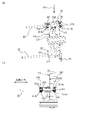
- FIG. 1 is a diagram showing a camera including a lens barrel and a camera body according to the first embodiment.
- FIG. 2(A) is a perspective view showing the configuration of the second fixed barrel
- FIG. 2(B) is a diagram showing the schematic configuration of the voice coil motor.
- 3A is a schematic perspective view of the lens holding frame
- FIG. 3B is a view of the lens holding frame viewed from the direction of arrow A1 in FIG. 3A.
- FIG. 4 is a cross-sectional view of the vicinity of the first support portion of the lens holding frame.
- 5 is a cross-sectional view taken along the line AA in FIG. 4.
- FIG. 6 is an enlarged cross-sectional view of the vicinity of the first support portion in FIG. 5.
- FIG. 7A is an exploded perspective view of the biasing mechanism
- FIG. 7B is a cross-sectional view of the bearing support.
- FIG. 8(A) is a perspective view for explaining the configuration of the eccentric mechanism
- FIG. 8(B) is a plan view of an eccentric portion provided in the eccentric mechanism
- FIG. 8(C) is a It is a perspective view of the fixing
- FIGS. 9A and 9B are diagrams illustrating changes in the position of the central axis of the bearing with respect to the lens holding frame.
- 10(A) and 10(B) are diagrams for explaining the adjustment of the position of the central axis of the third lens group on a plane perpendicular to the optical axis, and FIGS.
- FIGS. 11(A) and 11(B) are diagrams for explaining adjustment of the inclination of the central axis of the third lens group with respect to the optical axis.
- FIGS. 11(A) and 11(B) are diagrams illustrating another example of arrangement of the first bearing, the second bearing, and the third bearing.
- FIG. 12A is a perspective view showing a lens holding frame according to another example of the first embodiment
- FIG. 12B is a side view of the lens holding frame according to another example of the first embodiment.
- FIG. 13 is a cross-sectional view taken along line DD of FIG. 12(B).
- FIG. 14A is a perspective view showing a lens holding frame according to the second embodiment, FIG.
- FIG. 14B is a cross-sectional view of the lens holding frame according to the second embodiment, and FIG. 14B is a cross-sectional view taken along line CC of FIG. 14B.
- FIG. FIG. 15A is a schematic perspective view of a lens holding frame according to the third embodiment, and FIG. 15B is a cross-sectional view of the vicinity of a second support portion of the lens holding frame according to the third embodiment.
- FIGS. 16A and 16B illustrate the positional relationship between the first bearing and second bearing supported by the lens holding frame and the third bearing included in the biasing mechanism according to the third embodiment. It is a figure for doing. It is a figure explaining the structure of the mechanism which suppresses the looseness between a rotation control bar and a 4th bearing.
- FIG. 18A is a perspective view of a lens holding frame according to a modification
- FIG. 18B is a view of the lens holding frame according to the modification as viewed from the direction indicated by arrow A51 in FIG. 18A. is.
- FIG. 1 is a diagram showing a camera 1 including a lens barrel 100 and a camera body 101 according to the first embodiment.
- the lens barrel 100 is detachable from the camera body 101, but the lens barrel 100 and the camera body 101 may be integrated.
- the camera body 101 includes an image sensor, a control unit, and the like inside.
- the imaging element is composed of a photoelectric conversion element such as a CCD (Charge Coupled Device), for example, and converts the subject image formed by the imaging optical system (lens barrel 100 attached to the camera body 101) into an electrical signal. .
- CCD Charge Coupled Device
- the control unit includes a CPU (Central Processing Unit) and the like, and centrally controls the operation of the camera 1 as a whole, including the focusing drive of the camera body 101 and the attached lens barrel 100 .
- CPU Central Processing Unit
- the lens barrel 100 includes a first fixed barrel 10 and a second fixed barrel 20.
- the first fixed barrel 10 is composed of a plurality of parts in this embodiment, it may be composed of a single part.
- a lens mount LM is fixed to the first fixed barrel 10 to allow the lens barrel 100 to be detachable from the camera body 101 .
- the lens barrel 100 includes first to seventh lens groups L1 to L7 sequentially arranged along the common optical axis OA.
- the third lens group L3 is held by the lens holding frame F3, and the other lens groups are held by the first fixed barrel 10.
- each of the first to seventh lens groups L1 to L7 may be composed of a plurality of lenses.
- the first, second, fourth to seventh lens groups L1, L2, L4 to L7 may be held by a lens holding frame movable in the direction of the optical axis OA instead of the first fixed barrel 10. .
- FIG. 2(A) is a perspective view showing the configuration of the second fixed cylinder 20.
- FIG. 2(A) a guide bar 22 and a rotation restricting bar 23 are fixed to the second fixed cylinder 20 .
- the guide bar 22 guides the lens holding frame F3 in the optical axis direction.
- the rotation restricting bar 23 restricts rotation of the lens holding frame F3 about the guide bar 22 .
- a voice coil motor (VCM) 50 for moving the lens holding frame F3 in the direction of the optical axis OA is provided inside the second fixed barrel 20.
- VCMs 50 are provided at two locations in the second fixed barrel 20, but the number of VCMs 50 is not limited to this embodiment, and may be one or three or more. .
- FIG. 2(B) is a diagram showing a schematic configuration of the VCM 50.
- the VCM 50 has a first side yoke 501a and a second side yoke 501b having length in the optical axis OA direction, and has a length in the optical axis OA direction and is located between the first side yoke 501a and the second side yoke 501b. and a center yoke 502 arranged.
- the VCM 50 also includes an upper yoke 503a connecting one end of the first side yoke 501a, the second side yoke 501b, and the center yoke 502 in the optical axis OA direction; and a lower yoke 503b connecting the other end of the yoke 502 in the optical axis OA direction. Thereby, a closed magnetic circuit is formed.
- a first magnet 504a is arranged on the side surface of the first side yoke 501a on the center yoke 502 side, and a second magnet 504b is arranged on the side surface of the second side yoke 501b on the center yoke 502 side.
- the first magnet 504a is arranged, for example, so that the center yoke 502 side becomes the north pole, and the second magnet 504b is also arranged so that the center yoke 502 side becomes the north pole.
- the VCM 50 also has a coil 505 that penetrates the center yoke 502 . There is a slight gap between the inner peripheral surface of the coil 505 and the center yoke 502, and the coil 505 is movable in the direction of the optical axis OA. Coil 505 is configured such that the direction of the magnetic flux converging on center yoke 502 from first side yoke 501 a and second side yoke 501 b is perpendicular to the winding direction of coil 505 .
- a drive signal (current) is input to the coil 505 .
- the coil 505 moves in the direction of the optical axis OA due to the magnetic forces of the first magnet 504a and the second magnet 504b. More specifically, the coil 505 moves in the direction of the optical axis OA due to the electromagnetic interaction between the current-carrying coil 505 and the first magnet 504a and the second magnet 504b.
- the moving direction of the coil 505 can be switched between the object side and the camera body 101 side (image plane side). Further, by changing the value of the current flowing through the coil 505, the driving force and moving speed of the coil 505 can be changed.
- the third lens group L3 is a focus lens group and is moved by the VCM 50 in the optical axis OA direction to perform focus adjustment. More specifically, since the lens holding frame F3 that holds the third lens group L3 is connected to the coil 505 of the VCM 50, when the coil 505 moves in the optical axis OA direction, the third lens group L3 moves toward the optical axis OA. direction is moved. A stepping motor or an ultrasonic motor may be used instead of the VCM 50 to move the third lens group L3.
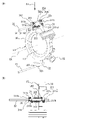
- FIG. 3(A) is a schematic perspective view of the lens holding frame F3
- FIG. 3(B) is a view of the lens holding frame F3 viewed from the direction of arrow A1 in FIG. 3(A).
- FIG. 4 is a cross-sectional view of the vicinity of the first support portion 31 of the lens holding frame F3.
- 5 is a cross-sectional view taken along line AA in FIG. 4
- FIG. 6 is a cross-sectional view enlarging the vicinity of the first support portion 31 in FIG.
- hatching indicating the cross section of the first support portion 31 and the guide bar 22 is omitted
- FIG. 6 hatching indicating the cross section of the guide bar 22 is omitted.
- the lens holding frame F3 has a cylindrical portion 30 that holds the third lens group L3.
- a first support portion 31 for supporting, a second support portion 32 for supporting a fourth bearing 321 to be described later, and a holding portion 33 for holding a coil 505 (see FIG. 2B) of the VCM 50 are provided.
- the holding portions 33 are provided at two locations corresponding to the number of VCMs 50 (two).
- the multiple bearings 311 have a first bearing 311a and a second bearing 311b.
- first bearing 311a and second bearing 311b are provided.
- first bearing 311a and the second bearing 311b are referred to as the bearing 311 when there is no particular need to distinguish between them.
- the direction in which the first bearing 311a contacts the guide bar 22 (direction indicated by arrow A14) and the direction in which the second bearing 311b contacts the guide bar 22 (direction indicated by arrow A15) are A predetermined angle ⁇ is formed.
- the direction in which the first bearing 311a contacts the guide bar 22 and the direction in which the second bearing 311b contacts the guide bar 22 intersect.
- the predetermined angle ⁇ is, for example, greater than 0° and smaller than 180°. From the viewpoint of efficiently distributing the force of the compression spring 353, which will be described later, to the first bearing 311a and the second bearing 311b, the predetermined angle ⁇ is preferably 30° or more and 120° or less.
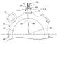
- a contact point CP1 where the first bearing 311a and the guide bar 22 abut and a contact point CP1 where the second bearing 311b and the guide bar 22 abut.
- the abutment point CP ⁇ b>2 is positioned radially inner than the center axis AX ⁇ b>1 of the guide bar 22 .
- a straight line connecting the central axis AX1 of the guide bar 22 and the optical axis OA extends between the contact point CP1 and the optical axis OA.
- the straight line connecting the central axis AX1 of the guide bar 22 and the optical axis OA is longer than the straight line LN2 connecting the contact point CP2 and the optical axis OA.
- the contact point CP1 and the contact point CP2 are located on the outer peripheral side of the central axis AX1 of the guide bar 22 in the radial direction of the circle centered on the optical axis OA. It can be made smaller in the radial direction.
- the biasing mechanism 35A biases the lens holding frame F3 against the guide bar 22 so that the first bearing 311a and the second bearing 311b are pressed against the guide bar 22. attached to the
- FIG. 7(A) is a perspective view of the biasing mechanism 35A
- FIG. 7(B) is a cross-sectional view of the bearing support portion 352.
- FIG. The biasing mechanism 35A includes a third bearing 351 that contacts the guide bar 22 and a bearing support portion 352 that supports the third bearing 351, as shown in FIGS. 4 and 7A.
- the bearing support portion 352 has a hole portion 352e through which the third bearing 351 protrudes.
- the bearing support part 352 is provided with the fitting part 352d fitted with the inner peripheral surface of the inner ring
- the bearing support portion 352 is not fixed to the lens holding frame F3. In other words, the bearing support portion 352 is movable with respect to the lens holding frame F3.
- the biasing mechanism 35A includes a facing portion 354a facing the bearing support portion 352, a facing portion 354a, and a lens holding frame F3.
- a fixing portion 354 having a pair of connecting portions 354b to be connected is provided.
- the connecting portion 354b of the fixing portion 354 is connected to the lens holding frame F3 by screws 355 or the like, as shown in FIGS. 3A and 3B.
- the biasing mechanism 35A includes a compression spring 353 that contacts the opposing portion 354a and biases the third bearing 351 toward the guide bar 22.
- the compression spring 353 is attached to the column member 352 c of the bearing support portion 352 .
- the height of the compression spring 353 is higher than the height of the column member 352c.
- the bearing support portion 352 when the fixed portion 354 moves along the optical axis OA along with the lens holding frame F3, the bearing support portion 352 also moves along the optical axis OA along with the fixed portion 354 .
- the column member 352c may be provided on the fixed portion 354 instead of on the bearing support portion 352 .
- the compression spring 353 biases the bearing support portion 352 toward the guide bar 22 (in the direction indicated by arrow A11 in FIG. 4). As a result, the third bearing 351 supported by the bearing support portion 352 is also biased toward the guide bar 22 (see arrow A12 in FIGS. 4 and 6) and pressed against the guide bar 22 . Also, the compression spring 353 urges the fixed portion 354 in the direction opposite to the guide bar 22 (the direction indicated by the arrow A16 in FIG. 4). As a result, the lens holding frame F3 connected to the fixed portion 354 is urged toward the guide bar 22 (see arrow A13 in FIGS. 4 and 6), and the first bearing 311a and the second bearing 311b move toward the guide bar.
- a torsion spring for example, a torsion spring, a leaf spring, or an elastic body such as rubber may be used.
- the third bearing 351 is located at the intersection of the imaginary line VL2 in the biasing direction of the third bearing 351 (the direction indicated by the arrow A12) and the outer peripheral surface of the guide bar 22.
- the farthest intersection point IP11 is the contact point CP1 between the guide bar 22 and the first bearing 311a and the contact point CP2 between the guide bar 22 and the second bearing 311b in the circumferential direction around the central axis AX1 of the guide bar 22.
- the angle ⁇ between the direction in which 311b contacts the guide bar 22 (the direction indicated by arrow A15) and the biasing direction of the third bearing 351 (the direction indicated by arrow A12) is substantially equal.
- the first bearing 311a and the second bearing 311b can be pressed against the guide bar 22 with good balance.
- the angles ⁇ and ⁇ may not be equal.
- the lens holding frame F3 has engaging portions 312a and 312b that engage with the guide bar 22. As shown in FIG. The engaging portions 312a and 312b respectively have holes 320a and 320b through which the guide bar 22 is inserted.
- the diameter of the hole 320a is larger than the diameter of the guide bar 22, and the inner peripheral surface of the hole 320a does not contact the outer peripheral surface of the guide bar 22. That is, the lens holding frame F3 does not come into contact with the guide bar 22. As shown in FIG. Accordingly, when the lens holding frame F3 moves in the direction of the optical axis OA, no frictional force is generated between the engaging portions 312a and 312b of the lens holding frame F3 and the guide bar 22. Therefore, the load applied to the VCM 50 is Compared with the case where the lens holding frame F3 is in contact with the guide bar 22, it can be made smaller.
- the lens holding frame F3 is disengaged from the guide bars 22 even when the lens barrel 100 is subjected to an impact. Therefore, situations such as collision with the second fixed cylinder 20 can be prevented.
- the eccentric mechanism 40 is a mechanism for changing the positions of the rotation shafts of the first bearing 311a and the second bearing 311b with respect to the lens holding frame F3.
- FIG. 8A is a perspective view for explaining the configuration of the eccentric mechanism 40
- FIG. 8B is a plan view of the eccentric portion 41 included in the eccentric mechanism 40
- FIG. 4 is a perspective view of a fixing portion 42 included in the eccentric mechanism 40.
- FIG. 8A illustration of the biasing mechanism 35A is omitted.
- the eccentric mechanism 40 includes an eccentric portion 41 and a fixed portion 42, as shown in FIG. 8(A). As shown in FIG. 8B, the eccentric portion 41 has a substantially annular shape, and the center C2 of the inner peripheral surface is deviated (eccentric) from the center C1 of the outer peripheral surface.
- the fixing portion 42 has a fitting portion 421 that fits the inner peripheral surface of the inner ring of the bearing 311 and the inner peripheral surface 401 of the eccentric portion 41 .
- the bearing 311 is fixed to the eccentric portion 41 by fitting the fitting portion 421 and the inner peripheral surface 401 of the eccentric portion 41 .
- the center axis (rotational axis) of the bearing 311 substantially coincides with the center C2 of the inner peripheral surface of the eccentric portion 41 .
- the eccentric portion 41 fits into the inner wall of the hole 315 formed in the first support portion 31, as shown in FIG. 8(A).
- the eccentric part 41 is arranged in the hole 315, and the eccentric mechanism 40 is fixed to the first support part 31 using, for example, screws 45 or the like. Thereby, the bearing 311 is supported by the lens holding frame F3.
- the center C2 of the inner peripheral surface 401 is eccentric with respect to the center C1 of the outer peripheral surface.
- C1 as an axis) the locus of movement of the center C2 of the inner peripheral surface becomes a locus T1 indicated by a dotted line in FIG. 8(B).
- the eccentric portion 41 is rotated 90 degrees in the direction indicated by the arrow A51 inside the hole 315 .
- the distance between the upper end of the first support portion 31 and the center C2 of the inner peripheral surface 401 of the eccentric portion 41 is d12 ( ⁇ d11). Since the central axis of the bearing 311 substantially coincides with the center C2 of the inner peripheral surface of the eccentric portion 41, the distance between the upper end of the first support portion 31 and the central axis of the bearing 311 can be adjusted by rotating the eccentric portion 41. can be changed. That is, the eccentric mechanism 40 can be used to change the position of the central axis of the bearing 311 with respect to the first support portion 31 (lens holding frame F3).
- the position of the central axis of the first bearing 311a and the second bearing 311b with respect to the first support portion 31 By changing the position of the central axis of the first bearing 311a and the second bearing 311b with respect to the first support portion 31, the position of the central axis of the third lens group L3 on a plane orthogonal to the optical axis OA and the position of the central axis with respect to the optical axis OA The inclination of the central axis of the third lens group L3 can be adjusted. This point will be described in detail.
- FIGS. 10A and 10B are diagrams explaining the adjustment (also referred to as shift adjustment) of the position of the central axis of the third lens group L3 on the plane orthogonal to the optical axis OA.
- the distance between the second bearing 311b and the upper end of the first support portion 31 is from d1 to d2 (d1>d2).
- the eccentric portion 41 By rotating the eccentric portion 41, the position of the central axis of the second bearing 311b is changed.
- the lens holding frame F3 shifts to the right as indicated by an arrow A21, so the central axis of the third lens unit L3 also shifts to the right.
- FIGS. 10(C) and 10(D) are diagrams explaining adjustment of the inclination of the central axis of the third lens unit L3 with respect to the optical axis OA (also referred to as tilt adjustment).
- the distance between the central axis of the second bearings 311b and the upper end of the first support portion 31 is set to d3.
- the distance between the center axis of the second bearing 311b and the upper end of the first support portion 31 remains d3.
- the second bearing 311b on the object side as shown in FIG.
- the distance between the center axis of the second bearing 311b and the upper end of the first support portion 31 is from d3 to d4 (d3>d4). , rotates the eccentric portion 41 to change the position of the central axis of the second bearing 311b.
- the distance between the center axis of the first bearing 311a on the image plane side and the upper end of the first support portion 31 remains d3, and the first bearing 311a on the subject side remains at d3. and the upper end of the first support portion 31 is set to d4 ( ⁇ d3).
- the eccentric mechanism 40 can be used to adjust the inclination of the central axis of the third lens unit L3 with respect to the optical axis OA.
- the second support portion 32 is provided with a fourth bearing 321 so as to sandwich the rotation restricting bar 23 therebetween.
- the rotation of the lens holding frame F3 about the guide bar 22 can be restricted.
- the frictional resistance between the rotation restricting bar 23 and the second support portion 32 can be reduced, and the load applied to the VCM 50 can be reduced as compared with the case where the rotation restricting bar 23 and the second support portion 32 are in contact with each other.
- the lens barrel 100 guides the lens holding frame F3 that holds the third lens group L3 and the lens holding frame F3 in the optical axis OA direction.
- a guide bar 22 a plurality of bearings 311 supported by the lens holding frame F3 and in contact with the guide bar 22, and the lens holding frame F3 biased against the guide bar 22 so that the bearings 311 are pressed against the guide bar 22.
- an urging mechanism 35A Since the plurality of bearings 311 are pressed against the guide bar 22 by the biasing mechanism 35A, looseness between the guide bar 22 and the plurality of bearings 311 can be suppressed.
- the position at which the first bearing 311a and the guide bar 22 abut and the position at which the second bearing 311b abuts. are different (see FIG. 6).
- play between the first bearing 311a and the second bearing 311b and the guide bar 22 can be suppressed, and the lens holding frame F3 can be positioned with respect to the guide bar 22.
- the contact point CP1 in the radial direction of a circle centered on the optical axis OA, there is a contact point CP1 where the first bearing 311a and the guide bar 22 abut, and a contact point CP1 where the second bearing 311b and the guide bar 22 abut.
- the contact point CP2 is located on the inner peripheral side of the central axis AX1 of the guide bar 22 .
- the lens holding frame F3 and the guide bar 22 do not come into contact with each other.
- the bearing 311 and the third bearing 351 that come into contact with the guide bar 22. can be reduced, and the load on the VCM 50 can be reduced.
- the lens holding frame F3 has holes 320a and 320b through which the guide bars 22 are inserted, and the diameters of the holes 320a and 320b are larger than the diameter of the guide bars 22.
- the frictional resistance between the lens holding frame F3 and the guide bar 22 can be reduced when the lens holding frame F3 is guided by the guide bar 22 and moves in the optical axis OA direction, and the load applied to the VCM 50 can be reduced.
- the lens barrel 100 receives an impact, it is possible to prevent the lens holding frame F3 from coming off the guide bar 22 and colliding with the inner wall of the second fixed barrel 20.
- the lens barrel 100 includes an eccentric mechanism 40 that changes the positions of the central axes of the first bearing 311a and the second bearing 311b with respect to the lens holding frame F3. This makes it possible to adjust the position of the central axis of the third lens group L3 on a plane orthogonal to the optical axis OA and the inclination of the central axis of the third lens group L3 with respect to the optical axis OA.
- the eccentric mechanism 40 does not have to be provided for all the bearings 311 .
- the eccentric mechanism 40 is provided on at least one of the bearings 311, and on the other bearings 311, for example, by attaching a resin or metal annular member to change the outer diameter of the bearing 311, tilt adjustment and Shift adjustments may be made.
- the biasing mechanism 35A has a third bearing 351 that contacts the guide bar 22 and a facing portion 354a that faces the guide bar 22, and is a fixed portion that is fixed to the lens holding frame F3. 354 , and a compression spring 353 that contacts the opposing portion 354 a and biases the third bearing 351 toward the guide bar 22 .
- the intersection IP11 farther from the third bearing 351 is centered on the central axis of the guide bar 22.
- the first bearing 311a and the second bearing 311b are in contact with the guide bar 22 in the radial direction of a circle centered on the optical axis OA, as shown in FIG. 11(A).
- the first bearing 311a and the second bearing 311b may be arranged so that the contact points CP1 and CP2 are located on the outer peripheral side of the central axis AX1 of the guide bar 22.
- the third bearing 351 is arranged between the guide bar 22 and the lens holding frame F3, and as shown in FIG.
- the third bearing 351 may be biased toward the guide bar 22 by arranging it between the holding frame F3 and the bearing support portion 352 .
- the column member 352c of the bearing support portion 352 may be provided on the lens holding frame F3.
- the structure for supporting the first bearing 311a and the second bearing 311b is not limited to the structure shown in FIGS. 11(A) and 11(B).
- the number of third bearings 351 included in the biasing mechanism 35A is not limited to two, and may be one or three or more. Also, the number of compression springs 353 included in the biasing mechanism 35A is not limited to two, and may be one or three or more.
- first bearings 311a and two of the second bearings 311b are provided, but at least one of each of the first bearings 311a and each of the second bearings 311b may be provided. . Also, three or more first bearings 311a and three or more second bearings 311b may be provided. Also, the number of first bearings 311a and the number of second bearings 311b may be the same or different. The same applies to a second embodiment, a third embodiment, and modifications thereof, which will be described later.
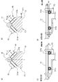
- FIG. 12A is a perspective view showing a lens holding frame F3 according to another example of the first embodiment
- FIG. 12B is a side view of the lens holding frame F3 according to another example of the first embodiment
- is. 13 is a cross-sectional view taken along the line DD of FIG. 12(B).
- the illustration of the configuration other than the third bearing 351 in the configuration of the biasing mechanism 35A is omitted.
- a fifth bearing 311c is provided as the bearing 311 in the modified example of the first embodiment.
- Two fifth bearings 311c are provided along the optical axis OA direction. Note that the number of the fifth bearings 311c may be three or more.
- the fifth bearing 311c is provided so as to face the third bearing 351 with the guide bar 22 interposed therebetween. As shown in FIG. 13, the fifth bearing 311c has a bearing portion 311c1 and an annular portion 311c2.
- the bearing portion 311c1 is press-fitted into a bearing support portion 316 formed in the first support portion 31.
- the annular portion 311c2 is an annular member. The inner peripheral surface of the annular portion 311c2 and the outer ring of the bearing portion 311c1 are fitted.
- the outer peripheral surface of the annular portion 311c2 is formed with a groove G1 that abuts on the guide bar 22 at two points (CP3, CP4).
- the groove G1 is substantially V-shaped. Note that the shape of the groove G1 is not limited to the V shape, and may be any shape as long as the guide bar 22 and the annular portion 311c2 are in contact with each other at two points.
- the contact point CP3 corresponds to the contact point CP1 (see FIG. 5) at which the first bearing 311a and the guide bar 22 described in the first embodiment abut, and the contact point CP4 corresponds to the first embodiment. It corresponds to the abutment point CP2 at which the second bearing 311b and the guide bar 22 abut as described in the embodiment.
- the number of bearings can be reduced more than in the first embodiment, so the structure of the lens holding frame F3 can be simplified. Further, as shown in FIG. 13, by arranging the third bearing 351 and the fifth bearing 311c so as to face each other with the guide bar 22 interposed therebetween, the lens holding frame F3 can be miniaturized.
- the third bearing 351 and the fifth bearing 311c do not necessarily have to face each other. Also, the arrangement positions of the third bearing 351 and the fifth bearing 311c may be reversed from those in FIG. That is, the third bearing 351 may be arranged between the lens holding frame F3 and the guide bar 22, and the fifth bearing 311c may be arranged on the outer peripheral side of the guide bar 22. FIG.
- a guide bar 22 made of a magnet or a ferromagnetic material and a magnet 356 that attracts the guide bar 22 are used to provide the first bearing 311a and the second bearing 311a. 311b is pressed against the guide bar 22, the lens holding frame F3 is biased against the guide bar 22;
- FIG. 14A is a perspective view showing the lens holding frame F3 according to the second embodiment
- FIG. 14B is a cross-sectional view of the lens holding frame F3 according to the second embodiment
- FIG. C) is a sectional view taken along line CC in FIG. 14(B).
- the guide bar 22 is made of magnet or ferromagnetic material.
- a magnet 356 that attracts the guide bar 22 is fixed at a position facing the guide bar 22 of the lens holding frame F3.
- the magnet 356 is arranged between the first bearing 311a and the second bearing 311b in the circumferential direction around the central axis AX1 of the guide bar 22.
- the magnet 356 Since the guide bar 22 is fixed to the second fixed barrel 20, the magnet 356 is attracted to the guide bar 22, and the lens holding frame F3 moves toward the guide bar 22 (direction indicated by arrow A31 in FIG. 14B). energized.
- the first bearing 311a and the second bearing 311b are pressed against the guide bar 22, and play between the guide bar 22 and the first bearing 311a and the second bearing 311b is suppressed. . Since other configurations are the same as those of the first embodiment, detailed description thereof will be omitted. Since the biasing mechanism 35A is not required in the second embodiment, it is possible to reduce the size. In addition, since the number of bearings is reduced (there is no third bearing 351 in contact with the guide bar 22), sliding noise and sliding resistance can be reduced.
- the lens holding frame F3 is biased toward the guide bar 22 by attracting the magnet 356 to the guide bar 22 made of a magnet or ferromagnetic material.
- the magnet 356 is not limited to this.
- the rotation regulating bar 23 may be made of a magnet, and the magnet may be arranged in a portion of the second support portion 32 facing the rotation regulating bar 23 so as to repel the rotation regulating bar 23, thereby allowing the lens holding frame F3 to move toward the guide bar. 22 may be biased.
- the second support portion 32 is provided with a biasing mechanism that biases the lens holding frame F3 against the guide bar 22 .
- FIG. 15A is a schematic perspective view of the lens holding frame F3 according to the third embodiment
- FIG. 15B is a cross-sectional view of the vicinity of the second support portion 32 of the lens holding frame F3 according to the third embodiment. be.
- a biasing mechanism 35C is provided on the second support portion 32.
- the biasing mechanism 35C includes a third bearing 351, a bearing support portion 352 that supports the third bearing 351, the second support portion 32 of the lens holding frame F3, and the bearing support portion 352. and a compression spring 353 disposed between.
- the bearing support portion 352 does not have the column member 352c
- the compression spring 353 is arranged in the hole 323 formed in the second support portion 32, and one end is connected to the second support portion 32. The other end is in contact with the bearing support portion 352 .
- the bearing support portion 352 is not fixed to the lens holding frame F3, but as in the first embodiment, when the lens holding frame F3 moves in the optical axis OA direction, the bearing support portion 352 also moves in the optical axis OA direction. move to
- a compression spring 353 is arranged between the second support portion 32 and the bearing support portion 352 .
- a compression spring 353 urges the third bearing 351 toward the rotation restricting bar 23 via the bearing support portion 352 . More specifically, the compression spring 353 urges the bearing support portion 352 toward the rotation restricting bar 23 (in the direction indicated by arrow A41 in FIG. 15B).
- the third bearing 351 is also urged toward the rotation restricting bar 23 (see arrow A42 in FIG. 15B) and pressed against the rotation restricting bar 23 .
- the lens holding frame F3 is biased toward the guide bar 22 (see arrow A43 in FIG. 15B).
- the first bearing 311a and the second bearing 311b are pressed against the guide bar 22, and play between the guide bar 22 and the first bearing 311a and the second bearing 311b is suppressed.
- the compression spring 353 for example, a torsion spring, a leaf spring, or an elastic body such as rubber may be used.
- FIG. 16(A) is a diagram for explaining the arrangement of the first bearing 311a, the second bearing 311b, and the third bearing 351
- FIG. 16(B) is a sectional view near the guide bar 22.
- the cross section of FIG. 16B corresponds to the AA line cross section of FIG.
- hatching representing cross sections of the guide bar 22 and the first support portion 31 is omitted.
- a virtual line VL1 in a direction D5 opposite to the biasing direction D4 of the third bearing 351 intersects the guide bar 22.
- the intersection IP1 closer to the third bearing 351 is located between the first bearing 311a and the guide. It is positioned between a position (CP1) where the bar 22 abuts and a position (CP2) where the second bearing 311b and the guide bar 22 abut. In this case, as shown in FIG.
- the angle ⁇ between the direction D5 and the direction D1 in which the first bearing 311a contacts the guide bar 22, the direction D5, and the second bearing 311b is preferable that the direction D2 in contact with the guide bar 22 and the angle ⁇ formed therebetween are substantially equal.
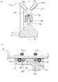
- the second support portion 32 is provided with a backlash suppressing mechanism 36 that suppresses backlash between the rotation restricting bar 23 and the fourth bearing 321 in addition to the biasing mechanism 35C.
- FIG. 17 is a diagram for explaining the configuration of the backlash suppressing mechanism 36. As shown in FIG.
- the backlash suppressing mechanism 36 includes a support portion 361 that is fixed to the second support portion 32 and supports one side of the fourth bearing 321 and the other side of the fourth bearing 321 toward the guide bar 22 .
- a biasing compression spring 362 is provided.
- the other side of the fourth bearing 321 is supported by a protrusion 322 protruding from the second support section 32 to the outer periphery, and the protrusion 322 has flexibility.
- One end of the compression spring 362 is connected to the support portion 361 and the other end is connected to the projecting portion 322 .
- the protrusion 322 bends toward the guide bar 22, and as a result, one side of the fourth bearing 321 is pressed against the rotation restricting bar 23 (in the direction indicated by arrow A35 in FIG. 17). Thereby, play between the rotation restricting bar 23 and the fourth bearing 321 can be suppressed.
- backlash suppressing mechanism 36 may be applied to the first embodiment and the second embodiment. Further, in the third embodiment, the backlash suppressing mechanism 36 is not provided in the second support portion 32, and the guide bar 22 is sandwiched without biasing the fourth bearing 321 as in the first and second embodiments. You may do so.
- the first bearings 311a and the second bearings 311b are alternately arranged along the optical axis OA direction. is not limited to
- FIG. 18A is a perspective view of a lens holding frame F3 according to a modification
- FIG. 18B is a view of the lens holding frame F3 in FIG. .
- the first bearing 311a and the second bearing 311b are arranged at substantially the same position in the optical axis OA direction.
- the first bearing 311a and the second bearing 311b are each press-fitted into a bearing support portion 316 formed in the first support portion 31.
- the eccentric mechanism 40 may not be provided.
- the positions of the central axes of the first bearing 311a and the second bearing 311b cannot be changed with respect to the lens holding frame F3.
- shift adjustment and tilt adjustment of the lens holding frame F3 can be performed.
- tilt adjustment may be performed by tilting the guide bar.
- the guide bar 22 and the magnet 356 made of a ferromagnetic material may be used as in the second embodiment, or the biasing mechanism of the third embodiment may be used. 35C may be used.
- the second fixed barrel 20 that houses the lens holding frame F3 may be a movable barrel that can move straight along the optical axis OA.
- the lens barrel 100 may be a single focus lens or a zoom lens.
Landscapes
- Physics & Mathematics (AREA)
- General Physics & Mathematics (AREA)
- Optics & Photonics (AREA)
- Lens Barrels (AREA)
Abstract
良好な光学性能を有するレンズ鏡筒を提供するため、レンズ鏡筒は、レンズを保持するレンズ保持枠(30)と、前記レンズ保持枠を光軸方向に案内する案内軸(22)と、前記レンズ保持枠(30)に支持され、前記案内軸(22)と当接する複数の当接部(311、351)と、前記複数の当接部(311、351)が前記案内軸(22)に押し付けられるように、前記レンズ保持枠(30)を前記案内軸(22)に対して付勢する付勢機構(353)と、を備える。
Description
レンズ鏡筒および撮像装置に関する。
レンズ鏡筒には、良好な光学性能が求められている(例えば、特許文献1)。
第1の態様によれば、レンズ鏡筒は、レンズを保持するレンズ保持枠と、前記レンズ保持枠を光軸方向に案内する案内軸と、前記レンズ保持枠に支持され、前記案内軸と当接する複数の当接部と、前記複数の当接部が前記案内軸に押し付けられるように、前記レンズ保持枠を前記案内軸に対して付勢する付勢機構と、を備える。
第2の態様によれば、撮像装置は、上記レンズ鏡筒と、撮像素子と、を備える。
なお、後述の実施形態の構成を適宜改良しても良く、また、少なくとも一部を他の構成物に代替させても良い。更に、その配置について特に限定のない構成要件は、実施形態で開示した配置に限らず、その機能を達成できる位置に配置することができる。
《第1実施形態》
以下、第1実施形態に係るレンズ鏡筒100について、図面を参照し、詳細に説明する。なお、各図において、理解を容易にするため、一部の要素の図示を省略している場合がある。
以下、第1実施形態に係るレンズ鏡筒100について、図面を参照し、詳細に説明する。なお、各図において、理解を容易にするため、一部の要素の図示を省略している場合がある。
図1は、第1実施形態に係るレンズ鏡筒100と、カメラ本体101と、を備えるカメラ1を示す図である。なお、本実施形態において、レンズ鏡筒100は、カメラ本体101に対して着脱可能であるが、これに限定されず、レンズ鏡筒100とカメラ本体101とは一体であってもよい。
カメラ本体101は、内部に撮像素子および制御部等を備えている。撮像素子は、たとえばCCD(Charge Coupled Device)等の光電変換素子によって構成され、結像光学系(カメラ本体101に装着されたレンズ鏡筒100)によって結像された被写体像を電気信号に変換する。
制御部は、CPU(Central Processing Unit)等を備え、カメラ本体101および装着されたレンズ鏡筒100における合焦駆動を含む撮影に係る当該カメラ1全体の動作を統括制御する。
図1に示すように、レンズ鏡筒100は、第1固定筒10と、第2固定筒20と、を備える。本実施形態において、第1固定筒10は複数の部品から構成されているが、1つの部品により構成されてもよい。図1に示すように、第1固定筒10には、レンズ鏡筒100をカメラ本体101に着脱可能とするレンズマウントLMが固定されている。
また、レンズ鏡筒100は、共通の光軸OAに沿って順次配列された第1~第7レンズ群L1~L7を備える。第3レンズ群L3はレンズ保持枠F3に保持され、その他のレンズ群は第1固定筒10に保持されている。なお、第1~第7レンズ群L1~L7は、それぞれ、複数のレンズで構成されていてもよい。また、第1、第2、第4~第7レンズ群L1,L2,L4~L7は、第1固定筒10ではなく、光軸OA方向に移動可能なレンズ保持枠に保持されていてもよい。
図2(A)は、第2固定筒20の構成を示す斜視図である。図1および図2(A)に示すように、第2固定筒20には、ガイドバー22および回転規制バー23が固定されている。ガイドバー22は、レンズ保持枠F3を光軸方向に案内する。回転規制バー23は、ガイドバー22を軸とするレンズ保持枠F3の回転を規制する。
また、図2(A)に示すように、第2固定筒20内には、レンズ保持枠F3を光軸OA方向に移動するためのボイスコイルモータ(VCM:Voice Coil Motor)50が設けられている。本実施形態では、VCM50は、第2固定筒20内の2か所に設けられているが、VCM50の数は本実施形態に限られるものではなく、1個でもよいし、3個以上でもよい。
図2(B)は、VCM50の概略構成を示す図である。VCM50は、光軸OA方向に長さを有する第1サイドヨーク501aおよび第2サイドヨーク501bと、光軸OA方向に長さを有し、第1サイドヨーク501aおよび第2サイドヨーク501bの間に配置されるセンターヨーク502と、を備える。
また、VCM50は、第1サイドヨーク501a、第2サイドヨーク501b、およびセンターヨーク502の光軸OA方向における一端を接続する上ヨーク503aと、第1サイドヨーク501a、第2サイドヨーク501b、およびセンターヨーク502の光軸OA方向における他端を接続する下ヨーク503bとを備える。これにより、閉磁路が形成される。
第1サイドヨーク501aのセンターヨーク502側の側面には第1磁石504aが配置され、第2サイドヨーク501bのセンターヨーク502側の側面には第2磁石504bが配置されている。第1磁石504aは、例えば、センターヨーク502側がN極となるように配置されており、第2磁石504bも、センターヨーク502側がN極となるように配置されている。これにより、磁束が第1磁石504aおよび第2磁石504bのN極からセンターヨーク502に入り、上ヨーク503aおよび下ヨーク503b並びに第1サイドヨーク501aおよび第2サイドヨーク501bを経て、第1磁石504aおよび第2磁石504bのS極にそれぞれ戻る磁路を形成している。
また、VCM50は、センターヨーク502に貫通されるコイル505を備える。コイル505の内周面とセンターヨーク502との間には僅かな隙間があり、コイル505は、光軸OA方向に移動可能となっている。またコイル505は、第1サイドヨーク501aおよび第2サイドヨーク501bからセンターヨーク502に集まる磁束の向きが、コイル505の巻き方向に垂直となるように構成されている。
コイル505には、駆動信号(電流)が入力される。コイル505に電流が流れると、第1磁石504aおよび第2磁石504bの磁力によりコイル505は光軸OA方向に移動する。より詳細には、電流が流れているコイル505と第1磁石504aおよび第2磁石504bとの間の電磁相互作用によりコイル505は光軸OA方向に移動する。コイル505に流す電流の向きを変更することで、コイル505の移動方向を被写体側とカメラ本体101側(像面側)との間で切り替えることができる。また、コイル505に流す電流値を変更することで、コイル505の駆動力や移動速度を変更することができる。
本実施形態において、第3レンズ群L3は、フォーカスレンズ群であって、VCM50によって光軸OA方向に移動されて、焦点調節を行う。より具体的には、第3レンズ群L3を保持するレンズ保持枠F3がVCM50のコイル505と連結されているため、コイル505が光軸OA方向に移動すると、第3レンズ群L3が光軸OA方向に移動される。なお、VCM50に代えて、ステッピングモータ、超音波モータを用いて第3レンズ群L3を移動させてもよい。
次に、レンズ保持枠F3の構成について説明する。図3(A)は、レンズ保持枠F3の概略斜視図であり、図3(B)は、図3(A)においてレンズ保持枠F3を矢印A1の方向から見た図である。図4は、レンズ保持枠F3の第1支持部31付近の断面図である。図5は、図4におけるA-A線断面図であり、図6は、図5において第1支持部31付近を拡大した断面図である。なお、図5では、第1支持部31およびガイドバー22の断面を示すハッチングを省略し、図6では、ガイドバー22の断面を示すハッチングを省略している。
図3(A)に示すように、レンズ保持枠F3は第3レンズ群L3を保持する筒部30を有し、筒部30の外周部には、ガイドバー22と当接する複数のベアリング311を支持する第1支持部31と、後述する第4ベアリング321を支持する第2支持部32と、VCM50のコイル505(図2(B)参照)を保持する保持部33と、が設けられている。保持部33は、VCM50の数(2つ)に合わせて、2か所に設けられている。
複数のベアリング311は、第1ベアリング311aと、第2ベアリング311bと、を有する。本第1実施形態において、第1ベアリング311aおよび第2ベアリング311bは、それぞれ2個ずつ設けられている。なお、以下の説明において、第1ベアリング311aと、第2ベアリング311bと、を特に区別する必要がない場合には、ベアリング311と記載する。
図6に示すように、第1ベアリング311aがガイドバー22に当接する方向(矢印A14で示す方向)と、第2ベアリング311bがガイドバー22に当接する方向(矢印A15で示す方向)とは、所定の角度αをなす。言い換えると、第1ベアリング311aがガイドバー22に当接する方向と、第2ベアリング311bがガイドバー22に当接する方向とは、交差する。さらに言い換えると、ガイドバー22の中心軸AX1を中心とする周方向において、第1ベアリング311aとガイドバー22とが当接する位置と、第2ベアリング311bとガイドバー22とが当接する位置とは、異なる。なお、所定の角度αは、例えば、0°より大きく180°より小さい。後述する圧縮ばね353の力を第1ベアリング311aおよび第2ベアリング311bに効率よく分配する観点から、所定の角度αは30°以上、120°以下が好ましい。
また、図5に示すように、光軸OAを中心とする円の径方向において、第1ベアリング311aとガイドバー22とが当接する当接点CP1と、第2ベアリング311bとガイドバー22とが当接する当接点CP2と、は、ガイドバー22の中心軸AX1よりも内周側に位置する。言い換えると、図5に示すように、光軸OAと直交し当接点CP1を含む平面において、ガイドバー22の中心軸AX1と光軸OAとを結ぶ直線は、当接点CP1と光軸OAとを結ぶ直線LN1よりも長い。また、光軸OAと直交し当接点CP2を含む平面において、ガイドバー22の中心軸AX1と光軸OAとを結ぶ直線は、当接点CP2と光軸OAとを結ぶ直線LN2よりも長い。これにより、光軸OAを中心とする円の径方向において、当接点CP1および当接点CP2が、ガイドバー22の中心軸AX1よりも外周側に位置する場合と比較して、レンズ鏡筒100を径方向に小型化できる。
本第1実施形態では、第1ベアリング311aおよび第2ベアリング311bがガイドバー22に押し付けられるように、レンズ保持枠F3をガイドバー22に対して付勢する付勢機構35Aが第1支持部31に取り付けられている。
図7(A)は付勢機構35Aの斜視図であり、図7(B)は、ベアリング支持部352の断面図である。付勢機構35Aは、図4および図7(A)に示すように、ガイドバー22と当接する第3ベアリング351と、第3ベアリング351を支持するベアリング支持部352と、備える。
ベアリング支持部352は、図7(A)および図7(B)に示すように、第3ベアリング351が突出する穴部352eを有し、光軸OA方向に延びる底部352aと、底部352aの短手方向の両端に設けられ、底部352aと略直交する一対の壁部352bと、後述する圧縮ばね353を取り付ける柱部材352cと、を備える。また、ベアリング支持部352は、図7(B)に示すように、第3ベアリング351の内輪の内周面と嵌合する嵌合部352dを備える。ベアリング支持部352は、レンズ保持枠F3に固定されていない。言い換えると、ベアリング支持部352は、レンズ保持枠F3に対して移動可能である。
また、付勢機構35Aは、図3(A)、図6、および図7(A)に示すように、ベアリング支持部352と対向する対向部354aと、対向部354aとレンズ保持枠F3とを連結する一対の連結部354bと、を有する固定部354を備える。固定部354の連結部354bは、図3(A)及び図3(B)に示すように、ビス355等によりレンズ保持枠F3に連結されている。
さらに、付勢機構35Aは、対向部354aに接触し、第3ベアリング351をガイドバー22に向けて付勢する圧縮ばね353を備える。圧縮ばね353は、ベアリング支持部352の柱部材352cに取り付けられる。圧縮ばね353の高さは、柱部材352cの高さよりも高くなっている。これにより、固定部354の対向部354aが、ベアリング支持部352の柱部材352cを覆うように、ベアリング支持部352および固定部354を配置することで、圧縮ばね353の一端が対向部354aと接触し、他端がベアリング支持部352の底部352aに接触する。これにより、固定部354がレンズ保持枠F3と共に光軸OA方向に移動すると、ベアリング支持部352も固定部354と共に光軸OA方向に移動する。なお、柱部材352cをベアリング支持部352ではなく、固定部354に設けてもよい。
圧縮ばね353は、ベアリング支持部352をガイドバー22に向けて(図4において矢印A11で示す方向)付勢する。これにより、ベアリング支持部352に支持された第3ベアリング351も、ガイドバー22に向けて付勢され(図4及び図6の矢印A12参照)、ガイドバー22に押し付けられる。また、圧縮ばね353は、固定部354をガイドバー22とは反対方向(図4において矢印A16で示す方向)に向けて付勢する。これにより、固定部354と連結しているレンズ保持枠F3が、ガイドバー22に向かって付勢され(図4及び図6の矢印A13参照)、第1ベアリング311aおよび第2ベアリング311bがガイドバー22に押し付けられる(図6の矢印A14およびA15参照)。これにより、ガイドバー22と第1ベアリング311a、第2ベアリング311bおよび第3ベアリング351との間のガタが抑制される。また、ガイドバー22とレンズ保持枠F3との間のガタが抑制される。なお、圧縮ばね353に代えて、例えばねじりバネ、板バネ、またはゴムのような弾性体を用いてもよい。
次に、第1ベアリング311aおよび第2ベアリング311bと、付勢機構35Aの第3ベアリング351と、の配置について説明する。図6に示すように、第3ベアリング351は、第3ベアリング351の付勢方向(矢印A12で示す方向)の仮想線VL2とガイドバー22の外周面との交点のうち、第3ベアリング351から遠い方の交点IP11が、ガイドバー22の中心軸AX1を中心とする周方向において、ガイドバー22と第1ベアリング311aとの当接点CP1と、ガイドバー22と第2ベアリング311bとの当接点CP2と、の間に位置するよう配置される。この場合、第1ベアリング311aがガイドバー22に当接する方向(矢印A14で示す方向)と、第3ベアリング351の付勢方向(矢印A12で示す方向)と、がなす角βと、第2ベアリング311bがガイドバー22に当接する方向(矢印A15で示す方向)と、第3ベアリング351の付勢方向(矢印A12で示す方向)と、がなす角γとは略等しい。このようにすることで、第1ベアリング311aおよび第2ベアリング311bを、バランス良くガイドバー22に押し付けることができる。なお、第1ベアリング311aおよび第2ベアリング311bがガイドバー22に押し付けられていれば、角βと角γとは等しくなくても良い。
レンズ保持枠F3の構成について、さらに説明する。図4に示すように、レンズ保持枠F3は、ガイドバー22と係合する係合部312a,312bを有する。係合部312a,312bはそれぞれ、ガイドバー22が挿通される穴320a,320bを有する。
穴320aの直径は、ガイドバー22の直径よりも大きく、穴320aの内周面は、ガイドバー22の外周面と接触しない。すなわち、レンズ保持枠F3は、ガイドバー22と接触しない。これにより、レンズ保持枠F3が光軸OA方向に移動するときに、レンズ保持枠F3の係合部312a、312bとガイドバー22との間に摩擦力が発生しないため、VCM50にかかる負荷を、レンズ保持枠F3がガイドバー22と接触する場合と比較して小さくすることができる。また、ガイドバー22が係合部312a,312bの穴320a,320bに挿通されているので、レンズ鏡筒100に衝撃が与えられた場合であっても、レンズ保持枠F3がガイドバー22から外れて、第2固定筒20に衝突する等の事態を防ぐことができる。
次に、第1ベアリング311aおよび第2ベアリング311bを支持する構成について説明する。本第1実施形態では、第1ベアリング311aおよび第2ベアリング311bは、偏心機構40を介して、レンズ保持枠F3に支持されている。偏心機構40は、第1ベアリング311aおよび第2ベアリング311bの回転軸の位置をレンズ保持枠F3に対して変更するための機構である。
図8(A)は、偏心機構40の構成を説明するための斜視図であり、図8(B)は、偏心機構40が備える偏心部41の平面図であり、図8(C)は、偏心機構40が備える固定部42の斜視図である。なお、図8(A)では、付勢機構35Aの図示を省略している。
偏心機構40は、図8(A)に示すように、偏心部41と固定部42とを備える。偏心部41は、図8(B)に示すように、略環状であって、内周面の中心C2が外周面の中心C1に対してずれている(偏心している)。
図8(C)に示すように、固定部42は、ベアリング311の内輪の内周面および偏心部41の内周面401と嵌合する嵌合部421を有する。嵌合部421と偏心部41の内周面401とが嵌合することで、ベアリング311は、偏心部41に固定される。このとき、ベアリング311の中心軸(回転軸)は、偏心部41の内周面の中心C2と略一致する。
偏心部41は、図8(A)に示すように、第1支持部31に形成された穴315の内壁と嵌合する。偏心部41を穴315内に配置し、例えば、ビス45等を用いて、偏心機構40を第1支持部31に固定する。これにより、ベアリング311はレンズ保持枠F3に支持される。
上述したように、偏心部41では、内周面401の中心C2が外周面の中心C1に対して偏心しているので、偏心部41を穴315内で回転させる(偏心部41の外周面の中心C1を軸として回転させる)と、内周面の中心C2の移動軌跡は、図8(B)に点線で示す軌跡T1となる。
例えば、図9(A)において、レンズ保持枠F3の第1支持部31の上端と、偏心部41の内周面401の中心C2との距離がd11であったとする。ここで、偏心部41を穴315内において、矢印A51で示す方向に90度回転させる。この場合、図9(B)に示すように、第1支持部31の上端と、偏心部41の内周面401の中心C2との距離はd12(<d11)となる。ベアリング311の中心軸は、偏心部41の内周面の中心C2と略一致しているため、偏心部41を回転させることで、第1支持部31の上端とベアリング311の中心軸との距離を変更することができる。すなわち、偏心機構40を用いて、ベアリング311の中心軸の第1支持部31(レンズ保持枠F3)に対する位置を変更することができる。
第1ベアリング311aおよび第2ベアリング311bの中心軸の第1支持部31に対する位置を変更することで、光軸OAと直交する平面における第3レンズ群L3の中心軸の位置、および光軸OAに対する第3レンズ群L3の中心軸の傾きを調整することができる。この点について、詳細に説明する。
図10(A)及び図10(B)は、光軸OAと直交する平面における第3レンズ群L3の中心軸の位置の調整(シフト調整ともいう)について説明する図である。図10(A)及び図10(B)に示すように、全ての第2ベアリング311bについて、第2ベアリング311bと第1支持部31の上端との距離がd1からd2(d1>d2)となるように、偏心部41を回転させることによって、第2ベアリング311bの中心軸の位置を変更する。これにより、レンズ保持枠F3は、矢印A21で示すように、右側にシフトするため、第3レンズ群L3の中心軸も右側にシフトする。このように、偏心機構40によって第1ベアリング311aおよび第2ベアリング311bの中心軸の第1支持部31に対する位置を変更することで、光軸OAと直交する平面における第3レンズ群L3の中心軸の位置を変更することができる。
図10(C)及び図10(D)は、光軸OAに対する第3レンズ群L3の中心軸の傾きの調整(チルト調整ともいう)について説明する図である。図10(C)に示すように、2つの第2ベアリング311bにおいて、第2ベアリング311bの中心軸と第1支持部31の上端との距離がd3に設定されているとする。このとき、像面側の第2ベアリング311bにおいて、第2ベアリング311bの中心軸と第1支持部31の上端との距離をd3としたままとする。被写体側の第2ベアリング311bでは、図10(D)に示すように、第2ベアリング311bの中心軸と第1支持部31の上端との距離がd3からd4(d3>d4)となるように、偏心部41を回転させることによって、第2ベアリング311bの中心軸の位置を変更する。第1ベアリング311aについても同様に、像面側の第1ベアリング311aの中心軸と第1支持部31の上端との距離をd3のままとし、被写体側の第1ベアリング311aでは、第1ベアリング311aの中心軸と第1支持部31の上端との距離をd4(<d3)となるようにする。これにより、レンズ保持枠F3は、図10(D)に示すように傾くため、レンズ保持枠F3が保持する第3レンズ群L3の中心軸も傾く。このように、偏心機構40を用いて、光軸OAに対する第3レンズ群L3の中心軸の傾きを調整することができる。
図3(A)に戻り、第2支持部32には、回転規制バー23を挟み込むように第4ベアリング321が設けられている。これにより、ガイドバー22を軸とするレンズ保持枠F3の回転を規制することができる。また、回転規制バー23と第2支持部32とが接触する場合と比較して、回転規制バー23との間の摩擦抵抗を低減することができ、VCM50にかかる負荷を低減することができる。
以上、詳細に説明したように、本第1実施形態によれば、レンズ鏡筒100は、第3レンズ群L3を保持するレンズ保持枠F3と、レンズ保持枠F3を光軸OA方向に案内するガイドバー22と、レンズ保持枠F3に支持され、ガイドバー22と当接する複数のベアリング311と、ベアリング311がガイドバー22に押し付けられるように、レンズ保持枠F3をガイドバー22に対して付勢する付勢機構35Aと、を備える。付勢機構35Aにより、複数のベアリング311がガイドバー22に押し付けられるので、ガイドバー22と複数のベアリング311との間のガタを抑制することができる。これにより、ガイドバー22とレンズ保持枠F3とのガタが抑制され、レンズ保持枠F3をガタ付きなく光軸OA方向に案内できる。また、レンズ保持枠F3が光軸OA方向に移動するときのガイドバー22との間の摩擦抵抗を低減させることができる。
また、本第1実施形態において、ガイドバー22の中心軸AX1を中心とする周方向において、第1ベアリング311aとガイドバー22とが当接する位置と、第2ベアリング311bとが当接する位置とは、異なる(図6参照)。これにより、第1ベアリング311aおよび第2ベアリング311bとガイドバー22との間のガタを抑制できるとともに、ガイドバー22に対するレンズ保持枠F3の位置決めを行うことができる。
また、本第1実施形態において、光軸OAを中心とする円の径方向において、第1ベアリング311aとガイドバー22とが当接する当接点CP1および第2ベアリング311bとガイドバー22とが当接する当接点CP2は、ガイドバー22の中心軸AX1よりも内周側に位置する。これにより、レンズ鏡筒100の径方向のサイズを小型化することができる。
また、本第1実施形態において、レンズ保持枠F3とガイドバー22とは、接触しない。レンズ保持枠F3がガイドバー22に案内されて光軸OA方向に移動するとき、ガイドバー22に接触するのはベアリング311および第3ベアリング351であるため、ガイドバー22との間の摩擦抵抗を低減でき、VCM50にかかる負荷を小さくすることができる。
また、本第1実施形態において、レンズ保持枠F3は、ガイドバー22が挿通される穴320a,320bを有し、穴320a,320bの直径は、ガイドバー22の直径よりも大きい。これにより、レンズ保持枠F3がガイドバー22に案内されて光軸OA方向に移動するときのガイドバー22との間の摩擦抵抗を低減でき、VCM50にかかる負荷を低減することができる。また、レンズ鏡筒100に衝撃が加わった場合に、レンズ保持枠F3がガイドバー22から外れて第2固定筒20の内壁に衝突する等の事態を防ぐことができる。
また、本第1実施形態において、レンズ鏡筒100は、第1ベアリング311aおよび第2ベアリング311bの中心軸のレンズ保持枠F3に対する位置を変化させる偏心機構40を備える。これにより、光軸OAと直交する平面における第3レンズ群L3の中心軸の位置、および光軸OAに対する第3レンズ群L3の中心軸の傾きを調整することができる。なお、偏心機構40は、ベアリング311の全てに対して設けなくてもよい。偏心機構40を、ベアリング311のうちの少なくとも1つに設け、他のベアリング311については、例えば、樹脂製または金属製の環状部材を取り付けてベアリング311の外径を変更することで、チルト調整やシフト調整を行ってもよい。
また、本第1実施形態において、付勢機構35Aは、ガイドバー22と当接する第3ベアリング351と、ガイドバー22と対向する対向部354aを有し、レンズ保持枠F3に固定される固定部354と、対向部354aに接触し、第3ベアリング351をガイドバー22に向けて付勢する圧縮ばね353と、を備える。この場合において、第3ベアリング351の付勢方向の仮想線VL2と、ガイドバー22の外周との交点のうち、第3ベアリング351から遠い方の交点IP11は、ガイドバー22の中心軸を中心とする周方向において、第1ベアリング311aとガイドバー22とが当接する位置(CP1)と、第2ベアリング311bとガイドバー22とが当接する位置(CP2)との間に位置する(図6参照)。これにより、レンズ保持枠F3に支持された第1ベアリング311aおよび第2ベアリング311bがガイドバー22に押し付けられるように、レンズ保持枠F3を付勢することができる。
なお、上記第1実施形態において、光軸OAを中心とする円の径方向において、図11(A)に示すように、第1ベアリング311aおよび第2ベアリング311bとガイドバー22とがそれぞれ当接する当接点CP1およびCP2が、ガイドバー22の中心軸AX1よりも外周側に位置するように第1ベアリング311aおよび第2ベアリング311bを配置してもよい。この場合、例えば、図11(A)に示すように、第3ベアリング351をガイドバー22とレンズ保持枠F3との間に配置し、図11(B)に示すように、圧縮ばね353をレンズ保持枠F3とベアリング支持部352との間に配置することで、第3ベアリング351をガイドバー22に向けて付勢してもよい。この場合において、ベアリング支持部352の柱部材352cをレンズ保持枠F3に設けてもよい。なお、第1ベアリング311aおよび第2ベアリング311bを支持する構造は、図11(A)および図11(B)に示す構造に限られるものではない。
なお、上記第1実施形態において、付勢機構35Aが有する第3ベアリング351の数は2個に限られるものではなく、1個でもよいし、3個以上であってもよい。また、付勢機構35Aが有する圧縮ばね353の数は2個に限られるものではなく、1個でもよいし、3個以上であってもよい。
また、上記第1実施形態において、第1ベアリング311aおよび第2ベアリング311bはそれぞれ2個ずつ設けられていたが、第1ベアリング311aおよび第2ベアリング311bはそれぞれ少なくとも1個ずつ設けられていればよい。また、第1ベアリング311aおよび第2ベアリング311bをそれぞれ3個以上設けてもよい。また、第1ベアリング311aの数と、第2ベアリング311bの数とは、同じでもよいし、異なっていてもよい。後述する第2実施形態、第3実施形態、およびその変形例においても同様である。
また、上記第1実施形態において、第1ベアリング311aおよび第2ベアリング311bそれぞれの機能を1つのベアリングで実現してもよい。図12(A)は、第1実施形態の別例に係るレンズ保持枠F3を示す斜視図であり、図12(B)は、第1実施形態の別例に係るレンズ保持枠F3の側面図である。また、図13は、図12(B)のD-D線断面図である。なお、図13において、付勢機構35Aの構成のうち、第3ベアリング351以外の構成の図示を省略している。
図12(A)及び図12(B)に示すように、第1実施形態の変形例では、第5ベアリング311cをベアリング311として設けている。第5ベアリング311cは、光軸OA方向に沿って2つ設けられている。なお、第5ベアリング311cの数は、3つ以上であってもよい。
第5ベアリング311cは、ガイドバー22をはさんで第3ベアリング351と対向するように設けられている。図13に示すように、第5ベアリング311cは、ベアリング部311c1と、円環部311c2と、を有する。
ベアリング部311c1は、第1支持部31に形成されたベアリング支持部316に圧入されている。
円環部311c2は、円環状の部材である。円環部311c2の内周面とベアリング部311c1の外輪とは嵌合している。
図13に示すように、円環部311c2の外周面には、ガイドバー22と2点(CP3、CP4)で当接するような溝G1が形成されている。本実施形態では、溝G1は略V字状となっている。なお、溝G1の形状は、V字状に限られるものではなく、ガイドバー22と円環部311c2とが2か所で接触するような形状であればよい。
図13において、当接点CP3が、上記第1実施形態で説明した第1ベアリング311aとガイドバー22とが当接する当接点CP1(図5参照)に対応し、当接点CP4が、上記第1実施形態で説明した第2ベアリング311bとガイドバー22とが当接する当接点CP2に対応する。
第1実施形態の別例に係るレンズ保持枠F3では、上記第1実施形態よりもベアリングの数を削減することができるので、レンズ保持枠F3の構造を簡素化することができる。また、図13に示すように、ガイドバー22を挟んで第3ベアリング351と第5ベアリング311cとを対向するように配置することで、レンズ保持枠F3を小型化することができる。
なお、第3ベアリング351と第5ベアリング311cとは、必ずしも対向していなくてもよい。また、第3ベアリング351と第5ベアリング311cの配置位置を図13とは逆にしてもよい。すなわち、第3ベアリング351をレンズ保持枠F3とガイドバー22との間に配置し、第5ベアリング311cをガイドバー22よりも外周側に配置してもよい。
《第2実施形態》
第2実施形態では、付勢機構35Aに代わって、磁石または強磁性体材料で構成されたガイドバー22と、ガイドバー22と引き合う磁石356と、を用いて、第1ベアリング311aおよび第2ベアリング311bがガイドバー22に対して押し付けられるように、レンズ保持枠F3をガイドバー22に対して付勢する。
第2実施形態では、付勢機構35Aに代わって、磁石または強磁性体材料で構成されたガイドバー22と、ガイドバー22と引き合う磁石356と、を用いて、第1ベアリング311aおよび第2ベアリング311bがガイドバー22に対して押し付けられるように、レンズ保持枠F3をガイドバー22に対して付勢する。
図14(A)は、第2実施形態に係るレンズ保持枠F3を示す斜視図であり、図14(B)は、第2実施形態に係るレンズ保持枠F3の断面図であり、図14(C)は、図14(B)におけるC-C線断面図である。
第2実施形態では、ガイドバー22は磁石または強磁性体材料で構成されている。図14(A)に示すように、レンズ保持枠F3のガイドバー22と対向する位置には、ガイドバー22と引き合う磁石356が固定されている。図14(C)に示すように、磁石356は、ガイドバー22の中心軸AX1を中心とする周方向において、第1ベアリング311aと第2ベアリング311bとの間に配置されている。
ガイドバー22は第2固定筒20に固定されているため、磁石356がガイドバー22に引き付けられ、レンズ保持枠F3はガイドバー22に向かって(図14(B)において矢印A31で示す方向)付勢される。
これにより、第1実施形態と同様に、第1ベアリング311aおよび第2ベアリング311bがガイドバー22に押し付けられ、ガイドバー22と第1ベアリング311aおよび第2ベアリング311bとの間のガタが抑制される。その他の構成は、第1実施形態と同様であるため、詳細な説明を省略する。第2実施形態では、付勢機構35Aが不要になる為、小型化が可能になる。また、ベアリング個数が減る(ガイドバー22と接触する第3ベアリング351がない)ため、摺動音や摺動抵抗を低減することができる。
なお、第2実施形態では、磁石または強磁性体材料で構成されるガイドバー22に、磁石356が引き付けられるようにすることで、レンズ保持枠F3をガイドバー22に向かって付勢していたが、これに限られるものではない。
例えば、回転規制バー23を磁石で構成し、第2支持部32の回転規制バー23と対向する部分に回転規制バー23と反発しあうように磁石を配置することでレンズ保持枠F3をガイドバー22に向かって付勢してもよい。
《第3実施形態》
第3実施形態では、ガイドバー22に対してレンズ保持枠F3を付勢する付勢機構を、第2支持部32に設ける。
第3実施形態では、ガイドバー22に対してレンズ保持枠F3を付勢する付勢機構を、第2支持部32に設ける。
図15(A)は、第3実施形態におけるレンズ保持枠F3の概略斜視図であり、図15(B)は、第3実施形態におけるレンズ保持枠F3の第2支持部32付近の断面図である。
図15(A)及び図15(B)に示すように、付勢機構35Cが、第2支持部32に設けられている。付勢機構35Cは、図15(B)に示すように、第3ベアリング351と、第3ベアリング351を支持するベアリング支持部352と、レンズ保持枠F3の第2支持部32とベアリング支持部352との間に配置される圧縮ばね353と、を備える。なお、付勢機構35Cでは、ベアリング支持部352は柱部材352cを備えておらず、圧縮ばね353は第2支持部32に形成された穴323内に配置され、一端が第2支持部32と接触し、他端がベアリング支持部352と接触している。これにより、ベアリング支持部352は、レンズ保持枠F3に固定されていないが、第1実施形態と同様に、レンズ保持枠F3が光軸OA方向に移動すると、ベアリング支持部352も光軸OA方向に移動する。
図15(B)に示すように、第2支持部32とベアリング支持部352との間には、圧縮ばね353が配置されている。圧縮ばね353は、ベアリング支持部352を介して第3ベアリング351を回転規制バー23に向けて付勢する。より詳細には、圧縮ばね353は、ベアリング支持部352を回転規制バー23に向けて(図15(B)において矢印A41で示す方向)付勢する。これにより、第3ベアリング351も、回転規制バー23に向けて付勢され(図15(B)の矢印A42参照)、回転規制バー23に押し付けられる。その結果、レンズ保持枠F3が、ガイドバー22に向かって付勢される(図15(B)の矢印A43参照)。これにより、第1実施形態で説明したように、第1ベアリング311aおよび第2ベアリング311bがガイドバー22に押し付けられ、ガイドバー22と第1ベアリング311aおよび第2ベアリング311bとの間のガタが抑制される。なお、圧縮ばね353に代えて、例えばねじりバネ、板バネ、またはゴムのような弾性体を用いてもよい。
次に、第1ベアリング311aおよび第2ベアリング311bと、第3ベアリング351との配置について説明する。図16(A)は、第1ベアリング311aおよび第2ベアリング311bと、第3ベアリング351との配置について説明するための図であり、図16(B)は、ガイドバー22付近の断面図である。図16(B)の断面は、図4のA-A線断面に相当する。なお、見易さのため、ガイドバー22と第1支持部31の断面を表すハッチングを省略している。
図16(A)に示すように、第3ベアリング351の付勢方向D4と逆の方向D5の仮想線VL1は、ガイドバー22と交差する。また、ガイドバー22の中心軸AX1を中心とする周方向において、仮想線VL1とガイドバー22の外周との交点のうち、第3ベアリング351に近い方の交点IP1は、第1ベアリング311aとガイドバー22とが当接する位置(CP1)と、第2ベアリング311bとガイドバー22とが当接する位置(CP2)との間に位置する。なお、この場合において、図16(B)に示すように、方向D5と、第1ベアリング311aがガイドバー22に当接する方向D1と、がなす角δと、方向D5と、第2ベアリング311bがガイドバー22に当接する方向D2と、がなす角εと、は略等しいことが好ましい。
本第3実施形態において、第2支持部32には、付勢機構35Cに加えて、回転規制バー23と第4ベアリング321との間のガタを抑制するガタ抑制機構36が設けられている。図17は、ガタ抑制機構36の構成について説明するための図である。
図17に示すように、ガタ抑制機構36は、第2支持部32に固定され、第4ベアリング321の一方を支持する支持部361と、第4ベアリング321の他方をガイドバー22に向けて付勢する圧縮ばね362を備える。
第4ベアリング321の他方は、第2支持部32から外周に突出する突部322に支持されており、突部322は可とう性を有する。圧縮ばね362の一端は、支持部361と連結され、他端は突部322に連結されている。これにより、突部322がガイドバー22に向かってたわみ、その結果、第4ベアリング321の一方が回転規制バー23に押し付けられる(図17の矢印A35で示す方向)。これにより、回転規制バー23と第4ベアリング321との間のガタを抑制できる。
なお、ガタ抑制機構36を第1実施形態および第2実施形態に適用してもよい。また、第3実施形態において、第2支持部32にガタ抑制機構36を設けず、第1実施形態および第2実施形態と同様に、第4ベアリング321を付勢せずにガイドバー22を挟み込むようにしてもよい。
(変形例)
上記第1~第3実施形態では、第1ベアリング311aと第2ベアリング311bとが光軸OA方向に沿って互い違いに配置されていたが、第1ベアリング311aおよび第2ベアリング311bの配置は、これに限られるものではない。
上記第1~第3実施形態では、第1ベアリング311aと第2ベアリング311bとが光軸OA方向に沿って互い違いに配置されていたが、第1ベアリング311aおよび第2ベアリング311bの配置は、これに限られるものではない。
図18(A)は、変形例に係るレンズ保持枠F3の斜視図であり、図18(B)は、図18(A)においてレンズ保持枠F3を矢印A51で示す方向から見た図である。
図18(B)に示すように、変形例において、第1ベアリング311aと第2ベアリング311bとは、光軸OA方向において略同じ位置に配置されている。
また、変形例において、第1ベアリング311aおよび第2ベアリング311bはそれぞれ、第1支持部31に形成されたベアリング支持部316に圧入されている。このように、偏心機構40を設けなくてもよい。この場合、第1ベアリング311aおよび第2ベアリング311bの中心軸の位置を、レンズ保持枠F3に対して変更することはできない。しかしながら、第1ベアリング311aおよび第2ベアリング311bの外周に、樹脂製または金属製の環状部材を取り付けて第1ベアリング311aおよび第2ベアリング311bの外径を変更することで、第1実施形態と同様に、レンズ保持枠F3のシフト調整およびチルト調整を行うことができる。また、ガイドバーを傾けることでチルト調整をしてもよい。
その他の構成は、第1実施形態と同様であるため、詳細な説明を省略する。なお、変形例において、付勢機構35Aに代えて、第2実施形態と同様に強磁性体材料から構成されるガイドバー22および磁石356を用いてもよいし、第3実施形態の付勢機構35Cを用いてもよい。
なお、上記第1~第3実施形態およびその変形例において、第1ベアリング311a、第2ベアリング311b、第3ベアリング351、及び第5ベアリング311cに代えて、ガイドバー22に当接する突起部を用いてもよい。
また、上記実施形態およびその変形例において、レンズ保持枠F3を収納する第2固定筒20は、光軸OA方向に直進移動が可能な移動筒であってもよい。また、上記実施形態およびその変形例において、レンズ鏡筒100は単焦点レンズであってもよいし、ズームレンズであってもよい。
上述した実施形態は好適な実施の例である。但し、これに限定されるものではなく、要旨を逸脱しない範囲内において種々変形実施可能であり、任意の構成要件を組み合わせてもよい。
1 カメラ
22 ガイドバー
23 回転規制バー
100 レンズ鏡筒
311 ベアリング
311a 第1ベアリング
311b 第2ベアリング
321 第4ベアリング
351 第3ベアリング
352 ベアリング支持部
353 圧縮ばね
354 固定部
354a 対向部
F3 レンズ保持枠
L3 第3レンズ群
22 ガイドバー
23 回転規制バー
100 レンズ鏡筒
311 ベアリング
311a 第1ベアリング
311b 第2ベアリング
321 第4ベアリング
351 第3ベアリング
352 ベアリング支持部
353 圧縮ばね
354 固定部
354a 対向部
F3 レンズ保持枠
L3 第3レンズ群
Claims (14)
- レンズを保持するレンズ保持枠と、
前記レンズ保持枠を光軸方向に案内する案内軸と、
前記レンズ保持枠に支持され、前記案内軸と当接する複数の当接部と、
前記複数の当接部が前記案内軸に押し付けられるように、前記レンズ保持枠を前記案内軸に対して付勢する付勢機構と、
を備えるレンズ鏡筒。 - 前記複数の当接部は、第1当接部と第2当接部とを有し、
前記第1当接部が前記案内軸に当接する方向と、前記第2当接部が前記案内軸に当接する方向と、は所定の角度をなす、
請求項1に記載のレンズ鏡筒。 - 前記複数の当接部は、第1当接部と第2当接部とを有し、
前記第1当接部が前記案内軸に当接する方向と、前記第2当接部が前記案内軸に当接する方向と、は交差する、
請求項1に記載のレンズ鏡筒。 - 前記複数の当接部は、第1当接部と第2当接部とを有し、
前記案内軸の中心軸を中心とする周方向において、前記第1当接部と前記案内軸とが当接する位置と、前記第2当接部と前記案内軸とが当接する位置とは、異なる、
請求項1に記載のレンズ鏡筒。 - 光軸と直交し前記複数の当接部と前記案内軸とが当接する当接点を含む各平面において、前記案内軸の中心軸と前記光軸とを結ぶ直線は、前記当接点と前記光軸とを結ぶ直線よりも長い、
請求項1から請求項4のいずれか1項記載のレンズ鏡筒。 - 光軸を中心とする円の径方向において、前記複数の当接部と前記案内軸とが当接する当接点は、前記案内軸の中心軸よりも内周側に位置する、
請求項1から請求項5のいずれか1項記載のレンズ鏡筒。 - 前記レンズ保持枠と前記案内軸とは接触しない、
請求項1から請求項6のいずれか1項記載のレンズ鏡筒。 - 前記レンズ保持枠は、前記案内軸が挿通される穴を有し、
前記穴の直径は、前記案内軸の直径よりも大きい、
請求項1から請求項7のいずれか1項記載のレンズ鏡筒。 - 前記複数の当接部のうち少なくとも1つの中心軸の前記レンズ保持枠に対する位置を変化させる、偏心機構を備える、
請求項1から請求項8のいずれか1項に記載のレンズ鏡筒。 - 前記付勢機構は、
前記案内軸と当接する第3当接部と、
前記第3当接部を支持する支持部と、
前記レンズ保持枠に固定される固定部と、
前記支持部と前記固定部との間に配置される付勢部と、
を備える請求項1から請求項9の何れか1項に記載のレンズ鏡筒。 - 前記第3当接部の付勢方向の仮想線と前記案内軸の外周との交点のうち前記第3当接部から遠い方の交点は、前記案内軸の中心軸を中心とする周方向において、前記複数の当接部の1つと前記案内軸とが当接する位置と、前記複数の当接部の他の1つと前記案内軸とが当接する位置との間に位置する、
請求項10に記載のレンズ鏡筒。 - 前記案内軸は、磁石または強磁性体材料から構成され、
前記レンズ保持枠は、前記案内軸と対向するように配置され、前記案内軸と引き付け合う磁石を備える、
請求項1から請求項9のいずれか1項記載のレンズ鏡筒。 - 前記レンズ保持枠の前記案内軸を軸とする回転を規制する規制軸を備え、
前記付勢機構は、
前記規制軸と当接する第3当接部と、
前記レンズ保持枠に接触し、前記第3当接部を前記規制軸に向けて付勢する付勢部と、
を有する、
請求項1から請求項9のいずれか1項記載のレンズ鏡筒。 - 請求項1から請求項13のいずれか1項に記載のレンズ鏡筒と、
撮像素子と、
を備える撮像装置。
Priority Applications (1)
| Application Number | Priority Date | Filing Date | Title |
|---|---|---|---|
| JP2023508635A JPWO2022201702A1 (ja) | 2021-03-22 | 2021-12-23 |
Applications Claiming Priority (2)
| Application Number | Priority Date | Filing Date | Title |
|---|---|---|---|
| JP2021047354 | 2021-03-22 | ||
| JP2021-047354 | 2021-03-22 |
Publications (1)
| Publication Number | Publication Date |
|---|---|
| WO2022201702A1 true WO2022201702A1 (ja) | 2022-09-29 |
Family
ID=83396763
Family Applications (1)
| Application Number | Title | Priority Date | Filing Date |
|---|---|---|---|
| PCT/JP2021/047843 WO2022201702A1 (ja) | 2021-03-22 | 2021-12-23 | レンズ鏡筒および撮像装置 |
Country Status (2)
| Country | Link |
|---|---|
| JP (1) | JPWO2022201702A1 (ja) |
| WO (1) | WO2022201702A1 (ja) |
Citations (9)
| Publication number | Priority date | Publication date | Assignee | Title |
|---|---|---|---|---|
| JPH0749443A (ja) * | 1993-04-12 | 1995-02-21 | Hughes Aircraft Co | ローラ案内部を備えた永久磁石サスペンション |
| WO2006035581A1 (ja) * | 2004-09-29 | 2006-04-06 | Kyocera Corporation | カメラモジュール及びこのカメラモジュールを用いた携帯端末 |
| JP2007232889A (ja) * | 2006-02-28 | 2007-09-13 | Chinontec Kk | レンズ鏡筒 |
| WO2011010470A1 (ja) * | 2009-07-23 | 2011-01-27 | パナソニック株式会社 | レンズ鏡筒および撮像装置 |
| JP2012078717A (ja) * | 2010-10-05 | 2012-04-19 | Olympus Imaging Corp | レンズ鏡筒 |
| JP2014202908A (ja) * | 2013-04-04 | 2014-10-27 | キヤノン株式会社 | 光学部材駆動装置および撮像装置 |
| JP2018200367A (ja) * | 2017-05-26 | 2018-12-20 | キヤノン株式会社 | レンズ装置 |
| JP2021131460A (ja) * | 2020-02-19 | 2021-09-09 | キヤノン株式会社 | 光学駆動装置および光学機器 |
| JP2021135428A (ja) * | 2020-02-28 | 2021-09-13 | キヤノン株式会社 | レンズ装置および撮像装置 |
-
2021
- 2021-12-23 JP JP2023508635A patent/JPWO2022201702A1/ja active Pending
- 2021-12-23 WO PCT/JP2021/047843 patent/WO2022201702A1/ja active Application Filing
Patent Citations (9)
| Publication number | Priority date | Publication date | Assignee | Title |
|---|---|---|---|---|
| JPH0749443A (ja) * | 1993-04-12 | 1995-02-21 | Hughes Aircraft Co | ローラ案内部を備えた永久磁石サスペンション |
| WO2006035581A1 (ja) * | 2004-09-29 | 2006-04-06 | Kyocera Corporation | カメラモジュール及びこのカメラモジュールを用いた携帯端末 |
| JP2007232889A (ja) * | 2006-02-28 | 2007-09-13 | Chinontec Kk | レンズ鏡筒 |
| WO2011010470A1 (ja) * | 2009-07-23 | 2011-01-27 | パナソニック株式会社 | レンズ鏡筒および撮像装置 |
| JP2012078717A (ja) * | 2010-10-05 | 2012-04-19 | Olympus Imaging Corp | レンズ鏡筒 |
| JP2014202908A (ja) * | 2013-04-04 | 2014-10-27 | キヤノン株式会社 | 光学部材駆動装置および撮像装置 |
| JP2018200367A (ja) * | 2017-05-26 | 2018-12-20 | キヤノン株式会社 | レンズ装置 |
| JP2021131460A (ja) * | 2020-02-19 | 2021-09-09 | キヤノン株式会社 | 光学駆動装置および光学機器 |
| JP2021135428A (ja) * | 2020-02-28 | 2021-09-13 | キヤノン株式会社 | レンズ装置および撮像装置 |
Also Published As
| Publication number | Publication date |
|---|---|
| JPWO2022201702A1 (ja) | 2022-09-29 |
Similar Documents
| Publication | Publication Date | Title |
|---|---|---|
| EP0469532B1 (en) | Optical apparatus provided with a driving unit for moving a lens | |
| KR101525816B1 (ko) | 상흔들림 보정 장치 | |
| US7623151B2 (en) | Vibration correcting device, lens barrel, and optical device | |
| JP4764075B2 (ja) | 像ぶれ補正装置、該像ぶれ補正装置を備えたレンズ鏡筒 | |
| US20110122495A1 (en) | Imaging lens unit and imaging apparatus | |
| KR102234859B1 (ko) | 흔들림 보정 기능을 가지는 카메라 장치 | |
| US7679225B2 (en) | Voice coil motors and pre-compression generation devices thereof | |
| US9063347B2 (en) | Imaging apparatus | |
| KR20150091017A (ko) | 촬상 장치 | |
| JP4602780B2 (ja) | 画像振れ防止装置 | |
| JP2006215122A5 (ja) | ||
| JP2024096911A (ja) | 手ブレ補正装置 | |
| WO2022201702A1 (ja) | レンズ鏡筒および撮像装置 | |
| JP3349808B2 (ja) | 光学素子駆動装置 | |
| KR20210041947A (ko) | 카메라 액추에이터 및 이를 포함하는 카메라 장치 | |
| JP2009150922A (ja) | アクチュエータ、撮像機器および携帯電子機器 | |
| JP6235388B2 (ja) | 撮像装置 | |
| JP2003098420A (ja) | 光学素子駆動装置 | |
| JP6120691B2 (ja) | 像振れ補正装置、光学機器、及び撮像装置 | |
| JP2019095627A (ja) | 防振レンズ鏡筒 | |
| JP6137879B2 (ja) | 像振れ補正装置、レンズ鏡筒、光学機器、および撮像装置 | |
| JP3762723B2 (ja) | 光学素子駆動装置 | |
| JP4080230B2 (ja) | 画像振れ防止装置 | |
| JP2003050343A (ja) | 光学素子駆動装置 | |
| JP2009169291A (ja) | 光学機器 |
Legal Events
| Date | Code | Title | Description |
|---|---|---|---|
| 121 | Ep: the epo has been informed by wipo that ep was designated in this application |
Ref document number: 21933292 Country of ref document: EP Kind code of ref document: A1 |
|
| ENP | Entry into the national phase |
Ref document number: 2023508635 Country of ref document: JP Kind code of ref document: A |
|
| NENP | Non-entry into the national phase |
Ref country code: DE |
|
| 122 | Ep: pct application non-entry in european phase |
Ref document number: 21933292 Country of ref document: EP Kind code of ref document: A1 |