WO2022201506A1 - プログラム作成支援システムおよびプログラム作成支援プログラム - Google Patents
プログラム作成支援システムおよびプログラム作成支援プログラム Download PDFInfo
- Publication number
- WO2022201506A1 WO2022201506A1 PCT/JP2021/012914 JP2021012914W WO2022201506A1 WO 2022201506 A1 WO2022201506 A1 WO 2022201506A1 JP 2021012914 W JP2021012914 W JP 2021012914W WO 2022201506 A1 WO2022201506 A1 WO 2022201506A1
- Authority
- WO
- WIPO (PCT)
- Prior art keywords
- fragment
- groups
- program
- fragment group
- unit
- Prior art date
- Legal status (The legal status is an assumption and is not a legal conclusion. Google has not performed a legal analysis and makes no representation as to the accuracy of the status listed.)
- Ceased
Links
Images












Classifications
-
- G—PHYSICS
- G05—CONTROLLING; REGULATING
- G05B—CONTROL OR REGULATING SYSTEMS IN GENERAL; FUNCTIONAL ELEMENTS OF SUCH SYSTEMS; MONITORING OR TESTING ARRANGEMENTS FOR SUCH SYSTEMS OR ELEMENTS
- G05B19/00—Program-control systems
- G05B19/02—Program-control systems electric
- G05B19/04—Program control other than numerical control, i.e. in sequence controllers or logic controllers
- G05B19/05—Programmable logic controllers, e.g. simulating logic interconnections of signals according to ladder diagrams or function charts
- G05B19/056—Programming the PLC
-
- G—PHYSICS
- G06—COMPUTING OR CALCULATING; COUNTING
- G06F—ELECTRIC DIGITAL DATA PROCESSING
- G06F8/00—Arrangements for software engineering
- G06F8/30—Creation or generation of source code
-
- G—PHYSICS
- G05—CONTROLLING; REGULATING
- G05B—CONTROL OR REGULATING SYSTEMS IN GENERAL; FUNCTIONAL ELEMENTS OF SUCH SYSTEMS; MONITORING OR TESTING ARRANGEMENTS FOR SUCH SYSTEMS OR ELEMENTS
- G05B2219/00—Program-control systems
- G05B2219/10—Plc systems
- G05B2219/13—Plc programming
- G05B2219/13067—Use of variables, symbols in instructions, to indicate mechanisms, interfaces
Definitions
- This disclosure relates to technology for supporting program creation.
- Patent Literature 1 discloses a technique for automatically extracting common processing. In that technique, the order of variables is rearranged in at least one ladder circuit out of the two ladder circuits so that the result of the logical expression does not change. Then, the logic expressions of the ladder circuits are compared to determine whether the logic expressions match.
- the purpose of this disclosure is to be able to present candidates for functionalization in the target program.
- the programming support system of the present disclosure is a program fragmentation unit for fragmenting a target program into groups of processes; a fragment group extracting unit for extracting, as a fragment group, a group of fragments in which instruction groups of the fragments match each other; a functionization candidate extracting unit for extracting, as a functionization candidate, a set in which instruction groups between fragment groups and variable groups between fragment groups are used and the types of variables between fragment groups are identical among pairs of fragment groups; and an output unit for outputting information of the function candidate.
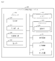
- FIG. 1 is a configuration diagram of a program operating system 200 according to Embodiment 1.
- FIG. 1 is a configuration diagram of a program creation support system 100 according to Embodiment 1.
- FIG. 1 is a functional configuration diagram of a program creation support system 100 according to Embodiment 1.
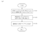
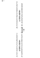
- FIG. 4 is a flowchart of a program creation support method according to Embodiment 1; 4 is a flowchart of step S120 in Embodiment 1; 4 shows an example of a replacement database 191 according to the first embodiment;
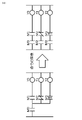
- FIG. FIG. 4 is a diagram showing an example of instruction replacement according to the first embodiment;
- FIG. 4 is a diagram showing an example of instruction replacement according to the first embodiment;
- 4 is a flowchart of step S130 in Embodiment 1;
- FIG. 2 shows an example of a fragmented ladder program according to the first embodiment
- FIG. FIG. 2 shows an example of a fragmented ladder program according to the first embodiment
- FIG. FIG. 11 shows an intermediate representation of the fragmented ladder program (FIG. 11) according to the first embodiment
- FIG. 11 shows an intermediate representation of the fragmented ladder program (FIG. 11) according to the first embodiment
- FIG. 2 shows an example of a fragmented ladder program according to the first embodiment
- FIG. 14 shows an intermediate representation of the fragmented ladder program (FIG. 14) according to the first embodiment
- FIG. FIG. 2 shows an example of a fragmented ladder program according to the first embodiment
- FIG. FIG. 16 shows an intermediate representation of the fragmented ladder program (FIG. 16) according to the first embodiment
- FIG. 16 shows an intermediate representation of the fragmented ladder program (FIG. 16) according to the first embodiment
- FIG. 2 shows an example of a fragmented ladder program according to the first embodiment
- FIG. 18 shows an intermediate representation of the fragmented ladder program (FIG. 18) in Embodiment 1.
- FIG. FIG. 2 shows an example of a fragmented ladder program according to the first embodiment
- FIG. 20 shows an intermediate representation of the fragmented ladder program (FIG. 20) according to the first embodiment
- FIG. FIG. 4 is a diagram showing comparison of character strings between fragments according to the first embodiment
- 4 is a diagram showing an example of a ladder program according to Embodiment 1
- FIG. FIG. 23 is a diagram showing static analysis results for the ladder program (FIG. 23) according to the first embodiment
- FIG. 4 shows a list of type conditions according to the first embodiment
- FIG. 4 shows a list of type conditions according to the first embodiment
- FIG. FIG. 10 is a diagram showing an example of a display screen for functionization candidates according to the first embodiment
- FIG. 10 is a diagram showing an example of a display screen for functionization candidates according to the first embodiment
- FIG. 2 is a hardware configuration diagram of the program creation support system 100 according to Embodiment 1.
- Embodiment 1 The programming support system 100 will be described with reference to FIGS. 1 to 29.
- FIG. 1 A programming support system 100 will be described with reference to FIGS. 1 to 29.
- a program operating system 200 will be described based on FIG.
- a program operating system 200 is an example of a system in which programs are operated.
- a program operation system 200 includes a program creation support system 100 , a control device 210 and a factory line 220 .
- the program creation support system 100 is a system that assists creation of a program to be operated.
- a programmer uses the program creation support system 100 to edit a program.
- the created program is transmitted to control device 210 via network 202 .
- the control device 210 controls the factory line 220 via the network 201 by executing the created program.
- the control device 210 is a factory-oriented device such as a PLC.
- the control device 210 may be a general device such as a personal computer.
- PLC is an abbreviation for Programmable Logic Controller.
- a factory line 220 has one or more facilities 221 controlled by a control device 210 .
- the networks 201 and 202 are, for example, field networks such as CC-Link, general networks such as Ethernet, or dedicated input/output lines.
- the networks 201 and 202 may be the same network or different networks.
- the configuration of the programming support system 100 will be described based on FIG.
- the program creation support system 100 is a computer provided with hardware such as a processor 101 , a memory 102 , a storage 103 , a communication device 104 , an input device 105 and a display device 106 . These pieces of hardware are connected to each other via signal lines.
- the processor 101 is an IC that performs arithmetic processing and controls other hardware.
- processor 101 is a CPU.
- IC is an abbreviation for Integrated Circuit.
- CPU is an abbreviation for Central Processing Unit.
- Memory 102 is a volatile or non-volatile storage device.
- memory 102 is RAM. Data stored in the memory 102 is saved in the storage 103 as needed. RAM is an abbreviation for Random Access Memory.
- the storage 103 is a non-volatile storage device.
- the storage 103 is ROM, HDD, SSD or memory card reader/writer. Data stored in the storage 103 is loaded into the memory 102 as needed.
- ROM is an abbreviation for Read Only Memory.
- HDD is an abbreviation for Hard Disk Drive.
- SSD is an abbreviation for Solid State Drive.
- Communication device 104 is a receiver and transmitter.
- the communication device 104 is a communication board for Ethernet or field network. Communication of the program creation support system 100 is performed using the communication device 104 .
- NIC is an abbreviation for Network Interface Card.
- the input device 105 is a mouse, keyboard, or the like.
- Display device 106 is a display.
- the program creation support system 100 may include a touch panel functioning as the input device 105 and the display device 106 .
- the program creation support system 100 includes elements such as a reception unit 110 , an instruction unification unit 120 , a candidate extraction unit 130 and an output unit 140 . These elements are implemented in software.
- the storage 103 stores a program creation support program for causing the computer to function as the reception unit 110 , the command unification unit 120 , the candidate extraction unit 130 and the output unit 140 .
- the programming support program is loaded into memory 102 and executed by processor 101 .
- the storage 103 also stores an OS. At least part of the OS is loaded into memory 102 and executed by processor 101 .
- the processor 101 executes the programming support program while executing the OS.
- OS is an abbreviation for Operating System.
- Input/output data of the programming support program are stored in the storage unit 190 .
- Storage 103 functions as storage unit 190 .
- a storage device such as the memory 102 , a register within the processor 101 and a cache memory within the processor 101 may function as the storage unit 190 instead of or together with the storage 103 .
- the program creation support system 100 may include multiple processors that substitute for the processor 101 .
- the program creation support program can be recorded (stored) in a computer-readable manner on a non-volatile recording medium such as an optical disc or flash memory.
- the program creation support system 100 includes a reception unit 110 , a command unification unit 120 , a candidate extraction unit 130 and an output unit 140 .
- the instruction unifying section 120 includes an instruction comparing section 121 and a program converting section 122 .
- the candidate extraction unit 130 includes a program fragmentation unit 131, a fragment group extraction unit 132, a dependency analysis unit 133, a fragment group pair extraction unit 134, a fragment group pair comparison unit 135, a function candidate extraction unit 136, and a function candidate extraction unit. 136 and a functionalization candidate aggregating unit 137 .
- the replacement database 191 is stored in the storage unit 190 (see FIG. 2).
- the operation procedure of the program creation support system 100 corresponds to the program creation support method. Further, the procedure of operation of the program creation support system 100 corresponds to the procedure of processing by the program creation support program.
- step S110 the reception unit 110 detects an action by the input device 105 such as a mouse click.
- the receiving unit 110 then reads the target program from the storage unit 190 and passes it to the command unifying unit 120 .
- the target program is a (source) program that is processed by the program creation support system 100 to extract functionalization candidates, and is stored in the storage unit 190 .
- the target program may be one program or may be multiple programs.
- a target program, which is a ladder program, is shown below as an example.
- the target program may be a program written in a programming language such as ST language or SFC language.
- ST is an abbreviation for Structured Text.
- SFC is an abbreviation for Sequential function chart.
- step S120 the instruction unifying unit 120 refers to the replacement database 191 and replaces each instruction to be replaced among the instructions in the target program with a prescribed instruction. Then, the instruction unifying section 120 passes the target program after replacement to the candidate extracting section 130 .
- Substitution database 191 indicates one or more substitution rules.
- a replacement rule includes a replacement condition and a replacement content.
- a replacement condition is a condition of an instruction to be replaced.
- the replacement content is the content of replacing the instruction to be replaced with the default instruction. Depending on the replacement rule, reference to other instructions and editing of other instructions are also required.
- step S120 The procedure of step S120 will be described based on FIG.
- the instruction comparison unit 121 determines whether the instruction is to be replaced according to the replacement condition shown in the replacement database 191 for each instruction in the target program.
- step S122 the program conversion unit 122 replaces each instruction to be replaced with a default instruction according to the replacement rule shown in the replacement database 191.
- step S ⁇ b>123 the program conversion unit 122 passes the target program after replacement to the candidate extraction unit 130 .
- FIG. 6 shows an example of the replacement database 191.
- the replacement database 191 shows multiple replacement rules.
- the replacement condition is "a branch instruction is used” and the replacement content is “describe branch processing separately”.
- the replacement condition is "use an instruction with leading "D”" and the replacement content is "replace with an instruction without "D””.
- FIG. 7 shows an example of replacement based on the first replacement rule.
- FIG. 8 shows an example of replacement based on the second replacement rule.
- step S130 the candidate extraction unit 130 fragments the target program after replacement, and extracts a group of fragments that are candidates for functionalization.
- step S131 the program fragmentation unit 131 fragments the target program into groups of processes.
- the unit of fragmentation may be a line unit or a token unit.
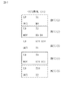
- FIG. 10 shows an example of a ladder program fragmented on a lexical basis.
- LD means ladder diagram.
- IL stands for Instruction List.
- a ladder program one stage corresponds to one token.
- a “stage” means a group from an input to an output in a ladder circuit. In Figure 10, the ladder program is divided into two pieces.
- step S132 the fragment group extraction unit 132 compares the instruction groups of the fragments for each set of fragments in the target program, and determines whether the instruction groups of the fragments match.
- An instruction group is one or more instructions contained in a fragment.
- the fragment group extraction unit 132 extracts pairs of fragments in which the instruction groups of the fragments match among the pairs of fragments in the target program.
- a set to be extracted is called a "fragment group”.
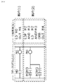
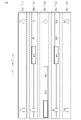
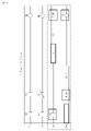
- FIG. 11 shows an example of a fragmented ladder program.
- a number in parentheses at the left end represents the number of steps (the scale of the program).
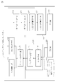
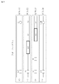
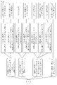
- FIG. 12 shows the intermediate representation (IL) of the ladder program of FIG.
- Arrows connecting fragments represent a comparison of instruction groups between fragments.
- the instruction group of fragment (1) is "LD, OUT”.
- the instruction group of fragment (4) is "LD, OUT”. Therefore, the instruction group of fragment (1) matches the instruction group of fragment (4).
- step S133 the dependency analysis unit 133 analyzes the dependency of variables between fragments for each set of fragments in the target program. A variable dependency exists between fragments if they use the same variable, and one fragment reads the variable and the other fragment writes the variable.
- FIG. 13 shows the intermediate representation (IL) of the ladder program of FIG. Fragment (1) writes variable Y5 and fragment (2) reads variable Y5. Therefore, fragment (1) and fragment (2) have a dependency of variable Y5.
- step S134 the fragment group pair extraction unit 134 compares the instruction groups of the fragment groups for each fragment group pair, and determines whether the instruction groups of the fragment groups match. Then, the fragment group pair extraction unit 134 extracts a pair in which the instruction groups of the fragment groups match among the fragment group pairs. The set to be extracted is called a "fragment group pair".
- the fragment group pair extraction unit 134 determines the types (1) to (3) of the fragment group pairs for each fragment group pair based on the analysis results for each fragment group included in the fragment group pair.
- An analysis result for each fragment group (set of fragments) is obtained in step S133.
- (1) The order of instruction groups is consistent without interchanging fragments. (2) If the fragments are exchanged, the order of the instruction groups will match, and even if the fragments are exchanged, there will be no problem with the dependency of variables between the fragments. (3) If the fragments are exchanged, the order of the instruction groups will match, and if the fragments are exchanged, the dependency of variables between the fragments will be disturbed. However, replacement of fragments is limited to replacement within one program.
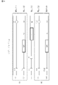
- FIG. 14 shows an example of a fragmented ladder program.
- FIG. 15 shows the intermediate representation (IL) of the ladder program of FIG.
- the instruction group of fragment group (1,2) is "LD, OUT, LD, MOV".
- the instruction group of fragment group (4,5) is "LD, OUT, LD, MOV”. That is, the instruction group of fragment group (1,2) matches the instruction group of fragment group (4,5). Also, the order of the instruction groups of the fragment group (1, 2) is changed to matches the order of Therefore, fragment group (1,2) and fragment group (4,5) are a fragment group pair of type (1).
- FIG. 16 shows an example of a fragmented ladder program.
- FIG. 17 shows the intermediate representation (IL) of the ladder program of FIG.
- the instruction group of fragment group (1,2) is "LD, OUT, LD, MOV".
- the instruction group of fragment group (4,5) is "LD, MOV, LD, OUT". That is, the instruction group of fragment group (1,2) matches the instruction group of fragment group (4,5).
- the order of the instruction group of the fragment group (1, 2) is as follows: if the fragment (1) and the fragment (2) or the fragment (4) and the fragment (5) are exchanged, the instruction group of the fragment group (4, 5) is match the order. Furthermore, there are no variable dependencies between fragment (1) and fragment (2), and no variable dependencies between fragment (4) and fragment (5).
- fragment group (1,2) and fragment group (4,5) are a fragment group pair of type (2).
- FIG. 18 shows an example of a fragmented ladder program.
- FIG. 19 shows the intermediate representation (IL) of the ladder program of FIG.
- the instruction group of fragment group (1,2) is "LD, OUT, LD, MOV".
- the instruction group of fragment group (4,5) is "LD, MOV, LD, OUT". That is, the instruction group of fragment group (1,2) matches the instruction group of fragment group (4,5). Also, the order of the instruction groups of the fragment group (1,2) matches the order of the instruction groups of the fragment group (4,5) by interchanging the fragment (1) and the fragment (2). Further, fragment (1) and fragment (2) have no variable dependency, but fragment (4) and fragment (5) have variable M10 dependency. Therefore, if the fragment (4) and the fragment (5) are exchanged, the dependency of the variable M10 will be disturbed. Therefore, fragment group (1,2) and fragment group (4,5) are a fragment group pair of type (3).
- step S135 the fragment group pair comparison unit 135 compares how the variable groups of the fragment groups are used for each fragment group pair, and determines whether the usage of the variable groups of the fragment groups matches. If the usage of variable groups, such as the number of times each variable is used and the order of instructions for each variable, does not match between the fragment groups, the fragment group pairs cannot be functionalized (commonized). Therefore, step S135 is executed. However, since an input variable and an output variable can be set individually for a function, it is not necessary for each fragment group to have the same variable name in the variable group.
- the fragment group pair comparison unit 135 operates as follows. First, for each fragment group, the fragment group pair comparison unit 135 sequentially arranges each instruction and each variable name in the fragment group to generate a character string. Next, the fragment group pair comparison unit 135 replaces each variable name in the character string with a specified variable name in order for each fragment group. However, the same variable name in the string is replaced with the same default variable name. For example, the fragment group pair comparison unit 135 replaces each variable name with "dx". "x" is an index that increases by 1 from 0. Next, the fragment group pair comparison unit 135 compares the character strings of the fragment groups. Then, when the character strings of the fragment groups match, the fragment group pair comparison unit 135 determines that the usage of the variable groups of the fragment groups match.
- FIG. 20 shows an example of a ladder program.
- FIG. 21 shows the intermediate representation (IL) of the ladder program of FIG. Fragment (1) and fragment (2) are referred to as fragment group (A). Fragment (4) and fragment (5) are referred to as fragment group (B). Fragment group (A) and fragment group (B) are a fragment group pair.
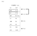
- FIG. 22 shows character strings obtained from fragment group (A) and character strings obtained from fragment group (B). Character string (A) is obtained by extracting each variable and each variable in order from fragment group (A).
- a character string (A') is obtained by replacing each variable name in the character string (A) with a predetermined variable name in order.
- a character string (B) is obtained by extracting each variable and each variable in order from the fragment group (B).
- a character string (B') is obtained by replacing each variable name in the character string (B) with a predetermined variable name in order.
- String (A') matches string (B'). Therefore, fragment group (A) and fragment group (B)
- step S ⁇ b>136 the function candidate extraction unit 136 determines whether the variable types of the fragment groups match for each fragment group pair in which the usage of the variable groups of the fragment groups match.
- the types of variables are input variables, output variables, input/output variables, internal variables, and the like.
- a static analysis tool is used in combination with a list of type conditions.
- the type condition list shows variable conditions for each variable type.
- the function candidate extraction unit 136 extracts fragment group pairs in which the usage of variable groups between fragment groups and the type of each variable between fragment groups match.
- the extracted fragment group pair is called a "function candidate".
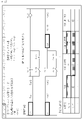
- FIG. 23 shows an example of a ladder program.
- FIG. 24 shows an example of analysis results obtained by using a static analysis tool on the ladder program of FIG.
- the program name is ProgPou.
- the number of starting steps is 6 steps.
- the number of ending steps is 14 steps.
- the objects of static analysis are fragment (6) and fragment (10).
- the starting point of static analysis is "Y0".
- the type condition list indicates conditions for each of types (1) to (10).
- *1 to *4 in FIG. 26 mean the following.
- *1 Only when the value of the target variable does not need to be held due to the processing content of the program, the type of the target variable can be set as an output variable.
- *2 Only when the number of steps of variables connected to the left side is smaller than the number of steps on the right side, and it is not necessary to hold the target variable value due to the processing content of the program, the type of the target variable can be set as an output variable.
- *3 Only when the number of steps of the variables connected to the left side is smaller than that of the right side, the type of the target variable can be set as an input variable.
- *4 Only when the number of steps for variables connected to the left side is smaller than the number of steps on the right side, and the value of the target variable does not need to be retained due to the processing content of the program, the type of the target variable can be set to an internal variable. is.
- step S137 the functional candidate aggregation unit 137 compares the types of variables of the functional candidates and determines whether the variable types of the functional candidates match. Then, the functionalization candidate aggregating unit 137 aggregates functionalization candidates having the same variable type.
- step S140 the output unit 140 outputs information on candidates for functionalization. Specifically, the output unit 140 displays information on the display device 106 for each group of functionization candidates.
- the display is an example of output.
- the output information includes the information obtained in each step of step S130. For example, the output information includes the types of fragment group pairs included in the collection of functionization candidates.
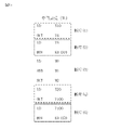
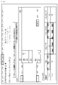
- FIG. 27 and 28 show examples of display screens of candidates for functionization.
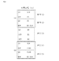
- FIG. 27 shows pattern 1 of a collection of functionization candidates. In [Variable Allocation], hatching indicates types of variables that cannot be used.
- FIG. 28 shows pattern 3 of the collection of functionization candidates. Moreover, it is shown that pattern 3 cannot be functionalized if pattern 1 is functionalized.
- the programming support system 100 has functions (1) to (3).
- This function is implemented by the instruction unifying section 120 .
- This function is implemented by the candidate extraction unit 130 .
- This function is implemented by the candidate extraction unit 130 and the output unit 140.
- Embodiment 1 *** Effect of Embodiment 1 *** According to Embodiment 1, it is possible to present candidates for functionalization in the target program. Depending on the programmer, the writing style (instructions used) and writing order may differ even for the same process. Embodiment 1 can extract functionization candidates regardless of the instructions used and the description order. The first embodiment can be expected to reduce engineering man-hours required for users to extract common processes.
- the programming support system 100 has a processing circuit 109 .
- the processing circuit 109 is hardware that implements the reception unit 110 , the command unification unit 120 , the candidate extraction unit 130 and the output unit 140 .
- the processing circuit 109 may be dedicated hardware, or may be the processor 101 that executes a program stored in the memory 102 .
- processing circuitry 109 may be, for example, a single circuit, multiple circuits, a programmed processor, a parallel programmed processor, an ASIC, an FPGA, or a combination thereof.
- ASIC is an abbreviation for Application Specific Integrated Circuit.
- FPGA is an abbreviation for Field Programmable Gate Array.
- the program creation support system 100 may include a plurality of processing circuits that substitute for the processing circuit 109.
- processing circuit 109 some functions may be implemented by dedicated hardware, and the remaining functions may be implemented by software or firmware.
- the functions of the programming support system 100 can be realized by hardware, software, firmware, or a combination thereof.
- Program creation support system 100 may be realized by a plurality of devices.
- the "unit”, which is an element of the program creation support system 100, may be read as "processing”, “process”, “circuit” or “circuitry”.
- program creation support system 101 processor, 102 memory, 103 storage, 104 communication device, 105 input device, 106 display device, 109 processing circuit, 110 reception unit, 120 command unification unit, 121 command comparison unit, 122 program conversion unit, 130
- Candidate extraction unit 131
- Program fragmentation unit 132
- Fragment group extraction unit 133
- Dependency analysis unit 134
- Fragment group pair extraction unit 135
- Fragment group pair comparison unit 136
- Function candidate extraction unit 137
- Function candidate aggregation unit 140 output section, 190 storage section, 191 replacement database, 200 program operation system, 201 network, 202 network, 210 control device, 220 factory line, 221 facility.
Landscapes
- Engineering & Computer Science (AREA)
- Physics & Mathematics (AREA)
- General Physics & Mathematics (AREA)
- Automation & Control Theory (AREA)
- Software Systems (AREA)
- General Engineering & Computer Science (AREA)
- Theoretical Computer Science (AREA)
- Stored Programmes (AREA)
- Devices For Executing Special Programs (AREA)
- Programmable Controllers (AREA)
- Debugging And Monitoring (AREA)
Abstract
Description
しかし、プログラム内にある類似処理を人手で抽出するには限界がある。そのため、プログラム内にある類似処理を自動で抽出してユーザに提示する技術が求められている。
特許文献1は、共通処理を自動抽出する技術を開示している。その技術では、2つのラダー回路のうちの少なくとも一つのラダー回路に対して、論理式の結果が変わらないように変数の順序が並び替えられる。そして、ラダー回路同士の論理式が比較され、論理式が一致するか否かが判定される。
対象プログラムを処理のまとまりごとに断片化するプログラム断片化部と、
断片の組のうち断片同士の命令群が一致する組を断片群として抽出する断片群抽出部と、
断片群の組のうち断片群同士の命令群と断片群同士の変数群の使われ方と断片群同士の各変数の種別が一致する組を関数化候補として抽出する関数化候補抽出部と、
関数化候補の情報を出力する出力部と、を備える。
プログラム作成支援システム100について、図1から図29に基づいて説明する。
プログラム運用システム200は、プログラムが運用されるシステムの例である。
プログラム運用システム200は、プログラム作成支援システム100と、制御機器210と、工場ライン220と、を備える。
作成されたプログラムは、ネットワーク202を介して、制御機器210に伝達される。
具体的には、制御機器210は、PLCなどの工場向けの機器である。但し、制御機器210は、パーソナルコンピュータのような一般的な機器であってもよい。
PLCは、Programmable Logic Controllerの略称である。
ネットワーク201とネットワーク202は、同じネットワークであってもよいし、互いに異なるネットワークであってもよい。
プログラム作成支援システム100は、プロセッサ101とメモリ102とストレージ103と通信装置104と入力装置105と表示装置106といったハードウェアを備えるコンピュータである。これらのハードウェアは、信号線を介して互いに接続されている。
ICは、Integrated Circuitの略称である。
CPUは、Central Processing Unitの略称である。
RAMは、Random Access Memoryの略称である。
ROMは、Read Only Memoryの略称である。
HDDは、Hard Disk Driveの略称である。
SSDは、Solid State Driveの略称である。
NICは、Network Interface Cardの略称である。
表示装置106は、ディスプレイである。
プログラム作成支援システム100は、入力装置105と表示装置106として機能するタッチパネルを備えてもよい。
ストレージ103には、さらに、OSが記憶されている。OSの少なくとも一部は、メモリ102にロードされて、プロセッサ101によって実行される。
プロセッサ101は、OSを実行しながら、プログラム作成支援プログラムを実行する。
OSは、Operating Systemの略称である。
ストレージ103は記憶部190として機能する。但し、メモリ102、プロセッサ101内のレジスタおよびプロセッサ101内のキャッシュメモリなどの記憶装置が、ストレージ103の代わりに、又は、ストレージ103と共に、記憶部190として機能してもよい。
プログラム作成支援システム100は、受付部110と命令統一部120と候補抽出部130と出力部140とを備える。
命令統一部120は、命令比較部121とプログラム変換部122とを備える。
候補抽出部130は、プログラム断片化部131と断片群抽出部132と依存関係解析部133と断片群ペア抽出部134と断片群ペア比較部135と関数化候補抽出部136と関数化候補抽出部136と関数化候補集約部137とを備える。
置換データベース191は、記憶部190(図2を参照)に記憶される。
プログラム作成支援システム100の動作の手順はプログラム作成支援方法に相当する。また、プログラム作成支援システム100の動作の手順はプログラム作成支援プログラムによる処理の手順に相当する。
ステップS110において、受付部110は、マウスのクリックなど入力装置105によるアクションを検知する。
そして、受付部110は、対象プログラムを記憶部190から読み出して命令統一部120に渡す。
対象プログラムは、プログラム作成支援システム100によって処理されて関数化候補が抽出される(ソース)プログラムであり、記憶部190に記憶される。対象プログラムは、1つのプログラムであってもよいし、複数のプログラムであってもよい。
以下、ラダープログラムである対象プログラムを例に示す。但し、対象プログラムは、ST言語またはSFC言語などのプログラミング言語で記述されたプログラムであってもよい。
STは、Structured Textの略称である。
SFCは、Sequential function chartの略称である。
そして、命令統一部120は、置換後の対象プログラムを候補抽出部130に渡す。
置換データベース191は、1つ以上の置換規則を示す。
置換規則は、置換条件と置換内容とを含む。
置換条件は、置換対象となる命令の条件である。
置換内容は、置換対象となる命令を既定の命令に置き換える内容である。
なお、置換規則によっては、他の命令の参照および他の命令の編集も必要となる。
ステップS121において、命令比較部121は、対象プログラムの中の命令ごとに、置換データベース191に示される置換条件にしたがって、命令が置換対象であるか判定する。
図6において、置換データベース191は、複数の置換規則を示している。
第1置換規則において、置換条件は「分岐命令が使用される」であり、置換内容は「分岐処理を分けて記述する」である。
第2置換規則において、置換条件は「先頭に「D」が付く命令が使用される」であり、置換内容は「「D」が付かない命令に置き換える」である。
図7に、第1置換規則に基づく置換の例を示す。
図8に、第2置換規則に基づく置換の例を示す。
ステップS130において、候補抽出部130は、置換後の対象プログラムを断片化し、関数化候補となる断片群を抽出する。
ステップS131において、プログラム断片化部131は、対象プログラムを処理のまとまりごとに断片化する。
断片化の単位は、行単位であってもよいし、字句単位であってもよい。
ラダープログラムでは、1つの段が1つの字句に相当する。「段」は、ラダー回路における入力から出力までのひとまとまりを意味する。
図10において、ラダープログラムは、2つの断片に分けられている。
ステップS132において、断片群抽出部132は、対象プログラムの中の断片の組ごとに、断片同士の命令群を比較し、断片同士の命令群が一致するか判定する。
命令群は、断片に含まれる1つ以上の命令である。
図12に、図11のラダープログラムの中間表現(IL)を示す。断片同士を繋ぐ矢印は、断片同士の命令群の比較を表す。
断片(1)の命令群は「LD、OUT」である。また、断片(4)の命令群は「LD、OUT」である。
したがって、断片(1)の命令群は断片(4)の命令群と一致する。
ステップS133において、依存関係解析部133は、対象プログラムの中の断片の組ごとに、断片間の変数の依存関係を解析する。
断片同士が同じ変数を使用し、一方の断片がその変数を読み込み、他方の断片がその変数を書き込む場合、断片間に変数の依存関係がある。
断片(1)は変数Y5を書き込み、断片(2)は変数Y5を読み込む。
したがって、断片(1)と断片(2)は、変数Y5の依存関係を有する。
ステップS134において、断片群ペア抽出部134は、断片群の組ごとに、断片群同士の命令群を比較し、断片群同士の命令群が一致するか判定する。
そして、断片群ペア抽出部134は、断片群の組のうち断片群同士の命令群が一致する組を抽出する。抽出される組を「断片群ペア」と称する。
(1)断片を入れ替えずに命令群の順序が一致する。
(2)断片を入れ替えると命令群の順序が一致し、断片を入れ替えても断片間の変数の依存関係に支障がでない。
(3)断片を入れ替えると命令群の順序が一致し、断片を入れ替えると断片間の変数の依存関係に支障がでる。
ただし、断片の入れ替えは、1つのプログラムの中での入れ替えに限定される。
図15に、図14のラダープログラムの中間表現(IL)を示す。
断片群(1、2)の命令群は「LD、OUT、LD、MOV」である。断片群(4、5)の命令群は「LD、OUT、LD、MOV」である。つまり、断片群(1、2)の命令群は断片群(4、5)の命令群と一致する。
また、断片群(1、2)の命令群の順序は、断片(1)と断片(2)または断片(4)と断片(5)を入れ替えずに、断片群(4、5)の命令群の順序と一致する。
したがって、断片群(1、2)と断片群(4、5)は、種類(1)の断片群ペアである。
図17に、図16のラダープログラムの中間表現(IL)を示す。
断片群(1、2)の命令群は「LD、OUT、LD、MOV」である。断片群(4、5)の命令群は「LD、MOV、LD、OUT」である。つまり、断片群(1、2)の命令群は断片群(4、5)の命令群と一致する。
また、断片群(1、2)の命令群の順序は、断片(1)と断片(2)または断片(4)と断片(5)を入れ替えると、断片群(4、5)の命令群の順序と一致する。
さらに、断片(1)と断片(2)に変数の依存関係はなく、断片(4)と断片(5)にも変数の依存関係はない。そのため、断片(1)と断片(2)を入れ替えても、断片(4)と断片(5)を入れ替えても、断片間の変数の依存関係に支障がでない。
したがって、断片群(1、2)と断片群(4、5)は、種類(2)の断片群ペアである。
図19に、図18のラダープログラムの中間表現(IL)を示す。
断片群(1、2)の命令群は「LD、OUT、LD、MOV」である。断片群(4、5)の命令群は「LD、MOV、LD、OUT」である。つまり、断片群(1、2)の命令群は断片群(4、5)の命令群と一致する。
また、断片群(1、2)の命令群の順序は、断片(1)と断片(2)を入れ替えると、断片群(4、5)の命令群の順序と一致する。
さらに、断片(1)と断片(2)に変数の依存関係はないが、断片(4)と断片(5)には変数M10の依存関係がある。そのため、断片(4)と断片(5)を入れ替えると変数M10の依存関係に支障がでる。
したがって、断片群(1、2)と断片群(4、5)は、種類(3)の断片群ペアである。
ステップS135において、断片群ペア比較部135は、断片群ペアごとに、断片群同士の変数群の使われ方を比較し、断片群同士の変数群の使われ方が一致するか判定する。
各変数が使用される回数および各変数に対する命令の順番などの変数群の使われ方が断片群間で一致しない場合、断片群ペアを関数化(共通化)することができない。そのため、ステップS135が実行される。
但し、関数には入力変数および出力変数を個別に設定できるため、断片群同士で変数群の各変数名が一致する必要はない。
まず、断片群ペア比較部135は、断片群ごとに、断片群の中の各命令と各変数名を順番に並べて文字列を生成する。
次に、断片群ペア比較部135は、断片群ごとに、文字列の中の各変数名を順番に応じた規定の変数名に置き換える。但し、文字列の中の同じ変数名は同じ既定の変数名に置き換えられる。例えば、断片群ペア比較部135は、各変数名を「dx」に置き換える。「x」は0から1ずつ増えるインデックスである。
次に、断片群ペア比較部135は、断片群同士の文字列を比較する。
そして、断片群同士の文字列が一致する場合、断片群ペア比較部135は、断片群同士の変数群の使われ方が一致すると判定する。
図21に、図20のラダープログラムの中間表現(IL)を示す。
断片(1)と断片(2)を断片群(A)と称する。断片(4)と断片(5)を断片群(B)と称する。断片群(A)と断片群(B)は断片群ペアである。
図22に、断片群(A)から得られる文字列と断片群(B)から得られる文字列を示す。
断片群(A)から各変数と各変数を順番に抽出すると文字列(A)が得られる。
文字列(A)の中の各変数名を順番に応じて既定の変数名に置き換えると文字列(A’)が得られる。
断片群(B)から各変数と各変数を順番に抽出すると文字列(B)が得られる。
文字列(B)の中の各変数名を順番に応じて既定の変数名に置き換えると文字列(B’)が得られる。
文字列(A’)は文字列(B’)と一致する。
したがって、断片群(A)と断片群(B)は、変数群の使われ方が一致する。
ステップS136において、関数化候補抽出部136は、断片群同士の変数群の使われ方が一致する断片群ペアごとに、断片群同士の各変数の種別が一致するか判定する。
例えば、変数の種別は、入力変数、出力変数、入出力変数または内部変数などである。
図24に、図23のラダープログラムに対して静的解析ツールを使用することによって得られる解析結果の例を示す。
図23および図24において、破線で囲われた範囲が関数化対象の範囲である。
プログラム名はProgPouである。
開始ステップ数は6stepである。
終了ステップ数は14stepである。
静的解析の対象は、断片(6)と断片(10)である。
静的解析の起点は、「Y0」である。
種別条件一覧は、種別(1)から種別(10)のそれぞれの条件を示している。
図26の※1から※4は以下を意味する。
※1:プログラムの処理内容的に対象変数の値を保持する必要がない場合に限り、対象変数の種別を出力変数とすることが可能である。
※2:右側より左側に繋がる変数のステップ数の方が全て小さく、プログラムの処理内容的に対象変数値を保持する必要がない場合に限り、対象変数の種別を出力変数とすることが可能である。
※3:右側より左側に繋がる変数のステップ数の方が全て小さい場合に限り、対象変数の種別を入力変数にすることが可能である。
※4:右側より左側に繋がる変数のステップ数の方が全て小さく、プログラムの処理内容的に対象変数の値を保持する必要がない場合に限り、対象変数の種別を内部変数にすることが可能である。
図24の「M0」において、入力「X0」は関数化対象外であり、「M0」の出力「D100」は関数化対象内である。図26の(5)に対応する入力変数が候補となる。
図24の「D100」において、入力「M0」は関数化対象内であり、出力「Y0」は関数化対象内である。図26の(10)に対応する内部変数が候補となる。
図24の「Y0」において、入力「D100」は関数化対象内である。出力はない。図25の(2)に対応する出力変数が候補となる。
ステップS137において、関数化候補集約部137は、関数化候補同士の各変数の種別を比較し、関数化候補同士の各変数の種別が一致するか判定する。
そして、関数化候補集約部137は、各変数の種別が一致する関数化候補同士を集約する。
ステップS140において、出力部140は、関数化候補の情報を出力する。
具体的には、出力部140は、関数化候補の集まりごとに情報を表示装置106に表示する。表示は出力の一例である。
出力される情報には、ステップS130の各ステップで得られた情報が含まれる。例えば、出力される情報には、関数化候補の集まりに含まれる断片群ペアの種類が含まれる。
図27は、関数化候補の集まりのパターン1を示している。[変数割付]において、網掛けは使用できない変数の種別を示している。
図28は、関数化候補の集まりのパターン3を示している。また、パターン1を関数化するとパターン3を関数化することができないことが示されている。
プログラム作成支援システム100は、機能(1)~機能(3)を有する。
(1)対象プログラムにおいて異なる命令で書かれた同じ処理を同じ命令に統一する。この機能は命令統一部120によって実現される。
(2)順番を入れ替えることで同じ構成となる関数化候補を見つける。この機能は候補抽出部130によって実現される。
(3)プログラム(断片)の実行順序を変更しないもの、プログラムの実行順序を変更することでプログラム間の依存関係に影響を及びさないもの、プログラムの実行順序を変更することでプログラム間の依存関係に影響を及ぼすもの、に分けて関数化候補を表示する。この機能は、候補抽出部130と出力部140によって実現される。
実施の形態1により、対象プログラムの中の関数化候補を提示することができる。
プログラマーによって、同じ処理でも書き方(使用する命令)および記述順序が異なる場合がある。実施の形態1は、使用命令および記述順序に関わらず関数化候補を抽出することができる。
実施の形態1によって、利用者による共通処理の抽出に要するエンジニアリング工数の削減が期待できる。
図29に基づいて、プログラム作成支援システム100のハードウェア構成を説明する。
プログラム作成支援システム100は処理回路109を備える。
処理回路109は、受付部110と命令統一部120と候補抽出部130と出力部140とを実現するハードウェアである。
処理回路109は、専用のハードウェアであってもよいし、メモリ102に格納されるプログラムを実行するプロセッサ101であってもよい。
ASICは、Application Specific Integrated Circuitの略称である。
FPGAは、Field Programmable Gate Arrayの略称である。
プログラム作成支援システム100の要素である「部」は、「処理」、「工程」、「回路」または「サーキットリ」と読み替えてもよい。
Claims (7)
- 対象プログラムを処理のまとまりごとに断片化するプログラム断片化部と、
断片の組のうち断片同士の命令群が一致する組を断片群として抽出する断片群抽出部と、
断片群の組のうち断片群同士の命令群と断片群同士の変数群の使われ方と断片群同士の各変数の種別が一致する組を関数化候補として抽出する関数化候補抽出部と、
関数化候補の情報を出力する出力部と、
を備えるプログラム作成支援システム。 - 前記プログラム作成支援システムは、
断片群の組のうち断片群同士の命令群が一致する組を断片群ペアとして抽出する断片群ペア抽出部と、
断片群ペアごとに断片群同士の変数群の使われ方が一致するか判定する断片群ペア比較部と、を備え、
前記断片群ペア比較部は、断片群ペアに含まれる断片群ごとに断片群の中の各命令と各変数名を順番に並べて文字列を生成し、断片群ペアに含まれる断片群ごとに文字列の中の各変数名を順番に応じて規定の変数名に置き換え、断片群同士の文字列を比較し、断片群同士の文字列が一致する場合に断片群同士の変数群の使われ方が一致すると判定する
請求項1に記載のプログラム作成支援システム。 - 前記プログラム作成支援システムは、
関数化候補同士の各変数の種別を比較し、各変数の種別が一致する関数化候補同士を集約する関数化候補集約部を備え、
前記出力部は、各変数の種別が一致する関数化候補の集まりごとに関数化候補の集まりの情報を出力する
請求項1または請求項2に記載のプログラム作成支援システム。 - 前記プログラム作成支援システムは、
断片群ごとに断片間の変数の依存関係を解析する依存関係解析部と、
断片群の組のうち断片群同士の命令群が一致する組を断片群ペアとして抽出し、断片群ペアごとに断片群ペアに含まれる各断片群に対する解析結果に基づいて断片群ペアの種類を判定する断片群ペア抽出部と、を備え、
前記出力部は、前記関数化候補となる断片群ペアの種類を含んだ前記情報を出力する
請求項1から請求項3のいずれか1項に記載のプログラム作成支援システム。 - 前記断片群ペア抽出部は、断片群ペアごとに、断片群ペアの種類が、断片を入れ替えずに命令群の順序が一致するという種類と、断片を入れ替えると命令群の順序が一致し、断片を入れ替えても断片間の変数の依存関係に支障がでないという種類と、断片を入れ替えると命令群の順序が一致し、断片を入れ替えると断片間の変数の依存関係に支障がでるという種類のいずれであるか判定する
請求項4に記載のプログラム作成支援システム。 - 前記プログラム作成支援システムは、
1つ以上の置換規則を示す置換データベースを参照し、前記対象プログラムの中の命令のうち置換対象である各命令を規定の命令に置換する命令統一部を備え、
前記プログラム断片化部は、置換後の前記対象プログラムを断片化する
請求項1から請求項5のいずれか1項に記載のプログラム作成支援システム。 - 対象プログラムを処理のまとまりごとに断片化するプログラム断片化処理と、
断片の組のうち断片同士の命令群が一致する組を断片群として抽出する断片群抽出処理と、
断片群の組のうち断片群同士の命令群と断片群同士の変数群の使われ方と断片群同士の各変数の種別が一致する組を関数化候補として抽出する関数化候補抽出処理と、
関数化候補の情報を出力する出力処理と、
をコンピュータに実行させるためのプログラム作成支援プログラム。
Priority Applications (5)
| Application Number | Priority Date | Filing Date | Title |
|---|---|---|---|
| JP2023508381A JP7378666B2 (ja) | 2021-03-26 | 2021-03-26 | プログラム作成支援システムおよびプログラム作成支援プログラム |
| PCT/JP2021/012914 WO2022201506A1 (ja) | 2021-03-26 | 2021-03-26 | プログラム作成支援システムおよびプログラム作成支援プログラム |
| CN202180096142.0A CN117043745A (zh) | 2021-03-26 | 2021-03-26 | 程序创建辅助系统以及程序创建辅助程序 |
| TW110131412A TW202238289A (zh) | 2021-03-26 | 2021-08-25 | 程式製成支援系統及程式製成支援程式產品 |
| US18/230,372 US20230375999A1 (en) | 2021-03-26 | 2023-08-04 | Program creation assistance system and computer readable medium |
Applications Claiming Priority (1)
| Application Number | Priority Date | Filing Date | Title |
|---|---|---|---|
| PCT/JP2021/012914 WO2022201506A1 (ja) | 2021-03-26 | 2021-03-26 | プログラム作成支援システムおよびプログラム作成支援プログラム |
Related Child Applications (1)
| Application Number | Title | Priority Date | Filing Date |
|---|---|---|---|
| US18/230,372 Continuation US20230375999A1 (en) | 2021-03-26 | 2023-08-04 | Program creation assistance system and computer readable medium |
Publications (1)
| Publication Number | Publication Date |
|---|---|
| WO2022201506A1 true WO2022201506A1 (ja) | 2022-09-29 |
Family
ID=83396525
Family Applications (1)
| Application Number | Title | Priority Date | Filing Date |
|---|---|---|---|
| PCT/JP2021/012914 Ceased WO2022201506A1 (ja) | 2021-03-26 | 2021-03-26 | プログラム作成支援システムおよびプログラム作成支援プログラム |
Country Status (5)
| Country | Link |
|---|---|
| US (1) | US20230375999A1 (ja) |
| JP (1) | JP7378666B2 (ja) |
| CN (1) | CN117043745A (ja) |
| TW (1) | TW202238289A (ja) |
| WO (1) | WO2022201506A1 (ja) |
Citations (2)
| Publication number | Priority date | Publication date | Assignee | Title |
|---|---|---|---|---|
| JPH08328904A (ja) * | 1995-03-31 | 1996-12-13 | Hitachi Software Eng Co Ltd | プログラム開発支援装置 |
| JP2016177454A (ja) * | 2015-03-19 | 2016-10-06 | 富士通株式会社 | 動作合成方法、動作合成プログラムおよび動作合成装置 |
Family Cites Families (7)
| Publication number | Priority date | Publication date | Assignee | Title |
|---|---|---|---|---|
| JPH09198110A (ja) * | 1996-01-18 | 1997-07-31 | Nissan Motor Co Ltd | ラダーシーケンス回路の最適化方法 |
| US20050033457A1 (en) * | 2003-07-25 | 2005-02-10 | Hitoshi Yamane | Simulation aid tools and ladder program verification systems |
| DE112013006769T5 (de) * | 2013-03-29 | 2015-11-26 | Mitsubishi Electric Corp. | Erzeugungsprogramm für Ablaufprogramm-Komponenten und Vorrichtung zur Erzeugung von Ablaufprogramm-Komponenten |
| CN105144004B (zh) * | 2013-04-08 | 2017-11-10 | 三菱电机株式会社 | 程序图显示装置以及程序图显示方法 |
| JP2019095896A (ja) * | 2017-11-20 | 2019-06-20 | ファナック株式会社 | プログラム比較装置およびプログラム比較方法 |
| JP7423895B2 (ja) * | 2019-03-12 | 2024-01-30 | オムロン株式会社 | ラダー図プログラム作成支援装置、ラダー図プログラム作成支援方法、およびラダー図プログラム作成支援プログラム |
| WO2020213059A1 (ja) * | 2019-04-16 | 2020-10-22 | 三菱電機株式会社 | プログラム作成支援装置、プログラム作成支援方法およびプログラム |
-
2021
- 2021-03-26 CN CN202180096142.0A patent/CN117043745A/zh active Pending
- 2021-03-26 JP JP2023508381A patent/JP7378666B2/ja active Active
- 2021-03-26 WO PCT/JP2021/012914 patent/WO2022201506A1/ja not_active Ceased
- 2021-08-25 TW TW110131412A patent/TW202238289A/zh unknown
-
2023
- 2023-08-04 US US18/230,372 patent/US20230375999A1/en active Pending
Patent Citations (2)
| Publication number | Priority date | Publication date | Assignee | Title |
|---|---|---|---|---|
| JPH08328904A (ja) * | 1995-03-31 | 1996-12-13 | Hitachi Software Eng Co Ltd | プログラム開発支援装置 |
| JP2016177454A (ja) * | 2015-03-19 | 2016-10-06 | 富士通株式会社 | 動作合成方法、動作合成プログラムおよび動作合成装置 |
Also Published As
| Publication number | Publication date |
|---|---|
| CN117043745A (zh) | 2023-11-10 |
| JPWO2022201506A1 (ja) | 2022-09-29 |
| US20230375999A1 (en) | 2023-11-23 |
| TW202238289A (zh) | 2022-10-01 |
| JP7378666B2 (ja) | 2023-11-13 |
Similar Documents
| Publication | Publication Date | Title |
|---|---|---|
| US7676492B2 (en) | Migration of database using serialized objects | |
| KR101401158B1 (ko) | 프로젝트 데이터 작성 장치 및 프로그래머블 표시기 | |
| US12124844B2 (en) | Methods and arrangements to process comments | |
| CN112463586B (zh) | 一种自动化生成应用程序接口测试用例的方法及介质 | |
| US10678864B2 (en) | Analysis model preparing system, programming apparatus, and analysis model preparing method | |
| US8701084B1 (en) | Preview of auto-fix changes to software code | |
| WO2018154657A1 (ja) | 等価性検証装置および等価性検証プログラム | |
| WO2022201506A1 (ja) | プログラム作成支援システムおよびプログラム作成支援プログラム | |
| CN1938683A (zh) | 数据处理设备中避免应用程序的不同功能对全局变量的访问之间的数据不一致性的方法 | |
| WO2020174581A1 (ja) | 情報処理装置、情報処理方法及び情報処理プログラム | |
| US9659142B1 (en) | Methods, systems, and articles of manufacture for trace warping for electronic designs | |
| CN115794048A (zh) | 用于生成源代码的方法和计算机系统 | |
| CN114780154A (zh) | 一种兼容不同生产厂家主控板硬件状态的方法 | |
| KR102601979B1 (ko) | 소프트웨어 프로그램을 검증하는 방법 및 장치 | |
| JP7008780B2 (ja) | 状態遷移編集装置および状態遷移編集プログラム | |
| JP7524978B2 (ja) | プログラム解析支援装置、プログラム解析支援方法、及びプログラム | |
| WO2015181876A1 (ja) | システム運用支援方法および計算機 | |
| WO2025099881A1 (ja) | 修正装置、修正方法、及び修正プログラム | |
| US20080155504A1 (en) | Method and system for automated merging of multiple versions of a software component for an application | |
| JP2014203343A (ja) | プログラム解析装置及びプログラム解析方法 | |
| JP5935319B2 (ja) | 回路エミュレーション装置、回路エミュレーション方法及び回路エミュレーションプログラム | |
| JP7447574B2 (ja) | サポート装置、サポートプログラムおよびサポート方法 | |
| CN118113263A (zh) | 增量构建方法、装置、电子设备及存储介质 | |
| JP2024090191A (ja) | リファクタリング効果評価装置、リファクタリング効果評価方法、及びプログラム | |
| JP2025086679A (ja) | 情報処理装置 |
Legal Events
| Date | Code | Title | Description |
|---|---|---|---|
| 121 | Ep: the epo has been informed by wipo that ep was designated in this application |
Ref document number: 21933111 Country of ref document: EP Kind code of ref document: A1 |
|
| ENP | Entry into the national phase |
Ref document number: 2023508381 Country of ref document: JP Kind code of ref document: A |
|
| WWE | Wipo information: entry into national phase |
Ref document number: 202180096142.0 Country of ref document: CN |
|
| NENP | Non-entry into the national phase |
Ref country code: DE |
|
| 122 | Ep: pct application non-entry in european phase |
Ref document number: 21933111 Country of ref document: EP Kind code of ref document: A1 |