WO2022201496A1 - バイタル検出装置、バイタル検出方法及び車載装置 - Google Patents
バイタル検出装置、バイタル検出方法及び車載装置 Download PDFInfo
- Publication number
- WO2022201496A1 WO2022201496A1 PCT/JP2021/012896 JP2021012896W WO2022201496A1 WO 2022201496 A1 WO2022201496 A1 WO 2022201496A1 JP 2021012896 W JP2021012896 W JP 2021012896W WO 2022201496 A1 WO2022201496 A1 WO 2022201496A1
- Authority
- WO
- WIPO (PCT)
- Prior art keywords
- noise
- unit
- frequency
- sensor signal
- band
- Prior art date
- Legal status (The legal status is an assumption and is not a legal conclusion. Google has not performed a legal analysis and makes no representation as to the accuracy of the status listed.)
- Ceased
Links
Images






Classifications
-
- A—HUMAN NECESSITIES
- A61—MEDICAL OR VETERINARY SCIENCE; HYGIENE
- A61B—DIAGNOSIS; SURGERY; IDENTIFICATION
- A61B5/00—Measuring for diagnostic purposes; Identification of persons
- A61B5/68—Arrangements of detecting, measuring or recording means, e.g. sensors, in relation to patient
- A61B5/6887—Arrangements of detecting, measuring or recording means, e.g. sensors, in relation to patient mounted on external non-worn devices, e.g. non-medical devices
- A61B5/6893—Cars
-
- A—HUMAN NECESSITIES
- A61—MEDICAL OR VETERINARY SCIENCE; HYGIENE
- A61B—DIAGNOSIS; SURGERY; IDENTIFICATION
- A61B5/00—Measuring for diagnostic purposes; Identification of persons
- A61B5/72—Signal processing specially adapted for physiological signals or for diagnostic purposes
- A61B5/7203—Signal processing specially adapted for physiological signals or for diagnostic purposes for noise prevention, reduction or removal
-
- A—HUMAN NECESSITIES
- A61—MEDICAL OR VETERINARY SCIENCE; HYGIENE
- A61B—DIAGNOSIS; SURGERY; IDENTIFICATION
- A61B5/00—Measuring for diagnostic purposes; Identification of persons
- A61B5/72—Signal processing specially adapted for physiological signals or for diagnostic purposes
- A61B5/7235—Details of waveform analysis
- A61B5/7253—Details of waveform analysis characterised by using transforms
- A61B5/7257—Details of waveform analysis characterised by using transforms using Fourier transforms
Definitions
- the present disclosure relates to a vital detection device, a vital detection method, and an in-vehicle device including the vital detection device.
- biosensor that senses the subject's vital signs.
- the biosensor outputs a sensor signal indicating the sensing result of vital signs.
- Vital signs sensed by a biosensor include a subject's respiration rate, a subject's pulse rate, and the like. When noise is mixed in the sensor signal output from the biosensor, the accuracy of the sensing result of vital signs may be lowered.
- the biological information detection device calculates the frequency spectrum of the sensor signal, and detects one or more frequencies that may indicate the subject's vital signs among the plurality of frequency components included in the frequency spectrum. Identify ingredients. Then, the biological information detecting device detects, among the specified one or more frequency components, a frequency component that is greater than the assumed maximum value of the frequency component that indicates the vital sign, or is greater than the assumed minimum value of the frequency component that indicates the vital sign. also removes small frequency components. Therefore, in the biological information detecting device, if the frequency component of the noise is greater than the assumed maximum value or smaller than the assumed minimum value, it is removed.
- one or more frequency components that may indicate the vital signs of the subject have a magnitude equal to or less than the assumed maximum value, and , no frequency components with magnitudes equal to or greater than the assumed minimum value are removed. Therefore, in the vital detection device, frequency components having magnitudes equal to or less than the assumed maximum value and having magnitudes equal to or greater than the assumed minimum value are not removed even if they are frequency components of noise. I had a problem.
- the present disclosure has been made to solve the above problems, and has a magnitude less than the assumed maximum value and a magnitude greater than or equal to the assumed minimum value. It is an object of the present invention to obtain a vital detection device and a vital detection method.
- a vital detection device includes a sensor signal acquisition unit that acquires a sensor signal indicating a sensing result of a biosensor that senses the vital signs of a subject, and a frequency spectrum of the sensor signal acquired by the sensor signal acquisition unit. and one or more frequency components that may indicate the subject's vital signs among a plurality of frequency components included in the frequency spectrum calculated by the spectrum calculation unit.
- a noise band identifying unit that identifies a noise band, and removes frequency components included in the noise band identified by the noise band identifying unit among the one or more frequency components identified by the frequency component identifying unit. and a noise removing unit for removing noise.
- FIG. 1 is a configuration diagram showing an in-vehicle device including a vital detection device 3 according to Embodiment 1.
- FIG. 1 is a configuration diagram of a vital detection device 3 according to Embodiment 1.
- FIG. 2 is a hardware configuration diagram showing hardware of the vital detection device 3 according to Embodiment 1.
- FIG. 2 is a hardware configuration diagram of a computer when the vital detection device 3 is implemented by software, firmware, or the like.
- 4 is a flowchart showing a vital detection method, which is a processing procedure of the vitals detection device 3.
- FIG. FIG. 6A is an explanatory diagram showing a frequency spectrum containing the frequency component of the respiration rate and the frequency component of the pulse rate as frequency components of the vital signs of the subject;
- FIG. 6B shows the frequency component of the respiration rate and the pulse rate
- FIG. 3 is an explanatory diagram showing a frequency spectrum containing frequency components of noise in addition to the frequency components of .
- FIG. 4 is an explanatory diagram showing frequency components remaining even after the frequency components included in the noise band are removed by the noise removing unit 15;
- FIG. 10 is a configuration diagram showing an in-vehicle device including a vitals detection device 3 according to Embodiment 2;
- FIG. 11 is a configuration diagram of a vital detection device 3 according to Embodiment 2;
- FIG. 10 is a hardware configuration diagram showing hardware of a vital detection device 3 according to Embodiment 2.
- FIG. 10 is a hardware configuration diagram showing hardware of a vital detection device 3 according to Embodiment 2.
- FIG. 1 is a configuration diagram showing an in-vehicle device including a vitals detection device 3 according to Embodiment 1. As shown in FIG. The vehicle-mounted device shown in FIG. The vital detection device 3 shown in FIG. 1 is mounted on an in-vehicle device. The vitals detection device 3 is not limited to being mounted on an in-vehicle device, and may be one installed in a hospital, public facility, or the like.
- the in-vehicle device is installed in the vehicle in which the person to be measured is riding.
- the biosensor 1 is implemented by, for example, a video device or a radio wave sensor.
- the biosensor 1 senses the subject's vital signs and outputs a sensor signal indicating the sensing result to the vitals detector 3 .
- the noise observer 2 observes noise that may be mixed in the sensor signal indicating the sensing result of the biosensor 1 .
- the noise observer 2 outputs a noise signal indicating the noise observation result to the vital detector 3 .
- the noise observer 2 includes an onboard sensor 2a.
- the in-vehicle sensor 2a is realized by a vehicle yaw rate sensor, an acceleration sensor, or the like.
- the in-vehicle sensor 2a observes the vibration of the vehicle in which the subject is riding as noise that may be mixed in the sensor signal.
- the in-vehicle sensor 2a outputs a vibration signal indicating vibration of the vehicle to the vital detector 3 as a noise signal.
- the yaw rate sensor is a sensor that detects the traveling direction of the vehicle. Vehicles vibrate as the direction of travel changes. Therefore, the vehicle vibration can be observed by analyzing the sensing result of the yaw rate sensor.
- An acceleration sensor is a sensor that detects the acceleration of a vehicle. Vehicles vibrate with changes in acceleration. Therefore, the vehicle vibration can be observed by analyzing the sensing result of the acceleration sensor.
- the vital detection device 3 detects the vital signs of the subject based on the sensor signal output from the biosensor 1 .
- the vital diagnosis device 4 diagnoses the subject based on the vital signs detected by the vital detection device 3 .
- the display device 5 displays the subject's vital signs detected by the vital detection device 3 on the display.
- FIG. 2 is a configuration diagram showing the vital detection device 3 according to Embodiment 1.
- FIG. 3 is a hardware configuration diagram showing hardware of the vital detection device 3 according to the first embodiment.
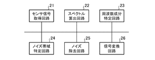
- the vital detection device 3 shown in FIG. 2 includes a sensor signal acquisition unit 11, a spectrum calculation unit 12, a frequency component identification unit 13, a noise band identification unit 14, a noise removal unit 15, and a signal conversion unit 16.
- the sensor signal acquisition unit 11 is implemented by, for example, a sensor signal acquisition circuit 21 shown in FIG.
- the sensor signal acquisition unit 11 acquires sensor signals output from the biosensor 1 .
- the sensor signal acquisition section 11 outputs the sensor signal to the spectrum calculation section 12 .
- the spectrum calculator 12 is implemented by, for example, a spectrum calculator circuit 22 shown in FIG.
- the spectrum calculator 12 calculates the frequency spectrum of the sensor signal acquired by the sensor signal acquirer 11 .
- the spectrum calculator 12 calculates the frequency spectrum by performing FFT (Fast Fourier Transform) on the sensor signal.
- Spectrum calculator 12 outputs the frequency spectrum to frequency component identifier 13 .
- the frequency component identification unit 13 is implemented by, for example, a frequency component identification circuit 23 shown in FIG.
- the frequency component identifying unit 13 selects one or more frequency components that may indicate the subject's vital signs from among the plurality of frequency components included in the frequency spectrum calculated by the spectrum calculating unit 12. identify. That is, the frequency component specifying unit 13 compares each frequency component included in the frequency spectrum with the first threshold value Th1.
- the frequency component identifying unit 13 identifies, among the plurality of frequency components, frequency components that are greater than the first threshold value Th1 as frequency components that may indicate the subject's vital signs.
- the first threshold Th 1 may be stored in the internal memory of the frequency component identifying section 13 or may be given from the outside of the vital detection device 3 .
- the frequency component identification unit 13 outputs the identified one or more frequency components to the noise removal unit 15 .
- the noise band identification unit 14 is realized by, for example, a noise band identification circuit 24 shown in FIG.
- the noise band specifying unit 14 acquires a noise signal from the noise observer 2 and specifies a noise band, which is a frequency band in which noise exists, based on the noise signal. That is, the noise band identification unit 14 acquires the vibration signal as the noise signal from the vehicle-mounted sensor 2a.
- the noise band identification unit 14 calculates the frequency spectrum of the vibration signal, and identifies the frequency band indicating vehicle vibration as the noise band from the frequency spectrum of the vibration signal.
- the noise band identifying section 14 outputs the noise band to the noise eliminating section 15 .
- the noise elimination unit 15 is realized by, for example, a noise elimination circuit 25 shown in FIG.
- the noise removal unit 15 removes frequency components included in the noise band identified by the noise band identification unit 14 among the one or more frequency components identified by the frequency component identification unit 13 .
- the noise removing unit 15 converts the frequency components remaining after removing the frequency components included in the noise band among the one or more frequency components specified by the frequency component specifying unit 13 to the signal converting unit 16. Output.
- the signal conversion unit 16 is implemented by, for example, a signal conversion circuit 26 shown in FIG.
- the signal transforming unit 16 transforms the remaining frequency components not removed by the noise removing unit 15 among the one or more frequency components specified by the frequency component specifying unit 13 into time domain signals.
- the signal transforming unit 16 transforms the remaining frequency components into a time-domain signal by performing inverse FFT on the remaining frequency components.
- a signal in the time domain corresponds to a signal obtained by removing noise from the sensor signal acquired by the sensor signal acquisition unit 11 .
- the signal converter 16 outputs the noise-removed sensor signal to the vital diagnostic device 4 or the display 5 .
- Each of the sensor signal acquisition circuit 21, the spectrum calculation circuit 22, the frequency component identification circuit 23, the noise band identification circuit 24, the noise removal circuit 25 and the signal conversion circuit 26 is, for example, a single circuit, a composite circuit, a programmed processor, Parallel-programmed processors, ASICs (Application Specific Integrated Circuits), FPGAs (Field-Programmable Gate Arrays), or combinations thereof are applicable.
- the components of the vital detection device 3 are not limited to those realized by dedicated hardware, but the vital detection device 3 may be realized by software, firmware, or a combination of software and firmware. good too.
- Software or firmware is stored as a program in a computer's memory.
- a computer means hardware that executes a program, for example, a CPU (Central Processing Unit), a central processing unit, a processing unit, an arithmetic unit, a microprocessor, a microcomputer, a processor, or a DSP (Digital Signal Processor). do.
- FIG. 4 is a hardware configuration diagram of a computer when the vital detection device 3 is implemented by software, firmware, or the like.
- the sensor signal acquisition unit 11, the spectrum calculation unit 12, the frequency component identification unit 13, the noise band identification unit 14, the noise removal unit 15, and the signal conversion unit 16 A memory 31 stores a program for causing a computer to execute the processing procedure of . Then, the processor 32 of the computer executes the program stored in the memory 31 .
- FIG. 3 shows an example in which each component of the vital detection device 3 is implemented by dedicated hardware
- FIG. 4 shows an example in which the vital detection device 3 is implemented by software, firmware, or the like.
- this is only an example, and some of the components of the vital detector 3 may be implemented by dedicated hardware, and the remaining components may be implemented by software, firmware, or the like.
- FIG. 5 is a flow chart showing a vital detection method, which is a processing procedure of the vital detection device 3 .
- the biosensor 1 senses the subject's vital signs and outputs a sensor signal indicating the sensing result to the vitals detector 3 .
- the biosensor 1 photographs the subject and senses the subject's vital signs based on the subject's image.
- the light irradiated on the skin is divided into light specularly reflected by the subject's skin, light diffusely reflected by the subject's skin, and light reflected by the subject's skin. It is divided into light scattered by Among the light scattered by the skin of the person to be measured, there is scattered light that passes through the skin, reaches the blood vessels, and then leaves the surface of the skin again. Such scattered light contains information about pulse rate. Some of the light that reaches blood vessels is absorbed by hemoglobin contained in blood.
- the biosensor 1 which is realized by video equipment, detects the pulse rate by extracting the component contained in the scattered light that changes according to the pulsation, from the luminance value of the skin surface indicated by the image of the subject. can be estimated.
- the processing itself for estimating the pulse rate from the luminance value of the skin surface is a known technique, and detailed description thereof will be omitted.
- the biosensor 1 When the biosensor 1 is realized by a radio wave sensor, the biosensor 1 irradiates the body surface of the person to be measured with microwaves and receives the reflected waves, which are the microwaves after being reflected by the body surface. Since the human body vibrates due to heartbeat or respiration, the phase of the reflected wave changes over time. The biosensor 1 can estimate the pulse rate and respiration rate by detecting the phase change of the reflected wave. Since the processing itself for estimating the pulse rate and the like from the phase change of the reflected wave is a known technology, detailed description thereof will be omitted.
- the in-vehicle sensor 2 a observes the vibration of the vehicle in which the subject is riding as noise that may be mixed in the sensor signal indicating the sensing result of the biosensor 1 .
- the in-vehicle sensor 2a outputs a vibration signal indicating vibration of the vehicle to the vital detector 3 as a noise signal.
- the sensor signal acquisition unit 11 of the vital detection device 3 acquires a sensor signal from the biosensor 1 (step ST1 in FIG. 5).
- the sensor signal contains frequency components that indicate the subject's vital signs. Further, the sensor signal may contain noise frequency components.
- the sensor signal acquisition section 11 outputs the sensor signal to the spectrum calculation section 12 .
- the spectrum calculator 12 acquires the sensor signal from the sensor signal acquirer 11 .
- the spectrum calculator 12 calculates the frequency spectrum of the sensor signal by, for example, performing FFT on the sensor signal (step ST2 in FIG. 5).
- Spectrum calculator 12 outputs the frequency spectrum to frequency component identifier 13 .
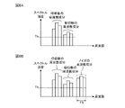
- FIG. 6 is an explanatory diagram showing an example of the frequency spectrum calculated by the spectrum calculator 12.
- FIG. 6A shows a frequency spectrum containing frequency components of respiration rate and pulse rate as frequency components of the subject's vital signs.
- FIG. 6B shows a frequency spectrum containing frequency components of noise in addition to frequency components of respiration rate and pulse rate.
- the horizontal axis is frequency
- the vertical axis is spectrum intensity.
- the frequency component identifying section 13 acquires the frequency spectrum from the spectrum calculating section 12 .
- the frequency component identifying unit 13 identifies one or more frequency components that may indicate the subject's vital signs among the plurality of frequency components included in the frequency spectrum (step ST3). That is, the frequency component specifying unit 13 compares each frequency component included in the frequency spectrum with the first threshold value Th1.
- the frequency component identifying unit 13 identifies, among the plurality of frequency components, frequency components that are greater than the first threshold value Th1 as frequency components that may indicate the subject's vital signs.
- the frequency component identifying unit 13 identifies the frequency component of the respiration rate, the frequency component of the pulse rate, and the frequency component of noise as frequency components that may indicate the vital signs of the subject. are identified.
- the frequency component identification unit 13 outputs the identified one or more frequency components to the noise removal unit 15 .
- the noise band specifying unit 14 acquires a vibration signal as a noise signal from the vehicle-mounted sensor 2a.
- the noise band specifying unit 14 calculates the frequency spectrum of the vibration signal by, for example, performing FFT on the vibration signal.
- the noise band identification unit 14 identifies a frequency band indicating vibration of the vehicle as a noise band from the frequency spectrum of the vibration signal (step ST4 in FIG. 5).
- the noise band identifying section 14 outputs the noise band to the noise eliminating section 15 .
- the noise band identification processing by the noise band identification unit 14 will be specifically described below.
- the noise band specifying unit 14 calculates the frequency spectrum of the vibration signal by, for example, performing FFT on the vibration signal.
- the noise band identifying unit 14 compares one or more frequency components included in the frequency spectrum of the vibration signal with the second threshold Th2.
- the noise band specifying unit 14 determines that, among one or more frequency components included in the frequency spectrum of the vibration signal, a frequency band of frequency components larger than the second threshold value Th2 indicates the vibration of the vehicle. , that is, the noise band.
- the second threshold Th 2 may be stored in the internal memory of the noise band identification unit 14 or may be given from the outside of the vital detection device 3 .
- the frequency band FB is the noise band.
- the noise removal unit 15 acquires one or more frequency components that may indicate the subject's vital signs from the frequency component identification unit 13 .
- the noise removal unit 15 acquires the noise band from the noise band identification unit 14 .
- the noise removal section 15 removes frequency components included in the noise band among one or more frequency components that may indicate the subject's vital signs (step ST5 in FIG. 5).
- the noise removal unit 15 removes the remaining frequency components from the one or more frequency components that may indicate vital signs even after the frequency components included in the noise band are removed, and the signal conversion unit 16 removes the remaining frequency components.
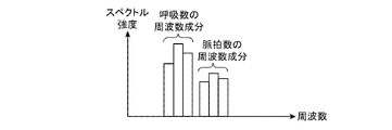
- output to FIG. 7 is an explanatory diagram showing frequency components remaining even after the frequency components included in the noise band are removed by the noise removing unit 15.
- the noise which is the vibration of the vehicle, is removed, leaving the respiration rate frequency component and the pulse rate frequency component.
- the horizontal axis is frequency
- the vertical axis is spectrum intensity.
- the signal converter 16 acquires the remaining frequency components from the noise remover 15 .
- the signal transforming unit 16 transforms the remaining frequency components into a time-domain signal by performing inverse FFT on the remaining frequency components (step ST6 in FIG. 5).
- a signal in the time domain corresponds to a signal obtained by removing noise from the sensor signal acquired by the sensor signal acquisition unit 11 .
- the signal converter 16 outputs the noise-removed sensor signal to the vital diagnostic device 4 or the display 5 .
- the vital diagnosis device 4 diagnoses the subject based on the vital sign indicated by the noise-removed sensor signal.
- the display 5 causes the display to display the vital sign indicated by the noise-removed sensor signal.
- the sensor signal acquisition unit 11 acquires the sensor signal indicating the sensing result of the biosensor 1 that senses the vital signs of the subject, and the frequency of the sensor signal acquired by the sensor signal acquisition unit 11
- a spectrum calculator 12 that calculates a spectrum, and one or more frequency components that may indicate the subject's vital signs among a plurality of frequency components included in the frequency spectrum calculated by the spectrum calculator 12.
- the noise The noise band identifying unit 14 that identifies the noise band that is the frequency band in which the noise identified by the noise band identifying unit 14 among the one or more frequency components identified by the frequency component identifying unit 13
- the vital detection device 3 is configured to include a noise removal unit 15 for removing frequency components included in the band. Therefore, the vitals detection device 3 can remove frequency components of noise having magnitudes equal to or less than the assumed maximum value and having magnitudes equal to or greater than the assumed minimum value.
- the noise band identification unit 17 acquires, as a noise signal, a body motion signal indicating the body motion of the person being measured observed by the person-to-be-measured observer 2b, and determines noise based on the body motion signal.
- the vitals detection device 3 that identifies the band will be described.
- FIG. 8 is a configuration diagram showing an in-vehicle device including the vitals detection device 3 according to Embodiment 2. As shown in FIG. In FIG. 8, the same reference numerals as those in FIG. 1 denote the same or corresponding parts, so description thereof will be omitted.
- the vital detection device 3 shown in FIG. 8 is mounted on an in-vehicle device.
- the vitals detection device 3 is not limited to being mounted on an in-vehicle device, and may be one installed in a hospital, public facility, or the like.
- the noise observer 2 includes a person-to-be-measured observer 2b.
- the person-to-be-measured observer 2b is realized by, for example, video equipment.
- the person-to-be-measured observer 2b captures an image of the person to be measured, and observes the body movement of the person to be measured as noise that may be mixed in the sensor signal based on the image data of the person to be measured.
- the person-to-be-measured observer 2 b outputs a body motion signal indicating the body movement of the person to be measured to the vital detector 3 .
- FIG. 9 is a configuration diagram of a vital detection device 3 according to Embodiment 2.
- FIG. 10 is a hardware configuration diagram showing hardware of the vital detection device 3 according to the second embodiment.
- the same reference numerals as those in FIGS. 2 and 3 denote the same or corresponding parts, so description thereof will be omitted.
- the vital detection device 3 includes a sensor signal acquisition unit 11 , a spectrum calculation unit 12 , a frequency component identification unit 13 , a noise band identification unit 17 , a noise removal unit 15 and a signal conversion unit 16 .
- the noise band identification unit 17 is implemented by, for example, a noise band identification circuit 27 shown in FIG.
- the noise band specifying unit 17 acquires a noise signal from the noise observer 2 and specifies a noise band, which is a frequency band in which noise exists, from the noise signal. That is, the noise band specifying unit 17 acquires the body motion signal as a noise signal from the subject observer 2b.
- the noise band specifying unit 17 specifies a frequency band indicating body motion as a noise band based on the body motion signal.
- the noise band identifying section 17 outputs the noise band to the noise eliminating section 15 .
- each of the sensor signal acquisition unit 11, the spectrum calculation unit 12, the frequency component identification unit 13, the noise band identification unit 17, the noise removal unit 15, and the signal conversion unit 16, which are components of the vital detection device 3, is shown in FIG. 10 is assumed to be realized by dedicated hardware. That is, it is assumed that the vital detection device 3 is realized by the sensor signal acquisition circuit 21, the spectrum calculation circuit 22, the frequency component identification circuit 23, the noise band identification circuit 27, the noise removal circuit 25, and the signal conversion circuit 26. .
- Each of the sensor signal acquisition circuit 21, the spectrum calculation circuit 22, the frequency component identification circuit 23, the noise band identification circuit 27, the noise removal circuit 25 and the signal conversion circuit 26 is, for example, a single circuit, a composite circuit, a programmed processor, This includes parallel programmed processors, ASICs, FPGAs, or combinations thereof.
- the components of the vital detection device 3 are not limited to those realized by dedicated hardware, but the vital detection device 3 may be realized by software, firmware, or a combination of software and firmware. good too.
- the vital detection device 3 is realized by software, firmware, etc.
- the sensor signal acquisition unit 11, the spectrum calculation unit 12, the frequency component identification unit 13, the noise band identification unit 17, the noise removal unit 15, and the signal conversion unit 16 4 is stored in the memory 31 shown in FIG.
- the processor 32 shown in FIG. 4 executes the program stored in the memory 31 .
- FIG. 10 shows an example in which each component of the vital detection device 3 is implemented by dedicated hardware
- FIG. 4 shows an example in which the vital detection device 3 is implemented by software, firmware, or the like.
- this is only an example, and some of the components of the vital detector 3 may be implemented by dedicated hardware, and the remaining components may be implemented by software, firmware, or the like.
- the person-to-be-measured observer 2b captures an image of the person to be measured, and based on the image data of the person to be measured, detects the noise that may be mixed in the sensor signal indicating the sensing result of the biosensor 1. observe the body movements of The person-to-be-measured observer 2 b outputs a body motion signal indicating the body movement of the person to be measured to the vital detector 3 . Since the human body vibrates due to heartbeat or respiration, the body movement of the subject can be observed by the subject monitor 2b monitoring the image data of the subject.
- the noise band identification unit 17 acquires a body motion signal as a noise signal from the subject observer 2b.
- the noise band specifying unit 17 specifies a frequency band indicating body motion as a noise band based on the body motion signal. That is, the noise band identification unit 17 measures the amount of change in a certain part of the person to be measured per certain period of time based on the body motion signal. As a certain site, the subject's head, chest, arm, or the like can be considered.
- the noise band specifying unit 17 specifies a frequency band indicating the body motion of the person to be measured from the amount of change per fixed time.
- the processing itself for identifying the frequency band indicating body motion from the amount of change per fixed time is a known technique, and therefore detailed description thereof will be omitted.
- the noise band identifying section 17 outputs the noise band to the noise eliminating section 15 .
- the noise band specifying unit 17 acquires, as a noise signal, a body motion signal indicating the body motion of the person being measured observed by the person-to-be-measured observer 2b, and based on the body motion signal , the vital detector 3 shown in FIG. 9 is configured to identify the noise band. Therefore, the vital detection device 3 shown in FIG. 9, like the vital detection device 3 shown in FIG. components can be removed.
- the noise band identification unit 14 detects noise that may be mixed in the sensor signal indicating the sensing result of the biosensor 1 based on the vibration signal output from the vehicle-mounted sensor 2a. , the vibration of the vehicle in which the subject is riding is observed.
- the noise band identification unit 17 detects the noise that may be mixed in the sensor signal based on the body movement signal output from the measurement subject observation device 2b. Observing a person's body movements.
- the noise observer 2 of the in-vehicle device includes, for example, a noise measuring device that measures the frequency band of noise output from a power supply or the like mounted on the vehicle, and the noise band specifying unit 14
- the noise band identification unit 17 may acquire the noise frequency band measured by the noise measuring device as the noise band.
- the present disclosure is suitable for a vital detection device and a vital detection method.
- the present disclosure is suitable for an in-vehicle device that includes a vital detection device.
Landscapes
- Health & Medical Sciences (AREA)
- Life Sciences & Earth Sciences (AREA)
- Engineering & Computer Science (AREA)
- Signal Processing (AREA)
- Physics & Mathematics (AREA)
- General Health & Medical Sciences (AREA)
- Veterinary Medicine (AREA)
- Heart & Thoracic Surgery (AREA)
- Medical Informatics (AREA)
- Molecular Biology (AREA)
- Surgery (AREA)
- Animal Behavior & Ethology (AREA)
- Pathology (AREA)
- Public Health (AREA)
- Biomedical Technology (AREA)
- Biophysics (AREA)
- Artificial Intelligence (AREA)
- Computer Vision & Pattern Recognition (AREA)
- Physiology (AREA)
- Psychiatry (AREA)
- Mathematical Physics (AREA)
- Measuring Pulse, Heart Rate, Blood Pressure Or Blood Flow (AREA)
- Measurement Of The Respiration, Hearing Ability, Form, And Blood Characteristics Of Living Organisms (AREA)
- Measuring And Recording Apparatus For Diagnosis (AREA)
Abstract
Description
図1は、実施の形態1に係るバイタル検出装置3を含む車載装置を示す構成図である。
図1に示す車載装置は、生体センサ1、ノイズ観測器2、バイタル検出装置3、バイタル診断装置4及び表示器5を備えている。
図1に示すバイタル検出装置3は、車載装置に搭載されている。バイタル検出装置3は、車載装置に搭載されているものに限るものではなく、病院又は公共施設等に設置されているものであってもよい。
生体センサ1は、例えば、映像機器、又は、電波式センサによって実現される。
生体センサ1は、被測定者のバイタルサインをセンシングし、センシング結果を示すセンサ信号をバイタル検出装置3に出力する。
ノイズ観測器2は、ノイズの観測結果を示すノイズ信号をバイタル検出装置3に出力する。
図1に示すバイタル検出装置3では、ノイズ観測器2が車載センサ2aを含んでいる。
車載センサ2aは、車両のヨーレートセンサ、又は、加速度センサ等によって実現される。
車載センサ2aは、センサ信号に混入している可能性のあるノイズとして、被測定者が乗車している車両の振動を観測する。
車載センサ2aは、ノイズ信号として、車両の振動を示す振動信号をバイタル検出装置3に出力する。
なお、ヨーレートセンサは、車両の進行方向を検出するセンサである。車両は、進行方向の変化に伴って振動する。したがって、ヨーレートセンサのセンシング結果を解析することで、車両の振動を観測することができる。
加速度センサは、車両の加速度を検出するセンサである。車両は、加速度の変化に伴って振動する。したがって、加速度センサのセンシング結果を解析することで、車両の振動を観測することができる。
バイタル診断装置4は、バイタル検出装置3により検出されたバイタルサインに基づいて、被測定者を診断する。
表示器5は、バイタル検出装置3により検出された被測定者のバイタルサインをディスプレイに表示させる。
図3は、実施の形態1に係るバイタル検出装置3のハードウェアを示すハードウェア構成図である。
図2に示すバイタル検出装置3は、センサ信号取得部11、スペクトル算出部12、周波数成分特定部13、ノイズ帯域特定部14、ノイズ除去部15及び信号変換部16を備えている。
センサ信号取得部11は、例えば、図3に示すセンサ信号取得回路21によって実現される。
センサ信号取得部11は、生体センサ1から出力されたセンサ信号を取得する。
センサ信号取得部11は、センサ信号をスペクトル算出部12に出力する。
スペクトル算出部12は、センサ信号取得部11により取得されたセンサ信号の周波数スペクトルを算出する。例えば、スペクトル算出部12は、センサ信号をFFT(Fast Fourier Transform)することによって、周波数スペクトルを算出する。
スペクトル算出部12は、周波数スペクトルを周波数成分特定部13に出力する。
周波数成分特定部13は、スペクトル算出部12により算出された周波数スペクトルに含まれている複数の周波数成分の中で、被測定者のバイタルサインを示している可能性がある1つ以上の周波数成分を特定する。
即ち、周波数成分特定部13は、周波数スペクトルに含まれているそれぞれの周波数成分と第1の閾値Th1とを比較する。周波数成分特定部13は、複数の周波数成分の中で、第1の閾値Th1よりも大きな周波数成分を、被測定者のバイタルサインを示している可能性がある周波数成分として特定する。第1の閾値Th1は、周波数成分特定部13の内部メモリに格納されていてもよいし、バイタル検出装置3の外部から与えられるものであってもよい。
周波数成分特定部13は、特定した1つ以上の周波数成分をノイズ除去部15に出力する。
ノイズ帯域特定部14は、ノイズ観測器2からノイズ信号を取得し、ノイズ信号に基づいて、ノイズが存在している周波数帯域であるノイズ帯域を特定する。
即ち、ノイズ帯域特定部14は、車載センサ2aから、ノイズ信号として振動信号を取得する。ノイズ帯域特定部14は、振動信号の周波数スペクトルを算出し、振動信号の周波数スペクトルから、ノイズ帯域として、車両の振動を示す周波数の帯域を特定する。
ノイズ帯域特定部14は、ノイズ帯域をノイズ除去部15に出力する。
ノイズ除去部15は、周波数成分特定部13により特定された1つ以上の周波数成分の中で、ノイズ帯域特定部14により特定されたノイズ帯域に含まれている周波数成分を除去する。
ノイズ除去部15は、周波数成分特定部13により特定された1つ以上の周波数成分の中で、ノイズ帯域に含まれている周波数成分を除去しても残っている周波数成分を信号変換部16に出力する。
信号変換部16は、周波数成分特定部13により特定された1つ以上の周波数成分の中で、ノイズ除去部15により除去されずに残っている周波数成分を時間領域の信号に変換する。例えば、信号変換部16は、残っている周波数成分を逆FFTすることによって、残っている周波数成分を時間領域の信号に変換する。時間領域の信号は、センサ信号取得部11により取得されたセンサ信号から、ノイズが除去された信号に相当する。
信号変換部16は、ノイズ除去後のセンサ信号を、バイタル診断装置4又は表示器5に出力する。
センサ信号取得回路21、スペクトル算出回路22、周波数成分特定回路23、ノイズ帯域特定回路24、ノイズ除去回路25及び信号変換回路26のそれぞれは、例えば、単一回路、複合回路、プログラム化したプロセッサ、並列プログラム化したプロセッサ、ASIC(Application Specific Integrated Circuit)、FPGA(Field-Programmable Gate Array)、又は、これらを組み合わせたものが該当する。
ソフトウェア又はファームウェアは、プログラムとして、コンピュータのメモリに格納される。コンピュータは、プログラムを実行するハードウェアを意味し、例えば、CPU(Central Processing Unit)、中央処理装置、処理装置、演算装置、マイクロプロセッサ、マイクロコンピュータ、プロセッサ、あるいは、DSP(Digital Signal Processor)が該当する。
バイタル検出装置3が、ソフトウェア又はファームウェア等によって実現される場合、センサ信号取得部11、スペクトル算出部12、周波数成分特定部13、ノイズ帯域特定部14、ノイズ除去部15及び信号変換部16におけるそれぞれの処理手順をコンピュータに実行させるためのプログラムがメモリ31に格納される。そして、コンピュータのプロセッサ32がメモリ31に格納されているプログラムを実行する。
図5は、バイタル検出装置3の処理手順であるバイタル検出方法を示すフローチャートである。
生体センサ1は、被測定者のバイタルサインをセンシングし、センシング結果を示すセンサ信号をバイタル検出装置3に出力する。
被測定者の肌に光が照射されると、肌に照射された光は、被測定者の肌で鏡面反射する光と、被測定者の肌で拡散反射する光と、被測定者の肌で散乱する光とに分かれる。
被測定者の肌で散乱する光の中には、肌を透過して血管に到達したのち、再度、肌の表面から出ていく散乱光がある。このような散乱光は、脈拍数に関する情報を含んでいる。
血管に到達した光の一部は、血液に含まれているヘモグロビンに吸収される。血液に含まれているヘモグロビンの量は、血流の脈動によって変化するため、血管内で吸収される光の量も脈動に応じて変化する。したがって、散乱光は、脈動に応じて変化する成分を有している。
映像機器によって実現されている生体センサ1は、被測定者の映像が示す肌表面の輝度値から、散乱光に含まれている、脈動に応じて変化する成分を抽出することで、脈拍数を推定することができる。肌表面の輝度値から脈拍数を推定する処理自体は、公知の技術であるため詳細な説明を省略する。
車載センサ2aは、ノイズ信号として、車両の振動を示す振動信号をバイタル検出装置3に出力する。
センサ信号取得部11は、センサ信号をスペクトル算出部12に出力する。
スペクトル算出部12は、例えば、センサ信号をFFTすることによって、センサ信号の周波数スペクトルを算出する(図5のステップST2)。
スペクトル算出部12は、周波数スペクトルを周波数成分特定部13に出力する。
図6は、スペクトル算出部12により算出される周波数スペクトルの一例を示す説明図である。
図6Aは、被測定者のバイタルサインの周波数成分として、呼吸数の周波数成分と脈拍数の周波数成分とを含んでいる周波数スペクトルを示している。
図6Bは、呼吸数の周波数成分と脈拍数の周波数成分とのほかに、ノイズの周波数成分を含んでいる周波数スペクトルを示している。
図6A及び図6Bにおいて、横軸は周波数、縦軸はスペクトル強度である。
車両が振動している場合、車両の振動がノイズとしてセンサ信号に混入し、図6Bに示すようなノイズの周波数成分が周波数スペクトルに現れることがある。
周波数成分特定部13は、周波数スペクトルに含まれている複数の周波数成分の中で、被測定者のバイタルサインを示している可能性がある1つ以上の周波数成分を特定する(図5のステップST3)。
即ち、周波数成分特定部13は、周波数スペクトルに含まれているそれぞれの周波数成分と第1の閾値Th1とを比較する。周波数成分特定部13は、複数の周波数成分の中で、第1の閾値Th1よりも大きな周波数成分を、被測定者のバイタルサインを示している可能性がある周波数成分として特定する。
図6Bの例では、周波数成分特定部13が、被測定者のバイタルサインを示している可能性がある周波数成分として、呼吸数の周波数成分と、脈拍数の周波数成分と、ノイズの周波数成分とを特定している。
周波数成分特定部13は、特定した1つ以上の周波数成分をノイズ除去部15に出力する。
ノイズ帯域特定部14は、例えば、振動信号をFFTすることによって、振動信号の周波数スペクトルを算出する。
ノイズ帯域特定部14は、振動信号の周波数スペクトルから、ノイズ帯域として、車両の振動を示す周波数の帯域を特定する(図5のステップST4)。
ノイズ帯域特定部14は、ノイズ帯域をノイズ除去部15に出力する。
ノイズ帯域特定部14は、例えば、振動信号をFFTすることによって、振動信号の周波数スペクトルを算出する。
ノイズ帯域特定部14は、振動信号の周波数スペクトルに含まれている1つ以上の周波数成分と第2の閾値Th2とを比較する。
ノイズ帯域特定部14は、振動信号の周波数スペクトルに含まれている1つ以上の周波数成分のうち、第2の閾値Th2よりも大きな周波数成分の周波数帯域が、車両の振動を示している周波数の帯域、即ち、ノイズ帯域であると判断する。第2の閾値Th2は、ノイズ帯域特定部14の内部メモリに格納されていてもよいし、バイタル検出装置3の外部から与えられるものであってもよい。
図6Bの例では、周波数帯域FBが、ノイズ帯域である。
ノイズ除去部15は、ノイズ帯域特定部14から、ノイズ帯域を取得する。
ノイズ除去部15は、被測定者のバイタルサインを示している可能性がある1つ以上の周波数成分の中で、ノイズ帯域に含まれている周波数成分を除去する(図5のステップST5)。
ノイズ除去部15は、バイタルサインを示している可能性がある1つ以上の周波数成分の中で、ノイズ帯域に含まれている周波数成分を除去しても残っている周波数成分を信号変換部16に出力する。
図7は、ノイズ除去部15によって、ノイズ帯域に含まれている周波数成分が除去されても残っている周波数成分を示す説明図である。
図7の例では、車両の振動であるノイズが除去され、呼吸数の周波数成分と脈拍数の周波数成分とが残っている。
図7において、横軸は周波数、縦軸はスペクトル強度である。
信号変換部16は、残っている周波数成分を逆FFTすることによって、残っている周波数成分を時間領域の信号に変換する(図5のステップST6)。時間領域の信号は、センサ信号取得部11により取得されたセンサ信号から、ノイズが除去された信号に相当する。
信号変換部16は、ノイズ除去後のセンサ信号を、バイタル診断装置4又は表示器5に出力する。
表示器5は、バイタル検出装置3からノイズ除去後のセンサ信号を受けると、ノイズ除去後のセンサ信号が示すバイタルサインをディスプレイに表示させる。
実施の形態2では、ノイズ帯域特定部17が、ノイズ信号として、被測定者観測器2bにより観測された被測定者の体動を示す体動信号を取得し、体動信号に基づいて、ノイズ帯域を特定するバイタル検出装置3について説明する。
図8に示す車載装置は、生体センサ1、ノイズ観測器2、バイタル検出装置3、バイタル診断装置4及び表示器5を備えている。
図8に示すバイタル検出装置3は、車載装置に搭載されている。バイタル検出装置3は、車載装置に搭載されているものに限るものではなく、病院又は公共施設等に設置されているものであってもよい。
図8に示すバイタル検出装置3では、ノイズ観測器2が被測定者観測器2bを含んでいる。
被測定者観測器2bは、例えば、映像機器によって実現される。
被測定者観測器2bは、被測定者を撮像し、被測定者の映像データに基づいて、センサ信号に混入している可能性のあるノイズとして、被測定者の体動を観測する。
被測定者観測器2bは、被測定者の体動を示す体動信号をバイタル検出装置3に出力する。
図10は、実施の形態2に係るバイタル検出装置3のハードウェアを示すハードウェア構成図である。
図9及び図10において、図2及び図3と同一符号は同一又は相当部分を示すので説明を省略する。
ノイズ帯域特定部17は、例えば、図10に示すノイズ帯域特定回路27によって実現される。
ノイズ帯域特定部17は、ノイズ観測器2からノイズ信号を取得し、ノイズ信号から、ノイズが存在している周波数帯域であるノイズ帯域を特定する。
即ち、ノイズ帯域特定部17は、被測定者観測器2bから、ノイズ信号として体動信号を取得する。ノイズ帯域特定部17は、体動信号に基づいて、ノイズ帯域として、体動を示す周波数の帯域を特定する。
ノイズ帯域特定部17は、ノイズ帯域をノイズ除去部15に出力する。
センサ信号取得回路21、スペクトル算出回路22、周波数成分特定回路23、ノイズ帯域特定回路27、ノイズ除去回路25及び信号変換回路26のそれぞれは、例えば、単一回路、複合回路、プログラム化したプロセッサ、並列プログラム化したプロセッサ、ASIC、FPGA、又は、これらを組み合わせたものが該当する。
バイタル検出装置3が、ソフトウェア又はファームウェア等によって実現される場合、センサ信号取得部11、スペクトル算出部12、周波数成分特定部13、ノイズ帯域特定部17、ノイズ除去部15及び信号変換部16におけるそれぞれの処理手順をコンピュータに実行させるためのプログラムが図4に示すメモリ31に格納される。そして、図4に示すプロセッサ32がメモリ31に格納されているプログラムを実行する。
被測定者観測器2bは、被測定者の体動を示す体動信号をバイタル検出装置3に出力する。
人の体は、心拍、又は、呼吸によって振動しているため、被測定者観測器2bが、被測定者の映像データを監視すれば、被測定者の体動を観測することができる。
ノイズ帯域特定部17は、体動信号に基づいて、ノイズ帯域として、体動を示す周波数の帯域を特定する。
即ち、ノイズ帯域特定部17は、体動信号に基づいて、被測定者の或る部位の一定時間当りの変化量を測定する。或る部位としては、被測定者の頭、胸、又は、腕等が考えられる。
ノイズ帯域特定部17は、一定時間当りの変化量から、被測定者の体動を示す周波数の帯域を特定する。一定時間当りの変化量から体動を示す周波数の帯域を特定する処理自体は、公知の技術であるため詳細な説明を省略する。
ノイズ帯域特定部17は、ノイズ帯域をノイズ除去部15に出力する。
しかし、これらは一例に過ぎず、車載装置のノイズ観測器2が、例えば、車両に実装されている電源等から出力されるノイズの周波数帯域を測定するノイズ測定器を備え、ノイズ帯域特定部14、又は、ノイズ帯域特定部17が、ノイズ帯域として、当該ノイズ測定器により測定されたノイズの周波数帯域を取得するようにしてもよい。
本開示は、バイタル検出装置を備える車載装置に適している。
Claims (6)
- 被測定者のバイタルサインをセンシングする生体センサのセンシング結果を示すセンサ信号を取得するセンサ信号取得部と、
前記センサ信号取得部により取得されたセンサ信号の周波数スペクトルを算出するスペクトル算出部と、
前記スペクトル算出部により算出された周波数スペクトルに含まれている複数の周波数成分の中で、前記被測定者のバイタルサインを示している可能性がある1つ以上の周波数成分を特定する周波数成分特定部と、
前記生体センサのセンシング結果を示すセンサ信号に混入している可能性のあるノイズを観測するノイズ観測器の観測結果を示すノイズ信号から、前記ノイズが存在している周波数帯域であるノイズ帯域を特定するノイズ帯域特定部と、
前記周波数成分特定部により特定された1つ以上の周波数成分の中で、前記ノイズ帯域特定部により特定されたノイズ帯域に含まれている周波数成分を除去するノイズ除去部と
を備えたバイタル検出装置。 - 前記ノイズ観測器が、前記生体センサのセンシング結果を示すセンサ信号に混入している可能性のあるノイズとして、前記被測定者が乗車している車両の振動を観測する車載センサを含んでおり、
前記ノイズ帯域特定部は、前記ノイズ信号として、前記車載センサにより観測された車両の振動を示す振動信号を取得し、前記振動信号に基づいて、前記ノイズ帯域を特定することを特徴とする請求項1記載のバイタル検出装置。 - 前記ノイズ観測器が、前記生体センサのセンシング結果を示すセンサ信号に混入している可能性のあるノイズとして、前記被測定者の体動を観測する被測定者観測器を含んでおり、
前記ノイズ帯域特定部は、前記ノイズ信号として、前記被測定者観測器により観測された被測定者の体動を示す体動信号を取得し、前記体動信号に基づいて、前記ノイズ帯域を特定することを特徴とする請求項1記載のバイタル検出装置。 - 前記周波数成分特定部により特定された1つ以上の周波数成分の中で、前記ノイズ除去部により除去されずに残っている周波数成分を時間領域の信号に変換する信号変換部を備えたことを特徴とする請求項1記載のバイタル検出装置。
- センサ信号取得部が、被測定者のバイタルサインをセンシングする生体センサのセンシング結果を示すセンサ信号を取得し、
スペクトル算出部が、前記センサ信号取得部により取得されたセンサ信号の周波数スペクトルを算出し、
周波数成分特定部が、前記スペクトル算出部により算出された周波数スペクトルに含まれている複数の周波数成分の中で、前記被測定者のバイタルサインを示している可能性がある1つ以上の周波数成分を特定し、
ノイズ帯域特定部が、前記生体センサのセンシング結果を示すセンサ信号に混入している可能性のあるノイズを観測するノイズ観測器の観測結果を示すノイズ信号から、前記ノイズが存在している周波数帯域であるノイズ帯域を特定し、
ノイズ除去部が、前記周波数成分特定部により特定された1つ以上の周波数成分の中で、前記ノイズ帯域特定部により特定されたノイズ帯域に含まれている周波数成分を除去する
バイタル検出方法。 - 被測定者のバイタルサインをセンシングする生体センサと、
前記生体センサのセンシング結果を示すセンサ信号に混入している可能性のあるノイズを観測するノイズ観測器と、
請求項1から請求項4のうちのいずれか1項記載のバイタル検出装置と
を備えた車載装置。
Priority Applications (4)
| Application Number | Priority Date | Filing Date | Title |
|---|---|---|---|
| PCT/JP2021/012896 WO2022201496A1 (ja) | 2021-03-26 | 2021-03-26 | バイタル検出装置、バイタル検出方法及び車載装置 |
| US18/276,984 US20240115208A1 (en) | 2021-03-26 | 2021-03-26 | Vital sign detection device, vital sign detection method, and automotive device |
| JP2023508373A JP7588712B2 (ja) | 2021-03-26 | 2021-03-26 | バイタル検出装置、バイタル検出方法及び車載装置 |
| DE112021007400.8T DE112021007400T5 (de) | 2021-03-26 | 2021-03-26 | Lebenszeichenerkennungsvorrichtung, Lebenszeichenerkennungsverfahren und Automobilvorrichtung |
Applications Claiming Priority (1)
| Application Number | Priority Date | Filing Date | Title |
|---|---|---|---|
| PCT/JP2021/012896 WO2022201496A1 (ja) | 2021-03-26 | 2021-03-26 | バイタル検出装置、バイタル検出方法及び車載装置 |
Publications (1)
| Publication Number | Publication Date |
|---|---|
| WO2022201496A1 true WO2022201496A1 (ja) | 2022-09-29 |
Family
ID=83396715
Family Applications (1)
| Application Number | Title | Priority Date | Filing Date |
|---|---|---|---|
| PCT/JP2021/012896 Ceased WO2022201496A1 (ja) | 2021-03-26 | 2021-03-26 | バイタル検出装置、バイタル検出方法及び車載装置 |
Country Status (4)
| Country | Link |
|---|---|
| US (1) | US20240115208A1 (ja) |
| JP (1) | JP7588712B2 (ja) |
| DE (1) | DE112021007400T5 (ja) |
| WO (1) | WO2022201496A1 (ja) |
Citations (2)
| Publication number | Priority date | Publication date | Assignee | Title |
|---|---|---|---|---|
| US20080071177A1 (en) * | 2005-04-28 | 2008-03-20 | Pioneer Corporation | Bioinformation Sensor |
| JP2016202603A (ja) * | 2015-04-23 | 2016-12-08 | セイコーエプソン株式会社 | 生体情報処理システム、プログラム、生体情報処理システムの制御方法 |
Family Cites Families (2)
| Publication number | Priority date | Publication date | Assignee | Title |
|---|---|---|---|---|
| JP6373450B1 (ja) | 2017-05-23 | 2018-08-15 | 三菱電機株式会社 | 生体測定装置 |
| JP6967979B2 (ja) | 2018-01-22 | 2021-11-17 | フォルシアクラリオン・エレクトロニクス株式会社 | 生体情報検出装置 |
-
2021
- 2021-03-26 WO PCT/JP2021/012896 patent/WO2022201496A1/ja not_active Ceased
- 2021-03-26 JP JP2023508373A patent/JP7588712B2/ja active Active
- 2021-03-26 US US18/276,984 patent/US20240115208A1/en active Pending
- 2021-03-26 DE DE112021007400.8T patent/DE112021007400T5/de active Pending
Patent Citations (2)
| Publication number | Priority date | Publication date | Assignee | Title |
|---|---|---|---|---|
| US20080071177A1 (en) * | 2005-04-28 | 2008-03-20 | Pioneer Corporation | Bioinformation Sensor |
| JP2016202603A (ja) * | 2015-04-23 | 2016-12-08 | セイコーエプソン株式会社 | 生体情報処理システム、プログラム、生体情報処理システムの制御方法 |
Also Published As
| Publication number | Publication date |
|---|---|
| DE112021007400T5 (de) | 2024-02-08 |
| JPWO2022201496A1 (ja) | 2022-09-29 |
| US20240115208A1 (en) | 2024-04-11 |
| JP7588712B2 (ja) | 2024-11-22 |
Similar Documents
| Publication | Publication Date | Title |
|---|---|---|
| JP5915757B2 (ja) | 脈波検出方法、脈波検出装置及び脈波検出プログラム | |
| JP5333427B2 (ja) | 心拍数検出装置、心拍数検出方法、およびプログラム | |
| US10660536B2 (en) | Wearable biometric measurement device | |
| CN106901695B (zh) | 一种生命信号提取方法及装置 | |
| CN114680865B (zh) | 具备生物体信号处理系统的医用图像摄像装置、医用摄像系统以及生物体信号处理方法 | |
| JP2004121625A (ja) | 脈波検出装置及びフーリエ変換処理装置 | |
| WO2019047365A1 (zh) | 基于医疗云平台的影像大数据分析系统及方法 | |
| KR20230161443A (ko) | Rgb 이미지로부터의 심박수 추출을 위한 방법 및 시스템 | |
| JPWO2018155384A1 (ja) | 検出装置 | |
| EP3669372A1 (en) | Ultrasound determination of dynamic air bronchogram and associated devices, systems, and methods | |
| Amidei et al. | Angels-smart steering wheel for driver safety | |
| US20200250446A1 (en) | Emotion estimating apparatus | |
| CN111345799A (zh) | 生命体征测量方法和装置 | |
| JP7588712B2 (ja) | バイタル検出装置、バイタル検出方法及び車載装置 | |
| Smith et al. | Cranial accelerometry can detect cerebral vasospasm caused by subarachnoid hemorrhage | |
| KR102493242B1 (ko) | 인공지능 학습을 통해 광용적맥파로부터 대동맥판막협착증 및 기타 심혈관 질환 위험도를 판단하는 방법 및 시스템 | |
| US20150011913A1 (en) | Determination device, determination method, and computer program product | |
| RU2682996C1 (ru) | Способ определения функционального состояния водителя автомобиля в рейсе по тремору рук | |
| WO2024123389A1 (en) | System and methods for detection of subjects vitals and physiological symptoms via non-contact methods | |
| KR102483149B1 (ko) | 머신러닝을 활용한 경동맥 협착증 판별을 위한 정보제공 방법 | |
| JP5419157B2 (ja) | 脳波測定装置および脳波測定方法 | |
| EP3595510B1 (en) | Device, system and method for determining a tissue characteristic of a subject | |
| Moya-Albor et al. | Challenges and Advances in Digital Processing of Fetal Phonocardiography Signal: A Review | |
| Wang et al. | Heart rate estimation algorithm for radar signals based on ResNet18 and MobileViT | |
| CN113710150A (zh) | 脉搏数检测装置以及脉搏数检测程序 |
Legal Events
| Date | Code | Title | Description |
|---|---|---|---|
| 121 | Ep: the epo has been informed by wipo that ep was designated in this application |
Ref document number: 21933101 Country of ref document: EP Kind code of ref document: A1 |
|
| ENP | Entry into the national phase |
Ref document number: 2023508373 Country of ref document: JP Kind code of ref document: A |
|
| WWE | Wipo information: entry into national phase |
Ref document number: 18276984 Country of ref document: US |
|
| WWE | Wipo information: entry into national phase |
Ref document number: 112021007400 Country of ref document: DE |
|
| 122 | Ep: pct application non-entry in european phase |
Ref document number: 21933101 Country of ref document: EP Kind code of ref document: A1 |