WO2022201468A1 - Blower device - Google Patents
Blower device Download PDFInfo
- Publication number
- WO2022201468A1 WO2022201468A1 PCT/JP2021/012710 JP2021012710W WO2022201468A1 WO 2022201468 A1 WO2022201468 A1 WO 2022201468A1 JP 2021012710 W JP2021012710 W JP 2021012710W WO 2022201468 A1 WO2022201468 A1 WO 2022201468A1
- Authority
- WO
- WIPO (PCT)
- Prior art keywords
- impeller
- bell mouth
- main plate
- air
- downstream
- Prior art date
Links
- 230000003014 reinforcing effect Effects 0.000 claims description 10
- 238000011144 upstream manufacturing Methods 0.000 claims description 10
- 239000003507 refrigerant Substances 0.000 description 19
- 230000000052 comparative effect Effects 0.000 description 13
- 238000005057 refrigeration Methods 0.000 description 12
- 238000007664 blowing Methods 0.000 description 6
- 238000010586 diagram Methods 0.000 description 6
- 230000003068 static effect Effects 0.000 description 5
- XLYOFNOQVPJJNP-UHFFFAOYSA-N water Substances O XLYOFNOQVPJJNP-UHFFFAOYSA-N 0.000 description 5
- 230000002093 peripheral effect Effects 0.000 description 4
- 229920002430 Fibre-reinforced plastic Polymers 0.000 description 3
- 238000001816 cooling Methods 0.000 description 3
- 239000011151 fibre-reinforced plastic Substances 0.000 description 3
- 239000007788 liquid Substances 0.000 description 3
- 229910000838 Al alloy Inorganic materials 0.000 description 2
- 238000009787 hand lay-up Methods 0.000 description 2
- 238000010438 heat treatment Methods 0.000 description 2
- 238000012986 modification Methods 0.000 description 2
- 230000004048 modification Effects 0.000 description 2
- 238000000465 moulding Methods 0.000 description 2
- FYYHWMGAXLPEAU-UHFFFAOYSA-N Magnesium Chemical compound [Mg] FYYHWMGAXLPEAU-UHFFFAOYSA-N 0.000 description 1
- 229910000831 Steel Inorganic materials 0.000 description 1
- 238000013459 approach Methods 0.000 description 1
- 230000007547 defect Effects 0.000 description 1
- 238000009434 installation Methods 0.000 description 1
- 239000011810 insulating material Substances 0.000 description 1
- 230000002452 interceptive effect Effects 0.000 description 1
- 238000000034 method Methods 0.000 description 1
- 230000002787 reinforcement Effects 0.000 description 1
- 239000007921 spray Substances 0.000 description 1
- 239000010959 steel Substances 0.000 description 1
- 230000007704 transition Effects 0.000 description 1
- 238000003466 welding Methods 0.000 description 1
Images


Classifications
-
- F—MECHANICAL ENGINEERING; LIGHTING; HEATING; WEAPONS; BLASTING
- F04—POSITIVE - DISPLACEMENT MACHINES FOR LIQUIDS; PUMPS FOR LIQUIDS OR ELASTIC FLUIDS
- F04D—NON-POSITIVE-DISPLACEMENT PUMPS
- F04D29/00—Details, component parts, or accessories
- F04D29/26—Rotors specially for elastic fluids
- F04D29/28—Rotors specially for elastic fluids for centrifugal or helico-centrifugal pumps for radial-flow or helico-centrifugal pumps
- F04D29/30—Vanes
Definitions
- the embodiment of the present invention relates to a blower.
- a blower that includes a turbofan and a bell mouth on the suction side of the turbofan is known.
- the inventors have found that in a conventional air blower in which a turbofan shroud is arranged near the bell mouth, a vortex is generated on the back side of the bell mouth (inside the housing) and in the radially outer region of the shroud. found to occur. This vortex reduces the amount of air drawn by the blower.
- an object of the present invention is to provide a blower capable of efficiently sucking air from a bell mouth and blowing air with high efficiency.
- An air blower includes an annular bell mouth, a flat downstream side surface that continues to the downstream end of the bell mouth, sucks air from the bell mouth, and blows air in a direction along the downstream side. and an impeller.
- the impeller includes a main plate portion that extends substantially parallel to the downstream side surface and extends radially, and a plurality of open blades that are annularly arranged and protrude from the main plate portion toward the downstream side surface and the bellmouth. and The outermost diameter drawn by the plurality of wing portions is larger than the outermost diameter of the main plate portion.
- the protruding ends of the plurality of wing portions include a first portion arranged close to the downstream side surface and a second portion protruding toward the upstream end of the bell mouth from the downstream end of the bell mouth. It has a part and a.
- the exit angle of the root portion of each blade portion connected to the main plate portion is larger than the entrance angle of the root portion.
- the root portion of each of the blade portions connected to the main plate portion has a linear shape.
- the thickness of each of the blade portions is thinner than the thickness of the main plate portion.
- the number of the plurality of blade portions is a prime number.
- a first line segment connecting the trailing edge of the first blade portion and the rotation center line, and the trailing edge of the second blade portion adjacent to the first blade portion, when viewed from the direction along the rotation center line of the impeller. and the second line segment connecting the center line of rotation is preferably 25 degrees or more.
- the blower device it is preferable to include a reinforcing member that connects the second portions of the plurality of blade portions.
- FIG. 2 is a vertical cross-sectional view of an impeller and a bell mouth according to the present embodiment; The perspective view of the blade part of the impeller which concerns on this embodiment.
- FIG. 4 is a schematic diagram of the inlet angle and the outlet angle of the blade portion of the impeller according to the present embodiment.
- FIG. 1 An embodiment of a blower device according to the present invention will be described with reference to FIGS. 1 to 11.
- FIG. the same code
- FIG. 1 is a schematic perspective view of an indoor unit of a refrigeration cycle apparatus equipped with a blower according to an embodiment of the present invention.
- Fig. 2 is a schematic vertical cross-sectional view of an indoor unit of a refrigeration cycle apparatus equipped with a blower according to an embodiment of the present invention.
- the refrigeration cycle apparatus includes an indoor unit 1 installed indoors as a user side and an outdoor unit (not shown) installed outdoors as a heat source side, as shown in FIG. .
- the refrigeration cycle device includes a refrigeration cycle (not shown).
- the refrigeration cycle includes a heat source side heat exchanger (not shown), a compressor (not shown), a heat exchanger 2 on the user side, an expander (not shown), and a refrigerant that circulates the refrigerant through these devices.
- a tube (not shown);
- the refrigeration cycle may include a four-way valve (not shown) for switching between cooling operation and heating operation of the refrigeration cycle device.
- the indoor unit 1 accommodates a heat exchanger 2 on the user side of the refrigeration cycle.
- the outdoor unit accommodates a heat source side heat exchanger, a compressor, and a four-way valve of the refrigeration cycle.
- the expander may be housed in the indoor unit 1 or may be housed in the outdoor unit.
- the outdoor unit and the indoor unit are connected via a connecting pipe (not shown).
- the transition pipe is part of the refrigerant pipe.
- the refrigeration cycle device circulates a refrigerant between a heat exchanger on the outdoor unit side and a heat exchanger 2 on the indoor unit 1 side to harmonize indoor air.
- the installation location of the indoor unit 1 is inside the building.
- the indoor unit 1 is installed by being embedded in the indoor ceiling or suspended from the ceiling or beams.
- the indoor unit 1 includes a housing 5, a heat exchanger 2 provided inside the housing 5, and a blower 6.
- the blower device 6 includes an annular bell mouth 7 provided on the housing 5 and a turbo fan 8 that sucks air from the bell mouth 7 and blows the air onto the heat exchanger 2 .
- the indoor unit 1 includes an electric expansion valve (not shown) that is an expander of a refrigeration cycle.
- the housing 5 is a box having a rectangular top surface, four rectangular side surfaces, and a rectangular bottom surface.
- the top surface of the housing 5 is covered with a top plate 11.
- - ⁇ A turbo fan 8 is provided on the bottom surface of the top plate 11 .
- Four side surfaces of the housing 5 are covered with side plates 12 .
- the corners between the sides are beveled like a chamfer. This chamfered portion is closed with an inclined plate 13 .
- the bottom surface of the housing 5 is covered with a bottom plate 14.
- a circular suction port 16 for sucking air from below the indoor unit 1 is provided in the central portion of the bottom plate 14 .
- a plurality of rectangular outlets 17 for blowing air downward are provided on the outer edge of the bottom plate 14 .
- Each air outlet 17 extends along each side of the rectangular bottom surface of the housing 5 . Therefore, the indoor unit 1 sucks indoor air from the suction port 16 on the bottom surface of the housing 5, heat-exchanges the refrigerant and the air in the heat exchanger 2, and heats the air from the blowout port 17 on the bottom surface of the housing 5. blow out the air.
- the heat exchanger 2 is fixed to the top plate 11 of the housing 5.
- the heat exchanger 2 is, for example, of a fin-and-tube type, and includes a large number of aligned aluminum alloy fins and refrigerant pipes passing through the fan.
- the heat exchanger 2 is provided inside the housing 5 and surrounds the radially outer side of the turbo fan 8 .
- the inner peripheral surface of the heat exchanger 2 faces the turbo fan 8
- the outer peripheral surface of the heat exchanger 2 faces the inner surface of the side plate 12 .
- the heat exchanger 2 has a flat plate portion 2a facing each side plate 12 of the housing 5 and a curved plate 13 between two adjacent side plates 12 to connect the two adjacent flat plate portions 2a. and a curved plate portion 2b.
- An annular bell mouth 7 is provided at the suction port 16 of the bottom plate 14 .
- the opening edge of the bell mouth 7 on the suction side that is, the upstream end 7 a of the bell mouth 7 continues to the outer surface 14 a of the bottom plate 14 .
- the opening edge of the bell mouth 7 on the blowout side that is, the downstream end 7 b of the bell mouth 7 continues to the inner surface 14 b of the bottom plate 14 .
- An inner surface 14 b of the bottom plate 14 is flat and reaches the heat exchanger 2 from the downstream end 7 b of the bell mouth 7 .
- the outer surface 14a of the bottom plate 14 is a flat upstream side surface 18 connected to the upstream end 7a of the bellmouth 7, and the inner surface 14b of the bottom plate 14 is a flat downstream side surface 19 connected to the downstream end 7b of the bellmouth 7. be.
- a drain pan may be provided below the heat exchanger 2 to receive condensed water generated on the surface of the heat exchanger 2 .
- the moisture contained in the air passing through the heat exchanger 2 that is, the humidity in the room, condenses on the surface of the heat exchanger 2 and condenses on the heat exchanger 2 as condensed water. It adheres and drips from the heat exchanger 2.
- a drain pan receives condensed water falling from the heat exchanger 2 . Condensed water stored in the drain pan is pumped up by a drain pump (not shown) provided in the housing 5 and discharged to the outside of the indoor unit 1 through a drain pipe (not shown).
- the drain pan preferably has a concave portion for receiving condensed water in a portion where the planar portion extending from the downstream end 7b of the bell mouth 7 to the heat exchanger 2 is as close to the heat exchanger 2 as possible.
- the drain pan is preferably formed in a heat insulating material integrated with the bottom plate 14 of the housing 5 .
- the turbo fan 8 includes a fan motor 22 having a rotating shaft 21 extending in the vertical direction, and an impeller 23 fixed to the rotating shaft 21 so as to rotate integrally.
- the fan motor 22 rotates the impeller 23 .
- the fan motor 22 is fixed to the inner surface of the top plate 11 of the housing 5 via fixtures 25 .
- the rotationally driven impeller 23 sucks the air around the housing 5 from the bell mouth 7 of the suction port 16, blows out the air radially in the direction along the inner surface 14b of the bottom plate 14, and directs the blown air to the heat exchanger 2. Spray.
- a maximum outer diameter A of the turbofan 8 is larger than an opening diameter B of the bell mouth 7 .
- the rotation center line C of the impeller 23 coincides with the rotation shaft 21 of the fan motor 22 and extends vertically with the indoor unit 1 installed.
- the compressor of the outdoor unit discharges high-temperature and high-pressure gas refrigerant and sends it to the heat exchanger (condenser) on the outdoor side.
- the outdoor-side heat exchanger exchanges heat between the refrigerant flowing therein and the outdoor air to condense the refrigerant.
- the condensed liquid refrigerant is sent to the indoor unit 1 through the refrigerant pipe.
- the indoor unit 1 expands the liquid refrigerant flowing from the refrigerant pipe with an electric expansion valve, and sends a low-temperature gas-liquid mixed refrigerant to the heat exchanger 2 (evaporator).
- the heat exchanger 2 exchanges heat between the low-temperature refrigerant flowing therein and the indoor air to gasify the refrigerant.
- the room is cooled by the low-temperature air blown out from the indoor unit 1 .
- the compressor of the outdoor unit discharges high-temperature and high-pressure gas refrigerant and sends it to the heat exchanger 2 (condenser) of the indoor unit 1.
- the heat exchanger 2 exchanges heat between the refrigerant flowing inside and the air in the room to condense the refrigerant. At this time, the room is heated by the high-temperature air blown out from the indoor unit 1 .
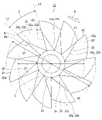
- FIG. 3 is a plan view of the impeller according to this embodiment.
- FIG. 4 is a perspective view showing the impeller according to this embodiment from the bottom side.
- FIG. 5 is a longitudinal sectional view of the impeller and bell mouth according to this embodiment.
- the impeller 23 of the blower device 6 is substantially parallel to the downstream side 19 connected to the bell mouth 7 and is arranged radially.
- a plurality of wing portions 32 protruding from the main plate portion 31 toward the downstream side surface 19 and the bell mouth 7 and arranged in an annular shape; and a hub portion 33 provided at the center of the main plate portion 31. I have.
- the impeller 23 is an integrally molded product made of fiber reinforced plastic (FRP), aluminum alloy, or magnesium metal.
- the impeller 23 is made of fiber-reinforced plastic, for example, and integrally molded by hand lay-up.
- the main plate portion 31 has a flat plate shape with a substantially uniform thickness.
- the main plate portion 31 is an assembly of a plurality of petal portions 35 radially extending from the hub portion 33 in the radial direction of the impeller 23 .
- Each petal portion 35 has a first side portion 35a having a linear edge and a second side portion 35b having a linear edge. Or it extends in a tapered shape.
- the first side portion 35 a of each petal portion 35 is also called the first edge of the main plate portion 31
- the second side portion 35 b of each petal portion 35 is also called the second edge of the main plate portion 31 .
- the first side 35 a of one petal 35 faces the second side 35 b of the other petal 35 .
- the first side portion 35a of one petal portion 35 and the second side portion 35b of the other petal portion 35 face each other with a gap in the circumferential direction of the main plate portion 31 .
- the shapes of all the petals 35 are substantially the same.
- the ends of the plurality of petals 35 located radially inward of the turbofan 8 that is, the root ends of the plurality of petals 35 tightly surround the outer periphery of the hub portion 33 .
- the root end of the first side portion 35 a of one petal portion 35 coincides with the root end of the second side portion 35 b of the other petal portion 35 .
- the ends of the plurality of petals 35 located radially outward of the turbofan 8, that is, the projecting ends of the plurality of petals 35 are connected by a virtual circle. This virtual circle corresponds to the outermost diameter D ⁇ b>1 of the main plate portion 31 .
- a plurality of wing portions 32 and hub portions 33 protrude from the main plate portion 31 in the same direction.
- the hub portion 33 has a truncated cone shape that tapers away from the main plate portion 31 .
- the protrusion height of the plurality of blade portions 32 with respect to the main plate portion 31 is higher than the protrusion height of the hub portion 33 .
- the number of wings 32 that is, the number of wings is a prime number, and is 11 in this embodiment.
- All wings 32 are plates of uniform thickness.
- the plurality of wings 32 are open. That is, the impeller 23 does not have a shroud that connects the projecting ends 32a of the plurality of blades 32. As shown in FIG.
- Each wing portion 32 is connected only to the main plate portion 31 and is not in contact with and is not connected to the hub portion 33 .
- a root end 32 b of each wing portion 32 is an edge of each wing portion 32 that continues to the main plate portion 31 .
- a root end 32b of each wing portion 32 continues to a first side portion 35a of each petal portion 35 .
- Each wing portion 32 protrudes from the first side portion 35 a of each petal portion 35 . Therefore, the root end 32b of each wing portion 32 has the same linear shape as the first side portion 35a of each petal portion 35 and has a linear shape that matches the chord of the blade.
- Each blade portion 32 is inclined in the circumferential direction of the turbofan 8 and in the direction away from the second side portion 35b of each petal portion 35. Further, each blade portion 32 is inclined radially outward of the turbofan 8 from the root end 32b toward the projecting end 32a. Therefore, the outermost diameter D2 drawn by the plurality of blade portions 32 is larger than the outermost diameter D1 of the main plate portion 31 .
- the impeller 23 rotates in a direction R in which the first side portion 35a of each petal portion 35 precedes the second side portion 35b to flow air. That is, the front edge 41 of each blade 32 is positioned on the inner peripheral side of the impeller 23 , and the trailing edge 42 of the blade 32 is positioned on the outer peripheral side of the impeller 23 .
- a first line segment L1 connecting the trailing edge 42 of the first blade portion 32 and the rotation centerline C and the first line segment L1 adjacent to the first blade portion 32 The angle ⁇ between the trailing edge 42 of the second wing portion 32 and the second line segment L2 connecting the rotation center line C is preferably 25 degrees or more. That is, the number of wings 32 is preferably a prime number of 13 or less, and is 11 in this embodiment.
- each wing portion 32 protrudes toward the upstream end 7a of the bell mouth 7 from the first portion 45 arranged close to the downstream side 19 and the downstream end 7b of the bell mouth 7. and a second portion 46 where the second portion 46 is located. That is, the protruding end 32 a of each wing 32 has a convex portion 47 that enters the inside of the bell mouth 7 .
- the convex portion 47 protrudes following the shape of the bell mouth 7 .
- the second portion 46 is the ridgeline of the convex portion 47 .
- the first portion 45 of the wing portion 32 and the downstream side surface 19 are arranged to face each other with an interval of about several millimeters therebetween.
- the distance between the impeller 23 and the bell mouth 7 is preferably as close as possible within the range in which the impeller 23 can rotate smoothly without interfering with the bell mouth 7 .
- each wing portion 32 is thinner than the thickness of the main plate portion 31 .
- Such a thickness relationship is compared to the case where the thickness of each wing portion 32 is the same as the thickness of the main plate portion 31 or the case where the thickness of each wing portion 32 is thicker than the thickness of the main plate portion 31.
- reduce the centrifugal force acting on the wings 32 reduces the deformation of the wing portions 32 and prevents the reduction in the air volume due to the deformation of the wing portions 32 .
- the main plate portion 31, which is thicker than each wing portion 32 reduces deformation of the wing portions 32 due to centrifugal force, and prevents reduction in air volume due to deformation of the wing portions 32.
- FIG. 6 is a perspective view of the wing portion of the impeller according to this embodiment.
- the planar shape of the blade portion 32 of the impeller 23 is close to a quadrangle, for example, a parallelogram.
- the root end 32b has a linear shape that continues to the first side portion 35a of the petal portion 35 .
- a straight line connecting point a and point b in FIG. 6 is root end 32b.
- the protruding end 32a has a non-linear shape and has a protrusion 47 that passes through the protruding end of the trailing edge 42 and protrudes in a direction away from the root end 32b with respect to an imaginary line VL parallel to the root end 32b.
- the projecting end 32a is a line connecting points c, d, and e in FIG.
- a line connecting points a and c in FIG. 6 is the leading edge 41 of the wing 32 , and a line connecting points b and e in FIG.
- the convex portion 47 has a straight edge 48 that continues to the front edge 41 and is parallel to the root end 32 b and parallel to the main plate portion 31 , and a curved edge 49 that connects the straight edge 48 and the rear edge 42 .
- a straight edge 48 is a straight line connecting points c and d in FIG. 6, and a curved edge 49 is a curved line connecting points d and e in FIG.
- the straight edge 48 and part of the curved edge 49 that follows the bellmouth 7 are the second portion 46 of the protruding end 32a, and the remainder of the curved edge 49 is the first portion 45 located adjacent the downstream side 19. is. That is, the remainder of curvilinear edge 49 is substantially parallel to root end 32b. Between the protruding end 32 a and the bell mouth 7 and between the protruding end 32 a and the downstream side surface 19 , there are gaps that do not hinder the rotation of the impeller 23 . This gap is preferably 5 millimeters or less.
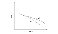
- FIG. 7 is a diagram comparing the characteristics of the impeller according to the present embodiment and the characteristics of the impeller of the comparative example.
- FIG. 7 is a diagram showing the relationship between the static pressure P of the impeller and the flow rate Q of the impeller, which is the so-called PQ characteristic.
- the impeller of the comparative example does not have the protrusions 47 on each of the blades 32, and has projecting ends parallel to the downstream side surface 19 and the main plate portion 31.
- the protruding end of the impeller of the comparative example does not protrude into the bell mouth 7 and is arranged close to the downstream side 19 that is arranged on the same plane and continues to the bell mouth 7 .
- the PQ characteristic of the impeller 23 according to the present embodiment is represented by a curve ⁇ 1
- the PQ characteristic of the impeller of the comparative example is represented by a curve ⁇ 1.
- the impeller 23 according to this embodiment can blow more air than the impeller of the comparative example. Further, the impeller 23 according to the present embodiment can obtain a higher static pressure than the impeller of the comparative example by bringing it close to the bellmouth 7 .
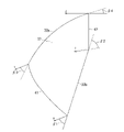
- FIG. 8 is a schematic diagram of the inlet angle and outlet angle of the blade portion of the impeller according to this embodiment.
- the inlet angle and the outlet angle of the blade portion 32 are represented by angles based on the rotation direction of the impeller 23. That is, the inlet angle of the wing portion 32 is the angle between the propelling direction u of the wing portion 32 and the forward direction of the blade arc, and the exit angle of the wing portion 32 is the angle between the propelling direction u of the wing portion 32 and the backward direction of the blade arc. is the angle formed by
- the blade portion 32 of the impeller 23 has an inlet angle ⁇ 1 of the root end 32b, an outlet angle ⁇ 2 of the root end 32b, an inlet angle ⁇ 3 of the projecting end 32a, and an angle ⁇ 3 of the projecting end 32a. It has an exit angle ⁇ 4.
- the exit angle ⁇ 2 of the root end 32b is greater than the entrance angle ⁇ 1 of the root end 32b.
- the entrance angle ⁇ 3 of the protruding end 32a and the exit angle ⁇ 4 of the protruding end 32a may be appropriately set from the respective velocity triangles.
- the protruding end 32 a has a curved shape that protrudes outward in the radial direction of the impeller 23 .
- the airfoil of the wing portion 32 is a three-dimensional shape that smoothly continues from the linear root end 32b to the curved protruding end 32a. Therefore, the airfoil of each airfoil portion 32 is a plate of substantially uniform thickness that is convexly curved radially outwardly of the impeller 23 so that the protruding distance from the chord increases as it approaches the protruding end 32a. Shape.
- FIG. 9 is a diagram comparing the characteristics of the impeller according to the present embodiment and the characteristics of the impeller of the comparative example.
- FIG. 9 is a diagram showing the relationship between the static pressure P of the impeller and the flow rate Q of the impeller, which is the so-called PQ characteristic.
- the outlet angle ⁇ 2 of the root end 32b of the impeller of the comparative example is smaller than the inlet angle ⁇ 1 of the root end 32b.
- a curve ⁇ 2 represents the PQ characteristic of the impeller 23 according to the present embodiment, and a curve ⁇ 2 represents the PQ characteristic of the impeller of the comparative example.
- the impeller 23 according to this embodiment can blow more air than the impeller of the comparative example. Further, the impeller 23 according to the present embodiment can obtain a higher static pressure than the impeller of the comparative example by bringing it close to the bellmouth 7 .
- FIG 10 and 11 are perspective views showing another example of the impeller according to this embodiment from the bottom side.
- the impellers 23A and 23B may include reinforcing members 51A and 51B that connect the second parts 46 of the plurality of blade portions 32.
- the reinforcing members 51A and 51B are not the shrouds of conventional impellers that have a width in the radial direction and have a large dimensional difference between the outer diameter and the inner diameter, but are linear members such as steel wires. is.
- the reinforcing members 51A and 51B connect the second parts 46 of a pair of adjacent wing parts 32 and connect the second parts 46 of all the wing parts 32 .
- All wings 32 may be connected with a single reinforcing member 51A, 51B, or all wings 32 may be connected with a plurality of reinforcing members 51A, 51B that connect two or more but less than the total number of wings 32. It's okay to be
- the reinforcing member 51A may have a simple circular shape and may be fixed so as to make point contact with the second portion 46 of each wing portion 32 (Fig. 10).
- the reinforcing member 51B has a first straight portion 52 along the second portion 46 of each wing portion 32, and a second straight portion 53 bridging between a pair of adjacent wing portions 32. It may be fixed in line contact with the second portion 46 of the portion 32 (FIG. 11).
- the blower device 6 includes the ring-shaped bell mouth 7, the flat downstream side 19 connected to the downstream end 7b of the bell mouth 7, and the downstream side 19 by sucking air from the bell mouth 7. and an impeller 23 for blowing out air in a direction along.
- the impeller 23 includes a main plate portion 31 extending radially and substantially parallel to the downstream side 19 and a plurality of open blade portions 32 .
- the outermost diameter D ⁇ b>2 drawn by the plurality of blade portions 32 is larger than the outermost diameter D ⁇ b>1 of the main plate portion 31 .
- the protruding ends 32a of the plurality of wings 32 protrude toward the upstream end 7a of the bell mouth 7 from the first portion 45 arranged close to the downstream side 19 and the downstream end 7b of the bell mouth 7. and a second portion 46 where the second portion 46 is located. Therefore, the blower device 6 can suppress turbulence in the flow of the air blown out from the impeller 23 and prevent a decrease in blowing efficiency. In addition, the blower 6 draws in air from the bell mouth 7 connected to the flat downstream side 19 and can generate an unturbulent air flow along the flat downstream side 19 .
- the air blower 6 has a second portion 46 projecting toward the upstream end 7a of the bell mouth 7 from the downstream end 7b of the bell mouth 7, that is, the projection 47 of the wing portion 32.
- the air volume can be easily increased compared to a blower without the air blower.
- the impeller 23 does not have a shroud, it can be integrally molded. Therefore, the impeller 23 eliminates factors that cause defects such as poor welding and poor adhesion when the separate shroud is joined to the wing portion. It is possible to reduce the imbalance amount of rotation balance.
- the impeller 23 includes a plurality of blade portions 32 that are connected only to the main plate portion 31 . Therefore, the impeller 23 can be easily made lighter than a conventional impeller having a shroud and a frame, and can eliminate obstacles to the air flow.
- the impeller 23 includes the wing portions 32 having root ends 32b that are continuous with the first side portions 35a of the respective petal portions 35, which are part of the edge of the main plate portion 31. Therefore, the impeller 23 can smoothly blow out the flow of air to which energy is given by the blade portion 32 .
- the impeller 23 has a first side portion 35a of the petal portion 35 and a second side portion 35b of the petal portion 35 facing each other across a gap in the circumferential direction of the main plate portion 31 . Therefore, the impeller 23 can blow out the air energized by the blades 32 through the gaps between the adjacent petals 35 . Such air flow improves the air blowing function of the impeller 23 .
- the gaps between the adjacent petals 35 improve the workability of each step in the hand lay-up method when integrally molding the impeller 23 and facilitate mold release.
- the impeller 23 includes a plurality of blade portions 32 each having a higher protrusion height than the hub portion 33 . Therefore, the impeller 23 can reduce the airflow resistance of the hub portion 33 and easily push out the airflow with the wing portions 32 .
- the exit angle ⁇ 2 of the root end 32b of each blade 32 of the impeller 23 according to the present embodiment is larger than the entrance angle ⁇ 1 of the root end 32b of the blade 32 . Therefore, the amount of air blown by the blower 6 is higher than that of an air blower having an impeller having a root portion in which the outlet angle ⁇ 2 is smaller than the inlet angle ⁇ 1. Also, the blower 6 can more easily provide a higher static pressure than a blower with an impeller whose outlet angle ⁇ 2 is smaller than the inlet angle ⁇ 1.
- the root end 32b of each blade portion 32 of the impeller 23 according to the present embodiment has a linear shape. Therefore, the air blower 6 can easily set the outlet angle ⁇ 2 of the root end 32b of each blade 32 to be larger than the inlet angle ⁇ 1 of the root end 32b of the blade 32 .
- each blade portion 32 of the impeller 23 is thinner than the thickness of the main plate portion 31 . Therefore, the impeller 23 reduces the deformation of the blade portion 32 and prevents the reduction of the air volume due to the deformation of the blade portion 32 .
- the impeller 23 has a prime blade portion 32, and a pair of line segments L1 and L2 connecting the trailing edge 42 and the rotation center line C forms an angle of 25 degrees or more. Adjacent wings 32 are provided. Therefore, the impeller 23 reduces noise called blade pitch noise, reduces the air flow resistance generated between the adjacent blade portions 32 to improve the air volume, and furthermore, the manufacturability when integrally molding the impeller 23 improve.
- the impeller 23 may include a reinforcing member 51 that connects the second portions 46 of the plurality of blade portions 32 . Therefore, even if the impeller 23 does not have a shroud, the weight of the entire impeller 23 is reduced, the influence of the centrifugal force on the blade portion 32 is reduced, the decrease in the air volume is suppressed, and the blade portion 32 is reduced. This prevents collision between the bell mouth 7 and the wings 32 due to deformation.
- blower device 6 According to the blower device 6 according to the present embodiment, air can be efficiently sucked from the bell mouth 7 and blown with high efficiency.
- Hub part 35 Petal portion 35a First side portion 35b Second side portion 41 Front edge 42 Rear edge 45 First portion 46 Second portion 47 Convex portion 48 Linear edge 49... Curved edge, 51A, 51B... Reinforcement member, 52... First straight portion, 53... Second straight portion.
Landscapes
- Engineering & Computer Science (AREA)
- Mechanical Engineering (AREA)
- General Engineering & Computer Science (AREA)
- Structures Of Non-Positive Displacement Pumps (AREA)
Abstract
Description
Claims (6)
- 環状のベルマウスと、
前記ベルマウスの下流側端に連なる平坦な下流側面と、
前記ベルマウスから空気を吸い込んで前記下流側面に沿う方向へ空気を吹き出す羽根車と、を備え、
前記羽根車は、
前記下流側面に実質的に平行し、かつ放射状に広がる主板部と、
前記主板部から前記下流側面および前記ベルマウスへ向かって突出して環状に配列される開放型の複数の翼部と、を備え、
前記複数の翼部が描く最外径は、前記主板部の最外径より大きく、
前記複数の翼部の突出端は、前記下流側面に近接して配置された第一部位と、前記ベルマウスの前記下流側端よりも前記ベルマウスの上流側端へ向かって突出している第二部位と、を有する送風装置。 an annular bellmouth,
a flat downstream side continuous with the downstream end of the bell mouth;
an impeller that draws in air from the bell mouth and blows out the air in a direction along the downstream side;
The impeller is
a main plate portion substantially parallel to the downstream side and extending radially;
a plurality of open wing portions arranged in a ring projecting from the main plate portion toward the downstream side surface and the bell mouth;
The outermost diameter drawn by the plurality of wing portions is larger than the outermost diameter of the main plate portion,
The protruding ends of the plurality of wing portions include a first portion arranged close to the downstream side surface and a second portion protruding toward the upstream end of the bell mouth from the downstream end of the bell mouth. and a blower device. - それぞれの前記翼部の前記主板部に連なる根元端の出口角は、前記根元端の入口角よりも大きい請求項1に記載の送風装置。 2. The blower according to claim 1, wherein the exit angle of the root end of each of the blades connected to the main plate is greater than the entrance angle of the root end.
- それぞれの前記翼部の前記主板部に連なる根元端は、直線形状である請求項1または2に記載の送風装置。 The air blower according to claim 1 or 2, wherein the base end of each of the blades connected to the main plate has a linear shape.
- それぞれの前記翼部の肉厚は、前記主板部の肉厚よりも薄い請求項1から3のいずれか1項に記載の送風装置。 The air blower according to any one of claims 1 to 3, wherein the thickness of each of the blade portions is thinner than the thickness of the main plate portion.
- 前記複数の翼部の数量は、素数であり、
前記羽根車の回転中心線に沿う方向から見て、第一翼部の後縁と前記回転中心線とを結ぶ第一線分と、前記第一翼部に隣り合う第二翼部の後縁と前記回転中心線とを結ぶ第二線分とがなす角度が、25度以上である請求項1から4のいずれか1項に記載の送風装置。 the quantity of the plurality of wings is a prime number;
A first line segment connecting the trailing edge of the first blade portion and the rotation center line, and the trailing edge of the second blade portion adjacent to the first blade portion, when viewed from the direction along the rotation center line of the impeller. 5. The blower device according to claim 1, wherein an angle formed by a second line segment connecting the second line segment and the rotation center line is 25 degrees or more. - 前記複数の翼部の前記第二部位を連結する補強部材を備える請求項1から5のいずれか1項に記載の送風装置。 The blower device according to any one of claims 1 to 5, further comprising a reinforcing member that connects the second portions of the plurality of blade portions.
Priority Applications (3)
| Application Number | Priority Date | Filing Date | Title |
|---|---|---|---|
| CN202180084260.XA CN116601392A (en) | 2021-03-25 | 2021-03-25 | Air supply device |
| PCT/JP2021/012710 WO2022201468A1 (en) | 2021-03-25 | 2021-03-25 | Blower device |
| JP2023508350A JP7458552B2 (en) | 2021-03-25 | 2021-03-25 | Air blower |
Applications Claiming Priority (1)
| Application Number | Priority Date | Filing Date | Title |
|---|---|---|---|
| PCT/JP2021/012710 WO2022201468A1 (en) | 2021-03-25 | 2021-03-25 | Blower device |
Publications (1)
| Publication Number | Publication Date |
|---|---|
| WO2022201468A1 true WO2022201468A1 (en) | 2022-09-29 |
Family
ID=83396628
Family Applications (1)
| Application Number | Title | Priority Date | Filing Date |
|---|---|---|---|
| PCT/JP2021/012710 WO2022201468A1 (en) | 2021-03-25 | 2021-03-25 | Blower device |
Country Status (3)
| Country | Link |
|---|---|
| JP (1) | JP7458552B2 (en) |
| CN (1) | CN116601392A (en) |
| WO (1) | WO2022201468A1 (en) |
Citations (3)
| Publication number | Priority date | Publication date | Assignee | Title |
|---|---|---|---|---|
| JPS5389607U (en) * | 1976-12-24 | 1978-07-22 | ||
| JP2003180051A (en) * | 2001-12-10 | 2003-06-27 | Fuji Electric Co Ltd | Moving blade of totally-enclosed fan-cooled rotating electric machine |
| JP2007292026A (en) * | 2006-04-27 | 2007-11-08 | Toshiba Home Technology Corp | Fan motor |
-
2021
- 2021-03-25 JP JP2023508350A patent/JP7458552B2/en active Active
- 2021-03-25 WO PCT/JP2021/012710 patent/WO2022201468A1/en active Application Filing
- 2021-03-25 CN CN202180084260.XA patent/CN116601392A/en active Pending
Patent Citations (3)
| Publication number | Priority date | Publication date | Assignee | Title |
|---|---|---|---|---|
| JPS5389607U (en) * | 1976-12-24 | 1978-07-22 | ||
| JP2003180051A (en) * | 2001-12-10 | 2003-06-27 | Fuji Electric Co Ltd | Moving blade of totally-enclosed fan-cooled rotating electric machine |
| JP2007292026A (en) * | 2006-04-27 | 2007-11-08 | Toshiba Home Technology Corp | Fan motor |
Also Published As
| Publication number | Publication date |
|---|---|
| JPWO2022201468A1 (en) | 2022-09-29 |
| JP7458552B2 (en) | 2024-03-29 |
| CN116601392A (en) | 2023-08-15 |
Similar Documents
| Publication | Publication Date | Title |
|---|---|---|
| US10890194B2 (en) | Air-sending device and air-conditioning apparatus using the same | |
| EP3043077B1 (en) | Propeller fan, air-blowing device, and outdoor unit | |
| JP6945739B2 (en) | Multi-blade blower and air conditioner | |
| US11976872B2 (en) | Axial flow fan, air-sending device, and refrigeration cycle apparatus | |
| JP6611676B2 (en) | Outdoor unit for blower and refrigeration cycle equipment | |
| KR20170006833A (en) | Blower and air conditioner having the same | |
| WO2022201468A1 (en) | Blower device | |
| US11674520B2 (en) | Centrifugal fan and air-conditioning apparatus | |
| CN114174726B (en) | Indoor unit and impeller of refrigeration cycle device | |
| JP2701604B2 (en) | Air conditioner | |
| WO2023074578A1 (en) | Impeller | |
| JP6745902B2 (en) | Blower, outdoor unit and refrigeration cycle device | |
| EP3916238A1 (en) | Fan blower, indoor unit, and air conditioner | |
| CN109891101B (en) | Propeller fan, outdoor unit, and refrigeration cycle device | |
| WO2023084652A1 (en) | Cross-flow fan, blowing device, and refrigeration cycle device | |
| JP6430032B2 (en) | Centrifugal fan, air conditioner and refrigeration cycle apparatus | |
| EP4098885A1 (en) | Centrifugal blower and air conditioner provided with same | |
| JP7245339B2 (en) | Propeller fan impellers, air blowers, and air conditioner outdoor units | |
| WO2021172360A1 (en) | Centrifugal compressor | |
| JP6625213B2 (en) | Multi-blade fan and air conditioner | |
| JP2023044874A (en) | Ceiling-embedded type air conditioner | |
| CN117222815A (en) | Blower, air conditioner, and refrigeration cycle device |
Legal Events
| Date | Code | Title | Description |
|---|---|---|---|
| 121 | Ep: the epo has been informed by wipo that ep was designated in this application |
Ref document number: 21933073 Country of ref document: EP Kind code of ref document: A1 |
|
| ENP | Entry into the national phase |
Ref document number: 2023508350 Country of ref document: JP Kind code of ref document: A |
|
| WWE | Wipo information: entry into national phase |
Ref document number: 202180084260.X Country of ref document: CN |
|
| NENP | Non-entry into the national phase |
Ref country code: DE |
|
| 122 | Ep: pct application non-entry in european phase |
Ref document number: 21933073 Country of ref document: EP Kind code of ref document: A1 |