WO2022201422A1 - 画像処理装置、プログラム及び画像処理方法 - Google Patents
画像処理装置、プログラム及び画像処理方法 Download PDFInfo
- Publication number
- WO2022201422A1 WO2022201422A1 PCT/JP2021/012515 JP2021012515W WO2022201422A1 WO 2022201422 A1 WO2022201422 A1 WO 2022201422A1 JP 2021012515 W JP2021012515 W JP 2021012515W WO 2022201422 A1 WO2022201422 A1 WO 2022201422A1
- Authority
- WO
- WIPO (PCT)
- Prior art keywords
- data
- image
- expected
- background
- detected
- Prior art date
- Legal status (The legal status is an assumption and is not a legal conclusion. Google has not performed a legal analysis and makes no representation as to the accuracy of the status listed.)
- Ceased
Links
Images



Classifications
-
- G—PHYSICS
- G06—COMPUTING OR CALCULATING; COUNTING
- G06T—IMAGE DATA PROCESSING OR GENERATION, IN GENERAL
- G06T7/00—Image analysis
- G06T7/70—Determining position or orientation of objects or cameras
-
- G—PHYSICS
- G06—COMPUTING OR CALCULATING; COUNTING
- G06T—IMAGE DATA PROCESSING OR GENERATION, IN GENERAL
- G06T7/00—Image analysis
- G06T7/0002—Inspection of images, e.g. flaw detection
- G06T7/0004—Industrial image inspection
-
- G—PHYSICS
- G06—COMPUTING OR CALCULATING; COUNTING
- G06T—IMAGE DATA PROCESSING OR GENERATION, IN GENERAL
- G06T15/00—Three-dimensional [3D] image rendering
-
- G—PHYSICS
- G06—COMPUTING OR CALCULATING; COUNTING
- G06T—IMAGE DATA PROCESSING OR GENERATION, IN GENERAL
- G06T7/00—Image analysis
- G06T7/50—Depth or shape recovery
-
- G—PHYSICS
- G06—COMPUTING OR CALCULATING; COUNTING
- G06T—IMAGE DATA PROCESSING OR GENERATION, IN GENERAL
- G06T7/00—Image analysis
- G06T7/70—Determining position or orientation of objects or cameras
- G06T7/73—Determining position or orientation of objects or cameras using feature-based methods
-
- G—PHYSICS
- G06—COMPUTING OR CALCULATING; COUNTING
- G06V—IMAGE OR VIDEO RECOGNITION OR UNDERSTANDING
- G06V10/00—Arrangements for image or video recognition or understanding
- G06V10/20—Image preprocessing
- G06V10/28—Quantising the image, e.g. histogram thresholding for discrimination between background and foreground patterns
-
- G—PHYSICS
- G06—COMPUTING OR CALCULATING; COUNTING
- G06V—IMAGE OR VIDEO RECOGNITION OR UNDERSTANDING
- G06V10/00—Arrangements for image or video recognition or understanding
- G06V10/70—Arrangements for image or video recognition or understanding using pattern recognition or machine learning
- G06V10/74—Image or video pattern matching; Proximity measures in feature spaces
- G06V10/761—Proximity, similarity or dissimilarity measures
-
- G—PHYSICS
- G06—COMPUTING OR CALCULATING; COUNTING
- G06T—IMAGE DATA PROCESSING OR GENERATION, IN GENERAL
- G06T2207/00—Indexing scheme for image analysis or image enhancement
- G06T2207/10—Image acquisition modality
- G06T2207/10024—Color image
-
- G—PHYSICS
- G06—COMPUTING OR CALCULATING; COUNTING
- G06T—IMAGE DATA PROCESSING OR GENERATION, IN GENERAL
- G06T2207/00—Indexing scheme for image analysis or image enhancement
- G06T2207/20—Special algorithmic details
- G06T2207/20092—Interactive image processing based on input by user
- G06T2207/20101—Interactive definition of point of interest, landmark or seed
-
- G—PHYSICS
- G06—COMPUTING OR CALCULATING; COUNTING
- G06T—IMAGE DATA PROCESSING OR GENERATION, IN GENERAL
- G06T2207/00—Indexing scheme for image analysis or image enhancement
- G06T2207/30—Subject of image; Context of image processing
- G06T2207/30108—Industrial image inspection
- G06T2207/30164—Workpiece; Machine component
-
- G—PHYSICS
- G06—COMPUTING OR CALCULATING; COUNTING
- G06V—IMAGE OR VIDEO RECOGNITION OR UNDERSTANDING
- G06V2201/00—Indexing scheme relating to image or video recognition or understanding
- G06V2201/07—Target detection
Definitions
- the present disclosure relates to an image processing device, a program, and an image processing method.
- a typical laser processing machine is equipped with a laser oscillator that oscillates a laser, an optical path through which the laser passes, a processing head that condenses and emits the laser, and a table on which the plate material is placed.
- a laser oscillator that oscillates a laser
- an optical path through which the laser passes a processing head that condenses and emits the laser
- a table on which the plate material is placed a plate to be processed is placed on the table of the laser processing machine, the processing head is moved according to the coordinate system of the laser processing machine, and laser light is emitted to perform processing.
- the plate material is placed at the expected position and inclination with respect to the coordinate system of the laser processing machine, it is possible to pick up the part as per the nesting, but in reality, the position or inclination of the plate material is shifted. May be placed on a table.
- a plate material is placed on a detachable table in advance and automatically carried into the laser processing machine together with the table. In this case, the position or tilt is likely to shift due to vibrations during transportation.
- an image processing apparatus for laser processing which is described in Patent Document 1, performs an operation using a captured image of a measurement object, position measurement data, and three-dimensional reference data. , to calculate accurate position information of the object to be measured.
- the imaging unit is arranged at a position facing the illumination unit with the object to be measured interposed therebetween, so that the illumination light from the illumination unit passes through the hole or the outer surface of the object to be measured. .
- This image processing apparatus acquires an image in which the transmitted light is captured by the imaging unit and the outline of the hole or the outer surface of the object to be measured is emphasized. As a result, it is possible to accurately determine the position and inclination of the object to be measured, such as a plate, without being affected by lighting conditions such as illumination light or outside light, or shooting conditions such as the state of cutting oil applied to the plate. .
- the detection rate of the measurement object can be improved, but the scale of the device increases and the cost also increases.
- an object of one or more aspects of the present disclosure is to make it possible to determine whether or not an object has been accurately detected with a simple configuration.
- An image processing apparatus processes captured image data representing a captured image that is an image including an object to be detected and a background of the object, thereby obtaining a processed image that is an image in which the object is detected. and a virtual image in which the object is placed at the position on the background based on the object data indicating the position of the object and the background data indicating the background
- a detection result for determining whether or not the object is correctly detected in the processed image data by comparing the processed image data and the expected data with an expected data generation unit that generates expected data representing the expected image and a determination unit.
- a program causes a computer to process captured image data representing a captured image that is an image including an object to be detected and a background of the object, thereby processing an image in which the object is detected.
- an object detection unit for generating processed image data representing an image; placing the object represented by the attribute at the position on the background based on object data representing the position of the object and background data representing the background; and an expected data generation unit for generating expected data indicating an expected image, which is a virtual image that has been processed, and by comparing the processed image data and the expected data, whether or not the object has been correctly detected in the processed image data. It is characterized by functioning as a detection result determination unit that determines whether or not.
- An image processing method is a processed image that is an image in which the object is detected by processing captured image data representing a captured image that is an image that includes an object to be detected and a background of the object. and based on the object data indicating the position of the object and the background data indicating the background, an expected image that is a virtual image in which the object is arranged at the position on the background is generated, and the processed image data and the expected data are compared to determine whether or not the object is correctly detected in the processed image data.
- FIG. 1 is a block diagram schematically showing the configuration of a laser processing machine according to Embodiments 1 and 2; FIG. It is a schematic perspective view for demonstrating a laser oscillator and a processing head.
- 1 is a block diagram schematically showing the configuration of an image processing apparatus according to Embodiment 1;
- FIG. (A) to (C) are schematic diagrams for explaining the operation of generating expected data.
- (A) to (C) are schematic diagrams for explaining complementary processing in a detection result determination unit.
- (A) to (C) are schematic diagrams for explaining correction processing in a detection result determination unit.
- FIG. 1 is a block diagram schematically showing the configuration of a laser processing machine 100 according to Embodiment 1.
- the laser processing machine 100 includes a laser oscillator 101 , a processing head 102 , an imaging device 103 , an input device 104 , a display device 105 and a control device 106 .
- a laser oscillator 101 is a device that oscillates a laser.
- the processing head 102 is a device that condenses and emits laser light.
- FIG. 2 is a schematic perspective view for explaining the laser oscillator 101 and the processing head 102.
- the laser oscillator 101 and the processing head 102 are connected by an optical path 107 through which the laser passes.
- a plate material 109 to be processed is placed on the table 108, the processing head 102 is moved according to the coordinate system of the laser processing machine 100, and the laser oscillated by the laser oscillator 101 is emitted from the processing head 102 to perform processing. is done.
- the imaging device 103 is a device for capturing an image of an object and its background.
- the imaging device 103 is a camera such as a CCD (Charge Coupled Device).
- the input device 104 is a device that receives input of various instructions from the user.
- the display device 105 is a device that displays various screen images.
- the display device 105 may be a programmable display or the like that displays operation results or device status.
- the input device 104 and the display device 105 may be configured as one device using a touch panel, for example.
- the control device 106 is a computer that controls processing in the laser processing machine 100 .
- the control device 106 controls operations of the laser oscillator 101 , processing head 102 , imaging device 103 , input device 104 and display device 105 .
- the control device 106 includes a ROM (Read Only Memory) 106a, a HDD (Hard Disk Drive) 106b, a RAM (Random Access Memory) 106c, and a CPU (Central Processing Unit) 106d.
- ROM Read Only Memory
- HDD Hard Disk Drive
- RAM Random Access Memory
- CPU Central Processing Unit
- the ROM 106a is a non-volatile memory that stores data and programs.
- the HDD 106b is a storage device that stores data and programs.
- the HDD 106b is composed of a magnetic memory or the like, and stores, for example, software, which is a group of programs required for various processes by the CPU 106d. It should be noted that the programs constituting various processing software by the CPU 106d may be incorporated in the computer in advance as dedicated hardware, or may be incorporated in the ROM 106a or the HDD 106b in advance.
- the RAM 106c is a volatile memory that provides a work area for the CPU 106d.
- the RAM 106c temporarily stores intermediate results of calculations performed by the CPU 106d.
- the CPU 106d can write to or read from the RAM 106c at high speed.
- the CPU 106d reads a program stored in the ROM 106a or the HDD 106b into the RAM 106c and executes the program to control processing in the laser processing machine 100.
- the CPU 106d processes instructions of various programs.
- the CPU 106d also temporarily stores data necessary for each process in the RAM 106c or the HDD 106b.
- control device 106 shown in FIG. 1 is realized by a so-called computer, but the present embodiment is not limited to such an example.
- the control device 106 may be implemented by a processing circuit such as a system LSI.
- controller 106 may be configured with processing circuitry.
- the image processing apparatus according to the first embodiment is realized by the control device 106 as described above.
- the control device 106 is included in the laser processing machine 100, but the control device 106 may be a separate device from the laser processing machine 100.
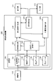
- FIG. 3 is a block diagram schematically showing the configuration of the image processing device 120 according to Embodiment 1.
- the image processing device 120 includes a storage unit 130 , an object detection unit 121 , an expected data generation unit 122 , a detection result determination unit 123 , a display operation unit 124 and a position/tilt calculation unit 125 .
- the image processing device 120 is connected to the imaging unit 110 , the display unit 111 and the input unit 112 .
- the imaging unit 110 is a functional block realized by the imaging device 103 shown in FIG. 1, acquires an image of an object and background, and generates captured image data representing the image.
- the captured image data indicates a captured image that is an image including an object to be detected and the background of the object.
- a display unit 111 is a functional block realized by the display device 105 shown in FIG. 1, and displays various screen images.
- the input unit 112 is a functional block realized by the input device 104 shown in FIG. 1, and receives input of various instructions.
- the storage unit 130 stores data necessary for processing in the image processing device 120 .
- the storage unit 130 stores captured image data 131 , object data 132 , background data 133 and calculation data 134 .
- the captured image data 131 is image data representing an image captured by the imaging unit 110 .
- the object data 132 is data indicating attributes and positions of objects to be detected.
- the attribute is, for example, the name of the physical property, which is the name of the object, the dimensions of the object, or the color of the object.
- the position is, for example, placement coordinates, which are the coordinates of the position where the object is placed.
- the object to be detected is a plate and has a rectangular shape. In other words, it is assumed that the type of object shape is predetermined.
- the attribute of the object data 132 may include the shape type of the object.
- the actual shape of the object here, rectangular shape
- the dimension included in the attribute is information that can specify the shape of the object, and this information may include the attribute of the shape of the object.
- the object data 132 may be data representing numerical values or text representing the dimensions or color of the object, or may be data obtained in advance from digital design data (for example, CAD data, etc.) of the object to be detected. .
- the object data 132 may be registered in advance by the user in a DB (Data Base) or the like and downloaded from the DB, or may be imported from software or the like for creating a nesting program.
- DB Data Base
- the background data 133 is data indicating a background on which the object indicated by the object data is virtually arranged.
- the background data 133 may be image data obtained by photographing the table 108 of the laser processing machine 100 without arranging the object to be detected by the imaging unit 110 .
- the background data 133 may be image data digitally created by simulating the table 108 from information such as the size or color of the table 108 of the laser processing machine 100, or may simply be an area so that the positional relationship of objects can be understood. It may be image data indicated by a rectangle.
- the background data 133 may be text data indicating the size and position of the background area.
- text data for example, color, X coordinate, Y coordinate, width and height information are stored as numeric text information, and when generating the expected data, image data in SVG (Scalable Vector Graphics) format.
- SVG Scalable Vector Graphics
- Background data can be generated by specifying it. ⁇ ?
- the calculation data 134 is data indicating the result calculated by the position/tilt calculation unit 125 .
- the calculation data 134 may be data indicating the position where the object to be detected is arranged and the deviation of the inclination.
- the object detection unit 121 detects an object placed on the table 108 from the captured image, which is the image represented by the captured image data 131 .
- the object detection unit 121 may detect an object by known image processing, and the image processing is not particularly limited. In other words, the object detection unit 121 processes captured image data representing a captured image that is an image that includes an object to be detected and a background of the object, thereby performing processing that represents a processed image that is an image in which the object is detected. Generate image data. The processed image data is given to the detection result determination unit 123 .
- Expected data generator 122 generates expected data based on object data 132 and background data 133 .
- the expected data generation unit 122 generates expected data representing a virtual image when an object having the attribute indicated by the object data 132 is arranged at the position indicated by the object data 132 in the background indicated by the background data 133. Generate.
- An image represented by expected data is also called an expected image.
- FIGS. 4A to 4C are schematic diagrams for explaining the operation of generating expected data.
- object data indicating the size, color, and location coordinates of the object
- background data indicating a background of a single color.
- expected data representing an expected image, which is an image in which an object is arranged on a background of a single color, is generated. Note that in FIG. 4A, arrangement coordinates are specified as the position of the object.
- the image represented by the expected data is almost the same image data as the actual captured image, it can be used as data to complement the shape of the object to be detected when the object cannot be detected correctly from the captured image. .
- the detection result determination unit 123 compares the processed image data from the object detection unit 121 and the expected data from the expected data generation unit 122 to determine whether the object has been correctly detected in the processed image data. For example, when the number of objects indicated by the expected data matches the number of objects that can be specified from the processed image data from the object detection unit 121, the detection result determination unit 123 It is determined that the detection unit 121 can correctly detect the object.
- the detection result determination unit 123 refers to the expected data to determine the following in the processed image data: Complement the object from a part of the object.
- FIG. 5A to 5C are schematic diagrams for explaining the complementing process in the detection result determination unit 123.
- FIG. 5A When the object detection unit 121 detects a part of the object as shown in FIG. 5A, the detection result determination unit 123 determines the expected data as shown in FIG. An image of the object located at the corresponding position can be used to interpolate the object, as shown in FIG. 5(C).
- the detection result determination unit 123 uses the detected part as a template image and performs template matching on the expected image indicated by the expected data, so that the detected part is the part of any object. can determine whether Note that when the part matches a plurality of objects, the detection result determination unit 123 determines which object the part is a part of based on the positional relationship with other detected objects. Just do it.
- the detection result determination unit 123 corrects the shape of the object detected by the object detection unit 121 using the expected data. For example, when the shape of the object detected in the processed image data is different from the shape of the article indicated by the expected data, the detection result determination unit 123 refers to the expected data to determine the shape of the object detected in the processed image data. modify the shape of the object.
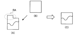
- FIG. 6A to 6C are schematic diagrams for explaining correction processing in the detection result determination unit 123.
- FIG. 6A for example, when detecting a black rectangular plate, the object may be detected as being assimilated with the black background.
- an area RA surrounded by a dashed line is a portion where the shape of the object is not correctly detected because it is assimilated with the background. Even in such a case, using the image of the object arranged at the corresponding position in the expected data as shown in FIG. You can modify the shape of the object.
- the display operation unit 124 receives an operation input from the user to specify the position in the processed image of the object indicated by the expected data, Add an image of the object represented by the expected data. For example, when the object detection unit 121 cannot correctly detect the object and the part of the object is not detected, the display operation unit 124 displays the captured image indicated by the captured image data 131 on the display unit 111. , and an expected image indicated by the expected data are displayed, and the input unit 112 displays the correspondence between one or more objects included in the expected image and the positions of the one or more objects in the captured image. Accept input.
- the display operation unit 124 instructs the user to align one or more object images included in the expected image with one or more corresponding positions in the captured image by an operation such as drag-and-drop. get Then, the display operation unit 124 gives the alignment result to the detection result determination unit 123 . Thereby, the detection result determination unit 123 can add the image of the object included in the expected image to the image of the detection result by the object detection unit 121 .
- the detection result determination unit 123 indicates the target image, which is an image processed by complementing, correcting, or adding the image indicated by the processed image data from the object detection unit 121.
- Target image data is generated, and the target image data is provided to the position/tilt calculator 125 .
- the detection result determination unit 123 uses the processed image data provided from the object detection unit 121 as target image data. It is given to the calculator 125 .
- the position/tilt calculation unit 125 compares the object specified via the processed image data with the object indicated by the expected data, thereby comparing the object specified via the processed image data with respect to the object indicated by the expected data. , and the deviation of the position and inclination of . Specifically, the position/tilt calculation unit 125 compares the target image data from the detection result determination unit 123 with the expected data, and determines whether the object included in the target image data is included in the expected data. Compute position and tilt deviations for the object. Then, the position/tilt calculator 125 generates calculation data 134 indicating the calculated shift, and causes the storage unit 130 to store the calculation data 134 .
- FIG. 7 is a flow chart showing the operation of the image processing device 120 according to the first embodiment.
- the expected data generating unit 122 reads the object data 132 and the background data 133 stored in the storage unit 130, and generates expected data from the object data 132 and the background data 133 (S10).
- the generated expected data is given to the detection result determination unit 123 and the position/tilt calculation unit 125 .
- the generated expected data may be stored in the storage unit 130, referred to by the detection result determination unit 123 and the position/tilt calculation unit 125, and used for the processing of each unit.
- the detection result determination unit 123 reads captured image data 131 generated by capturing images of the object to be detected and the background by the imaging unit 110 from the storage unit 130 (S11).
- the object detection unit 121 performs object detection by performing image processing on the captured image indicated by the captured image data 131 (S12).
- Processed image data representing a processed image which is an image obtained by subjecting the captured image to image processing, is supplied to the detection result determination unit 123 .
- the detection result determination unit 123 compares the expected data and the processed image data, and determines whether or not the object has been correctly detected (S13).
- the detection result determination unit 123 determines that the objects have been correctly detected. If the object is correctly detected (Yes in S13), the process proceeds to step S17, and if the object is not correctly detected (No in S13), the process proceeds to step S14.
- step S14 the detection result determination unit 123 determines whether a part of the article indicated by the expected data is detected in the processed image data (S14). For example, the detection result determination unit 123 determines whether or not the corresponding article is detected in the processed image data within a predetermined range from the position where each article indicated by the expected data is arranged. do. Then, the detection result determination unit 123 identifies one article for which the corresponding article is not detected in the processed image data among the articles indicated by the expected data. Furthermore, the detection result determination unit 123 determines whether or not a part of the specified item is detected at a predetermined position from the position where the specified item is arranged.
- the detection result determination unit 123 detects, in the processed image data, a contour that overlaps the contour of the specified one item at a predetermined position from the position where the specified one item is arranged. determine whether or not When such a contour is detected, the detection result determination unit 123 determines that part of the article indicated by the expected data has been detected in the processed image data. Then, if a part of the article indicated by the expected data is detected in the processed image data (Yes in S14), the process proceeds to step S15, in which the expected data is detected in the processed image data. If a part of the article that is present has not been detected (No in S14), the process proceeds to step S16.
- step S15 the detection result determination unit 123 complements the part of the article detected in the processed image data using the article indicated by the expected data. For example, the detection result determination unit 123 overlaps the image of the article so that the corresponding portion of the article indicated by the expected data overlaps the part detected in the processed image data. Then, returning to the processing step S13, the detection result determination unit 123 determines whether or not the parts complemented in the step S15 are included in the parts detected from the processed image data, and the parts are correctly detected.
- step S16 the detection result determination unit 123 instructs the display operation unit 124 to accept an input from the user regarding the correspondence between the part indicated by the expected data and the part indicated by the processed image data.
- the detection result determination unit 123 compares the shape of the part indicated by the processed image data with the shape of the corresponding part indicated by the expected data, so that the shape of the part indicated by the processed image data is, for example, , the shape of the corresponding part indicated by the expected data is used for correction (S17).
- the position/tilt calculation unit 125 uses the processed image data, or the processed image data complemented, corrected, or added by the detection result determination unit 123 or the display operation unit 124 as target image data. , and the deviation of the position and inclination from the corresponding article indicated by the expected data is calculated (S18).
- the position/tilt calculation unit 125 generates calculation data 134 indicating the calculated deviation, and stores the calculation data 134 in the storage unit 130 (S19).
- the calculated data 134 stored in this manner is referred to by a program that controls the machining path by moving the machining head, and machining is performed by correcting the machining path according to the calculated data.
- Embodiment 2 describes an example in which expected data is referred to in image processing used in object detection.
- a laser processing machine 200 according to the second embodiment includes a laser oscillator 101, a processing head 102, an imaging device 103, an input It comprises a device 104 , a display device 105 and a control device 106 .
- the image processing apparatus realized by the control device 106 is different from the image processing apparatus according to the first embodiment.
- FIG. 8 is a block diagram schematically showing the configuration of an image processing device 220 according to Embodiment 2.
- the image processing device 220 includes a storage unit 130 , an object detection unit 221 , an expected data generation unit 122 , a detection result determination unit 123 , a display operation unit 124 and a position/tilt calculation unit 125 .
- the storage unit 130, the expected data generation unit 122, the detection result determination unit 123, the display operation unit 124, and the position inclination calculation unit 125 of the image processing device 220 according to the second embodiment are the same as those of the image processing device 120 according to the first embodiment. It is the same as the storage unit 130 , the expected data generation unit 122 , the detection result determination unit 123 , the display operation unit 124 and the position/tilt calculation unit 125 .
- the expected data generator 122 also provides the generated expected data to the object detector 221 .
- the generated expected data may be stored in the storage unit 130, referenced by the object detection unit 221, and used for processing.
- the object detection unit 221 detects an object placed on the table 108 from the captured image, which is the image represented by the captured image data 131 .
- the object detection unit 221 in Embodiment 2 refers to the expected data, performs preprocessing on the captured image data using the adaptive binarization filter, and then detects an object from the background.
- the threshold is not fixed, and the average value of the pixel values of the pixel of interest and the pixels surrounding the pixel of interest is used as the threshold, so a different threshold can be set for each pixel. . Therefore, by using the adaptive binarization filter, it is possible to process as expected even in a region where the color changes depending on the lighting environment.
- a local region of arbitrary size is set in the entire image, a threshold value is calculated in the region, and each pixel is binarized. By scanning the local area over the entire image area, binarization of the entire image pixels is performed "with a threshold value that matches each area.”
- a general adaptive binarization filter the user determines the size of the local region, and binarization is performed by the following processes 1 to 3.
- 1 Perform the following 2 and 3 processes for all pixels.
- the average value, median value, or (maximum value+minimum value)/2 of the pixel values of the pixels in the local region is usually used as the threshold value.
- Binarization is performed depending on whether the pixel value of the target pixel is larger or smaller than the threshold obtained in 2 above.
- the size of the local area is made relatively large so that the background and the foreground can be distinguished.
- the object detection unit 121 refers to the expected data to reduce the size of the local region as the degree of similarity between the background color and the object color is lower. can be done.
- the degree of color similarity may be specified by a known method. For example, it may be determined that the smaller the color difference, the higher the degree of similarity.
- the object detection unit 121 can automatically determine an area near the edge of the object indicated by the expected data as a local area.
- the object detection unit 121 can define a local area such that pixels in a predetermined area including pixels that are edges of the object indicated by the expected data are pixels of interest.
- the object detection unit 121 can perform processing using the adaptive binarization filter only on a predetermined region that is part of the captured image and includes the edge of the object indicated by the expected data. can.
- the unused pixels can be treated as background or object interior.
- the object detection unit 121 detects only pixels in a predetermined region including pixels where a board as an object indicated by the expected data is arranged, instead of all pixels of the captured image indicated by the captured image data. can also be used for binarization. In other words, the object detection unit 121 can perform processing using the adaptive binarization filter only on a predetermined region that is part of the captured image and contains the object indicated by the expected data. In this case, the unused pixels can be treated as background.
- the adaptive binarization filter cannot obtain a clear processing result if the area where the color does not change is large. Can be excluded from processing.
- an example of a binarization filter is shown as image processing, but the image processing method to which the present invention is applied is not specified.
- Embodiment 1 or 2 it is possible to determine whether the object has been correctly detected by comparing the result of object detection from the captured image with the expected data created in advance. Thereby, when detection is not correctly performed, the expected data can be used to complement or add to the detection result. Also, the expected data can be used to modify the shape of the object even if it is detected correctly.
- the expected position or edge of the object to be detected with respect to the background data can be grasped in advance. Therefore, by detecting an object by image processing with reference to expected data as in Embodiment 2, image processing is performed only on a limited area such as the vicinity of the object to be detected. can be speeded up, and the accuracy of object detection can be improved. As a result, it is possible to provide a system capable of increasing the detection accuracy of an object without having a three-dimensional measurement unit or an illumination unit, and calculating the position and inclination of the object with a low-cost configuration.
- the image processing apparatuses 120 and 220 measure the position of an object by image processing, and therefore have the advantage of being able to detect the position and inclination of an object in a shorter period of time than conventional apparatuses.
- the prior art document described in Background Art includes an illumination unit and a position measurement unit in order to accurately detect a measurement object, but the scale of the apparatus is large and the cost is also high.
- the image processing apparatuses 120 and 220 according to Embodiments 1 and 2 do not require an illumination unit and a position measurement unit. , the misrecognition rate of object position information can be reduced.
Landscapes
- Engineering & Computer Science (AREA)
- Theoretical Computer Science (AREA)
- Physics & Mathematics (AREA)
- General Physics & Mathematics (AREA)
- Computer Vision & Pattern Recognition (AREA)
- Multimedia (AREA)
- Computing Systems (AREA)
- Artificial Intelligence (AREA)
- Health & Medical Sciences (AREA)
- Databases & Information Systems (AREA)
- Evolutionary Computation (AREA)
- General Health & Medical Sciences (AREA)
- Medical Informatics (AREA)
- Software Systems (AREA)
- Computer Graphics (AREA)
- Quality & Reliability (AREA)
- Image Analysis (AREA)
- Image Processing (AREA)
Abstract
Description
図1は、実施の形態1におけるレーザー加工機100の構成を概略的に示すブロック図である。
レーザー加工機100は、レーザー発振器101と、加工ヘッド102と、撮像装置103と、入力装置104と、表示装置105と、制御装置106とを備える。
加工ヘッド102は、レーザーを集光して射出する装置である。
図2に示されているように、レーザー発振器101と、加工ヘッド102とは、レーザーが通る光路107で接続されている。レーザー加工時には、テーブル108上に加工対象の板材109が配置され、レーザー加工機100が持つ座標系に従って加工ヘッド102が移動され、レーザー発振器101で発振されたレーザーを加工ヘッド102から射出して加工が行われる。
表示装置105は、各種画面画像を表示する装置である。例えば、表示装置105は、操作結果又は装置の状態を表示するプログラマブル表示器等であってもよい。
なお、入力装置104及び表示装置105は、例えば、タッチパネルにより一つの装置で構成されていてもよい。
HDD106bは、データ及びプログラムを格納する記憶装置である。なお、HDD106bは、磁気メモリ等で構成され、例えば、CPU106dによる各種の処理に必要なプログラム群であるソフトウェアを格納する。なお、CPU106dによる各種の処理ソフトウェアを構成するプログラムは、予めコンピュータに専用のハードウェアで組み込まれてもよく、ROM106a又はHDD106bに予め組み込まれていてもよい。
CPU106dは、ROM106a又はHDD106bに記憶されているプログラムをRAM106cに読み出して、そのプログラムを実行することで、レーザー加工機100での処理を制御する。例えば、CPU106dは、各種プログラムの命令を処理する。また、CPU106dは、各処理に必要なデータをRAM106c又はHDD106bに一時記憶する。
言い換えると、制御装置106は、処理回路網により構成することができる。
ここでは、以上のような制御装置106により、実施の形態1に係る画像処理装置が実現される。
なお、図1に示されている例では、制御装置106がレーザー加工機100に含まれているが、制御装置106は、レーザー加工機100とは別の装置であってもよい。
画像処理装置120は、記憶部130と、物体検出部121と、期待データ生成部122と、検出結果判定部123と、表示操作部124と、位置傾き算出部125とを備える。
撮像部110は、図1に示されている撮像装置103により実現される機能ブロックであり、物体及び背景の画像を取得して、その画像を示す撮像画像データを生成する。撮像画像データは、検出対象となる物体及びその物体の背景を含む画像である撮像画像を示す。
表示部111は、図1に示されている表示装置105により実現される機能ブロックであり、各種画面画像を表示する。
入力部112は、図1に示されている入力装置104により実現される機能ブロックであり、各種指示の入力を受け付ける。
例えば、記憶部130は、撮像画像データ131と、物体データ132と、背景データ133と、算出データ134とを記憶する。
撮像画像データ131は、撮像部110で撮像された画像を示す画像データである。
物体データ132は、検出対象の物体の属性及び位置を示すデータである。ここで、属性は、例えば、その物体の名称である物性名称、その物体の寸法、又は、その物体の色等である。位置は、例えば、その物体を配置する位置としての座標である配置座標である。ここでは、検出対象となる物体は、板材であり、矩形の形状を有するものとする。言い換えると、物体の形状の種別が予め定められているものとする。なお、物体データ132の属性に物体の形状の種別が含まれていてもよい。なお、属性に含まれている寸法により、物体の実際の形状(ここでは、矩形の形状)が特定される。言い換えると、属性に含まれている寸法は、物体の形状を特定することのできる情報であり、この情報には、物体の形状の属性が含まれていてもよい。
なお、背景データ133は、レーザー加工機100のテーブル108の寸法又は色の情報等からテーブル108を模してデジタル的に作成された画像データ、又は、物体の位置関係が分かるように単に領域を矩形で示した画像データであってもよい。
テキストデータとしては、例えば、色、X座標、Y座標、幅及び高さの情報を、数値のテキスト情報として記憶しておき、期待データの生成時に、SVG(Scalable Vector Graphics)の形式で画像データとして扱えるようにしてもよい。
具体的には、下記のように、shape=rest、color=#33cc33、x=20、y=20、width=30、height=30のテキスト情報を記憶している場合、SVGで、指定された始点、縦及び横の大きさで矩形を描画するrect要素に対して、fill=#33cc33、x=“20”、y=“20”、width=“30”、height=“30”の情報を指定することで、背景データを生成することができる。
<?xml version=“1.0” standalone=“no” ?>
<!DOCTYPE svg PUBLIC “-//W3C//DTD SVG 20010904//EN”
“http://www.w3.org/TR/2001/REC-SVG-20010904/DTD/svg10.dtd”>
<svg width=“100” height=“100” xmlns=“http://www.w3.org/2000/svg”>
<rect style=“fill:#33cc33;” x=“20” y=“20” width=“30” height=“30”/>
</svg>
例えば、算出データ134は、検出対象の物体が配置された位置及び傾きのずれを示すデータであってもよい。
物体検出部121は、公知の画像処理により物体を検出すればよく、画像処理については、特に限定しない。
言い換えると、物体検出部121は、検出対象となる物体及びその物体の背景を含む画像である撮像画像を示す撮像画像データを処理することで、その物体を検出した画像である処理画像を示す処理画像データを生成する。処理画像データは、検出結果判定部123に与えられる。
例えば、期待データ生成部122は、背景データ133で示される背景に、物体データ132で示される属性の物体を、物体データ132で示される位置に配置した場合の仮想的な画像を示す期待データを生成する。期待データで示される画像を期待画像ともいう。
例えば、図4(A)に示されているように、物体の寸法、色及び配置座標を示す物体データと、図4(B)に示されているように、単一色の背景を示す背景データとから、図4(C)に示されているように、単一色の背景に、物体を配置した画像である期待画像を示す期待データが生成される。なお、図4(A)では、物体の位置として配置座標が特定されている。
物体検出部121が、図5(A)に示されているような物体の一部を検出した場合、検出結果判定部123は、図5(B)に示されているような、期待データにおいて対応する位置に配置されている物体の画像を用いて、図5(C)に示されているように、物体を補完することができる。
例えば、検出結果判定部123は、処理画像データにおいて検出された物体の形状と、期待データで示される物品の形状とが異なる場合には、期待データを参照することで、処理画像データにおいて検出された物体の形状を修正する。
図6(A)に示されているように、例えば、黒い矩形の板材を検出する場合に、背景の黒色と同化して、物体が検出される場合がある。図6(A)では、破線で囲まれた領域RAが、背景と同化して、物体の形状が正しく検出されていない部分である。このような場合でも、図6(B)に示されているような、期待データにおいて対応する位置に配置されている物体の画像を用いて、図6(C)に示されているように、物体の形状を修正することができる。
例えば、表示操作部124は、物体検出部121が物体を正しく検出できておらず、かつ、物体の一部も検出されていない場合に、表示部111に、撮像画像データ131で示される撮像画像と、期待データで示される期待画像とを表示させて、入力部112に、期待画像に含まれている一又は複数の物体と、その一又は複数の物体の撮像画像における位置との対応付けの入力を受け付ける。
これにより、検出結果判定部123は、物体検出部121による検出結果の画像に、期待画像に含まれている物体の画像を追加することができる。
なお、物体検出部121の処理結果に対して補完、修正又は追加を行う必要がない場合には、検出結果判定部123は、物体検出部121から与えられる処理画像データを対象画像データとして位置傾き算出部125に与える。
具体的には、位置傾き算出部125は、検出結果判定部123からの対象画像データと、期待データとを比較して、対象画像データに含まれている物体の、期待データに含まれている物体に対する、位置及び傾きのずれを算出する。そして、位置傾き算出部125は、算出されたずれを示す算出データ134を生成し、記憶部130にその算出データ134を記憶させる。
まず、期待データ生成部122は、記憶部130に記憶されている物体データ132及び背景データ133を読み出して、その物体データ132及び背景データ133から期待データを生成する(S10)。生成された期待データは、検出結果判定部123及び位置傾き算出部125に与えられる。
または、生成された期待データは、記憶部130に保存され、検出結果判定部123及び位置傾き算出部125が参照して、各部の処理に利用してもよい。
例えば、検出結果判定部123は、期待データで示されている各々の物品が配置されている位置から予め定められた範囲内に、処理画像データにおいて対応する物品が検出されているか否かを判断する。そして、検出結果判定部123は、期待データで示されている各々の物品の内、処理画像データにおいて対応する物品が検出されていない一つの物品を特定する。さらに、検出結果判定部123は、特定された一つの物品が配置されている位置から予め定められた位置に、特定された一つの物品の一部が検出されているか否かを判断する。具体的には、検出結果判定部123は、特定された一つの物品が配置されている位置から予め定められた位置に、特定された一つの物品の輪郭と重なる輪郭が処理画像データにおいて検出されているか否かを判断する。このような輪郭が検出されている場合には、検出結果判定部123は、処理画像データにおいて、期待データで示されている物品の一部が検出されていると判断する。
そして、処理画像データにおいて、期待データで示されている物品の一部が検出されている場合(S14でYes)には、処理はステップS15に進み、処理画像データにおいて、期待データで示されている物品の一部が検出されていない場合(S14でNo)には、処理はステップS16に進む。
実施の形態2では、物体検出で使用される画像処理において、期待データを参照する例を説明する。
図1に示されているように、実施の形態2におけるレーザー加工機200は、実施の形態1におけるレーザー加工機100と同様に、レーザー発振器101と、加工ヘッド102と、撮像装置103と、入力装置104と、表示装置105と、制御装置106とを備える。
実施の形態2では、制御装置106により実現される画像処理装置が、実施の形態1に係る画像処理装置と異なっている。
画像処理装置220は、記憶部130と、物体検出部221と、期待データ生成部122と、検出結果判定部123と、表示操作部124と、位置傾き算出部125とを備える。
但し、実施の形態2においては、期待データ生成部122は、生成された期待データを物体検出部221にも与える。
または、生成された期待データは、記憶部130に保存され、物体検出部221が参照し、処理に利用してもよい。
実施の形態2における物体検出部221は、期待データを参照し、適応的二値化フィルタを用いて撮像画像データに対する前処理を行った後、背景から物体を検出する。
1:全ての画素について以下の2~3の処理を行う。
2:注目画素の周りの画素である局所領域の画素(例えば、縦×横=7×7の画素)を使って閾値が計算される。ここで、閾値として、通常、局所領域の画素の画素値の平均値、中間値、又は、(最大値+最小値)÷2が使用される。
3:注目画素の画素値が、上記2で求められた閾値より大きいか小さいかで、二値化が行われる。
これに対して、実施の形態2では、物体検出部121は、期待データを参照することで、背景の色と、物体の色との類似度が低いほど、局所領域の大きさを小さくすることができる。
ここで、色の類似度は、公知の方法で特定されればよく、例えば、色差が小さいほど、類似度が高いと判断すればよい。
例えば、物体検出部121は、期待データで示される物体のエッジとなる画素を含む予め定められた領域内の画素が注目画素となるように局所領域を定めることができる。言い換えると、物体検出部121は、撮像画像の一部であって、期待データで示される前記物体のエッジを含む予め定められた領域にのみ適応的二値化フィルタを用いた処理を行うことができる。この場合、使用されていない画素は、背景又は物体の内部として扱うことができる。
ここでは、画像処理として二値化フィルタの例を示したが、本発明を適用する画像処理手法は特定しない。
Claims (14)
- 検出対象となる物体及び前記物体の背景を含む画像である撮像画像を示す撮像画像データを処理することで、前記物体を検出した画像である処理画像を示す処理画像データを生成する物体検出部と、
前記物体の位置を示す物体データ及び前記背景を示す背景データに基づいて、前記背景の上に、前記物体を前記位置に配置した仮想的な画像である期待画像を示す期待データを生成する期待データ生成部と、
前記処理画像データ及び前記期待データを比較することで、前記処理画像データにおいて前記物体が正しく検出されたか否かを判定する検出結果判定部と、を備えること
を特徴とする画像処理装置。 - 前記検出結果判定部は、前記処理画像データにおいて前記物体の一部が検出されている場合には、前記期待データを参照することで、前記処理画像データにおいて前記一部から前記物体を補完すること
を特徴とする請求項1に記載の画像処理装置。 - 前記処理画像データにおいて前記物体が検出されていない場合に、ユーザからの操作の入力を受け付けることで、前記期待データで示される前記物体の前記処理画像における位置を特定し、前記処理画像データに、前記期待データで示される前記物体の画像を追加する表示操作部をさらに備えること
を特徴とする請求項1又は2に記載の画像処理装置。 - 前記物体データは、前記物体の属性をさらに示し、
前記属性には、前記物体の形状を特定することのできる情報が含まれており、
前記検出結果判定部は、前記処理画像データにおいて検出された前記物体の形状と、前記期待データで示される前記物体の形状とが異なる場合には、前記期待データを参照することで、前記処理画像データにおいて検出された前記物体の形状を修正すること
を特徴とする請求項1又は2に記載の画像処理装置。 - 前記物体検出部は、前記期待データを参照し、画像処理を用いて前記撮像画像データを処理することで、前記背景から前記物体を検出すること
を特徴とする請求項1から3の何れか一項に記載の画像処理装置。 - 前記画像処理は、適応的二値化フィルタを用いた処理であること
を特徴とする請求項5に記載の画像処理装置。 - 前記物体検出部は、前記期待データを参照し、画像処理を用いて前記撮像画像データを処理することで、前記背景から前記物体を検出すること
を特徴とする請求項4に記載の画像処理装置。 - 前記画像処理は、適応的二値化フィルタを用いた処理であること
を特徴とする請求項7に記載の画像処理装置。 - 前記属性には、前記物体の色が含まれており、
前記物体検出部は、前記期待データで示される前記物体の色と、前記期待データで示される前記背景の色との類似度が低いほど、前記適応的二値化フィルタにおける局所領域の大きさを小さくすること
を特徴とする請求項8に記載の画像処理装置。 - 前記物体検出部は、前記撮像画像の一部であって、前記期待データで示される前記物体を含む予め定められた領域にのみ前記適応的二値化フィルタを用いた処理を行うこと
を特徴とする請求項6、8及び9の何れか一項に記載の画像処理装置。 - 前記物体検出部は、前記撮像画像の一部であって、前記期待データで示される前記物体のエッジを含む予め定められた領域にのみ前記適応的二値化フィルタを用いた処理を行うこと
を特徴とする請求項6、8及び9の何れか一項に記載の画像処理装置。 - 前記処理画像データを介して特定される前記物体と、前記期待データで示される前記物体とを比較することで、前記期待データで示される前記物体に対する、前記処理画像データを介して特定される前記物体の位置及び傾きのずれを算出する位置傾き算出部をさらに備えること
を特徴とする請求項1から11の何れか一項に記載の画像処理装置。 - コンピュータを、
検出対象となる物体及び前記物体の背景を含む画像である撮像画像を示す撮像画像データを処理することで、前記物体を検出した画像である処理画像を示す処理画像データを生成する物体検出部、
前記物体の位置を示す物体データ及び前記背景を示す背景データに基づいて、前記背景の上に、前記物体を前記位置に配置した仮想的な画像である期待画像を示す期待データを生成する期待データ生成部、及び、
前記処理画像データ及び前記期待データを比較することで、前記処理画像データにおいて前記物体が正しく検出されたか否かを判定する検出結果判定部、として機能させること
を特徴とするプログラム。 - 検出対象となる物体及び前記物体の背景を含む画像である撮像画像を示す撮像画像データを処理することで、前記物体を検出した画像である処理画像を示す処理画像データを生成し、
前記物体の位置を示す物体データ及び前記背景を示す背景データに基づいて、前記背景の上に、前記物体を前記位置に配置した仮想的な画像である期待画像を示す期待データを生成し、
前記処理画像データ及び前記期待データを比較することで、前記処理画像データにおいて前記物体が正しく検出されたか否かを判定すること
を特徴とする画像処理方法。
Priority Applications (6)
| Application Number | Priority Date | Filing Date | Title |
|---|---|---|---|
| PCT/JP2021/012515 WO2022201422A1 (ja) | 2021-03-25 | 2021-03-25 | 画像処理装置、プログラム及び画像処理方法 |
| CN202180092834.8A CN116982076A (zh) | 2021-03-25 | 2021-03-25 | 图像处理装置、程序及图像处理方法 |
| JP2023508309A JP7317260B2 (ja) | 2021-03-25 | 2021-03-25 | 画像処理装置、プログラム及び画像処理方法 |
| DE112021006891.1T DE112021006891T5 (de) | 2021-03-25 | 2021-03-25 | Bildbearbeitungseinrichtung, programm und bildbearbeitungsverfahren |
| TW110133196A TW202238067A (zh) | 2021-03-25 | 2021-09-07 | 影像處理裝置、記錄媒體、程式產品以及影像處理方法 |
| US18/237,937 US12620117B2 (en) | 2023-08-25 | Image processing device, non-transitory computer-readable storage medium, and image processing method |
Applications Claiming Priority (1)
| Application Number | Priority Date | Filing Date | Title |
|---|---|---|---|
| PCT/JP2021/012515 WO2022201422A1 (ja) | 2021-03-25 | 2021-03-25 | 画像処理装置、プログラム及び画像処理方法 |
Related Child Applications (1)
| Application Number | Title | Priority Date | Filing Date |
|---|---|---|---|
| US18/237,937 Continuation US12620117B2 (en) | 2023-08-25 | Image processing device, non-transitory computer-readable storage medium, and image processing method |
Publications (1)
| Publication Number | Publication Date |
|---|---|
| WO2022201422A1 true WO2022201422A1 (ja) | 2022-09-29 |
Family
ID=83395478
Family Applications (1)
| Application Number | Title | Priority Date | Filing Date |
|---|---|---|---|
| PCT/JP2021/012515 Ceased WO2022201422A1 (ja) | 2021-03-25 | 2021-03-25 | 画像処理装置、プログラム及び画像処理方法 |
Country Status (5)
| Country | Link |
|---|---|
| JP (1) | JP7317260B2 (ja) |
| CN (1) | CN116982076A (ja) |
| DE (1) | DE112021006891T5 (ja) |
| TW (1) | TW202238067A (ja) |
| WO (1) | WO2022201422A1 (ja) |
Citations (3)
| Publication number | Priority date | Publication date | Assignee | Title |
|---|---|---|---|---|
| JP2013198872A (ja) * | 2012-03-26 | 2013-10-03 | Gunze Ltd | 加工システム、加工方法、加工プログラム、及び加工プログラムを記憶したコンピュータ読み取り可能な記録媒体 |
| JP6621351B2 (ja) * | 2016-03-24 | 2019-12-18 | 株式会社別川製作所 | レーザー加工用の画像処理装置及び画像処理方法 |
| WO2020152927A1 (ja) * | 2019-01-22 | 2020-07-30 | 日本金銭機械株式会社 | 学習用データ生成方法、学習用データ生成装置、および、推論処理方法 |
Family Cites Families (9)
| Publication number | Priority date | Publication date | Assignee | Title |
|---|---|---|---|---|
| JP5465957B2 (ja) * | 2008-09-05 | 2014-04-09 | Dmg森精機株式会社 | 加工状態確認方法及び加工状態確認装置 |
| CN101464998B (zh) * | 2009-01-15 | 2011-12-14 | 浙江大学 | 面向纺织行业的非高斯纹理噪声平滑滤波方法 |
| JP5960433B2 (ja) * | 2011-12-28 | 2016-08-02 | 株式会社キーエンス | 画像処理装置及び画像処理方法 |
| US9058693B2 (en) * | 2012-12-21 | 2015-06-16 | Dassault Systemes Americas Corp. | Location correction of virtual objects |
| CN103985128B (zh) * | 2014-05-23 | 2017-03-15 | 南京理工大学 | 一种基于颜色内相关和自适应支撑权重的立体匹配方法 |
| JP6519505B2 (ja) * | 2016-03-15 | 2019-05-29 | オムロン株式会社 | 物体検出装置、物体検出方法、及びプログラム |
| CN107301664A (zh) * | 2017-05-25 | 2017-10-27 | 天津大学 | 基于相似性测度函数的改进局部立体匹配方法 |
| US11023109B2 (en) * | 2017-06-30 | 2021-06-01 | Microsoft Techniogy Licensing, LLC | Annotation using a multi-device mixed interactivity system |
| JP7488033B2 (ja) * | 2019-08-22 | 2024-05-21 | ファナック株式会社 | 物体検出装置及び物体検出用コンピュータプログラム |
-
2021
- 2021-03-25 JP JP2023508309A patent/JP7317260B2/ja active Active
- 2021-03-25 DE DE112021006891.1T patent/DE112021006891T5/de active Pending
- 2021-03-25 CN CN202180092834.8A patent/CN116982076A/zh active Pending
- 2021-03-25 WO PCT/JP2021/012515 patent/WO2022201422A1/ja not_active Ceased
- 2021-09-07 TW TW110133196A patent/TW202238067A/zh unknown
Patent Citations (3)
| Publication number | Priority date | Publication date | Assignee | Title |
|---|---|---|---|---|
| JP2013198872A (ja) * | 2012-03-26 | 2013-10-03 | Gunze Ltd | 加工システム、加工方法、加工プログラム、及び加工プログラムを記憶したコンピュータ読み取り可能な記録媒体 |
| JP6621351B2 (ja) * | 2016-03-24 | 2019-12-18 | 株式会社別川製作所 | レーザー加工用の画像処理装置及び画像処理方法 |
| WO2020152927A1 (ja) * | 2019-01-22 | 2020-07-30 | 日本金銭機械株式会社 | 学習用データ生成方法、学習用データ生成装置、および、推論処理方法 |
Also Published As
| Publication number | Publication date |
|---|---|
| JP7317260B2 (ja) | 2023-07-28 |
| CN116982076A (zh) | 2023-10-31 |
| TW202238067A (zh) | 2022-10-01 |
| DE112021006891T5 (de) | 2023-11-23 |
| JPWO2022201422A1 (ja) | 2022-09-29 |
| US20230401738A1 (en) | 2023-12-14 |
Similar Documents
| Publication | Publication Date | Title |
|---|---|---|
| JP6394081B2 (ja) | 画像処理装置、画像処理システム、画像処理方法、及びプログラム | |
| US9390324B1 (en) | Image processing device and method of image processing | |
| JP5921271B2 (ja) | 物体測定装置、及び物体測定方法 | |
| US20030210407A1 (en) | Image processing method, image processing system and image processing apparatus | |
| CN107071376B (zh) | 一种投影拼接显示校正方法及装置 | |
| JP7534444B2 (ja) | キャプチャ画像の処理システム及び方法 | |
| KR20060132454A (ko) | 화상 처리 장치 | |
| TW201520975A (zh) | 產生場景深度圖之方法及裝置 | |
| US7620235B2 (en) | Device for scanning three-dimensional objects | |
| JP2019012016A (ja) | 位置制御システム、位置検出装置、および制御プログラム | |
| JP6425406B2 (ja) | 情報処理装置、情報処理方法、プログラム | |
| JP4114959B2 (ja) | 画像処理方法及び装置 | |
| WO2022254854A1 (ja) | 3次元計測装置 | |
| CN117934942A (zh) | 焊缝识别模型及训练方法和焊缝跟踪方法 | |
| JP7317260B2 (ja) | 画像処理装置、プログラム及び画像処理方法 | |
| EP4113057B1 (en) | Method of setting scan region | |
| JP2004536300A (ja) | 画像装置の位置の迅速な判断を可能にする基準のしるしの選択 | |
| KR101653861B1 (ko) | 묘화 데이터 생성 방법, 묘화 방법, 묘화 데이터 생성 장치, 및 묘화 장치 | |
| KR20230002037A (ko) | 스캔 영역 설정 방법 | |
| US12620117B2 (en) | Image processing device, non-transitory computer-readable storage medium, and image processing method | |
| CN118131191A (zh) | 用于提供现实世界和图像传感器对应点的方法和设备 | |
| KR20240043743A (ko) | 오브젝트에 심볼을 할당하기 위한 시스템들 및 방법들 | |
| KR20220123467A (ko) | 패턴 매칭 장치, 패턴 측정 시스템 및 비일시적 컴퓨터 가독 매체 | |
| KR101217858B1 (ko) | 일반 도화 제작을 위한 수치 도화기 안정대 | |
| JP7831215B2 (ja) | 位置計測システム及び照明条件好適化システム |
Legal Events
| Date | Code | Title | Description |
|---|---|---|---|
| 121 | Ep: the epo has been informed by wipo that ep was designated in this application |
Ref document number: 21933032 Country of ref document: EP Kind code of ref document: A1 |
|
| ENP | Entry into the national phase |
Ref document number: 2023508309 Country of ref document: JP Kind code of ref document: A |
|
| WWE | Wipo information: entry into national phase |
Ref document number: 202180092834.8 Country of ref document: CN |
|
| WWE | Wipo information: entry into national phase |
Ref document number: 112021006891 Country of ref document: DE |
|
| 122 | Ep: pct application non-entry in european phase |
Ref document number: 21933032 Country of ref document: EP Kind code of ref document: A1 |