WO2022201246A1 - Medical device - Google Patents
Medical device Download PDFInfo
- Publication number
- WO2022201246A1 WO2022201246A1 PCT/JP2021/011721 JP2021011721W WO2022201246A1 WO 2022201246 A1 WO2022201246 A1 WO 2022201246A1 JP 2021011721 W JP2021011721 W JP 2021011721W WO 2022201246 A1 WO2022201246 A1 WO 2022201246A1
- Authority
- WO
- WIPO (PCT)
- Prior art keywords
- drive shaft
- coil
- wires
- medical device
- wire
- Prior art date
Links
- 238000004804 winding Methods 0.000 claims abstract description 14
- 239000000463 material Substances 0.000 claims description 12
- 239000007788 liquid Substances 0.000 description 51
- 239000010410 layer Substances 0.000 description 32
- 210000004204 blood vessel Anatomy 0.000 description 16
- 230000003902 lesion Effects 0.000 description 16
- 230000002093 peripheral effect Effects 0.000 description 13
- 239000002504 physiological saline solution Substances 0.000 description 13
- 208000007536 Thrombosis Diseases 0.000 description 9
- 238000007493 shaping process Methods 0.000 description 9
- 239000004033 plastic Substances 0.000 description 8
- 229920003023 plastic Polymers 0.000 description 8
- 230000008859 change Effects 0.000 description 4
- 230000000052 comparative effect Effects 0.000 description 4
- 239000000470 constituent Substances 0.000 description 4
- 238000000034 method Methods 0.000 description 4
- 238000005452 bending Methods 0.000 description 3
- 230000015572 biosynthetic process Effects 0.000 description 3
- 239000008280 blood Substances 0.000 description 3
- 210000004369 blood Anatomy 0.000 description 3
- -1 polyethylene Polymers 0.000 description 3
- 239000002356 single layer Substances 0.000 description 3
- 206010003210 Arteriosclerosis Diseases 0.000 description 2
- 208000037260 Atherosclerotic Plaque Diseases 0.000 description 2
- 239000004696 Poly ether ether ketone Substances 0.000 description 2
- 239000004642 Polyimide Substances 0.000 description 2
- 230000001066 destructive effect Effects 0.000 description 2
- 230000004048 modification Effects 0.000 description 2
- 238000012986 modification Methods 0.000 description 2
- 229920002530 polyetherether ketone Polymers 0.000 description 2
- 229920000573 polyethylene Polymers 0.000 description 2
- 229920001721 polyimide Polymers 0.000 description 2
- 230000001012 protector Effects 0.000 description 2
- 239000011347 resin Substances 0.000 description 2
- 229920005989 resin Polymers 0.000 description 2
- 230000002966 stenotic effect Effects 0.000 description 2
- 206010051055 Deep vein thrombosis Diseases 0.000 description 1
- VGGSQFUCUMXWEO-UHFFFAOYSA-N Ethene Chemical compound C=C VGGSQFUCUMXWEO-UHFFFAOYSA-N 0.000 description 1
- 239000005977 Ethylene Substances 0.000 description 1
- HTTJABKRGRZYRN-UHFFFAOYSA-N Heparin Chemical compound OC1C(NC(=O)C)C(O)OC(COS(O)(=O)=O)C1OC1C(OS(O)(=O)=O)C(O)C(OC2C(C(OS(O)(=O)=O)C(OC3C(C(O)C(O)C(O3)C(O)=O)OS(O)(=O)=O)C(CO)O2)NS(O)(=O)=O)C(C(O)=O)O1 HTTJABKRGRZYRN-UHFFFAOYSA-N 0.000 description 1
- 240000007594 Oryza sativa Species 0.000 description 1
- 235000007164 Oryza sativa Nutrition 0.000 description 1
- 208000031481 Pathologic Constriction Diseases 0.000 description 1
- 206010034576 Peripheral ischaemia Diseases 0.000 description 1
- 239000004952 Polyamide Substances 0.000 description 1
- 239000004698 Polyethylene Substances 0.000 description 1
- 239000004743 Polypropylene Substances 0.000 description 1
- FAPWRFPIFSIZLT-UHFFFAOYSA-M Sodium chloride Chemical compound [Na+].[Cl-] FAPWRFPIFSIZLT-UHFFFAOYSA-M 0.000 description 1
- 206010047249 Venous thrombosis Diseases 0.000 description 1
- 239000006061 abrasive grain Substances 0.000 description 1
- 230000001154 acute effect Effects 0.000 description 1
- 229910045601 alloy Inorganic materials 0.000 description 1
- 239000000956 alloy Substances 0.000 description 1
- 239000003146 anticoagulant agent Substances 0.000 description 1
- 229940127219 anticoagulant drug Drugs 0.000 description 1
- 210000000013 bile duct Anatomy 0.000 description 1
- 230000005540 biological transmission Effects 0.000 description 1
- 238000009954 braiding Methods 0.000 description 1
- 230000002308 calcification Effects 0.000 description 1
- 230000001684 chronic effect Effects 0.000 description 1
- 210000003459 common hepatic duct Anatomy 0.000 description 1
- 230000008602 contraction Effects 0.000 description 1
- 229920001577 copolymer Polymers 0.000 description 1
- 238000010586 diagram Methods 0.000 description 1
- 230000000916 dilatatory effect Effects 0.000 description 1
- 238000007599 discharging Methods 0.000 description 1
- 238000006073 displacement reaction Methods 0.000 description 1
- 230000000694 effects Effects 0.000 description 1
- 229920002313 fluoropolymer Polymers 0.000 description 1
- 229960002897 heparin Drugs 0.000 description 1
- 229920000669 heparin Polymers 0.000 description 1
- 239000002184 metal Substances 0.000 description 1
- 229910052751 metal Inorganic materials 0.000 description 1
- 239000007769 metal material Substances 0.000 description 1
- 229910001000 nickel titanium Inorganic materials 0.000 description 1
- 210000003101 oviduct Anatomy 0.000 description 1
- 230000000149 penetrating effect Effects 0.000 description 1
- 229910052697 platinum Inorganic materials 0.000 description 1
- 229920002647 polyamide Polymers 0.000 description 1
- 229920000728 polyester Polymers 0.000 description 1
- 229920000139 polyethylene terephthalate Polymers 0.000 description 1
- 239000005020 polyethylene terephthalate Substances 0.000 description 1
- 229920000098 polyolefin Polymers 0.000 description 1
- 229920001155 polypropylene Polymers 0.000 description 1
- 230000008569 process Effects 0.000 description 1
- 230000009467 reduction Effects 0.000 description 1
- 235000009566 rice Nutrition 0.000 description 1
- 238000010008 shearing Methods 0.000 description 1
- 239000011780 sodium chloride Substances 0.000 description 1
- 239000007787 solid Substances 0.000 description 1
- 239000010935 stainless steel Substances 0.000 description 1
- 229910001220 stainless steel Inorganic materials 0.000 description 1
- 230000036262 stenosis Effects 0.000 description 1
- 208000037804 stenosis Diseases 0.000 description 1
- 229910052715 tantalum Inorganic materials 0.000 description 1
- 229910052719 titanium Inorganic materials 0.000 description 1
- 210000000626 ureter Anatomy 0.000 description 1
- 239000002699 waste material Substances 0.000 description 1
Images
Classifications
-
- A—HUMAN NECESSITIES
- A61—MEDICAL OR VETERINARY SCIENCE; HYGIENE
- A61B—DIAGNOSIS; SURGERY; IDENTIFICATION
- A61B17/00—Surgical instruments, devices or methods, e.g. tourniquets
- A61B17/32—Surgical cutting instruments
- A61B17/3205—Excision instruments
- A61B17/3207—Atherectomy devices working by cutting or abrading; Similar devices specially adapted for non-vascular obstructions
- A61B17/320758—Atherectomy devices working by cutting or abrading; Similar devices specially adapted for non-vascular obstructions with a rotating cutting instrument, e.g. motor driven
-
- A—HUMAN NECESSITIES
- A61—MEDICAL OR VETERINARY SCIENCE; HYGIENE
- A61B—DIAGNOSIS; SURGERY; IDENTIFICATION
- A61B17/00—Surgical instruments, devices or methods, e.g. tourniquets
- A61B2017/00681—Aspects not otherwise provided for
- A61B2017/00685—Archimedes screw
-
- A—HUMAN NECESSITIES
- A61—MEDICAL OR VETERINARY SCIENCE; HYGIENE
- A61B—DIAGNOSIS; SURGERY; IDENTIFICATION
- A61B17/00—Surgical instruments, devices or methods, e.g. tourniquets
- A61B17/32—Surgical cutting instruments
- A61B17/320016—Endoscopic cutting instruments, e.g. arthroscopes, resectoscopes
- A61B17/32002—Endoscopic cutting instruments, e.g. arthroscopes, resectoscopes with continuously rotating, oscillating or reciprocating cutting instruments
- A61B2017/320032—Details of the rotating or oscillating shaft, e.g. using a flexible shaft
Definitions
- the present invention relates to medical devices that are inserted into biological lumens.
- Treatment methods for stenosis caused by plaque or thrombus in blood vessels include dilating blood vessels with balloons and placing mesh-like or coil-like stents in the blood vessels as a support for the blood vessels.
- There is an atherectomy device as a device capable of treatment even in such cases see, for example, Patent Document 1).
- An atherectomy device is a device that removes plaque in blood vessels by shearing/crushing it with a cutting part that rotates at high speed.
- a drive shaft is placed inside the catheter that transmits from outside the body the high-speed rotation of a cutting part placed at the tip of the catheter.
- the drive shaft must have stable high-speed rotation and sufficient durability against torque load when cutting lesions such as plaque.
- driving shafts being implemented using single-layer coils.
- plastic deformation of the coil may occur and the hollow structure may not be properly maintained.
- the present invention has been made to solve the above-mentioned problems, and aims to provide a medical device that can appropriately maintain the structure of the drive shaft even when subjected to strong torque.
- a medical device according to the present invention for achieving the above object is a long medical device that can be inserted into a biological lumen, has a distal end and a proximal end, and rotates by receiving a driving force from the proximal end side.
- a drive shaft capable of transmitting a rotational force in a distal direction and having a specified rated rotation direction
- the drive shaft having an inner coil formed by winding a plurality of wire rods arranged in a circumferential direction of the drive shaft; an outer coil formed by winding a plurality of wire rods side by side in the circumferential direction of the drive shaft and surrounding the inner coil; the wire rod of the outer coil is wound in the opposite direction of the rated rotation direction as viewed from the proximal side toward the distal direction, and the number of wire rods forming the inner coil forms the outer coil Less than the number of wires.
- the number of wires forming the inner coil is smaller than the number of wires forming the outer coil, so that the outer coil contracts when the drive shaft rotates in the rated rotation direction.
- a better balance between the force and the expanding force of the inner coil can improve the torsional rigidity of the drive shaft. Therefore, the present medical device can suppress plastic deformation of the drive shaft due to strong torque, and can appropriately maintain the structure of the drive shaft.
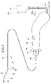
- FIG. 2 shows a casing of a handle of a medical device in cross section and others in plan view.
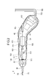
- FIG. 3 is a cross-sectional view showing the tip of the medical device;
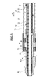
- FIG. 4 is a cross-sectional view showing a portion closer to the proximal end than the distal end of the medical device;
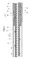
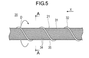
- 4 is a plan view showing a drive shaft;
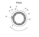
- FIG. 6 is a cross-sectional view along line AA of FIG. 5; FIG.
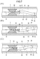
- FIG. 4 is a schematic diagram showing a state in which a lesion is removed by a medical device, in which (A) is a state in which cutting has started, (B) is a state in which cutting is being performed by rotating the outer tube shaft, and (C) is an outer tube shaft. It shows the state of cutting while moving the pipe shaft.
- distal side the side of a medical device that is inserted into a living body cavity
- proximal side the side of the proximal side
- the medical device 10 is inserted into a blood vessel and used for treatment to destroy and remove thrombi, plaques, atheroma, calcified lesions, etc. in acute and chronic leg ischemia and deep vein thrombosis.
- the objects to be removed are not necessarily limited to thrombi, plaques, atheroma, and calcified lesions, and any object that can exist within a living body lumen can be applicable.
- the medical device 10 includes a long drive shaft 20 that is rotationally driven, an outer tubular shaft 50 that houses the drive shaft 20, a cutting portion 90 that cuts a thrombus or the like, and a drive shaft. It comprises a guidewire lumen tube 40 disposed inside of 20 and a handle 100 .
- the medical device 10 further includes a distal end bearing portion 53 arranged on the distal end side of the outer tube shaft 50 and a rotating shaft 24 arranged between the drive shaft 20 and the cutting portion 60 .
- the outer tube shaft 50 is an elongate tubular body that accommodates the drive shaft 20, as shown in FIGS.
- the outer tube shaft 50 rotates together with the operating section 81 when the operator rotates the operating section 81 fixed to the proximal end portion of the outer tube shaft 50 with a finger. By rotating the outer tube shaft 50, the cutting portion 90 can be directed toward the lesion.
- the outer tube shaft 50 comprises an outer layer 51 , an inner layer 60 and a shaped tip 52 .
- At the tip of the outer layer 51 at least one side hole 55 is formed penetrating from the inner peripheral surface to the outer peripheral surface.
- an operating portion 81 and an anti-kink protector 84 are fixed to the outer peripheral surface of the base end portion of the outer layer 51 .
- the anti-kink protector 84 suppresses kinks at the base end of the outer tube shaft 50 .
- the distal end of outer layer 51 is secured to the proximal end of shaping tip 52 .
- the outer layer 51 preferably has flexibility so that it can be bent within a biological lumen and has high torque transmission properties.
- a constituent material of the outer layer 51 for example, a circular tube made of a metal material or a resin material having a certain degree of strength and having helical slits or grooves formed by laser processing can be used.
- the inner layer 60 is arranged inside the outer layer 51 with a gap as shown in FIG.
- a first lumen 54 is formed between the outer layer 51 and the inner layer 60 for feeding liquid such as physiological saline in the distal direction X.
- At least one through-hole 62 is formed in the inner layer 60 to penetrate from the outer peripheral surface to the inner peripheral surface.
- the tip of the inner layer 60 is secured to the inner peripheral surface of the shaping tip 52 .
- a base end portion of the inner layer 60 protrudes further to the base end side than the outer layer 51 .
- a second lumen 61 is formed inside the inner layer 60 and the shaped distal end 52 on the distal side thereof for expelling an object such as a cut thrombus in the proximal direction.
- the inner layer 60 preferably has a structure that allows it to bend flexibly and maintain its cross-sectional shape even when bent, in order to properly maintain the clearance between it and the rotatable drive shaft 20 that is housed inside.
- the inner layer 60 is formed by embedding a braid wire or a coil wire obtained by braiding a metal wire into a tubular shape in a resin material.
- the shaping tip 52 is located at the tip of the outer tube shaft 50, as shown in FIGS.
- the shaping tip 52 is bent at two bends 58 so that the axis of the proximal end of the shaping tip 52 is offset from the axis of the tip.
- the number of bending portions 58 may be one, or three or more.
- the shaping tip 52 can direct the cutting portion 90 toward the lesion and further press the cutting portion 90 strongly against the lesion.
- the material applicable to the outer layer 51 described above can be applied to the forming material of the shaping tip portion 52 .
- the tip bearing portion 53 is connected to the tip of the outer tube shaft 50 and rotatably supports the rotating shaft 24 that is linked to the tip of the drive shaft 20 .
- a tip bearing 53 is secured to the tip of the shaping tip 52 .
- the tip bearing portion 53 has a tip opening 59 formed on the tip side thereof to take in objects such as a cut thrombus, blood, and liquid released from the side hole 55 into the second lumen 61 .
- the tip of the tip bearing portion 53 is positioned on the proximal end side of the cutting portion 90 .
- the cutting part 90 is a member that cuts and reduces objects such as thrombi, plaques, and calcified lesions. Therefore, "cutting" means applying force to a contacting object to make the object smaller. There are no restrictions on the method of applying force in cutting, or the shape and form of the object after cutting.
- the cutting part 90 has a strength capable of cutting the object described above.
- the cutting portion 90 is fixed to the outer peripheral surface of the tip portion of the drive shaft 20 .
- the cutting portion 90 has a large number of fine abrasive grains on its surface. Alternatively, the cutting portion 90 may have a sharp edge.
- the constituent material of the cutting part 90 preferably has strength enough to cut a thrombus. can be used for
- the drive shaft 20 has a distal end and a proximal end, and transmits rotational force input from the proximal end to the cutting part 90 via the rotating shaft 24 arranged on the distal end.
- the drive shaft 20 is a tubular body with flexibility.
- the drive shaft 20 is defined with a nominal direction of rotation D (the direction of rotation of the drive shaft 20 when the medical device 10 is used for cutting and delivery).
- a distal end portion of the drive shaft 20 is connected to the cutting portion 90
- a proximal end portion of the drive shaft 20 is connected to a power shaft 121 of a drive portion 120 provided on the handle 100 .
- the drive shaft 20 is rotatable inside the outer tube shaft 50 .
- the drive shaft 20 has a multi-layer coil 21 .
- the multilayer coil 21 is formed by layering a plurality of coils.
- the multilayer coil 21 includes an inner coil 30 , an outer coil 31 surrounding the inner coil 30 and a carrier coil 32 surrounding the outer coil 31 .
- the multilayer coil 21 may be a coil having four or more layers.
- the inner coil 30 is formed by winding a plurality of first wires 33 in multiple threads.
- the plurality of first wires 33 are helically wound so as to form one layer by lining up in substantially close contact with each other.
- the plurality of first wires 33 loosens the helix of the first wires 33 and expands the diameter. rolled in the direction. That is, the first wire rod 33 is formed so as to be wound in the rated rotation direction D toward the distal direction X when viewed from the base end side.
- the inner coil 30 has a characteristic of expanding in diameter and contracting along the axis of the coil when the drive shaft 20 receives a load torque while rotating in the rated rotation direction D. As shown in FIG.
- the outer coil 31 is formed by winding a plurality of second wires 34 in multiple threads.
- the plurality of second wires 34 are helically wound so as to form a single layer in close contact with each other.
- the spirals of the second wires 34 are tightened and the diameter of the plurality of second wires 34 is reduced. rolled in the direction. That is, the second wire rod 34 is formed so as to be wound in the direction opposite to the rated rotation direction D toward the distal direction X when viewed from the base end side.
- the outer coil 31 has a characteristic that when the drive shaft 20 receives a load torque while rotating in the rated rotation direction D, the outer coil 31 expands along the axis of the coil while contracting in diameter.
- the outer coil 31 is arranged in close contact with the outer peripheral surface of the inner coil 30 . Therefore, when the drive shaft 20 rotates in the rated rotation direction D and receives a load torque, the inner coil 30 expands in diameter and tries to contract in the axial direction, while the outer coil 31 contracts in the axial direction. The attempt to stretch counteracts the radial and axial displacements of the inner coil 30 and the outer coil 31 . Therefore, the multi-layered coil 21 formed by the inner coil 30 and the outer coil 31 can be less deformed in the radial direction and the axial direction when the drive shaft 20 rotates in the rated rotation direction D.
- the number of wires N1 of the first wire 33 of the inner coil 30 is smaller than the number of wires N2 of the second wire 34 of the outer coil 31 .
- the number of wires N2 of the second wires 34 is at least 2, preferably 6 to 18, more preferably 8 to 18, still more preferably 10 to 16.
- the combination of the number of wires N1 of the first wire 33 and the number of wires N2 of the second wire 34 is not particularly limited. 10, 12 or 14. In this embodiment, as shown in FIG. 6, the number N2 of wires of the second wire 34 is 16, and the number N1 of wires of the first wire 33 is eight.
- the number of wires N1 of the first wire 33 is not particularly limited as long as it is smaller than the number of wires N2 of the second wire 34.
- the wire number ratio Ra which is the ratio (N1/N2) of the wire number N1 of the first wire rod 33 to the wire number N2 of the second wire rod 34, is less than 1, preferably 0.875 or less, more preferably 0.75. 0.625 or less, more preferably 0.625 or less.
- the line ratio Ra is greater than 0, preferably 0.25 or more, more preferably 0.375 or more, and still more preferably 0.5 or more.
- the force with which the inner coil 30 tries to expand is greater than the force with which the outer coil 31 tries to contract, and the outer coil 31 is likely to be plastically deformed.
- the force with which the inner coil 30 tries to expand is smaller than the force with which the outer coil 31 tries to contract, and the inner coil 30 is likely to be plastically deformed.
- the transport coil 32 is arranged in close contact with the outer peripheral surface of the outer coil 31 so as to form the outermost layer of the drive shaft 20 .
- the transport coil 32 is formed by loosely winding the third wire 35 forming the transport coil 32 with a gap.
- the third wire 35 is one in this embodiment, it may be two or more.
- the conveying coil 32 functions as an Archimedian screw (screw pump) when the drive shaft 20 rotates in the rated rotation direction D, and conveys liquids and objects in the proximal direction. For this reason, the third wire rod 35 is formed so as to be wound in the rated rotation direction D toward the distal direction X when viewed from the base end side.
- the transport coil 32 may be formed so as to wind in the direction opposite to the rated rotation direction D toward the distal direction X when viewed from the base end side.
- the conveying coil 32 functions as an Archimedes screw (screw pump) when the drive shaft 20 rotates in the rated rotation direction D, and can convey liquids and objects toward the distal end.
- the transport coil 32 may be arranged in close contact with the inner peripheral surface of the inner coil 30 so as to form the innermost layer of the drive shaft 20 .
- the transport coil 32 can transport the liquid or object inside the drive shaft 20 either distally or proximally depending on the winding direction.
- the transport coil 32 may not be provided on the medical device 10 .
- the constituent materials of the first wire rod 33, the second wire rod 34 and the third wire rod 35 are, for example, stainless steel, Ta, Ti, Pt, Au, W, polyolefins such as polyethylene and polypropylene, polyesters such as polyamide and polyethylene terephthalate, ethylene/ Fluorinated polymers such as tetrafluoroethylene copolymer (ETFE), polyether ether ketone (PEEK), polyimide, and the like can be preferably used.
- Each of the first wire rod 33, the second wire rod 34, and the third wire rod 35 is formed of one single wire, but a wire rod such as a stranded wire, which is formed by assembling a plurality of single wires into one wire, may be used. good.
- the rotating shaft 24 is rotatably supported by a tip bearing portion 53 connected to the tip portion of the outer tube shaft 50 .
- a base end portion of the rotating shaft 24 is fixed to the multilayer coil 21 , and a distal end portion of the rotating shaft 24 is fixed to the cutting portion 90 .
- the rotating shaft 24 is formed with at least one groove-like passage 36 extending along the axis. The passageway 36 allows an object cut by the cutting portion 90 to pass through the inside of the distal end bearing portion 53 in the proximal direction.
- the guidewire lumen tube 40 is a tube disposed inside the drive shaft 20, as shown in FIGS.
- the guidewire lumen tube 40 is formed with a guidewire lumen 41 through which a guidewire passes.
- the guidewire lumen tube 40 prevents the guidewire passing through the guidewire lumen 41 from rubbing against the drive shaft 20 .
- a distal end portion of the guide wire lumen tube 40 protrudes further to the distal side than the drive shaft 20 and is arranged inside the cutting portion 90 .
- the proximal end of the guidewire lumen tube 40 is connected to a proximal tube 107 for leading out the guidewire, which is located in the handle 100, as shown in FIG.
- the handle 100 is a part operated by the operator, as shown in FIGS.
- the handle 100 includes a casing 110 , a driving section 120 , a housing 130 and a liquid feeding section 150 .
- Handle 100 further includes switch 101 , suction tube 102 , delivery tube 103 , discharge tube 105 , electrical cable 106 and proximal tube 107 .
- the casing 110 forms the outer shell of the handle 100.
- Casing 110 houses drive unit 120 , housing 130 , liquid feed tube 103 , part of discharge tube 105 , and part of electric cable 106 .
- a passing hole 111 through which the drive shaft 20, the outer tube shaft 50 and the guide wire lumen tube 40 pass is formed at the distal end of the casing 110.
- the proximal end of the guidewire lumen tube 40 is connected to the proximal end tube 107 .
- the proximal tube 107 has a lumen that communicates with the guidewire lumen 41 and guides the guidewire to the proximal side.
- the drive unit 120 is, for example, a hollow motor.
- Drive section 120 includes a hollow power shaft 121 that rotates with power supplied externally via electrical cable 106 .
- the power shaft 121 accommodates the drive shaft 20 inside and is fixed to the drive shaft 20 .
- the rotation speed of the power shaft 121 is not particularly limited, but is, for example, 5,000 to 200,000 rpm.
- the drive unit 120 is connected to a control device (not shown) and can be controlled from inside or outside the handle 100 .
- the electric cable 106 can be connected to an external power source or control device.
- the switch 101 is a part operated by the operator to drive and stop the drive unit 120 .
- Switch 101 is located on the outer surface of casing 110 . It should be noted that if a battery is provided within the handle 100, the electrical cable 106 is located within the handle 100 and is connected to the battery.
- a control device (not shown) is provided in the handle 100 to process the operation input of the switch 101 and control the driving unit 120 and the liquid feeding unit 150. can be done.
- the operation part 81 is a part operated by the operator's fingers to apply rotational torque to the outer tube shaft 50 .
- An outer tube shaft 50 is fixed inside the operating portion 81 .
- the housing 130 includes a liquid feed port 131 that feeds liquid, and a discharge port 133 that discharges liquid and objects.
- the liquid feed port 131 communicates with the first lumen 54 formed between the outer layer 51 and the inner layer 60 of the outer tube shaft 50 .
- the liquid feeding port 131 is connected to the liquid feeding tube 103 and can receive the liquid from the liquid feeding tube 103 .
- the liquid sent to the liquid sending port 131 can flow into the first lumen 54 of the outer tube shaft 50 .
- the outlet 133 communicates with a second lumen 61 formed between the outer tubular shaft 50 and the drive shaft 20 .
- the discharge port 133 is connected to the discharge tube 105 .
- the outlet 133 can receive liquids or objects from the second lumen 61 and drain them to the outlet tube 105 .
- the liquid sending unit 150 is a pump that sends liquid to the housing 130 via the liquid sending tube 103 .
- the liquid feeding unit 150 is connected to the suction tube 102 that receives liquid such as physiological saline from a liquid feeding source outside the casing 110 , and can suck the liquid from the suction tube 102 .
- the liquid sending unit 150 is connected to the liquid sending tube 103 and can discharge the sucked liquid to the liquid sending tube 103 .
- the external liquid supply source is, for example, the physiological saline solution bag 160, but is not limited to this.
- the liquid sending unit 150 may be provided outside instead of being provided on the handle 100 .
- the liquid feeding unit 150 is not limited to a pump as long as it can generate liquid feeding pressure, and may be, for example, a syringe, a bag suspended from a drip tower, or a pressure bag. Further, for example, by using the conveying force of the conveying coil 32 of the drive shaft 20, the liquid sending section 150 does not need to be equipped with a pump.
- the direction in which the transport coil 32 is wound is the direction in which the drive shaft 20 rotates in the rated rotation direction so that the transport coil 32 can exert a force toward the tip side on the liquid.
- a physiological saline solution bag 160 functioning as a liquid feeding part is connected to the discharge port 133 functioning as a liquid feeding port.
- the rotating conveying coil 32 can convey the physiological saline supplied from the physiological saline bag 160 to the second lumen 61 through the discharge port 133 in the distal direction.
- the discharge tube 105 is a tube for discharging liquids and objects to the outside of the casing 110 .
- the drain tube 105 is connected to a waste bag 161 that can contain liquids or objects, for example.
- the discharge tube 105 may be connected to a suction source capable of actively sucking, such as a pump or a syringe.
- the operator inserts the guide wire W into the blood vessel to reach the vicinity of the lesion L.
- the operator inserts the proximal end of the guidewire W into the guidewire lumen 41 of the medical device 10 .
- the cutting portion 90 of the medical device 10 is moved to the vicinity of the lesion L using the guide wire W as a guide.
- the operator operates the switch 101 to start the operation of the driving section 120 and the liquid feeding section 150 .
- the power shaft 121 of the drive unit 120 rotates, and the drive shaft 20 fixed to the power shaft 121 and the cutting unit 90 connected to the drive shaft 20 via the rotation shaft 24 rotate.
- the operator can cut the lesion L with the cutting part 90 .
- the conveying coil 32 arranged on the outer peripheral surface of the drive shaft 20 generates a force for conveying the liquid or the object in the second lumen 61 to the base end side. Let Thereby, as shown in FIGS. 3 and 7(A), a conveying force acts on the tip opening 59 of the outer tube shaft 50 .
- the operator can operate the operation part 81 shown in FIGS.
- the operation rotor 82 When the operator rotates the operation rotor 82, the outer tube shaft 50 fixed to the operation portion 81 rotates.
- the outer tube shaft 50 rotates, as shown in FIG. 7(B), the position and direction of the tip side portion of the outer tube shaft 50 relative to the bent portion 58 change, and the position and direction of the cutting portion 90 can be changed. Accordingly, cutting can be performed while changing the position and direction of the cutting portion 90 only by operating the operation portion 81 without rotating the entire handle 100, which is difficult to rotate greatly.
- the operator moves the entire handle 100 or the outer tube shaft 50 exposed outside the body to reciprocate the outer tube shaft 50 along the longitudinal direction of the blood vessel.
- the cutting portion 90 can cut the lesion L along the longitudinal direction of the blood vessel.
- the physiological saline solution that has entered the first lumen 54 from the liquid feed port 131 moves in the distal direction.
- Physiological saline solution flowing distally through the first lumen 54 is discharged into the blood vessel from a side hole 55 formed at the distal end of the outer layer 51, as shown in FIGS.
- part of the physiological saline flowing in the distal direction through the first lumen 54 passes through the through hole 62 and flows into the inner second lumen 61 .
- a portion of the physiological saline solution released into the blood vessel is conveyed along with the blood and the cut object from the distal end opening 59 of the outer tube shaft 50 to the second lumen 61, as shown in FIGS. .
- Objects and liquids that enter the second lumen 61 move through the second lumen 61 in the proximal direction.
- Objects and blood conveyed to the second lumen 61 are diluted by the physiological saline discharged into the blood vessel through the side hole 55 .
- objects and liquids delivered to the second lumen 61 are diluted by the saline flowing directly into the second lumen 61 through the through-holes 62, as shown in FIG. Therefore, it is possible to reduce the viscosity of the discharged matter and suppress the formation of a thrombus in the second lumen 61 .
- the inner coil 30 and the outer coil 31 have different coil diameters.
- the inner coil 30 and the outer coil 31 behave differently, such that the outer coil 31 experiences a tensile force when a compressive force acts on 30 . Therefore, by making the number of wires N1 of the first wire 33 of the inner coil 30 and the number of wires N2 of the second wire 34 of the outer coil 31 different, the contracting force of the outer coil 31 and the expanding force of the inner coil 30 can be obtained. can be adjusted for proper balance.
- the drive shaft 20 may be twisted inside the outer tube shaft 50 so that the center of the coil draws a spiral. Even in such a case, the drive shaft 20 is resistant to plastic deformation and can maintain an appropriate structure, so that the operation can be continued. Also, if the drive shaft 20 is twisted inside the outer tube shaft 50 so that the coil center draws a spiral, there is a possibility that the drive shaft 20 will come into contact with the outer tube shaft 50 on the outside and the guide wire lumen tube 40 on the inside.
- the operator presses the switch 101 .
- the rotation of the drive shaft 20 is stopped, and the liquid feeding by the liquid feeding section 150 is stopped.
- the operator removes the medical device 10 from the blood vessel, completing the treatment.
- a multi-layered coil 21 with a different two-layer structure was created by setting the number of wires N2 of the second wire 34 of the outer coil 31 to 16 and changing the number of wires N1 of the first wire 33 of the inner coil 30 .
- the number of wires N1 of the first wire 33 in Example 1 is 4, the number of wires N1 of the first wire 33 in Example 2 is 6, and the number of wires N1 of the first wire 33 in Example 3 is 8.
- the number of wires N1 of the first wire 33 of Example 4 is 10, the number of wires N1 of the first wire 33 of Example 5 is 12, the number of wires N1 of the first wire 33 of Example 6 is 14, and the number of wires N1 of the first wire 33 of Comparative Example 1 is 14.
- the number of wires N1 of the first wire rod 33 was 16 wires.
- the outer diameter of the multilayer coil 21 is 1.0 mm
- the inner diameter is 0.7 mm
- the wire diameter of the first wire 33 is 0.075 mm
- the wire diameter of the second wire 34 is 0.075 mm.
- the material of the first wire rod 33 was SUS304WPB
- the material of the second wire rod 34 was SUS304WPB.
- the prepared multilayer coil 21 was cut to a length of about 300 mm and placed in a polyimide tube with an inner diameter of 1.35 mm. Next, torque was applied to the multilayer coil 21 until the multilayer coil 21 was plastically deformed, and the torque value at the time of plastic deformation was measured.
- Table 1 shows the results when the multilayer coil 21 is arranged linearly and torque is applied
- Table 2 shows the results when the multilayer coil 21 is curved with a radius of curvature of 15 mm and torque is applied.
- Examples 1 to 6 with a wire number ratio Ra of less than 1 have higher torsional strength than Comparative Example 1 with a wire number ratio Ra of 1. rice field. Furthermore, in Table 1, higher torsional strength is obtained in Examples 1 to 6 with a line ratio Ra of 0.875 or less, and higher torsional strength is obtained in Examples 1 to 5 with a line ratio Ra of 0.75 or less. was obtained, and higher torsional strength was obtained in Examples 1 to 4 in which the line ratio Ra was 0.625 or less.
- Examples 1 to 6 with a wire ratio Ra of less than 1 had a higher torsional strength than Comparative Example 1 with a wire ratio Ra of 1. .
- higher torsional strength is obtained in Examples 1 to 6 in which the line ratio Ra is 0.875 or less, and higher torsional strength is obtained in Examples 1 to 5 in which the line ratio Ra is 0.75 or less. is obtained, higher torsional strength is obtained in Examples 1 to 4 in which the line ratio Ra is 0.625 or less, and higher torsional strength is obtained in Examples 1 to 3 in which the line ratio Ra is 0.5 or less.
- Higher torsional strength was obtained in Examples 1 and 2 in which the line ratio Ra was 0.375 or less, and higher torsional strength was obtained in Example 1 in which the line ratio Ra was 0.25 or less.
- the medical device 10 is a long medical device 10 that can be inserted into a biological lumen, has a distal end and a proximal end, and receives a driving force from the proximal end side.
- a drive shaft 20 capable of rotating to transmit a rotational force in the distal direction X and having a specified rated rotation direction D is provided. It has an inner coil 30 formed by winding and an outer coil 31 formed by winding a plurality of second wires 34 side by side in the circumferential direction of the drive shaft 20 and surrounding the inner coil 30 .
- the wire rod 33 is wound in the rated rotation direction D in the distal direction X when viewed from the base end side, and the second wire rod 34 of the outer coil 31 is wound in the rated rotation direction D in the distal direction X when viewed from the proximal side.
- the number of wires N1 of the first wire 33 forming the inner coil 30 is smaller than the number N2 of wires of the second wire 34 forming the outer coil 31 .
- the wire number N1 of the inner coil 30 is smaller than the wire number N2 of the outer coil 31, so that when the drive shaft 20 rotates in the rated rotation direction D, the outer coil 31 is
- the balance between the contracting force and the expanding force of the inner coil 30 is improved, and the torsional rigidity of the drive shaft 20 can be improved. Therefore, the medical device 10 can suppress plastic deformation of the drive shaft 20 due to strong torque, and can maintain the structure of the drive shaft 20 appropriately.
- the medical device 10 can simultaneously achieve smooth rotation and high torsional rigidity in severe bending lesions.
- the number of wires N1 of the inner coil 30 is preferably 0.75 times or less the number of wires N2 of the outer coil 31.
- the medical device 10 can suppress plastic deformation of the drive shaft 20 due to strong torque, and can maintain the structure of the drive shaft 20 appropriately. Furthermore, the medical device 10 can simultaneously achieve smooth rotation and high torsional stiffness in severe bending lesions.
- the drive shaft 20 has a transport coil 32 formed by spirally winding at least one third wire 35 with a gap in the longitudinal direction of the drive shaft 20 . It forms the outermost layer or innermost layer of the shaft 20 .
- the conveying coil 32 functioning as an Archimedes screw (screw pump) applies a force toward the proximal side or the distal side to the object or liquid, thereby conveying the object or liquid.
- the transport coil 32 may not be provided.
- the medical device 10 also has an elongated inner member (eg, guidewire lumen tube 40) arranged inside the drive shaft 20. Since the drive shaft 20 of the present medical device 10 is easy to maintain its structure, even if the guide wire lumen tube 40 is arranged inside the drive shaft 20, the drive shaft 20 contacts the guide wire lumen tube 40 and the drive shaft 20 is removed. Alternatively, breakage of the guidewire lumen tube 40 can be suppressed. Even if the drive shaft 20 receives a load torque while rotating in the rated rotation direction D and the coil center is twisted in a spiral manner, the drive shaft 20 can easily maintain its structure. Therefore, it is possible to effectively suppress damage to the drive shaft 20 or the guidewire lumen tube 40 due to the drive shaft 20 contacting the guidewire lumen tube 40 .
- the inner member is not limited to a hollow member like the guidewire lumen tube 40, and may be a solid core member, for example.
- the medical device 10 also has a cutting section 90 that is indirectly connected to the distal end of the drive shaft 20 and capable of cutting an object.
- the drive shaft 20 is subjected to a strong torque.
- the medical device 10 can suppress plastic deformation of the drive shaft 20 as described above even if it receives a strong torque. Therefore, the medical device 10 can appropriately maintain the structure of the drive shaft 20 even when the cutting portion 90 is provided.
- the cutting portion 90 may be directly connected to the distal end portion of the drive shaft 20 .
- the medical device 10 may not include the cutting portion 90 as long as it includes a torqued drive shaft 20 .
- drive shaft 20 may be provided for conveying force by conveying coil 32 rather than cutting.
- the biological lumen into which the medical device 10 is inserted is not limited to blood vessels, and may be, for example, vessels, ureters, bile ducts, fallopian tubes, hepatic ducts, and the like.
Abstract
Provided is a medical device in which the structure of a drive shaft can be properly maintained even when subjected to a strong torque. A long medical device (10) that can be inserted into a biological lumen includes a drive shaft (20) which has a distal end and a proximal end and has a designated rated direction of rotation (D), and when the drive shaft is subjected to a drive force from the proximal end, is capable of rotating to transmit a rotational force in the direction toward the distal end. The drive shaft (20) has an inner coil (30) formed by winding a plurality of wires side-by-side in the circumferential direction of the drive shaft (20), and an outer coil (31) that surrounds the inner coil (30) and that is formed by winding a plurality of wires side-by-side in the circumferential direction of the drive shaft (20). The wires of the inner coil (30) are wound in the rated direction of rotation (D) as viewed along the direction from the proximal end side toward the distal end. The wires of the outer coil (31) are wound in the opposite direction to the rated direction of rotation (D) as viewed along the direction from the proximal end side toward the distal end. The number of wires (N1) of first wires (33) that form the inner coil (30) is smaller than the number of wires (N2) of second wires (34) that form the outer coil (31).
Description
本発明は、生体管腔に挿入される医療デバイスに関する。
The present invention relates to medical devices that are inserted into biological lumens.
血管内のプラークや血栓などによる狭窄部の治療方法は、バルーンにより血管を拡張する方法や、網目状またはコイル状のステントを血管の支えとして血管内に留置する方法などが挙げられる。しかしながら、これらの方法では、石灰化により硬くなっているプラーク等からなる狭窄部や、血管の分岐部で生じている狭窄部を治療することは、困難である。このような場合においても治療が可能なデバイスとして、アテレクトミーデバイスがある(例えば、特許文献1を参照)。
Treatment methods for stenosis caused by plaque or thrombus in blood vessels include dilating blood vessels with balloons and placing mesh-like or coil-like stents in the blood vessels as a support for the blood vessels. However, with these methods, it is difficult to treat a stenotic part composed of plaque hardened by calcification or a stenotic part occurring at a bifurcation of a blood vessel. There is an atherectomy device as a device capable of treatment even in such cases (see, for example, Patent Document 1).
アテレクトミーデバイスは、高速回転する切削部により、血管内のプラークを剪断/破砕することで除去するデバイスである。アテレクトミーデバイスには、カテーテルの先端に配置される切削部品の高速回転を体外から伝達する駆動シャフトが、カテーテル内部に配置される。
An atherectomy device is a device that removes plaque in blood vessels by shearing/crushing it with a cutting part that rotates at high speed. In the atherectomy device, a drive shaft is placed inside the catheter that transmits from outside the body the high-speed rotation of a cutting part placed at the tip of the catheter.
駆動シャフトは、安定した高速回転性と、プラーク等の病変を切削する際のトルク負荷に対する十分な耐久性を有する必要がある。駆動シャフトを、単層コイルを用いて実現している事例は複数ある。しかしながら、単層コイルで実現された駆動シャフトは、強いトルク負荷を受けた場合に、コイルに塑性変形が発生し、中空構造を適切に維持できない可能性がある。
The drive shaft must have stable high-speed rotation and sufficient durability against torque load when cutting lesions such as plaque. There are several examples of driving shafts being implemented using single-layer coils. However, when a drive shaft realized with a single layer coil is subjected to a strong torque load, plastic deformation of the coil may occur and the hollow structure may not be properly maintained.
本発明は、上述した課題を解決するためになされたものであり、強いトルクを受けても駆動シャフトの構造を適切に維持できる医療デバイスを提供することを目的とする。
The present invention has been made to solve the above-mentioned problems, and aims to provide a medical device that can appropriately maintain the structure of the drive shaft even when subjected to strong torque.
上記目的を達成する本発明に係る医療デバイスは、生体管腔内に挿入可能な長尺な医療デバイスであって、先端および基端を有し、基端側から駆動力を受けて回転して先端方向へ回転力を伝達可能であり、定格回転方向が指定された駆動シャフトを有し、前記駆動シャフトは、複数の線材を前記駆動シャフトの周方向に並べて巻いて形成された内側コイルと、複数の線材を前記駆動シャフトの周方向に並べて巻いて形成され、前記内側コイルを囲む外側コイルと、を有し、前記内側コイルの線材は、基端側から見て先端方向へ向かうにつれて定格回転方向へ巻かれ、前記外側コイルの線材は、基端側から見て先端方向へ向かうにつれて定格回転方向の反対方向へ巻かれ、前記内側コイルを形成する線材の数は、前記外側コイルを形成する線材の数よりも少ない。
A medical device according to the present invention for achieving the above object is a long medical device that can be inserted into a biological lumen, has a distal end and a proximal end, and rotates by receiving a driving force from the proximal end side. a drive shaft capable of transmitting a rotational force in a distal direction and having a specified rated rotation direction, the drive shaft having an inner coil formed by winding a plurality of wire rods arranged in a circumferential direction of the drive shaft; an outer coil formed by winding a plurality of wire rods side by side in the circumferential direction of the drive shaft and surrounding the inner coil; the wire rod of the outer coil is wound in the opposite direction of the rated rotation direction as viewed from the proximal side toward the distal direction, and the number of wire rods forming the inner coil forms the outer coil Less than the number of wires.
上記のように構成した医療デバイスは、内側コイルを形成する線材の数が外側コイルを形成する線材の数よりも小さいことで、駆動シャフトが定格回転方向へ回転する際に、外側コイルが収縮する力と内側コイルが拡張する力のバランスが向上し、駆動シャフトのねじれ剛性を向上できる。このため、本医療デバイスは、強いトルクを受けて駆動シャフトが塑性変形することを抑制し、駆動シャフトの構造を適切に維持できる。
In the medical device configured as described above, the number of wires forming the inner coil is smaller than the number of wires forming the outer coil, so that the outer coil contracts when the drive shaft rotates in the rated rotation direction. A better balance between the force and the expanding force of the inner coil can improve the torsional rigidity of the drive shaft. Therefore, the present medical device can suppress plastic deformation of the drive shaft due to strong torque, and can appropriately maintain the structure of the drive shaft.
以下、図面を参照して、本発明の実施の形態を説明する。なお、図面における各部材の大きさや比率は、説明の都合上誇張され実際の大きさや比率とは異なる場合がある。また、本明細書では、医療デバイスの生体内腔に挿入する側を「先端側」、操作する側を「基端側」と称することとする。
Hereinafter, embodiments of the present invention will be described with reference to the drawings. Note that the size and ratio of each member in the drawings may be exaggerated for convenience of explanation and may differ from the actual size and ratio. Also, in this specification, the side of a medical device that is inserted into a living body cavity is referred to as the "distal side", and the side that is operated is referred to as the "proximal side".
本実施形態に係る医療デバイス10は、急性及び慢性下肢虚血や深部静脈血栓症において、血管内に挿入され、血栓、プラーク、アテローム、石灰化病変等を破壊して除去する処置に用いられる。なお、除去する物体は、必ずしも血栓、プラーク、アテローム、石灰化病変に限定されず、生体管腔内に存在し得る物体は、全て該当し得る。
The medical device 10 according to this embodiment is inserted into a blood vessel and used for treatment to destroy and remove thrombi, plaques, atheroma, calcified lesions, etc. in acute and chronic leg ischemia and deep vein thrombosis. Note that the objects to be removed are not necessarily limited to thrombi, plaques, atheroma, and calcified lesions, and any object that can exist within a living body lumen can be applicable.
医療デバイス10は、図1に示すように、長尺であって回転駆動される駆動シャフト20と、駆動シャフト20を収容する外管シャフト50と、血栓等を切削する切削部90と、駆動シャフト20の内部に配置されるガイドワイヤルーメンチューブ40と、ハンドル100とを備えている。医療デバイス10は、さらに、外管シャフト50の先端側に配置される先端軸受部53と、駆動シャフト20および切削部60の間に配置される回転軸24とを備えている。
As shown in FIG. 1, the medical device 10 includes a long drive shaft 20 that is rotationally driven, an outer tubular shaft 50 that houses the drive shaft 20, a cutting portion 90 that cuts a thrombus or the like, and a drive shaft. It comprises a guidewire lumen tube 40 disposed inside of 20 and a handle 100 . The medical device 10 further includes a distal end bearing portion 53 arranged on the distal end side of the outer tube shaft 50 and a rotating shaft 24 arranged between the drive shaft 20 and the cutting portion 60 .
外管シャフト50は、図1、3および4に示すように、駆動シャフト20を収容する長尺な管体である。外管シャフト50は、術者が外管シャフト50の基端部に固定される操作部81を指で回転させることで、操作部81と共に回転する。外管シャフト50は回転することで、切削部90を病変部に向けることができる。外管シャフト50は、外層51と、内層60と、形状付け先端部52とを備えている。
The outer tube shaft 50 is an elongate tubular body that accommodates the drive shaft 20, as shown in FIGS. The outer tube shaft 50 rotates together with the operating section 81 when the operator rotates the operating section 81 fixed to the proximal end portion of the outer tube shaft 50 with a finger. By rotating the outer tube shaft 50, the cutting portion 90 can be directed toward the lesion. The outer tube shaft 50 comprises an outer layer 51 , an inner layer 60 and a shaped tip 52 .
外層51の先端部には、内周面から外周面へ貫通する少なくとも1つの側孔55が形成される。外層51の基端部の外周面には、図1および2に示すように、操作部81と、耐キンクプロテクタ84とが固定されている。耐キンクプロテクタ84は、外管シャフト50の基端部におけるキンクを抑制する。外層51の先端部は、形状付け先端部52の基端部に固定されている。外層51は、生体管腔内で曲がるように柔軟性を備え、かつ高いトルク伝達性を備えることが好ましい。外層51の構成材料は、例えばある程度の強度を有する金属材料や樹脂材料からなる円管に、レーザー加工により、螺旋状のスリットや溝を形成したものを使用できる。
At the tip of the outer layer 51, at least one side hole 55 is formed penetrating from the inner peripheral surface to the outer peripheral surface. As shown in FIGS. 1 and 2, an operating portion 81 and an anti-kink protector 84 are fixed to the outer peripheral surface of the base end portion of the outer layer 51 . The anti-kink protector 84 suppresses kinks at the base end of the outer tube shaft 50 . The distal end of outer layer 51 is secured to the proximal end of shaping tip 52 . The outer layer 51 preferably has flexibility so that it can be bent within a biological lumen and has high torque transmission properties. As a constituent material of the outer layer 51, for example, a circular tube made of a metal material or a resin material having a certain degree of strength and having helical slits or grooves formed by laser processing can be used.
内層60は、図4に示すように、外層51の内側に隙間を有して配置される。外層51と内層60の間には、生理食塩液等の液体を先端方向Xへ送液するための第1ルーメン54が形成される。内層60には、外周面から内周面へ貫通する少なくとも1つの貫通孔62が形成される。内層60の先端部は、形状付け先端部52の内周面に固定されている。内層60の基端部は、外層51よりも基端側へ突出している。内層60およびその先端側の形状付け先端部52の内側には、切削した血栓等の物体を基端方向へ排出するための第2ルーメン61が形成されている。
The inner layer 60 is arranged inside the outer layer 51 with a gap as shown in FIG. A first lumen 54 is formed between the outer layer 51 and the inner layer 60 for feeding liquid such as physiological saline in the distal direction X. As shown in FIG. At least one through-hole 62 is formed in the inner layer 60 to penetrate from the outer peripheral surface to the inner peripheral surface. The tip of the inner layer 60 is secured to the inner peripheral surface of the shaping tip 52 . A base end portion of the inner layer 60 protrudes further to the base end side than the outer layer 51 . A second lumen 61 is formed inside the inner layer 60 and the shaped distal end 52 on the distal side thereof for expelling an object such as a cut thrombus in the proximal direction.
内層60は、内側に収容する回転可能な駆動シャフト20との間の隙間を適切に維持するために、柔軟に曲がることができつつ、曲がっても断面形状を維持できる構造を備えることが好ましい。このために、内層60は、樹脂材料に、金属線を管状に編組したブレード線、もしくはコイル線が埋設されて形成される。
The inner layer 60 preferably has a structure that allows it to bend flexibly and maintain its cross-sectional shape even when bent, in order to properly maintain the clearance between it and the rotatable drive shaft 20 that is housed inside. For this purpose, the inner layer 60 is formed by embedding a braid wire or a coil wire obtained by braiding a metal wire into a tubular shape in a resin material.
形状付け先端部52は、図1、3および4に示すように、外管シャフト50の先端部に位置する。形状付け先端部52は、当該形状付け先端部52の基端部の軸心と先端部の軸心がずれるように2か所の屈曲部58で曲げられている。なお、屈曲部58の数は、1か所であっても、3か所以上であってもよい。形状付け先端部52は、外管シャフト50を回転させることで、切削部90を病変部に向け、さらに切削部90を病変部に対して強く押し付けることができる。形状付け先端部52の構成材料は、例えば、前述した外層51に適用可能な材料を適用できる。特に、形状付け先端部52の構成材料は、超弾性を有するNiTi合金を用いることが好ましい。
The shaping tip 52 is located at the tip of the outer tube shaft 50, as shown in FIGS. The shaping tip 52 is bent at two bends 58 so that the axis of the proximal end of the shaping tip 52 is offset from the axis of the tip. The number of bending portions 58 may be one, or three or more. By rotating the outer tube shaft 50, the shaping tip 52 can direct the cutting portion 90 toward the lesion and further press the cutting portion 90 strongly against the lesion. For example, the material applicable to the outer layer 51 described above can be applied to the forming material of the shaping tip portion 52 . In particular, it is preferable to use a NiTi alloy having superelasticity as a constituent material of the shaping tip portion 52 .
先端軸受部53は、図3に示すように、外管シャフト50の先端部に連結されて、駆動シャフト20の先端部に連結される回転軸24を回転可能に支持している。先端軸受部53は、形状付け先端部52の先端部に固定させている。先端軸受部53は、先端側に、切削した血栓等の物体、血液、側孔55から放出された液体を第2ルーメン61に取り込む先端開口部59が形成されている。先端軸受部53の先端は、切削部90の基端側に位置している。
As shown in FIG. 3, the tip bearing portion 53 is connected to the tip of the outer tube shaft 50 and rotatably supports the rotating shaft 24 that is linked to the tip of the drive shaft 20 . A tip bearing 53 is secured to the tip of the shaping tip 52 . The tip bearing portion 53 has a tip opening 59 formed on the tip side thereof to take in objects such as a cut thrombus, blood, and liquid released from the side hole 55 into the second lumen 61 . The tip of the tip bearing portion 53 is positioned on the proximal end side of the cutting portion 90 .
切削部90は、血栓、プラークや石灰化病変等の物体を切削して小さくする部材である。したがって、“切削”とは、接触する物体に力を作用させて、物体を小さくすることを意味する。切削における力の作用方法や、切削後の物体の形状や形態は、限定されない。切削部90は、上述した物体を切削できる強度を有している。切削部90は、駆動シャフト20の先端部の外周面に固定されている。切削部90は、表面に、微小な砥粒を多数有している。または、切削部90は、鋭利な刃を備えてもよい。
The cutting part 90 is a member that cuts and reduces objects such as thrombi, plaques, and calcified lesions. Therefore, "cutting" means applying force to a contacting object to make the object smaller. There are no restrictions on the method of applying force in cutting, or the shape and form of the object after cutting. The cutting part 90 has a strength capable of cutting the object described above. The cutting portion 90 is fixed to the outer peripheral surface of the tip portion of the drive shaft 20 . The cutting portion 90 has a large number of fine abrasive grains on its surface. Alternatively, the cutting portion 90 may have a sharp edge.
切削部90の構成材料は、血栓を切削できる程度の強度を有することが好ましく、例えば、ステンレス、Ta、Ti、Pt、Au、W、NiTi合金、形状記憶合金、超鋼合金、セラミクスなどが好適に使用できる。
The constituent material of the cutting part 90 preferably has strength enough to cut a thrombus. can be used for
駆動シャフト20は、図1~6に示すように、先端および基端を有し、基端側から入力される回転力を先端側に配置される回転軸24を介して切削部90に伝達する、可撓性を備えた管体である。駆動シャフト20は、定格回転方向D(医療デバイス10を切削および搬送のために使用する際の駆動シャフト20の回転方向)が規定されている。駆動シャフト20の先端部は、切削部90に連結され、駆動シャフト20の基端部は、ハンドル100に設けられる駆動部120の動力シャフト121に連結される。駆動シャフト20は、外管シャフト50の内部で回転可能である。駆動シャフト20は、多層コイル21を備えている。
As shown in FIGS. 1 to 6, the drive shaft 20 has a distal end and a proximal end, and transmits rotational force input from the proximal end to the cutting part 90 via the rotating shaft 24 arranged on the distal end. , is a tubular body with flexibility. The drive shaft 20 is defined with a nominal direction of rotation D (the direction of rotation of the drive shaft 20 when the medical device 10 is used for cutting and delivery). A distal end portion of the drive shaft 20 is connected to the cutting portion 90 , and a proximal end portion of the drive shaft 20 is connected to a power shaft 121 of a drive portion 120 provided on the handle 100 . The drive shaft 20 is rotatable inside the outer tube shaft 50 . The drive shaft 20 has a multi-layer coil 21 .
多層コイル21は、複数のコイルが層状に重ねられて形成される。多層コイル21は、内側コイル30と、内側コイル30の外側を囲む外側コイル31と、外側コイル31の外側を囲む搬送コイル32とを備えている。なお、多層コイル21は、4層以上のコイルであってもよい。
The multilayer coil 21 is formed by layering a plurality of coils. The multilayer coil 21 includes an inner coil 30 , an outer coil 31 surrounding the inner coil 30 and a carrier coil 32 surrounding the outer coil 31 . Note that the multilayer coil 21 may be a coil having four or more layers.
内側コイル30は、複数の第1線材33が多条に巻かれて形成されている。複数の第1線材33は、略密着して並んで1つの層を形成するように螺旋状に巻かれている。複数の第1線材33は、駆動シャフト20が基端側からトルクを受けて定格回転方向Dへ回転中に先端側から負荷トルクを受ける際に、第1線材33の螺旋が緩んで拡径する方向へ巻かれている。すなわち、第1線材33は、基端側から見て、先端方向Xへ向かうにつれて定格回転方向Dへ巻くように形成される。内側コイル30は、駆動シャフト20が定格回転方向Dへ回転中に負荷トルクを受ける際に、拡径しつつコイルの軸心に沿って収縮する特性を有する。
The inner coil 30 is formed by winding a plurality of first wires 33 in multiple threads. The plurality of first wires 33 are helically wound so as to form one layer by lining up in substantially close contact with each other. When the drive shaft 20 receives torque from the base end side and receives load torque from the tip side while rotating in the rated rotation direction D, the plurality of first wires 33 loosens the helix of the first wires 33 and expands the diameter. rolled in the direction. That is, the first wire rod 33 is formed so as to be wound in the rated rotation direction D toward the distal direction X when viewed from the base end side. The inner coil 30 has a characteristic of expanding in diameter and contracting along the axis of the coil when the drive shaft 20 receives a load torque while rotating in the rated rotation direction D. As shown in FIG.
外側コイル31は、複数の第2線材34が多条に巻かれて形成されている。複数の第2線材34は、略密着して並んで1つの層を形成するように螺旋状に巻かれている。複数の第2線材34は、駆動シャフト20が基端側からトルクを受けて定格回転方向Dへ回転中に先端側から負荷トルクを受ける際に、第2線材34の螺旋が締まって縮径する方向へ巻かれている。すなわち、第2線材34は、基端側から見て、先端方向Xへ向かうにつれて定格回転方向Dの反対方向へ巻くように形成される。外側コイル31は、駆動シャフト20が定格回転方向Dへ回転中に負荷トルクを受ける際に、縮径しつつコイルの軸心に沿って伸長する特性を有する。
The outer coil 31 is formed by winding a plurality of second wires 34 in multiple threads. The plurality of second wires 34 are helically wound so as to form a single layer in close contact with each other. When the drive shaft 20 receives torque from the base end side and receives load torque from the tip side while rotating in the rated rotation direction D, the spirals of the second wires 34 are tightened and the diameter of the plurality of second wires 34 is reduced. rolled in the direction. That is, the second wire rod 34 is formed so as to be wound in the direction opposite to the rated rotation direction D toward the distal direction X when viewed from the base end side. The outer coil 31 has a characteristic that when the drive shaft 20 receives a load torque while rotating in the rated rotation direction D, the outer coil 31 expands along the axis of the coil while contracting in diameter.
外側コイル31は、内側コイル30の外周面に密着して配置される。このため、駆動シャフト20が定格回転方向Dへ回転して負荷トルクを受ける際に、内側コイル30は拡径しつつ軸心方向へ収縮しようとし、外側コイル31は縮径しつつ軸心方向へ伸長しようとすることで、内側コイル30および外側コイル31の径方向および軸心方向の変位が相殺される。このため、内側コイル30および外側コイル31により形成される多層コイル21は、駆動シャフト20が定格回転方向Dへ回転する際に、径方向および軸心方向への変形を小さくできる。
The outer coil 31 is arranged in close contact with the outer peripheral surface of the inner coil 30 . Therefore, when the drive shaft 20 rotates in the rated rotation direction D and receives a load torque, the inner coil 30 expands in diameter and tries to contract in the axial direction, while the outer coil 31 contracts in the axial direction. The attempt to stretch counteracts the radial and axial displacements of the inner coil 30 and the outer coil 31 . Therefore, the multi-layered coil 21 formed by the inner coil 30 and the outer coil 31 can be less deformed in the radial direction and the axial direction when the drive shaft 20 rotates in the rated rotation direction D.
内側コイル30の第1線材33の線数N1は、外側コイル31の第2線材34の線数N2よりも少ない。第2線材34の線数N2は、少なくとも2本であり、好ましくは6本~18本、より好ましくは8本~18本、さらに好ましくは10本~16本である。第1線材33の線数N1と第2線材34の線数N2の組み合わせは、特に限定されないが、例えば線数N2が16本の場合に、線数N1が4本、6本、8本、10本、12本または14本である。本実施形態においては、図6に示すように、第2線材34の線数N2は16本であり、第1線材33の線数N1は8本である。
The number of wires N1 of the first wire 33 of the inner coil 30 is smaller than the number of wires N2 of the second wire 34 of the outer coil 31 . The number of wires N2 of the second wires 34 is at least 2, preferably 6 to 18, more preferably 8 to 18, still more preferably 10 to 16. The combination of the number of wires N1 of the first wire 33 and the number of wires N2 of the second wire 34 is not particularly limited. 10, 12 or 14. In this embodiment, as shown in FIG. 6, the number N2 of wires of the second wire 34 is 16, and the number N1 of wires of the first wire 33 is eight.
第1線材33の線数N1は、第2線材34の線数N2よりも少なければ、特に限定されない。第2線材34の線数N2に対する第1線材33の線数N1の比率(N1/N2)である線数比Raは、1未満であり、好ましくは0.875以下、より好ましくは0.75以下、さらに好ましくは0.625以下である。さらに、線数比Raは、0より大きく、好ましくは0.25以上、より好ましくは0.375以上、さらに好ましくは0.5以上である。線数比Raが1に近いと、内側コイル30が拡張しようとする力が、外側コイル31が収縮しようとする力よりも大きく、外側コイル31が塑性変形しやすいと考えられる。線数比Raが0に近いと、内側コイル30が拡張しようとする力が、外側コイル31が収縮しようとする力よりも小さく、内側コイル30が塑性変形しやすいと考えられる。
The number of wires N1 of the first wire 33 is not particularly limited as long as it is smaller than the number of wires N2 of the second wire 34. The wire number ratio Ra, which is the ratio (N1/N2) of the wire number N1 of the first wire rod 33 to the wire number N2 of the second wire rod 34, is less than 1, preferably 0.875 or less, more preferably 0.75. 0.625 or less, more preferably 0.625 or less. Furthermore, the line ratio Ra is greater than 0, preferably 0.25 or more, more preferably 0.375 or more, and still more preferably 0.5 or more. When the wire ratio Ra is close to 1, the force with which the inner coil 30 tries to expand is greater than the force with which the outer coil 31 tries to contract, and the outer coil 31 is likely to be plastically deformed. When the wire ratio Ra is close to 0, the force with which the inner coil 30 tries to expand is smaller than the force with which the outer coil 31 tries to contract, and the inner coil 30 is likely to be plastically deformed.
搬送コイル32は、駆動シャフト20の最外層を形成するように、外側コイル31の外周面に密着して配置される。搬送コイル32は、搬送コイル32を構成する第3線材35を、隙間を有するように疎に巻いて形成される。第3線材35は、本実施形態では1本であるが、2本以上であってもよい。搬送コイル32は、駆動シャフト20が定格回転方向Dへ回転する際にアルキメディアンスクリュー(スクリューポンプ)として機能し、基端方向へ液体や物体を搬送する。このために、第3線材35は、基端側から見て、先端方向Xへ向かうにつれて定格回転方向Dへ巻くように形成される。なお、搬送コイル32は、基端側から見て、先端方向Xへ向かうにつれて定格回転方向Dの反対方向へ巻くように形成されてもよい。これにより、搬送コイル32は、駆動シャフト20が定格回転方向Dへ回転する際にアルキメディアンスクリュー(スクリューポンプ)として機能し、先端方向へ液体や物体を搬送できる。また、搬送コイル32は、駆動シャフト20の最内層を形成するように、内側コイル30の内周面に密着して配置されてもよい。この場合も、搬送コイル32は、巻かれる方向によって、先端方向または基端方向へ、駆動シャフト20の内側の液体や物体を搬送できる。また、搬送コイル32は、医療デバイス10に設けられなくてもよい。
The transport coil 32 is arranged in close contact with the outer peripheral surface of the outer coil 31 so as to form the outermost layer of the drive shaft 20 . The transport coil 32 is formed by loosely winding the third wire 35 forming the transport coil 32 with a gap. Although the third wire 35 is one in this embodiment, it may be two or more. The conveying coil 32 functions as an Archimedian screw (screw pump) when the drive shaft 20 rotates in the rated rotation direction D, and conveys liquids and objects in the proximal direction. For this reason, the third wire rod 35 is formed so as to be wound in the rated rotation direction D toward the distal direction X when viewed from the base end side. Note that the transport coil 32 may be formed so as to wind in the direction opposite to the rated rotation direction D toward the distal direction X when viewed from the base end side. As a result, the conveying coil 32 functions as an Archimedes screw (screw pump) when the drive shaft 20 rotates in the rated rotation direction D, and can convey liquids and objects toward the distal end. Also, the transport coil 32 may be arranged in close contact with the inner peripheral surface of the inner coil 30 so as to form the innermost layer of the drive shaft 20 . In this case as well, the transport coil 32 can transport the liquid or object inside the drive shaft 20 either distally or proximally depending on the winding direction. Also, the transport coil 32 may not be provided on the medical device 10 .
第1線材33、第2線材34および第3線材35の構成材料は、例えば、ステンレス、Ta、Ti、Pt、Au、W、ポリエチレン、ポリプロピレンなどのポリオレフィン、ポリアミド、ポリエチレンテレフタレートなどのポリエステル、エチレン・テトラフルオロエチレン共重合体(ETFE)等のフッ素系ポリマー、ポリエーテルエーテルケトン(PEEK)、ポリイミド、などが好適に使用できる。第1線材33、第2線材34および第3線材35の各々は、1本の単線により形成されるが、例えば撚り線のように複数の単線を集合させて1本とした線材であってもよい。
The constituent materials of the first wire rod 33, the second wire rod 34 and the third wire rod 35 are, for example, stainless steel, Ta, Ti, Pt, Au, W, polyolefins such as polyethylene and polypropylene, polyesters such as polyamide and polyethylene terephthalate, ethylene/ Fluorinated polymers such as tetrafluoroethylene copolymer (ETFE), polyether ether ketone (PEEK), polyimide, and the like can be preferably used. Each of the first wire rod 33, the second wire rod 34, and the third wire rod 35 is formed of one single wire, but a wire rod such as a stranded wire, which is formed by assembling a plurality of single wires into one wire, may be used. good.
回転軸24は、外管シャフト50の先端部に連結される先端軸受部53に、回転可能に支持される。回転軸24の基端部は、多層コイル21に固定され、回転軸24の先端部は、切削部90に固定される。回転軸24は、軸心に沿って延在する少なくとも1つの溝状の通路36が形成されている。通路36は、切削部90により切削された物体を、先端軸受部53の内側を通って基端方向へ通過させることができる。
The rotating shaft 24 is rotatably supported by a tip bearing portion 53 connected to the tip portion of the outer tube shaft 50 . A base end portion of the rotating shaft 24 is fixed to the multilayer coil 21 , and a distal end portion of the rotating shaft 24 is fixed to the cutting portion 90 . The rotating shaft 24 is formed with at least one groove-like passage 36 extending along the axis. The passageway 36 allows an object cut by the cutting portion 90 to pass through the inside of the distal end bearing portion 53 in the proximal direction.
ガイドワイヤルーメンチューブ40は、図3および4に示すように、駆動シャフト20の内側に配置される管体である。ガイドワイヤルーメンチューブ40は、ガイドワイヤを通すガイドワイヤルーメン41が形成される。ガイドワイヤルーメンチューブ40は、ガイドワイヤルーメン41内を通るガイドワイヤが、駆動シャフト20と擦れることを抑制する。ガイドワイヤルーメンチューブ40の先端部は、駆動シャフト20よりも先端側へ突出し、切削部90の内部に配置される。ガイドワイヤルーメンチューブ40の基端部は、図2に示すように、ハンドル100に配置される、ガイドワイヤを導出するための基端チューブ107に連結される。
The guidewire lumen tube 40 is a tube disposed inside the drive shaft 20, as shown in FIGS. The guidewire lumen tube 40 is formed with a guidewire lumen 41 through which a guidewire passes. The guidewire lumen tube 40 prevents the guidewire passing through the guidewire lumen 41 from rubbing against the drive shaft 20 . A distal end portion of the guide wire lumen tube 40 protrudes further to the distal side than the drive shaft 20 and is arranged inside the cutting portion 90 . The proximal end of the guidewire lumen tube 40 is connected to a proximal tube 107 for leading out the guidewire, which is located in the handle 100, as shown in FIG.
ハンドル100は、図1および2に示すように、術者が操作する部位である。ハンドル100は、ケーシング110と、駆動部120と、ハウジング130と、送液部150とを備えている。ハンドル100は、さらに、スイッチ101と、吸込みチューブ102と、送液チューブ103と、排出チューブ105と、電気ケーブル106と、基端チューブ107を備えている。
The handle 100 is a part operated by the operator, as shown in FIGS. The handle 100 includes a casing 110 , a driving section 120 , a housing 130 and a liquid feeding section 150 . Handle 100 further includes switch 101 , suction tube 102 , delivery tube 103 , discharge tube 105 , electrical cable 106 and proximal tube 107 .
ケーシング110は、ハンドル100の外郭を形成する。ケーシング110は、駆動部120、ハウジング130、送液チューブ103、排出チューブ105の一部、および電気ケーブル106の一部を収容している。ケーシング110の先端部には、駆動シャフト20、外管シャフト50およびガイドワイヤルーメンチューブ40が通過する通過孔111が形成される。基端チューブ107は、ガイドワイヤルーメンチューブ40の基端部が連結される。基端チューブ107は、ガイドワイヤルーメン41と連通する内腔を有し、ガイドワイヤを基端側へ導出させる。
The casing 110 forms the outer shell of the handle 100. Casing 110 houses drive unit 120 , housing 130 , liquid feed tube 103 , part of discharge tube 105 , and part of electric cable 106 . A passing hole 111 through which the drive shaft 20, the outer tube shaft 50 and the guide wire lumen tube 40 pass is formed at the distal end of the casing 110. As shown in FIG. The proximal end of the guidewire lumen tube 40 is connected to the proximal end tube 107 . The proximal tube 107 has a lumen that communicates with the guidewire lumen 41 and guides the guidewire to the proximal side.
駆動部120は、例えば中空モータである。駆動部120は、電気ケーブル106を介して外部から供給される電力によって回転する中空の動力シャフト121を備えている。動力シャフト121は、駆動シャフト20を内部に収容し、駆動シャフト20に固定されている。動力シャフト121の回転速度は、特に限定されないが、例えば5,000~200,000rpmである。駆動部120は、図示しない制御装置に接続され、ハンドル100の内部あるいは外部から制御することができる。
The drive unit 120 is, for example, a hollow motor. Drive section 120 includes a hollow power shaft 121 that rotates with power supplied externally via electrical cable 106 . The power shaft 121 accommodates the drive shaft 20 inside and is fixed to the drive shaft 20 . The rotation speed of the power shaft 121 is not particularly limited, but is, for example, 5,000 to 200,000 rpm. The drive unit 120 is connected to a control device (not shown) and can be controlled from inside or outside the handle 100 .
電気ケーブル106は、外部の電源または制御装置に接続可能である。スイッチ101は、術者が駆動部120の駆動および停止を操作する部位である。スイッチ101は、ケーシング110の外面に位置している。なお、バッテリーがハンドル100内に設けられる場合には、電気ケーブル106はハンドル100内に位置し、バッテリーに接続される。電気ケーブル106が外部の電源に接続される場合には、図示しない制御装置をハンドル100内に設けることで、スイッチ101の操作入力を信号処理し、駆動部120および送液部150を制御することができる。
The electric cable 106 can be connected to an external power source or control device. The switch 101 is a part operated by the operator to drive and stop the drive unit 120 . Switch 101 is located on the outer surface of casing 110 . It should be noted that if a battery is provided within the handle 100, the electrical cable 106 is located within the handle 100 and is connected to the battery. When the electric cable 106 is connected to an external power supply, a control device (not shown) is provided in the handle 100 to process the operation input of the switch 101 and control the driving unit 120 and the liquid feeding unit 150. can be done.
操作部81は、術者が指で操作して、外管シャフト50に回転トルクを作用させる部位である。操作部81の内側には、外管シャフト50が固定されている。
The operation part 81 is a part operated by the operator's fingers to apply rotational torque to the outer tube shaft 50 . An outer tube shaft 50 is fixed inside the operating portion 81 .
ハウジング130は、液体を送液される送液口131と、液体や物体を排出する排出口133とを備えている。送液口131は、外管シャフト50の外層51と内層60の間に形成される第1ルーメン54に連通する。送液口131は、送液チューブ103が接続されて、送液チューブ103から液体を受けることができる。送液口131に送液される液体は、外管シャフト50の第1ルーメン54へ流入できる。排出口133は、外管シャフト50と駆動シャフト20の間に形成される第2ルーメン61に連通する。排出口133は、排出チューブ105に接続されている。排出口133は、第2ルーメン61から液体や物体を受け取り、排出チューブ105へ排出できる。
The housing 130 includes a liquid feed port 131 that feeds liquid, and a discharge port 133 that discharges liquid and objects. The liquid feed port 131 communicates with the first lumen 54 formed between the outer layer 51 and the inner layer 60 of the outer tube shaft 50 . The liquid feeding port 131 is connected to the liquid feeding tube 103 and can receive the liquid from the liquid feeding tube 103 . The liquid sent to the liquid sending port 131 can flow into the first lumen 54 of the outer tube shaft 50 . The outlet 133 communicates with a second lumen 61 formed between the outer tubular shaft 50 and the drive shaft 20 . The discharge port 133 is connected to the discharge tube 105 . The outlet 133 can receive liquids or objects from the second lumen 61 and drain them to the outlet tube 105 .
送液部150は、送液チューブ103を介してハウジング130へ液体を送液するポンプである。送液部150は、ケーシング110の外部の送液源から生理食塩液等の液体の供給を受ける吸込みチューブ102に接続されて、吸込みチューブ102から液体を吸い込むことができる。送液部150は、送液チューブ103に接続されて、吸い込んだ液体を、送液チューブ103へ吐出できる。外部の送液源は、例えば生理食塩液バッグ160であるが、これに限定されない。送液部150は、ハンドル100に設けられずに、外部に設けられてもよい。送液部150は、送液圧力が生成できるものであれば、ポンプに限定されず、例えば、シリンジや、点滴塔に吊られたバッグ、または加圧バッグであってもよい。また、例えば、駆動シャフト20の搬送コイル32による搬送力を利用することで、送液部150は、ポンプを備えなくてもよい。この場合、搬送コイル32の巻く方向は、駆動シャフト20が定格回転方向へ回転することで、搬送コイル32により液体に先端側へ向かう力を作用させることができる方向である。そして、送液部として機能する例えば生理食塩液バッグ160が、送液口として機能することになる排出口133に接続される。これにより、回転する搬送コイル32は、生理食塩液バッグ160から排出口133を介して第2ルーメン61へ供給される生理食塩液を、先端方向へ搬送できる。
The liquid sending unit 150 is a pump that sends liquid to the housing 130 via the liquid sending tube 103 . The liquid feeding unit 150 is connected to the suction tube 102 that receives liquid such as physiological saline from a liquid feeding source outside the casing 110 , and can suck the liquid from the suction tube 102 . The liquid sending unit 150 is connected to the liquid sending tube 103 and can discharge the sucked liquid to the liquid sending tube 103 . The external liquid supply source is, for example, the physiological saline solution bag 160, but is not limited to this. The liquid sending unit 150 may be provided outside instead of being provided on the handle 100 . The liquid feeding unit 150 is not limited to a pump as long as it can generate liquid feeding pressure, and may be, for example, a syringe, a bag suspended from a drip tower, or a pressure bag. Further, for example, by using the conveying force of the conveying coil 32 of the drive shaft 20, the liquid sending section 150 does not need to be equipped with a pump. In this case, the direction in which the transport coil 32 is wound is the direction in which the drive shaft 20 rotates in the rated rotation direction so that the transport coil 32 can exert a force toward the tip side on the liquid. For example, a physiological saline solution bag 160 functioning as a liquid feeding part is connected to the discharge port 133 functioning as a liquid feeding port. As a result, the rotating conveying coil 32 can convey the physiological saline supplied from the physiological saline bag 160 to the second lumen 61 through the discharge port 133 in the distal direction.
排出チューブ105は、ケーシング110の外部へ、液体や物体を排出するチューブである。排出チューブ105は、例えば液体や物体を収容できる廃液バッグ161に接続される。なお、排出チューブ105は、ポンプやシリンジ等のように、能動的に吸引可能な吸引源に接続されてもよい。
The discharge tube 105 is a tube for discharging liquids and objects to the outside of the casing 110 . The drain tube 105 is connected to a waste bag 161 that can contain liquids or objects, for example. Note that the discharge tube 105 may be connected to a suction source capable of actively sucking, such as a pump or a syringe.
次に、実施形態に係る医療デバイス10の使用方法を説明する。ここでは、血管内の石灰化した病変部Lを破壊して搬送する場合を例として説明する。
Next, how to use the medical device 10 according to the embodiment will be described. Here, a case of destroying and transporting a calcified lesion L in a blood vessel will be described as an example.
初めに、術者は、ガイドワイヤWを血管に挿入し、病変部Lの近傍へ到達させる。次に、術者は、医療デバイス10のガイドワイヤルーメン41に、ガイドワイヤWの基端を挿入する。この後、図7(A)に示すように、ガイドワイヤWをガイドとして、医療デバイス10の切削部90を、病変部Lの近傍まで移動させる。
First, the operator inserts the guide wire W into the blood vessel to reach the vicinity of the lesion L. Next, the operator inserts the proximal end of the guidewire W into the guidewire lumen 41 of the medical device 10 . Thereafter, as shown in FIG. 7A, the cutting portion 90 of the medical device 10 is moved to the vicinity of the lesion L using the guide wire W as a guide.
次に、術者は、スイッチ101を操作し、駆動部120および送液部150の作動を開始させる。これにより、駆動部120の動力シャフト121が回転し、動力シャフト121に固定された駆動シャフト20および駆動シャフト20に回転軸24を介して連結された切削部90が回転する。これにより、術者は、切削部90によって病変部Lを切削できる。また、動力シャフト121が回転すると、図4に示すように、駆動シャフト20の外周面に配置される搬送コイル32が、第2ルーメン61内の液体や物体を基端側へ搬送する力を発生させる。これにより、図3および7(A)に示すように、外管シャフト50の先端開口部59には、搬送力が作用する。
Next, the operator operates the switch 101 to start the operation of the driving section 120 and the liquid feeding section 150 . As a result, the power shaft 121 of the drive unit 120 rotates, and the drive shaft 20 fixed to the power shaft 121 and the cutting unit 90 connected to the drive shaft 20 via the rotation shaft 24 rotate. Thereby, the operator can cut the lesion L with the cutting part 90 . Further, when the power shaft 121 rotates, as shown in FIG. 4, the conveying coil 32 arranged on the outer peripheral surface of the drive shaft 20 generates a force for conveying the liquid or the object in the second lumen 61 to the base end side. Let Thereby, as shown in FIGS. 3 and 7(A), a conveying force acts on the tip opening 59 of the outer tube shaft 50 .
術者は、切削部90の位置を周方向へ変更したい場合に、図1および2に示す操作部81を操作することができる。術者は、操作用回転体82を回転させると、操作部81に固定されている外管シャフト50が回転する。外管シャフト50が回転すると、図7(B)に示すように、外管シャフト50の屈曲部58よりも先端側の部位の位置および方向が変わり、切削部90の位置および方向を変更できる。したがって、大きく回転させることが困難なハンドル100の全体を回転させることなく、操作部81を操作するのみで、切削部90の位置および方向を変更しつつ切削できる。さらに、術者は、ハンドル100の全体または体外に露出した外管シャフト50を移動させて、外管シャフト50を、血管の長尺方向に沿って往復移動させる。これにより、図7(C)に示すように、切削部90により、病変部Lを血管の長尺方向に沿って切削できる。
When the operator wants to change the position of the cutting part 90 in the circumferential direction, the operator can operate the operation part 81 shown in FIGS. When the operator rotates the operation rotor 82, the outer tube shaft 50 fixed to the operation portion 81 rotates. When the outer tube shaft 50 rotates, as shown in FIG. 7(B), the position and direction of the tip side portion of the outer tube shaft 50 relative to the bent portion 58 change, and the position and direction of the cutting portion 90 can be changed. Accordingly, cutting can be performed while changing the position and direction of the cutting portion 90 only by operating the operation portion 81 without rotating the entire handle 100, which is difficult to rotate greatly. Further, the operator moves the entire handle 100 or the outer tube shaft 50 exposed outside the body to reciprocate the outer tube shaft 50 along the longitudinal direction of the blood vessel. As a result, as shown in FIG. 7C, the cutting portion 90 can cut the lesion L along the longitudinal direction of the blood vessel.
送液部150の作動が開始されると、図1および2に示すように、吸込みチューブ102から生理食塩液が送液部150へ吸い込まれ、送液チューブ103へ吐出される。送液チューブ103へ吐出された生理食塩液は、図4に示すように、送液口131から外層51と内層60の間の第1ルーメン54へ流入する。
When the operation of the liquid feeding section 150 is started, as shown in FIGS. The physiological saline discharged to the liquid-feeding tube 103 flows from the liquid-feeding port 131 into the first lumen 54 between the outer layer 51 and the inner layer 60, as shown in FIG.
送液口131から第1ルーメン54に入った生理食塩液は、先端方向へ移動する。第1ルーメン54を先端方向へ流れる生理食塩液は、図4および7に示すように、外層51の先端部に形成される側孔55から、血管内に放出される。また、第1ルーメン54を先端方向へ流れる生理食塩液の一部は、貫通孔62を通って、内側の第2ルーメン61に流入する。血管内に放出された生理食塩液の一部は、図3および7に示すように、血液および切削された物体と共に、外管シャフト50の先端開口部59から、第2ルーメン61へ搬送される。第2ルーメン61に入った物体および液体は、第2ルーメン61を基端方向へ移動する。第2ルーメン61に搬送される物体および血液は、側孔55から血管内へ放出された生理食塩液によって薄められている。さらに、第2ルーメン61に搬送される物体および液体は、図4に示すように、貫通孔62から直接的に第2ルーメン61へ流入する生理食塩液によって薄められる。このため、排出物の粘度を低下させて、第2ルーメン61内で血栓が形成されることを抑制できる。したがって、第2ルーメン61内に血栓が形成されることによる医療デバイス10の搬送力の低下や損傷を抑制しつつ、搬送性能を高めることができる。また、医療デバイス10内に形成された血栓が、生体管腔内に流出することを抑制できる。予め生理食塩液にヘパリンなどの抗凝固薬を混入することにより、血栓形成の抑制効果を高めることが可能である。
The physiological saline solution that has entered the first lumen 54 from the liquid feed port 131 moves in the distal direction. Physiological saline solution flowing distally through the first lumen 54 is discharged into the blood vessel from a side hole 55 formed at the distal end of the outer layer 51, as shown in FIGS. Also, part of the physiological saline flowing in the distal direction through the first lumen 54 passes through the through hole 62 and flows into the inner second lumen 61 . A portion of the physiological saline solution released into the blood vessel is conveyed along with the blood and the cut object from the distal end opening 59 of the outer tube shaft 50 to the second lumen 61, as shown in FIGS. . Objects and liquids that enter the second lumen 61 move through the second lumen 61 in the proximal direction. Objects and blood conveyed to the second lumen 61 are diluted by the physiological saline discharged into the blood vessel through the side hole 55 . Further, objects and liquids delivered to the second lumen 61 are diluted by the saline flowing directly into the second lumen 61 through the through-holes 62, as shown in FIG. Therefore, it is possible to reduce the viscosity of the discharged matter and suppress the formation of a thrombus in the second lumen 61 . Therefore, it is possible to improve the delivery performance while suppressing the reduction in delivery force and damage to the medical device 10 due to the formation of a thrombus in the second lumen 61 . In addition, it is possible to suppress the thrombus formed in the medical device 10 from flowing out into the body lumen. By premixing an anticoagulant such as heparin in the physiological saline solution, it is possible to enhance the effect of suppressing thrombus formation.
第2ルーメン61に入った液体や物体は、第2ルーメン61を基端方向へ移動すると、図1に示すように、排出口133から排出チューブ105を介して外部の廃液バッグ161へ排出される。
When the liquid or object that has entered the second lumen 61 moves in the proximal direction through the second lumen 61, as shown in FIG. .
切削抵抗が過大となる場合や、外管シャフト50が大きく屈曲しての外管シャフト50の内周面と駆動シャフト20の外周面が接触する場合等のように、定格回転方向Dへ回転している駆動シャフト20に過大な負荷トルクが作用する場合がある。この場合、多層コイル21の内側コイル30は拡径しようとし、内側コイル30の外側を囲む外側コイル31は縮径しようとするため、多層コイル21の径の変化は小さい。仮に、外側コイル31が収縮する力と、内側コイル30が拡張する力のバランスが良くない場合、内側コイル30または外側コイル31に偏って応力が作用し、塑性変形が生じる可能性がある。例えば、内側コイル30の第1線材33の線数N1と、外側コイル31の第2線材34の線数N2が同じであっても、内側コイル30と外側コイル31はコイル径が異なり、内側コイル30に圧縮力が作用する際に外側コイル31には引っ張り力が作用するなど、内側コイル30と外側コイル31に生じる作用は異なる。このため、内側コイル30の第1線材33の線数N1と、外側コイル31の第2線材34の線数N2を異ならせることで、外側コイル31が収縮する力と内側コイル30が拡張する力のバランスが適切になるように調節することができる。
When the cutting resistance becomes excessive, or when the outer tube shaft 50 is bent so much that the inner peripheral surface of the outer tube shaft 50 and the outer peripheral surface of the drive shaft 20 come into contact with each other, rotation in the rated rotation direction D may occur. Excessive load torque may act on the drive shaft 20 that is in contact. In this case, the diameter of the inner coil 30 of the multilayer coil 21 tends to expand, and the diameter of the outer coil 31 surrounding the inner coil 30 tends to decrease, so the change in the diameter of the multilayer coil 21 is small. If the force that causes the outer coil 31 to contract and the force that causes the inner coil 30 to expand are not well balanced, a biased stress may act on the inner coil 30 or the outer coil 31, causing plastic deformation. For example, even if the number of wires N1 of the first wire 33 of the inner coil 30 and the number of wires N2 of the second wire 34 of the outer coil 31 are the same, the inner coil 30 and the outer coil 31 have different coil diameters. The inner coil 30 and the outer coil 31 behave differently, such that the outer coil 31 experiences a tensile force when a compressive force acts on 30 . Therefore, by making the number of wires N1 of the first wire 33 of the inner coil 30 and the number of wires N2 of the second wire 34 of the outer coil 31 different, the contracting force of the outer coil 31 and the expanding force of the inner coil 30 can be obtained. can be adjusted for proper balance.
そして、内側コイル30の第1線材33の線数N1と、外側コイル31の第2線材34の線数N2が一致する場合、内側コイル30が拡張しようとする力が、外側コイル31が収縮しようとする力よりも大きく、外側コイル31が塑性変形しやすいと考えられる。このため、内側コイル30の第1線材33の線数N1を、外側コイル31の第2線材34の線数N2よりも少なく設定することで、外側コイル31が収縮する力と内側コイル30が拡張する力のバランスを、より適切になるように調節できる。このため、駆動シャフト20は、強いトルクを受けても塑性変形しにくくなり、適切な構造を維持できる。
When the number of wires N1 of the first wire rod 33 of the inner coil 30 and the number of wires N2 of the second wire rod 34 of the outer coil 31 are the same, the force that causes the inner coil 30 to expand causes the outer coil 31 to contract. , and the outer coil 31 is likely to be plastically deformed. Therefore, by setting the number of wires N1 of the first wire 33 of the inner coil 30 to be smaller than the number of wires N2 of the second wire 34 of the outer coil 31, the contraction force of the outer coil 31 and the expansion of the inner coil 30 are reduced. You can adjust the balance of forces to make it more appropriate. Therefore, the drive shaft 20 is less likely to be plastically deformed even if it receives a strong torque, and can maintain an appropriate structure.
ところで、駆動シャフト20に過大な負荷トルクが作用する場合に、駆動シャフト20が、外管シャフト50の内部でコイル中心が螺旋を描くように捩じれる場合がある。このような場合であっても、駆動シャフト20は、塑性変形しにくく、適切な構造を維持できることで、運転を継続することができる。また、駆動シャフト20は、外管シャフト50の内部でコイル中心が螺旋を描くように捩じれると、外側の外管シャフト50や、内側のガイドワイヤルーメンチューブ40に接触する可能性がある。このような場合であっても、外側コイル31が収縮する力と内側コイル30が拡張する力のバランスが適切となることで、駆動シャフト20の形状変化は限定的となり、接触によって駆動シャフト20、外管シャフト50またはガイドワイヤルーメンチューブ40が損傷することを抑制できる。
By the way, when an excessive load torque acts on the drive shaft 20, the drive shaft 20 may be twisted inside the outer tube shaft 50 so that the center of the coil draws a spiral. Even in such a case, the drive shaft 20 is resistant to plastic deformation and can maintain an appropriate structure, so that the operation can be continued. Also, if the drive shaft 20 is twisted inside the outer tube shaft 50 so that the coil center draws a spiral, there is a possibility that the drive shaft 20 will come into contact with the outer tube shaft 50 on the outside and the guide wire lumen tube 40 on the inside. Even in such a case, an appropriate balance between the contracting force of the outer coil 31 and the expanding force of the inner coil 30 limits the shape change of the drive shaft 20, and the contact causes the drive shaft 20 to Damage to the outer tube shaft 50 or the guidewire lumen tube 40 can be suppressed.
病変部Lの切削および搬送が完了した後、術者は、スイッチ101を押す。これにより、駆動シャフト20の回転が停止され、送液部150による送液が停止される。この後、術者は、医療デバイス10を血管から抜去し、処置が完了する。
After completing the cutting and transportation of the lesion L, the operator presses the switch 101 . As a result, the rotation of the drive shaft 20 is stopped, and the liquid feeding by the liquid feeding section 150 is stopped. After that, the operator removes the medical device 10 from the blood vessel, completing the treatment.
外側コイル31の第2線材34の線数N2を16本とし、内側コイル30の第1線材33の線数N1を変更した2層構造の異なる多層コイル21を作成した。実施例1の第1線材33の線数N1は4本、実施例2の第1線材33の線数N1は6本、実施例3の第1線材33の線数N1は8本、実施例4の第1線材33の線数N1は10本、実施例5の第1線材33の線数N1は12本、実施例6の第1線材33の線数N1は14本、比較例1の第1線材33の線数N1は16本であった。いずれの実施例および比較例においても、多層コイル21の外径は1.0mm、内径は0.7mm、第1線材33の線径は0.075mm、第2線材34の線径は0.075mm、第1線材33の材料はSUS304WPB、第2線材34の材料はSUS304WPBであった。
A multi-layered coil 21 with a different two-layer structure was created by setting the number of wires N2 of the second wire 34 of the outer coil 31 to 16 and changing the number of wires N1 of the first wire 33 of the inner coil 30 . The number of wires N1 of the first wire 33 in Example 1 is 4, the number of wires N1 of the first wire 33 in Example 2 is 6, and the number of wires N1 of the first wire 33 in Example 3 is 8. The number of wires N1 of the first wire 33 of Example 4 is 10, the number of wires N1 of the first wire 33 of Example 5 is 12, the number of wires N1 of the first wire 33 of Example 6 is 14, and the number of wires N1 of the first wire 33 of Comparative Example 1 is 14. The number of wires N1 of the first wire rod 33 was 16 wires. In any of the examples and comparative examples, the outer diameter of the multilayer coil 21 is 1.0 mm, the inner diameter is 0.7 mm, the wire diameter of the first wire 33 is 0.075 mm, and the wire diameter of the second wire 34 is 0.075 mm. , the material of the first wire rod 33 was SUS304WPB, and the material of the second wire rod 34 was SUS304WPB.
作成した多層コイル21を、約300mmの長さで切断し、内径が1.35mmのポリイミド製のチューブに入れた。次に、多層コイル21が塑性変形するまで多層コイル21にトルクを付与し、塑性変形時のトルク値を計測した。
The prepared multilayer coil 21 was cut to a length of about 300 mm and placed in a polyimide tube with an inner diameter of 1.35 mm. Next, torque was applied to the multilayer coil 21 until the multilayer coil 21 was plastically deformed, and the torque value at the time of plastic deformation was measured.
いずれの実施例および変形例も、サンプル数は3個であった。多層コイル21を直線状に配置してトルクを付与した場合の結果を表1に示し、多層コイル21を曲率半径15mmで湾曲させて配置してトルクを付与した場合の結果を表2に示す。
The number of samples was 3 for each example and modification. Table 1 shows the results when the multilayer coil 21 is arranged linearly and torque is applied, and Table 2 shows the results when the multilayer coil 21 is curved with a radius of curvature of 15 mm and torque is applied.


表1に示す直線状の多層コイル21の破壊試験の結果より、線数比Raが1未満の実施例1~6は、線数比Raが1の比較例1よりも高いねじり強度が得られた。さらに、表1において、線数比Raが0.875以下の実施例1~6でより高いねじり強度が得られ、線数比Raが0.75以下の実施例1~5でより高いねじり強度が得られ、線数比Raが0.625以下の実施例1~4でより高いねじり強度が得られた。
From the results of the destructive test of the linear multilayer coil 21 shown in Table 1, Examples 1 to 6 with a wire number ratio Ra of less than 1 have higher torsional strength than Comparative Example 1 with a wire number ratio Ra of 1. rice field. Furthermore, in Table 1, higher torsional strength is obtained in Examples 1 to 6 with a line ratio Ra of 0.875 or less, and higher torsional strength is obtained in Examples 1 to 5 with a line ratio Ra of 0.75 or less. was obtained, and higher torsional strength was obtained in Examples 1 to 4 in which the line ratio Ra was 0.625 or less.
表2に示す湾曲した多層コイル21の破壊試験の結果より、線数比Raが1未満の実施例1~6は、線数比Raが1の比較例1よりも高いねじり強度が得られた。さらに、表2において、線数比Raが0.875以下の実施例1~6でより高いねじり強度が得られ、線数比Raが0.75以下の実施例1~5でより高いねじり強度が得られ、線数比Raが0.625以下の実施例1~4でより高いねじり強度が得られ、線数比Raが0.5以下の実施例1~3でより高いねじり強度が得られ、線数比Raが0.375以下の実施例1~2でより高いねじり強度が得られ、線数比Raが0.25以下の実施例1でより高いねじり強度が得られた。
From the results of the destructive test of the curved multilayer coil 21 shown in Table 2, Examples 1 to 6 with a wire ratio Ra of less than 1 had a higher torsional strength than Comparative Example 1 with a wire ratio Ra of 1. . Furthermore, in Table 2, higher torsional strength is obtained in Examples 1 to 6 in which the line ratio Ra is 0.875 or less, and higher torsional strength is obtained in Examples 1 to 5 in which the line ratio Ra is 0.75 or less. is obtained, higher torsional strength is obtained in Examples 1 to 4 in which the line ratio Ra is 0.625 or less, and higher torsional strength is obtained in Examples 1 to 3 in which the line ratio Ra is 0.5 or less. Higher torsional strength was obtained in Examples 1 and 2 in which the line ratio Ra was 0.375 or less, and higher torsional strength was obtained in Example 1 in which the line ratio Ra was 0.25 or less.
以上のように、本実施形態に係る医療デバイス10は、生体管腔内に挿入可能な長尺な医療デバイス10であって、先端および基端を有し、基端側から駆動力を受けて回転して先端方向Xへ回転力を伝達可能であり、定格回転方向Dが指定された駆動シャフト20を有し、駆動シャフト20は、複数の第1線材33を駆動シャフト20の周方向に並べて巻いて形成された内側コイル30と、複数の第2線材34を駆動シャフト20の周方向に並べて巻いて形成され、内側コイル30を囲む外側コイル31と、を有し、内側コイル30の第1線材33は、基端側から見て先端方向Xへ向かうにつれて定格回転方向Dへ巻かれ、外側コイル31の第2線材34は、基端側から見て先端方向Xへ向かうにつれて定格回転方向Dの反対方向へ巻かれ、内側コイル30を形成する第1線材33の線数N1は、外側コイル31を形成する第2線材34の線数N2よりも少ない。
As described above, the medical device 10 according to the present embodiment is a long medical device 10 that can be inserted into a biological lumen, has a distal end and a proximal end, and receives a driving force from the proximal end side. A drive shaft 20 capable of rotating to transmit a rotational force in the distal direction X and having a specified rated rotation direction D is provided. It has an inner coil 30 formed by winding and an outer coil 31 formed by winding a plurality of second wires 34 side by side in the circumferential direction of the drive shaft 20 and surrounding the inner coil 30 . The wire rod 33 is wound in the rated rotation direction D in the distal direction X when viewed from the base end side, and the second wire rod 34 of the outer coil 31 is wound in the rated rotation direction D in the distal direction X when viewed from the proximal side. , and the number of wires N1 of the first wire 33 forming the inner coil 30 is smaller than the number N2 of wires of the second wire 34 forming the outer coil 31 .
上記のように構成した医療デバイス10は、内側コイル30の線数N1が外側コイル31の線数N2よりも小さいことで、駆動シャフト20が定格回転方向Dへ回転する際に、外側コイル31が収縮する力と内側コイル30が拡張する力のバランスが向上し、駆動シャフト20のねじれ剛性を向上できる。このため、本医療デバイス10は、強いトルクを受けて駆動シャフト20が塑性変形することを抑制し、駆動シャフト20の構造を適切に維持できる。また、外側コイル31が収縮する力と内側コイル30が拡張する力のバランスが良くなることで、駆動シャフト20は、湾曲した状態でトルクを受けても塑性変形しにくくなる。このため、本医療デバイス10は、厳しい屈曲病変において、スムーズな回転と高いねじれ剛性を同時に実現できる。
In the medical device 10 configured as described above, the wire number N1 of the inner coil 30 is smaller than the wire number N2 of the outer coil 31, so that when the drive shaft 20 rotates in the rated rotation direction D, the outer coil 31 is The balance between the contracting force and the expanding force of the inner coil 30 is improved, and the torsional rigidity of the drive shaft 20 can be improved. Therefore, the medical device 10 can suppress plastic deformation of the drive shaft 20 due to strong torque, and can maintain the structure of the drive shaft 20 appropriately. In addition, by improving the balance between the contracting force of the outer coil 31 and the expanding force of the inner coil 30, the drive shaft 20 is less likely to be plastically deformed even if it receives torque in a curved state. Therefore, the medical device 10 can simultaneously achieve smooth rotation and high torsional rigidity in severe bending lesions.
また、内側コイル30の線数N1は、外側コイル31の線数N2の0.75倍以下であることが好ましい。これにより、医療デバイス10は、外側コイル31が収縮する力と内側コイル30が拡張する力のバランスが向上し、駆動シャフト20のねじれ剛性が向上する。このため、本医療デバイス10は、強いトルクを受けて駆動シャフト20が塑性変形することを抑制し、駆動シャフト20の構造を適切に維持できる。さらに、本医療デバイス10は、厳しい屈曲病変において、スムーズな回転と高いねじれ剛性を同時に実現できる。
Also, the number of wires N1 of the inner coil 30 is preferably 0.75 times or less the number of wires N2 of the outer coil 31. As a result, in the medical device 10, the balance between the contracting force of the outer coil 31 and the expanding force of the inner coil 30 is improved, and the torsional rigidity of the drive shaft 20 is improved. Therefore, the medical device 10 can suppress plastic deformation of the drive shaft 20 due to strong torque, and can maintain the structure of the drive shaft 20 appropriately. Furthermore, the medical device 10 can simultaneously achieve smooth rotation and high torsional stiffness in severe bending lesions.
また、駆動シャフト20は、少なくとも1つの第3線材35を、駆動シャフト20の長軸方向へ隙間を有しつつ螺旋状に巻いて形成される搬送コイル32を有し、搬送コイル32は、駆動シャフト20の最外層または最内層を形成する。これにより、駆動シャフト20が回転することで、アルキメディアンスクリュー(スクリューポンプ)として機能する搬送コイル32により、物体や液体に基端側へ向かう力または先端側「へ向かう力を作用させて、搬送することができる。なお、搬送コイル32は、設けられなくてもよい。
Further, the drive shaft 20 has a transport coil 32 formed by spirally winding at least one third wire 35 with a gap in the longitudinal direction of the drive shaft 20 . It forms the outermost layer or innermost layer of the shaft 20 . As a result, when the drive shaft 20 rotates, the conveying coil 32 functioning as an Archimedes screw (screw pump) applies a force toward the proximal side or the distal side to the object or liquid, thereby conveying the object or liquid. Note that the transport coil 32 may not be provided.
また、医療デバイス10は、駆動シャフト20の内側に配置される長尺な内側部材(例えば、ガイドワイヤルーメンチューブ40)を有する。本医療デバイス10の駆動シャフト20は、構造を維持しやすいため、駆動シャフト20の内側にガイドワイヤルーメンチューブ40が配置されても、駆動シャフト20がガイドワイヤルーメンチューブ40に接触して駆動シャフト20またはガイドワイヤルーメンチューブ40が破損することを抑制できる。仮に、駆動シャフト20が、定格回転方向Dへ回転中に負荷トルクを受けることで、コイル中心が螺旋を描くように捩れる場合であっても、駆動シャフト20は、構造を維持しやすい。このため、駆動シャフト20がガイドワイヤルーメンチューブ40に接触することで、駆動シャフト20またはガイドワイヤルーメンチューブ40が破損することを効果的に抑制できる。なお、内側部材は、ガイドワイヤルーメンチューブ40のような中空の部材に限定されず、例えば中実の芯材であってもよい。
The medical device 10 also has an elongated inner member (eg, guidewire lumen tube 40) arranged inside the drive shaft 20. Since the drive shaft 20 of the present medical device 10 is easy to maintain its structure, even if the guide wire lumen tube 40 is arranged inside the drive shaft 20, the drive shaft 20 contacts the guide wire lumen tube 40 and the drive shaft 20 is removed. Alternatively, breakage of the guidewire lumen tube 40 can be suppressed. Even if the drive shaft 20 receives a load torque while rotating in the rated rotation direction D and the coil center is twisted in a spiral manner, the drive shaft 20 can easily maintain its structure. Therefore, it is possible to effectively suppress damage to the drive shaft 20 or the guidewire lumen tube 40 due to the drive shaft 20 contacting the guidewire lumen tube 40 . Note that the inner member is not limited to a hollow member like the guidewire lumen tube 40, and may be a solid core member, for example.
また、医療デバイス10は、駆動シャフト20の先端部に間接的に連結されて物体を切削可能な切削部90を有する。切削部90による切削の際に、駆動シャフト20は強いトルクを受ける。しかしながら、本医療デバイス10は、強いトルクを受けても、上述したように駆動シャフト20が塑性変形することを抑制できる。このため、本医療デバイス10は、切削部90を備えても、駆動シャフト20の構造を適切に維持できる。なお、切削部90は、駆動シャフト20の先端部に直接的に連結されてもよい。また、医療デバイス10は、トルクを付与される駆動シャフト20を備えれば、切削部90を備えなくてもよい。例えば、駆動シャフト20は、切削ではなく、搬送コイル32による搬送力を得るために設けられてもよい。
The medical device 10 also has a cutting section 90 that is indirectly connected to the distal end of the drive shaft 20 and capable of cutting an object. During cutting by the cutting portion 90, the drive shaft 20 is subjected to a strong torque. However, the medical device 10 can suppress plastic deformation of the drive shaft 20 as described above even if it receives a strong torque. Therefore, the medical device 10 can appropriately maintain the structure of the drive shaft 20 even when the cutting portion 90 is provided. Note that the cutting portion 90 may be directly connected to the distal end portion of the drive shaft 20 . Also, the medical device 10 may not include the cutting portion 90 as long as it includes a torqued drive shaft 20 . For example, drive shaft 20 may be provided for conveying force by conveying coil 32 rather than cutting.
なお、本発明は、上述した実施形態のみに限定されるものではなく、本発明の技術的思想内において当業者により種々変更が可能である。例えば、医療デバイス10が挿入される生体管腔は、血管に限定されず、例えば、脈管、尿管、胆管、卵管、肝管等であってもよい。
It should be noted that the present invention is not limited to the above-described embodiments, and various modifications can be made by those skilled in the art within the technical concept of the present invention. For example, the biological lumen into which the medical device 10 is inserted is not limited to blood vessels, and may be, for example, vessels, ureters, bile ducts, fallopian tubes, hepatic ducts, and the like.
10 医療デバイス
20 駆動シャフト
21 多層コイル
30 内側コイル
31 外側コイル
32 搬送コイル
33 第1線材
34 第2線材
35 第3線材
40 ガイドワイヤルーメンチューブ(内側部材)
90 切削部
N1 内側コイルの線数
N2 外側コイルの線数
Ra 線数比
X 先端方向 REFERENCE SIGNSLIST 10 medical device 20 drive shaft 21 multilayer coil 30 inner coil 31 outer coil 32 transport coil 33 first wire 34 second wire 35 third wire 40 guidewire lumen tube (inner member)
90 Cutting portion N1 Number of wires of the inner coil N2 Number of wires of the outer coil Ra Wire ratio X Tip direction
20 駆動シャフト
21 多層コイル
30 内側コイル
31 外側コイル
32 搬送コイル
33 第1線材
34 第2線材
35 第3線材
40 ガイドワイヤルーメンチューブ(内側部材)
90 切削部
N1 内側コイルの線数
N2 外側コイルの線数
Ra 線数比
X 先端方向 REFERENCE SIGNS
90 Cutting portion N1 Number of wires of the inner coil N2 Number of wires of the outer coil Ra Wire ratio X Tip direction
Claims (5)
- 生体管腔内に挿入可能な長尺な医療デバイスであって、
先端および基端を有し、基端側から駆動力を受けて回転して先端方向へ回転力を伝達可能であり、定格回転方向が指定された駆動シャフトを有し、
前記駆動シャフトは、
複数の線材を前記駆動シャフトの周方向に並べて巻いて形成された内側コイルと、
複数の線材を前記駆動シャフトの周方向に並べて巻いて形成され、前記内側コイルを囲む外側コイルと、を有し、
前記内側コイルの線材は、基端側から見て先端方向へ向かうにつれて定格回転方向へ巻かれ、
前記外側コイルの線材は、基端側から見て先端方向へ向かうにつれて定格回転方向の反対方向へ巻かれ、
前記内側コイルを形成する線材の数は、前記外側コイルを形成する線材の数よりも少ない医療デバイス。 An elongated medical device insertable into a biological lumen,
a drive shaft having a distal end and a proximal end, capable of receiving a driving force from the proximal side to rotate and transmitting a rotational force toward the distal end, and having a specified rated rotation direction;
The drive shaft is
an inner coil formed by winding a plurality of wire rods side by side in the circumferential direction of the drive shaft;
an outer coil formed by winding a plurality of wires side by side in the circumferential direction of the drive shaft and surrounding the inner coil;
The wire material of the inner coil is wound in the rated rotation direction toward the distal direction when viewed from the proximal side,
The wire material of the outer coil is wound in the direction opposite to the rated rotation direction as it goes toward the distal direction when viewed from the base end side,
The medical device, wherein the number of wires forming the inner coil is less than the number of wires forming the outer coil. - 前記内側コイルの線数は、前記外側コイルの線数の0.75倍以下である請求項1に記載の医療デバイス。 The medical device according to claim 1, wherein the number of wires of the inner coil is 0.75 times or less the number of wires of the outer coil.
- 前記駆動シャフトは、
少なくとも1つの線材を、前記駆動シャフトの長軸方向へ隙間を有しつつ螺旋状に巻いて形成される搬送コイルを有し、
前記搬送コイルは、前記駆動シャフトの最外層または最内層を形成する請求項1または2に記載の医療デバイス。 The drive shaft is
a conveying coil formed by spirally winding at least one wire with a gap in the longitudinal direction of the drive shaft;
3. The medical device of claim 1 or 2, wherein the transport coil forms an outermost layer or an innermost layer of the drive shaft. - 前記駆動シャフトの内側に配置される長尺な内側部材を有する請求項1~3のいずれか1項に記載の医療デバイス。 The medical device according to any one of claims 1 to 3, which has an elongated inner member arranged inside the drive shaft.
- 前記駆動シャフトの先端部に直接的にまたは間接的に連結されて物体を切削可能な切削部を有する請求項1~4のいずれか1項に記載の医療デバイス。 The medical device according to any one of claims 1 to 4, which has a cutting part that is directly or indirectly connected to the distal end of the drive shaft and capable of cutting an object.
Priority Applications (3)
| Application Number | Priority Date | Filing Date | Title |
|---|---|---|---|
| PCT/JP2021/011721 WO2022201246A1 (en) | 2021-03-22 | 2021-03-22 | Medical device |
| JP2023508167A JPWO2022201246A1 (en) | 2021-03-22 | 2021-03-22 | |
| US18/471,647 US20240016513A1 (en) | 2021-03-22 | 2023-09-21 | Medical device |
Applications Claiming Priority (1)
| Application Number | Priority Date | Filing Date | Title |
|---|---|---|---|
| PCT/JP2021/011721 WO2022201246A1 (en) | 2021-03-22 | 2021-03-22 | Medical device |
Related Child Applications (1)
| Application Number | Title | Priority Date | Filing Date |
|---|---|---|---|
| US18/471,647 Continuation US20240016513A1 (en) | 2021-03-22 | 2023-09-21 | Medical device |
Publications (1)
| Publication Number | Publication Date |
|---|---|
| WO2022201246A1 true WO2022201246A1 (en) | 2022-09-29 |
Family
ID=83395334
Family Applications (1)
| Application Number | Title | Priority Date | Filing Date |
|---|---|---|---|
| PCT/JP2021/011721 WO2022201246A1 (en) | 2021-03-22 | 2021-03-22 | Medical device |
Country Status (3)
| Country | Link |
|---|---|
| US (1) | US20240016513A1 (en) |
| JP (1) | JPWO2022201246A1 (en) |
| WO (1) | WO2022201246A1 (en) |
Citations (7)
| Publication number | Priority date | Publication date | Assignee | Title |
|---|---|---|---|---|
| US20030139689A1 (en) * | 2001-11-19 | 2003-07-24 | Leonid Shturman | High torque, low profile intravascular guidewire system |
| JP2010509994A (en) * | 2006-11-21 | 2010-04-02 | ブリッジポイント、メディカル、インコーポレイテッド | Intravascular device and method for utilizing intra-wall space |
| JP2011517601A (en) * | 2008-04-10 | 2011-06-16 | アセローメド, インコーポレイテッド | Atherotomy device and method |
| JP2016538982A (en) * | 2013-11-01 | 2016-12-15 | エーツェーペー エントヴィッケルングゲゼルシャフト エムベーハー | Flexible catheter with drive shaft |
| JP2019146968A (en) * | 2017-08-25 | 2019-09-05 | テレフレックス イノベーションズ エス.アー.エール.エル. | catheter |
| US20200078038A1 (en) * | 2018-09-10 | 2020-03-12 | Medtronic Vascular, Inc. | Tissue-removing catheter with guidewire detection sensor |
| WO2020105210A1 (en) * | 2018-11-21 | 2020-05-28 | テルモ株式会社 | Medical device |
-
2021
- 2021-03-22 JP JP2023508167A patent/JPWO2022201246A1/ja active Pending
- 2021-03-22 WO PCT/JP2021/011721 patent/WO2022201246A1/en active Application Filing
-
2023
- 2023-09-21 US US18/471,647 patent/US20240016513A1/en active Pending
Patent Citations (7)
| Publication number | Priority date | Publication date | Assignee | Title |
|---|---|---|---|---|
| US20030139689A1 (en) * | 2001-11-19 | 2003-07-24 | Leonid Shturman | High torque, low profile intravascular guidewire system |
| JP2010509994A (en) * | 2006-11-21 | 2010-04-02 | ブリッジポイント、メディカル、インコーポレイテッド | Intravascular device and method for utilizing intra-wall space |
| JP2011517601A (en) * | 2008-04-10 | 2011-06-16 | アセローメド, インコーポレイテッド | Atherotomy device and method |
| JP2016538982A (en) * | 2013-11-01 | 2016-12-15 | エーツェーペー エントヴィッケルングゲゼルシャフト エムベーハー | Flexible catheter with drive shaft |
| JP2019146968A (en) * | 2017-08-25 | 2019-09-05 | テレフレックス イノベーションズ エス.アー.エール.エル. | catheter |
| US20200078038A1 (en) * | 2018-09-10 | 2020-03-12 | Medtronic Vascular, Inc. | Tissue-removing catheter with guidewire detection sensor |
| WO2020105210A1 (en) * | 2018-11-21 | 2020-05-28 | テルモ株式会社 | Medical device |
Also Published As
| Publication number | Publication date |
|---|---|
| JPWO2022201246A1 (en) | 2022-09-29 |
| US20240016513A1 (en) | 2024-01-18 |
Similar Documents
| Publication | Publication Date | Title |
|---|---|---|
| US10743905B2 (en) | Medical device and treatment method | |
| JPWO2018043283A1 (en) | Medical device and treatment method | |
| WO2016194551A1 (en) | Medical device | |
| JP7296945B2 (en) | medical device | |
| CN109715092B (en) | Medical instrument | |
| WO2020026216A1 (en) | Medical device | |
| US11241251B2 (en) | Medical device | |
| US11191562B2 (en) | Medical device and treatment method | |
| WO2022201246A1 (en) | Medical device | |
| WO2017154749A1 (en) | Medical device | |
| CN115461000A (en) | Atherectomy device comprising a sealed drive shaft | |
| WO2018051893A1 (en) | Medical device | |
| WO2021199207A1 (en) | Medical device | |
| US11896259B2 (en) | Atherectomy device and method | |
| WO2019188657A1 (en) | Medical device | |
| WO2021199208A1 (en) | Medical device | |
| WO2018131401A1 (en) | Medical device | |
| WO2018221462A1 (en) | Atherectomy device and method | |
| JP2023034609A (en) | Lesion recovery device and atherectomy device |
Legal Events
| Date | Code | Title | Description |
|---|---|---|---|
| 121 | Ep: the epo has been informed by wipo that ep was designated in this application |
Ref document number: 21932860 Country of ref document: EP Kind code of ref document: A1 |
|
| WWE | Wipo information: entry into national phase |
Ref document number: 2023508167 Country of ref document: JP |
|
| NENP | Non-entry into the national phase |
Ref country code: DE |
|
| 122 | Ep: pct application non-entry in european phase |
Ref document number: 21932860 Country of ref document: EP Kind code of ref document: A1 |