WO2022201221A1 - 通信システム、通信方法、サーバ、クライアント端末、および、プログラム - Google Patents
通信システム、通信方法、サーバ、クライアント端末、および、プログラム Download PDFInfo
- Publication number
- WO2022201221A1 WO2022201221A1 PCT/JP2021/011614 JP2021011614W WO2022201221A1 WO 2022201221 A1 WO2022201221 A1 WO 2022201221A1 JP 2021011614 W JP2021011614 W JP 2021011614W WO 2022201221 A1 WO2022201221 A1 WO 2022201221A1
- Authority
- WO
- WIPO (PCT)
- Prior art keywords
- chunk
- video data
- transmission interval
- input information
- loss
- Prior art date
- Legal status (The legal status is an assumption and is not a legal conclusion. Google has not performed a legal analysis and makes no representation as to the accuracy of the status listed.)
- Ceased
Links
Images



Classifications
-
- H—ELECTRICITY
- H04—ELECTRIC COMMUNICATION TECHNIQUE
- H04N—PICTORIAL COMMUNICATION, e.g. TELEVISION
- H04N21/00—Selective content distribution, e.g. interactive television or video on demand [VOD]
- H04N21/20—Servers specifically adapted for the distribution of content, e.g. VOD servers; Operations thereof
- H04N21/23—Processing of content or additional data; Elementary server operations; Server middleware
- H04N21/238—Interfacing the downstream path of the transmission network, e.g. adapting the transmission rate of a video stream to network bandwidth; Processing of multiplex streams
-
- H—ELECTRICITY
- H04—ELECTRIC COMMUNICATION TECHNIQUE
- H04N—PICTORIAL COMMUNICATION, e.g. TELEVISION
- H04N21/00—Selective content distribution, e.g. interactive television or video on demand [VOD]
- H04N21/20—Servers specifically adapted for the distribution of content, e.g. VOD servers; Operations thereof
- H04N21/23—Processing of content or additional data; Elementary server operations; Server middleware
- H04N21/24—Monitoring of processes or resources, e.g. monitoring of server load, available bandwidth, upstream requests
-
- H—ELECTRICITY
- H04—ELECTRIC COMMUNICATION TECHNIQUE
- H04N—PICTORIAL COMMUNICATION, e.g. TELEVISION
- H04N21/00—Selective content distribution, e.g. interactive television or video on demand [VOD]
- H04N21/20—Servers specifically adapted for the distribution of content, e.g. VOD servers; Operations thereof
- H04N21/23—Processing of content or additional data; Elementary server operations; Server middleware
- H04N21/24—Monitoring of processes or resources, e.g. monitoring of server load, available bandwidth, upstream requests
- H04N21/2407—Monitoring of transmitted content, e.g. distribution time, number of downloads
-
- H—ELECTRICITY
- H04—ELECTRIC COMMUNICATION TECHNIQUE
- H04N—PICTORIAL COMMUNICATION, e.g. TELEVISION
- H04N21/00—Selective content distribution, e.g. interactive television or video on demand [VOD]
- H04N21/40—Client devices specifically adapted for the reception of or interaction with content, e.g. set-top-box [STB]; Operations thereof
- H04N21/43—Processing of content or additional data, e.g. demultiplexing additional data from a digital video stream; Elementary client operations, e.g. monitoring of home network or synchronising decoder's clock; Client middleware
- H04N21/434—Disassembling of a multiplex stream, e.g. demultiplexing audio and video streams, extraction of additional data from a video stream; Remultiplexing of multiplex streams; Extraction or processing of SI; Disassembling of packetised elementary stream
-
- H—ELECTRICITY
- H04—ELECTRIC COMMUNICATION TECHNIQUE
- H04N—PICTORIAL COMMUNICATION, e.g. TELEVISION
- H04N21/00—Selective content distribution, e.g. interactive television or video on demand [VOD]
- H04N21/40—Client devices specifically adapted for the reception of or interaction with content, e.g. set-top-box [STB]; Operations thereof
- H04N21/43—Processing of content or additional data, e.g. demultiplexing additional data from a digital video stream; Elementary client operations, e.g. monitoring of home network or synchronising decoder's clock; Client middleware
- H04N21/438—Interfacing the downstream path of the transmission network originating from a server, e.g. retrieving encoded video stream packets from an IP network
-
- H—ELECTRICITY
- H04—ELECTRIC COMMUNICATION TECHNIQUE
- H04N—PICTORIAL COMMUNICATION, e.g. TELEVISION
- H04N21/00—Selective content distribution, e.g. interactive television or video on demand [VOD]
- H04N21/40—Client devices specifically adapted for the reception of or interaction with content, e.g. set-top-box [STB]; Operations thereof
- H04N21/43—Processing of content or additional data, e.g. demultiplexing additional data from a digital video stream; Elementary client operations, e.g. monitoring of home network or synchronising decoder's clock; Client middleware
- H04N21/442—Monitoring of processes or resources, e.g. detecting the failure of a recording device, monitoring the downstream bandwidth, the number of times a movie has been viewed, the storage space available from the internal hard disk
-
- H—ELECTRICITY
- H04—ELECTRIC COMMUNICATION TECHNIQUE
- H04N—PICTORIAL COMMUNICATION, e.g. TELEVISION
- H04N21/00—Selective content distribution, e.g. interactive television or video on demand [VOD]
- H04N21/80—Generation or processing of content or additional data by content creator independently of the distribution process; Content per se
- H04N21/83—Generation or processing of protective or descriptive data associated with content; Content structuring
- H04N21/845—Structuring of content, e.g. decomposing content into time segments
- H04N21/8456—Structuring of content, e.g. decomposing content into time segments by decomposing the content in the time domain, e.g. in time segments
Definitions
- the present invention relates to a communication system, communication method, server, client terminal, and program for offloading heavy load processing to a remote server in a network.
- VR Virtual Reality
- HMD Head Mounted Display
- PC Personal Computer
- the image in the line-of-sight direction is rendered and drawn in real time based on the line-of-sight information measured by the HMD.
- the amount of calculation of the processing is large, and a high-performance processor or a dedicated accelerator (for example, GPU (Graphics Processing Unit), etc.) is required.
- a PC or a stationary game machine equipped with a high-performance processor or a dedicated accelerator (GPU, etc.) is prepared and installed at home.
- a method is adopted in which the media processing with a large processing load is calculated with the help of the machine power, and the calculation result is projected on the HMD side.
- the present invention has been made in view of these points, and it is an object of the present invention to reduce the processing load on the client system and eliminate the need for the user to have a high-performance processor or a dedicated accelerator. .
- a communication system is a communication system in which a server-side system and a client-side system are connected for communication via a network.
- An information receiving unit that receives an input information packet containing a lost chunk number, which is the number of a lost chunk, from the client-side system from the received video data, and performs video rendering processing according to the received input information,
- a video processing unit that generates video data, a chunking function unit that chunks the generated video data according to the size of the MTU (Maximum Transmission Unit), and assigns a number to each chunk representing the chunked video data.
- MTU Maximum Transmission Unit
- a chunk loss rate is calculated using the number of packets in which the chunked video data is transmitted and the total number of lost chunks indicated by the loss chunk number, and the calculated chunk loss rate and a preset maximum allowable a chunk loss determination unit that determines a transmission interval of packets containing the chunked video data based on a predetermined transmission interval determination logic that determines a transmission interval by comparing the chunk loss rate; and the chunked video.
- a transmission control unit that transmits each packet containing data to the client-side system at the determined transmission interval, wherein the client-side system acquires the input information; and the server-side system.
- a chunk processing unit that receives each packet containing the chunked video data from, extracts the lost chunk number of the chunk included in the lost packet, and the received chunked video data using each of the video data.
- a data output unit that decodes and outputs; and an input information transmission unit that transmits the input information and the input information packet including the extracted loss chunk number to the server-side system. system.
- the present invention it is possible to reduce the processing load on the client system and eliminate the need for the user to have a high-performance processor or a dedicated accelerator.
- FIG. 4 is a diagram showing a data configuration example of transmission interval chunk-loss correspondence information according to the present embodiment
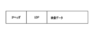
- FIG. 4 is a diagram showing an example of a packet (UDP packet) transmitted by the server according to the embodiment
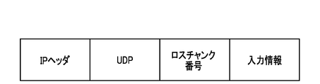
- FIG. 4 is a diagram showing an example of a packet (UDP packet) transmitted by a client terminal according to the embodiment
- FIG. 4 is a sequence diagram showing the flow of processing (at the initial stage) of the communication system according to the embodiment
- 4 is a sequence diagram showing the flow of processing of the communication system according to the embodiment
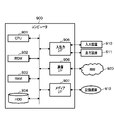
- FIG. 2 is a hardware configuration diagram showing an example of a computer that implements functions of a server and a client terminal according to the present embodiment
- this embodiment a mode for carrying out the present invention (hereinafter referred to as "this embodiment") will be described. First, the outline of the present invention will be explained.
- a communication system receives input information such as line of sight from an HMD from a client (“client-side system 20” in FIG. 1 to be described later) to a network (NW).
- a server in a remote location such as a DC (data center) ("server-side system 10" in FIG. 1, which will be described later) renders the video, and transmits the video data to the client via the NW. This reduces power consumption and computational load on the client side.
- the client may be composed of, for example, a dedicated terminal such as an HMD, or may be composed of a system including a dedicated terminal such as an HMD and a PC connected to the dedicated terminal.
- this communication system uses uncompressed video data for NW communication. Specifically, the video data is chopped (chunked) for each frame according to MTU (Maximum Transmission Unit), which is the maximum data size that can be transmitted in one time on the NW. This fragmented data block is called a chunk, and in this communication system, chunk loss and delay are suppressed by controlling the transmission interval of this chunk according to the chunk loss rate of video data.
- MTU Maximum Transmission Unit
- FIG. 1 is a diagram showing the overall configuration of a communication system 1 according to this embodiment.
- a communication system 1 according to this embodiment includes a server-side system 10 and a client-side system 20, which are connected for communication via a NW.
- the client-side system 20 may be composed only of a dedicated terminal such as an HMD, as described above, or may be composed of a system including a dedicated terminal such as an HMD and a PC connected to the dedicated terminal. However, the client terminal 20 as a dedicated terminal will be described below.
- the client terminal 20 acquires video data 400, which is the result of rendering processing performed on the server side, by transmitting input information 300, such as line of sight from the HMD, to the server 10 via the NW. It has a function of displaying on a display device.
- the server-side system 10 is composed of one or more servers in a DC (data center).
- each functional unit in the control unit 11 to be described later may be provided in a separate server and configured as a system composed of a plurality of servers. A description will be given assuming that the part is provided.
- This server 10 acquires input information 300 such as line of sight from a client-side system (client terminal) 20, performs image rendering processing according to the input information 300 to generate image data, and renders image data to the client via the NW. It transmits to the side system (client terminal) 20 . At this time, the server 10 chunks the video data 400 , controls (determines) the packet transmission interval, and transmits the data to the client-side system (client terminal) 20 .
- the communication system 1 can reduce the power consumption and calculation load of the client-side system (client terminal) 20 by performing rendering processing and the like in the server-side system (server) 10 .
- the communication system 1 controls the transmission interval of packets to which the chunked video data 400 is attached, thereby preventing packets caused by burst traffic generated due to the large data size when video data is transmitted without compression. It is possible to avoid losses, NW delays, and throughput degradation.
- a server-side system (server) 10 and a client-side system (client terminal) 20, which constitute the communication system 1, will be specifically described below.
- a server 10 according to the present embodiment will be described with reference to FIG.
- the server 10 acquires input information 300 such as line of sight from the client terminal 20 , performs image rendering processing according to the input information 300 , and generates image data 400 . Then, the server 10 chunks the generated video data 400 , determines the packet transmission interval based on a predetermined logic regarding the chunk loss rate, and transmits the chunks to the client terminal 20 .
- This server 10 includes a control unit 11 , an input/output unit 12 and a storage unit 13 .
- the input/output unit 12 inputs and outputs information to and from the client terminal 20 and other devices. For example, the input/output unit 12 receives a packet to which the input information 300 is attached from the client terminal 20 and transmits a packet to which the chunked video data 400 is attached. The input/output unit 12 performs input/output of information between a communication interface that transmits and receives information via a communication line (NW) and an input device such as a keyboard (not shown) and an output device such as a monitor (not shown). interface.
- NW communication line
- the storage unit 13 is configured by a hard disk, flash memory, RAM (Random Access Memory), or the like.
- Image data DB (DataBase) 100 and transmission interval chunk loss correspondence information 200 are stored in this storage unit 13 .
- the image data DB 100 stores image data that is used as a material for images to be displayed on the display.
- the transmission interval chunk loss correspondence information 200 is information indicating the chunk loss rate associated with each transmission interval of packets to which the chunked video data 400 is attached, and the details will be described later with reference to FIG.
- the storage unit 13 also temporarily stores a program for executing each function unit of the control unit 11 and information necessary for processing of the control unit 11 .
- the control unit 11 controls overall processing executed by the server 10, and includes an information receiving unit 111, a video processing unit 112, a chunking function unit 113, a chunk loss determination unit 114, and a transmission control unit 115. Configured.
- the information receiving unit 111 receives a packet to which input information 300 for rendering is attached (hereinafter referred to as an “input information packet”) from the client terminal 20 .
- the information included in this input information packet may be only the input information 300 or may be accompanied by the chunk number of the lost chunk (hereinafter referred to as "lost chunk number") together with the input information 300 (details later).
- the input information packet contains only the input information 300 and no loss chunk number is attached, it means that there was no packet loss at the initial stage.
- the information receiving section 111 outputs the input information 300 attached to the received input information packet to the video processing section 112 . Also, information receiving section 111 outputs the information to chunk loss determination section 114 when a loss chunk number is attached to this input information packet.
- the video processing unit 112 Based on the input information 300 received by the information receiving unit 111 , the video processing unit 112 refers to the image data DB 100 in the storage unit 13 and performs video rendering processing according to the input information 300 to generate video data 400 . The video processing unit 112 then outputs the generated video data 400 to the chunking function unit 113 .
- the chunking function unit 113 performs chunking processing on the video data 400 acquired from the video processing unit 112 according to the size of the MTU. Note that the number of frames per second (for example, 60 fps) of the video data 400 is determined by a preset FPS (Frames per Second). become Then, the chunking function unit 113 assigns a chunk number to each chunk of data after chunking. The chunk numbers are assigned with a preset regularity so that the original video data 400 can be restored by arranging them in numerical order.
- FPS Fres per Second
- the chunk loss determining unit 114 determines the chunk loss rate based on the lost chunk number obtained from the information receiving unit 111 and the number of packets counted by the transmission control unit 115 when transmitting the chunked video data 400 to the client terminal 20. calculate. Specifically, the chunk loss determining unit 114 calculates the chunk loss rate by dividing the total number of lost chunks indicated by the lost chunk number by the number of packets counted at the time of transmission. Then, the chunk loss determination unit 114 associates the calculated chunk loss rate with the transmission interval of the packets when the packets transmitted by the transmission control unit 115 are counted, and stores the calculated chunk loss ratio in the transmission interval chunk loss correspondence information in the storage unit 13. 200 (FIG. 2).
- the chunk loss determining unit 114 determines the packet transmission interval for transmitting the chunked video data 400 using a predetermined logic based on the calculated chunk loss rate (hereinafter referred to as "transmission interval determination logic"). do.
- the maximum allowable chunk loss rate is set in advance in the chunk loss determination unit 114 by, for example, the administrator of the communication system 1 when determining the transmission interval based on the transmission interval determination logic.
- the chunk loss determination unit 114 can grasp the congestion occurrence situation in the NW by receiving information (congestion information) indicating the congestion occurrence situation in the NW from a network monitoring device or the like.
- the transmission interval determination logic will be described in detail below.
- the chunk loss determining unit 114 determines the packet transmission interval based on the following [Logic A] during the initial operation of the system and during normal times when congestion does not occur within the NW. Note that the chunk loss determination unit 114 determines that it is a normal time, for example, by not receiving NW congestion information. Also, when determining the packet transmission interval at the initial time (first time), the chunk loss determination unit 114 transmits packets at a preset predetermined initial packet transmission interval.
- the chunk loss determining unit 114 determines the packet transmission interval based on [Logic B] below. Note that the chunk loss determining unit 114 determines that congestion is occurring in the NW, for example, by receiving congestion information from a NW management device or the like. Further, the chunk loss determination unit 114, for example, by receiving congestion information at predetermined time intervals, determines that the congestion state continues, stops receiving congestion information at predetermined time intervals, and If the congestion information is not received until the time elapses, it is determined that the congestion state has been resolved and the normal state has returned. Congestion in the NW may occur, for example, in a server or in a network device such as an L2SW. Also, when congestion occurs, the chunk loss determination unit 114 determines the packet transmission interval by referring to the transmission interval chunk loss correspondence information 200 (FIG. 2).
- FIG. 2 is a diagram showing a data configuration example of the transmission interval chunk loss correspondence information 200 according to this embodiment.
- the chunk loss determination unit 114 stores the chunk loss rate in the transmission interval chunk loss correspondence information 200 in association with the packet transmission interval. For example, when the transmission interval is "100 ( ⁇ s)", the chunk loss rate is "0 (%)”. When the transmission interval is "90 ( ⁇ s)", the chunk loss rate is "5 (%)”.
- the value of this transmission interval chunk loss correspondence information 200 is information updated each time the chunk loss determination unit 114 calculates the chunk loss rate of packets transmitted to the client terminal 20 .
- the chunk loss determination unit 114 sets the transmission interval corresponding to the chunk loss rate of 0, or the transmission interval corresponding to the chunk loss rate closest to 0 if there is no 0. Furthermore, even when packets are transmitted in the longest transmission interval indicated by the transmission interval chunk loss correspondence information 200, if the chunk loss rate (R_LOSS) exceeds the maximum allowable chunk loss rate (MAX_LOSS), the maximum The packet transmission interval may be determined by lengthening the packet transmission interval by a predetermined constant (a3) to the long transmission interval.
- Chunk loss rate (R_LOSS) ⁇ Maximum allowable chunk loss rate (MAX_LOSS)
- the packet transmission interval with the shortest value is set while the chunk loss rate does not exceed the maximum allowable chunk loss rate. For example, if the maximum allowable chunk loss rate is "12 (%)", the current transmission interval is "90 ( ⁇ s)”, and the chunk loss rate is "5 (%)”, the chunk loss rate is The transmission interval is set to “85 ( ⁇ s)” which is “10 (%)”.
- the chunk loss determination unit 114 determines that the congestion in the NW has been resolved due to the stop of receiving the congestion information, etc.
- the transmission interval chunk loss correspondence information 200 (FIG. 2) is updated after the congestion occurs. Correspondence information between the transmission interval and the chunk loss rate is discarded as an outlier. By doing so, the chunk loss determination unit 114 can determine the transmission interval corresponding to the normal time when congestion does not occur.
- the transmission control unit 115 uses the packet transmission interval information determined by the chunk loss determination unit 114 to execute transmission processing of the chunked video data 400 .
- the transmission control unit 115 creates a socket, specifies the destination IP address in the IP header, specifies the UDP port number, and then chunks in the payload part.
- the converted video data 400 is stored, a UDP packet is generated, and the packet is transmitted to the client terminal 20 .
- the transmission control unit 115 stores the packet (UDP packet) transmission interval in the transmission interval chunk loss correspondence information 200 .
- the transmission control unit 115 counts the number of transmitted packets and stores it in the storage unit 13 .
- the transmission interval and the number of packets are used by the chunk loss determination unit 114 to calculate the chunk loss rate and update the transmission interval chunk loss correspondence information 200 .
- the server 10 controls the transmission interval of packets to which the chunked video data 400 is attached, so that the burst traffic caused by the large data size when the video data is transmitted without compression can be prevented. It is possible to avoid packet loss, NW delay, and decrease in throughput. Further, by performing rendering processing and the like in the server 10, the power consumption and calculation load of the client terminal 20 can be reduced.
- a client terminal 20 for example, transmits input information such as the line of sight of the HMD to the server 10, thereby causing the server 10 to execute image rendering processing, which requires a large processing load, and receives the generated image data 400. and displayed on a display device such as a display.
- the client terminal 20 receives the video data 400 from the server 10 as chunked video data 400 and transmits the chunk number of the lost chunk (loss chunk number) to the server 10 .
- the client terminal 20 transmits the loss chunk number by including it in the input information packet that transmits the input information 300 .
- the client terminal 20 may be any terminal other than the HMD as long as it displays video data in real time.
- the client terminal 20 may be a terminal that provides services such as games using moving images.
- the client terminal 20 includes a control section 21 , an input/output section 22 and a storage section 23 .
- the input/output unit 22 inputs and outputs information to and from the server 10 and other devices. For example, the input/output unit 22 transmits an input information packet to which the input information 300 is attached, and receives a packet to which the chunked video data 400 is attached.
- the input/output unit 22 includes a communication interface for transmitting and receiving information via a communication line (NW) and an input/output interface for inputting and outputting information between an output device such as a sensor device and a monitor (not shown). Configured.
- the storage unit 23 is configured by a hard disk, flash memory, RAM, or the like.
- the storage unit 23 temporarily stores a program for executing each function unit of the control unit 21 and information necessary for processing of the control unit 21 .
- the control unit 21 controls overall processing executed by the client terminal 20, and includes an input information acquisition unit 211, a chunk processing unit 212, a data output unit 213, and an input information transmission unit 214.
- the input information acquisition unit 211 receives information (input information 300 for rendering) from various sensors (a gaze tracking sensor, a triaxial acceleration sensor, a gyro sensor, etc.) provided in the client terminal 20, and inputs the input/output unit 22. to get through. Then, the input information acquiring section 211 outputs the acquired input information 300 to the input information transmitting section 214 .
- various sensors a gaze tracking sensor, a triaxial acceleration sensor, a gyro sensor, etc.
- the chunk processing unit 212 receives packets ( FIG. 3 ) to which chunked video data 400 are attached from the server 10 . Then, the chunk processing unit 212 arranges the chunks of each packet in the order of the chunk number, and extracts the chunk number of the lost chunk (loss chunk number). The chunk processing unit 212 outputs the loss chunk number to the input information transmitting unit 214 and also outputs the sorted video data 400 in chunk number order to the data output unit 213 .
- the data output unit 213 decodes (restores) the video using the chunked video data 400 arranged in order of the chunk number, and displays it on a display device such as a display via the input/output unit 22 .
- the input information transmission unit 214 includes the input information 300 acquired from the input information acquisition unit 211 and the loss chunk number acquired from the chunk processing unit 212 in one packet and transmits the packet to the server 10 .
- the input information transmitting unit 214 creates a socket, designates the destination IP address in the IP header, designates the UDP port number, and puts , loss chunk number and input information 300 are stored, a UDP packet is generated, and transmitted to the server 10 .
- the input information transmission unit 214 does not include the loss chunk number during the initial operation when the chunked video data 400 is not received, and when the chunk processing unit 212 does not extract the loss chunk number. Only 300 is included in the UDP packet and transmitted to the server 10 .
- the client terminal 20 can display the video data 400 on a display device such as a display by decoding the chunked video data 400 . Also, the client terminal 20 can suppress the occurrence of delays due to hardware interrupts or the like by including the loss chunk number in a packet of the input information 300 (input information packet) instead of an independent packet.
- 5 and 6 are sequence diagrams showing the flow of processing of the communication system 1 according to this embodiment.
- the input information acquisition unit 211 of the client-side system (client terminal) 20 acquires input information 300 from various sensors and the like (step S1). Subsequently, the input information transmission unit 214 of the client terminal 20 generates a packet (input information packet) with the input information 300 attached, and transmits it to the server-side system (server) 10 (step S2).
- the information receiving unit 111 of the server 10 receives the input information packet, it outputs the input information 300 attached to the packet to the video processing unit 112 (step S3).
- the image processing unit 112 refers to the image data DB 100 in the storage unit 13, performs image rendering processing according to the input information 300, and generates image data 400 (step S4).
- the chunking function unit 113 of the server 10 chunks the generated video data 400 for each frame according to the MTU size (step S5: chunking processing). Then, the chunking function unit 113 assigns a chunk number to each chunk of data after chunking (step S6).
- the chunk loss determination unit 114 determines the initial transmission interval of the chunked video data 400 to be the preset initial packet transmission interval (step S7). Then, the transmission control unit 115 of the server 10 generates a packet including the chunked video data 400 and transmits it to the client terminal 20 at the initial packet transmission interval (step S8). At this time, the transmission control unit 115 counts the transmission interval determined as the initial packet transmission interval and the number of transmitted packets and stores them in the storage unit 13 .
- the chunk processing unit 212 of the client terminal 20 receives the packets (FIG. 3) to which the chunked video data 400 is attached from the server 10, sorts the chunks of each packet in the order of the chunk number, and determines the chunk number of the lost chunk. (loss chunk number) is extracted (step S9). Then, the chunk processing unit 212 outputs the loss chunk number to the input information transmitting unit 214 and also outputs the sorted video data 400 in chunk number order to the data output unit 213 .
- the data output unit 213 of the client terminal 20 decodes (restores) the video using the chunked video data 400 arranged in order of the chunk number, and displays it on a display device such as a display via the input/output unit 22 (step S10).
- the above is the processing of the communication system 1 at the initial time.
- the input information acquisition unit 211 of the client-side system (client terminal) 20 acquires input information 300 from various sensors and the like (step S11).
- the input information transmission unit 214 of the client terminal 20 receives the input information 300 acquired by the input information acquisition unit 211 in step S11 and the loss chunk number extracted by the chunk processing unit 212 in step S9 of FIG.
- a packet (input information packet (FIG. 4)) is generated and transmitted to the server-side system (server) 10 (step S12).
- step S13 when the information receiving unit 111 of the server 10 receives the input information packet, the input information 300 attached to the input information packet is output to the video processing unit 112, and the loss chunk number is sent to the chunk loss determination unit 114. Output (step S13).
- the video processing unit 112 refers to the image data DB 100 in the storage unit 13, performs video rendering processing according to the input information 300, and generates video data 400 (step S14).
- the chunking function unit 113 of the server 10 chunks the generated video data 400 for each frame according to the MTU size (step S15: chunking processing). Then, the chunking function unit 113 assigns a chunk number to each chunk of data after chunking (step S16).
- the chunk loss determination unit 114 of the server 10 calculates the chunk loss rate based on the lost chunk number acquired in step S13 and the number of packets counted by the transmission control unit 115 in step S8 of FIG. 5 (step S17). Subsequently, the chunk loss determination unit 114 associates the calculated chunk loss rate with the transmission interval at the time of transmission of the packet counted by the transmission control unit 115, and stores the transmission interval chunk loss correspondence information in the storage unit 13. 200 (FIG. 2) (step S18).
- the chunk loss determination unit 114 determines packet transmission intervals for transmitting the chunked video data 400 using a predetermined logic (transmission interval determination logic) based on the calculated chunk loss rate (step S19). At this time, the chunk loss determination unit 114 compares the calculated chunk loss rate with the maximum allowable chunk loss rate based on the transmission interval determination logic ([logic A]), and controls increase or decrease of the packet transmission interval. In addition, the chunk loss determination unit 114 determines whether or not congestion has occurred in the NW by whether or not NW congestion information has been received from the NW management device or the like, and if congestion has occurred, The packet transmission interval for transmitting the chunked video data 400 is determined based on the transmission interval determination logic ([Logic B]) adapted to congestion.
- the transmission interval determination logic [Logic B]
- the transmission control unit 115 of the server 10 generates a packet containing the chunked video data 400 in step S15 and transmits it to the client terminal 20 at the packet transmission interval determined in step S19 (step S20). At this time, the transmission control unit 115 counts the transmission interval when the packets are transmitted and the number of transmitted packets and stores them in the storage unit 13 .
- the chunk processing unit 212 of the client terminal 20 receives the packets (FIG. 3) to which the chunked video data 400 is attached from the server 10, sorts the chunks of each packet in order of the chunk number, and extracts the lost chunks. is extracted (step S21). Then, the chunk processing unit 212 outputs the loss chunk number to the input information transmitting unit 214 and also outputs the sorted video data 400 in chunk number order to the data output unit 213 .
- the data output unit 213 of the client terminal 20 decodes (restores) the video using the chunked video data 400 arranged in order of the chunk number, and displays it on a display device such as a display via the input/output unit 22 (step S22). After that, the process from step S11 is repeated.
- FIG. 7 is a hardware configuration diagram showing an example of a computer 900 that implements the functions of the server 10 and the client terminal 20 according to this embodiment.
- the computer 900 includes a CPU (Central Processing Unit) 901, a ROM (Read Only Memory) 902, a RAM 903, a HDD (Hard Disk Drive) 904, an input/output I/F (Interface) 905, a communication I/F 906 and a media I/F 907. have.
- CPU Central Processing Unit
- ROM Read Only Memory
- RAM 903 Random Access Memory
- HDD Hard Disk Drive
- I/F Interface
- the CPU 901 operates based on programs stored in the ROM 902 or HDD 904, and performs control by the control units 11 and 21 (FIG. 1).
- the ROM 902 stores a boot program executed by the CPU 901 when the computer 900 is started, a program related to the hardware of the computer 900, and the like.
- the CPU 901 controls an input device 910 such as a mouse and keyboard, and an output device 911 such as a display and printer via an input/output I/F 905 .
- the CPU 901 acquires data from the input device 910 and outputs the generated data to the output device 911 via the input/output I/F 905 .
- the HDD 904 stores programs executed by the CPU 901 and data used by the programs.
- Communication I/F 906 receives data from other devices via a communication network (for example, NW 920) and outputs the data to CPU 901, and transmits data generated by CPU 901 to other devices via the communication network. .
- the media I/F 907 reads programs or data stored in the recording medium 912 and outputs them to the CPU 901 via the RAM 903 .
- the CPU 901 loads a program related to target processing from the recording medium 912 onto the RAM 903 via the media I/F 907, and executes the loaded program.
- the recording medium 912 is an optical recording medium such as a DVD (Digital Versatile Disc) or a PD (Phase change rewritable Disk), a magneto-optical recording medium such as an MO (Magneto Optical disk), a magnetic recording medium, a semiconductor memory, or the like.
- the CPU 901 of the computer 900 implements the functions of the server 10 and the client terminal 20 by executing programs loaded on the RAM 903 .
- Data in the RAM 903 is stored in the HDD 904 .
- the CPU 901 reads a program related to target processing from the recording medium 912 and executes it.
- the CPU 901 may read a program related to target processing from another device via the communication network (NW 920).
- a communication system is a communication system 1 in which a server-side system 10 and a client-side system 20 are connected for communication via a network.
- an information receiving unit 111 that receives an input information packet containing a lost chunk number, which is the number of a lost chunk in chunked video data, from a client-side system 20;
- a video processing unit 112 that performs rendering processing and generates video data, and a chunking function that chunks the generated video data 400 according to the size of the MTU and assigns a number to each chunk representing the chunked video data 400.
- the chunk loss rate is calculated using the unit 113, the number of packets that have transmitted the chunked video data 400, and the total number of lost chunks indicated by the loss chunk number, and the calculated chunk loss rate and the preset maximum
- a chunk loss determination unit 114 that determines a transmission interval of packets including chunked video data based on a predetermined transmission interval determination logic that determines a transmission interval by comparing with an allowable chunk loss rate, and chunked video.
- a transmission control unit 115 for transmitting each packet containing the data 400 to the client-side system 20 at a determined transmission interval;
- a chunk processing unit 212 that receives each packet including chunked video data 400 from the system 10 and extracts the loss chunk number of the chunk included in the lost packet, and a video using each of the received chunked video data 400.
- a data output unit 213 that decodes and outputs data 400, and an input information transmission unit 214 that transmits an input information packet including the input information 300 and the extracted loss chunk number to the server-side system 10.
- the communication system 1 can reduce the power consumption and calculation load of the client-side system (client terminal) 20 by performing rendering processing and the like in the server-side system (server) 10 .
- the communication system 1 controls the transmission interval of packets to which the chunked video data 400 is attached, so that the video data is transmitted without compression, and packet loss, NW delay, and throughput decrease due to the occurrence of burst traffic. can be avoided. Therefore, the processing load on the client-side system (client terminal) 20 can be reduced, and the need for a high-performance processor or dedicated accelerator on the user side can be eliminated.
- the predetermined transmission interval determination logic lengthens the transmission interval by a predetermined first constant when the calculated chunk loss rate is greater than the maximum allowable chunk loss rate, and calculates the calculated chunk loss The transmission interval is shortened by a predetermined second constant when the rate is less than the maximum allowable chunk loss rate.
- the server-side system (server) 10 of the communication system 1 lengthens the transmission interval when the calculated chunk loss rate is larger than the maximum allowable chunk loss rate by a predetermined transmission interval determination logic, and calculates The transmission interval can be shortened if the chunk loss rate is less than the maximum allowed chunk loss rate. Therefore, the communication system 1 repeats transmission interval determination using a predetermined transmission interval determination logic, thereby determining a more appropriate packet transmission interval within the range of the maximum allowable chunk loss rate or less.
- the transmission control unit 115 stores the transmission interval for transmitting each packet containing the chunked video data 400, and the chunk loss determination unit 114 calculates the chunk loss rate,
- the calculated chunk loss rate is associated with the transmission interval when the chunked video data is transmitted, and stored as transmission interval chunk loss correspondence information 200 in a storage unit. If the calculated chunk loss rate is greater than the maximum allowable chunk loss rate as a predetermined transmission interval determination logic used when congestion information indicating that congestion is occurring in 200, extract the transmission interval corresponding to the chunk loss rate of 0 or, if there is no 0, the transmission interval corresponding to the chunk loss rate closest to 0, and determine the transmission interval of the packet to be transmitted.
- the transmission interval chunk loss correspondence information 200 is referred to, and the calculated chunk loss rate does not exceed the maximum allowable chunk loss rate. It is characterized by extracting short transmission intervals and determining the transmission intervals of packets to be transmitted.
- the server-side system (server) 10 of the communication system 1 can determine the transmission interval of packets to be transmitted by a predetermined transmission interval determination logic when congestion occurs in the network.
- the server-side system (server) 10 refers to the transmission interval chunk loss correspondence information 200 (FIG. 2) when the calculated chunk loss rate is greater than the maximum allowable chunk loss rate, and A transmission interval corresponding to a cross rate of 0, or a transmission interval corresponding to a chunk loss rate closest to 0 if there is no cross rate can be extracted.
- the server-side system (server) 10 refers to the transmission interval chunk loss correspondence information 200, and the calculated chunk loss rate is equal to the maximum allowable
- the shortest transmission interval can be extracted while the cross rate is not exceeded. Therefore, the communication system 1 can determine a more appropriate packet transmission interval when congestion occurs.
- the server according to the present invention is the server 10 connected to the client terminal 20 for communication via a network, and includes the input information 300 for rendering and the number of the lost chunk among the chunked video data.
- an information receiving unit 111 that receives an input information packet including a loss chunk number from the client terminal 20; a video processing unit 112 that performs video rendering processing according to the received input information 300 to generate video data 400;
- the chunking function unit 113 that chunks the obtained video data 400 according to the size of the MTU and gives a number to each chunk representing the chunked video data 400, the number of packets that have transmitted the chunked video data 400, Calculate the chunk loss rate using the total number of lost chunks indicated by the loss chunk number, and determine the transmission interval by comparing the calculated chunk loss rate with a preset maximum allowable chunk loss rate.
- the chunk loss determination unit 114 that determines the transmission interval of the packet containing the chunked video data 400 and each packet containing the chunked video data 400 are transmitted to the client terminal 20 at the determined transmission interval. and a transmission control unit 115 for transmitting to.
- the server 10 by controlling the transmission interval of packets to which the chunked video data 400 is attached, transmits the video data without compression, and reduces packet loss and NW delay due to burst traffic occurrence. , the reduction in throughput can be avoided.
- the client terminal is a client terminal 20 that is connected to the server 10 for communication via a network.
- a chunk processing unit 212 receives each packet including video data 400 and extracts the lost chunk number of the chunk included in the lost packet, and decodes and outputs the video data 400 using each of the received chunked video data 400.
- an input information transmission unit 214 for transmitting to the server 10 an input information packet containing the input information 300 and the extracted loss chunk number.
- the client terminal 20 transmits the loss chunk number in the packet of the input information 300 (input information packet) instead of in an independent packet, thereby suppressing the occurrence of delay due to hardware interrupts or the like.
Landscapes
- Engineering & Computer Science (AREA)
- Multimedia (AREA)
- Signal Processing (AREA)
- Computer Networks & Wireless Communication (AREA)
- Databases & Information Systems (AREA)
- Two-Way Televisions, Distribution Of Moving Picture Or The Like (AREA)
- Data Exchanges In Wide-Area Networks (AREA)
Abstract
Description
本実施形態に係る通信システム(後記する図1参照)は、例えば、HMDにおける視線等の入力情報を、ユーザ宅内にあるクライアント(後記する図1の「クライアント側システム20」)からネットワーク(NW)経由で取得し、DC(データセンタ)等の遠隔地にあるサーバ(後記する図1の「サーバ側システム10」)で映像のレンダリング処理を行い、映像データをNW経由でクライアントに送信する。これにより、クライアント側での電力消費と計算負荷とを低減する。
なお、クライアントは、例えばHMDのような専用端末のみで構成されていてもよいし、HMD等の専用端末とその専用端末に接続されたPCとを備えるシステムで構成されていてもよい。
以下、本発明の通信システムについて説明する。
図1は、本実施形態に係る通信システム1の全体構成を示す図である。
本実施形態に係る通信システム1は、図1に示すように、サーバ側システム10とクライアント側システム20とを備え、NWを介して通信接続される。
このクライアント端末20は、例えばHMDにおける視線等の入力情報300を、サーバ10にNWを介して送信することにより、サーバ側でレンダリング処理を行った結果である映像データ400を取得し、ディスプレイ等の表示装置に表示する機能を有する。
このサーバ10は、クライアント側システム(クライアント端末)20から、視線等の入力情報300を取得し、その入力情報300に応じた映像のレンダリング処理を行って映像データを生成し、NWを介してクライアント側システム(クライアント端末)20へ送信する。その際、サーバ10は、映像データ400をチャンク化し、パケットの送信間隔を制御(決定)した上でクライアント側システム(クライアント端末)20へ送信する。
この通信システム1を構成する、サーバ側システム(サーバ)10およびクライアント側システム(クライアント端末)20について、以下具体的に説明する。
図1を参照して、本実施形態に係るサーバ10について説明する。
サーバ10は、クライアント端末20から、視線等の入力情報300を取得し、その入力情報300に応じた映像のレンダリング処理を行い映像データ400を生成する。そして、サーバ10は、生成した映像データ400をチャンク化し、チャンクロス率に関する所定のロジックに基づき、パケット送信間隔を決定し、クライアント端末20へ送信する。
このサーバ10は、制御部11と、入出力部12と、記憶部13とを備える。
この入出力部12は、通信回線(NW)を介して情報の送受信を行う通信インタフェースと、不図示のキーボード等の入力装置やモニタ等の出力装置との間で情報の入出力を行う入出力インタフェースとから構成される。
この記憶部13には、画像データDB(DataBase)100および送信間隔チャンクロス対応情報200が格納される。
画像データDB100には、例えば、クライアント端末20がHMDの場合、ディスプレイに表示する映像の素材となる画像データが格納される。
送信間隔チャンクロス対応情報200は、チャンク化した映像データ400を付したパケットの送信間隔それぞれに対応付けたチャンクロス率を示す情報であり、詳細は図2を参照して後記する。
この記憶部13には、さらに、制御部11の各機能部を実行させるためのプログラムや、制御部11の処理に必要な情報が一時的に記憶される。
なお、入力情報パケットにおいて、入力情報300のみで、ロスチャンク番号が付されない場合は、初期時とパケットロスがなかった場合である。
情報受信部111は、受信した入力情報パケットに付された入力情報300を、映像処理部112に出力する。また、情報受信部111は、この入力情報パケットにロスチャンク番号が付されていた場合には、その情報をチャンクロス判定部114に出力する。
そして、映像処理部112は、生成した映像データ400を、チャンク化機能部113に出力する。
そして、チャンク化機能部113は、チャンク化後の各チャンクのデータについてチャンク番号の付与を行う。このチャンク番号は、番号順に整列させることで、元の映像データ400が復元できるように予め設定した規則性をもって付される。
そして、チャンクロス判定部114は、送信制御部115が送信したパケットをカウントした際のそのパケットの送信間隔に対応付けて、計算したチャンクロス率を、記憶部13内の送信間隔チャンクロス対応情報200(図2)に格納する。
なお、前提として、チャンクロス判定部114には、送信間隔決定ロジックに基づき送信間隔を決定する際、予め最大許容チャンクロス率が、例えば通信システム1の管理者等により設定される。また、チャンクロス判定部114は、NW内において輻輳の発生状況を示す情報(輻輳情報)を、ネットワーク監視装置等から受信することにより、NW内の輻輳発生状況を把握できる。
以下、送信間隔決定ロジックについて、詳細に説明する。
チャンクロス判定部114は、システム初期稼働時、および、NW内において輻輳が発生していないことを示す通常時の状況においては、以下の[ロジックA]に基づき、パケット送信間隔を決定する。なお、チャンクロス判定部114は、例えばNWの輻輳情報を受信していないことにより、通常時であることを判定する。また、チャンクロス判定部114は、初期時(一度目)のパケット送信間隔の決定の際には、予め設定した所定の初期パケット送信間隔によりパケットを送信する。
・チャンクロス率(R_LOSS) > 最大許容チャンクロス率(MAX_LOSS)
この場合、所定の定数(a1:第1定数)だけ、パケット送信間隔を長くする。
・チャンクロス率(R_LOSS) < 最大許容チャンクロス率(MAX_LOSS)
この場合、所定の定数(a2:第2定数)だけ、パケット送信間隔を短くする。
なお、所定の定数(a1)と(a2)とは、同じ値でもよい。
チャンクロス判定部114は、NW内において輻輳が発生している輻輳発生時においては、以下の[ロジックB]に基づき、パケット送信間隔を決定する。なお、チャンクロス判定部114は、例えば、NWの管理装置等から輻輳情報を受信することにより、NW内に輻輳が発生していると判定する。また、チャンクロス判定部114は、例えば、所定の時間間隔で輻輳情報を受信することにより、輻輳状態が継続していると判定し、所定の時間間隔での輻輳情報の受信が停止し、一定時間経過後までに輻輳情報を受信しなければ、輻輳状態が解消され通常時に戻ったと判定する。なお、NW内における輻輳は、例えば、サーバ内で発生している場合や、L2SW等のネットワーク機器で発生している場合等がある。
また、チャンクロス判定部114は、輻輳発生時においては、送信間隔チャンクロス対応情報200(図2)を参照して、パケット送信間隔を決定する。
図2に示すように、送信間隔チャンクロス対応情報200には、チャンクロス判定部114により、パケットの送信間隔に対応付けて、チャンクロス率が格納される。
例えば、送信間隔が「100(μs)」のとき、チャンクロス率は「0(%)」である。送信間隔が「90(μs)」のとき、チャンクロス率は「5(%)」である。
この送信間隔チャンクロス対応情報200の値は、クライアント端末20へ送信されたパケットのチャンクロス率を、チャンクロス判定部114が計算する度に更新される情報である。
・(輻輳発生時)チャンクロス率(R_LOSS) > 最大許容チャンクロス率(MAX_LOSS)
この場合、送信間隔チャンクロス対応情報200(図2)において、チャンクロス率が「0」に対応する送信間隔を、パケット送信間隔に設定する。例えば、最大許容チャンクロス率が「8(%)」であり、現時点での送信間隔が「80(μs)」、チャンクロス率が「15(%)」であった場合に、チャンクロス率が「0(%)」である送信間隔「95(μs)」に設定する。
なお、チャンクロス率が「0(%)」に対応する送信間隔が複数存在する場合には、送信間隔が最も短いものや、送信間隔が最も長いもの、ランダムに決定する等のようないずれかを設定しておく。
また、チャンクロス率が「0(%)」に対応する送信間隔が、送信間隔チャンクロス対応情報200にその時点で存在していない場合には、その時点で存在するチャンクロス率「0(%)」に一番近い送信間隔の値に設定する。つまり、チャンクロス判定部114は、チャンクロス率が0に対応する送信間隔、若しくは、0がない場合には最も0に近いチャンクロス率に対応する送信間隔に設定する。
さらに、送信間隔チャンクロス対応情報200で示される、最も長い送信間隔において、パケットを送信した場合においても、チャンクロス率(R_LOSS)が最大許容チャンクロス率(MAX_LOSS)を超える場合には、その最も長い送信間隔に、所定の定数(a3)だけパケット送信間隔を長くして、パケット送信間隔を決定するようにしてもよい。
この場合、送信間隔チャンクロス対応情報200(図2)において、チャンクロス率が最大許容チャンクロス率を超えない中で、最も送信間隔が短い値のパケット送信間隔を設定する。例えば、最大許容チャンクロス率が「12(%)」であり、現時点での送信間隔が「90(μs)」、チャンクロス率が「5(%)」であった場合に、チャンクロス率が「10(%)」である送信間隔「85(μs)」に設定する。
このようにすることにより、輻輳が発生していない通常時に対応した送信間隔をチャンクロス判定部114が決定することができる。
具体的には、送信制御部115は、図3のUDPパケットの例で示すように、ソケットを作り、IPヘッダに宛先IPアドレスを指定し、UDPポート番号を指定した上で、ペイロード部分にチャンク化した映像データ400を格納してUDPパケットを生成し、クライアント端末20へ送信する。
このパケット送信時において、送信制御部115は、パケット(UDPパケット)の送信間隔を、送信間隔チャンクロス対応情報200に記憶する。そして、送信制御部115は、送信したパケット数をカウントし記憶部13に記憶しておく。この送信間隔とパケット数とは、チャンクロス判定部114による、チャンクロス率の計算、および、送信間隔チャンクロス対応情報200の更新に利用される。
図1を参照して、本実施形態に係るクライアント端末20について説明する。
クライアント端末20は、例えば、HMDにおける視線等の入力情報を、サーバ10へ送信することにより、サーバ10において、処理負荷の大きい、映像のレンダリング処理等を実行させ、生成された映像データ400を受信してディスプレイ等の表示装置に表示する。このクライアント端末20は、サーバ10からの映像データ400を、チャンク化した映像データ400として受信し、ロスしたチャンクのチャンク番号(ロスチャンク番号)を、サーバ10へ送信する。クライアント端末20は、このロスチャンク番号の送信を、入力情報300を送信する入力情報パケットに含めて送信する。これにより、ロスチャンク番号を独立した別パケットにより送信する場合に比べ、ハードウェア割り込みにおいて、複数のパケット同士の競合により待ち合わせが発生し、msオーダの遅延が発生することを抑えることができる。なお、クライアント端末20は、HMD以外でも、リアルタイムに映像データを表示する端末であればよく、例えば、動画映像を利用するゲーム等のサービスを提供する端末でもよい。
このクライアント端末20は、制御部21と、入出力部22と、記憶部23とを備える。
この入出力部22は、通信回線(NW)を介して情報の送受信を行う通信インタフェースと、不図示のセンサ装置やモニタ等の出力装置との間で情報の入出力を行う入出力インタフェースとから構成される。
この記憶部23には、制御部21の各機能部を実行させるためのプログラムや、制御部21の処理に必要な情報が一時的に記憶される。
チャンク処理部212は、ロスチャンク番号を入力情報送信部214に出力するとともに、整列させたチャンク番号順の映像データ400を、データ出力部213に出力する。
具体的には、入力情報送信部214は、図4のUDPパケットの例で示すように、ソケットを作り、IPヘッダに宛先IPアドレスを指定し、UDPポート番号を指定した上で、ペイロード部分に、ロスチャンク番号および入力情報300を格納して、UDPパケットを生成し、サーバ10へ送信する。
また、クライアント端末20は、ロスチャンク番号を、独立したパケットではなく、入力情報300のパケット(入力情報パケット)に含めて送信することにより、ハードウェア割り込み等による遅延の発生を抑えることができる。
次に、通信システム1が実行する処理について説明する。
図5および図6は、本実施形態に係る通信システム1の処理の流れを示すシーケンス図である。
続いて、クライアント端末20の入力情報送信部214が、その入力情報300を付したパケット(入力情報パケット)を生成し、サーバ側システム(サーバ)10へ送信する(ステップS2)。
そして、映像処理部112は、記憶部13内の画像データDB100を参照し、入力情報300に応じた映像のレンダリング処理を行い映像データ400を生成する(ステップS4)。
そして、チャンク化機能部113は、チャンク化後の各チャンクのデータについてチャンク番号の付与を行う(ステップS6)。
そして、サーバ10の送信制御部115は、チャンク化した映像データ400を含むパケットを生成し、初期パケット送信間隔でクライアント端末20へ送信する(ステップS8)。このとき、送信制御部115は、初期パケット送信間隔として決定した送信間隔、および、送信したパケット数をカウントして記憶部13に記憶しておく。
そして、チャンク処理部212は、ロスチャンク番号を入力情報送信部214に出力するとともに、整列させたチャンク番号順の映像データ400を、データ出力部213に出力する。
ここまでが、初期時の通信システム1の処理である。
そして、チャンク化機能部113は、チャンク化後の各チャンクのデータについてチャンク番号の付与を行う(ステップS16)。
続いて、チャンクロス判定部114は、送信制御部115がカウントした際のそのパケットの送信時における送信間隔に対応付けて、計算したチャンクロス率を、記憶部13内の送信間隔チャンクロス対応情報200(図2)に格納する(ステップS18)。
このとき、チャンクロス判定部114は、送信間隔決定ロジック([ロジックA])に基づき、計算したチャンクロス率と、最大許容チャンクロス率とを比較して、パケット送信間隔の増減を制御する。また、チャンクロス判定部114が、NW管理装置等からNWの輻輳情報を受信しているか否かにより、NWに輻輳が発生しているか否を判定し、輻輳が発生している場合には、輻輳時に適応する送信間隔決定ロジック([ロジックB])に基づき、チャンク化した映像データ400を送信するパケット送信間隔を決定する。
そして、チャンク処理部212は、ロスチャンク番号を入力情報送信部214に出力するとともに、整列させたチャンク番号順の映像データ400を、データ出力部213に出力する。
これ以降は、ステップS11からの処理が繰り返される。
本実施形態に係るサーバ10およびクライアント端末20は、例えば図7に示すような構成のコンピュータ900によって実現される。
図7は、本実施形態に係るサーバ10およびクライアント端末20の機能を実現するコンピュータ900の一例を示すハードウェア構成図である。コンピュータ900は、CPU(Central Processing Unit)901、ROM(Read Only Memory)902、RAM903、HDD(Hard Disk Drive)904、入出力I/F(Interface)905、通信I/F906およびメディアI/F907を有する。
以下、本発明に係る通信システム等の効果について説明する。
本発明に係る通信システムは、サーバ側システム10と、クライアント側システム20とがネットワークを介して通信接続される通信システム1であって、サーバ側システム10が、レンダリングを行うための入力情報300と、チャンク化された映像データのうち、ロスしたチャンクの番号であるロスチャンク番号とを含む入力情報パケットを、クライアント側システム20から受信する情報受信部111と、受信した入力情報300に応じた映像のレンダリング処理を行い、映像データを生成する映像処理部112と、生成した映像データ400を、MTUのサイズに合わせてチャンク化し、チャンク化した映像データ400を示すチャンクそれぞれに番号を付与するチャンク化機能部113と、チャンク化した映像データ400を送信したパケット数と、ロスチャンク番号で示されるロスしたチャンクの合計数とを用いてチャンクロス率を計算し、計算したチャンクロス率と、予め設定した最大許容チャンクロス率とを比較することにより送信間隔を決定する、所定の送信間隔決定ロジックに基づき、チャンク化した映像データを含むパケットの送信間隔を決定するチャンクロス判定部114と、チャンク化した映像データ400を含むパケットそれぞれを、決定した送信間隔によりクライアント側システム20に送信する送信制御部115と、を備え、クライアント側システム20が、入力情報300を取得する入力情報取得部211と、サーバ側システム10から、チャンク化した映像データ400を含むパケットそれぞれを受信し、ロスしたパケットに含まれるチャンクのロスチャンク番号を抽出するチャンク処理部212と、受信したチャンク化した映像データ400それぞれを用いて映像データ400をデコードして出力するデータ出力部213と、入力情報300、および、抽出したロスチャンク番号を含む入力情報パケットを、サーバ側システム10に送信する入力情報送信部214と、を備えることを特徴とする。
よって、クライアント側システム(クライアント端末)20の処理負荷を低減し、ユーザ側において、高性能のプロセッサや専用のアクセラレータを備える必要をなくすことができる。
よって、通信システム1は、所定の送信間隔決定ロジックを用いた送信間隔の決定を繰り返すことにより、最大許容チャンクロス率以下に収まる範囲で、より適切なパケットの送信間隔を決定することができる。
この送信間隔決定ロジックにより、サーバ側システム(サーバ)10は、計算したチャンクロス率が、最大許容チャンクロス率よりも大きいときに、送信間隔チャンクロス対応情報200(図2)を参照し、チャンクロス率が0に対応する送信間隔、若しくは、0がない場合には最も0に近いチャンクロス率に対応する送信間隔を抽出できる。また、サーバ側システム(サーバ)10は、計算したチャンクロス率が、最大許容チャンクロス率未満である場合に、送信間隔チャンクロス対応情報200を参照し、計算したチャンクロス率が、最大許容チャンクロス率を超えない中で、最も送信間隔が短い送信間隔を抽出できる。
よって、通信システム1は、輻輳発生時において、より適切なパケットの送信間隔を決定することができる。
10 サーバ側システム(サーバ)
11,21 制御部
12,22 入出力部
13,23 記憶部
20 クライアント側システム(クライアント端末)
100 画像データDB
111 情報受信部
112 映像処理部
113 チャンク化機能部
114 チャンクロス判定部
115 送信制御部
200 送信間隔チャンクロス対応情報
211 入力情報取得部
212 チャンク処理部
213 データ出力部
214 入力情報送信部
300 入力情報
400 映像データ
Claims (8)
- サーバ側システムと、クライアント側システムとがネットワークを介して通信接続される通信システムであって、
前記サーバ側システムは、
レンダリングを行うための入力情報と、チャンク化された映像データのうち、ロスしたチャンクの番号であるロスチャンク番号とを含む入力情報パケットを、前記クライアント側システムから受信する情報受信部と、
受信した前記入力情報に応じた映像のレンダリング処理を行い、映像データを生成する映像処理部と、
生成した前記映像データを、MTU(Maximum Transmission Unit)のサイズに合わせてチャンク化し、チャンク化した映像データを示すチャンクそれぞれに番号を付与するチャンク化機能部と、
前記チャンク化した映像データを送信したパケット数と、前記ロスチャンク番号で示されるロスしたチャンクの合計数とを用いてチャンクロス率を計算し、計算した前記チャンクロス率と、予め設定した最大許容チャンクロス率とを比較することにより送信間隔を決定する、所定の送信間隔決定ロジックに基づき、前記チャンク化した映像データを含むパケットの送信間隔を決定するチャンクロス判定部と、
前記チャンク化した映像データを含むパケットそれぞれを、決定した前記送信間隔により前記クライアント側システムに送信する送信制御部と、を備え、
前記クライアント側システムは、
前記入力情報を取得する入力情報取得部と、
前記サーバ側システムから、前記チャンク化した映像データを含むパケットそれぞれを受信し、ロスしたパケットに含まれるチャンクの前記ロスチャンク番号を抽出するチャンク処理部と、
受信した前記チャンク化した映像データそれぞれを用いて映像データをデコードして出力するデータ出力部と、
前記入力情報、および、抽出した前記ロスチャンク番号を含む前記入力情報パケットを、前記サーバ側システムに送信する入力情報送信部と、を備えること
を特徴とする通信システム。 - 前記所定の送信間隔決定ロジックは、
計算した前記チャンクロス率が、前記最大許容チャンクロス率よりも大きい場合に、所定の第1定数だけ、前記送信間隔を長くし、
計算した前記チャンクロス率が、前記最大許容チャンクロス率未満である場合に、所定の第2定数だけ、前記送信間隔を短くすること
を特徴とする請求項1に記載の通信システム。 - 前記送信制御部は、前記チャンク化した映像データを含むパケットそれぞれを送信する送信間隔を記憶しておき、
前記チャンクロス判定部は、前記チャンクロス率を計算した際に、計算した前記チャンクロス率と、そのチャンク化した映像データを送信したときの送信間隔とを対応付けて送信間隔チャンクロス対応情報として記憶部に記憶しておき、
前記チャンクロス判定部は、前記ネットワーク内に輻輳が発生していることを示す輻輳情報を受信した場合に用いる前記所定の送信間隔決定ロジックとして、
計算した前記チャンクロス率が、前記最大許容チャンクロス率よりも大きい場合に、前記送信間隔チャンクロス対応情報を参照し、前記チャンクロス率が0に対応する送信間隔、若しくは、0がない場合には最も0に近いチャンクロス率に対応する送信間隔を抽出して、送信する前記パケットの送信間隔を決定し、
計算した前記チャンクロス率が、前記最大許容チャンクロス率未満である場合に、前記送信間隔チャンクロス対応情報を参照し、計算した前記チャンクロス率が、前記最大許容チャンクロス率を超えない中で、最も送信間隔が短い送信間隔を抽出して、送信する前記パケットの送信間隔を決定すること
を特徴とする請求項1に記載の通信システム。 - サーバ側システムと、クライアント側システムとがネットワークを介して通信接続される通信システムの通信方法であって、
前記サーバ側システムは、
レンダリングを行うための入力情報と、チャンク化された映像データのうち、ロスしたチャンクの番号であるロスチャンク番号とを含む入力情報パケットを、前記クライアント側システムから受信するステップと、
受信した前記入力情報に応じた映像のレンダリング処理を行い、映像データを生成するステップと、
生成した前記映像データを、MTUのサイズに合わせてチャンク化し、チャンク化した映像データを示すチャンクそれぞれに番号を付与するステップと、
前記チャンク化した映像データを送信したパケット数と、前記ロスチャンク番号で示されるロスしたチャンクの合計数とを用いてチャンクロス率を計算し、計算した前記チャンクロス率と、予め設定した最大許容チャンクロス率とを比較することにより送信間隔を決定する、所定の送信間隔決定ロジックに基づき、前記チャンク化した映像データを含むパケットの送信間隔を決定するステップと、
前記チャンク化した映像データを含むパケットそれぞれを、決定した前記送信間隔により前記クライアント側システムに送信するステップと、を実行し、
前記クライアント側システムは、
前記入力情報を取得するステップと、
前記サーバ側システムから、前記チャンク化した映像データを含むパケットそれぞれを受信し、ロスしたパケットに含まれるチャンクの前記ロスチャンク番号を抽出するステップと、
受信した前記チャンク化した映像データそれぞれを用いて映像データをデコードして出力するステップと、
前記入力情報、および、抽出した前記ロスチャンク番号を含む前記入力情報パケットを、前記サーバ側システムに送信するステップと、を実行すること
を特徴とする通信方法。 - クライアント端末にネットワークを介して通信接続するサーバであって、
レンダリングを行うための入力情報と、チャンク化された映像データのうち、ロスしたチャンクの番号であるロスチャンク番号とを含む入力情報パケットを、前記クライアント端末から受信する情報受信部と、
受信した前記入力情報に応じた映像のレンダリング処理を行い、映像データを生成する映像処理部と、
生成した前記映像データを、MTUのサイズに合わせてチャンク化し、チャンク化した映像データを示すチャンクそれぞれに番号を付与するチャンク化機能部と、
前記チャンク化した映像データを送信したパケット数と、前記ロスチャンク番号で示されるロスしたチャンクの合計数とを用いてチャンクロス率を計算し、計算した前記チャンクロス率と、予め設定した最大許容チャンクロス率とを比較することにより送信間隔を決定する、所定の送信間隔決定ロジックに基づき、前記チャンク化した映像データを含むパケットの送信間隔を決定するチャンクロス判定部と、
前記チャンク化した映像データを含むパケットそれぞれを、決定した前記送信間隔により前記クライアント端末に送信する送信制御部と、
を備えることを特徴とするサーバ。 - コンピュータを、請求項5に記載のサーバとして機能させるためのプログラム。
- サーバにネットワークを介して通信接続するクライアント端末であって、
レンダリングを行うための入力情報を取得する入力情報取得部と、
前記サーバから、チャンク化した映像データを含むパケットそれぞれを受信し、ロスしたパケットに含まれるチャンクのロスチャンク番号を抽出するチャンク処理部と、
受信した前記チャンク化した映像データそれぞれを用いて映像データをデコードして出力するデータ出力部と、
前記入力情報、および、抽出した前記ロスチャンク番号を含む入力情報パケットを、前記サーバに送信する入力情報送信部と、
を備えることを特徴とするクライアント端末。 - コンピュータを、請求項7に記載のクライアント端末として機能させるためのプログラム。
Priority Applications (3)
| Application Number | Priority Date | Filing Date | Title |
|---|---|---|---|
| PCT/JP2021/011614 WO2022201221A1 (ja) | 2021-03-22 | 2021-03-22 | 通信システム、通信方法、サーバ、クライアント端末、および、プログラム |
| US18/283,409 US12363362B2 (en) | 2021-03-22 | 2021-03-22 | Communication system, communication method, server, client terminal, and program |
| JP2023508146A JP7452753B2 (ja) | 2021-03-22 | 2021-03-22 | 通信システム、通信方法、サーバ、クライアント端末、および、プログラム |
Applications Claiming Priority (1)
| Application Number | Priority Date | Filing Date | Title |
|---|---|---|---|
| PCT/JP2021/011614 WO2022201221A1 (ja) | 2021-03-22 | 2021-03-22 | 通信システム、通信方法、サーバ、クライアント端末、および、プログラム |
Publications (1)
| Publication Number | Publication Date |
|---|---|
| WO2022201221A1 true WO2022201221A1 (ja) | 2022-09-29 |
Family
ID=83395365
Family Applications (1)
| Application Number | Title | Priority Date | Filing Date |
|---|---|---|---|
| PCT/JP2021/011614 Ceased WO2022201221A1 (ja) | 2021-03-22 | 2021-03-22 | 通信システム、通信方法、サーバ、クライアント端末、および、プログラム |
Country Status (3)
| Country | Link |
|---|---|
| US (1) | US12363362B2 (ja) |
| JP (1) | JP7452753B2 (ja) |
| WO (1) | WO2022201221A1 (ja) |
Citations (4)
| Publication number | Priority date | Publication date | Assignee | Title |
|---|---|---|---|---|
| JP2013025668A (ja) * | 2011-07-25 | 2013-02-04 | Nippon Hoso Kyokai <Nhk> | 管理装置、素材処理装置、完成ファイル生成装置、素材蓄積装置及びそのプログラム、並びに、並列処理システム |
| US20150261600A1 (en) * | 2014-03-14 | 2015-09-17 | Cisco Technology, Inc. | Reconciling redundant copies of media content |
| JP2015228568A (ja) * | 2014-05-30 | 2015-12-17 | 日本電信電話株式会社 | 映像品質推定装置及び方法及びプログラム |
| JP2017157913A (ja) * | 2016-02-29 | 2017-09-07 | Kddi株式会社 | 推定装置、推定方法及び推定プログラム |
Family Cites Families (8)
| Publication number | Priority date | Publication date | Assignee | Title |
|---|---|---|---|---|
| CN102468941B (zh) * | 2010-11-18 | 2014-07-30 | 华为技术有限公司 | 网络丢包处理方法及装置 |
| EP2932667A4 (en) * | 2012-10-03 | 2016-09-28 | Distrix Networks Ltd | SYSTEMS AND METHODS FOR ADAPTIVE LOAD BALANCING COMMUNICATIONS, ROUTING, FILTERING AND ACCESS CONTROL IN DISTRIBUTED NETWORKS |
| US9530451B2 (en) * | 2013-11-27 | 2016-12-27 | Adobe Systems Incorporated | Reducing network bandwidth usage in a distributed video editing system |
| EP3127333A1 (en) * | 2014-03-31 | 2017-02-08 | British Telecommunications Public Limited Company | Multicast streaming |
| US20160323062A1 (en) * | 2015-05-01 | 2016-11-03 | Ubitus Inc. | Packet recovery in interactive real-time media protocol |
| JP6436926B2 (ja) | 2016-03-03 | 2018-12-12 | ソフトバンク株式会社 | 通信装置、通信システム、プログラム、及び通信方法 |
| JP6949801B2 (ja) | 2018-10-17 | 2021-10-13 | 株式会社日立製作所 | ストレージシステム及びストレージシステムにおけるデータ配置方法 |
| WO2022098377A1 (en) * | 2020-12-17 | 2022-05-12 | Futurewei Technologies, Inc. | Qualitative communication using adaptive network coding with a sliding window |
-
2021
- 2021-03-22 WO PCT/JP2021/011614 patent/WO2022201221A1/ja not_active Ceased
- 2021-03-22 JP JP2023508146A patent/JP7452753B2/ja active Active
- 2021-03-22 US US18/283,409 patent/US12363362B2/en active Active
Patent Citations (4)
| Publication number | Priority date | Publication date | Assignee | Title |
|---|---|---|---|---|
| JP2013025668A (ja) * | 2011-07-25 | 2013-02-04 | Nippon Hoso Kyokai <Nhk> | 管理装置、素材処理装置、完成ファイル生成装置、素材蓄積装置及びそのプログラム、並びに、並列処理システム |
| US20150261600A1 (en) * | 2014-03-14 | 2015-09-17 | Cisco Technology, Inc. | Reconciling redundant copies of media content |
| JP2015228568A (ja) * | 2014-05-30 | 2015-12-17 | 日本電信電話株式会社 | 映像品質推定装置及び方法及びプログラム |
| JP2017157913A (ja) * | 2016-02-29 | 2017-09-07 | Kddi株式会社 | 推定装置、推定方法及び推定プログラム |
Also Published As
| Publication number | Publication date |
|---|---|
| US20240098318A1 (en) | 2024-03-21 |
| JP7452753B2 (ja) | 2024-03-19 |
| US12363362B2 (en) | 2025-07-15 |
| JPWO2022201221A1 (ja) | 2022-09-29 |
Similar Documents
| Publication | Publication Date | Title |
|---|---|---|
| US9727373B2 (en) | Providing resumption data in a distributed processing system | |
| US9344735B2 (en) | Progressive shape based encoding of video content within a swarm environment | |
| US20170180272A1 (en) | System and method for accelerating network applications using an enhanced network interface and massively parallel distributed processing | |
| CN111010582A (zh) | 一种云桌面图像处理方法、装置、设备及可读存储介质 | |
| US12301955B2 (en) | Systems and methods for efficient management of resources for streaming interactive multimedia content | |
| EP3410302B1 (en) | Graphic instruction data processing method, apparatus | |
| US12179095B2 (en) | Systems and methods for efficient management of resources for streaming interactive multimedia content | |
| WO2016044329A1 (en) | Real-time, low memory estimation of unique client computers communicating with a server computer | |
| CN113490055A (zh) | 数据处理方法和装置 | |
| US9852520B2 (en) | Implementing reduced video stream bandwidth requirements when remotely rendering complex computer graphics scene | |
| US12094435B2 (en) | Systems and methods for managing application refresh rates presented on a display | |
| CN107872471B (zh) | 远程桌面图像指令处理方法和系统 | |
| KR20230029502A (ko) | 에지 컴퓨팅 네트워크, 데이터 전송 방법, 장치, 기기 및 기록 매체 | |
| KR20080049710A (ko) | 임의 포맷의 대형 객체의 통신을 지원하기 위한 원격프로토콜 | |
| US9413789B2 (en) | Method and system for managing high-bandwidth data sharing | |
| JP7452753B2 (ja) | 通信システム、通信方法、サーバ、クライアント端末、および、プログラム | |
| Paul et al. | Chromium renderserver: Scalable and open remote rendering infrastructure | |
| WO2024109810A1 (zh) | 虚拟桌面性能探测方法、装置、设备及存储介质和程序 | |
| KR101758065B1 (ko) | 부하분산 시스템, 그 제어방법 및 이를 수행하기 위한 기록매체 | |
| CA2859577A1 (en) | Image processing apparatus, method of controlling the same, program and storage medium | |
| JP7521677B2 (ja) | ガードタイム計算装置、ガードタイム計算方法、及びプログラム | |
| WO2023218614A1 (ja) | 配信装置、配信方法及びプログラム | |
| US20250330553A1 (en) | System and method for frame rate control and priority frame processing for 3d rendering | |
| CN114071185B (zh) | 视频流下发的方法、相关装置及计算机程序产品 | |
| EP4507798A1 (en) | Systems and methods for efficient management of resources for streaming interactive multimedia content |
Legal Events
| Date | Code | Title | Description |
|---|---|---|---|
| 121 | Ep: the epo has been informed by wipo that ep was designated in this application |
Ref document number: 21932838 Country of ref document: EP Kind code of ref document: A1 |
|
| WWE | Wipo information: entry into national phase |
Ref document number: 2023508146 Country of ref document: JP |
|
| WWE | Wipo information: entry into national phase |
Ref document number: 18283409 Country of ref document: US |
|
| NENP | Non-entry into the national phase |
Ref country code: DE |
|
| 122 | Ep: pct application non-entry in european phase |
Ref document number: 21932838 Country of ref document: EP Kind code of ref document: A1 |
|
| WWG | Wipo information: grant in national office |
Ref document number: 18283409 Country of ref document: US |