WO2022196832A1 - ロボット装置、傾き調整装置 - Google Patents
ロボット装置、傾き調整装置 Download PDFInfo
- Publication number
- WO2022196832A1 WO2022196832A1 PCT/JP2022/012912 JP2022012912W WO2022196832A1 WO 2022196832 A1 WO2022196832 A1 WO 2022196832A1 JP 2022012912 W JP2022012912 W JP 2022012912W WO 2022196832 A1 WO2022196832 A1 WO 2022196832A1
- Authority
- WO
- WIPO (PCT)
- Prior art keywords
- robot
- spherical plain
- tilt
- plain bearing
- adjusting device
- Prior art date
- Legal status (The legal status is an assumption and is not a legal conclusion. Google has not performed a legal analysis and makes no representation as to the accuracy of the status listed.)
- Ceased
Links
Images











Classifications
-
- A—HUMAN NECESSITIES
- A61—MEDICAL OR VETERINARY SCIENCE; HYGIENE
- A61G—TRANSPORT, PERSONAL CONVEYANCES OR ACCOMMODATION SPECIALLY ADAPTED FOR PATIENTS OR DISABLED PERSONS; OPERATING TABLES OR CHAIRS; CHAIRS FOR DENTISTRY; FUNERAL DEVICES
- A61G13/00—Operating tables; Auxiliary appliances therefor
- A61G13/02—Adjustable operating tables; Controls therefor
- A61G13/04—Adjustable operating tables; Controls therefor tiltable around transverse or longitudinal axis
-
- A—HUMAN NECESSITIES
- A61—MEDICAL OR VETERINARY SCIENCE; HYGIENE
- A61G—TRANSPORT, PERSONAL CONVEYANCES OR ACCOMMODATION SPECIALLY ADAPTED FOR PATIENTS OR DISABLED PERSONS; OPERATING TABLES OR CHAIRS; CHAIRS FOR DENTISTRY; FUNERAL DEVICES
- A61G13/00—Operating tables; Auxiliary appliances therefor
- A61G13/02—Adjustable operating tables; Controls therefor
- A61G13/06—Adjustable operating tables; Controls therefor raising or lowering of the whole table surface
-
- A—HUMAN NECESSITIES
- A61—MEDICAL OR VETERINARY SCIENCE; HYGIENE
- A61N—ELECTROTHERAPY; MAGNETOTHERAPY; RADIATION THERAPY; ULTRASOUND THERAPY
- A61N5/00—Radiation therapy
- A61N5/10—X-ray therapy; Gamma-ray therapy; Particle-irradiation therapy
-
- B—PERFORMING OPERATIONS; TRANSPORTING
- B25—HAND TOOLS; PORTABLE POWER-DRIVEN TOOLS; MANIPULATORS
- B25J—MANIPULATORS; CHAMBERS PROVIDED WITH MANIPULATION DEVICES
- B25J11/00—Manipulators not otherwise provided for
-
- B—PERFORMING OPERATIONS; TRANSPORTING
- B25—HAND TOOLS; PORTABLE POWER-DRIVEN TOOLS; MANIPULATORS
- B25J—MANIPULATORS; CHAMBERS PROVIDED WITH MANIPULATION DEVICES
- B25J17/00—Joints
- B25J17/02—Wrist joints
Definitions
- the present disclosure relates to a robot device and a tilt adjustment device.
- Patent Document 1 Conventionally, for example, a robot device as proposed in Patent Document 1 has been known.
- the robot device of Patent Document 1 is configured as a bed device for treatment or diagnosis.
- This robot device includes a base and a bed plate attached to the base.
- this robot device includes a joint jack for adjusting the height of the bed board, a motor spindle device for adjusting the inclination of the bed board around the X-axis, and a motor spindle device for adjusting the inclination of the bed board around the Y-axis. and first and second lifting devices for adjustment.
- a conventional robot device such as that disclosed in Patent Document 1 uses a joint jack, a motor spindle device, and first and second It can be adjusted by a tilt adjustment device including a lifting device.
- conventional robot devices such as those disclosed in Patent Document 1 have the problem that they require a large space for mounting the tilt adjusting device.
- an object of one aspect of the present disclosure is to provide a robot apparatus in which a tilt adjustment device is compactly provided at the wrist of a robot arm.
- Another aspect of the present disclosure aims to provide a compact tilt adjustment device.
- a robot apparatus includes a robot arm and a tilt adjustment device provided at a wrist portion of the robot arm, wherein the tilt adjustment device includes a first member and a second member provided facing the first member, and a spherical plain bearing provided between the first member and the second member, wherein the spherical plain bearing comprises the first and an inner ring attached to one of the second members, and an outer ring attached to the other of the first and second members, wherein one of the inner ring and the outer ring and the first A height position adjusting mechanism is provided between the member and between the other of the inner ring and the outer ring and the second member.
- an inclination adjusting device includes a first member, a second member provided facing the first member, the first member and the second member, and and a spherical plain bearing provided between the member, wherein the spherical plain bearing comprises an inner ring attached to one of the first and second members and one of the first and second members. and an outer ring attached to either one of the inner ring and the outer ring and the first member, and between the other of the inner ring and the outer ring and the second member. At least one of them is provided with a height position adjustment mechanism.
- a robot apparatus equipped with a tilt adjusting device compactly provided at the wrist of a robot arm. Also, according to another aspect of the present disclosure, it is possible to provide a compact tilt adjustment device.
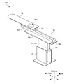
- FIG. 1 is a schematic perspective view showing an internal structure of a robot device according to a first aspect of the present disclosure
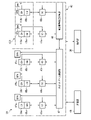
- FIG. 1 is a block diagram showing a control system of a robot device according to a first aspect of the present disclosure
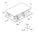
- FIG. 1 is a schematic perspective view showing a tilt adjusting device for a robotic device according to a first aspect of the present disclosure
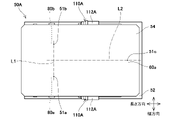
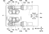
- FIG. 4 is a schematic diagram of the tilt adjustment device for the robot apparatus according to the first aspect of the present disclosure when viewed from the height direction
- FIG. 4 is a schematic view of the tilt adjustment device for the robot device according to the first aspect of the present disclosure when viewed from the height direction with the second member removed
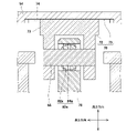
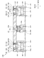
- FIG. 4C is a cross-sectional view taken along line VV in FIG.
- FIG. 4B showing the spherical plain bearing and its peripheral portion of the tilt adjusting device for the robotic device according to the first aspect of the present disclosure
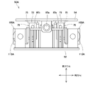
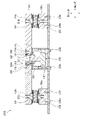
- FIG. 4 is a view along arrow VI in FIG. 3 showing the tilt adjusting device for the robot apparatus according to the first aspect of the present disclosure
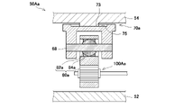
- FIG. 10 is a schematic cross-sectional view showing a spherical plain bearing and its peripheral portion in a first modified example of the tilt adjusting device for a robot device according to the first aspect of the present disclosure
- FIG. 10 is a schematic cross-sectional view showing a spherical plain bearing and its peripheral portion in a second modification of the tilt adjusting device for the robot device according to the first aspect of the present disclosure
- FIG. 11 is a schematic cross-sectional view showing a spherical plain bearing and its surroundings in a third modified example of the tilt adjusting device for a robot device according to the first aspect of the present disclosure
- FIG. 11 is a schematic cross-sectional view showing a spherical plain bearing and its peripheral portion in a fourth modified example of the tilt adjusting device for a robot device according to the first aspect of the present disclosure
- FIG. 11 is a schematic cross-sectional view showing a spherical plain bearing and its surroundings in a fifth modification of the tilt adjusting device for a robot device according to the first aspect of the present disclosure
- FIG. 11 is a schematic cross-sectional view showing a spherical plain bearing and its surroundings in a third modified example of the tilt adjusting device for a robot device according to the first aspect of the present disclosure
- FIG. 11 is a schematic cross-sectional view showing a spherical plain bearing and its surroundings in a fifth modification of the tilt adjusting device for a robot device according
- FIG. 11 is a schematic cross-sectional view showing a spherical plain bearing and its surroundings in a sixth modification of the tilt adjusting device for a robot device according to the first aspect of the present disclosure
- FIG. 10 is a schematic perspective view showing the internal structure of a robotic device according to a second aspect of the present disclosure
- FIG. 4 is a block diagram showing a control system of a robot device according to a second aspect of the present disclosure
- FIG. 11 is a schematic perspective view showing a tilt adjustment device for a robotic device according to a second aspect of the present disclosure
- FIG. 4 is a cross-sectional view along the height direction showing a tilt adjusting device for a robot device according to a second aspect of the present disclosure
- FIG. 10 is a schematic perspective view showing part of a height position adjustment mechanism included in a tilt adjustment device for a robot device according to a second aspect of the present disclosure
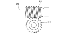
- FIG. 5 is a schematic diagram of a worm gear included in a tilt adjustment device for a robot device according to a second aspect of the present disclosure
- FIG. 7 is an exploded perspective view showing a spherical plain bearing, a male screw member, and a female screw member included in the tilt adjusting device for the robot device according to the second aspect of the present disclosure
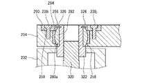
- FIG. 4 is a cross-sectional view along the height direction showing the spherical plain bearing provided in the tilt adjusting device for the robot device according to the second aspect of the present disclosure and its peripheral portion, before adjusting the tilt of the bed plate with respect to the wrist of the robot arm; It is a cross-sectional view showing the state of.
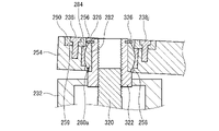
- FIG. 10 is a cross-sectional view along the height direction showing the spherical plain bearing and its peripheral portion provided in the tilt adjusting device for the robot device according to the second aspect of the present disclosure, after adjusting the tilt of the bed plate with respect to the wrist of the robot arm; It is a cross-sectional view showing the state of.
- FIG. 10 is a cross-sectional view along the height direction showing the spherical plain bearing and its peripheral portion provided in the tilt adjusting device for the robot device according to the second aspect of the present disclosure, after adjusting the tilt of the bed plate with respect to the wrist of the robot arm; It is a cross-sectional view showing the state of.
- FIG. 10 is a cross-sectional view along the height direction showing a first modification of the tilt adjusting device for the robot device according to the second aspect of the present disclosure
- FIG. 11 is a cross-sectional view along the height direction showing a second modification of the tilt adjusting device for the robot device according to the second aspect of the present disclosure
- FIG. 11 is a schematic perspective view showing a state in which a robot apparatus according to another second aspect of the present disclosure is applied to a semiconductor manufacturing apparatus
- FIG. 11 is a block diagram showing a control system of a robot device according to a third aspect of the present disclosure
- FIG. FIG. 11 is a schematic perspective view showing a tilt adjustment device for a robotic device according to a third aspect of the present disclosure
- FIG. 11 is a cross-sectional view along the height direction showing a tilt adjusting device for a robot device according to a third aspect of the present disclosure
- FIG. 11 is a schematic perspective view showing part of a height position adjustment mechanism included in a tilt adjustment device for a robot device according to a third aspect of the present disclosure
- FIG. 11 is a schematic diagram of a worm gear included in a tilt adjustment device for a robot device according to a third aspect of the present disclosure
- FIG. 11 is an exploded perspective view showing a spherical plain bearing, a male screw member, and a female screw member included in the tilt adjusting device for the robot device according to the third aspect of the present disclosure
- FIG. 11 is a cross-sectional view along the height direction showing a tilt adjusting device for a robot device according to a third aspect of the present disclosure
- FIG. 11 is a schematic perspective view showing part of a height position adjustment mechanism included in a tilt adjustment device for a robot device according to a third aspect of the present disclosure
- FIG. 10 is a cross-sectional view along the height direction showing the spherical plain bearing and its peripheral portion provided in the tilt adjusting device for the robot device according to the third aspect of the present disclosure, and is a cross-sectional view showing a state before adjusting the tilt of the blade.
- FIG. 10 is a cross-sectional view along the height direction showing the spherical plain bearing and its peripheral portion provided in the tilt adjusting device for the robot device according to the third aspect of the present disclosure, and is a cross-sectional view showing the state after the tilt of the blade is adjusted.
- FIG. 11 is a schematic diagram showing a first modified example of a semiconductor manufacturing apparatus to which a robot device according to a third aspect of the present disclosure is applied; FIG.
- FIG. 11 is a schematic diagram showing a second modified example of a semiconductor manufacturing apparatus to which a robot device according to a third aspect of the present disclosure is applied;
- FIG. 10 is a cross-sectional view showing a third modified example of a semiconductor manufacturing apparatus to which a robot apparatus according to a third aspect of the present disclosure is applied, and is a cross-sectional view along the height direction of an inclination adjusting device included in the semiconductor manufacturing apparatus.
- FIG. 14 is a cross-sectional view showing a fourth modification of the semiconductor manufacturing apparatus to which the robot apparatus according to the third aspect of the present disclosure is applied, and is a cross-sectional view along the height direction of the tilt adjusting device included in the semiconductor manufacturing apparatus.
- FIG. 1 is a schematic perspective view showing the internal structure of the robot apparatus according to this aspect.
- a robot apparatus 10A according to this aspect is applied to a radiotherapy room, and is configured as a treatment robot apparatus and, by extension, a medical robot apparatus.
- a radiotherapy room includes a gantry for irradiating a patient with radiation such as X-rays.
- the robotic device 10A is configured as a bed for transporting the patient to the appropriate position within the gantry. The patient is positioned while lying on the bed board 28 of the robotic device 10A with the assistance of medical staff. Then, the patient is transported to an appropriate position within the gantry by the robot device 10A, after which the patient is irradiated with radiation by the gantry and radiotherapy is performed.
- the robot apparatus 10A includes a base 12, a robot arm 20 connected to the base 12, and a link 22c provided as a wrist portion of the robot arm 20. It has an adjusting device 50A and a bed plate 28 attached to the robot arm 20 via the tilt adjusting device 50A.
- a state is shown in which a housing for accommodating them is removed.
- the robot arm 20 extends in the height direction and is connected to the upper part of the base 12 via a joint 24a (joint) so as to reciprocate in the height direction with respect to the base 12. and a link 22a extending in the horizontal plane in the longitudinal direction shown in FIG. 1, and a joint portion 24b (same as above) at the tip of the link 22a so as to reciprocate in the width direction shown in the figure with respect to the link 22a. and a link 22b that extends in the horizontal plane and is connected to the upper surface of the link 22b via a joint 24c (same as above) so that it can reciprocate in the longitudinal direction with respect to the link 22b. and a link 22c as a wrist portion to be connected.
- a joint 24a joint
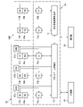
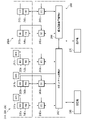
- FIG. 2 is a block diagram showing the control system of the robot device according to this aspect.
- the robot device 10A further includes a robot controller 40 for controlling the operations of the robot arm 20 and the tilt adjustment device 50A.
- the robot control device 40 has a robot arm control section 42 for servo-controlling the operation of the robot arm 20 and an inclination adjustment device control section 44 for servo-controlling the operation of the inclination adjustment device 50A.
- the robot controller 40 is provided within the base 12, for example.
- a signal line is connected between the robot arm control section 42 and the tilt adjustment device control section 44 so as to enable two-way communication.
- the robot arm control section 42 and the tilt adjustment device control section 44 may be configured as an integrated control section.
- the robot control device 40 may be configured as a host control device that controls the robot arm control section 42 and the tilt adjustment device control section 44 .
- the robot arm 20 has drive servo motors 48a to 48c, encoders 33a to 33c for detecting rotation angles of the servo motors 48a to 48c, and outputs of the servo motors 48a to 48c corresponding to the joints 24a to 24c.
- a reducer for reducing speed and increasing torque and brakes 47a-47c are provided.
- Brakes 47a-47c may each include a first brake and a second brake. By mounting two brakes on each of the joints 24a to 24b in this manner, safety can be improved.
- the brake may include an electromagnetic brake.
- the tilt adjusting device 50A also includes a height position adjusting mechanism 100A (second height position adjusting mechanism) provided in each of the spherical plain bearings 80a and 80b (second spherical plain bearing, third spherical plain bearing) described later.
- Servomotors 49a and 49b for driving and encoders 113a and 113b for detecting rotation angles of the servomotors 49a and 49b are provided corresponding to the pinion 130 which will be described later.
- the tilt adjusting device 50A is further provided with reduction gears for reducing the output of the servomotors 49a and 49b to increase torque, and brakes 147a and 147b.
- the brakes 147a and 147b may be doubled like the brakes 47a to 47c described above. Also, the brakes 147a and 147b may include electromagnetic brakes.
- the size of the motor can be reduced.
- the brakes 147a and 147b even if the servo motors 49a and 49b fail and become uncontrollable, the height position adjusting mechanism 100A can be safely stopped and the height can be maintained.
- the robot arm control unit 42 controls the motion of the robot arm 20 based on the motion command.
- Servo control units 43 a to 43 c are electrically connected to the robot arm control unit 42 .
- Servo motors 48a to 48c and encoders 33a to 33c are electrically connected to the servo controllers 43a to 43c.
- Brakes 47 a to 47 c are electrically connected to the robot arm control section 42 .
- the tilt adjusting device control section 44 controls the operation of the tilt adjusting device 50A based on the operation command.
- Servo controllers 45a and 45b are electrically connected to the tilt adjusting device 50A.
- a servo motor 49a and an encoder 113a are electrically connected to the servo controller 45a.
- a servo motor 49b and an encoder 113b are electrically connected to the servo controller 45b.
- Brakes 147 a and 147 b are electrically connected to the tilt adjustment device control section 44 .
- the robot device 10A further includes an operation unit 36 for receiving operation input from the medical staff as a user interface for receiving operation input regarding at least one of the robot arm 20 and the tilt adjustment device 50A.
- the operation unit 36 includes at least an input unit that receives operation input from the medical staff and an output unit that outputs the current state to the medical staff.
- the inputs may include, for example, contact sensors, membrane switches, joysticks, enable switches, and the like.
- the output unit may include a display, a speaker, an indicator light, and the like.
- a position/orientation command for the tip of the robot arm 20 is input to the robot arm control unit 42 based on the motion command input to the operation unit 36 .
- the robot arm control unit 42 generates and outputs a position command value based on the position/orientation command and the rotation angles detected by the encoders 33a to 33c.
- the servo control units 43a to 43c that have obtained the position command values generate and output drive command values (torque command values) based on the rotation angles and position command values detected by the encoders 33a to 33c.
- the amplifier circuit that has acquired this drive command value supplies a drive current corresponding to the drive command value to the servo motors 48a to 48c. In this manner, the servomotors 48a to 48c are servo-controlled so that the tip of the robot arm 20 reaches the position and orientation corresponding to the position and orientation command.
- the robot control device 40 is provided with a storage unit 46 from which data can be read out to the robot control device 40 .
- the storage unit 46 pre-stores motion control of the robot arm 20, motion control of the tilt adjustment device 50A, input/output information of the operation unit 36, information necessary for treatment, and the like.
- the tilt adjustment device control section 44 generates and outputs a position command value based on the operation command input from the operation section 36 and the rotation angles detected by the encoders 113a and 113b.
- the servo control units 45a and 45b that have obtained the position command values generate and output drive command values or torque command values based on the rotation angles and position command values detected by the encoders 113a and 113b.
- the amplifier circuit that has acquired this drive command value supplies a drive current corresponding to the drive command value to the servo motors 49a and 49b.
- the servomotors 49a and 49b are servo-controlled so that the tips of the height position adjusting mechanisms 100A and 100A of the tilt adjusting device 50A reach the height positions corresponding to the position command values.
- the robot arm controller 42 and the tilt adjustment device controller 44 communicate with each other and share information including position command values.
- the robot arm 20 and the tilt adjustment device 50A operate cooperatively based on the shared information.
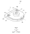
- FIG. 3 is a schematic perspective view showing the tilt adjusting device for the robot device according to this aspect.
- the tilt adjusting device 50A includes a plate-shaped first member 52 provided on the link 22c (wrist portion) side and a plate-shaped member provided on the bed plate 28 side so as to face the first member 52. and a second member 54 of The tilt adjusting device 50A can adjust the tilt of the second member 54 with respect to the first member 52 .
- the inclination adjusting device 50A can adjust the inclination of the bed plate 28 attached to the second member 54 with respect to the link 22c (wrist portion) attached to the first member 52.
- FIG. 1 is a schematic perspective view showing the tilt adjusting device for the robot device according to this aspect.
- the tilt adjusting device 50A includes a plate-shaped first member 52 provided on the link 22c (wrist portion) side and a plate-shaped member provided on the bed plate 28 side so as to face the first member 52. and a second member 54 of The tilt adjusting device 50A can adjust
- FIG. 4A is a schematic view of the tilt adjusting device of the robot device according to this aspect when viewed from the height direction.
- FIG. 4B is a schematic view of the tilt adjusting device for the robot device according to this aspect when viewed from the height direction with the second member removed.
- the tilt adjusting device 50A includes three fulcrums 51a to 51c provided at different positions when viewed from the height direction in order to support the second member 54, and a fulcrum Two spherical sliding bearings 80a and 80b provided corresponding to 51a and 51b, and a universal joint 60a provided corresponding to the fulcrum 51c are provided.
- a spherical plain bearing 80 a is provided at the fulcrum 51 a between the first member 52 and the second member 54 .
- a spherical plain bearing 80b is provided between the first member 52 and the second member 54 at the fulcrum 51b.
- the universal joint 60a is provided between the first member 52 and the second member 54 at the fulcrum 51c.
- the spherical plain bearings 80a and 80b are arranged on the distal end side of the robot device 10A, and the universal joint 60a is arranged on the proximal end side of the robot device 10A.
- the universal joint 60a may be arranged on the distal end side of the robot device 10A, and the spherical sliding bearings 80a and 80b may be arranged on the proximal end side of the robot device 10A.
- the universal joint 60a is positioned on the perpendicular bisector L2 of the line segment L1 connecting the spherical plain bearing 80a and the spherical plain bearing 80b when viewed from the height direction.
- the universal joint 60a has a pitch axis parallel to the line segment L1 in a plane perpendicular to the height direction, and the second member 54 can tilt around the pitch axis.
- a universal joint 60a is attached to the lower surface thereof as shown.
- the universal joint 60a has a roll axis parallel to the perpendicular bisector L2 in a plane orthogonal to the height direction, and the second member 54 is tiltable about the roll axis.
- a universal joint 60a is attached to the lower surface.
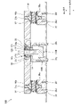
- FIG. 5 is a cross-sectional view taken along the line VV in FIG. 4B showing the spherical sliding bearing and its surroundings of the tilt adjusting device for the robot device according to this embodiment.
- the spherical plain bearing 80a has an inner ring 82a (second inner ring) and an outer ring 84a.
- the inner ring 82a is attached to the second member 54 via the shaft 68 and the sliding structure 70.
- the shaft 68 passes through the horizontally extending shaft hole of the inner ring 82a and the horizontally extending shaft hole of the outer ring 84a that is coaxial with this shaft hole.
- both ends of the shaft 68 are fixed to the sliding bodies 72 that are part of the sliding structure 70 respectively.
- the sliding structure 70 has the above-described sliding body 72 and a sliding surface 75 positioned above the sliding body 72 and extending along the horizontal direction.
- the sliding body 72 has a substantially U-shaped shape which is turned upside down in the cross-sectional view of FIG. 5, and has a plate 73 at its upper end.
- the sliding surface 75 is slid on the plate 73 .
- the sliding surface 75 is part of a recess 74 provided on the lower surface of the second member 54 .
- the sliding surface 75 is also indicated by broken lines in FIG. 4B. That is, the plate 73 is horizontally slidable within the range indicated by the dashed line in FIG. 4B.
- the outer ring 84 a is fixed to the interposed member 78 .
- the interposed member 78 has a cylindrical hole, and the outer ring 84a is fixed inside the hole.
- the intervening member 78 is supported by the first member 52 via other members (for example, a height position adjusting mechanism 100A to be described later).
- the first member 52 supports the second member 54 via the shafts 68 extending horizontally from the inner ring 82a of the spherical plain bearing 80a to both sides.
- Spherical plain bearing 80b and its peripheral portion have the same structure as spherical plain bearing 80a described above, and therefore description thereof will not be repeated here.
- the height position adjustment mechanisms 100A and 100A are respectively composed of a motor unit 110A, a pinion 130 rotationally driven by a motor 112A (second motor) of the motor unit 110A, and a and a mating rack 132 .
- the axes of rotation of motor 112A and pinion 130 are coaxial with each other and extend along a horizontal plane parallel to perpendicular bisector L2 shown in FIGS. 4A and 4B.
- the rack 132 extends in the height direction.
- a surface of rack 132 opposite pinion 130 is connected to interposed member 78 . Note that the rotation axes of the motor 112A and the pinion 130 may not be coaxial with each other and may be shifted.
- FIG. 6 is a view taken along line VI in FIG. 3, showing the tilt adjusting device for the robot apparatus according to this embodiment.
- the right side of the bed board 28 (the far side in the width direction in FIG. 1) is slightly lower than the left side of the bed board 28 (the front side in the width direction in FIG. 1).
- the motor 112A of the height position adjusting mechanism 100A located on the right side of the bed plate 28 (left side in FIG. 6) rotates the pinion 130 to raise the rack 132 meshing with the pinion 130.
- the spherical sliding bearing 80b fixed to the rack 132 via the intervening member 78 rises.
- the plate 73 attached to the upper side of the spherical plain bearing 80b slides on the corresponding sliding surface 75.
- the plate 73 attached to the upper side of the spherical sliding bearing 80a located on the left side (right side in FIG. 6) of the bed plate 28 also slides on the corresponding sliding surface 75.
- the universal joint 60a positioned at the center of the bed plate 28 in the width direction rotates around the roll axis parallel to the perpendicular bisector L2 shown in FIGS. 4A and 4B.
- the inclination of the bed plate 28 in the width direction can be adjusted as described above.
- the adjustment mode of the inclination of the bed plate 28 described above is merely an example.
- the inclination of the bed plate 28 in the width direction may be adjusted by lowering the rack 132 that meshes with the pinion 130 .
- the robot apparatus 10A includes a tilt adjustment device 50A having a universal joint 60a and spherical sliding bearings 80a and 80b in order to adjust the tilt of the second member 54 with respect to the first member 52.
- a tilt adjustment device 50A having a universal joint 60a and spherical sliding bearings 80a and 80b in order to adjust the tilt of the second member 54 with respect to the first member 52.
- the tilt adjusting device 50A can be provided compactly on the link 22c (wrist portion) of the robot arm 20.
- the tilt adjusting device 50A is not provided with the universal joint 60a and the spherical plain bearings 80a and 80b, and the tilt of the second member 54 with respect to the first member 52 is adjusted by the height position adjusting mechanisms 100A and 100A. think. In such a case, if the second member 54 is tilted with respect to the first member 52 by operating one of the two height position adjusting mechanisms 100A, the second member 54 will be distorted. Further, since the rack 132 tends to tilt integrally with the second member 54, for example, the rack 132 is pressed against the pinion 130 and the pinion 130 cannot rotate.
- the tilt adjusting device 50A adjusts the outer rings 84a of the spherical plain bearings 80a and 80b, and , the pitch axis and the roll axis of the universal joint 60a are inclined with respect to a plane perpendicular to the height direction.
- the second member 54 can be accurately tilted with respect to the first member 52 without the second member 54 being distorted and the pinion 130 being prevented from rotating.
- the tilt adjusting device 50A can reliably adjust the tilt of the second member 54 with respect to the first member 52, and furthermore, the tilt of the bed plate 28 with respect to the link 22c (wrist portion) of the robot arm 20 can be adjusted.
- the tilt adjusting device 50A can reliably adjust the tilt of the second member 54 with respect to the first member 52, and furthermore, the tilt of the bed plate 28 with respect to the link 22c (wrist portion) of the robot arm 20 can be adjusted.
- the rack 132 is moved in the height direction by rotationally driving the pinion 130 with the motor 112A.
- the tilt adjusting device 50A controls the operation of the motor 112A based on the rotational position of the motor 112A detected by the encoders 113a and 113b (in other words, servo-controls the servo motors 49a and 49b). ), the inclination of the second member 54 relative to the first member 52 can be adjusted more precisely.
- the tilt adjusting device 50A includes the sliding structures 70 between the spherical plain bearing 80a and the second member 54 and between the spherical plain bearing 80b and the second member 54, respectively.
- the first member 52 supports the second member 54 via the shaft 68 extending horizontally from the inner rings 82a, 82a of the spherical plain bearings 80a, 80b to both sides.
- the first member 52 supports the second member 54 via shafts extending downward from the inner rings 82a, 82a. It can be received over a wider area in the horizontal plane. Therefore, it is possible to improve the strength of the tilt adjusting device 50A.
- the spherical plain bearing 80b is further provided, so that the inclination of the second member 54 with respect to the first member 52 can be easily and accurately adjusted.
- the universal joint 60a is positioned on the perpendicular bisector L2 of the line segment L1 connecting the spherical plain bearing 80a and the spherical plain bearing 80b when viewed from the height direction.
- the inclination of the second member 54 with respect to 52 can be adjusted more easily and accurately.
- brakes 147a and 147b for braking the motor 112A are further provided.
- two brakes may be provided for one motor 112A.
- the brakes 147a and 147b may include electromagnetic brakes.
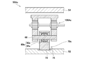
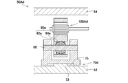
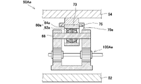
- FIG. 7A to 7F show schematic cross-sectional views of the spherical sliding bearing and its peripheral portion among the first to sixth modifications of the tilt adjusting device for the robot apparatus according to the first aspect described above.
- the tilt adjusting devices according to the first to sixth modifications are provided in the same robot device 10A as the tilt adjusting device 50A according to the first aspect described above, and except for the sliding structure and the height position adjusting mechanism, It has the same structure as the tilt adjusting device 50A according to the first aspect described above. Therefore, the same reference numerals are given to the same parts, and the same description will not be repeated.
- a plate 73 of a sliding structure 70a is provided in a manner protruding from the lower surface of a second member 54, and a surface 75 to be slid of the sliding structure 70a is , are provided on the upper surface of the member to which both ends of the shaft 68 projecting from the inner ring 82a to both sides are fixed.
- a height position adjusting mechanism 100Aa is provided between the outer ring 84a and the first member 52 .
- the plate 73 of the sliding structure 70b is the lower end of the member to which the outer ring 84a is fixed, and the sliding surface 75 of the sliding structure 70b is It is provided on the upper surface of a member fixed to the first member 52 .
- a height position adjusting mechanism 100Ab is provided between a member to which both ends of the shaft 68 projecting from the inner ring 82a to both sides are fixed and the second member 54. .
- the tilt adjusting device 50Ab having such a structure, it is possible to reliably adjust the tilt of the second member 54 with respect to the first member 52, like the tilt adjusting device 50A according to the first aspect described above.
- the plate 73 of the sliding structure 70b is the upper end of the member fixed to the first member 52, and the sliding surface 75 of the sliding structure 70b is fixed to the outer ring 84a. It may be provided at the lower end of the member that
- the plate 73 of the sliding structure 70c is the lower end of the member to which the outer ring 84a is fixed, and the sliding surface 75 of the sliding structure 70c is It is provided on the upper surface of the first member 52 .
- the height position adjusting mechanism 100Ac is provided between the second member 54 and a member to which both ends of the shaft 68 extending from the inner ring 82a are fixed. .
- the tilt adjusting device 50Ac having such a structure, it is possible to reliably adjust the tilt of the second member 54 with respect to the first member 52, like the tilt adjusting device 50A according to the first aspect described above.
- the plate 73 of the sliding structure 70c is provided so as to protrude from the upper surface of the first member 52, and the sliding surface 75 of the sliding structure 70c is the member to which the outer ring 84a is fixed. It may be the lower end.
- a plate 73 of a sliding structure 70d is provided in a manner protruding from the upper surface of the first member 52, and a sliding surface 75 of the sliding structure 70d is , and both ends of the shaft 68 projecting from the inner ring 82a to both sides are provided on the lower surface of the member to which they are fixed.
- a height position adjusting mechanism 100Ad is provided between the second member 54 and the member to which the outer ring 84a is fixed.
- the tilt adjusting device 50Ad having such a structure, it is possible to reliably adjust the tilt of the second member 54 with respect to the first member 52, like the tilt adjusting device 50A according to the first aspect described above.
- the plate 73 of the sliding structure 70d is provided in such a manner that both ends of the shaft 68 projecting from the inner ring 82a to both sides protrude from the lower surface of the member to which the sliding structure 70d is fixed.
- the sliding surface 75 may be provided on the upper surface of the first member 52 .
- the plate 73 of the sliding structure 70e is the upper end portion of the member to which the outer ring 84a is fixed, and the sliding surface 75 of the sliding structure 70e is It is provided on the lower surface of a member fixed to the second member 54 .
- the height position adjusting mechanism 100Ae is provided between the first member 52 and a member to which both ends of the shaft 68 extending from the inner ring 82a are fixed. .
- the tilt adjusting device 50Ae having such a structure, it is possible to reliably adjust the tilt of the second member 54 with respect to the first member 52, like the tilt adjusting device 50A according to the first aspect described above.
- the plate 73 of the sliding structure 70e is the lower end of the member fixed to the second member 54, and the sliding surface 75 of the sliding structure 70e is fixed to the outer ring 84a. It may be provided on the upper surface of a member that
- the plate 73 of the sliding structure 70f is the upper end portion of the member to which the outer ring 84a is fixed, and the sliding surface 75 of the sliding structure 70f is It is provided on the lower surface of the second member 54 .
- the height position adjusting mechanism 100Af is provided between the first member 52 and a member to which both ends of the shaft 68 extending from the inner ring 82a are fixed. .
- the tilt adjusting device 50Af having such a structure, it is possible to reliably adjust the tilt of the second member 54 with respect to the first member 52, like the tilt adjusting device 50A according to the first aspect described above.
- the plate 73 of the sliding structure 70f is provided so as to protrude from the lower surface of the second member 54, and the sliding surface 75 of the sliding structure 70f is fixed to the outer ring 84a. It may be provided on the upper surface of the member.
- the inner ring 82a is attached to one of the first member 52 and the second member 54
- the outer ring 84a is attached to the other of the first member 52 and the second member 54
- the second member relative to the first member 52 is mounted.
- 54 can be accurately adjusted
- the sliding structure and the height position adjusting mechanism can be the tilt adjusting device 50A according to the above aspect and the tilt adjusting devices 50Aa to 50Aa according to the first to sixth modifications.
- a structure other than that described for 50Af may be used.
- the robot apparatus 10A is applied to a radiotherapy room and configured as a treatment robot apparatus and, by extension, a medical robot apparatus.
- the robot apparatus 10A is not limited to this case, and the robot apparatus 10A may be applied to any treatment room other than the radiotherapy room and may be configured as a medical bed, or may be applied to an operating room, a surgical robot, and eventually a medical treatment room. It may be configured as a robot device for use.
- the robot apparatus 10A is applied to sites other than medical care (for example, semiconductor manufacturing sites, food manufacturing sites, automobile manufacturing sites, distribution sites, etc.) and robot devices other than medical robot devices (for example, semiconductor manufacturing robots). equipment, food manufacturing robots, automobile manufacturing robots, distribution robots, etc.).
- the tilt adjusting device 50A described above has the three fulcrums 51a to 51c for supporting the second member .
- the tilt adjusting device may have a structure having two fulcrums or four or more fulcrums at different positions when viewed in the height direction in order to support the second member. good.
- the tilt adjusting device may have a structure having at least two fulcrums at different positions when viewed from the height direction.
- one fulcrum is provided with the spherical sliding bearing 80a, and the other is provided with a spherical sliding bearing 80a.
- a universal joint 60a may be provided at the fulcrum.
- the height position adjustment mechanism 100A has a structure including the pinion 130 and the rack 132 .
- the height position adjustment mechanism may have a structure having a direct acting actuator, for example.
- the height position adjusting mechanism has, for example, a male threaded member and a female threaded member screwed into the male threaded member, and one of the male threaded member and the female threaded member is axially
- the structure may be such that one of them moves in the height direction with respect to the other by rotating.
- the height position adjustment mechanism may have a structure other than the above.
- the first member 52 is attached to the link 22c (wrist portion) of the robot arm 20, and the second member 54 is attached to the bed plate 28 (in other words, the first member 52 is attached to the robot arm).
- the link 22c (wrist portion) of the arm 20 is provided separately and the second member 54 is provided separately from the bed plate 28) has been described.
- the present invention is not limited to this case, and for example, the first member may be configured as part of the link 22c (wrist portion) of the robot arm, and the second member may be configured as part of the bed board.
- the robot arm 20 described above has a structure in which the base 12 and the links 22a to 22c are connected via the joints 24a to 24c.
- the robot arm is not limited to this case, and the robot arm may be, for example, a vertically articulated robot arm, or may be a robot arm with another structure.
- FIG. 8 is a schematic perspective view showing the internal structure of the robot apparatus according to this aspect.
- the robot apparatus 10B according to this aspect is applied to a radiotherapy room, and is configured as a treatment robot apparatus and, by extension, a medical robot apparatus.
- a radiotherapy room includes a gantry for irradiating a patient with radiation such as X-rays.
- the robotic device 10B is configured as a bed for transporting the patient to an appropriate position within the gantry. The patient is positioned lying on the bed board 28 of the robotic device 10B with the assistance of medical staff. Then, the patient is transported to an appropriate position within the gantry by the robot apparatus 10B, after which the patient is irradiated with radiation by the gantry and radiotherapy is performed.
- the robot device 10B includes a base 12, a robot arm 20 connected to the base 12, and a link 22c provided as a wrist portion of the robot arm 20. It has an adjusting device 50B and a bed plate 28 attached to the robot arm 20 via the tilt adjusting device 50B.
- FIG. 8 shows a state in which a housing for housing them has been removed.
- the robot arm 20 extends in the height direction and is connected to the upper part of the base 12 via a joint 24a (joint) so as to reciprocate in the height direction with respect to the base 12. and a joint portion 24b (same as above) at the tip of the link 22a extending in the longitudinal direction shown in FIG. and a link 22b that extends in the horizontal plane and is connected to the upper surface of the link 22b via a joint 24c (same as above) so that it can reciprocate in the longitudinal direction with respect to the link 22b. and a link 22c as a wrist portion to be connected.
- FIG. 9 is a block diagram showing the control system of the robot device according to this aspect.
- the robot device 10B further includes a robot controller 40 for controlling the operations of the robot arm 20 and the tilt adjustment device 50B.
- the robot control device 40 has a robot arm control section 42 for servo-controlling the operation of the robot arm 20 and an inclination adjustment device control section 44 for servo-controlling the operation of the inclination adjustment device 50B.
- the robot controller 40 is provided within the base 12, for example.
- a signal line is connected between the robot arm control section 42 and the tilt adjustment device control section 44 so as to enable two-way communication.
- the robot arm control section 42 and the tilt adjustment device control section 44 may be configured as an integrated control section.
- the robot control device 40 may be configured as a host control device that controls the robot arm control section 42 and the tilt adjustment device control section 44 .
- the robot arm 20 has drive servo motors 48a to 48c, encoders 33a to 33c for detecting rotation angles of the servo motors 48a to 48c, and outputs of the servo motors 48a to 48c corresponding to the joints 24a to 24c.
- a reducer for reducing speed and increasing torque and brakes 47a-47c are provided.
- Brakes 47a-47c may each include a first brake and a second brake. By mounting two brakes on each of the joints 24a to 24b in this manner, safety can be improved.
- the brake may include an electromagnetic brake.
- the inclination adjusting device 50B corresponds to the male screw member 120 of the height position adjusting mechanism 100B (first height position adjusting mechanism) provided in each of the spherical plain bearings 80c and 80d (first spherical plain bearings) described later.
- Servomotors 49a and 49b for driving and encoders 113a and 113b for detecting rotation angles of the servomotors 49a and 49b are provided.
- the tilt adjusting device 50B may be further provided with a reducer for reducing the output of the servo motors 49a and 49b to increase the torque, and a brake.
- This brake may be duplicated like the brakes 47a to 47c described above.
- the brake may include an electromagnetic brake.
- the robot arm control unit 42 controls the motion of the robot arm 20 based on the motion command.
- Servo control units 43 a to 43 c are electrically connected to the robot arm control unit 42 .
- Servo motors 48a to 48c and encoders 33a to 33c are electrically connected to the servo controllers 43a to 43c.
- Brakes 47 a to 47 c are electrically connected to the robot arm control section 42 .
- the tilt adjusting device control section 44 controls the operation of the tilt adjusting device 50B based on the operation command.
- Servo controllers 45a and 45b are electrically connected to the tilt adjusting device 50B.
- a servo motor 49a and an encoder 113a are electrically connected to the servo controller 45a.
- a servo motor 49b and an encoder 113b are electrically connected to the servo controller 45b.
- a brake may be electrically connected to the tilt adjustment device control section 44 .
- the robot device 10B further includes an operation unit 36 for receiving operation input from the medical staff as a user interface for receiving operation input regarding at least one of the robot arm 20 and the tilt adjustment device 50B.
- the operation unit 36 includes at least an input unit that receives operation input from the medical staff and an output unit that outputs the current state to the medical staff.
- the inputs may include, for example, contact sensors, membrane switches, joysticks, enable switches, and the like.
- the output unit may include a display, a speaker, an indicator light, and the like.
- a position/orientation command for the tip of the robot arm 20 is input to the robot arm control unit 42 based on the motion command input to the operation unit 36 .
- the robot arm control unit 42 generates and outputs a position command value based on the position/orientation command and the rotation angles detected by the encoders 33a to 33c.
- the servo control units 43a to 43c that have obtained the position command values generate and output drive command values (torque command values) based on the rotation angles and position command values detected by the encoders 33a to 33c.
- the amplifier circuit that has acquired this drive command value supplies a drive current corresponding to the drive command value to the servo motors 48a to 48c. In this manner, the servomotors 48a to 48c are servo-controlled so that the tip of the robot arm 20 reaches the position and orientation corresponding to the position and orientation command.
- the robot control device 40 is provided with a storage unit 46 from which data can be read out to the robot control device 40 .
- the storage unit 46 preliminarily stores motion control of the robot arm 20, motion control of the tilt adjusting device 50B, input/output information of the operation unit 36, information necessary for treatment, and the like.
- the tilt adjustment device control section 44 generates and outputs a position command value based on the operation command input from the operation section 36 and the rotation angles detected by the encoders 113a and 113b.
- the servo control units 45a and 45b that have obtained the position command values generate and output drive command values or torque command values based on the rotation angles and position command values detected by the encoders 113a and 113b.
- the amplifier circuit that has acquired this drive command value supplies a drive current corresponding to the drive command value to the servo motors 49a and 49b.
- the servomotors 49a and 49b are servo-controlled so that the tips of the height position adjusting mechanisms 100B and 100B of the tilt adjusting device 50B reach the height positions corresponding to the position command values.
- the robot arm controller 42 and the tilt adjustment device controller 44 communicate with each other and share information including position command values.
- the robot arm 20 and the tilt adjustment device 50B operate cooperatively based on the shared information.
- FIG. 10 is a schematic perspective view showing a tilt adjusting device for a robot device according to this aspect.
- the tilt adjusting device 50B includes a plate-shaped first member 52 provided on the link 22c (wrist portion) side and a plate-shaped member provided on the bed plate 28 side so as to face the first member 52. and a second member 54 of The tilt adjusting device 50B can adjust the tilt of the second member 54 with respect to the first member 52 .
- the inclination adjusting device 50B can adjust the inclination of the bed plate 28 attached to the second member 54 with respect to the link 22c (wrist portion) attached to the first member 52.
- FIG. 10 is a schematic perspective view showing a tilt adjusting device for a robot device according to this aspect.
- the tilt adjusting device 50B includes a plate-shaped first member 52 provided on the link 22c (wrist portion) side and a plate-shaped member provided on the bed plate 28 side so as to face the first member 52. and a second member 54 of The tilt adjusting device
- the tilt adjusting device 50B is provided corresponding to three fulcrums 51a to 51c provided at different positions when viewed from the height direction, and the fulcrums 51a to 51c in order to support the second member 54.
- Three spherical plain bearings 60b, 80c, 80d are provided.
- the spherical plain bearings 60b, 80c, 80d are provided between the first member 52 and the second member 54, respectively.
- a spherical plain bearing 80c is provided at the fulcrum 51a
- a spherical plain bearing 80d is provided at the fulcrum 51b
- a spherical plain bearing 60b is provided at the fulcrum 51c.
- the spherical sliding bearing 60b is provided at the tip of the center axis L extending from the base end to the tip of the center in the width direction of the tilt adjustment device 50B.
- the spherical plain bearings 80c and 80d are respectively provided closer to the base end side of the robot device 10B than the spherical plain bearing 60b. Further, the spherical plain bearings 80c and 80d are arranged so as to be symmetrical with respect to the central axis L as the axis of symmetry when viewed from the height direction.
- the spherical plain bearings 80c and 80d are arranged at the same height position higher than the spherical plain bearing 60b.
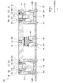
- FIG. 11 is a cross-sectional view along the height direction showing the tilt adjusting device for the robot device according to this aspect.
- the sectional view of the central portion is taken along a plane different from the sectional views of the left and right portions. is. The same applies to FIGS. 16A, 16B, 20, 26A, and 26B, which will be described later.
- the spherical plain bearing 60b has an inner ring 62 and an outer ring 64.
- the spherical plain bearing 60b has an outer ring 64 attached to the first member 52 via the first intermediate member 30, and an inner ring 62 attached to the second member 54 with bolts 38a.
- the outer ring 64 is attached to the first intermediate member 30 by bolts 38b, 38c and the like, and the first intermediate member 30 is attached to the first member 52 by bolts 38d to 38f and the like.
- a height position adjusting mechanism 100B which will be described later, is not interposed between the outer ring 64 and the first member 52 .
- the spherical plain bearing 80c has an inner ring 82c (first inner ring) and an outer ring 84c (first outer ring).
- the spherical plain bearing 80 c has an inner ring 82 c attached to the first member 52 and an outer ring 84 c attached to the second member 54 .
- the second intermediate member 32 and the height position adjusting mechanism 100B are interposed.
- the first member 52, the height position adjusting mechanism 100B, and the second intermediate member 32 are connected to each other by bolts 38g, 38h, etc. that pass through the first member 52 and the height position adjusting mechanism 100B and reach the second intermediate member 32. Fixed.
- the spherical plain bearing 80d has the same structure as the spherical plain bearing 80c. is attached to the second member 54 . Therefore, a similar description of the spherical sliding bearing 80d will not be repeated here.
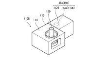
- FIG. 12 is a schematic perspective view showing a part of the height position adjusting mechanism included in the tilt adjusting device for the robot apparatus according to this aspect.
- the height position adjusting mechanism 100B includes a motor unit 110B, a male screw member 120 that is rotationally driven by a motor 112B (first motor) of the motor unit 110B, and a male screw member 120 that rotates. and a female screw member 122 (moving member) that moves in the height direction.
- the female screw member 122 can be moved in the height direction by being rotationally driven by the motor 112B.
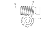
- FIG. 13 is a schematic diagram of a worm gear included in the tilt adjusting device for the robot device according to this aspect.
- the motor unit 110B and thus the height position adjustment mechanism 100B, includes a motor 112B and an encoder 113a shown by a dashed line in FIG. 12 for detecting the rotational position of the motor 112B.
- the housing 114 fixed to the motor 112B, and the housing 114 disposed in the housing 114 reduce the power of the motor 112B to reduce the power of the male screw member 120 and and a worm gear 115 (reduction mechanism) for outputting to the female screw member 122 .
- a servomotor 49a (or a servomotor 49b) is composed of the motor 112B and the encoders 113a and 113b. Note that the power of the motor 112B may be directly output to the male screw member 120.
- the worm gear 115 includes a rod-shaped worm 116 that is rotationally driven by the motor 112B, and a gear-shaped worm wheel 118 that meshes with the worm 116.
- the worm gear 115 has a self-locking mechanism for preventing the female screw member 122 from moving in the height direction due to an external force.
- the self-locking mechanism has the worm 116 as a rotating body, and the thread groove formed on the outer surface of the worm 116 has a relatively small lead angle.
- the predetermined value of the lead angle of the thread groove is, for example, 2 degrees or more and 4 degrees or less.
- the motor unit 110B further has a male screw member 120 as another rotating body fixed to the center of the worm wheel 118 of the worm gear 115 and extending in the height direction.
- the male screw member 120 rotates integrally with the worm wheel 118 .
- the thread groove formed on the outer surface of the male screw member 120 is formed with a relatively small lead angle. By setting the lead angle of the thread groove to a predetermined value, the external force applied to or transmitted to the male screw member 120 reduces the component that rotates the male screw member 120 .
- the predetermined value of the lead angle of the thread groove is, for example, 2 degrees or more and 4 degrees or less.
- the female screw member 122 is screwed into the male screw member 120 and configured to move in the height direction as the male screw member 120 rotates.
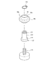
- FIG. 14 is an exploded perspective view showing a spherical sliding bearing, a male screw member and a female screw member provided in the tilt adjusting device for the robot device according to this aspect.
- the female screw member 122 has a cylindrical shaft portion 123 with a thread groove formed on its inner wall, and a flange 125 provided at the proximal end of the shaft portion 123 .
- An annular groove 124 is formed in the tip portion of the shaft portion 123 .
- the shaft portion 123 of the female screw member 122 is passed through the shaft hole 83 of the inner ring 82c of the spherical plain bearing 80c.
- the groove 124 of the shaft portion 123 is positioned along the upper end of the inner ring 82c.
- the spherical plain bearing 80 c is fixed to the female screw member 122 .
- the male screw member 120 is inserted into the female screw member 122 while screwing the male screw member 120 from the flange 125 side of the shaft hole of the female screw member 122 .
- the height position adjustment mechanism 100B is attached to the spherical slide bearing 80c.
- a similar height position adjusting mechanism 100B is also attached to the spherical slide bearing 80d, but the description thereof will not be repeated here.
- FIG. 15A is a cross-sectional view along the height direction showing the spherical plain bearing provided in the tilt adjusting device of the robot apparatus according to this embodiment and its peripheral portion, before adjusting the tilt of the bed plate with respect to the wrist of the robot arm. It is a cross-sectional view showing the state of.
- FIG. 15B is a cross-sectional view along the height direction showing the spherical plain bearing and its peripheral portion, and is a cross-sectional view showing a state after adjusting the tilt of the bed plate with respect to the wrist of the robot arm.
- the spherical plain bearing 80c to which the height position adjusting mechanism 100B is attached is inserted through the through hole 56 formed in the second member 54, and the outer edge portion of the lower surface of the outer ring 84c extends through the through hole 56. As shown in FIG. is placed on a protrusion 58 protruding from the lower end of the inner wall of the .
- the outer edge portion of the upper surface of the outer ring 84c contacts the central portion of the lower surface of the lid member 90 (specifically, the peripheral portion of the shaft hole of the lower surface of the lid member 90).
- the lid member 90 is fitted into the recess 59 formed in the second member 54 .
- the through hole 56 is formed in the central portion of the concave portion 59 when viewed from the height direction.
- the lid member 90 is fixed to the recess 59 of the second member 54 by bolts 38i, 38j and the like while being fitted into the recess 59. As shown in FIG. By fixing the cover member 90 to the recessed portion 59 of the second member 54 in this manner, the spherical slide bearing 80c is positioned within the through hole 56 formed in the second member 54 .
- FIGS. 15A and 15B an example of a mode of adjusting the tilt of the bed plate 28 with respect to the link 22c (wrist portion) of the robot arm 20 using the tilt adjusting device 50B described above will be described. 11, one side portion of the bed plate 28 attached to the left portion of the second member 54 is lower than the other side portion of the bed plate 28 attached to the right portion of the second member 54. A case will be described in which the tilt of the bed board 28 with respect to the link 22c (wrist portion) due to this is adjusted by the tilt adjusting device 50B.
- the male screw member 120 is rotationally driven via the worm gear 115 by the motor 112B.
- FIG. 15B shows how the female screw member 122 is sent upward by rotating the male screw member 120 to the right (in other words, how the female screw member 122 moves in the height direction).
- the second member 54 fixed to the outer ring 84c also tilts with respect to the plane perpendicular to the height direction. tilt.
- the inner ring 62 of the spherical plain bearing 60b slides on the contact surface of the outer ring 64
- the inner ring 62 and the bolt 38a fixed to the shaft hole of the inner ring 62 are tilted with respect to the plane orthogonal to the height direction.
- the outer ring 84c of the spherical plain bearing 80d also slides on the contact surface of the inner ring 82c and is inclined with respect to a plane orthogonal to the height direction.
- the first member 52 is attached to the link 22c (wrist portion), and the second member 54 is attached to the bed plate 28. Therefore, by tilting the second member 54 with respect to the plane orthogonal to the height direction as described above, the tilt of the bed plate 28 with respect to the link 22c (same as above) can be adjusted.
- the inclination of the second member 54 with respect to the first member 52 is adjusted by adjusting the height position of the spherical sliding bearing 80c by the height position adjusting mechanism 100B.
- the inclination of the second member 54 with respect to the first member 52 may be adjusted by adjusting the height position of the spherical sliding bearing 80d by the height position adjusting mechanism 100B.
- the robot apparatus 10B includes a tilt adjustment device 50B having spherical plain bearings 60b, 80c, 80d for adjusting the tilt of the second member 54 with respect to the first member 52. As shown in FIG. As a result, for example, compared to the conventional case where the inclination of the second member with respect to the first member is adjusted by an inclination adjusting device including a joint jack, a motor spindle device, and first and second lifting devices. , the link 22c (wrist portion) of the robot arm 20 can be compactly provided with the tilt adjusting device 50B.
- the tilt adjustment device 50B is not provided with the spherical plain bearings 60b, 80c, and 80d, and the tilt of the second member 54 with respect to the first member 52 is adjusted by the two height position adjustment mechanisms 100B.
- the second member 54 will be distorted.
- the female screw member 122 tends to tilt integrally with the second member 54 , the male screw member 120 cannot rotate inside the female screw member 122 .
- the tilt adjusting device 50B when the height position of the spherical plain bearing 80c is adjusted by the height position adjusting mechanism 100B, the outer rings 84c and 84d of the spherical plain bearings 80c and 80d are adjusted. , and the inner ring 62 of the spherical plain bearing 60b is inclined with respect to a plane orthogonal to the height direction. As a result, the second member 54 can be tilted with respect to the first member 52 without the second member 54 being distorted and the male screw member 120 being unable to rotate inside the female screw member 122 .
- the tilt adjusting device 50B can reliably adjust the tilt of the second member 54 with respect to the first member 52, and furthermore, the tilt of the bed plate 28 with respect to the link 22c (wrist portion) of the robot arm 20 can be adjusted.
- the tilt adjusting device 50B can reliably adjust the tilt of the second member 54 with respect to the first member 52, and furthermore, the tilt of the bed plate 28 with respect to the link 22c (wrist portion) of the robot arm 20 can be adjusted.
- the female screw member 122 (moving member) is moved in the height direction by rotationally driving the male screw member 120 by the motor 112B.
- the tilt adjusting device 50B controls the operation of the motor 112B based on the rotational position of the motor 112B detected by the encoders 113a and 113b (in other words, the servomotors 49a and 49b are servo-controlled. ), the inclination of the second member 54 relative to the first member 52 can be adjusted more precisely.
- the lead angle of the thread groove provided in the worm 116 as the rotating body is a predetermined value, so that the component of the external force applied to the worm 116 or the external force transmitted to the worm 116 that rotates the worm 116 is small.
- the predetermined value of the lead angle of the thread groove is, for example, 2 degrees or more and 4 degrees or less.
- the worm gear 115 as a reduction mechanism functions as a self-locking mechanism for preventing the female screw member 122 as a moving member from moving in the height direction due to an external force.
- the male screw member 120 also functions as a rotating body of the self-locking mechanism.
- the lead angle of the thread groove formed on the outer surface of the male screw member 120 is also formed to be relatively small, and this structure also makes it possible to obtain a self-locking mechanism.
- the worm 116 and the male screw member 120 have a self-locking mechanism, only one of them may be provided with a self-locking mechanism.
- a brake is not necessarily required. Even if a brake is required, a double brake is not necessarily required, and a structure having a self-locking mechanism and one brake is also possible.
- the height position adjustment mechanism 100B further has a worm gear 115 (reduction mechanism) for reducing the power of the motor 112B and outputting it to the female screw member 122 (moving member). Appropriate torque can be output to the female screw member 122 . Also, a large reduction ratio can be obtained while saving space.
- the inclination adjustment device 50B according to this aspect is arranged in a relatively narrow space and adjusts a relatively small inclination of the robot device 10B, it is effective to provide the worm gear 115 as described above.
- the robot device 10B includes servo motors 48a to 48c for driving the joints 24a to 24c of the robot arm 20, and height position adjustment mechanisms 100B and 100B for driving the tilt adjustment device 50B.
- a robot controller 40 for servo-controlling the servomotors 49a and 49b is provided.
- the tilt adjusting device 50B has fulcrums 51a to 51c at different positions when viewed in the height direction in order to support the second member 54, and the fulcrum 51a is provided with a spherical sliding bearing 80c.
- a spherical plain bearing 80d is provided at the fulcrum 51b
- a spherical plain bearing 60b is provided at the fulcrum 51c.
- the robot device 10B can cooperatively operate the robot arm 20 and the tilt adjustment device 50B.
- the robot apparatus 10B irradiates the target position of the patient with radiation from the gantry
- tilting the bed plate 28 with the tilt adjusting device 50B causes the target position to move.
- the target position can be captured by changing the posture of the robot arm 20 without mechanically canceling the tilt adjustment device 50B.
- the target position may be calculated based on the encoder value, or may be recognized by capturing a marker provided at the end of the bed plate 28 with a camera.
- FIG. 16A is a cross-sectional view along the height direction showing the first modification of the tilt adjusting device for the robot apparatus according to this aspect.
- the tilt adjusting device 50B has the same structure as the robot device 10B described with reference to FIGS. Therefore, the same reference numerals are given to the same parts, and the same description will not be repeated.
- the tilt adjusting device 50C has a spring member 92 at the fulcrum 51c.
- the end of the spring member 92 on the first member 52 side (in other words, the axial base end of the spring member 92 ) is attached to the first member 52 via the first intermediate member 30 .
- the spring member 92 and the first intermediate member 30 are fixed to each other by a fixing member 98a.
- the end portion of the spring member 92 on the second member 54 side (in other words, the tip portion of the spring member 92 in the axial direction) is attached to the second member 54 .
- the spring member 92 and the second member 54 are fixed to each other by a fixing member 98b.
- the tilt adjusting device 50C has a spherical plain bearing 80c at the fulcrum 51a, a spherical plain bearing 80d at the fulcrum 51b, and a spring member 92 instead of the spherical plain bearing at the fulcrum 51c.
- FIG. 16B is a cross-sectional view along the height direction showing the second modification of the tilt adjusting device for the robot apparatus according to this aspect.
- the tilt adjusting device 50D is provided with spring members 92 and 92 instead of the spherical plain bearings 80c and 80d, and the height position adjusting mechanism 100B is provided at the fulcrum 51c instead of at the fulcrums 51a and 51b. It has the same structure as the robotic device 10B described with reference to FIGS. Therefore, the same reference numerals are given to the same parts, and the same description will not be repeated.
- the tilt adjusting device 50D includes the spring member 92, the first intermediate member 30, and the fixing members 98a and 98b described based on FIG. 16A at the fulcrums 51a and 51b, respectively.
- a tilt adjusting device 50D according to the present modification is provided with the spherical slide bearing 80c, the second intermediate member 32, the height position adjusting mechanism 100B, and the like described based on FIG. 11 at the fulcrum 51c.
- a tilt adjusting device 50D has a spring member 92 at each of the fulcrums 51a and 51b, and a spherical slide bearing 80c at the fulcrum 51c. Even with such a structure, when the inclination of the second member 54 is adjusted by the height position adjusting mechanism 100B of the fulcrum 51c, the spring members 92, 92 expand and contract, so that the second member 54 is not distorted. Moreover, the second member 54 can be tilted with respect to the first member 52 without the male screw member 120 becoming unable to rotate inside the female screw member 122 . This makes it possible to adjust the inclination of the second member 54 with respect to the first member 52 with a simpler structure than, for example, the first modification described with reference to FIG. 16A.
- the robot apparatus 10B is applied to a radiotherapy room and configured as a treatment robot apparatus and, by extension, a medical robot apparatus.
- the robot apparatus 10B is not limited to this case, and the robot apparatus 10B may be applied to any treatment room other than the radiotherapy room and configured as a medical bed, or may be applied to an operating room, a surgical robot, and eventually a medical treatment room. It may be configured as a robot device for use.
- the robot apparatus 10B is applied to sites other than medical care (for example, semiconductor manufacturing sites, food manufacturing sites, automobile manufacturing sites, distribution sites, etc.), and robot devices other than medical robot devices (for example, semiconductor manufacturing robots). equipment, food manufacturing robots, automobile manufacturing robots, distribution robots, etc.).
- the tilt adjusting devices 50B to 50D described above have three fulcrums 51a to 51c for supporting the second member 54, respectively.
- the tilt adjusting device may have a structure having two fulcrums or four or more fulcrums at different positions when viewed in the height direction in order to support the second member. good.
- the tilt adjusting device may have a structure having at least two fulcrums at different positions when viewed from the height direction.
- the tilt adjusting devices 50B to 50D have only two fulcrums at different positions when viewed from the height direction to support the second member 54, one of the fulcrums has the spherical surface described with reference to FIG.
- a structure corresponding to the sliding bearing 80c and the height position adjusting mechanism 100B may be provided, and a structure corresponding to the spring member 92 described with reference to FIGS. 16A and 16B may be provided at the other fulcrum.
- a structure corresponding to the spherical slide bearing 80c and the height position adjusting mechanism 100B may be provided at each of the two fulcrums.
- the tilt adjusting devices 50B to 50D may include structures other than the spherical slide bearing 80c and the height position adjusting mechanism 100B.
- the tilt adjustment devices 50C and 50D described above are provided with the height position adjustment mechanism 100B for the spherical sliding bearings 80c and 80d, respectively, and the spring member 92 is not provided with the height position adjustment mechanism 100B.
- the present invention is not limited to this case.
- the height position adjustment mechanism 100B may be provided only for the spring member 92 without providing the height position adjustment mechanism 100B for each of the spherical sliding bearings 80c and 80d. At least one of the sliding bearings 80c and 80d and the spring member 92 may be provided with the height position adjusting mechanism 100B.
- the spherical plain bearings 80c and 80d are respectively attached with the inner ring 82c to the first member 52, the outer ring 84c is attached to the second member 54, and the inner ring 82c and the first member 52 are attached.
- a case in which the height position adjusting mechanism 100B is interposed between is described.
- the spherical plain bearings 80c and 80d may have the outer rings 84c and 84d attached to the first member 52 and the inner rings 82c and 82d attached to the second member 54, respectively. That is, each of the spherical plain bearings 80c and 80d has one of the inner rings 82c and 82d and the outer rings 84c and 84d attached to the first member 52, and the other of the inner rings 82c and 82d and the outer rings 84c and 84d is attached to the second member. It is sufficient if it is attached to the member 54 .
- the inner ring 82c of the spherical plain bearing 80c may be attached to the first member 52 and the inner ring 82d of the spherical plain bearing 80d may be attached to the second member 54, or vice versa.
- the height position adjusting mechanism 100B may be interposed between the outer rings 84c, 84d and the second member 54 of the spherical plain bearings 80c, 80d, respectively.
- height position adjusting mechanisms 100B are interposed between the inner rings 82c and 82d and the first member 52 and between the outer rings 84c and 84d and the second member 54, respectively.
- the spherical plain bearings 80c and 80d are positioned between the inner rings 82c and 82d and the first member 52 and between the outer rings 84c and 84d and the second member 54, respectively. should intervene.
- the spherical plain bearing 60b has the outer ring 64 attached to the first member 52, the inner ring 62 attached to the second member 54, and a height between the outer ring 64 and the first member 52.
- the case where the height position adjusting mechanism 100B is not interposed has been described. However, it is not limited to this case, and, for example, the height position adjusting mechanism 100B may be interposed between the outer ring 64 and the first member 52 like the spherical plain bearings 80c and 80d.
- the inner ring 62 may be attached to the first member 52 and the outer ring 64 may be attached to the second member 54, similar to the spherical plain bearings 80c and 80d.
- the height position adjusting mechanism 100B moves the female screw member 122 (moving member) in the height direction, and the height position adjusting mechanism 100B drives the male screw member 120.
- the case of having the motor 112B has been described.
- the present invention is not limited to this case, and in order to move the female screw member 122 in the height direction, the height position adjustment mechanism 100B is an operation unit for manually driving the male screw member 120 instead of the motor 112B. may have Also, instead of the male screw member 120, the female screw member 122, and the motor 112B, a mechanism such as an air cylinder may be used to move the moving member in the height direction.
- the present invention is not limited to this case, and the motor 112B and the male screw member 120 may be directly connected, or a reduction mechanism other than the worm gear 115 may be provided.
- the three spherical plain bearings 60b, 80c, and 80d are respectively arranged at different positions when viewed from the height direction, and the spherical plain bearings 80c and 80d are positioned closer to each other than the spherical plain bearing 60b. have been arranged at the same height position.
- the present invention is not limited to this case.
- the spherical plain bearings 80c and 80d may be arranged at different height positions, or the three spherical plain bearings 60b, 80c and 80d may all be arranged at the same height position. may be placed in
- the first member 52 is attached to the link 22c (wrist portion) of the robot arm 20, and the second member 54 is attached to the bed plate 28 (in other words, the first member 52 is attached to the robot arm).
- the link 22c (wrist portion) of the arm 20 is provided separately and the second member 54 is provided separately from the bed plate 28) has been described.
- the present invention is not limited to this case, and for example, the first member may be configured as part of the link 22c (wrist portion) of the robot arm, and the second member may be configured as part of the bed board.
- the above-described robot arm 20 has a structure in which the base 12 and links 22a to 22c are connected via joints 24a to 24c.
- the robot arm is not limited to this case, and the robot arm may be, for example, a vertically articulated robot arm, or may be a robot arm with another structure.
- FIGS. 17 to 26B A robot device according to a third aspect of the present disclosure will be described with reference to FIGS. 17 to 26B. It should be noted that the present disclosure is not intended to limit the present invention. Also, hereinafter, the same or corresponding elements are denoted by the same reference numerals throughout all the drawings, and redundant descriptions thereof are omitted.
- FIG. 17 is a perspective view showing the overall configuration of the robot according to this aspect.
- a robot apparatus 210A according to this embodiment is configured as part of a semiconductor manufacturing apparatus 205A, and is used to hold and transport semiconductor substrates S indicated by dashed lines in FIG.
- the robot device 210A includes a plate-like base body 212 extending in the height direction, and a proximal end thereof attached to the base body 212 via a joint section. a wrist 214 that is vertically movable on 212 .
- the robot arm is composed of a base body 212 and a wrist portion 214 .
- the robot device 210A further includes three blades 216a to 216c having defined holding positions for holding the semiconductor substrate S, and a holding member 220 to hold the base ends of the three blades 216a to 216c.
- the robot device 210A has a base end attached to a tilt adjustment device 250A, which will be described later. and a support member 224 attached to and rotatable with the rotation shaft 222 for supporting the holding member 220 .
- the holding member 220 is driven by the servomotor 248c to move on the support member 224 in the longitudinal direction shown in FIG.
- FIG. 18 is a block diagram showing the control system of the robot device according to this aspect.
- the robotic device 210A further comprises a robotic controller 240 for controlling the operation of the wrist 214 and the tilt adjuster 250A.
- the robot control device 240 has a robot arm control section 242 for servo-controlling the motion of the wrist portion 214 and the like, and a tilt adjustment device control section 244 for servo-controlling the motion of the tilt adjustment device 250A.
- Robot controller 240 is provided, for example, in base body 212 .
- a signal line may be connected between the robot arm control section 242 and the tilt adjustment device control section 244 so as to enable bi-directional communication.
- the robot arm control section 242 and the tilt adjustment device control section 244 may be configured as an integrated control section.
- the robot control device 240 may be configured as a host control device that controls the robot arm control section 242 and the tilt adjustment device control section 244 .
- the robot arm includes servo motors 248a to 248c for driving, servo motors 248a to 248c corresponding to the joints (joints) at the proximal end of the wrist portion 214, the joints at the proximal end of the support member 224, and the joints at the proximal end of the holding member 220.
- Encoders 233a to 233c for detecting rotation angles of motors 248a to 248c, speed reducers for reducing the output of servo motors 248a to 248c to increase torque, and brakes 247a to 247c are provided.
- Brakes 247a-247c may each include a first brake and a second brake. By mounting two brakes on each joint in this manner, safety can be improved.
- the brake may include an electromagnetic brake.
- the tilt adjusting device 250A corresponds to the male screw member 320 of the height position adjusting mechanism 300 (first height position adjusting mechanism) provided in each of the spherical plain bearings 280a and 280b (first spherical plain bearings) described later.
- Servomotors 249a and 249b for driving and encoders 313a and 313b for detecting rotation angles of the servomotors 249a and 249b are provided.
- the tilt adjusting device 250A may be further provided with a reducer for reducing the output of the servomotors 249a and 249b to increase the torque, and a brake.
- This brake may be duplicated like the brakes 247a to 247c described above. Note that the brake may include an electromagnetic brake.
- the robot arm control section 242 controls the motion of the wrist section 214, the support member 224 and the holding member 220 based on the motion command.
- Servo control units 243 a to 243 c are electrically connected to the robot arm control unit 242 .
- Servo motors 248a to 248c and encoders 233a to 233c are electrically connected to the servo controllers 243a to 243c.
- Brakes 247 a to 247 c are electrically connected to the robot arm control section 242 .
- the tilt adjusting device control section 244 controls the operation of the tilt adjusting device 250A based on the operation command.
- Servo controllers 245a and 245b are electrically connected to the tilt adjusting device 250A.
- a servo motor 249a and an encoder 313a are electrically connected to the servo controller 245a.
- a servo motor 249b and an encoder 313b are electrically connected to the servo controller 245b.
- a brake may be electrically connected to the tilt adjustment device control section 244 .
- the robot device 210A serves as a user interface for receiving operation inputs relating to at least one of the wrist portion 214, the support member 224 and the holding member 220, and the tilt adjustment device 250A. 236.
- the operation unit 236 includes at least an input unit that receives operation input from the user and an output unit that outputs the current state to the user.
- the inputs may include, for example, contact sensors, membrane switches, joysticks, enable switches, and the like.
- the output unit may include a display, a speaker, an indicator light, and the like.
- a position/orientation command for the tip of the wrist 214 is input to the robot arm control unit 242 based on the motion command input to the operation unit 236 .
- the robot arm control unit 242 generates and outputs a position command value based on the position/orientation command and the rotation angles detected by the encoders 233a to 233c.
- the servo control units 43a to 43c that have obtained the position command values generate and output drive command values (torque command values) based on the rotation angles and position command values detected by the encoders 233a to 233c.
- the amplifier circuit that has acquired this drive command value supplies a drive current corresponding to the drive command value to the servo motors 248a to 248c. In this way, the servomotors 248a to 248c are servo-controlled so that the tip of the wrist 214, for example, reaches the position and orientation corresponding to the position and orientation command.
- the robot control device 240 is provided with a storage unit 246 from which data can be read by the robot control device 240 .
- the storage unit 246 stores in advance the operation control of the wrist unit 214, the support member 224, and the holding member 220, the operation control of the tilt adjustment device 250A, the input/output information of the operation unit 236, and information necessary for semiconductor manufacturing. ing.
- the tilt adjustment device control section 244 generates and outputs a position command value based on the operation command input from the operation section 236 and the rotation angles detected by the encoders 313a and 313b.
- the servo control units 245a and 245b that have obtained the position command values generate and output drive command values or torque command values based on the rotation angles and position command values detected by the encoders 313a and 313b.
- the amplifier circuit that has acquired this drive command value supplies a drive current corresponding to the drive command value to the servo motors 249a and 249b.
- the servomotors 249a and 249b are servo-controlled so that the tips of the height position adjusting mechanisms 300 and 300 of the tilt adjusting device 250A reach the height positions corresponding to the position command values.
- the robot arm controller 242 and the tilt adjustment device controller 244 communicate with each other and share information including position command values. Wrist portion 214, support member 224, holding member 220, and tilt adjustment device 250A cooperate based on shared information.
- FIG. 19 is a schematic perspective view showing the tilt adjusting device for the robot apparatus according to this aspect.
- the robot device 210A according to this aspect further includes a tilt adjustment device 250A.
- the tilt adjusting device 250A is provided at the tip of the wrist portion 214. As shown in FIG.
- the inclination adjusting device 250A includes a plate-shaped first member 252 provided on the wrist portion 214 side, and a plate-shaped second member 254 provided on the holding member 220 side so as to face the first member 252 .
- the first member 252 is also a member forming part of the semiconductor manufacturing apparatus 205A
- the second member 254 is also a member forming another part of the semiconductor manufacturing apparatus 205A.
- the tilt adjusting device 250A is provided to adjust the tilt of the second member 254 forming another part of the semiconductor manufacturing equipment 205A with respect to the first member 252 forming part of the semiconductor manufacturing equipment 205A.
- the tilt adjusting device 250A includes three fulcrums 251a to 251c provided at different positions when viewed in the height direction, and three spherical slides provided corresponding to the fulcrums 251a to 251c. and bearings 260, 280a, 280b.
- Spherical plain bearings 260, 280a, 280b are provided between first member 252 and second member 254, respectively.
- a spherical plain bearing 280a is provided at the fulcrum 251a
- a spherical plain bearing 280b is provided at the fulcrum 251b
- a spherical plain bearing 260 is provided at the fulcrum 251c.
- the spherical sliding bearing 260 is provided at the tip on the central axis L extending from the base end to the tip end of the center in the width direction of the tilt adjustment device 250A.
- the spherical plain bearings 280a and 280b are provided closer to the proximal end of the robot device 210A than the spherical plain bearing 260 is. Further, the spherical plain bearings 280a and 280b are arranged so as to be line symmetrical about the central axis L as the axis of symmetry when viewed from the height direction. Spherical plain bearings 280 a and 280 b are arranged at the same height position higher than spherical plain bearing 260 .
- FIG. 20 is a cross-sectional view along the height direction showing the tilt adjusting device for the robot device according to this aspect.
- the spherical plain bearing 260 has an inner ring 262 (first inner ring) and an outer ring 264 (first outer ring).
- the spherical plain bearing 260 has an outer ring 264 attached to the first member 252 via the first intermediate member 230, and an inner ring 262 attached to the second member 254 with bolts 238a.
- Outer ring 264 is attached to first intermediate member 230 by bolts 238b, 238c and the like, and first intermediate member 230 is attached to first member 252 by bolts 238d-238f and the like.
- the height position adjusting mechanism 300 described later is not interposed between the outer ring 264 and the first member 252 .
- the spherical plain bearing 280a has an inner ring 282 and an outer ring 284.
- the spherical plain bearing 280 a has an inner ring 282 attached to the first member 252 and an outer ring 284 attached to the second member 254 .
- a second intermediate member 232 and a height position adjusting mechanism 300 are interposed between the inner ring 282 and the first member 252 .
- the first member 252, the height position adjusting mechanism 300, and the second intermediate member 232 are connected to each other by bolts 238g, 238h, etc. that pass through the first member 252 and the height position adjusting mechanism 300 to reach the second intermediate member 232. Fixed.
- the spherical plain bearing 280b has the same structure as the spherical plain bearing 280a, and the inner ring 282 is attached to the first member 252 and the outer ring 284 is attached to the second member 254 in the same manner as the spherical plain bearing 280a. Therefore, the same description of spherical sliding bearing 280b will not be repeated here.
- FIG. 21 is a schematic perspective view showing a part of the height position adjusting mechanism included in the tilt adjusting device for the robot apparatus according to this aspect.
- the height position adjustment mechanism 300 includes a motor unit 310, a male screw member 320 that is rotationally driven by a motor 312 (first motor) of the motor unit 310, and a male screw member 320 that rotates. and a female screw member 322 (moving member) that moves in the height direction.
- the female screw member 322 can be moved in the height direction by being rotationally driven by the motor 312 .
- FIG. 22 is a schematic diagram of a worm gear included in the tilt adjusting device for the robot apparatus according to this aspect.
- the motor unit 310 and thus the height position adjusting mechanism 300 include a motor 312 and an encoder 313a (corresponding to the spherical plain bearing 280b) indicated by a dashed line in FIG.
- the power of the motor 312 is reduced to reduce the male screw member 320 and the female screw member 320. It has a worm gear 315 (reduction mechanism) for outputting to the screw member 322 .
- a servo motor 349a is composed of the motor 312 and the encoders 313a and 313b. Note that the power of the motor 312 may be directly output to the male screw member 320 .
- the worm gear 315 includes a rod-shaped worm 316 that is rotationally driven by the motor 312 and a gear-shaped worm wheel 318 that meshes with the worm 316 .
- the worm gear 315 has a self-locking mechanism for preventing the female screw member 322 from moving in the height direction due to an external force.
- the self-locking mechanism has the worm 316 as a rotating body, and the thread groove formed on the outer surface of the worm 316 has a relatively small lead angle. By setting the lead angle of the thread groove to a predetermined value, the component of the external force applied to or transmitted to the worm 316 that rotates the worm 316 is reduced.
- the predetermined value of the lead angle of the thread groove is, for example, 2 degrees or more and 4 degrees or less.
- the motor unit 310 further has a male screw member 320 as another rotating body fixed to the center of the worm wheel 318 of the worm gear 315 and extending in the height direction.
- the male screw member 320 rotates integrally with the worm wheel 318 .
- the thread groove formed on the outer surface of the male screw member 320 is formed with a relatively small lead angle. By setting the lead angle of the thread groove to a predetermined value, the external force applied to or transmitted to the male screw member 320 reduces the component that rotates the male screw member 320 .
- the predetermined value of the lead angle of the thread groove is, for example, 2 degrees or more and 4 degrees or less.
- the female screw member 322 is screwed into the male screw member 320 and is configured to move in the height direction as the male screw member 320 rotates.
- FIG. 23 is an exploded perspective view showing a spherical sliding bearing, a male screw member and a female screw member provided in the tilt adjusting device for the robot device according to this aspect.
- the female screw member 322 has a cylindrical shaft portion 323 with a thread groove formed on its inner wall, and a flange 325 provided at the proximal end of the shaft portion 323 .
- An annular groove 324 is formed in the tip portion of the shaft portion 323 .
- the shaft portion 323 of the female screw member 322 is passed through the shaft hole 283 of the inner ring 282 of the spherical plain bearing 280a.
- the groove 324 of the shaft portion 323 is positioned along the upper end of the inner ring 282 .
- the spherical slide bearing 280a is fixed to the female screw member 322.
- the male screw member 320 is inserted into the female screw member 322 while screwing the male screw member 320 from the flange 325 side of the shaft hole of the female screw member 322 .
- the height position adjustment mechanism 300 is attached to the spherical slide bearing 280a.
- a similar height position adjusting mechanism 300 is also attached to the spherical slide bearing 280b, but the description thereof will not be repeated here.
- FIG. 24A is a cross-sectional view along the height direction showing the spherical plain bearing provided in the tilt adjusting device of the robot apparatus according to this embodiment and its peripheral portion, and is a cross-sectional view showing a state before adjusting the tilt of the blade.
- FIG. 24B is a cross-sectional view along the height direction showing the spherical plain bearing and its peripheral portion, and is a cross-sectional view showing a state after adjusting the inclination of the blade.
- the spherical sliding bearing 280a to which the height position adjusting mechanism 300 is attached is inserted through a through hole 256 drilled in the second member 254, and the outer edge portion of the lower surface of the outer ring 284 penetrates. It is placed on a projection 258 projecting from the lower end of the inner wall of the hole 256 .
- Lid member 290 is fitted into recess 259 formed in second member 254 .
- the through hole 256 is formed in the central portion of the concave portion 259 when viewed from the height direction.
- the lid member 290 is fixed to the recessed portion 259 by bolts 238i, 238j or the like while being fitted into the recessed portion 259 of the second member 254 .
- the cover member 290 is fixed to the recess 259 of the second member 254 in this way, the spherical plain bearing 280 a is positioned within the through hole 256 formed in the second member 254 .
- the male screw member 320 is rotationally driven via the worm gear 315 by the motor 312 .
- FIG. 24B shows how the male screw member 320 rotates to the right, thereby sending the female screw member 322 upward (in other words, how the female screw member 322 moves in the height direction).
- the inner ring 282 of the spherical sliding bearing 280a fixed to the female screw member 322 with a clasp 326 also moves upward integrally.
- the outer ring 284 of the spherical plain bearing 280a slides on the contact surface of the inner ring 282 and tilts with respect to the plane orthogonal to the height direction.
- the second member 254 fixed to the outer ring 284 also tilts with respect to the plane perpendicular to the height direction. tilt.
- the inner ring 262 of the spherical sliding bearing 260 slides on the contact surface of the outer ring 264, the inner ring 262 and the bolts 238a fixed to the shaft holes of the inner ring 262 are inclined with respect to a plane perpendicular to the height direction.
- the outer ring 284 of the spherical plain bearing 280b also slides on the contact surface of the inner ring 282 and tilts with respect to a plane orthogonal to the height direction.
- the first member 252 is attached to the wrist portion 214 and the second member 254 is attached to the support member 224 . Therefore, by tilting the second member 254 with respect to the plane orthogonal to the height direction as described above, it is possible to adjust the tilt of the support member 224 with respect to the wrist portion 214, and thus the tilt of the robot device 210A. can do.
- the height position of the spherical plain bearing 280a is adjusted by the height position adjustment mechanism 300 to adjust the inclination of the second member 254 with respect to the first member 252.
- the inclination of the second member 254 with respect to the first member 252 may be adjusted by adjusting the height position of the spherical sliding bearing 280b by the height position adjusting mechanism 300.
- the robotic device 210A includes a tilt adjustment device 250A having spherical plain bearings 260, 280a, 280b for adjusting the tilt of the second member 254 with respect to the first member 252. As shown in FIG. As a result, for example, compared to the conventional case where the inclination of the second member with respect to the first member is adjusted by an inclination adjusting device including a joint jack, a motor spindle device, and first and second lifting devices. , the tilt adjustment device 250A can be compactly provided on the wrist portion 214 .
- the inclination adjustment device 250A is not provided with the spherical plain bearings 260, 280a, and 280b, and the two height position adjustment mechanisms 300 arranged at different positions when viewed from the height direction are used to adjust the first member 252.
- the two height position adjustment mechanisms 300 arranged at different positions when viewed from the height direction are used to adjust the first member 252.
- the second member 254 will be distorted.
- the female screw member 322 tends to tilt integrally with the second member 254 , the male screw member 320 cannot rotate inside the female screw member 322 .
- the inclination adjusting device 250A when the height position of the spherical plain bearing 280a is adjusted by the height position adjusting mechanism 300 as described above, the outer rings 284 of the spherical plain bearings 280a and 280b, and , the inner ring 262 of the spherical plain bearing 260 is inclined with respect to a plane orthogonal to the height direction.
- the second member 254 can be tilted with respect to the first member 252 without the second member 254 being distorted and the male threaded member 320 being unable to rotate inside the female threaded member 322 .
- the tilt adjusting device 250A ensures the tilt of the second member 254 forming another part of the semiconductor manufacturing apparatus 205A with respect to the first member 252 forming a part of the semiconductor manufacturing apparatus 205A. can be adjusted to
- the male screw member 320 is rotationally driven by the motor 312 to move the female screw member 322 (moving member) in the height direction.
- the tilt adjusting device 250A controls the operation of the motor 312 based on the rotational position of the motor 312 detected by the encoders 313a and 313b, thereby making the tilt of the second member 254 with respect to the first member 252 more accurate. can be adjusted to
- the lead angle of the thread groove provided in the worm 316 as the rotating body is a predetermined value, so that the component of the external force applied to the worm 316 or the external force transmitted to the worm 316 that rotates the worm 316 is small.
- the predetermined value of the lead angle of the thread groove is, for example, 2 degrees or more and 4 degrees or less.
- the worm gear 315 as a reduction mechanism functions as a self-locking mechanism for preventing the female screw member 322 as a moving member from moving in the height direction due to an external force.
- the male screw member 320 also functions as a rotating body of the self-locking mechanism.
- the lead angle of the thread groove formed on the outer surface of the male screw member 320 is also formed to be relatively small, and this structure also makes it possible to obtain a self-locking mechanism.
- the worm 316 and the male screw member 320 have a self-locking mechanism, only one of them may be provided with a self-locking mechanism.
- a brake is not necessarily required. Even if a brake is required, a double brake is not necessarily required, and a structure having a self-locking mechanism and one brake is also possible.
- the height position adjustment mechanism 300 further has a worm gear 315 (reduction mechanism) for reducing the power of the motor 312 and outputting it to the female screw member 322 (moving member). Appropriate torque can be output to the female screw member 322 . Also, a large reduction ratio can be obtained while saving space.
- the inclination adjustment device 250A according to this aspect is arranged in a relatively narrow space and adjusts a relatively small inclination of the robot device 210A, it is effective to provide the worm gear 315 as described above.
- the robot device 210A includes servo motors 248a to 248c for driving the joints of the wrist portion 214, the support member 224, and the holding member 220, the height position adjustment mechanism 300 of the tilt adjustment device 250A, robot controller 240 for servo-controlling servo motors 349a and 349b for driving 400;
- the robot device 210A according to this aspect can accurately servo-control the operations of the wrist portion 214, the support member 224, the holding member 220, and the tilt adjustment device 250A with a simple configuration.
- the tilt adjusting device 250A has fulcrums 251a to 251c at mutually different positions when viewed in the height direction in order to support the second member 254, and the fulcrum 251a is provided with a spherical plain bearing 280a.
- a spherical plain bearing 280b is provided at the fulcrum 251b
- a spherical plain bearing 260 is provided at the fulcrum 251c.
- the robot device 210A can cooperate with the wrist portion 214, the support member 224, the holding member 220, and the tilt adjustment device 250A.
- the robot device 210A holds the semiconductor substrate S at the target position
- tilting the supporting member 224 including the three blades 216a to 216c with the tilt adjusting device 250A moves the target position.
- the target position is acquired by changing the postures of the wrist portion 214, the support member 224, and the holding member 220 without mechanically canceling the tilt adjustment device 250A. be able to.
- the target position may be calculated based on the encoder value, or may be recognized by capturing a marker provided at the end of the bed board 228 with a camera.
- FIG. 25A is a schematic diagram showing a first modified example of a semiconductor manufacturing apparatus to which the robot apparatus according to the aspect described above is applied.
- the semiconductor manufacturing apparatus 205B according to the present modification includes a storage device 330 for stacking and storing a plurality of semiconductor substrates S in the height direction, and except for the location where the tilt adjustment device is provided, It has the same configuration as the semiconductor manufacturing apparatus 205A according to the above aspect. Therefore, hereinafter, the same parts are denoted by the same reference numerals, and the same description will not be repeated.
- a semiconductor manufacturing apparatus 205B includes a robot apparatus 210B and a robot apparatus 210B arranged adjacent to the robot apparatus 210B, and accommodates a plurality of semiconductor substrates S stacked in the height direction. and a containment device 330 for.
- the accommodating device 330 is, for example, a so-called FOUP (FOUP) capable of accommodating a plurality of semiconductor substrates S in a sealed state. nt Opening Unified Pod).
- FOUP FOUP
- the base body 212 and the storage device 330 of the robot device 210B are each placed on a placement surface 340 forming part of the semiconductor manufacturing device 205B.
- the mounting surface 340 is configured as a floor surface.
- an inclination adjusting device 250B is provided between the base body 212 and the mounting surface 340. As shown in FIG. Accordingly, the tilt adjusting device 250B according to the present modification can reliably adjust the tilt of the base body 212 with respect to the mounting surface 340 .
- FIG. 25B is a schematic diagram showing a second modified example of the semiconductor manufacturing apparatus to which the robot apparatus according to the aspect described above is applied.
- the semiconductor manufacturing apparatus 205C according to the modification includes a storage device 330 for stacking and storing a plurality of semiconductor substrates S in the height direction, and except for the location where the tilt adjustment device 250C is provided, It has the same configuration as the semiconductor manufacturing apparatus 205A according to the above aspect. Therefore, hereinafter, the same parts are denoted by the same reference numerals, and the same description will not be repeated.
- an inclination adjustment device 250C is provided between a storage device 330 and a placement surface 340 instead of a robot device 210C.
- the tilt adjusting device 250 ⁇ /b>C according to this modification can reliably adjust the tilt of the housing device 330 with respect to the mounting surface 340 .
- FIG. 26A is a cross-sectional view showing a third modification of the semiconductor manufacturing apparatus to which the robot apparatus according to the above aspect is applied, and is a cross-sectional view along the height direction of the tilt adjusting device provided in the semiconductor manufacturing apparatus.
- the inclination adjustment device 250D has the same structure as the robot device 210A described with reference to FIGS. Therefore, the same reference numerals are given to the same parts, and the same description will not be repeated.
- the tilt adjusting device 250D has a spring member 292 at the fulcrum 251c.
- the end of the spring member 292 on the first member 252 side (in other words, the base end in the axial direction of the spring member 292 ) is attached to the first member 252 via the first intermediate member 230 .
- the spring member 292 and the first intermediate member 230 are fixed to each other by a fixing member 298a.
- the end of the spring member 292 on the side of the second member 254 (in other words, the tip of the spring member 292 in the axial direction) is attached to the second member 254 .
- the spring member 292 and the second member 254 are fixed to each other by a fixing member 298b.
- a tilt adjusting device 250D has a spherical plain bearing 280a at the fulcrum 251a, a spherical plain bearing 280b at the fulcrum 251b, and a spring member 292 instead of the spherical plain bearing at the fulcrum 251c.
- FIG. 26B is a cross-sectional view showing a fourth modification of the semiconductor manufacturing apparatus to which the robot apparatus according to the above aspect is applied, and is a cross-sectional view along the height direction of the tilt adjusting device provided in the semiconductor manufacturing apparatus.
- the tilt adjusting device 250E includes spring members 292 and 292 instead of the spherical plain bearings 280a and 280b at the fulcrums 251a and 251b, and the spherical plain bearing 280a described with reference to FIG. 20 at the fulcrum 251c. , a second intermediate member 232, a height position adjusting mechanism 300, and the like. Therefore, the same reference numerals are given to the same parts, and the same description will not be repeated.
- the tilt adjusting device 250E according to this modification includes the spring member 292, the first intermediate member 230, and the fixing members 298a and 298b described based on FIG.
- a tilt adjusting device 250E according to this modification includes a spherical slide bearing 280a, a second intermediate member 232, a height position adjusting mechanism 300, and the like, which have been described with reference to FIG.
- a tilt adjusting device 250E has a spring member 292 provided at each of the fulcrums 251a and 251b, and a spherical slide bearing 280a provided at the fulcrum 251c. Even with such a structure, when the inclination of the second member 254 is adjusted by the height position adjusting mechanism 300 provided on the spherical plain bearing 280a of the fulcrum 251c, the spring members 292, 292 expand and contract, The second member 254 can be tilted with respect to the first member 252 without the second member 254 being distorted and without the male threaded member 320 being unable to rotate inside the female threaded member 322 . This makes it possible to adjust the inclination of the second member 254 with respect to the first member 252 with a simpler structure than, for example, the third modification described with reference to FIG. 26A.
- the tilt adjusting devices 250A, 250D, and 250E described above have three fulcrums 251a to 251c for supporting the second member 254, respectively.
- the tilt adjusting device may have a structure having two fulcrums or four or more fulcrums at different positions when viewed in the height direction in order to support the second member. good.
- the tilt adjusting device may have a structure having at least two fulcrums at different positions when viewed from the height direction.
- one of the fulcrums has the spherical plain bearing 280a and the sliding bearing 280a described with reference to FIG.
- a structure corresponding to the height position adjusting mechanism 300 may be provided, and a structure corresponding to the spring member 292 described with reference to FIGS. 26A and 26B may be provided at the other fulcrum.
- a structure corresponding to the spherical slide bearing 280a and the height position adjusting mechanism 300 may be provided at each of the two fulcrums.
- the tilt adjustment devices 250D and 250E described above are provided with the height position adjustment mechanism 300 for the spherical sliding bearings 280a and 280b, respectively, and the spring member 292 is not provided with the height position adjustment mechanism 300. However, it is not limited to this case. At least one of the slide bearings 280 a and 280 b and the spring member 292 may be provided with the height position adjustment mechanism 300 .
- the spherical plain bearings 280a and 280b are respectively configured such that the inner ring 282 is attached to the first member 252, the outer ring 284 is attached to the second member 254, and the inner ring 282 and the first member 252 are attached.
- a case in which the height position adjusting mechanism 300 is interposed between is described.
- the spherical plain bearings 280a and 280b may have the outer ring 284 attached to the first member 252 and the inner ring 282 attached to the second member 254, respectively. That is, each of the spherical plain bearings 280 a and 280 b should have either one of the inner ring 282 and the outer ring 284 attached to the first member 252 and the other of the inner ring 282 and the outer ring 284 attached to the second member 254 .
- the inner ring 282 of the spherical plain bearing 280a may be attached to the first member 252 and the inner ring 282 of the spherical plain bearing 280b may be attached to the second member 254, or vice versa. The same applies to the outer rings 284 of the spherical plain bearings 280a and 280b.
- the height position adjusting mechanism 300 may be interposed between the outer ring 284 and the second member 254 of the spherical plain bearings 280a and 280b.
- the height position adjusting mechanism 300 may be interposed between the inner ring 282 and the first member 252 and between the outer ring 284 and the second member 254 of the spherical plain bearings 280a and 280b. . That is, if the height position adjustment mechanism 300 is interposed between the inner ring 282 and the first member 252 and between the outer ring 284 and the second member 254, the spherical plain bearings 280a and 280b are good.
- the spherical plain bearing 260 has the outer ring 264 attached to the first member 252, the inner ring 262 attached to the second member 254, and a high contact between the outer ring 264 and the first member 252.
- a case where the height position adjusting mechanism 300 is not interposed has been described. However, it is not limited to this case, and, for example, the height position adjusting mechanism 300 may be interposed between the outer ring 264 and the first member 252 like the spherical plain bearings 280a and 280b.
- the inner ring 262 may be attached to the first member 252 and the outer ring 264 may be attached to the second member 254, similar to the spherical plain bearings 280a and 280b.
- the height position adjusting mechanism 300 moves the female screw member 322 (moving member) in the height direction, and the height position adjusting mechanism 300 drives the male screw member 320.
- the case of having the motor 312 has been described.
- the present invention is not limited to this case, and in order to move the female screw member 322 in the height direction, the height position adjustment mechanism 300 has an operating portion for manually driving the male screw member 320 instead of the motor 312. may have Further, instead of the male screw member 320, the female screw member 322, and the motor 312, a mechanism such as an air cylinder may be used to move the moving member in the height direction.
- the three spherical plain bearings 260, 280a, and 280b are arranged at different positions from each other when viewed from the height direction, and the spherical plain bearings 280a and 280b are positioned closer to each other than the spherical plain bearing 260. have been arranged at the same height position.
- the present invention is not limited to this case.
- the spherical plain bearings 280a and 280b may be arranged at different height positions, or the three spherical plain bearings 260, 280a and 280b may all be arranged at the same height position. may be placed in
- the tilt adjusting device 250A is provided between the wrist portion 214 and the support member 224 of the robot device 210A. Moreover, in the second modified example, the case where the tilt adjusting device 250C is provided between the mounting surface 340 and the base body 212 has been described. However, the tilt adjusting device 250A is not limited to this case, and the tilt adjusting device 250A is configured, for example, between the supporting member 224 and the holding member 220, between the first member constituting a part of the semiconductor manufacturing apparatus 205A and other parts of the semiconductor manufacturing apparatus 205A. It may be provided anywhere as long as it is between the second member that constitutes a part.
- the case where the plate-shaped first member 252 is provided separately from the wrist portion 214 and the plate-shaped second member 254 is provided separately from the support member 224 has been described. Further, in the first modified example described above, the case where the first member 252 is provided separately from the mounting surface 340 and the second member 254 is provided separately from the base body 212 has been described. Furthermore, in the second modified example, the case where the first member 252 is provided separately from the mounting surface 340 and the second member 254 is provided separately from the storage device 330 has been described.
- part of the wrist portion 214 may be configured as the first member and part of the support member 224 may be configured as the second member.
- part of the mounting surface 340 may be configured as the first member, and part of the base body 212 and part of the housing device 330 may be configured as the second member.
- the robot arm is not limited to this case, and the robot arm may be, for example, a robot arm having a structure in which a base and a plurality of links are connected via joints, or a vertical articulated robot arm. Alternatively, it may be a robot arm of another structure.
- a robot apparatus including a robot arm and a tilt adjustment device at a wrist of the robot arm, wherein the tilt adjustment device includes: a first member, a second member facing the first member, and a first spherical plain bearing between the first member and the second member, wherein the first spherical plain bearing comprises the a first inner ring attached to one of the first and second members; and a first outer ring attached to the other of the first and second members;
- a first height position adjusting mechanism is provided between at least one of the outer rings and the first member and between the other of the first inner ring and the first outer ring and the second member.
- the inclination adjusting device having the first spherical plain bearing is provided in order to adjust the inclination of the second member with respect to the first member.
- the inclination of the second member relative to the first member is conventionally compared with an inclination adjusting device including an articulated jack, a motor spindle device, and first and second lifting devices, etc., and the robot arm.
- a tilt adjusting device can be provided compactly on the wrist.
- the first height position adjusting mechanism has a first motor and a moving member driven by the first motor and movable in a height direction, the moving member comprising the first inner ring and the first inner ring. It may be attached to either one of the outer rings.
- the structure of the first height position adjustment mechanism can be simplified.
- the first height position adjustment mechanism includes a self-locking mechanism, the self-locking mechanism includes a rotating body having a thread groove, and the thread groove acts as an external force applied to the rotating body or transmitted to the rotating body.
- a predetermined lead angle may be provided so that the component of the external force that rotates the rotating body is small.
- the first height position adjusting mechanism may further include a deceleration mechanism that reduces the power of the first motor and outputs it to the moving member.
- the robot arm may have a plurality of joints and a servomotor that drives the plurality of joints, and may further include a robot control device that servo-controls the servomotor.
- the robot control device may cooperatively operate the robot arm and the tilt adjustment device.
- the robot control device includes a robot arm control section that controls the robot arm and a tilt adjustment device control section that controls the tilt adjustment device, and the robot arm and the tilt adjustment device operate cooperatively.
- the robot arm controller and the tilt adjuster controller may communicate with each other.
- the tilt adjusting device has at least two fulcrums supporting the second member at different positions when viewed from the height direction, At least one of the at least two fulcrums may include at least a portion of the first spherical plain bearing.
- the tilt adjusting device may have at least three fulcrums, and at least two of the at least three fulcrums may include at least part of the first spherical plain bearing.
- the inclination of the second member with respect to the first member can be adjusted in a stable state, compared to the case where only one or two fulcrums are provided.
- the first spherical plain bearing is provided only on at least one of the at least three fulcrums, it is possible to more accurately adjust the inclination of the second member with respect to the first member. .
- a user interface may be provided that accepts an operation input for at least one of the robot arm and the tilt adjustment device.
- it may be a medical robot device.
- a bed board connected to the second member and on which the patient lies may be further provided.
- a tilt adjustment device includes a first member, a second member facing the first member, and a tilt between the first member and the second member.
- a first spherical plain bearing wherein the first spherical plain bearing comprises a first inner ring attached to one of the first and second members, and one of the first and second members and a first outer ring attached to the other, between either one of the first inner ring and the first outer ring and the first member, and the other of the first inner ring and the first outer ring.
- the second member further comprising a first height position adjusting mechanism.
- the inclination adjusting device having the first spherical plain bearing is provided in order to adjust the inclination of the second member with respect to the first member.
- This allows, for example, a compact tilt adjustment device for adjusting the tilt of the second member relative to the first member, as compared to conventional tilt adjusting devices including articulated jacks, motor spindle devices, first and second lifting devices, and the like. It becomes possible to provide a regulating device.
- a robot apparatus includes a robot arm and a tilt adjustment device at a wrist portion of the robot arm, wherein the tilt adjustment device includes a first member and a second member facing the first member; a second spherical plain bearing supporting the second member between the first member and the second member; 2 a universal joint that supports the second member at a position different from the spherical plain bearing and between the first member and the second member.
- the inclination adjusting device having the second spherical plain bearing is provided in order to adjust the inclination of the second member with respect to the first member.
- the inclination of the second member relative to the first member is conventionally compared with an inclination adjusting device including an articulated jack, a motor spindle device, and first and second lifting devices, etc., and the robot arm.
- a tilt adjusting device can be provided compactly on the wrist.
- the universal joint is further provided, the second member is not distorted, and the second member can be tilted more accurately with respect to the first member than when there is no universal joint. be able to.
- the tilt adjusting device has a second height position adjusting mechanism between the second spherical plain bearing and the first member and between the second spherical plain bearing and the second member. You can prepare more.
- the second height position adjustment mechanism has a second motor, a pinion driven by the second motor, and a rack that meshes with the pinion and is attached to the second spherical plain bearing.
- the tilt adjusting device further comprises a sliding structure between the second spherical plain bearing and the first member and between the second spherical plain bearing and the second member, and
- the sliding structure may have a plate and a surface to be slid on that slides relative to the plate and extends in the horizontal direction.
- the second member can be accurately tilted with respect to the first member without the second member being distorted.
- the first member may support the second member via shafts extending horizontally from the second inner ring of the second spherical plain bearing to both sides.
- the second spherical plain bearing can reduce the load in the vertical direction to the horizontal plane. Since it can be received in a wider area of , it is possible to improve the strength.
- the tilt adjusting device is configured to move the second member between the first member and the second member at a position different from the second spherical plain bearing and the universal joint when viewed from the height direction. It may further have a supporting third spherical plain bearing.
- the robot apparatus wherein the universal joint is positioned on the perpendicular bisector of the line connecting the second spherical plain bearing and the third spherical plain bearing when viewed from the height direction.
- robot device 12 base 20 robot arm 22a to 22c link 24a to 24c joint 28 wrist 29 bed plate 33a to 33c encoder 36 operation unit 40 robot controller 42 robot arm controller 43a to 43c, 45a, 45b servo controller 44 tilt adjustment device control unit 46 storage unit 47a to 47c brakes 48a to 48c servo motors 49a, 49b servo motors 50A to 50C tilt adjustment device 52 first member 54 second member 60a universal joint 60a universal joint 60b spherical sliding bearing 62 inner ring 64 Outer ring 68 Shaft 70 Sliding structure 72 Sliding body 73 Plate 74 Recess 75 Sliding surface 78 Interposed member 80a Spherical plain bearing (second spherical plain bearing) 80b Spherical plain bearing (third spherical plain bearing) 80c spherical plain bearing (first spherical plain bearing) 80d Spherical plain bearing (same as above) 82a inner ring (second inner ring) 82b Inner ring (same
Landscapes
- Engineering & Computer Science (AREA)
- Health & Medical Sciences (AREA)
- Biomedical Technology (AREA)
- Public Health (AREA)
- Life Sciences & Earth Sciences (AREA)
- Animal Behavior & Ethology (AREA)
- General Health & Medical Sciences (AREA)
- Veterinary Medicine (AREA)
- Robotics (AREA)
- Mechanical Engineering (AREA)
- Nuclear Medicine, Radiotherapy & Molecular Imaging (AREA)
- Radiology & Medical Imaging (AREA)
- Pathology (AREA)
- Manipulator (AREA)
Abstract
ロボット装置であって、ロボットアームと、前記ロボットアームの手首部に傾き調整装置と、を備え、前記傾き調整装置は、第1部材と、前記第1部材に対向する第2部材と、前記第1部材と前記第2部材との間に第1球面滑り軸受けと、を有し、前記第1球面滑り軸受けは、前記第1および前記第2部材のいずれか一方に取り付けられる第1内輪と、前記第1および前記第2部材のいずれか他方に取り付けられる第1外輪と、を有し、前記第1内輪および前記第1外輪のいずれか一方と前記第1部材との間、および、前記第1内輪および前記第1外輪のいずれか他方と前記第2部材との間の少なくともいずれかに高さ位置調整機構をさらに有する。
Description
本開示は、ロボット装置、傾き調整装置に関する。
従来から、例えば、特許文献1で提案されているようなロボット装置が知られている。
特許文献1のロボット装置は、治療又は診察用の寝台装置として構成されている。このロボット装置は、基台と、基台に取り付けられた寝台板と、を備えている。また、このロボット装置は、寝台板の高さを調整するための関節ジャッキと、X軸を中心として寝台板の傾きを調整するためのモータスピンドル装置と、Y軸を中心として寝台板の傾きを調整するための第1および第2昇降装置と、をさらに備えている。
特許文献1のような従来からあるロボット装置は、基台として構成された第1部材に対する、寝台板として構成された第2部材の傾きを、関節ジャッキ、モータスピンドル装置、並びに第1および第2昇降装置を含む傾き調整装置により調整可能である。しかし、特許文献1のような従来からあるロボット装置は、傾き調整装置を搭載する広いスペースが必要になるという問題があった。
そこで、本開示の一態様は、ロボットアームの手首部に傾き調整装置をコンパクトに設けたロボット装置を提供することを目的とする。また、本開示の他の態様は、コンパクトな傾き調整装置を提供することを目的とする。
上記した課題を解決するために、本開示の一態様に係るロボット装置は、ロボットアームと、前記ロボットアームの手首部に設けられる傾き調整装置と、を備え、前記傾き調整装置は、第1部材と、前記第1部材に対向して設けられる第2部材と、前記第1部材と前記第2部材との間に設けられる球面滑り軸受けと、を有し、前記球面滑り軸受けは、前記第1および前記第2部材のいずれか一方に取り付けられる内輪と、前記第1および前記第2部材のいずれか他方に取り付けられる外輪と、を有し、前記内輪および前記外輪のいずれか一方と前記第1部材との間、および、前記内輪および前記外輪のいずれか他方と前記第2部材との間の少なくともいずれかに高さ位置調整機構が設けられる。
上記した課題を解決するために、本開示の他の態様に係る傾き調整装置は、第1部材と、前記第1部材に対向して設けられる第2部材と、前記第1部材と前記第2部材との間に設けられる球面滑り軸受けと、を有し、前記球面滑り軸受けは、前記第1および前記第2部材のいずれか一方に取り付けられる内輪と、前記第1および前記第2部材のいずれか他方に取り付けられる外輪と、を有し、前記内輪および前記外輪のいずれか一方と前記第1部材との間、および、前記内輪および前記外輪のいずれか他方と前記第2部材との間の少なくともいずれかに高さ位置調整機構が設けられる。
本開示の一態様によれば、ロボットアームの手首部に傾き調整装置をコンパクトに設けた傾き調整装置を備えるロボット装置を提供することができる。また、本開示の他の態様によれば、コンパクトな傾き調整装置を提供することができる。
1.本開示の第1態様に係るロボット装置
以下、本開示の第1態様に係るロボット装置について、図1~図7Fに基づき説明する。なお、本開示によって本発明が限定されるものではない。また、以下では、全ての図を通じて、同一又は相当する要素には同一の参照符号を付して、その重複する説明を省略する。
以下、本開示の第1態様に係るロボット装置について、図1~図7Fに基づき説明する。なお、本開示によって本発明が限定されるものではない。また、以下では、全ての図を通じて、同一又は相当する要素には同一の参照符号を付して、その重複する説明を省略する。
(ロボット装置10A)
図1は、本態様に係るロボット装置の内部構造を示す概略的な斜視図である。本態様に係るロボット装置10Aは、放射線治療室に適用され、治療用ロボット装置、ひいては医療用ロボット装置として構成される。放射線治療室は、患者に対してX線などの放射線を照射するためのガントリなどを備えている。本態様では、ロボット装置10Aは、ガントリ内の適切な位置まで患者を搬送するための寝台として構成される。患者は、医療スタッフに補助されながら、ロボット装置10Aの寝台板28に横たわった状態で位置決めされる。そして、患者は、ロボット装置10Aによりガントリ内の適切な位置まで搬送され、そのあとで、ガントリにより放射線を照射され、放射線治療が行われる。
図1は、本態様に係るロボット装置の内部構造を示す概略的な斜視図である。本態様に係るロボット装置10Aは、放射線治療室に適用され、治療用ロボット装置、ひいては医療用ロボット装置として構成される。放射線治療室は、患者に対してX線などの放射線を照射するためのガントリなどを備えている。本態様では、ロボット装置10Aは、ガントリ内の適切な位置まで患者を搬送するための寝台として構成される。患者は、医療スタッフに補助されながら、ロボット装置10Aの寝台板28に横たわった状態で位置決めされる。そして、患者は、ロボット装置10Aによりガントリ内の適切な位置まで搬送され、そのあとで、ガントリにより放射線を照射され、放射線治療が行われる。
図1に示すように、ロボット装置10Aは、基台12と、該基台12に連結されるロボットアーム20と、該ロボットアーム20の手首部としてリンク22cに設けられる図1において破線で示す傾き調整装置50Aと、該傾き調整装置50Aを介してロボットアーム20に取り付けられる寝台板28と、を有する。なお、図1では、基台12およびロボットアーム20の内部構造を示すため、これらを収容するための筐体を取り除いた状態を示してある。
図1に示すように、ロボットアーム20は、高さ方向に延び、基台12に対して高さ方向に往復移動できるように該基台12の上部に関節部24a(関節)を介して連結されるリンク22aと、水平面内を図1に示す長さ方向に延び、リンク22aに対して同図に示す幅方向に往復移動できるように該リンク22aの先端部に関節部24b(同前)を介して連結されるリンク22bと、水平面内を長さ方向に延び、リンク22bに対して長さ方向に往復移動できるように該リンク22bの上面に関節部24c(同前)を介して連結される手首部としてリンク22cと、を備える。
図2は、本態様に係るロボット装置の制御系を示すブロック図である。図2に示すように、ロボット装置10Aは、ロボットアーム20および傾き調整装置50Aの動作を制御するためのロボット制御装置40をさらに備える。ロボット制御装置40は、ロボットアーム20の動作をサーボ制御するためのロボットアーム制御部42と、傾き調整装置50Aの動作をサーボ制御するための傾き調整装置制御部44と、を有する。ロボット制御装置40は、例えば、基台12内に設けられる。また、ロボットアーム制御部42と、傾き調整装置制御部44とは双方向に通信可能なように信号線が接続されている。なお、ロボットアーム制御部42と、傾き調整装置制御部44とが一体となった制御部で構成されていても良い。また、このロボット制御装置40は、ロボットアーム制御部42と、傾き調整装置制御部44を制御する上位制御装置として構成しても良い。
ロボットアーム20には、各関節部24a~24cに対応して、駆動用のサーボモータ48a~48c、サーボモータ48a~48cの回転角を検出するエンコーダ33a~33c、サーボモータ48a~48cの出力を減速させてトルクを増大させる減速機、および、ブレーキ47a~47cが設けられる。ブレーキ47a~47cは、それぞれ、第1ブレーキおよび第2ブレーキを含んでも良い。このように各関節部24a~24bそれぞれにブレーキを二つ搭載することにより、安全性を向上させることができる。なお、ブレーキは電磁ブレーキを含んでも良い。また、各関節に必ずしも駆動用のサーボモータを配置する必要はない。例えば、関節以外の場所にモータを配置し、ベルトとプーリにより動力を伝達することで各関節を駆動しても良いし、複数の関節を同時に駆動しても良い。
また、傾き調整装置50Aには、後述する球面滑り軸受け80a、80b(第2球面滑り軸受け、第3球面滑り軸受け)それぞれに設けられる高さ位置調整機構100A(第2高さ位置調整機構)の後述するピニオン130に対応して、駆動用のサーボモータ49a、49b、および、サーボモータ49a、49bの回転角を検出するエンコーダ113a、113bが設けられる。また、傾き調整装置50Aには、サーボモータ49a、49bの出力を減速させてトルクを増大させる減速機、およびブレーキ147a、147bがさらに設けられている。このブレーキ147a、147bは、上記したブレーキ47a~47cと同様に二重化されても良い。また、ブレーキ147a、147bは電磁ブレーキを含んでも良い。ここで、減速機を備えることで、サーボモータ49a、49bは小さい出力で済むため、モータのサイズを小さくすることができる。また、ブレーキ147a、147bを備えることで、サーボモータ49a、49bが故障し制御できない状態になっても、高さ位置調整機構100Aを安全に停止させ、高さを維持させることができる。
ロボットアーム制御部42は、動作指令に基づいてロボットアーム20の動作を制御する。ロボットアーム制御部42には、サーボ制御部43a~43cが電気的に接続されている。サーボ制御部43a~43cには、サーボモータ48a~48cと、エンコーダ33a~33cと、が電気的に接続されている。ロボットアーム制御部42には、ブレーキ47a~47cが電気的に接続されている。
また、傾き調整装置制御部44は、動作指令に基づいて傾き調整装置50Aの動作を制御する。傾き調整装置50Aには、サーボ制御部45a、45bが電気的に接続されている。サーボ制御部45aには、サーボモータ49a、およびエンコーダ113aが電気的に接続されている。サーボ制御部45bには、サーボモータ49bおよびエンコーダ113bが電気的に接続されている。また、傾き調整装置制御部44には、ブレーキ147a、147bが電気的に接続されている。
ロボット装置10Aは、ロボットアーム20および傾き調整装置50Aのうち少なくともいずれかに関する操作の入力を受け付けるユーザインターフェイスとして、医療スタッフからの操作入力を受け付けるための操作部36をさらに備える。操作部36は、医療スタッフからの操作入力を受け付ける入力部と、医療スタッフに対して現在の状態を出力する出力部と、が少なくとも搭載されている。入力部は、例えば、接触センサ、メンブレンスイッチ、ジョイスティック、およびイネーブルスイッチなどを含んでも良い。また、出力部は、ディスプレイ、スピーカ、および表示灯などを含んでも良い。
操作部36に入力された動作指令に基づいて、ロボットアーム制御部42にロボットアーム20の先端部の位置姿勢指令が入力される。ロボットアーム制御部42は、位置姿勢指令とエンコーダ33a~33cで検出された回転角とに基づいて、位置指令値を生成して出力する。この位置指令値を取得したサーボ制御部43a~43cは、エンコーダ33a~33cで検出された回転角および位置指令値に基づいて駆動指令値(トルク指令値)を生成して出力する。この駆動指令値を取得した増幅回路は、駆動指令値に対応した駆動電流をサーボモータ48a~48cへ供給する。このようにして、ロボットアーム20の先端部が、位置姿勢指令と対応する位置および姿勢に到達するように、各サーボモータ48a~48cがサーボ制御される。
ロボット制御装置40には、ロボット制御装置40にデータを読み出し可能な記憶部46が設けられている。記憶部46には、ロボットアーム20の動作制御、傾き調整装置50Aの動作制御、操作部36の入出力情報、および治療に必要な情報などが予め記憶されている。
傾き調整装置制御部44は、操作部36から入力された動作指令とエンコーダ113a、113bで検出された回転角とに基づいて、位置指令値を生成して出力する。この位置指令値を取得したサーボ制御部45a、45bは、エンコーダ113a、113bで検出された回転角および位置指令値に基づいて駆動指令値、またはトルク指令値を生成して出力する。この駆動指令値を取得した増幅回路は、駆動指令値に対応した駆動電流をサーボモータ49a、49bへ供給する。このようにして、傾き調整装置50Aの高さ位置調整機構100A、100Aの先端が、位置指令値と対応する高さ位置に到達するように、各サーボモータ49a、49bがサーボ制御される。ロボットアーム制御部42と傾き調整装置制御部44とは相互通信し、位置指令値を含む情報を共有する。ロボットアーム20と傾き調整装置50Aとは、共有された情報に基づき協調動作する。
図3は、本態様に係るロボット装置の傾き調整装置を示す概略的な斜視図である。図3に示すように、傾き調整装置50Aは、リンク22c(手首部)側に設けられる板状の第1部材52と、第1部材52と対向するように寝台板28側に設けられる板状の第2部材54と、を備える。傾き調整装置50Aは、第1部材52に対する第2部材54の傾きを調整可能である。これにより、傾き調整装置50Aは、第1部材52に取り付けられるリンク22c(手首部)に対する、第2部材54に取り付けられる寝台板28の傾きを調整可能である。
図4Aは、本態様に係るロボット装置の傾き調整装置を高さ方向から見たときの概略図である。図4Bは、本態様に係るロボット装置の傾き調整装置を、第2部材を取り除いた状態で高さ方向から見たときの概略図である。図4A、4Bに示すように、本態様では、傾き調整装置50Aは、第2部材54を支持するために、高さ方向から見て互いに異なる位置に設けられる三つの支点51a~51cと、支点51a、51bに対応して設けられる二つの球面滑り軸受け80a、80bと、支点51cに対応して設けられる自在継手60aと、を備える。球面滑り軸受け80aは、第1部材52と第2部材54との間で支点51aに設けられる。球面滑り軸受け80bは、第1部材52と第2部材54との間で支点51bに設けられる。自在継手60aは、第1部材52と第2部材54との間で支点51cに設けられる。本態様では、図1において、球面滑り軸受け80a、80bがロボット装置10Aの先端側に配置され、自在継手60aがロボット装置10Aの基端側に配置される。なお、この場合に限定されず、例えば、自在継手60aがロボット装置10Aの先端側に配置され、球面滑り軸受け80a、80bがロボット装置10Aの基端側に配置されても良い。
図4A、4Bに示すように、自在継手60aは、高さ方向から見たとき、球面滑り軸受け80aと球面滑り軸受け80bとを結ぶ線分L1の垂直二等分線L2上に位置する。図4Bに示すように、自在継手60aは、高さ方向に直交する平面内で上記した線分L1に平行なピッチ軸を有し、第2部材54は、該ピッチ軸周りに傾き可能であるように、その下面に自在継手60aが取り付けられる。自在継手60aは、高さ方向に直交する平面内で上記した垂直二等分線L2に平行なロール軸を有し、第2部材54は、該ロール軸周りに傾き可能であるように、その下面に自在継手60aが取り付けられる。
図5は、本態様に係るロボット装置の傾き調整装置の球面滑り軸受けおよびその周辺部分を示す図4BのV-V線に沿った断面図である。図5に示すように、球面滑り軸受け80aは、内輪82a(第2内輪)および外輪84aを有する。
内輪82aは、軸68および摺動構造70を介して第2部材54に取り付けられる。本態様では、軸68は、内輪82aの水平方向に延びる軸孔、およびこの軸孔と同軸状である外輪84aの水平方向に延びる軸孔を貫通する。また、本態様では、軸68の両端部がそれぞれ摺動構造70の一部である摺動体72に固定される。
摺動構造70は、上記した摺動体72と、摺動体72の上部に位置し、水平方向に沿って延在する被摺動面75と、を有する。摺動体72は、図5の断面図において上下逆転した略U字状であり、その上端部にプレート73を有する。被摺動面75は、プレート73に摺動される。被摺動面75は、第2部材54の下面に設けられる凹部74の一部である。被摺動面75は、図4Bにも破線で示してある。すなわち、プレート73は、図4Bに破線で示す範囲内で水平方向に沿って摺動可能である。外輪84aは、介在部材78に固定される。具体的には、介在部材78が円筒状の孔を有しており、外輪84aは、該孔の内部に固定される。介在部材78は、他の部材(例えば後述する高さ位置調整機構100Aなど)を介して第1部材52に支持される。
本態様では、上記した構造により、第1部材52が、球面滑り軸受け80aの内輪82aから水平方向に沿って両側へと張り出す軸68を介して、第2部材54を支持する。なお、球面滑り軸受け80bおよびその周辺部分は、上記した球面滑り軸受け80aと同様の構造であるため、ここではその説明を繰り返さない。
図3、4A、4Bに示すように、高さ位置調整機構100A、100Aは、それぞれ、モータユニット110Aと、モータユニット110Aのモータ112A(第2モータ)により回転駆動するピニオン130と、ピニオン130に噛み合うラック132と、を有する。本態様では、モータ112Aおよびピニオン130の回転軸は、互いに同軸状であり、図4A、4Bに示す垂直二等分線L2と平行に水平面に沿って延びる。ラック132は、高さ方向に延びる。ラック132のうちピニオン130の反対側の面が、介在部材78に連結される。なお、モータ112Aおよびピニオン130の回転軸は、互いに同軸状でなくずれていても良い。
(ロボット装置10Aの傾きを調整する態様)
つづいて、主として図6に基づき、上記で説明した傾き調整装置50Aを用いて、ロボットアーム20のリンク22c(手首部)に対する寝台板28の傾きを調整する態様の一例について説明する。図6は、本態様に係るロボット装置の傾き調整装置を示す図3のVI矢視図である。
つづいて、主として図6に基づき、上記で説明した傾き調整装置50Aを用いて、ロボットアーム20のリンク22c(手首部)に対する寝台板28の傾きを調整する態様の一例について説明する。図6は、本態様に係るロボット装置の傾き調整装置を示す図3のVI矢視図である。
例えば、寝台板28の右側(図1において幅方向の奥側)が、寝台板28の左側(図1において幅方向の手前側)よりも僅かに低くなっており、これにより、寝台板28が僅かに右側に傾いた状態となっている場合に、この傾いた状態を傾き調整装置50Aを用いて水平な状態にする場合を考える。寝台板28の右側(図6において左側)に位置する高さ位置調整機構100Aのモータ112Aによりピニオン130を回転駆動し、該ピニオン130に噛み合うラック132を上昇させる。これにより、ラック132に介在部材78を介して固定される球面滑り軸受け80bが上昇する。
このように球面滑り軸受け80bが上昇するとき、球面滑り軸受け80bの上側に取り付けられるプレート73が対応する被摺動面75上を摺動する。また、寝台板28の左側(図6において右側)に位置する球面滑り軸受け80aの上側に取り付けられるプレート73も対応する被摺動面75上を摺動する。さらに、寝台板28の幅方向の中央(図6においても左右方向の中央)に位置する自在継手60aが図4A、4Bに示す垂直二等分線L2に平行なロール軸周りに回転する。
例えば、上記のようにして、寝台板28の幅方向における傾きを調整することができる。なお、上記した寝台板28の傾きの調整態様はあくまで一例であり、例えば、寝台板28の左側(図6において右側)に位置する高さ位置調整機構100Aのモータ112Aによりピニオン130を回転駆動し、該ピニオン130に噛み合うラック132を下降させることで、寝台板28の幅方向における傾きを調整しても良い。
(効果)
本態様に係るロボット装置10Aは、第1部材52に対する第2部材54の傾きを調整するために、自在継手60a、球面滑り軸受け80a、80bを有する傾き調整装置50Aを備えている。これにより、例えば、従来のように、第1部材に対する第2部材の傾きを、関節ジャッキ、モータスピンドル装置、並びに第1および第2昇降装置などを含む傾き調整装置で調整する場合と比較して、ロボットアーム20のリンク22c(手首部)に傾き調整装置50Aをコンパクトに設けることができる。
本態様に係るロボット装置10Aは、第1部材52に対する第2部材54の傾きを調整するために、自在継手60a、球面滑り軸受け80a、80bを有する傾き調整装置50Aを備えている。これにより、例えば、従来のように、第1部材に対する第2部材の傾きを、関節ジャッキ、モータスピンドル装置、並びに第1および第2昇降装置などを含む傾き調整装置で調整する場合と比較して、ロボットアーム20のリンク22c(手首部)に傾き調整装置50Aをコンパクトに設けることができる。
ここで、例えば、傾き調整装置50Aに自在継手60aおよび球面滑り軸受け80a、80bを設けず、高さ位置調整機構100A、100Aによって、第1部材52に対する第2部材54の傾きを調整する場合を考える。このような場合、二つの高さ位置調整機構100Aのうちの一方を操作することで第1部材52に対して第2部材54を傾けると、第2部材54が歪んでしまう。また、第2部材54と一体的にラック132が傾こうとするため、例えば、ラック132がピニオン130に押し付けられ、ピニオン130が回転できなくなってしまう。
一方、本態様に係る傾き調整装置50Aは、上記したように、球面滑り軸受け80aが高さ位置調整機構100Aによって高さ位置を調整されると、球面滑り軸受け80a、80bそれぞれの外輪84a、および、自在継手60aのピッチ軸およびロール軸が高さ方向に直交する平面に対して傾く。これにより、第2部材54が歪むことなく、かつ、ピニオン130が回転できなくなることもなく、第1部材52に対して第2部材54を精確に傾けることができる。その結果、本態様に係る傾き調整装置50Aは、第1部材52に対する第2部材54の傾きを確実に調整可能となり、ひいては、ロボットアーム20のリンク22c(手首部)に対する寝台板28の傾きを確実に調整可能となる。
また、本態様では、モータ112Aによりピニオン130を回転駆動させることで、ラック132を高さ方向に移動させる。このように、モータ112Aを用いてラック132を高さ方向に移動させることで、第1部材52に対する第2部材54の傾きを容易かつ精確に調整することが可能となる。なお、本態様に係る傾き調整装置50Aは、エンコーダ113a、113bで検出したモータ112Aの回転位置に基づきモータ112Aの動作を制御することで(換言すれば、サーボモータ49a、49bをサーボ制御することで)、第1部材52に対する第2部材54の傾きをいっそう精確に調整することが可能となる。
また、本態様では、傾き調整装置50Aが、球面滑り軸受け80aと第2部材54との間、および、球面滑り軸受け80bと第2部材54との間に、それぞれ、摺動構造70を備えている。これにより、第2部材54が歪むことなく、かつ、ピニオン130が回転できなくなることもなく、第1部材52に対して第2部材54を精確に傾けることができる。
また、本態様では、第1部材52が、球面滑り軸受け80a、80bの内輪82a、82aから水平方向に沿って両側へと張り出す軸68を介して、第2部材54を支持するので、例えば、第1部材52が、内輪82a、82aから下側へと延びる軸を介して、第2部材54を支持する場合と比較して、球面滑り軸受け80a、80bが、それぞれ、鉛直方向の荷重を水平面のより広い領域で受けることができる。したがって、傾き調整装置50Aの強度を向上させることが可能となる。
また、本態様では、球面滑り軸受け80aに加えて、球面滑り軸受け80bをさらに有するので、第1部材52に対する第2部材54の傾きを容易かつ精確に調整することが可能となる。
また、本態様では、自在継手60aは、高さ方向から見たとき、球面滑り軸受け80aと球面滑り軸受け80bとを結ぶ線分L1の垂直二等分線L2上に位置するので、第1部材52に対する第2部材54の傾きをいっそう容易かつ精確に調整することが可能となる。
なお、本態様では、モータ112Aを制動するブレーキ147a、147bをさらに設けている。このような場合、例えば、一つのモータ112Aに対して二つのブレーキを設けても良い。このように一つのモータ112Aに対してブレーキを二つ搭載することにより、安全性を向上させることができる。なお、ブレーキ147a、147bは電磁ブレーキを含んでも良い。
(変形例)
上記説明から、当業者にとっては、本開示の第2態様の多くの改良や他の態様が明らかである。したがって、上記説明は、例示としてのみ解釈されるべきであり、本発明を実行する最良の態様を当業者に教示する目的で提供されたものである。本発明の精神を逸脱することなく、その構造および/又は機能の詳細を実質的に変更できる。
上記説明から、当業者にとっては、本開示の第2態様の多くの改良や他の態様が明らかである。したがって、上記説明は、例示としてのみ解釈されるべきであり、本発明を実行する最良の態様を当業者に教示する目的で提供されたものである。本発明の精神を逸脱することなく、その構造および/又は機能の詳細を実質的に変更できる。
図7A~7Fに、上記した第1態様に係るロボット装置の傾き調整装置の第1~第6変形例のうち球面滑り軸受けおよびその周辺部分の概略的な断面図を示す。なお、第1~第6変形例に係る傾き調整装置は、上記した第1態様に係る傾き調整装置50Aと同じロボット装置10Aに設けられ、また、摺動構造および高さ位置調整機構を除き、上記した第1態様に係る傾き調整装置50Aと同様の構造を備える。したがって、同一部分には同じ参照番号を付し、同様となる説明は繰り返さない。
(第1変形例)
図7Aに示す第1変形例に係る傾き調整装置50Aaでは、摺動構造70aのプレート73が、第2部材54の下面から突出する態様で設けられ、摺動構造70aの被摺動面75が、内輪82aから両側へと張り出す軸68の両端が固定される部材の上面に設けられる。また、この変形例に係る傾き調整装置50Aaでは、高さ位置調整機構100Aaが、外輪84aと第1部材52との間に設けられる。このような構造の傾き調整装置50Aaであっても、上記した第1態様に係る傾き調整装置50Aと同様に、第1部材52に対する第2部材54の傾きを確実に調整可能である。
図7Aに示す第1変形例に係る傾き調整装置50Aaでは、摺動構造70aのプレート73が、第2部材54の下面から突出する態様で設けられ、摺動構造70aの被摺動面75が、内輪82aから両側へと張り出す軸68の両端が固定される部材の上面に設けられる。また、この変形例に係る傾き調整装置50Aaでは、高さ位置調整機構100Aaが、外輪84aと第1部材52との間に設けられる。このような構造の傾き調整装置50Aaであっても、上記した第1態様に係る傾き調整装置50Aと同様に、第1部材52に対する第2部材54の傾きを確実に調整可能である。
(第2変形例)
図7Bに示す第2変形例に係る傾き調整装置50Abでは、摺動構造70bのプレート73が、外輪84aが固定される部材の下端部であり、摺動構造70bの被摺動面75が、第1部材52に固定される部材の上面に設けられる。また、この変形例に係る傾き調整装置50Abでは、高さ位置調整機構100Abが、内輪82aから両側へと張り出す軸68の両端が固定される部材と、第2部材54との間に設けられる。このような構造の傾き調整装置50Abであっても、上記した第1態様に係る傾き調整装置50Aと同様に、第1部材52に対する第2部材54の傾きを確実に調整可能である。なお、この変形例では、例えば、摺動構造70bのプレート73が、第1部材52に固定される部材の上端部であり、摺動構造70bの被摺動面75が、外輪84aが固定される部材の下端部に設けられても良い。
図7Bに示す第2変形例に係る傾き調整装置50Abでは、摺動構造70bのプレート73が、外輪84aが固定される部材の下端部であり、摺動構造70bの被摺動面75が、第1部材52に固定される部材の上面に設けられる。また、この変形例に係る傾き調整装置50Abでは、高さ位置調整機構100Abが、内輪82aから両側へと張り出す軸68の両端が固定される部材と、第2部材54との間に設けられる。このような構造の傾き調整装置50Abであっても、上記した第1態様に係る傾き調整装置50Aと同様に、第1部材52に対する第2部材54の傾きを確実に調整可能である。なお、この変形例では、例えば、摺動構造70bのプレート73が、第1部材52に固定される部材の上端部であり、摺動構造70bの被摺動面75が、外輪84aが固定される部材の下端部に設けられても良い。
(第3変形例)
図7Cに示す第3変形例に係る傾き調整装置50Acでは、摺動構造70cのプレート73が、外輪84aが固定される部材の下端部であり、摺動構造70cの被摺動面75が、第1部材52の上面に設けられる。また、この変形例に係る傾き調整装置50Acでは、高さ位置調整機構100Acが、内輪82aから両側へと張り出す軸68の両端が固定される部材と、第2部材54との間に設けられる。このような構造の傾き調整装置50Acであっても、上記した第1態様に係る傾き調整装置50Aと同様に、第1部材52に対する第2部材54の傾きを確実に調整可能である。なお、この変形例では、摺動構造70cのプレート73が、第1部材52の上面から突出するように設けられ、摺動構造70cの被摺動面75が、外輪84aが固定される部材の下端部であっても良い。
図7Cに示す第3変形例に係る傾き調整装置50Acでは、摺動構造70cのプレート73が、外輪84aが固定される部材の下端部であり、摺動構造70cの被摺動面75が、第1部材52の上面に設けられる。また、この変形例に係る傾き調整装置50Acでは、高さ位置調整機構100Acが、内輪82aから両側へと張り出す軸68の両端が固定される部材と、第2部材54との間に設けられる。このような構造の傾き調整装置50Acであっても、上記した第1態様に係る傾き調整装置50Aと同様に、第1部材52に対する第2部材54の傾きを確実に調整可能である。なお、この変形例では、摺動構造70cのプレート73が、第1部材52の上面から突出するように設けられ、摺動構造70cの被摺動面75が、外輪84aが固定される部材の下端部であっても良い。
(第4変形例)
図7Dに示す第4変形例に係る傾き調整装置50Adでは、摺動構造70dのプレート73が、第1部材52の上面から突出する態様で設けられ、摺動構造70dの被摺動面75が、内輪82aから両側へと張り出す軸68の両端が固定される部材の下面に設けられる。また、この変形例に係る傾き調整装置50Adでは、高さ位置調整機構100Adが、外輪84aが固定される部材と、第2部材54との間に設けられる。このような構造の傾き調整装置50Adであっても、上記した第1態様に係る傾き調整装置50Aと同様に、第1部材52に対する第2部材54の傾きを確実に調整可能である。なお、この変形例では、例えば、摺動構造70dのプレート73が、内輪82aから両側へと張り出す軸68の両端が固定される部材の下面から突出する態様で設けられ、摺動構造70dの被摺動面75が、第1部材52の上面に設けられても良い。
図7Dに示す第4変形例に係る傾き調整装置50Adでは、摺動構造70dのプレート73が、第1部材52の上面から突出する態様で設けられ、摺動構造70dの被摺動面75が、内輪82aから両側へと張り出す軸68の両端が固定される部材の下面に設けられる。また、この変形例に係る傾き調整装置50Adでは、高さ位置調整機構100Adが、外輪84aが固定される部材と、第2部材54との間に設けられる。このような構造の傾き調整装置50Adであっても、上記した第1態様に係る傾き調整装置50Aと同様に、第1部材52に対する第2部材54の傾きを確実に調整可能である。なお、この変形例では、例えば、摺動構造70dのプレート73が、内輪82aから両側へと張り出す軸68の両端が固定される部材の下面から突出する態様で設けられ、摺動構造70dの被摺動面75が、第1部材52の上面に設けられても良い。
(第5変形例)
図7Eに示す第5変形例に係る傾き調整装置50Aeでは、摺動構造70eのプレート73が、外輪84aが固定される部材の上端部であり、摺動構造70eの被摺動面75が、第2部材54に固定される部材の下面に設けられる。また、この変形例に係る傾き調整装置50Aeでは、高さ位置調整機構100Aeが、内輪82aから両側へと張り出す軸68の両端が固定される部材と、第1部材52との間に設けられる。このような構造の傾き調整装置50Aeであっても、上記した第1態様に係る傾き調整装置50Aと同様に、第1部材52に対する第2部材54の傾きを確実に調整可能である。なお、この変形例では、例えば、摺動構造70eのプレート73が、第2部材54に固定される部材の下端部であり、摺動構造70eの被摺動面75が、外輪84aが固定される部材の上面に設けられても良い。
図7Eに示す第5変形例に係る傾き調整装置50Aeでは、摺動構造70eのプレート73が、外輪84aが固定される部材の上端部であり、摺動構造70eの被摺動面75が、第2部材54に固定される部材の下面に設けられる。また、この変形例に係る傾き調整装置50Aeでは、高さ位置調整機構100Aeが、内輪82aから両側へと張り出す軸68の両端が固定される部材と、第1部材52との間に設けられる。このような構造の傾き調整装置50Aeであっても、上記した第1態様に係る傾き調整装置50Aと同様に、第1部材52に対する第2部材54の傾きを確実に調整可能である。なお、この変形例では、例えば、摺動構造70eのプレート73が、第2部材54に固定される部材の下端部であり、摺動構造70eの被摺動面75が、外輪84aが固定される部材の上面に設けられても良い。
(第6変形例)
図7Fに示す第6変形例に係る傾き調整装置50Afでは、摺動構造70fのプレート73が、外輪84aが固定される部材の上端部であり、摺動構造70fの被摺動面75が、第2部材54の下面に設けられる。また、この変形例に係る傾き調整装置50Afでは、高さ位置調整機構100Afが、内輪82aから両側へと張り出す軸68の両端が固定される部材と、第1部材52との間に設けられる。このような構造の傾き調整装置50Afであっても、上記した第1態様に係る傾き調整装置50Aと同様に、第1部材52に対する第2部材54の傾きを確実に調整可能である。なお、この変形例では、例えば、摺動構造70fのプレート73が、第2部材54の下面から突出する態様で設けられ、摺動構造70fの被摺動面75が、外輪84aが固定される部材の上面に設けられても良い。
図7Fに示す第6変形例に係る傾き調整装置50Afでは、摺動構造70fのプレート73が、外輪84aが固定される部材の上端部であり、摺動構造70fの被摺動面75が、第2部材54の下面に設けられる。また、この変形例に係る傾き調整装置50Afでは、高さ位置調整機構100Afが、内輪82aから両側へと張り出す軸68の両端が固定される部材と、第1部材52との間に設けられる。このような構造の傾き調整装置50Afであっても、上記した第1態様に係る傾き調整装置50Aと同様に、第1部材52に対する第2部材54の傾きを確実に調整可能である。なお、この変形例では、例えば、摺動構造70fのプレート73が、第2部材54の下面から突出する態様で設けられ、摺動構造70fの被摺動面75が、外輪84aが固定される部材の上面に設けられても良い。
(他の変形例)
例えば、内輪82aが第1部材52および第2部材54のいずれか一方に取り付けられ、外輪84aが第1部材52および第2部材54のいずれか他方に取り付けられ、第1部材52に対する第2部材54の傾きを精確に調整可能な構造であれば、摺動構造および高さ位置調整機構は、上記した態様に係る傾き調整装置50A、および第1~第6変形例に係る傾き調整装置50Aa~50Afで説明した以外の構造であっても良い。
例えば、内輪82aが第1部材52および第2部材54のいずれか一方に取り付けられ、外輪84aが第1部材52および第2部材54のいずれか他方に取り付けられ、第1部材52に対する第2部材54の傾きを精確に調整可能な構造であれば、摺動構造および高さ位置調整機構は、上記した態様に係る傾き調整装置50A、および第1~第6変形例に係る傾き調整装置50Aa~50Afで説明した以外の構造であっても良い。
上記した態様に係るロボット装置10Aは、放射線治療室に適用され、治療用ロボット装置、ひいては医療用ロボット装置として構成される場合について説明した。しかし、この場合に限定されず、ロボット装置10Aは、放射線治療室以外の任意の治療室に適用され、医療用ベッドとして構成されても良いし、手術室に適用され、手術用ロボット、ひいては医療用ロボット装置として構成されても良い。或いは、ロボット装置10Aは、医療以外の現場(例えば、半導体製造現場、食品製造現場、自動車製造現場、および物流現場など)に適用され、医療用ロボット装置以外のロボット装置(例えば、半導体製造用ロボット装置、食品製造用ロボット装置、自動車製造用ロボット装置、および物流用ロボット装置など)として構成されても良い。
上記した傾き調整装置50Aは、第2部材54を支持するために三つの支点51a~51cを有する場合について説明した。しかし、この場合に限定されず、傾き調整装置は、第2部材を支持するために、高さ方向から見て互いに異なる位置に、二つの支点又は四つ以上の支点を有する構造であっても良い。換言すれば、傾き調整装置は、高さ方向から見て互いに異なる位置に、少なくとも二つの支点を有する構造であっても良い。
例えば、傾き調整装置50Aが、第2部材54を支持するために、高さ方向から見て互いに異なる位置に二つの支点のみを有する場合、一方の支点に球面滑り軸受け80aが設けられ、他方の支点に自在継手60aが設けられても良い。
上記した傾き調整装置50Aでは、高さ位置調整機構100Aが、ピニオン130およびラック132を有する構造である場合について説明した。しかし、この場合に限定されず、高さ位置調整機構は、例えば、直動アクチュエータを有する構造であっても良い。或いは、高さ位置調整機構は、例えば、雄ネジ部材および該雄ネジ部材に螺合する雌ネジ部材を有し、該雄ネジ部材および該雌ネジ部材のうちいずれか一方が、その軸方向に回転することで、いずれか他方に対して高さ方向に移動する構造であっても良い。或いは、高さ位置調整機構は、上記以外の構造であっても良い。
上記した傾き調整装置50Aでは、第1部材52がロボットアーム20のリンク22c(手首部)に取り付けられ、第2部材54が寝台板28に取り付けられる場合(換言すれば、第1部材52がロボットアーム20のリンク22c(手首部)と別個に設けられ、第2部材54が寝台板28と別個に設けられる場合)について説明した。しかし、この場合に限定されず、例えば、第1部材がロボットアームのリンク22c(手首部)の一部として構成され、第2部材が寝台板の一部として構成されても良い。
上記したロボットアーム20は、図1に示すように、基台12およびリンク22a~22cが関節部24a~24cを介して連結される構造であった。しかし、この場合に限定されず、ロボットアームは、例えば、垂直多関節型のロボットアームであっても良いし、或いは、他の構造のロボットアームであっても良い。
2.本開示の第2態様に係るロボット装置
以下、本開示の第2態様に係るロボット装置について、図8~16Bに基づき説明する。なお、本開示によって本発明が限定されるものではない。また、以下では、全ての図を通じて、同一又は相当する要素には同一の参照符号を付して、その重複する説明を省略する。
以下、本開示の第2態様に係るロボット装置について、図8~16Bに基づき説明する。なお、本開示によって本発明が限定されるものではない。また、以下では、全ての図を通じて、同一又は相当する要素には同一の参照符号を付して、その重複する説明を省略する。
(ロボット装置10B)
図8は、本態様に係るロボット装置の内部構造を示す概略的な斜視図である。本態様に係るロボット装置10Bは、放射線治療室に適用され、治療用ロボット装置、ひいては医療用ロボット装置として構成される。放射線治療室は、患者に対してX線などの放射線を照射するためのガントリなどを備えている。本態様では、ロボット装置10Bは、ガントリ内の適切な位置まで患者を搬送するための寝台として構成される。患者は、医療スタッフに補助されながら、ロボット装置10Bの寝台板28に横たわった状態で位置決めされる。そして、患者は、ロボット装置10Bによりガントリ内の適切な位置まで搬送され、そのあとで、ガントリにより放射線を照射され、放射線治療が行われる。
図8は、本態様に係るロボット装置の内部構造を示す概略的な斜視図である。本態様に係るロボット装置10Bは、放射線治療室に適用され、治療用ロボット装置、ひいては医療用ロボット装置として構成される。放射線治療室は、患者に対してX線などの放射線を照射するためのガントリなどを備えている。本態様では、ロボット装置10Bは、ガントリ内の適切な位置まで患者を搬送するための寝台として構成される。患者は、医療スタッフに補助されながら、ロボット装置10Bの寝台板28に横たわった状態で位置決めされる。そして、患者は、ロボット装置10Bによりガントリ内の適切な位置まで搬送され、そのあとで、ガントリにより放射線を照射され、放射線治療が行われる。
図8に示すように、ロボット装置10Bは、基台12と、該基台12に連結されるロボットアーム20と、該ロボットアーム20の手首部としてリンク22cに設けられる図8において破線で示す傾き調整装置50Bと、該傾き調整装置50Bを介してロボットアーム20に取り付けられる寝台板28と、を有する。なお、図8では、基台12およびロボットアーム20の内部構造を示すため、これらを収容するための筐体を取り除いた状態を示してある。
図8に示すように、ロボットアーム20は、高さ方向に延び、基台12に対して高さ方向に往復移動できるように該基台12の上部に関節部24a(関節)を介して連結されるリンク22aと、水平面内を図8に示す長さ方向に延び、リンク22aに対して同図に示す幅方向に往復移動できるように該リンク22aの先端部に関節部24b(同前)を介して連結されるリンク22bと、水平面内を長さ方向に延び、リンク22bに対して長さ方向に往復移動できるように該リンク22bの上面に関節部24c(同前)を介して連結される手首部としてリンク22cと、を備える。
図9は、本態様に係るロボット装置の制御系を示すブロック図である。図9に示すように、ロボット装置10Bは、ロボットアーム20および傾き調整装置50Bの動作を制御するためのロボット制御装置40をさらに備える。ロボット制御装置40は、ロボットアーム20の動作をサーボ制御するためのロボットアーム制御部42と、傾き調整装置50Bの動作をサーボ制御するための傾き調整装置制御部44と、を有する。ロボット制御装置40は、例えば、基台12内に設けられる。また、ロボットアーム制御部42と、傾き調整装置制御部44とは双方向に通信可能なように信号線が接続されている。なお、ロボットアーム制御部42と、傾き調整装置制御部44とが一体となった制御部で構成されていても良い。また、このロボット制御装置40は、ロボットアーム制御部42と、傾き調整装置制御部44を制御する上位制御装置として構成しても良い。
ロボットアーム20には、各関節部24a~24cに対応して、駆動用のサーボモータ48a~48c、サーボモータ48a~48cの回転角を検出するエンコーダ33a~33c、サーボモータ48a~48cの出力を減速させてトルクを増大させる減速機、および、ブレーキ47a~47cが設けられる。ブレーキ47a~47cは、それぞれ、第1ブレーキおよび第2ブレーキを含んでも良い。このように各関節部24a~24bそれぞれにブレーキを二つ搭載することにより、安全性を向上させることができる。なお、ブレーキは電磁ブレーキを含んでも良い。また、各関節に必ずしも駆動用のサーボモータを配置する必要はない。例えば、関節以外の場所にモータを配置し、ベルトとプーリにより動力を伝達することで各関節を駆動しても良いし、複数の関節を同時に駆動しても良い。
また、傾き調整装置50Bには、後述する球面滑り軸受け80c、80d(第1球面滑り軸受け)それぞれに設けられる高さ位置調整機構100B(第1高さ位置調整機構)の雄ネジ部材120に対応して、駆動用のサーボモータ49a、49b、および、サーボモータ49a、49bの回転角を検出するエンコーダ113a、113bが設けられる。なお、傾き調整装置50Bには、サーボモータ49a、49bの出力を減速させてトルクを増大させる減速機、およびブレーキがさらに設けられても良い。このブレーキは、上記したブレーキ47a~47cと同様に二重化されても良い。また、ブレーキは電磁ブレーキを含んでも良い。
ロボットアーム制御部42は、動作指令に基づいてロボットアーム20の動作を制御する。ロボットアーム制御部42には、サーボ制御部43a~43cが電気的に接続されている。サーボ制御部43a~43cには、サーボモータ48a~48cと、エンコーダ33a~33cと、が電気的に接続されている。ロボットアーム制御部42には、ブレーキ47a~47cが電気的に接続されている。
また、傾き調整装置制御部44は、動作指令に基づいて傾き調整装置50Bの動作を制御する。傾き調整装置50Bには、サーボ制御部45a、45bが電気的に接続されている。サーボ制御部45aには、サーボモータ49a、およびエンコーダ113aが電気的に接続されている。サーボ制御部45bには、サーボモータ49bおよびエンコーダ113bが電気的に接続されている。なお、傾き調整装置制御部44には、ブレーキが電気的に接続されても良い。
ロボット装置10Bは、ロボットアーム20および傾き調整装置50Bのうち少なくともいずれかに関する操作の入力を受け付けるユーザインターフェイスとして、医療スタッフからの操作入力を受け付けるための操作部36をさらに備える。操作部36は、医療スタッフからの操作入力を受け付ける入力部と、医療スタッフに対して現在の状態を出力する出力部と、が少なくとも搭載されている。入力部は、例えば、接触センサ、メンブレンスイッチ、ジョイスティック、およびイネーブルスイッチなどを含んでも良い。また、出力部は、ディスプレイ、スピーカ、および表示灯などを含んでも良い。
操作部36に入力された動作指令に基づいて、ロボットアーム制御部42にロボットアーム20の先端部の位置姿勢指令が入力される。ロボットアーム制御部42は、位置姿勢指令とエンコーダ33a~33cで検出された回転角とに基づいて、位置指令値を生成して出力する。この位置指令値を取得したサーボ制御部43a~43cは、エンコーダ33a~33cで検出された回転角および位置指令値に基づいて駆動指令値(トルク指令値)を生成して出力する。この駆動指令値を取得した増幅回路は、駆動指令値に対応した駆動電流をサーボモータ48a~48cへ供給する。このようにして、ロボットアーム20の先端部が、位置姿勢指令と対応する位置および姿勢に到達するように、各サーボモータ48a~48cがサーボ制御される。
ロボット制御装置40には、ロボット制御装置40にデータを読み出し可能な記憶部46が設けられている。記憶部46には、ロボットアーム20の動作制御、傾き調整装置50Bの動作制御、操作部36の入出力情報、および治療に必要な情報などが予め記憶されている。
傾き調整装置制御部44は、操作部36から入力された動作指令とエンコーダ113a、113bで検出された回転角とに基づいて、位置指令値を生成して出力する。この位置指令値を取得したサーボ制御部45a、45bは、エンコーダ113a、113bで検出された回転角および位置指令値に基づいて駆動指令値、またはトルク指令値を生成して出力する。この駆動指令値を取得した増幅回路は、駆動指令値に対応した駆動電流をサーボモータ49a、49bへ供給する。このようにして、傾き調整装置50Bの高さ位置調整機構100B、100Bの先端が、位置指令値と対応する高さ位置に到達するように、各サーボモータ49a、49bがサーボ制御される。ロボットアーム制御部42と傾き調整装置制御部44とは相互通信し、位置指令値を含む情報を共有する。ロボットアーム20と傾き調整装置50Bとは、共有された情報に基づき協調動作する。
図10は、本態様に係るロボット装置の傾き調整装置を示す概略的な斜視図である。図10に示すように、傾き調整装置50Bは、リンク22c(手首部)側に設けられる板状の第1部材52と、第1部材52と対向するように寝台板28側に設けられる板状の第2部材54と、を備える。傾き調整装置50Bは、第1部材52に対する第2部材54の傾きを調整可能である。これにより、傾き調整装置50Bは、第1部材52に取り付けられるリンク22c(手首部)に対する、第2部材54に取り付けられる寝台板28の傾きを調整可能である。
本態様では、傾き調整装置50Bは、第2部材54を支持するために、高さ方向から見て互いに異なる位置に設けられる三つの支点51a~51cと、支点51a~51cに対応して設けられる三つの球面滑り軸受け60b、80c、80dと、を備える。球面滑り軸受け60b、80c、80dは、それぞれ、第1部材52と第2部材54との間に設けられる。球面滑り軸受け80cが支点51aに設けられ、球面滑り軸受け80dが支点51bに設けられ、球面滑り軸受け60bが支点51cに設けられる。
球面滑り軸受け60bは、傾き調整装置50Bの幅方向における中心を基端から先端に延びる中心軸線L上の先端に設けられる。球面滑り軸受け80c、80dは、それぞれ、球面滑り軸受け60bよりもロボット装置10Bの基端側に設けられる。また、球面滑り軸受け80c、80dは、それぞれ、高さ方向から見て、中心軸線Lを対称軸として線対称となるように配置される。なお、球面滑り軸受け80c、80dは、それぞれ、球面滑り軸受け60bよりも高い同じ高さ位置に配置される。
図11は、本態様に係るロボット装置の傾き調整装置を示す高さ方向に沿った断面図である。なお、図11では、支点51a~51cそれぞれでの傾き調整装置50Bの内部構造を示すため、中央部分の断面図が、左側部分および右側部分の断面図とは異なる平面に沿って切断されたものである。後述する図16A、16B、20、26A、26Bにおいても同様である。
図11に示すように、球面滑り軸受け60bは、内輪62および外輪64を有する。球面滑り軸受け60bは、外輪64が第1中間部材30を介して第1部材52に取り付けられ、内輪62がボルト38aによって第2部材54に取り付けられる。外輪64は、ボルト38b、38c等によって第1中間部材30に取り付けられ、第1中間部材30は、ボルト38d~38f等によって第1部材52に取り付けられる。なお、外輪64と第1部材52との間には、後述する高さ位置調整機構100Bが介在しない。
図11に示すように、球面滑り軸受け80cは、内輪82c(第1内輪)および外輪84c(第1外輪)を有する。球面滑り軸受け80cは、内輪82cが第1部材52に取り付けられ、外輪84cが第2部材54に取り付けられる。内輪82cと第1部材52との間には、第2中間部材32、および高さ位置調整機構100Bが介在する。第1部材52、高さ位置調整機構100B、および第2中間部材32は、第1部材52および高さ位置調整機構100Bを貫通して第2中間部材32まで至るボルト38g、38h等によって、互いに固定される。
なお、球面滑り軸受け80dは、球面滑り軸受け80cと同じ構造を有し、球面滑り軸受け80cと同様に、内輪82d(第1内輪)が第1部材52に取り付けられ、外輪84d(第1外輪)が第2部材54に取り付けられる。したがって、ここでは、球面滑り軸受け80dについての同様となる説明は繰り返さない。
図12は、本態様に係るロボット装置の傾き調整装置が備える高さ位置調整機構の一部を示す概略的な斜視図である。図11、12に示すように、高さ位置調整機構100Bは、モータユニット110Bと、モータユニット110Bのモータ112B(第1モータ)により回転駆動する雄ネジ部材120と、雄ネジ部材120が回転することで高さ方向に移動する雌ネジ部材122(移動部材)と、を有する。換言すれば、雌ネジ部材122は、モータ112Bにより回転駆動することで、高さ方向に移動可能である。
図13は、本態様に係るロボット装置の傾き調整装置が備えるウォームギヤの概略図である。図12、13に示すように、モータユニット110B、ひいては高さ位置調整機構100Bは、モータ112Bと、モータ112Bの回転位置を検出するための図12において破線で示すエンコーダ113a(球面滑り軸受け80dに対応して設けられる高さ位置調整機構100Bの場合、エンコーダ113b)と、モータ112Bに固定される筐体114と、筐体114内に配置され、モータ112Bによる動力を減じて雄ネジ部材120および雌ネジ部材122に出力するためのウォームギヤ115(減速機構)と、を有する。モータ112Bおよびエンコーダ113a、113bによりサーボモータ49a(又はサーボモータ49b)が構成される。なお、モータ112Bの動力を雄ネジ部材120に直接出力しても良い。
図13に示すように、ウォームギヤ115は、モータ112Bにより回転駆動される棒状のウォーム116と、ウォーム116に噛み合うギヤ状のウォームホイール118と、を備える。ウォームギヤ115は、外力により雌ネジ部材122が高さ方向に移動することを防止するためのセルフロック機構を有する。セルフロック機構は、回転体としての上記ウォーム116を有し、ウォーム116の外面に形成されるネジ溝は、そのリード角が比較的小さく形成される。ネジ溝のリード角が所定値であることにより、ウォーム116に加わる外力またはウォーム116へと伝わる外力のうちウォーム116を回転させる成分が小さくなるように構成されている。ネジ溝のリード角の所定値は、例えば、2度以上4度以下である。
モータユニット110Bは、ウォームギヤ115のウォームホイール118の中央に固定され、高さ方向に延びるもう一つの回転体としての雄ネジ部材120をさらに有する。雄ネジ部材120は、ウォームホイール118と一体的に回転する。雄ネジ部材120の外面に形成されるネジ溝は、そのリード角が比較的小さく形成される。ネジ溝のリード角が所定値であることにより、雄ネジ部材120に加わる外力または雄ネジ部材120へと伝わる外力のうち雄ネジ部材120を回転させる成分が小さくなるように構成されている。ネジ溝のリード角の所定値は、例えば、2度以上4度以下である。なお、雌ネジ部材122は、雄ネジ部材120に螺合し、雄ネジ部材120が回転することで高さ方向に移動するように構成される。
図14は、本態様に係るロボット装置の傾き調整装置が備える球面滑り軸受け、雄ネジ部材および雌ネジ部材を示す分解斜視図である。図14に示すように、雌ネジ部材122は、その内壁にネジ溝が形成された円筒状の軸部123と、当該軸部123の基端に設けられるフランジ125と、を有する。軸部123の先端部分には、円環状の溝124が形成される。
雌ネジ部材122の軸部123が、球面滑り軸受け80cの内輪82cの軸孔83に通される。球面滑り軸受け80cの内輪82cの下端をフランジ125の上面に当接させると、当該内輪82cの上端に沿って軸部123の溝124が位置するようになる。この状態で当該溝124に円弧状の留め金126を嵌め込むことで、雌ネジ部材122に対して球面滑り軸受け80cを固定する。また、雌ネジ部材122の軸孔のフランジ125側から雄ネジ部材120を螺合させつつ、雌ネジ部材122に雄ネジ部材120を挿入する。
上記のようにして、高さ位置調整機構100Bが球面滑り軸受け80cに対して取り付けられる。なお、同様の高さ位置調整機構100Bが球面滑り軸受け80dに対しても取り付けられるが、ここではその説明を繰り返さない。
図15Aは、本態様に係るロボット装置の傾き調整装置が備える球面滑り軸受けおよびその周辺部分を示す高さ方向に沿った断面図であり、ロボットアームの手首部に対する寝台板の傾きを調整する前の状態を示す断面図である。図15Bは、同球面滑り軸受けおよびその周辺部分を示す高さ方向に沿った断面図であり、ロボットアームの手首部に対する寝台板の傾きを調整した後の状態を示す断面図である。
図15Aに示すように、高さ位置調整機構100Bが取り付けられた球面滑り軸受け80cは、第2部材54に穿設された貫通孔56に挿通され、外輪84cの下面の外縁部分が貫通孔56の内壁の下端から突出する突部58に載置される。
また、外輪84cの上面の外縁部分が蓋部材90の下面の中央部分(具体的には、蓋部材90の下面の軸孔の周辺部分)に当接する。蓋部材90は、第2部材54に形成された凹部59に嵌合される。凹部59には、高さ方向から見て、その中央部分に前記貫通孔56が穿設される。
そして、蓋部材90は、第2部材54の凹部59に嵌合した状態で、ボルト38i、38j等によって、当該凹部59に固定される。このように蓋部材90を第2部材54の凹部59に固定することで、球面滑り軸受け80cが、第2部材54に穿設された貫通孔56内で位置決めされる。
(ロボット装置10Bの傾きを調整する態様)
つづいて、主として図15A、15Bに基づき、上記で説明した傾き調整装置50Bを用いて、ロボットアーム20のリンク22c(手首部)に対する寝台板28の傾きを調整する態様の一例について説明する。なお、以下では、図11において、第2部材54の左側部分に取り付けられる寝台板28の一方側部分が、第2部材54の右側部分に取り付けられる寝台板28の他方側部分よりも低くなっており、これによるリンク22c(手首部)に対する寝台板28の傾きを、傾き調整装置50Bによって調整する場合について説明する。
つづいて、主として図15A、15Bに基づき、上記で説明した傾き調整装置50Bを用いて、ロボットアーム20のリンク22c(手首部)に対する寝台板28の傾きを調整する態様の一例について説明する。なお、以下では、図11において、第2部材54の左側部分に取り付けられる寝台板28の一方側部分が、第2部材54の右側部分に取り付けられる寝台板28の他方側部分よりも低くなっており、これによるリンク22c(手首部)に対する寝台板28の傾きを、傾き調整装置50Bによって調整する場合について説明する。
まず、図15Aに示す状態から、モータ112Bによりウォームギヤ115を介して雄ネジ部材120を回転駆動させる。
モータ112Bにより雄ネジ部材120を回転駆動させると、雄ネジ部材120自体の高さ位置は変わらないが、雄ネジ部材120に螺合する雌ネジ部材122が高さ方向に移動する。図15Bでは、雄ネジ部材120が右回転することで、雌ネジ部材122が上方へと送り出された様子(換言すれば、雌ネジ部材122が高さ方向に移動した様子)を示してある。
雌ネジ部材122が上方に移動すると、当該雌ネジ部材122に留め金126によって固定された球面滑り軸受け80cの内輪82cも一体的に上方へと移動する。このとき、球面滑り軸受け60b、80dの高さ位置は変わらないので、球面滑り軸受け80cの外輪84cが内輪82cの接触面上を滑りつつ、高さ方向に直交する平面に対して傾く。
上記のように、球面滑り軸受け80cの外輪84cが高さ方向に直交する平面に対して傾くと、当該外輪84cに固定された第2部材54についても、高さ方向に直交する平面に対して傾く。このとき、球面滑り軸受け60bの内輪62が外輪64の接触面上を滑りつつ、当該内輪62および当該内輪62の軸孔に固定されたボルト38aが高さ方向に直交する平面対して傾く。また、球面滑り軸受け80dの外輪84cも内輪82cの接触面上を滑りつつ、高さ方向に直交する平面に対して傾く。
ここで、第1部材52がリンク22c(手首部)に取り付けられており、第2部材54が寝台板28に取り付けられている。したがって、上記のように第2部材54が高さ方向に直交する平面に対して傾くことで、リンク22c(同前)に対する寝台板28の傾きを調整することができる。
なお、上記では、球面滑り軸受け80cの高さ位置を高さ位置調整機構100Bによって調節することで、第1部材52に対する第2部材54の傾きを調整する場合について説明したが、必要に応じて、球面滑り軸受け80dの高さ位置を高さ位置調整機構100Bによって調整することで、第1部材52に対する第2部材54の傾きを調整しても良い。
(効果)
本態様に係るロボット装置10Bは、第1部材52に対する第2部材54の傾きを調整するために、球面滑り軸受け60b、80c、80dを有する傾き調整装置50Bを備えている。これにより、例えば、従来のように、第1部材に対する第2部材の傾きを、関節ジャッキ、モータスピンドル装置、並びに第1および第2昇降装置などを含む傾き調整装置で調整する場合と比較して、ロボットアーム20のリンク22c(手首部)に傾き調整装置50Bをコンパクトに設けることができる。
本態様に係るロボット装置10Bは、第1部材52に対する第2部材54の傾きを調整するために、球面滑り軸受け60b、80c、80dを有する傾き調整装置50Bを備えている。これにより、例えば、従来のように、第1部材に対する第2部材の傾きを、関節ジャッキ、モータスピンドル装置、並びに第1および第2昇降装置などを含む傾き調整装置で調整する場合と比較して、ロボットアーム20のリンク22c(手首部)に傾き調整装置50Bをコンパクトに設けることができる。
ここで、例えば、傾き調整装置50Bに球面滑り軸受け60b、80c、80dを設けず、二つの高さ位置調整機構100Bによって、第1部材52に対する第2部材54の傾きを調整する場合を考える。このような場合、二つの高さ位置調整機構100Bのうちの一方を操作することで第1部材52に対して第2部材54を傾けると、第2部材54が歪んでしまう。また、第2部材54と一体的に雌ネジ部材122が傾こうとするため、雌ネジ部材122の内部で雄ネジ部材120が回転できなくなってしまう。
一方、本態様に係る傾き調整装置50Bは、上記したように、球面滑り軸受け80cが高さ位置調整機構100Bによって高さ位置を調整されると、球面滑り軸受け80c、80dそれぞれの外輪84c、84d、および、球面滑り軸受け60bの内輪62が高さ方向に直交する平面に対して傾く。これにより、第2部材54が歪むことなく、かつ、雌ネジ部材122の内部で雄ネジ部材120が回転できなくなることもなく、第1部材52に対して第2部材54を傾けることができる。その結果、本態様に係る傾き調整装置50Bは、第1部材52に対する第2部材54の傾きを確実に調整可能となり、ひいては、ロボットアーム20のリンク22c(手首部)に対する寝台板28の傾きを確実に調整可能となる。
また、本態様では、モータ112Bにより雄ネジ部材120を回転駆動させることで、雌ネジ部材122(移動部材)を高さ方向に移動させる。このように、モータ112Bを用いて雌ネジ部材122を高さ方向に移動させることで、第1部材52に対する第2部材54の傾きを容易かつ精確に調整することが可能となる。なお、本態様に係る傾き調整装置50Bは、エンコーダ113a、113bで検出したモータ112Bの回転位置に基づきモータ112Bの動作を制御することで(換言すれば、サーボモータ49a、49bをサーボ制御することで)、第1部材52に対する第2部材54の傾きをいっそう精確に調整することが可能となる。
また、本態様では、回転体としてのウォーム116に設けられるネジ溝のリード角が所定値であることにより、ウォーム116に加わる外力またはウォーム116へと伝わる外力のうちウォーム116を回転させる成分が小さくなるように構成されている。ネジ溝のリード角の所定値は、例えば、2度以上4度以下である。その結果、減速機構としてのウォームギヤ115が、外力により移動部材としての雌ネジ部材122が高さ方向に移動することを防止するためのセルフロック機構として機能する。また、ウォーム116に加えて、雄ネジ部材120もセルフロック機構の回転体として機能する。すなわち、雄ネジ部材120の外面に形成されるネジ溝のリード角も比較的小さく形成し、この構造によっても同様にセルフロック機構を得ることが可能となる。ウォーム116と雄ネジ部材120はセルフロック機構を有するが、片方だけにセルフロック機構を設けても良い。また、セルフロック機構を有する場合、ブレーキは必ずしも必要としない。仮に、ブレーキが必要な場合であっても、ブレーキの二重化は必ずしも必要とせず、セルフロック機構とブレーキ1個を備える構造も可能である。
さらに、本態様では、高さ位置調整機構100Bは、モータ112Bによる動力を減じて雌ネジ部材122(移動部材)に出力するためのウォームギヤ115(減速機構)をさらに有するので、減速比に比例した適切なトルクを雌ネジ部材122に出力することが可能となる。また、省スペースで大きな減速比を得ることができる。特に、本態様に係る傾き調整装置50Bは、比較的狭いスペースに配置され、かつ、ロボット装置10Bの比較的微小な傾きを調整するため、上記のようにウォームギヤ115を設けることが有効である。
そして、本態様に係るロボット装置10Bは、ロボットアーム20の関節部24a~24cを駆動するためのサーボモータ48a~48cと、傾き調整装置50Bの高さ位置調整機構100B、100Bを駆動するためのサーボモータ49a、49bと、をサーボ制御するためのロボット制御装置40を備える。これにより、本態様に係るロボット装置10Bは、ロボットアーム20および傾き調整装置50Bの動作を簡単な構成で精確にサーボ制御することが可能となる。
また、本態様に係る傾き調整装置50Bは、第2部材54を支持するために、高さ方向から見て互いに異なる位置に支点51a~51cを有し、支点51aに球面滑り軸受け80cが設けられ、支点51bに球面滑り軸受け80dが設けられ、支点51cに球面滑り軸受け60bが設けられる。これにより、例えば球面滑り軸受けが一つ又は二つしか設けられない場合と比較して、第1部材52に対する第2部材54の傾きを、安定した状態でいっそう精確に調整することが可能となる。
また、本態様に係るロボット装置10Bは、ロボットアーム20と傾き調整装置50Bとを協調動作することができる。ロボット装置10Bは、患者のターゲット位置にガントリから放射線を照射する際に、傾き調整装置50Bで寝台板28を傾けると、ターゲット位置が移動する。このとき、ターゲット位置の移動量が計算できれば、傾き調整装置50Bにて機械的にキャンセルすることなく、ロボットアーム20の姿勢を変更することで、ターゲット位置を捕捉することができる。なお、ターゲット位置は、エンコーダ値に基づき算出しても良いし、寝台板28の端部に設けたマーカをカメラで捕捉して認識しても良い。
(変形例)
上記説明から、当業者にとっては、本開示の第2態様の多くの改良や他の態様が明らかである。したがって、上記説明は、例示としてのみ解釈されるべきであり、本発明を実行する最良の態様を当業者に教示する目的で提供されたものである。本発明の精神を逸脱することなく、その構造および/又は機能の詳細を実質的に変更できる。
上記説明から、当業者にとっては、本開示の第2態様の多くの改良や他の態様が明らかである。したがって、上記説明は、例示としてのみ解釈されるべきであり、本発明を実行する最良の態様を当業者に教示する目的で提供されたものである。本発明の精神を逸脱することなく、その構造および/又は機能の詳細を実質的に変更できる。
(第1変形例)
図16Aは、本態様に係るロボット装置の傾き調整装置の第1変形例を示す高さ方向に沿った断面図である。なお、本変形例では、傾き調整装置50Bが、球面滑り軸受け60bの代わりにバネ部材92を備えることを除き、図8~15Bに基づき説明したロボット装置10Bと同様の構造を備える。したがって、同一部分には同じ参照番号を付し、同様となる説明は繰り返さない。
図16Aは、本態様に係るロボット装置の傾き調整装置の第1変形例を示す高さ方向に沿った断面図である。なお、本変形例では、傾き調整装置50Bが、球面滑り軸受け60bの代わりにバネ部材92を備えることを除き、図8~15Bに基づき説明したロボット装置10Bと同様の構造を備える。したがって、同一部分には同じ参照番号を付し、同様となる説明は繰り返さない。
図16Aに示すように、本変形例に係る傾き調整装置50Cは、支点51cにバネ部材92を有する。バネ部材92の第1部材52側の端部(換言すれば、バネ部材92の軸方向の基端部)が、第1中間部材30を介して第1部材52に取り付けられる。バネ部材92と第1中間部材30とは、固定部材98aにより互いに固定される。一方、バネ部材92の第2部材54側の端部(換言すれば、バネ部材92の軸方向の先端部)が、第2部材54に取り付けられる。バネ部材92と第2部材54とは、固定部材98bにより互いに固定される。
本変形例に係る傾き調整装置50Cは、支点51aに球面滑り軸受け80cが設けられ、支点51bに球面滑り軸受け80dが設けられ、支点51cに球面滑り軸受けの代わりにバネ部材92が設けられる。このように支点51cにバネ部材92を設けることで、高さ位置調整機構100B、100Bにより第2部材54の傾きが調整されたとき、バネ部材92が伸縮することで、第2部材54が歪むことなく、かつ、雌ネジ部材122の内部で雄ネジ部材120が回転できなくなることもなく、第1部材52に対して第2部材54を傾けることができる。これにより、例えば、図8~15Bに基づき説明したロボット装置10Bと比較して、第1部材52に対する第2部材54の傾きを簡単な構造で調整することが可能となる。
(第2変形例)
図16Bは、本態様に係るロボット装置の傾き調整装置の第2変形例を示す高さ方向に沿った断面図である。なお、本変形例では、傾き調整装置50Dが、球面滑り軸受け80c、80dの代わりにバネ部材92、92を備えること、高さ位置調整機構100Bが支点51a、51bに設けられず支点51cに設けられることを除き、図8~15Bに基づき説明したロボット装置10Bと同様の構造を備える。したがって、同一部分には同じ参照番号を付し、同様となる説明は繰り返さない。
図16Bは、本態様に係るロボット装置の傾き調整装置の第2変形例を示す高さ方向に沿った断面図である。なお、本変形例では、傾き調整装置50Dが、球面滑り軸受け80c、80dの代わりにバネ部材92、92を備えること、高さ位置調整機構100Bが支点51a、51bに設けられず支点51cに設けられることを除き、図8~15Bに基づき説明したロボット装置10Bと同様の構造を備える。したがって、同一部分には同じ参照番号を付し、同様となる説明は繰り返さない。
図16Bに示すように、本変形例に係る傾き調整装置50Dは、支点51a、51bそれぞれに図16Aに基づき説明したバネ部材92、第1中間部材30、固定部材98a、98bが設けられる。そして、本変形例に係る傾き調整装置50Dは、支点51cに図11に基づき説明した球面滑り軸受け80c、第2中間部材32、および高さ位置調整機構100Bなどが設けられる。
本変形例に係る傾き調整装置50Dは、支点51a、51bそれぞれにバネ部材92が設けられ、支点51cに球面滑り軸受け80cが設けられる。このような構造であっても、支点51cの高さ位置調整機構100Bにより第2部材54の傾きが調整されたとき、バネ部材92、92が伸縮することで、第2部材54が歪むことなく、かつ、雌ネジ部材122の内部で雄ネジ部材120が回転できなくなることもなく、第1部材52に対して第2部材54を傾けることができる。これにより、例えば、図16Aに基づき説明した第1変形例と比較して、第1部材52に対する第2部材54の傾きをいっそう簡単な構造で調整することが可能となる。
(他の変形例)
上記した態様に係るロボット装置10Bは、放射線治療室に適用され、治療用ロボット装置、ひいては医療用ロボット装置として構成される場合について説明した。しかし、この場合に限定されず、ロボット装置10Bは、放射線治療室以外の任意の治療室に適用され、医療用ベッドとして構成されても良いし、手術室に適用され、手術用ロボット、ひいては医療用ロボット装置として構成されても良い。或いは、ロボット装置10Bは、医療以外の現場(例えば、半導体製造現場、食品製造現場、自動車製造現場、および物流現場など)に適用され、医療用ロボット装置以外のロボット装置(例えば、半導体製造用ロボット装置、食品製造用ロボット装置、自動車製造用ロボット装置、および物流用ロボット装置など)として構成されても良い。
上記した態様に係るロボット装置10Bは、放射線治療室に適用され、治療用ロボット装置、ひいては医療用ロボット装置として構成される場合について説明した。しかし、この場合に限定されず、ロボット装置10Bは、放射線治療室以外の任意の治療室に適用され、医療用ベッドとして構成されても良いし、手術室に適用され、手術用ロボット、ひいては医療用ロボット装置として構成されても良い。或いは、ロボット装置10Bは、医療以外の現場(例えば、半導体製造現場、食品製造現場、自動車製造現場、および物流現場など)に適用され、医療用ロボット装置以外のロボット装置(例えば、半導体製造用ロボット装置、食品製造用ロボット装置、自動車製造用ロボット装置、および物流用ロボット装置など)として構成されても良い。
上記した傾き調整装置50B~50Dは、それぞれ、第2部材54を支持するために三つの支点51a~51cを有する場合について説明した。しかし、この場合に限定されず、傾き調整装置は、第2部材を支持するために、高さ方向から見て互いに異なる位置に、二つの支点又は四つ以上の支点を有する構造であっても良い。換言すれば、傾き調整装置は、高さ方向から見て互いに異なる位置に、少なくとも二つの支点を有する構造であっても良い。
例えば、傾き調整装置50B~50Dが、第2部材54を支持するために、高さ方向から見て互いに異なる位置に二つの支点のみを有する場合、一方の支点に図11などに基づき説明した球面滑り軸受け80cおよび高さ位置調整機構100Bに相当する構造が設けられ、他方の支点に図16A、16Bに基づき説明したバネ部材92に相当する構造が設けられても良い。或いは、二つの支点それぞれに球面滑り軸受け80cおよび高さ位置調整機構100Bに相当する構造が設けられても良い。また、傾き調整装置50B~50Dは、球面滑り軸受け80cおよび高さ位置調整機構100B以外の構造を含んでも良い。
上記した傾き調整装置50C、50Dは、球面滑り軸受け80c、80dそれぞれに高さ位置調整機構100Bが設けられ、バネ部材92には高さ位置調整機構100Bが設けられない場合について説明した。しかし、この場合に限定されず、例えば、球面滑り軸受け80c、80dそれぞれに高さ位置調整機構100Bが設けられず、バネ部材92のみに高さ位置調整機構100Bが設けられても良いし、球面滑り軸受け80c、80dおよびバネ部材92のうちの少なくともいずれか一つに高さ位置調整機構100Bが設けられても良い。
上記した傾き調整装置50Bでは、球面滑り軸受け80c、80dが、それぞれ、内輪82cが第1部材52に取り付けられ、外輪84cが第2部材54に取り付けられ、かつ、内輪82cと第1部材52との間に高さ位置調整機構100Bが介在する場合について説明した。
しかし、この場合に限定されず、球面滑り軸受け80c、80dは、それぞれ、外輪84c、84dが第1部材52に取り付けられ、内輪82c、82dが第2部材54に取り付けられても良い。すなわち、球面滑り軸受け80c、80dは、それぞれ、内輪82c、82dおよび外輪84c、84dのいずれか一方が第1部材52に取り付けられ、内輪82c、82dおよび外輪84c、84dのいずれか他方が第2部材54に取り付けられれば良い。なお、球面滑り軸受け80cの内輪82cが第1部材52に取り付けられ、球面滑り軸受け80dの内輪82dが第2部材54に取り付けられても良いし、その逆であっても良い。また、球面滑り軸受け80c、80dの外輪84c、84dについても同様である。
また、球面滑り軸受け80c、80dは、それぞれ、外輪84c、84dと第2部材54との間に高さ位置調整機構100Bが介在しても良い。なお、球面滑り軸受け80c、80dは、それぞれ、内輪82c、82dと第1部材52との間、および、外輪84c、84dと第2部材54との間のそれぞれに高さ位置調整機構100Bが介在しても良い。すなわち、球面滑り軸受け80c、80dは、それぞれ、内輪82c、82dと第1部材52との間、および、外輪84c、84dと第2部材54との間の少なくともいずれかに高さ位置調整機構100Bが介在すれば良い。
上記した傾き調整装置50Bでは、球面滑り軸受け60bは、外輪64が第1部材52に取り付けられ、内輪62が第2部材54に取り付けられ、かつ、外輪64と第1部材52との間に高さ位置調整機構100Bが介在しない場合について説明した。しかし、この場合に限定されず、例えば、球面滑り軸受け80c、80dと同様に、外輪64と第1部材52との間に高さ位置調整機構100Bが介在しても良い。また、球面滑り軸受け80c、80dと同様に、内輪62が第1部材52に取り付けられ、外輪64が第2部材54に取り付けられても良い。
上記した傾き調整装置50Bでは、高さ位置調整機構100Bが、雌ネジ部材122(移動部材)を高さ方向に移動させるために、高さ位置調整機構100Bが雄ネジ部材120を駆動させるためのモータ112Bを有する場合について説明した。しかし、この場合に限定されず、雌ネジ部材122を高さ方向に移動させるために、高さ位置調整機構100Bが、モータ112Bの代わりに、雄ネジ部材120を手動で駆動させるための操作部を有しても良い。また、雄ネジ部材120、雌ネジ部材122、およびモータ112Bの代わりに、エアシリンダなどの機構を用いて移動部材を高さ方向に移動させても良い。
上記した傾き調整装置50Bでは、モータ112Bと雄ネジ部材120との間にウォームギヤ115が介在する場合について説明した。しかし、この場合に限定されず、モータ112Bと雄ネジ部材120とが直接的に連結されていても良いし、ウォームギヤ115以外の減速機構を設けても良い。
上記した傾き調整装置50Bでは、三つの球面滑り軸受け60b、80c、80dが、それぞれ、高さ方向から見て互いに異なる位置に配置され、球面滑り軸受け80c、80dが、それぞれ、球面滑り軸受け60bよりも高い同じ高さ位置に配置される場合について説明した。しかし、この場合に限定されず、例えば、球面滑り軸受け80c、80dが互いに異なる高さ位置に配置されても良いし、或いは、三つの球面滑り軸受け60b、80c、80dが、全て同じ高さ位置に配置されても良い。
上記した傾き調整装置50Bでは、第1部材52がロボットアーム20のリンク22c(手首部)に取り付けられ、第2部材54が寝台板28に取り付けられる場合(換言すれば、第1部材52がロボットアーム20のリンク22c(手首部)と別個に設けられ、第2部材54が寝台板28と別個に設けられる場合)について説明した。しかし、この場合に限定されず、例えば、第1部材がロボットアームのリンク22c(手首部)の一部として構成され、第2部材が寝台板の一部として構成されても良い。
上記したロボットアーム20は、図8に示すように、基台12およびリンク22a~22cが関節部24a~24cを介して連結される構造であった。しかし、この場合に限定されず、ロボットアームは、例えば、垂直多関節型のロボットアームであっても良いし、或いは、他の構造のロボットアームであっても良い。
3.本開示の第3態様に係るロボット装置
本開示の第3態様に係るロボット装置について、図17~26Bに基づき説明する。なお、本開示によって本発明が限定されるものではない。また、以下では、全ての図を通じて、同一又は相当する要素には同一の参照符号を付して、その重複する説明を省略する。
本開示の第3態様に係るロボット装置について、図17~26Bに基づき説明する。なお、本開示によって本発明が限定されるものではない。また、以下では、全ての図を通じて、同一又は相当する要素には同一の参照符号を付して、その重複する説明を省略する。
(ロボット装置210A)
図17は、本態様に係るロボットの全体構成を示す斜視図である。図17に示すように、本態様に係るロボット装置210Aは、半導体製造装置205Aの一部として構成され、図17において一点鎖線で示す半導体基板Sを保持して搬送するために用いられる。ロボット装置210Aは、高さ方向に延びる板状のベース体212と、その基端がベース体212に関節部を介して取り付けられ、前記関節部がサーボモータ248aに駆動されることで、ベース体212上を高さ方向に移動可能である手首部214と、を備える。本態様では、ロボットアームは、ベース体212および手首部214により構成される。
図17は、本態様に係るロボットの全体構成を示す斜視図である。図17に示すように、本態様に係るロボット装置210Aは、半導体製造装置205Aの一部として構成され、図17において一点鎖線で示す半導体基板Sを保持して搬送するために用いられる。ロボット装置210Aは、高さ方向に延びる板状のベース体212と、その基端がベース体212に関節部を介して取り付けられ、前記関節部がサーボモータ248aに駆動されることで、ベース体212上を高さ方向に移動可能である手首部214と、を備える。本態様では、ロボットアームは、ベース体212および手首部214により構成される。
ロボット装置210Aは、半導体基板Sを保持するための保持位置が規定された三つのブレード216a~216cと、三つのブレード216a~216cの基端を保持する保持部材220と、をさらに備える。
また、ロボット装置210Aは、その基端が後述する傾き調整装置250Aに取り付けられ、高さ方向に延びる回転軸222(図19参照)と、その基端が回転軸222を介して傾き調整装置250Aに取り付けられ、回転軸222とともに回転可能であり、保持部材220を支持するための支持部材224と、をさらに備える。保持部材220は、サーボモータ248cに駆動されることで、支持部材224上を図17に示す長さ方向に移動可能である。
図18は、本態様に係るロボット装置の制御系を示すブロック図である。図18に示すように、ロボット装置210Aは、手首部214および傾き調整装置250Aの動作を制御するためのロボット制御装置240をさらに備える。ロボット制御装置240は、手首部214などの動作をサーボ制御するためのロボットアーム制御部242と、傾き調整装置250Aの動作をサーボ制御するための傾き調整装置制御部244と、を有する。ロボット制御装置240は、例えば、ベース体212内に設けられる。また、ロボットアーム制御部242と、傾き調整装置制御部244とは双方向に通信可能なように信号線が接続されていても良い。なお、ロボットアーム制御部242と、傾き調整装置制御部244とが一体となった制御部で構成されていても良い。また、このロボット制御装置240は、ロボットアーム制御部242と、傾き調整装置制御部244を制御する上位制御装置として構成しても良い。
ロボットアームには、手首部214基端の関節部(関節)、支持部材224基端の関節部、および保持部材220基端の関節部に対応して、駆動用のサーボモータ248a~248c、サーボモータ248a~248cの回転角を検出するエンコーダ233a~233c、サーボモータ248a~248cの出力を減速させてトルクを増大させる減速機、および、ブレーキ247a~247cが設けられる。ブレーキ247a~247cは、それぞれ、第1ブレーキおよび第2ブレーキを含んでも良い。このように各関節部それぞれにブレーキを二つ搭載することにより、安全性を向上させることができる。なお、ブレーキは電磁ブレーキを含んでも良い。
また、傾き調整装置250Aには、後述する球面滑り軸受け280a、280b(第1球面滑り軸受け)それぞれに設けられる高さ位置調整機構300(第1高さ位置調整機構)の雄ネジ部材320に対応して、駆動用のサーボモータ249a、249b、および、サーボモータ249a、249bの回転角を検出するエンコーダ313a、313bが設けられる。なお、傾き調整装置250Aには、サーボモータ249a、249bの出力を減速させてトルクを増大させる減速機、およびブレ
ーキがさらに設けられても良い。このブレーキは、上記したブレーキ247a~247cと同様に二重化されても良い。なお、ブレーキは電磁ブレーキを含んでも良い。
ーキがさらに設けられても良い。このブレーキは、上記したブレーキ247a~247cと同様に二重化されても良い。なお、ブレーキは電磁ブレーキを含んでも良い。
ロボットアーム制御部242は、動作指令に基づいて、手首部214、支持部材224および保持部材220の動作を制御する。ロボットアーム制御部242には、サーボ制御部243a~243cが電気的に接続されている。サーボ制御部243a~243cには、サーボモータ248a~248cと、エンコーダ233a~233cと、が電気的に接続されている。ロボットアーム制御部242には、ブレーキ247a~247cが電気的に接続されている。
また、傾き調整装置制御部244は、動作指令に基づいて傾き調整装置250Aの動作を制御する。傾き調整装置250Aには、サーボ制御部245a、245bが電気的に接続されている。サーボ制御部245aには、サーボモータ249a、およびエンコーダ313aが電気的に接続されている。サーボ制御部245bには、サーボモータ249bおよびエンコーダ313bが電気的に接続されている。なお、傾き調整装置制御部244には、ブレーキが電気的に接続されても良い。
ロボット装置210Aは、手首部214、支持部材224および保持部材220と、傾き調整装置250Aと、のうち少なくともいずれかに関する操作の入力を受け付けるユーザインターフェイスとして、ユーザからの操作入力を受け付けるための操作部236をさらに備える。操作部236は、ユーザからの操作入力を受け付ける入力部と、ユーザに対して現在の状態を出力する出力部と、が少なくとも搭載されている。入力部は、例えば、接触センサ、メンブレンスイッチ、ジョイスティック、およびイネーブルスイッチなどを含んでも良い。また、出力部は、ディスプレイ、スピーカ、および表示灯などを含んでも良い。
操作部236に入力された動作指令に基づいて、ロボットアーム制御部242に例えば手首部214の先端部の位置姿勢指令が入力される。ロボットアーム制御部242は、位置姿勢指令とエンコーダ233a~233cで検出された回転角とに基づいて、位置指令値を生成して出力する。この位置指令値を取得したサーボ制御部43a~43cは、エンコーダ233a~233cで検出された回転角および位置指令値に基づいて駆動指令値(トルク指令値)を生成して出力する。この駆動指令値を取得した増幅回路は、駆動指令値に対応した駆動電流をサーボモータ248a~248cへ供給する。このようにして、例えば手首部214の先端部が、位置姿勢指令と対応する位置および姿勢に到達するように、各サーボモータ248a~248cがサーボ制御される。
ロボット制御装置240には、ロボット制御装置240にデータを読み出し可能な記憶部246が設けられている。記憶部246には、手首部214、支持部材224および保持部材220の動作制御、傾き調整装置250Aの動作制御、操作部236の入出力情報、並びに半導体の製造に必要な情報などが予め記憶されている。
傾き調整装置制御部244は、操作部236から入力された動作指令とエンコーダ313a、313bで検出された回転角とに基づいて、位置指令値を生成して出力する。この位置指令値を取得したサーボ制御部245a、245bは、エンコーダ313a、313bで検出された回転角および位置指令値に基づいて駆動指令値、またはトルク指令値を生成して出力する。この駆動指令値を取得した増幅回路は、駆動指令値に対応した駆動電流をサーボモータ249a、249bへ供給する。このようにして、傾き調整装置250Aの高さ位置調整機構300、300の先端が、位置指令値と対応する高さ位置に到達するように、各サーボモータ249a、249bがサーボ制御される。ロボットアーム制御部242と傾き調整装置制御部244とは相互通信し、位置指令値を含む情報を共有する。
手首部214、支持部材224および保持部材220と傾き調整装置250Aとは、共有された情報に基づき協調動作する。
手首部214、支持部材224および保持部材220と傾き調整装置250Aとは、共有された情報に基づき協調動作する。
(傾き調整装置250A)
図19は、本態様に係るロボット装置の傾き調整装置を示す概略的な斜視図である。本態様に係るロボット装置210Aは、傾き調整装置250Aをさらに備える。傾き調整装置250Aは、手首部214の先端に設けられる。
図19は、本態様に係るロボット装置の傾き調整装置を示す概略的な斜視図である。本態様に係るロボット装置210Aは、傾き調整装置250Aをさらに備える。傾き調整装置250Aは、手首部214の先端に設けられる。
傾き調整装置250Aは、手首部214側に設けられる板状の第1部材252と、第1部材252と対向するように保持部材220側に設けられる板状の第2部材254と、を備える。なお、第1部材252は、半導体製造装置205Aの一部を構成する部材でもあり、第2部材254は、半導体製造装置205Aの他の一部を構成する部材でもある。そして、傾き調整装置250Aは、半導体製造装置205Aの一部を構成する第1部材252に対する、半導体製造装置205Aの他の一部を構成する第2部材254の傾きを調整するために設けられる。
傾き調整装置250Aは、第2部材254を支持するために、高さ方向から見て互いに異なる位置に設けられる三つの支点251a~251cと、支点251a~251cに対応して設けられる三つの球面滑り軸受け260、280a、280bと、を備える。球面滑り軸受け260、280a、280bは、それぞれ、第1部材252と第2部材254との間に設けられる。球面滑り軸受け280aが支点251aに設けられ、球面滑り軸受け280bが支点251bに設けられ、球面滑り軸受け260が支点251cに設けられる。
球面滑り軸受け260は、傾き調整装置250Aの幅方向における中心を基端から先端に延びる中心軸線L上の先端に設けられる。球面滑り軸受け280a、280bは、それぞれ、球面滑り軸受け260よりもロボット装置210Aの基端側に設けられる。また、球面滑り軸受け280a、280bは、それぞれ、高さ方向から見て、中心軸線Lを対称軸として線対称となるように配置される。なお、球面滑り軸受け280a、280bは、それぞれ、球面滑り軸受け260よりも高い同じ高さ位置に配置される。
図20は、本態様に係るロボット装置の傾き調整装置を示す高さ方向に沿った断面図である。図20に示すように、球面滑り軸受け260は、内輪262(第1内輪)及び外輪264(第1外輪)を有する。球面滑り軸受け260は、外輪264が第1中間部材230を介して第1部材252に取り付けられ、内輪262がボルト238aによって第2部材254に取り付けられる。外輪264は、ボルト238b、238c等によって第1中間部材230に取り付けられ、第1中間部材230は、ボルト238d~238f等によって第1部材252に取り付けられる。なお、外輪264と第1部材252との間には、後述する高さ位置調整機構300が介在しない。
図20に示すように、球面滑り軸受け280aは、内輪282および外輪284を有する。球面滑り軸受け280aは、内輪282が第1部材252に取り付けられ、外輪284が第2部材254に取り付けられる。内輪282と第1部材252との間には、第2中間部材232、および高さ位置調整機構300が介在する。第1部材252、高さ位置調整機構300、および第2中間部材232は、第1部材252および高さ位置調整機構300を貫通して第2中間部材232まで至るボルト238g、238h等によって、互いに固定される。
なお、球面滑り軸受け280bは、球面滑り軸受け280aと同じ構造を有し、球面滑り軸受け280aと同様に、内輪282が第1部材252に取り付けられ、外輪284が
第2部材254に取り付けられる。したがって、ここでは、球面滑り軸受け280bについての同様となる説明は繰り返さない。
第2部材254に取り付けられる。したがって、ここでは、球面滑り軸受け280bについての同様となる説明は繰り返さない。
図21は、本態様に係るロボット装置の傾き調整装置が備える高さ位置調整機構の一部を示す概略的な斜視図である。図20、21に示すように、高さ位置調整機構300は、モータユニット310と、モータユニット310のモータ312(第1モータ)により回転駆動する雄ネジ部材320と、雄ネジ部材320が回転することで高さ方向に移動する雌ネジ部材322(移動部材)と、を有する。換言すれば、雌ネジ部材322は、モータ312により回転駆動することで、高さ方向に移動可能である。
図22は、本態様に係るロボット装置の傾き調整装置が備えるウォームギヤの概略図である。図21、22に示すように、モータユニット310ひいては高さ位置調整機構300は、モータ312と、モータ312の回転位置を検出するための図21において破線で示すエンコーダ313a(球面滑り軸受け280bに対応して設けられる高さ位置調整機構300の場合、エンコーダ313b)と、モータ312に固定される筐体314と、筐体314内に配置され、モータ312による動力を減じて雄ネジ部材320および雌ネジ部材322に出力するためのウォームギヤ315(減速機構)を有する。モータ312およびエンコーダ313a、313bによりサーボモータ349aが構成される。なお、モータ312の動力を雄ネジ部材320に直接出力しても良い。
図22に示すように、ウォームギヤ315は、モータ312により回転駆動される棒状のウォーム316と、ウォーム316に噛み合うギヤ状のウォームホイール318と、を備える。ウォームギヤ315は、外力により雌ネジ部材322が高さ方向に移動することを防止するためのセルフロック機構を有する。セルフロック機構は、回転体としての上記ウォーム316を有し、ウォーム316の外面に形成されるネジ溝は、そのリード角が比較的小さく形成される。ネジ溝のリード角が所定値であることにより、ウォーム316に加わる外力またはウォーム316へと伝わる外力のうちウォーム316を回転させる成分が小さくなるように構成されている。ネジ溝のリード角の所定値は、例えば、2度以上4度以下である。
モータユニット310は、ウォームギヤ315のウォームホイール318の中央に固定され、高さ方向に延びるもう一つの回転体としての雄ネジ部材320をさらに有する。雄ネジ部材320は、ウォームホイール318と一体的に回転する。雄ネジ部材320の外面に形成されるネジ溝は、そのリード角が比較的小さく形成される。ネジ溝のリード角が所定値であることにより、雄ネジ部材320に加わる外力または雄ネジ部材320へと伝わる外力のうち雄ネジ部材320を回転させる成分が小さくなるように構成されている。ネジ溝のリード角の所定値は、例えば、2度以上4度以下である。なお、雌ネジ部材322は、雄ネジ部材320に螺合し、雄ネジ部材320が回転することで高さ方向に移動するように構成される。
図23は、本態様に係るロボット装置の傾き調整装置が備える球面滑り軸受け、雄ネジ部材および雌ネジ部材を示す分解斜視図である。図23に示すように、雌ネジ部材322は、その内壁にネジ溝が形成された円筒状の軸部323と、当該軸部323の基端に設けられるフランジ325と、を有する。軸部323の先端部分には、円環状の溝324が形成される。
雌ネジ部材322の軸部323が、球面滑り軸受け280aの内輪282の軸孔283に通される。球面滑り軸受け280aの内輪282の下端をフランジ325の上面に当接させると、当該内輪282の上端に沿って軸部323の溝324が位置するようになる。この状態で当該溝324に円弧状の留め金326を嵌め込むことで、雌ネジ部材322に
対して球面滑り軸受け280aを固定する。また、雌ネジ部材322の軸孔のフランジ325側から雄ネジ部材320を螺合させつつ、雌ネジ部材322に雄ネジ部材320を挿入する。
対して球面滑り軸受け280aを固定する。また、雌ネジ部材322の軸孔のフランジ325側から雄ネジ部材320を螺合させつつ、雌ネジ部材322に雄ネジ部材320を挿入する。
上記のようにして、高さ位置調整機構300が球面滑り軸受け280aに対して取り付けられる。なお、同様の高さ位置調整機構300が球面滑り軸受け280bに対しても取り付けられるが、ここではその説明を繰り返さない。
図24Aは、本態様に係るロボット装置の傾き調整装置が備える球面滑り軸受けおよびその周辺部分を示す高さ方向に沿った断面図であり、ブレードの傾きを調整する前の状態を示す断面図である。図24Bは、同球面滑り軸受けおよびその周辺部分を示す高さ方向に沿った断面図であり、ブレードの傾きを調整した後の状態を示す断面図である。
図24A、24Bに示すように、高さ位置調整機構300が取り付けられた球面滑り軸受け280aは、第2部材254に穿設された貫通孔256に挿通され、外輪284の下面の外縁部分が貫通孔256の内壁の下端から突出する突部258に載置される。
また、外輪284の上面の外縁部分が蓋部材290の下面の中央部分(具体的には、蓋部材290の下面の軸孔の周辺部分)に当接する。蓋部材290は、第2部材254に形成された凹部259に嵌合される。凹部259には、高さ方向から見て、その中央部分に前記貫通孔256が穿設される。
そして、蓋部材290は、第2部材254の凹部259に嵌合した状態で、ボルト238i、238j等によって、当該凹部259に固定される。このように蓋部材290を第2部材254の凹部259に固定することで、球面滑り軸受け280aが、第2部材254に穿設された貫通孔256内で位置決めされる。
(ロボット装置210Aの傾きを調整する態様)
つづいて、主として図24A、24Bに基づき、上記で説明した傾き調整装置250Aを用いて、ロボット装置210Aの傾きを調整する態様の一例について説明する。なお、以下では、図20において、第2部材254の左側部分に対向する支持部材224の一方側部分が、第2部材254の右側に対向する支持部材224の他方側部分よりも低くなっており、これによる第1部材252に対する第2部材254の傾きを、傾き調整装置250Aによって調整する場合について説明する。
つづいて、主として図24A、24Bに基づき、上記で説明した傾き調整装置250Aを用いて、ロボット装置210Aの傾きを調整する態様の一例について説明する。なお、以下では、図20において、第2部材254の左側部分に対向する支持部材224の一方側部分が、第2部材254の右側に対向する支持部材224の他方側部分よりも低くなっており、これによる第1部材252に対する第2部材254の傾きを、傾き調整装置250Aによって調整する場合について説明する。
まず、図24Aに示す状態から、モータ312によりウォームギヤ315を介して雄ネジ部材320を回転駆動させる。
モータ312により雄ネジ部材320を回転駆動させると、雄ネジ部材320自体の高さ位置は変わらないが、雄ネジ部材320に螺合する雌ネジ部材322が高さ方向に移動する。図24Bでは、雄ネジ部材320が右回転することで、雌ネジ部材322が上方へと送り出された様子(換言すれば、雌ネジ部材322が高さ方向に移動した様子)を示してある。
雌ネジ部材322が上方に移動すると、当該雌ネジ部材322に留め金326によって固定された球面滑り軸受け280aの内輪282も一体的に上方へと移動する。このとき、球面滑り軸受け260、280bの高さ位置は変わらないので、球面滑り軸受け280aの外輪284が内輪282の接触面上を滑りつつ、高さ方向に直交する平面に対して傾く。
上記のように、球面滑り軸受け280aの外輪284が高さ方向に直交する平面に対して傾くと、当該外輪284に固定された第2部材254についても、高さ方向に直交する平面に対して傾く。このとき、球面滑り軸受け260の内輪262が外輪264の接触面上を滑りつつ、当該内輪262および当該内輪262の軸孔に固定されたボルト238aが高さ方向に直交する平面対して傾く。また、球面滑り軸受け280bの外輪284も内輪282の接触面上を滑りつつ、高さ方向に直交する平面に対して傾く。
ここで、第1部材252が手首部214に取り付けられており、第2部材254が支持部材224に取り付けられている。したがって、上記のように第2部材254が高さ方向に直交する平面に対して傾くことで、手首部214に対する支持部材224の傾きを調整することができ、ひいては、ロボット装置210Aの傾きを調整することができる。
なお、上記では、球面滑り軸受け280aの高さ位置を高さ位置調整機構300によって調節することで、第1部材252に対する第2部材254の傾きを調整する場合について説明したが、必要に応じて、球面滑り軸受け280bの高さ位置を高さ位置調整機構300によって調整することで、第1部材252に対する第2部材254の傾きを調整しても良い。
(効果)
本態様に係るロボット装置210Aは、第1部材252に対する第2部材254の傾きを調整するために、球面滑り軸受け260、280a、280bを有する傾き調整装置250Aを備えている。これにより、例えば、従来のように、第1部材に対する第2部材の傾きを、関節ジャッキ、モータスピンドル装置、並びに第1および第2昇降装置などを含む傾き調整装置で調整する場合と比較して、手首部214に傾き調整装置250Aをコンパクトに設けることができる。
本態様に係るロボット装置210Aは、第1部材252に対する第2部材254の傾きを調整するために、球面滑り軸受け260、280a、280bを有する傾き調整装置250Aを備えている。これにより、例えば、従来のように、第1部材に対する第2部材の傾きを、関節ジャッキ、モータスピンドル装置、並びに第1および第2昇降装置などを含む傾き調整装置で調整する場合と比較して、手首部214に傾き調整装置250Aをコンパクトに設けることができる。
ここで、例えば、傾き調整装置250Aに球面滑り軸受け260、280a、280bを設けず、高さ方向から見て互いに異なる箇所に配置される二つの高さ位置調整機構300によって、第1部材252に対する第2部材254の傾きを調整する場合を考える。このような場合、二つの高さ位置調整機構300のうちの一方を操作することで第1部材252に対して第2部材254を傾けると、第2部材254が歪んでしまう。また、第2部材254と一体的に雌ネジ部材322が傾こうとするため、雌ネジ部材322の内部で雄ネジ部材320が回転できなくなってしまう。
一方、本態様に係る傾き調整装置250Aは、上記したように、球面滑り軸受け280aが高さ位置調整機構300によって高さ位置を調整されると、球面滑り軸受け280a、280bそれぞれの外輪284、および、球面滑り軸受け260の内輪262が高さ方向に直交する平面に対して傾く。これにより、第2部材254が歪むことなく、かつ、雌ネジ部材322の内部で雄ネジ部材320が回転できなくなることもなく、第1部材252に対して第2部材254を傾けることができる。その結果、本態様に係る傾き調整装置250Aは、半導体製造装置205Aの一部を構成する第1部材252に対する、当該半導体製造装置205Aの他の一部を構成する第2部材254の傾きを確実に調整することが可能となる。
また、本態様では、モータ312により雄ネジ部材320を回転駆動させることで、雌ネジ部材322(移動部材)を高さ方向に移動させる。このように、モータ312を用いて雌ネジ部材322を高さ方向に移動させることで、第1部材252に対する第2部材254の傾きを容易かつ精確に調整することが可能となる。なお、本態様に係る傾き調整装置250Aは、エンコーダ313a、313bで検出したモータ312の回転位置に基づきモータ312の動作を制御することで、第1部材252に対する第2部材254の傾きをいっそう精確に調整することが可能となる。
また、本態様では、回転体としてのウォーム316に設けられるネジ溝のリード角が所定値であることにより、ウォーム316に加わる外力またはウォーム316へと伝わる外力のうちウォーム316を回転させる成分が小さくなるように構成されている。ネジ溝のリード角の所定値は、例えば、2度以上4度以下である。その結果、減速機構としてのウォームギヤ315が、外力により移動部材としての雌ネジ部材322が高さ方向に移動することを防止するためのセルフロック機構として機能する。また、ウォーム316に加えて、雄ネジ部材320もセルフロック機構の回転体として機能する。すなわち、雄ネジ部材320の外面に形成されるネジ溝のリード角も比較的小さく形成し、この構造によっても同様にセルフロック機構を得ることが可能となる。ウォーム316と雄ネジ部材320はセルフロック機構を有するが、片方だけにセルフロック機構を設けても良い。また、セルフロック機構を有する場合、ブレーキは必ずしも必要としない。仮に、ブレーキが必要な場合であっても、ブレーキの二重化は必ずしも必要とせず、セルフロック機構とブレーキ1個を備える構造も可能である。
さらに、本態様では、高さ位置調整機構300は、モータ312による動力を減じて雌ネジ部材322(移動部材)に出力するためのウォームギヤ315(減速機構)をさらに有するので、減速比に比例した適切なトルクを雌ネジ部材322に出力することが可能となる。また、省スペースで大きな減速比を得ることができる。特に、本態様に係る傾き調整装置250Aは、比較的狭いスペースに配置され、かつ、ロボット装置210Aの比較的微小な傾きを調整するため、上記のようにウォームギヤ315を設けることが有効である。
そして、本態様に係るロボット装置210Aは、手首部214、支持部材224および保持部材220それぞれの関節部を駆動するためのサーボモータ248a~248cと、傾き調整装置250Aの高さ位置調整機構300、400を駆動するためのサーボモータ349a、349bと、をサーボ制御するためのロボット制御装置240と、を備える。これにより、本態様に係るロボット装置210Aは、手首部214、支持部材224および保持部材220および傾き調整装置250Aの動作を簡単な構成で精確にサーボ制御することが可能となる。
また、本態様に係る傾き調整装置250Aは、第2部材254を支持するために、高さ方向から見て互いに異なる位置に支点251a~251cを有し、支点251aに球面滑り軸受け280aが設けられ、支点251bに球面滑り軸受け280bが設けられ、支点251cに球面滑り軸受け260が設けられる。これにより、例えば球面滑り軸受けが一つ又は二つしか設けられない場合と比較して、第1部材252に対する第2部材254の傾きを、安定した状態でいっそう精確に調整することが可能となる。
また、本態様に係るロボット装置210Aは、手首部214、支持部材224および保持部材220と傾き調整装置250Aとを協調動作することができる。ロボット装置210Aは、ターゲット位置に半導体基板Sを保持する際に、傾き調整装置250Aで三つのブレード216a~216cを含む支持部材224を傾けると、ターゲット位置が移動する。このとき、ターゲット位置の移動量が計算できれば、傾き調整装置250Aにて機械的にキャンセルすることなく、手首部214、支持部材224および保持部材220の姿勢を変更することで、ターゲット位置を捕捉することができる。なお、ターゲット位置は、エンコーダ値に基づき算出しても良いし、寝台板228の端部に設けたマーカをカメラで捕捉して認識しても良い。
(変形例)
上記説明から、当業者にとっては、本開示の第3態様の多くの改良や他の態様が明らかである。したがって、上記説明は、例示としてのみ解釈されるべきであり、本発明を実行する最良の態様を当業者に教示する目的で提供されたものである。本発明の精神を逸脱することなく、その構造および/又は機能の詳細を実質的に変更できる。
上記説明から、当業者にとっては、本開示の第3態様の多くの改良や他の態様が明らかである。したがって、上記説明は、例示としてのみ解釈されるべきであり、本発明を実行する最良の態様を当業者に教示する目的で提供されたものである。本発明の精神を逸脱することなく、その構造および/又は機能の詳細を実質的に変更できる。
(第1変形例)
図25Aに基づき、上記態様に係る半導体製造装置205Aの第1変形例を説明する。図25Aは、上記態様に係るロボット装置が適用された半導体製造装置の第1変形例を示す概略図である。なお、本変形例に係る半導体製造装置205Bは、複数枚の半導体基板Sを高さ方向に積層して収容するための収容装置330を備えること、および、傾き調整装置が設けられる箇所を除き、上記態様に係る半導体製造装置205Aと同様の構成を備える。したがって、以下では、同一部分には同じ参照番号を付し、同様となる説明は繰り返さない。
図25Aに基づき、上記態様に係る半導体製造装置205Aの第1変形例を説明する。図25Aは、上記態様に係るロボット装置が適用された半導体製造装置の第1変形例を示す概略図である。なお、本変形例に係る半導体製造装置205Bは、複数枚の半導体基板Sを高さ方向に積層して収容するための収容装置330を備えること、および、傾き調整装置が設けられる箇所を除き、上記態様に係る半導体製造装置205Aと同様の構成を備える。したがって、以下では、同一部分には同じ参照番号を付し、同様となる説明は繰り返さない。
図25Aに示すように、第1変形例に係る半導体製造装置205Bは、ロボット装置210Bと、当該ロボット装置210Bに隣接して配置され、複数枚の半導体基板Sを高さ方向に積層して収容するための収容装置330と、を備える。収容装置330は、例えば、複数枚の半導体基板Sを密閉した状態で収容可能ないわゆるフープ(FOUP:Fro
nt Opening Unified Pod)として構成されても良い。
nt Opening Unified Pod)として構成されても良い。
ロボット装置210Bのベース体212および収容装置330は、それぞれ、半導体製造装置205Bの一部を構成する載置面340に載置される。なお、本変形例において、載置面340は、床面として構成される。そして、本変形例では、傾き調整装置250Bがベース体212と載置面340との間に設けられる。これにより、本変形例に係る傾き調整装置250Bは、載置面340に対するベース体212の傾きを確実に調整することが可能となる。
(第2変形例)
図25Bに基づき、上記態様に係る半導体製造装置205Aの第2変形例を説明する。図25Bは、上記態様に係るロボット装置が適用された半導体製造装置の第2変形例を示す概略図である。なお、変形例に係る半導体製造装置205Cは、複数枚の半導体基板Sを高さ方向に積層して収容するための収容装置330を備えること、および、傾き調整装置250Cが設けられる箇所を除き、上記態様に係る半導体製造装置205Aと同様の構成を備える。したがって、以下では、同一部分には同じ参照番号を付し、同様となる説明は繰り返さない。
図25Bに基づき、上記態様に係る半導体製造装置205Aの第2変形例を説明する。図25Bは、上記態様に係るロボット装置が適用された半導体製造装置の第2変形例を示す概略図である。なお、変形例に係る半導体製造装置205Cは、複数枚の半導体基板Sを高さ方向に積層して収容するための収容装置330を備えること、および、傾き調整装置250Cが設けられる箇所を除き、上記態様に係る半導体製造装置205Aと同様の構成を備える。したがって、以下では、同一部分には同じ参照番号を付し、同様となる説明は繰り返さない。
図25Bに示すように、第2変形例に係る半導体製造装置205Cでは、傾き調整装置250Cが、ロボット装置210Cではなく、収容装置330と載置面340との間に設けられる。これにより、本変形例に係る傾き調整装置250Cは、載置面340に対する収容装置330の傾きを確実に調整することが可能となる。
(第3変形例)
図26Aに基づき、上記態様に係る半導体製造装置205Aの第3変形例を説明する。図26Aは、上記態様に係るロボット装置が適用された半導体製造装置の第3変形例を示す断面図であり、該半導体製造装置が備える傾き調整装置の高さ方向に沿った断面図である。なお、本変形例では、傾き調整装置250Dが、球面滑り軸受け260の代わりにバネ部材292を備えることを除き、図17~24Bに基づき説明したロボット装置210Aと同様の構造を備える。したがって、同一部分には同じ参照番号を付し、同様となる説明は繰り返さない。
図26Aに基づき、上記態様に係る半導体製造装置205Aの第3変形例を説明する。図26Aは、上記態様に係るロボット装置が適用された半導体製造装置の第3変形例を示す断面図であり、該半導体製造装置が備える傾き調整装置の高さ方向に沿った断面図である。なお、本変形例では、傾き調整装置250Dが、球面滑り軸受け260の代わりにバネ部材292を備えることを除き、図17~24Bに基づき説明したロボット装置210Aと同様の構造を備える。したがって、同一部分には同じ参照番号を付し、同様となる説明は繰り返さない。
図26Aに示すように、本変形例では、傾き調整装置250Dは、支点251cにバネ部材292を有する。バネ部材292の第1部材252側の端部(換言すれば、バネ部材292の軸方向の基端部)が、第1中間部材230を介して第1部材252に取り付けられる。バネ部材292と第1中間部材230とは、固定部材298aにより互いに固定される。一方、バネ部材292の第2部材254側の端部(換言すれば、バネ部材292の軸方向の先端部)が、第2部材254に取り付けられる。バネ部材292と第2部材254とは、固定部材298bにより互いに固定される。
本変形例に係る傾き調整装置250Dは、支点251aに球面滑り軸受け280aが設けられ、支点251bに球面滑り軸受け280bが設けられ、支点251cに球面滑り軸受けの代わりにバネ部材292が設けられる。このように支点251cにバネ部材292を設けることで、高さ位置調整機構300、300により第2部材254の傾きが調整されたとき、バネ部材292が伸縮することで、第2部材254が歪むことなく、かつ、雌ネジ部材322の内部で雄ネジ部材320が回転できなくなることもなく、第1部材252に対して第2部材254を傾けることができる。これにより、例えば、図17~24Bに基づき説明したロボット装置210Aと比較して、第1部材252に対する第2部材254の傾きを簡単な構造で調整することが可能となる。
図26Bに基づき、上記態様に係る半導体製造装置205Aの第4変形例を説明する。図26Bは、上記態様に係るロボット装置が適用された半導体製造装置の第4変形例を示す断面図であり、該半導体製造装置が備える傾き調整装置の高さ方向に沿った断面図である。なお、本変形例では、傾き調整装置250Eが、支点251a、251bにおいて球面滑り軸受け280a、280bの代わりにバネ部材292、292を備えること、支点251cにおいて図20などに基づき説明した球面滑り軸受け280a、第2中間部材232、および高さ位置調整機構300などを備えることを除き、図17~24Bに基づき説明したロボット装置210Aと同様の構造を備える。したがって、同一部分には同じ参照番号を付し、同様となる説明は繰り返さない。
図26Bに示すように、本変形例に係る傾き調整装置250Eは、支点251a、251bそれぞれに図26Aに基づき説明したバネ部材292、第1中間部材230、固定部材298a、298bが設けられる。そして、本変形例に係る傾き調整装置250Eは、支点251cに図20などに基づき説明した球面滑り軸受け280a、第2中間部材232、および高さ位置調整機構300などが設けられる。
本変形例に係る傾き調整装置250Eは、支点251a、251bそれぞれにバネ部材292が設けられ、支点251cに球面滑り軸受け280aが設けられる。このような構造であっても、支点251cの球面滑り軸受け280aに設けられた高さ位置調整機構300により第2部材254の傾きが調整されたとき、バネ部材292、292が伸縮することで、第2部材254が歪むことなく、かつ、雌ネジ部材322の内部で雄ネジ部材320が回転できなくなることもなく、第1部材252に対して第2部材254を傾けることができる。これにより、例えば、図26Aに基づき説明した第3変形例と比較して、第1部材252に対する第2部材254の傾きをいっそう簡単な構造で調整することが可能となる。
(他の変形例)
上記した傾き調整装置250A、250D、250Eは、それぞれ、第2部材254を支持するために三つの支点251a~251cを有する場合について説明した。しかし、この場合に限定されず、傾き調整装置は、第2部材を支持するために、高さ方向から見て互いに異なる位置に、二つの支点又は四つ以上の支点を有する構造であっても良い。換言すれば、傾き調整装置は、高さ方向から見て互いに異なる位置に、少なくとも二つの支点
を有する構造であっても良い。
上記した傾き調整装置250A、250D、250Eは、それぞれ、第2部材254を支持するために三つの支点251a~251cを有する場合について説明した。しかし、この場合に限定されず、傾き調整装置は、第2部材を支持するために、高さ方向から見て互いに異なる位置に、二つの支点又は四つ以上の支点を有する構造であっても良い。換言すれば、傾き調整装置は、高さ方向から見て互いに異なる位置に、少なくとも二つの支点
を有する構造であっても良い。
例えば、傾き調整装置が、第2部材を支持するために、高さ方向から見て互いに異なる位置に二つの支点のみを有する場合、一方の支点に図20などに基づき説明した球面滑り軸受け280aおよび高さ位置調整機構300に相当する構造が設けられ、他方の支点に図26A、26Bに基づき説明したバネ部材292に相当する構造が設けられても良い。或いは、二つの支点それぞれに球面滑り軸受け280aおよび高さ位置調整機構300に相当する構造が設けられても良い。
上記した傾き調整装置250D、250Eは、球面滑り軸受け280a、280bそれぞれに高さ位置調整機構300が設けられ、バネ部材292には高さ位置調整機構300が設けられない場合について説明した。しかし、この場合に限定されず、例えば、球面滑り軸受け280a、280bそれぞれに高さ位置調整機構300が設けられず、バネ部材292のみに高さ位置調整機構300が設けられても良いし、球面滑り軸受け280a、280bおよびバネ部材292のうちの少なくともいずれか一つに高さ位置調整機構300が設けられても良い。
上記した傾き調整装置250Aでは、球面滑り軸受け280a、280bが、それぞれ、内輪282が第1部材252に取り付けられ、外輪284が第2部材254に取り付けられ、かつ、内輪282と第1部材252との間に高さ位置調整機構300が介在する場合について説明した。
しかし、この場合に限定されず、球面滑り軸受け280a、280bは、それぞれ、外輪284が第1部材252に取り付けられ、内輪282が第2部材254に取り付けられても良い。すなわち、球面滑り軸受け280a、280bは、それぞれ、内輪282および外輪284のいずれか一方が第1部材252に取り付けられ、内輪282および外輪284のいずれか他方が第2部材254に取り付けられれば良い。なお、球面滑り軸受け280aの内輪282が第1部材252に取り付けられ、球面滑り軸受け280bの内輪282が第2部材254に取り付けられても良いし、その逆であっても良い。また、球面滑り軸受け280a、280bの外輪284についても同様である。
また、球面滑り軸受け280a、280bは、それぞれ、外輪284と第2部材254との間に高さ位置調整機構300が介在しても良い。なお、球面滑り軸受け280a、280bは、それぞれ、内輪282と第1部材252との間、および、外輪284と第2部材254との間のそれぞれに高さ位置調整機構300が介在しても良い。すなわち、球面滑り軸受け280a、280bは、それぞれ、内輪282と第1部材252との間、および、外輪284と第2部材254との間の少なくともいずれかに高さ位置調整機構300が介在すれば良い。
上記した傾き調整装置250Aでは、球面滑り軸受け260は、外輪264が第1部材252に取り付けられ、内輪262が第2部材254に取り付けられ、かつ、外輪264と第1部材252との間に高さ位置調整機構300が介在しない場合について説明した。しかし、この場合に限定されず、例えば、球面滑り軸受け280a、280bと同様に、外輪264と第1部材252との間に高さ位置調整機構300が介在しても良い。また、球面滑り軸受け280a、280bと同様に、内輪262が第1部材252に取り付けられ、外輪264が第2部材254に取り付けられても良い。
上記した傾き調整装置250Aでは、高さ位置調整機構300が、雌ネジ部材322(移動部材)を高さ方向に移動させるために、高さ位置調整機構300が雄ネジ部材320を駆動させるためのモータ312を有する場合について説明した。しかし、この場合に限定されず、雌ネジ部材322を高さ方向に移動させるために、高さ位置調整機構300が、モータ312の代わりに、雄ネジ部材320を手動で駆動させるための操作部を有しても良い。また、雄ネジ部材320、雌ネジ部材322、およびモータ312の代わりに、エアシリンダなどの機構を用いて移動部材を高さ方向に移動させても良い。
上記した傾き調整装置250Aでは、モータ312と雄ネジ部材320との間にウォームギヤ315が介在する場合について説明した。しかし、この場合に限定されず、モータ312と雄ネジ部材320とが直接的に連結されていても良いし、ウォームギヤ315以外の減速機構を設けても良い。
上記した傾き調整装置250Aでは、三つの球面滑り軸受け260、280a、280bが、それぞれ、高さ方向から見て互いに異なる位置に配置され、球面滑り軸受け280a、280bが、それぞれ、球面滑り軸受け260よりも高い同じ高さ位置に配置される場合について説明した。しかし、この場合に限定されず、例えば、球面滑り軸受け280a、280bが互いに異なる高さ位置に配置されても良いし、或いは、三つの球面滑り軸受け260、280a、280bが、全て同じ高さ位置に配置されても良い。
上記態様では、傾き調整装置250Aがロボット装置210Aの手首部214と支持部材224の間に設けられ、上記第1変形例では、傾き調整装置250Bが載置面340とベース体212の間に設けられ、かつ、上記第2変形例では、傾き調整装置250Cが載置面340とベース体212の間に設けられる場合について説明した。しかし、この場合に限定されず、傾き調整装置250Aは、例えば、支持部材224と保持部材220の間など、半導体製造装置205Aの一部を構成する第1部材と当該半導体製造装置205Aの他の一部を構成する第2部材との間であれば、どこに設けられても良い。
なお、上記態様では、手首部214とは別個に板状の第1部材252が設けられ、支持部材224とは別個に板状の第2部材254が設けられる場合について説明した。また、上記第1変形例では、載置面340とは別個に第1部材252が設けられ、ベース体212とは別個に第2部材254が設けられる場合について説明した。さらに、上記第2変形例では、載置面340とは別個に第1部材252が設けられ、収容装置330とは別個に第2部材254が設けられる場合について説明した。
しかし、これらの場合に限定されず、例えば、手首部214の一部が第1部材として構成され、支持部材224の一部が第2部材として構成されても良い。同様に、載置面340の一部が第1部材として構成され、ベース体212の一部および収容装置330の一部それぞれが第2部材として構成されても良い。
上記したロボット装置210Aでは、図17に示すように、ロボットアームがベース体212および手首部214により構成される場合について説明した。しかし、この場合に限定されず、ロボットアームは、例えば、基台および複数のリンクが関節部を介して連結される構造のロボットアームであっても良いし、垂直多関節型のロボットアームであっても良いし、或いは、他の構造のロボットアームであっても良い。
(まとめ)
上記課題を解決するために、本開示の一態様に係るロボット装置は、 ロボット装置であって、ロボットアームと、前記ロボットアームの手首部に傾き調整装置と、を備え、前記傾き調整装置は、第1部材と、前記第1部材に対向する第2部材と、前記第1部材と前記第2部材との間に第1球面滑り軸受けと、を有し、前記第1球面滑り軸受けは、前記第1および前記第2部材のいずれか一方に取り付けられる第1内輪と、前記第1および前記第2部材のいずれか他方に取り付けられる第1外輪と、を有し、前記第1内輪および前記第1外輪のいずれか一方と前記第1部材との間、および、前記第1内輪および前記第1外輪のいずれか他方と前記第2部材との間の少なくともいずれかに第1高さ位置調整機構をさらに有する。
上記課題を解決するために、本開示の一態様に係るロボット装置は、 ロボット装置であって、ロボットアームと、前記ロボットアームの手首部に傾き調整装置と、を備え、前記傾き調整装置は、第1部材と、前記第1部材に対向する第2部材と、前記第1部材と前記第2部材との間に第1球面滑り軸受けと、を有し、前記第1球面滑り軸受けは、前記第1および前記第2部材のいずれか一方に取り付けられる第1内輪と、前記第1および前記第2部材のいずれか他方に取り付けられる第1外輪と、を有し、前記第1内輪および前記第1外輪のいずれか一方と前記第1部材との間、および、前記第1内輪および前記第1外輪のいずれか他方と前記第2部材との間の少なくともいずれかに第1高さ位置調整機構をさらに有する。
上記構成によれば、第1部材に対する第2部材の傾きを調整するために、第1球面滑り軸受けを有する傾き調整装置を備えている。これにより、例えば、従来のように、第1部材に対する第2部材の傾きを、関節ジャッキ、モータスピンドル装置、並びに第1および第2昇降装置などを含む傾き調整装置と比較して、ロボットアームの手首部に傾き調整装置をコンパクトに設けることができる。
前記第1高さ位置調整機構は、第1モータと、前記第1モータにより駆動され、高さ方向に移動可能な移動部材と、を有し、前記移動部材は、前記第1内輪および前記第1外輪のいずれかに取り付けられても良い。
上記構成によれば、第1高さ位置調整機構を簡単な構造にすることができる。
前記第1高さ位置調整機構は、セルフロック機構を備え、前記セルフロック機構は、ネジ溝を有する回転体を含み、前記ネジ溝は、前記回転体に加わる外力または前記回転体へと伝わる前記外力のうち前記回転体を回転させる成分が小さくなるように所定のリード角を有しても良い。
上記構成によれば、外力により移動部材が高さ方向に移動することを防止することが可能となる。
前記第1高さ位置調整機構は、前記第1モータによる動力を減じて前記移動部材に出力する減速機構をさらに有しても良い。
上記構成によれば、減速比に比例した適切なトルクを移動部材に出力することが可能となる。
前記ロボットアームは、複数の関節と、前記複数の関節を駆動するサーボモータと、を有し、前記サーボモータをサーボ制御するロボット制御装置をさらに備えても良い。
上記構成によれば、ロボットアームの動作を簡単な構成で精確にサーボ制御することが可能となる。
前記ロボット制御装置は、前記ロボットアームと前記傾き調整装置とを協調動作させても良い。
上記構成によれば、いっそう精確にロボット装置の傾きを調整することが可能となる。
前記ロボット制御装置は、前記ロボットアームを制御するロボットアーム制御部と、前記傾き調整装置を制御する傾き調整装置制御部と、を備え、前記ロボットアームと前記傾き調整装置とが協調動作するように前記ロボットアーム制御部と前記傾き調整装置制御部が相互通信しても良い。
上記構成によれば、いっそう精確にロボット装置の傾きを調整することが可能となる。
例えば、前記傾き調整装置は、高さ方向から見たとき互いに異なる位置に前記第2部材を支持する少なくとも二つの支点を有し、
少なくとも二つの前記支点のうちの少なくとも一つは、前記第1球面滑り軸受けの少なくとも一部を含んでも良い。
少なくとも二つの前記支点のうちの少なくとも一つは、前記第1球面滑り軸受けの少なくとも一部を含んでも良い。
前記傾き調整装置は、前記支点を少なくとも三つ有し、少なくとも三つの前記支点のうちの少なくとも二つは、前記第1球面滑り軸受けの少なくとも一部を含んでも良い。
上記構成によれば、例えば支点が一つ又は二つしか設けられない場合と比較して、第1部材に対する第2部材の傾きを安定した状態で調整可能となる。また、例えば、少なくとも三つの支点のうちの少なくとも一つのみに第1球面滑り軸受けが設けられる場合と比較して、第1部材に対する第2部材の傾きをいっそう精確に調整することが可能となる。
例えば、前記ロボットアームおよび前記傾き調整装置のうち少なくともいずれかに関する操作の入力を受け付けるユーザインターフェイスを備えても良い。
例えば、医療用ロボット装置であっても良い。
例えば、前記第2部材に連結され、患者が横たわる寝台板をさらに備えても良い。
上記課題を解決するために、本開示の他の態様に係る傾き調整装置は、第1部材と、前記第1部材に対向する第2部材と、前記第1部材と前記第2部材との間に第1球面滑り軸受けと、を備え、前記第1球面滑り軸受けは、前記第1および前記第2部材のいずれか一方に取り付けられる第1内輪と、前記第1および前記第2部材のいずれか他方に取り付けられる第1外輪と、を有し、前記第1内輪および前記第1外輪のいずれか一方と前記第1部材との間、および、前記第1内輪および前記第1外輪のいずれか他方と前記第2部材との間の少なくともいずれかに第1高さ位置調整機構をさらに備える。
上記構成によれば、第1部材に対する第2部材の傾きを調整するために、第1球面滑り軸受けを有する傾き調整装置を備えている。これにより、例えば、従来のように、第1部材に対する第2部材の傾きを、関節ジャッキ、モータスピンドル装置、並びに第1および第2昇降装置などを含む傾き調整装置と比較して、コンパクトな傾き調整装置を提供することが可能となる。
上記課題を解決するために、本開示のさらに他の態様に係るロボット装置は、ロボットアームと、前記ロボットアームの手首部に傾き調整装置と、を備え、前記傾き調整装置は、第1部材と、前記第1部材に対向する第2部材と、前記第1部材と前記第2部材との間で、前記第2部材を支持する第2球面滑り軸受けと、高さ方向から見たとき前記第2球面滑り軸受けとは異なる位置で、かつ、前記第1部材と前記第2部材との間で、前記第2部材を支持する自在継手と、を有する。
上記構成によれば、第1部材に対する第2部材の傾きを調整するために、第2球面滑り軸受けを有する傾き調整装置を備えている。これにより、例えば、従来のように、第1部材に対する第2部材の傾きを、関節ジャッキ、モータスピンドル装置、並びに第1および第2昇降装置などを含む傾き調整装置と比較して、ロボットアームの手首部に傾き調整装置をコンパクトに設けることができる。さらに、上記構成によれば、自在継手をさらに備えることで、第2部材が歪むことなく、かつ、自在継手がない場合と比較して、より第1部材に対して第2部材を精確に傾けることができる。
前記傾き調整装置は、前記第2球面滑り軸受けと前記第1部材との間、および、前記第2球面滑り軸受けと前記第2部材との間の少なくともいずれかに第2高さ位置調整機構をさらに備えても良い。
上記構成によれば、第1部材に対する第2部材の傾きを容易かつ精確に調整することが可能となる。
前記第2高さ位置調整機構は、第2モータと、前記第2モータにより駆動されるピニオンと、前記ピニオンに噛み合い、前記第2球面滑り軸受けに取り付けられるラックと、を有する。
上記構成によれば、第1部材に対する第2部材の傾きを容易かつ精確に調整することが可能となる。
前記傾き調整装置は、前記第2球面滑り軸受けと前記第1部材との間、および、前記第2球面滑り軸受けと前記第2部材との間の少なくともいずれかに摺動構造をさらに備え、前記摺動構造は、プレートと、前記プレートに相対的に摺動され、水平方向に沿って延在する被摺動面と、を有しても良い。
上記構成によれば、第2部材が歪むことなく、第1部材に対して第2部材を精確に傾けることができる。
前記第1部材は、前記第2球面滑り軸受けの第2内輪から水平方向に沿って両側へと張り出す軸を介して、前記第2部材を支持しても良い。
上記構成によれば、例えば、第1部材が、内輪から下側へと延びる軸を介して、第2部材を支持する場合と比較して、第2球面滑り軸受けが、鉛直方向の荷重を水平面のより広い領域で受けることができるので、強度を向上させることが可能となる。
前記傾き調整装置は、高さ方向から見たとき前記第2球面滑り軸受けおよび前記自在継手とは異なる位置で、かつ、前記第1部材と前記第2部材との間で、前記第2部材を支持する第3球面滑り軸受けをさらに有しても良い。
上記構成によれば、第1部材に対する第2部材の傾きを容易かつ精確に調整することが可能となる。
前記自在継手は、高さ方向から見たとき、前記第2球面滑り軸受けと前記第3球面滑り軸受けとを結ぶ線分の垂直二等分線上に位置する、請求項19に記載のロボット装置。
上記構成によれば、第1部材に対する第2部材の傾きを容易かつ精確に調整することが可能となる。
10 ロボット装置
12 基台
20 ロボットアーム
22a~22c リンク
24a~24c 関節部
28 手首部
29 寝台板
33a~33c エンコーダ
36 操作部
40 ロボット制御装置
42 ロボットアーム制御部
43a~43c、45a、45b サーボ制御部
44 傾き調整装置制御部
46 記憶部
47a~47c ブレーキ
48a~48c サーボモータ
49a、49b サーボモータ
50A~50C 傾き調整装置
52 第1部材
54 第2部材 60a 自在継手
60a 自在継手
60b 球面滑り軸受け
62 内輪
64 外輪
68 軸
70 摺動構造
72 摺動体
73 プレート
74 凹部
75 摺動面
78 介在部材
80a 球面滑り軸受け(第2球面滑り軸受け)
80b 球面滑り軸受け(第3球面滑り軸受け)
80c 球面滑り軸受け(第1球面滑り軸受け)
80d 球面滑り軸受け(同上)
82a 内輪(第2内輪)
82b 内輪(同上)
82c 内輪(第1内輪)
82d 内輪(同上)
84a 外輪
84b 外輪
84c 外輪(第1外輪)
84d 外輪(同上)
100A 高さ位置調整機構(第2高さ位置調整機構)
100B 高さ位置調整機構(第1高さ位置調整機構)
110A、110B モータユニット
112A モータ(第2モータ)
112B モータ(第1モータ)
115 ウォームギヤ
116 ウォーム
120 雄ネジ部材
122 雌ネジ部材(移動部材)
130 ピニオン
132 ラック
147a、147b ブレーキ
L1 線分
L2 垂直二等分線
Claims (20)
- ロボット装置であって、
ロボットアームと、
前記ロボットアームの手首部に傾き調整装置と、を備え、
前記傾き調整装置は、
第1部材と、
前記第1部材に対向する第2部材と、
前記第1部材と前記第2部材との間に第1球面滑り軸受けと、を有し、
前記第1球面滑り軸受けは、前記第1および前記第2部材のいずれか一方に取り付けられる第1内輪と、前記第1および前記第2部材のいずれか他方に取り付けられる第1外輪と、を有し、
前記第1内輪および前記第1外輪のいずれか一方と前記第1部材との間、および、前記第1内輪および前記第1外輪のいずれか他方と前記第2部材との間の少なくともいずれかに第1高さ位置調整機構をさらに有する、ロボット装置。 - 前記第1高さ位置調整機構は、
第1モータと、
前記第1モータにより駆動され、高さ方向に移動可能な移動部材と、を有し、
前記移動部材は、前記第1内輪および前記第1外輪のいずれかに取り付けられる、請求項1に記載のロボット装置。 - 前記第1高さ位置調整機構は、セルフロック機構を備え、
前記セルフロック機構は、ネジ溝を有する回転体を含み、
前記ネジ溝は、前記回転体に加わる外力または前記回転体へと伝わる前記外力のうち前記回転体を回転させる成分が小さくなるように所定のリード角を有する、請求項2に記載のロボット装置。 - 前記第1高さ位置調整機構は、前記第1モータによる動力を減じて前記移動部材に出力する減速機構をさらに有する、請求項2又は3に記載のロボット装置。
- 前記ロボットアームは、
複数の関節と、
前記複数の関節を駆動するサーボモータと、を有し、
前記サーボモータをサーボ制御するロボット制御装置をさらに備える、請求項1乃至4のいずれかに記載のロボット装置。 - 前記ロボット制御装置は、前記ロボットアームと前記傾き調整装置とを協調動作させる、請求項5に記載のロボット装置。
- 前記ロボット制御装置は、
前記ロボットアームを制御するロボットアーム制御部と、
前記傾き調整装置を制御する傾き調整装置制御部と、を備え、
前記ロボットアームと前記傾き調整装置とが協調動作するように、前記ロボットアーム制御部と前記傾き調整装置制御部が相互通信する、請求項6に記載のロボット装置。 - 前記傾き調整装置は、高さ方向から見たとき互いに異なる位置に前記第2部材を支持する少なくとも二つの支点を有し、
少なくとも二つの前記支点のうちの少なくとも一つは、前記第1球面滑り軸受けの少なくとも一部を含む、請求項1乃至7のいずれかに記載のロボット装置。 - 前記傾き調整装置は、前記支点を少なくとも三つ有し、
少なくとも三つの前記支点のうちの少なくとも二つは、前記第1球面滑り軸受けの少なくとも一部を含む、請求項8に記載のロボット装置。 - 前記ロボットアームおよび前記傾き調整装置のうち少なくともいずれかに関する操作の入力を受け付けるユーザインターフェイスを備える、請求項1乃至9のいずれかに記載のロボット装置。
- 医療用ロボット装置である、請求項1乃至10のいずれかに記載のロボット装置。
- 前記第2部材に連結され、患者が横たわる寝台板をさらに備える、請求項11に記載のロボット装置。
- 傾き調整装置であって、
第1部材と、
前記第1部材に対向する第2部材と、
前記第1部材と前記第2部材との間に第1球面滑り軸受けと、を備え、
前記第1球面滑り軸受けは、前記第1および前記第2部材のいずれか一方に取り付けられる第1内輪と、前記第1および前記第2部材のいずれか他方に取り付けられる第1外輪と、を有し、
前記第1内輪および前記第1外輪のいずれか一方と前記第1部材との間、および、前記第1内輪および前記第1外輪のいずれか他方と前記第2部材との間の少なくともいずれかに第1高さ位置調整機構をさらに備える、傾き調整装置。 - ロボット装置であって、
ロボットアームと、
前記ロボットアームの手首部に傾き調整装置と、を備え、
前記傾き調整装置は、
第1部材と、
前記第1部材に対向する第2部材と、
前記第1部材と前記第2部材との間で、前記第2部材を支持する第2球面滑り軸受けと、
高さ方向から見たとき前記第2球面滑り軸受けとは異なる位置で、かつ、前記第1部材と前記第2部材との間で、前記第2部材を支持する自在継手と、を有する、ロボット装置。 - 前記傾き調整装置は、前記第2球面滑り軸受けと前記第1部材との間、および、前記第2球面滑り軸受けと前記第2部材との間の少なくともいずれかに第2高さ位置調整機構をさらに備える、請求項14に記載のロボット装置。
- 前記第2高さ位置調整機構は、
第2モータと、
前記第2モータにより駆動されるピニオンと、
前記ピニオンに噛み合い、前記第2球面滑り軸受けに取り付けられるラックと、を有する、
請求項15に記載のロボット装置。 - 前記傾き調整装置は、前記第2球面滑り軸受けと前記第1部材との間、および、前記第2球面滑り軸受けと前記第2部材との間の少なくともいずれかに摺動構造をさらに備え、
前記摺動構造は、
プレートと、
前記プレートに相対的に摺動され、水平方向に沿って延在する被摺動面と、を有する、請求項14乃至16のいずれかに記載のロボット装置。 - 前記第1部材は、前記第2球面滑り軸受けの第2内輪から水平方向に沿って両側へと張り出す軸を介して、前記第2部材を支持する、請求項14乃至17のいずれかに記載のロボット装置。
- 前記傾き調整装置は、高さ方向から見たとき前記第2球面滑り軸受けおよび前記自在継手とは異なる位置で、かつ、前記第1部材と前記第2部材との間で、前記第2部材を支持する第3球面滑り軸受けをさらに有する、請求項14乃至18のいずれかに記載のロボット装置。
- 前記自在継手は、高さ方向から見たとき、前記第2球面滑り軸受けと前記第3球面滑り軸受けとを結ぶ線分の垂直二等分線上に位置する、請求項19に記載のロボット装置。
Applications Claiming Priority (2)
| Application Number | Priority Date | Filing Date | Title |
|---|---|---|---|
| JP2021044963 | 2021-03-18 | ||
| JP2021-044963 | 2021-03-18 |
Publications (1)
| Publication Number | Publication Date |
|---|---|
| WO2022196832A1 true WO2022196832A1 (ja) | 2022-09-22 |
Family
ID=83320558
Family Applications (1)
| Application Number | Title | Priority Date | Filing Date |
|---|---|---|---|
| PCT/JP2022/012912 Ceased WO2022196832A1 (ja) | 2021-03-18 | 2022-03-18 | ロボット装置、傾き調整装置 |
Country Status (1)
| Country | Link |
|---|---|
| WO (1) | WO2022196832A1 (ja) |
Cited By (1)
| Publication number | Priority date | Publication date | Assignee | Title |
|---|---|---|---|---|
| CN120939473A (zh) * | 2025-08-14 | 2025-11-14 | 中核粒子医疗科技有限公司 | 一种治疗床面板支撑装置 |
Citations (5)
| Publication number | Priority date | Publication date | Assignee | Title |
|---|---|---|---|---|
| JPS57182632U (ja) * | 1980-06-21 | 1982-11-19 | ||
| JPH1064786A (ja) * | 1996-08-21 | 1998-03-06 | Dainippon Screen Mfg Co Ltd | 移動ステージ |
| JP2000190273A (ja) * | 1998-12-25 | 2000-07-11 | Fanuc Ltd | エンドエフェクタのティルト機構 |
| JP2001254724A (ja) * | 2000-03-13 | 2001-09-21 | Nippon Thompson Co Ltd | 転がり球面軸受 |
| JP2018068493A (ja) * | 2016-10-26 | 2018-05-10 | 株式会社メディカロイド | ロボット手術台 |
-
2022
- 2022-03-18 WO PCT/JP2022/012912 patent/WO2022196832A1/ja not_active Ceased
Patent Citations (5)
| Publication number | Priority date | Publication date | Assignee | Title |
|---|---|---|---|---|
| JPS57182632U (ja) * | 1980-06-21 | 1982-11-19 | ||
| JPH1064786A (ja) * | 1996-08-21 | 1998-03-06 | Dainippon Screen Mfg Co Ltd | 移動ステージ |
| JP2000190273A (ja) * | 1998-12-25 | 2000-07-11 | Fanuc Ltd | エンドエフェクタのティルト機構 |
| JP2001254724A (ja) * | 2000-03-13 | 2001-09-21 | Nippon Thompson Co Ltd | 転がり球面軸受 |
| JP2018068493A (ja) * | 2016-10-26 | 2018-05-10 | 株式会社メディカロイド | ロボット手術台 |
Cited By (1)
| Publication number | Priority date | Publication date | Assignee | Title |
|---|---|---|---|---|
| CN120939473A (zh) * | 2025-08-14 | 2025-11-14 | 中核粒子医疗科技有限公司 | 一种治疗床面板支撑装置 |
Similar Documents
| Publication | Publication Date | Title |
|---|---|---|
| US8215199B2 (en) | Parallel kinematic positioning system | |
| JP2642047B2 (ja) | マニピュレータ装置 | |
| EP0327949B1 (en) | Alignment stage device | |
| US6216056B1 (en) | Method of controlling force assisting device and control apparatus using the same | |
| US7337691B2 (en) | Parallel kinematics mechanism with a concentric spherical joint | |
| CN106584428B (zh) | 用于线性柔性的铰接式机构 | |
| EP0418388A1 (en) | Horizontal articulated robot | |
| WO2006059457A1 (ja) | アライメント装置 | |
| JP6799950B2 (ja) | 作業装置および双腕型作業装置 | |
| JPH02504244A (ja) | ロボットに用いる関節装置 | |
| KR102196198B1 (ko) | 환자의 포지셔닝을 위한 로봇 및 로봇 어셈블리 | |
| JP2008506545A (ja) | 2つのサブアセンブリ手段から構成される可動要素を移動させる手段を備えるパラレルロボット | |
| US20040013509A1 (en) | Parallel kinematics mechanism with a concentric spherical joint | |
| CN117323015B (zh) | 小型化的多自由度机器人 | |
| JP6457994B2 (ja) | ロボット手術台 | |
| KR101701589B1 (ko) | 포지셔너 및 백래쉬 확인 방법 | |
| JP7579119B2 (ja) | 作業装置 | |
| JPH07178684A (ja) | ロボットアーム | |
| US20240293192A1 (en) | Visualization robot with ophthalmic surgery-optimized kinematics | |
| JP7792205B2 (ja) | 高さ調整装置および製造装置 | |
| CN113523380B (zh) | 精密零件加工数控机床 | |
| CN216021415U (zh) | 激光辅助定位装置及激光辅助定位系统 | |
| JP2006198703A (ja) | 人型ロボットの腕駆動装置 | |
| US20240016687A1 (en) | Modular robotic patient and medical tool positioning system | |
| CN221770258U (zh) | 多自由度机器人 |
Legal Events
| Date | Code | Title | Description |
|---|---|---|---|
| 121 | Ep: the epo has been informed by wipo that ep was designated in this application |
Ref document number: 22771571 Country of ref document: EP Kind code of ref document: A1 |
|
| NENP | Non-entry into the national phase |
Ref country code: DE |
|
| 122 | Ep: pct application non-entry in european phase |
Ref document number: 22771571 Country of ref document: EP Kind code of ref document: A1 |
|
| NENP | Non-entry into the national phase |
Ref country code: JP |