WO2022196162A1 - Light diffusion sheet, backlight unit, liquid crystal display device, and information equipment - Google Patents
Light diffusion sheet, backlight unit, liquid crystal display device, and information equipment Download PDFInfo
- Publication number
- WO2022196162A1 WO2022196162A1 PCT/JP2022/004369 JP2022004369W WO2022196162A1 WO 2022196162 A1 WO2022196162 A1 WO 2022196162A1 JP 2022004369 W JP2022004369 W JP 2022004369W WO 2022196162 A1 WO2022196162 A1 WO 2022196162A1
- Authority
- WO
- WIPO (PCT)
- Prior art keywords
- light
- diffusion sheet
- light diffusion
- liquid crystal
- backlight unit
- Prior art date
Links
- 238000009792 diffusion process Methods 0.000 title claims abstract description 124
- 239000004973 liquid crystal related substance Substances 0.000 title claims description 47
- 239000010410 layer Substances 0.000 description 43
- 239000011347 resin Substances 0.000 description 28
- 229920005989 resin Polymers 0.000 description 28
- 230000000052 comparative effect Effects 0.000 description 23
- 239000000463 material Substances 0.000 description 17
- 239000000758 substrate Substances 0.000 description 15
- 230000003746 surface roughness Effects 0.000 description 10
- 239000011159 matrix material Substances 0.000 description 9
- 238000004519 manufacturing process Methods 0.000 description 6
- 229910052751 metal Inorganic materials 0.000 description 6
- 239000002184 metal Substances 0.000 description 6
- 238000000034 method Methods 0.000 description 6
- 239000003795 chemical substances by application Substances 0.000 description 5
- 230000006866 deterioration Effects 0.000 description 5
- 230000000694 effects Effects 0.000 description 5
- 238000011156 evaluation Methods 0.000 description 5
- 239000002356 single layer Substances 0.000 description 5
- 238000002834 transmittance Methods 0.000 description 5
- 238000001125 extrusion Methods 0.000 description 4
- 239000011521 glass Substances 0.000 description 4
- -1 polyethylene terephthalate Polymers 0.000 description 4
- 229920000139 polyethylene terephthalate Polymers 0.000 description 4
- 239000005020 polyethylene terephthalate Substances 0.000 description 4
- 238000004049 embossing Methods 0.000 description 3
- 239000002245 particle Substances 0.000 description 3
- 239000004033 plastic Substances 0.000 description 3
- 229920003023 plastic Polymers 0.000 description 3
- 238000012546 transfer Methods 0.000 description 3
- VYPSYNLAJGMNEJ-UHFFFAOYSA-N Silicium dioxide Chemical compound O=[Si]=O VYPSYNLAJGMNEJ-UHFFFAOYSA-N 0.000 description 2
- 239000000654 additive Substances 0.000 description 2
- TZCXTZWJZNENPQ-UHFFFAOYSA-L barium sulfate Chemical compound [Ba+2].[O-]S([O-])(=O)=O TZCXTZWJZNENPQ-UHFFFAOYSA-L 0.000 description 2
- 230000003247 decreasing effect Effects 0.000 description 2
- 238000010586 diagram Methods 0.000 description 2
- 239000010419 fine particle Substances 0.000 description 2
- 238000001746 injection moulding Methods 0.000 description 2
- 239000011229 interlayer Substances 0.000 description 2
- 238000005259 measurement Methods 0.000 description 2
- 239000000088 plastic resin Substances 0.000 description 2
- 239000004417 polycarbonate Substances 0.000 description 2
- 229920000515 polycarbonate Polymers 0.000 description 2
- 239000004925 Acrylic resin Substances 0.000 description 1
- 229920000178 Acrylic resin Polymers 0.000 description 1
- 239000004988 Nematic liquid crystal Substances 0.000 description 1
- 239000004642 Polyimide Substances 0.000 description 1
- GWEVSGVZZGPLCZ-UHFFFAOYSA-N Titan oxide Chemical compound O=[Ti]=O GWEVSGVZZGPLCZ-UHFFFAOYSA-N 0.000 description 1
- WNROFYMDJYEPJX-UHFFFAOYSA-K aluminium hydroxide Chemical compound [OH-].[OH-].[OH-].[Al+3] WNROFYMDJYEPJX-UHFFFAOYSA-K 0.000 description 1
- 229920002301 cellulose acetate Polymers 0.000 description 1
- 238000005520 cutting process Methods 0.000 description 1
- 238000009826 distribution Methods 0.000 description 1
- 238000009776 industrial production Methods 0.000 description 1
- 239000010954 inorganic particle Substances 0.000 description 1
- 230000001678 irradiating effect Effects 0.000 description 1
- 238000010030 laminating Methods 0.000 description 1
- 238000012986 modification Methods 0.000 description 1
- 230000004048 modification Effects 0.000 description 1
- 239000011146 organic particle Substances 0.000 description 1
- 230000010287 polarization Effects 0.000 description 1
- 229920003207 poly(ethylene-2,6-naphthalate) Polymers 0.000 description 1
- 239000011112 polyethylene naphthalate Substances 0.000 description 1
- 229920001721 polyimide Polymers 0.000 description 1
- 238000006116 polymerization reaction Methods 0.000 description 1
- 238000012545 processing Methods 0.000 description 1
- 239000011241 protective layer Substances 0.000 description 1
- 239000003566 sealing material Substances 0.000 description 1
- 239000000377 silicon dioxide Substances 0.000 description 1
- 230000001629 suppression Effects 0.000 description 1
- 238000012360 testing method Methods 0.000 description 1
- OGIDPMRJRNCKJF-UHFFFAOYSA-N titanium oxide Inorganic materials [Ti]=O OGIDPMRJRNCKJF-UHFFFAOYSA-N 0.000 description 1
Images


Classifications
-
- G—PHYSICS
- G02—OPTICS
- G02F—OPTICAL DEVICES OR ARRANGEMENTS FOR THE CONTROL OF LIGHT BY MODIFICATION OF THE OPTICAL PROPERTIES OF THE MEDIA OF THE ELEMENTS INVOLVED THEREIN; NON-LINEAR OPTICS; FREQUENCY-CHANGING OF LIGHT; OPTICAL LOGIC ELEMENTS; OPTICAL ANALOGUE/DIGITAL CONVERTERS
- G02F1/00—Devices or arrangements for the control of the intensity, colour, phase, polarisation or direction of light arriving from an independent light source, e.g. switching, gating or modulating; Non-linear optics
- G02F1/01—Devices or arrangements for the control of the intensity, colour, phase, polarisation or direction of light arriving from an independent light source, e.g. switching, gating or modulating; Non-linear optics for the control of the intensity, phase, polarisation or colour
- G02F1/13—Devices or arrangements for the control of the intensity, colour, phase, polarisation or direction of light arriving from an independent light source, e.g. switching, gating or modulating; Non-linear optics for the control of the intensity, phase, polarisation or colour based on liquid crystals, e.g. single liquid crystal display cells
- G02F1/133—Constructional arrangements; Operation of liquid crystal cells; Circuit arrangements
- G02F1/1333—Constructional arrangements; Manufacturing methods
- G02F1/1335—Structural association of cells with optical devices, e.g. polarisers or reflectors
- G02F1/1336—Illuminating devices
- G02F1/133602—Direct backlight
- G02F1/133606—Direct backlight including a specially adapted diffusing, scattering or light controlling members
- G02F1/133607—Direct backlight including a specially adapted diffusing, scattering or light controlling members the light controlling member including light directing or refracting elements, e.g. prisms or lenses
-
- G—PHYSICS
- G02—OPTICS
- G02B—OPTICAL ELEMENTS, SYSTEMS OR APPARATUS
- G02B5/00—Optical elements other than lenses
- G02B5/02—Diffusing elements; Afocal elements
- G02B5/0205—Diffusing elements; Afocal elements characterised by the diffusing properties
- G02B5/021—Diffusing elements; Afocal elements characterised by the diffusing properties the diffusion taking place at the element's surface, e.g. by means of surface roughening or microprismatic structures
- G02B5/0231—Diffusing elements; Afocal elements characterised by the diffusing properties the diffusion taking place at the element's surface, e.g. by means of surface roughening or microprismatic structures the surface having microprismatic or micropyramidal shape
-
- G—PHYSICS
- G02—OPTICS
- G02B—OPTICAL ELEMENTS, SYSTEMS OR APPARATUS
- G02B5/00—Optical elements other than lenses
- G02B5/02—Diffusing elements; Afocal elements
- G02B5/0205—Diffusing elements; Afocal elements characterised by the diffusing properties
- G02B5/021—Diffusing elements; Afocal elements characterised by the diffusing properties the diffusion taking place at the element's surface, e.g. by means of surface roughening or microprismatic structures
- G02B5/0215—Diffusing elements; Afocal elements characterised by the diffusing properties the diffusion taking place at the element's surface, e.g. by means of surface roughening or microprismatic structures the surface having a regular structure
-
- G—PHYSICS
- G02—OPTICS
- G02B—OPTICAL ELEMENTS, SYSTEMS OR APPARATUS
- G02B5/00—Optical elements other than lenses
- G02B5/02—Diffusing elements; Afocal elements
- G02B5/0273—Diffusing elements; Afocal elements characterized by the use
- G02B5/0278—Diffusing elements; Afocal elements characterized by the use used in transmission
-
- G—PHYSICS
- G02—OPTICS
- G02F—OPTICAL DEVICES OR ARRANGEMENTS FOR THE CONTROL OF LIGHT BY MODIFICATION OF THE OPTICAL PROPERTIES OF THE MEDIA OF THE ELEMENTS INVOLVED THEREIN; NON-LINEAR OPTICS; FREQUENCY-CHANGING OF LIGHT; OPTICAL LOGIC ELEMENTS; OPTICAL ANALOGUE/DIGITAL CONVERTERS
- G02F1/00—Devices or arrangements for the control of the intensity, colour, phase, polarisation or direction of light arriving from an independent light source, e.g. switching, gating or modulating; Non-linear optics
- G02F1/01—Devices or arrangements for the control of the intensity, colour, phase, polarisation or direction of light arriving from an independent light source, e.g. switching, gating or modulating; Non-linear optics for the control of the intensity, phase, polarisation or colour
- G02F1/13—Devices or arrangements for the control of the intensity, colour, phase, polarisation or direction of light arriving from an independent light source, e.g. switching, gating or modulating; Non-linear optics for the control of the intensity, phase, polarisation or colour based on liquid crystals, e.g. single liquid crystal display cells
- G02F1/133—Constructional arrangements; Operation of liquid crystal cells; Circuit arrangements
- G02F1/1333—Constructional arrangements; Manufacturing methods
- G02F1/1335—Structural association of cells with optical devices, e.g. polarisers or reflectors
- G02F1/133553—Reflecting elements
-
- G—PHYSICS
- G02—OPTICS
- G02F—OPTICAL DEVICES OR ARRANGEMENTS FOR THE CONTROL OF LIGHT BY MODIFICATION OF THE OPTICAL PROPERTIES OF THE MEDIA OF THE ELEMENTS INVOLVED THEREIN; NON-LINEAR OPTICS; FREQUENCY-CHANGING OF LIGHT; OPTICAL LOGIC ELEMENTS; OPTICAL ANALOGUE/DIGITAL CONVERTERS
- G02F1/00—Devices or arrangements for the control of the intensity, colour, phase, polarisation or direction of light arriving from an independent light source, e.g. switching, gating or modulating; Non-linear optics
- G02F1/01—Devices or arrangements for the control of the intensity, colour, phase, polarisation or direction of light arriving from an independent light source, e.g. switching, gating or modulating; Non-linear optics for the control of the intensity, phase, polarisation or colour
- G02F1/13—Devices or arrangements for the control of the intensity, colour, phase, polarisation or direction of light arriving from an independent light source, e.g. switching, gating or modulating; Non-linear optics for the control of the intensity, phase, polarisation or colour based on liquid crystals, e.g. single liquid crystal display cells
- G02F1/133—Constructional arrangements; Operation of liquid crystal cells; Circuit arrangements
- G02F1/1333—Constructional arrangements; Manufacturing methods
- G02F1/1335—Structural association of cells with optical devices, e.g. polarisers or reflectors
- G02F1/1336—Illuminating devices
- G02F1/133602—Direct backlight
- G02F1/133603—Direct backlight with LEDs
-
- G—PHYSICS
- G02—OPTICS
- G02F—OPTICAL DEVICES OR ARRANGEMENTS FOR THE CONTROL OF LIGHT BY MODIFICATION OF THE OPTICAL PROPERTIES OF THE MEDIA OF THE ELEMENTS INVOLVED THEREIN; NON-LINEAR OPTICS; FREQUENCY-CHANGING OF LIGHT; OPTICAL LOGIC ELEMENTS; OPTICAL ANALOGUE/DIGITAL CONVERTERS
- G02F1/00—Devices or arrangements for the control of the intensity, colour, phase, polarisation or direction of light arriving from an independent light source, e.g. switching, gating or modulating; Non-linear optics
- G02F1/01—Devices or arrangements for the control of the intensity, colour, phase, polarisation or direction of light arriving from an independent light source, e.g. switching, gating or modulating; Non-linear optics for the control of the intensity, phase, polarisation or colour
- G02F1/13—Devices or arrangements for the control of the intensity, colour, phase, polarisation or direction of light arriving from an independent light source, e.g. switching, gating or modulating; Non-linear optics for the control of the intensity, phase, polarisation or colour based on liquid crystals, e.g. single liquid crystal display cells
- G02F1/133—Constructional arrangements; Operation of liquid crystal cells; Circuit arrangements
- G02F1/1333—Constructional arrangements; Manufacturing methods
- G02F1/1335—Structural association of cells with optical devices, e.g. polarisers or reflectors
- G02F1/1336—Illuminating devices
- G02F1/133602—Direct backlight
- G02F1/133605—Direct backlight including specially adapted reflectors
-
- G—PHYSICS
- G02—OPTICS
- G02F—OPTICAL DEVICES OR ARRANGEMENTS FOR THE CONTROL OF LIGHT BY MODIFICATION OF THE OPTICAL PROPERTIES OF THE MEDIA OF THE ELEMENTS INVOLVED THEREIN; NON-LINEAR OPTICS; FREQUENCY-CHANGING OF LIGHT; OPTICAL LOGIC ELEMENTS; OPTICAL ANALOGUE/DIGITAL CONVERTERS
- G02F1/00—Devices or arrangements for the control of the intensity, colour, phase, polarisation or direction of light arriving from an independent light source, e.g. switching, gating or modulating; Non-linear optics
- G02F1/01—Devices or arrangements for the control of the intensity, colour, phase, polarisation or direction of light arriving from an independent light source, e.g. switching, gating or modulating; Non-linear optics for the control of the intensity, phase, polarisation or colour
- G02F1/13—Devices or arrangements for the control of the intensity, colour, phase, polarisation or direction of light arriving from an independent light source, e.g. switching, gating or modulating; Non-linear optics for the control of the intensity, phase, polarisation or colour based on liquid crystals, e.g. single liquid crystal display cells
- G02F1/133—Constructional arrangements; Operation of liquid crystal cells; Circuit arrangements
- G02F1/1333—Constructional arrangements; Manufacturing methods
- G02F1/1335—Structural association of cells with optical devices, e.g. polarisers or reflectors
- G02F1/1336—Illuminating devices
- G02F1/133602—Direct backlight
- G02F1/133606—Direct backlight including a specially adapted diffusing, scattering or light controlling members
-
- G—PHYSICS
- G02—OPTICS
- G02F—OPTICAL DEVICES OR ARRANGEMENTS FOR THE CONTROL OF LIGHT BY MODIFICATION OF THE OPTICAL PROPERTIES OF THE MEDIA OF THE ELEMENTS INVOLVED THEREIN; NON-LINEAR OPTICS; FREQUENCY-CHANGING OF LIGHT; OPTICAL LOGIC ELEMENTS; OPTICAL ANALOGUE/DIGITAL CONVERTERS
- G02F1/00—Devices or arrangements for the control of the intensity, colour, phase, polarisation or direction of light arriving from an independent light source, e.g. switching, gating or modulating; Non-linear optics
- G02F1/01—Devices or arrangements for the control of the intensity, colour, phase, polarisation or direction of light arriving from an independent light source, e.g. switching, gating or modulating; Non-linear optics for the control of the intensity, phase, polarisation or colour
- G02F1/13—Devices or arrangements for the control of the intensity, colour, phase, polarisation or direction of light arriving from an independent light source, e.g. switching, gating or modulating; Non-linear optics for the control of the intensity, phase, polarisation or colour based on liquid crystals, e.g. single liquid crystal display cells
- G02F1/133—Constructional arrangements; Operation of liquid crystal cells; Circuit arrangements
- G02F1/1333—Constructional arrangements; Manufacturing methods
- G02F1/1335—Structural association of cells with optical devices, e.g. polarisers or reflectors
- G02F1/1336—Illuminating devices
- G02F1/133602—Direct backlight
- G02F1/133611—Direct backlight including means for improving the brightness uniformity
Definitions
- the present disclosure relates to light diffusion sheets, backlight units, liquid crystal display devices, and information equipment.
- liquid crystal display devices (hereinafter also referred to as liquid crystal displays) have been widely used as display devices for various information devices such as smartphones and tablet terminals.
- a backlight for a liquid crystal display a direct type in which a light source is arranged on the back surface of a liquid crystal panel or an edge light type in which a light source is arranged in the vicinity of a side surface of the liquid crystal panel is mainly used.
- a light diffusion sheet is used to diffuse the light from a light source such as an LED (Light Emitting Diode) to improve the uniformity of brightness and chromaticity over the entire screen (for example, see Patent Document 1).
- a light source such as an LED (Light Emitting Diode)
- the light diffusion sheet utilizes the diffusion caused by providing an uneven shape on the light exit surface and the diffusion caused by dispersing fine particles having a different refractive index from the base material in the sheet base material, to make the light incident surface Diffuse the light incident from the
- a sheet in which an inverted pyramid-shaped recess is formed on the light exit surface and the light entrance surface is embossed is used as a light diffusion sheet.
- An object of the present disclosure is to provide a light diffusion sheet capable of improving in-plane luminance uniformity.
- a first light diffusion sheet is a light diffusion sheet having a first surface serving as a light exit surface and a second surface serving as a light entrance surface,
- the first surface is provided with a plurality of substantially inverted polygonal pyramid-shaped recesses, and the second surface is a flat surface having an arithmetic mean roughness of 0.1 ⁇ m or less and an internal haze of 1.5% or less. .
- the second surface which is the light incident surface, is flat and has an internal haze of 1.5% or less. reaches the first surface, which is an uneven surface, without substantially diffusing.
- high-brightness light that has traveled straight from the light source toward the light diffusion sheet can be uniformly diffused by the concave portions of the first surface, so that the image of the light source can be eliminated and the in-plane brightness uniformity can be improved. can. Therefore, it is possible to cope with further thinning and reduction of the number of light sources.
- a second light diffusing sheet is a light diffusing sheet having a first surface serving as a light emitting surface and a second surface serving as a light incident surface, wherein the first surface has a substantially reverse multi-layered surface.
- a plurality of pyramid-shaped recesses are provided, and the second surface has an arithmetic mean roughness of 1.0 ⁇ m or more and 3.0 ⁇ m or less, and an internal haze of 1.5% or less.
- the arithmetic mean roughness of the second surface which is the light incident surface
- the internal haze is 1.5% or less.
- the light incident through the sheet reaches the first surface, which is an uneven surface, without substantially diffusing inside the sheet.
- high-brightness light that has traveled straight from the light source toward the light diffusion sheet can be uniformly diffused by the concave portions of the first surface, so that the image of the light source can be eliminated and the in-plane brightness uniformity can be improved.
- the arithmetic mean roughness of the second surface, which serves as the light incident surface is 1.0 ⁇ m or more, it is possible to suppress a decrease in luminance. Therefore, it is possible to cope with further thinning and reduction of the number of light sources.
- the plurality of concave portions may be formed in a substantially inverted quadrangular pyramid shape. With this configuration, the light coming straight from the light source can be uniformly diffused by the first surface.
- the apex angles of the plurality of concave portions may be 80° or more and 100° or less. With this configuration, the light coming straight from the light source can be uniformly diffused by the first surface.
- a backlight unit according to the present disclosure is a backlight unit that is incorporated in a liquid crystal display device and guides light emitted from a plurality of light sources to a display screen side, wherein between the display screen and the plurality of light sources,
- the light diffusion sheet includes the first or second light diffusion sheet according to the present disclosure described above, and the light diffusion sheet is arranged with the second surface facing the plurality of light sources.
- the backlight unit since it includes the first or second light diffusion sheet according to the present disclosure described above, it is possible to improve the in-plane luminance uniformity, thereby further reducing the thickness and reducing the number of light sources. can also correspond to
- the plurality of light sources may be arranged on a reflective sheet provided on the opposite side of the display screen when viewed from the light diffusion sheet.
- the light is further diffused by multiple reflections between the light diffusion sheet and the reflection sheet, so that the in-plane luminance uniformity is further improved.
- a plurality of the light diffusion sheets may be laminated and arranged between the display screen and the plurality of light sources.
- the first surface of each light diffusion sheet repeatedly diffuses the light traveling straight from the light source, thereby further improving the in-plane luminance uniformity.
- the distance between the plurality of light sources and the light diffusion sheet may be 10 mm or less. In this way, deterioration of in-plane luminance uniformity can be suppressed by the diffusion performance of the light diffusion sheet according to the present disclosure described above.
- a liquid crystal display device includes the aforementioned backlight unit according to the present disclosure and a liquid crystal display panel.
- liquid crystal display device since the backlight unit according to the present disclosure described above is provided, in-plane luminance uniformity can be improved. can.
- the information equipment according to the present disclosure includes the above-described liquid crystal display device according to the present disclosure.
- liquid crystal display device since the liquid crystal display device according to the present disclosure described above is provided, in-plane luminance uniformity can be improved, so that it is possible to further reduce the thickness and reduce the number of light sources. .
- FIG. 1 is a cross-sectional view of a liquid crystal display device according to an embodiment
- FIG. 4 is a cross-sectional view of the backlight unit according to the embodiment
- FIG. 1 is a cross-sectional view of a light diffusion sheet according to an embodiment
- FIG. FIG. 4 is a cross-sectional view of a light diffusion sheet according to a comparative example
- FIG. 5 is a diagram showing the evaluation results of the in-plane luminance uniformity of the light diffusion sheets of Examples 1 to 8 and Comparative Examples 1 and 2
- FIG. 2 is a diagram showing evaluation results of luminance of light diffusion sheets of Examples 1 to 8 and Comparative Examples 1 and 2;
- FIG. 1 is an example of a cross-sectional view of a liquid crystal display device according to this embodiment
- FIG. 2 is an example of a cross-sectional view of a backlight unit according to this embodiment
- FIG. It is an example of sectional drawing of a diffusion sheet.
- the liquid crystal display device 50 includes a liquid crystal display panel 5, a first polarizing plate 6 attached to the lower surface of the liquid crystal display panel 5, and a second polarizing plate attached to the upper surface of the liquid crystal display panel 5. 7 and a backlight unit 40 provided on the back side of the liquid crystal display panel 5 with the first polarizing plate 6 interposed therebetween.
- the liquid crystal display panel 5 includes a TFT substrate 1 and a CF substrate 2 facing each other, a liquid crystal layer 3 provided between the TFT substrate 1 and the CF substrate 2, and the TFT substrate 1 and the CF substrate 2.
- a frame-shaped sealing material (not shown) is provided to seal the liquid crystal layer 3 between them.
- the shape of the display screen 50a of the liquid crystal display device 50 viewed from the front (upper side in FIG. 1) is, in principle, rectangular or square, but is not limited thereto, and may be a rectangular shape with rounded corners, an elliptical shape, a circular shape, or the like. Any shape such as a trapezoid or an automobile instrument panel (instrument panel) may be used.
- liquid crystal display device 50 in each sub-pixel corresponding to each pixel electrode, a voltage of a predetermined magnitude is applied to the liquid crystal layer 3 to change the alignment state of the liquid crystal layer 3 . Thereby, the transmittance of the light incident from the backlight unit 40 through the first polarizing plate 6 is adjusted. The light whose transmittance has been adjusted is emitted through the second polarizing plate 7 to display an image.
- the liquid crystal display device 50 of the present embodiment can be used for various information devices (for example, in-vehicle devices such as car navigation systems, personal computers, mobile phones, personal digital assistants, portable game machines, copiers, ticket vending machines, automated teller machines, etc.). ) is used as a display device incorporated in
- the TFT substrate 1 includes, for example, a plurality of TFTs provided in a matrix on a glass substrate, an interlayer insulating film provided so as to cover each TFT, and a plurality of TFTs provided in a matrix on the interlayer insulating film. and an alignment film provided to cover each pixel electrode.
- the CF substrate 2 includes, for example, a black matrix provided in a grid pattern on a glass substrate, a color filter including a red layer, a green layer, and a blue layer provided between the grids of the black matrix, and a black matrix and a color filter.
- a common electrode is provided to cover the filter, and an alignment film is provided to cover the common electrode.
- the liquid crystal layer 3 is made of a nematic liquid crystal material or the like containing liquid crystal molecules having electro-optical properties.
- the first polarizing plate 6 and the second polarizing plate 7 each include, for example, a polarizer layer having a unidirectional polarization axis and a pair of protective layers provided to sandwich the polarizer layer.
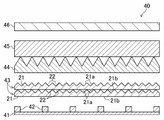
- the backlight unit 40 includes a reflective sheet 41, a plurality of light sources 42 arranged two-dimensionally on the reflective sheet 41, and a light diffusion sheet 43 provided above the plurality of light sources 42. , a first prism sheet 44 and a second prism sheet 45 provided in this order above the light diffusion sheet 43 , and a polarizing sheet 46 provided above the second prism sheet 45 .
- FIG. 2 illustrates a case where two layers of light diffusion sheets 43 having the same structure are laminated and provided in the backlight unit 40, but the light diffusion sheet 43 may be used in a single layer or in three layers. It may be used by laminating more than one layer.
- the reflective sheet 41 is composed of, for example, a white film made of polyethylene terephthalate resin, a silver-deposited film, or the like.
- the type of the light source 42 is not particularly limited, it may be, for example, an LED element, a laser element, or the like, and an LED element may be used from the viewpoint of cost, productivity, and the like.
- the light source 42 may have a rectangular shape when viewed from above, in which case the length of one side is 10 ⁇ m or more (preferably 50 ⁇ m or more) and 20 mm or less (preferably 10 mm or less, more preferably 5 mm or less). There may be.
- LEDs are used as the light source 42, a plurality of LED chips may be arranged on the reflective sheet 41 at regular intervals.
- a lens may be attached to the LED in order to adjust the light emission angle characteristics of the LED serving as the light source 42 .
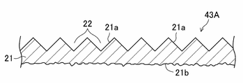
- the light diffusion sheet 43 has a base material layer 21, as shown in FIGS.
- the base material layer 21 is configured using, for example, clear polycarbonate as a base material (matrix resin). Base material layer 21 does not substantially contain a diffusing agent.
- the light diffusion sheet 43 (base material layer 21) has a first surface 21a that serves as a light emitting surface and a second surface 21b that serves as a light incident surface. That is, the light diffusion sheet 43 is arranged with the second surface 21 b facing the light source 42 .
- a plurality of concave portions 22 having a substantially inverted polygonal pyramid shape, for example, a substantially inverted quadrangular pyramid shape (inverted pyramid shape) are arranged two-dimensionally.
- the arithmetic average roughness of the second surface 21b of the light diffusion sheet 43 is 3.0 ⁇ m or less.
- the internal haze of the light diffusion sheet 43 is 1.5% or less.
- the term "internal haze” means haze excluding the surface haze caused by the surface shape (specifically, the concave portions 22 of the first surface 21a) among the total haze.
- the apex angle ⁇ of the concave portions 22 is 80° or more and 100° or less, for example, 90°, and the arrangement pitch p of the concave portions 22 is, for example, about 100 ⁇ m.
- the apex angle ⁇ of the concave portion 22 is a plane (longitudinal section) perpendicular to the second surface 21b (horizontal plane) of the light diffusion sheet 43 and passes through the vertex of the inverted polygonal pyramid and faces the vertex.
- the arrangement pitch p of the concave portions 22 is the horizontal distance between the vertices of the inverted polygonal pyramids in the adjacent concave portions 22 (the distance along the direction parallel to the second surface 21b).
- the light diffusion sheet 43 has a single-layer structure of the base material layer 21 having an uneven shape (recesses 22) on the first surface 21a.
- the light diffusing sheet 43 may be configured with a two-layer structure of a substrate layer having flat surfaces on both sides and a layer having an uneven surface on one surface, or may have an uneven surface on one surface. It may be configured with a structure of three or more layers including layers.
- the recesses 22 having an inverted pyramid shape are arranged two-dimensionally to form an uneven shape on the first surface 21a.
- the recesses 22 may be arranged randomly to the extent that the effects of the present invention are not lost.
- the term “substantially inverted polygonal pyramid” in consideration of the fact that it is difficult to form a geometrically strict inverted polygonal pyramid recess using a normal shape transfer technique, the term “substantially inverted polygonal pyramid” is used, but “substantially "Inverted polygonal pyramid” shall include shapes that can be regarded as true or substantially inverted polygonal pyramids. Further, the word “substantially” means that it can be approximated, and for example, "substantially inverted quadrangular pyramid” means a shape that can be approximated to an inverted quadrangular pyramid.
- an "inverted polygonal truncated pyramid” with a flat top is also included in the “substantially inverted polygonal pyramid” if the top area is small to the extent that the effects of the present invention are not lost.
- the “substantially inverted polygonal pyramid” also includes a shape deformed from the “inverted polygonal pyramid” within the range of unavoidable variation in shape due to the processing accuracy in industrial production.
- the "inverted polygonal pyramid" shape of the concave portion 22 a triangular pyramid, a square pyramid, or a hexagonal pyramid that can be two-dimensionally arranged without gaps is preferable.
- An inverted quadrangular pyramid may be selected as the "inverted polygonal pyramid" in consideration of the accuracy of the surface cutting work of the mold (metal roll) used in the manufacturing process such as extrusion molding and injection molding when providing the recess 22. .
- the recesses 22 may be provided without gaps on the first surface 21a, or may be provided at predetermined intervals.
- the first prism sheet 44 and the second prism sheet 45 are formed, for example, so that a plurality of grooves having an isosceles triangular cross section are adjacent to each other, and the apex angle of the prism sandwiched between a pair of adjacent grooves is It is a film formed at an angle of about 90°.
- Each groove formed in the first prism sheet 44 and each groove formed in the second prism sheet 45 are arranged so as to be orthogonal to each other.
- the first prism sheet 44 and the second prism sheet 45 may be integrally formed.
- PET polyethylene terephthalate
- the first prism sheet 44 and the second prism sheet 45 for example, PET (polyethylene terephthalate) film may be formed into a prism shape using a UV curable acrylic resin.
- polarizing sheet 46 for example, DBEF series manufactured by 3M may be used.
- the polarizing sheet 46 prevents the light emitted from the backlight unit 40 from being absorbed by the first polarizing plate 6 of the liquid crystal display device 50, thereby improving the brightness of the display screen 50a.
- the first surface 21a which is the light exit surface
- the second surface 21b which is the light incident surface
- the high-intensity light traveling straight from the light source 42 toward the light diffusion sheet 43 can be uniformly diffused by the concave portions 22 of the first surface 21a, thereby eliminating the image of the light source 42 on the display screen 50a.
- In-plane luminance uniformity can be improved. Therefore, it is possible to cope with further thinning and reduction of the number of light sources.
- FIG. 4 shows a cross-sectional configuration of a light diffusion sheet 43A of a comparative example in which uneven shapes are provided on the second surface 21b by embossing. 4, the same components as those of the light diffusion sheet 43 of the present embodiment shown in FIG. 3 are denoted by the same reference numerals.
- the light diffusion sheet 43A of the comparative example the light coming straight from the light source 42 is randomly diffused by the second surface 21b, so the light cannot be uniformly diffused by the concave portions 22 of the first surface 21a.
- the degree to which the image of the light source 42 is eliminated differs depending on the position of the light source 42 on the first surface 21a. As a result, there arises a problem that the in-plane luminance uniformity deteriorates.
- the arithmetic average roughness of the second surface 21b which is the light incident surface, is set to 3.0 ⁇ m or less.
- the arithmetic average roughness of the second surface 21b of the light diffusion sheet 43 is preferably 0.5 ⁇ m or less, more preferably 0.3 ⁇ m or less. It is more preferably 0.1 ⁇ m or less, and even more preferably 0.05 ⁇ m or less.
- the arithmetic average roughness of the second surface 21b of the light diffusion sheet 43 is preferably 0.1 ⁇ m or more, more preferably 0.5 ⁇ m or more. It is more preferably 0 ⁇ m or more.
- the problem of deterioration of in-plane luminance uniformity also occurs when fine particles (diffusing agent) having a refractive index different from that of the base layer 21 are dispersed in the base layer 21 to diffuse light. That is, in the light diffusion sheet 43 of the present embodiment, the content of the diffusing agent, that is, the internal haze, is preferably as small as possible. Specifically, the internal haze of the light diffusion sheet 43 is preferably 5% or less, more preferably 3% or less, more preferably 1.5% or less, and 1.0% or less. is even more preferable.
- the concave portions 22 when the concave portions 22 are formed in a substantially inverted quadrangular pyramid shape, the light traveling straight from the light source 42 can be uniformly diffused on the first surface 21a.
- the apex angle of the concave portions 22 is 80° or more and 100° or less, light coming straight from the light source 42 can be uniformly diffused on the first surface 21a.
- the backlight unit 40 of this embodiment is incorporated in the liquid crystal display device 50, and guides the light emitted from the plurality of light sources 42 to the display screen 50a side.
- the light diffusion sheet 43 of the present embodiment is arranged between the display screen 50 a and the light source 42 with the second surface 21 b facing the light source 42 . Therefore, the light diffusing sheet 43 can improve the in-plane brightness uniformity, so that it is possible to further reduce the thickness and reduce the number of light sources.
- the light source 42 may be arranged on the reflection sheet 41 provided on the opposite side of the display screen 50a when viewed from the light diffusion sheet 43. By doing so, the light is further diffused by multiple reflections between the light diffusion sheet 43 and the reflection sheet 41, so that the in-plane luminance uniformity is further improved.
- a plurality of light diffusion sheets 43 may be laminated and arranged between the display screen 50a and the light source 42 . With this configuration, the light coming straight from the light source 42 is repeatedly diffused by the first surface 21a of each light diffusion sheet 43, so that the in-plane luminance uniformity is further improved.
- the diffusion performance of the light diffusion sheet 43 suppresses the deterioration of the in-plane luminance uniformity more than before. can do.
- the liquid crystal display device 50 of this embodiment includes the backlight unit 40 of this embodiment and the liquid crystal display panel 5 . Therefore, the backlight unit 40 can improve the in-plane luminance uniformity, so that it is possible to further reduce the thickness and reduce the number of light sources. Similar effects can be obtained in information equipment (personal computers, mobile phones, etc.) in which the liquid crystal display device 50 of the present embodiment is incorporated.
- the number of light sources 42 to be arranged is not particularly limited. Arranging regularly means arranging with a certain rule, and for example, the case where the light sources 42 are arranged at regular intervals corresponds to this.
- the center-to-center distance between two adjacent light sources 42 may be 0.5 mm or more (preferably 2 mm or more) and 20 mm or less.
- the light diffusion sheet 43 may contain a diffusing agent and other additives as long as the effects of the present invention are not lost.
- Additives that can be contained are not particularly limited, but may be, for example, inorganic particles such as silica, titanium oxide, aluminum hydroxide, barium sulfate, etc.; They may be organic particles.
- the resin that forms the matrix of the base layer 21 is not particularly limited as long as it is made of a material that allows light to pass through.
- Polymerization resin, polyethylene terephthalate, polyethylene naphthalate, cellulose acetate, polyimide, and the like.
- the thickness of the light diffusion sheet 43 is not particularly limited. may be When the thickness of the light diffusion sheet 43 exceeds 3 mm, it becomes difficult to achieve thinning of the liquid crystal display. On the other hand, when the thickness of the light diffusing sheet 43 is less than 0.1 mm, it becomes difficult to exhibit the aforementioned effect of improving the brightness uniformity.
- the light diffusion sheet 43 may be film-like or plate-like.
- the method of manufacturing the light diffusion sheet 43 is not particularly limited, but for example, an extrusion molding method, an injection molding method, or the like may be used.
- the procedure for manufacturing a single-layer light diffusion sheet having an uneven surface using an extrusion molding method is as follows. First, pellet-shaped plastic particles (which may contain a diffusing agent) are put into a single-screw extruder, melted and kneaded while being heated. After that, the molten resin extruded by the T-die is sandwiched between two metal rolls, cooled, transported using guide rolls, and cut into flat plates by a sheet cutter to produce a light diffusion sheet. .
- the reverse shape of the roll surface is transferred to the resin. can be shaped into
- the shape transferred to the resin does not always correspond to the shape of the roll surface that is 100% transferred, the shape of the roll surface may be designed by calculating backward from the degree of transfer.
- pellet-shaped plastic particles necessary for forming each layer are supplied to each of two single-screw extruders. After charging, the same procedure as described above is performed for each layer, and each sheet thus produced may be laminated.
- a diffusion sheet with a two-layer structure having an uneven surface may be produced as follows. First, pellet-like plastic particles necessary for forming each layer are put into each of two single-screw extruders, melted and kneaded while being heated. After that, the molten resin for each layer is put into one T-die, laminated in the T-die, and the laminated molten resin extruded by the T-die is sandwiched between two metal rolls and cooled. After that, the laminated molten resin may be conveyed using guide rolls and cut into flat plates with a sheet cutter to produce a diffusion sheet having a two-layer structure having an uneven surface.
- the light diffusion sheet 43 may be manufactured as follows by shape transfer using UV (ultraviolet). First, a roll having an inverted shape of the uneven shape to be transferred is filled with an uncured UV curable resin, and the substrate is pressed against the resin. Next, in a state in which the roll filled with the ultraviolet curable resin and the substrate are integrated, the resin is cured by irradiating ultraviolet rays. Next, the sheet on which the concavo-convex shape has been shape-transferred by the resin is separated from the roll. Finally, the sheet is again irradiated with ultraviolet rays to completely harden the resin, thereby producing a light diffusion sheet having an uneven surface.
- UV ultraviolet
- the backlight unit 40 a direct type backlight unit in which a plurality of light sources 42 are dispersedly arranged on the back side of the display screen 50a of the liquid crystal display device 50 is used. Therefore, in order to miniaturize the liquid crystal display device 50, it is necessary to reduce the distance between the light source 42 and the light diffusion sheet 43. FIG. However, when this distance is reduced, a phenomenon (brightness unevenness) is likely to occur in which the brightness of the display screen 50a in the portion located on the area between the light sources 42 dispersedly arranged is lower than that in the other portions.
- the distance between the light source and the light diffusion sheet is set to 15 mm or less, preferably 10 mm or less, more preferably 5 mm or less, further preferably 2 mm or less, and ultimately 0 mm.
- the usefulness of the present invention is considered to be even more pronounced.
- a light diffusion sheet having a base layer with a thickness of 130 ⁇ m and using clear polycarbonate as a base material was used in the examples and comparative examples.
- a plurality of approximately inverted quadrangular pyramid-shaped (inverted pyramid-shaped) recesses having an apex angle of 90° were two-dimensionally arranged at a pitch of 100 ⁇ m on the first surface (light emission surface) of the light diffusion sheet.
- four types of light diffusion sheets having second surfaces (light incident surfaces) processed to have arithmetic average roughness Ra of 2.6 ⁇ m, 1.8 ⁇ m, 1.2 ⁇ m, and 0.03 ⁇ m were used.
- a light diffusion sheet having a second surface (light incident surface) processed to have an arithmetic mean roughness Ra of 3.4 ⁇ m was prepared.
- the manufacturing method of the light diffusion sheet of the example is as follows. First, a pellet-shaped base material resin (plastic resin) was made into a resin film by an extruder. After that, a roll with a convex pyramid shape is used as one of the two metal rolls, and a mirror surface roll is used as the other roll. , and a single-layer light diffusion sheet having a mirror surface on the other side.
- a pellet-shaped base material resin plastic resin
- the manufacturing method of the light diffusion sheet of the comparative example is as follows. First, a pellet-shaped base material resin (plastic resin) was made into a resin film by an extruder. After that, one of the two metal rolls is a roll having a convex pyramid shape on the surface, and the other roll is an embossing roll having a random mat shape, and both rolls are pressed against the resin film. A single-layer light diffusion sheet having an inverted pyramid shape on one side and an embossed shape on the other side was fabricated. The difference in roughness of the embossed surface was controlled by the roughness of the embossing roll surface.
- the surface roughness (arithmetic mean roughness Ra) of the light diffusion sheets of Examples and Comparative Examples was measured using SJ-210 manufactured by Mitutoyo, in accordance with JIS B 0601-1994, at a measurement speed of 0.5 mm/s. , the measurement distance was set to 4 mm, and the cutoff value ⁇ c was set to 0.8 mm.
- the internal haze and total light transmittance of the light diffusion sheet of Example were 0.6% and 90.8%, respectively.
- the internal haze and total light transmittance were measured by filling the depressions (inverted pyramids) on the first surface of the light diffusion sheet with a UV curable resin (the same resin as the matrix resin of the light diffusion sheet).
- a resin having the same refractive index as the matrix resin of the light diffusion sheet was used as the UV curable resin.
- the internal haze and total light transmittance were measured using a haze meter HZ-2 manufactured by Suga Test Instruments Co., Ltd. in accordance with JIS K 7136.
- the in-plane luminance uniformity of the light diffusion sheets of Examples and Comparative Examples was evaluated as follows. First, on a blue LED array arranged at a pitch of 2.8 mm, two or three light diffusion sheets of Examples (4 types) and Comparative Example are laminated and placed, and two prism sheets are placed thereon. In addition, a transparent glass plate is placed on top of it to prevent the sheets from floating, and a two-dimensional color luminance meter UA-200 manufactured by Topcon Technohouse Co., Ltd. is used to measure the vertical direction upward (from the LED array to the glass plate). direction) was measured. Next, the obtained two-dimensional luminance distribution image is corrected for variations in the emission intensity of individual LEDs, and filtered to suppress bright and dark point noise caused by foreign matter.
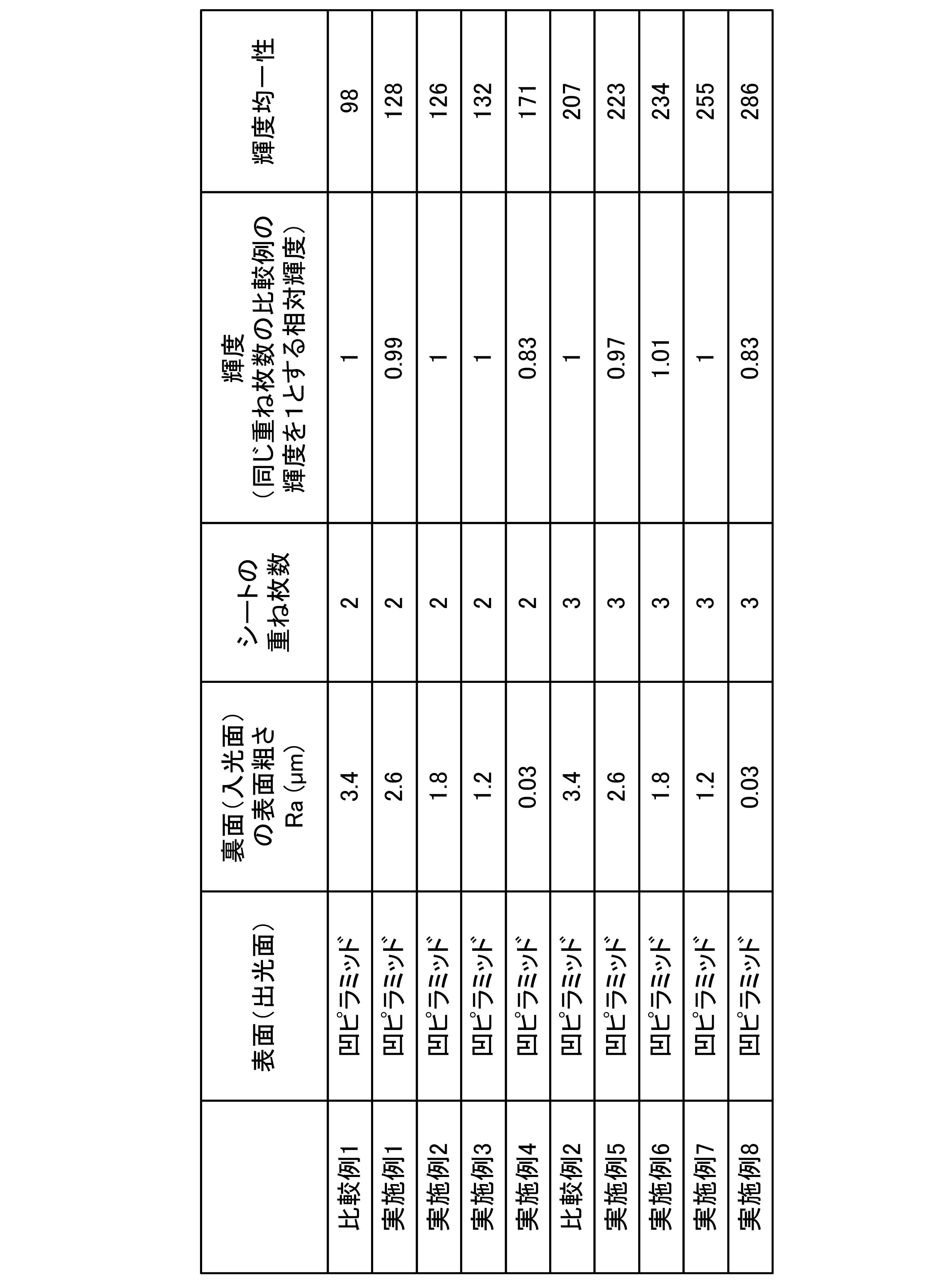
- Table 1 shows the evaluation results of luminance and in-plane luminance uniformity of the light diffusion sheets of Examples and Comparative Examples.
- the luminance shown in Table 1 is a relative luminance with the luminance (average value) of the comparative example having the same number of superimposed sheets set to 1.
- Examples 1 to 4 have the second surface (light incident surface) processed so that the arithmetic mean roughness Ra is 2.6 ⁇ m, 1.8 ⁇ m, 1.2 ⁇ m, and 0.03 ⁇ m. This is the result of evaluating luminance and in-plane luminance uniformity by stacking two light diffusion sheets of the above-described example.
- Comparative Example 1 two light diffusion sheets of the aforementioned Comparative Example having the second surface processed so as to have an arithmetic mean roughness Ra of 3.4 ⁇ m were superimposed, and luminance and in-plane luminance uniformity were measured. This is the result of evaluation.
- Examples 5 to 8 have the second surface processed so that the arithmetic mean roughness Ra is 2.6 ⁇ m, 1.8 ⁇ m, 1.2 ⁇ m, and 0.03 ⁇ m, respectively. This is the result of evaluating luminance and in-plane luminance uniformity by stacking three sheets.
- Comparative Example 2 three light diffusion sheets of the above Comparative Example having the second surface processed so as to have an arithmetic mean roughness Ra of 3.4 ⁇ m were stacked, and luminance and in-plane luminance uniformity were measured. This is the result of evaluation.
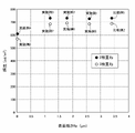
- FIG. 5 shows the relationship between the surface roughness (arithmetic mean roughness) Ra of the light incident surface of the light diffusion sheet and the in-plane luminance uniformity in Examples 1 to 8 and Comparative Examples 1 and 2, respectively.
- FIG. 6 shows the relationship between the surface roughness (arithmetic mean roughness) Ra of the light incident surface of the light diffusion sheet and the luminance in Examples 1 to 8 and Comparative Examples 1 and 2, respectively.
- the in-plane luminance uniformity improved as the surface roughness Ra of the light incident surface decreased.
- the light incident surface had the smallest surface roughness Ra of 0.03 ⁇ m (mirror surface) (Examples 4 and 8)
- the in-plane luminance uniformity was maximized for each number of layers.
- the surface roughness Ra of the light incident surface was 3.0 ⁇ m or less, the deterioration of the in-plane luminance uniformity compared to the mirror surface was suppressed for each number of stacked layers.
- the surface roughness Ra of the light incident surface of the light diffusion sheet may be set to 0.1 ⁇ m or less.
- the surface roughness Ra of the light incident surface of the light diffusion sheet may be set to 1.0 ⁇ m or more and 3.0 ⁇ m or less.
Abstract
Description
以下、実施形態に係る光拡散シート、バックライトユニット、液晶表示装置及び情報機器について、図面を参照しながら説明する。尚、本開示の範囲は、以下の実施の形態に限定されず、本開示の技術的思想の範囲内で任意に変更可能である。 (embodiment)
Hereinafter, a light diffusion sheet, a backlight unit, a liquid crystal display device, and an information device according to embodiments will be described with reference to the drawings. Note that the scope of the present disclosure is not limited to the following embodiments, and can be arbitrarily changed within the scope of the technical ideas of the present disclosure.
以下、実施例及び比較例について説明する。 (Examples and Comparative Examples)
Examples and comparative examples are described below.
2 CF基板
3 液晶層
5 液晶表示パネル
6 第1偏光板
7 第2偏光板
21 基材層
21a 第1面
21b 第2面
22 凹部
40 バックライトユニット
41 反射シート
42 光源
43 光拡散シート
44 第1プリズムシート
45 第2プリズムシート
46 偏光シート
50 液晶表示装置
50a 表示画面 REFERENCE SIGNS
Claims (10)
- 光出射面となる第1面と、光入射面となる第2面とを有する光拡散シートであって、
前記第1面には、略逆多角錐状の複数の凹部が設けられ、
前記第2面は、算術平均粗さが0.1μm以下の平坦面であり、
内部ヘイズが1.5%以下である
光拡散シート。 A light diffusion sheet having a first surface serving as a light emitting surface and a second surface serving as a light incident surface,
The first surface is provided with a plurality of substantially inverted polygonal pyramid-shaped recesses,
The second surface is a flat surface having an arithmetic mean roughness of 0.1 μm or less,
A light diffusion sheet having an internal haze of 1.5% or less. - 光出射面となる第1面と、光入射面となる第2面とを有する光拡散シートであって、
前記第1面には、略逆多角錐状の複数の凹部が設けられ、
前記第2面の算術平均粗さは、1.0μm以上3.0μm以下であり、
内部ヘイズが1.5%以下である
光拡散シート。 A light diffusion sheet having a first surface serving as a light emitting surface and a second surface serving as a light incident surface,
The first surface is provided with a plurality of substantially inverted polygonal pyramid-shaped recesses,
The arithmetic mean roughness of the second surface is 1.0 μm or more and 3.0 μm or less,
A light diffusion sheet having an internal haze of 1.5% or less. - 前記複数の凹部は、略逆四角錐状に形成される
請求項1又は2に記載の光拡散シート。 3. The light diffusion sheet according to claim 1, wherein the plurality of concave portions are formed in a substantially inverted quadrangular pyramid shape. - 前記複数の凹部の頂角は、80°以上100°以下である
請求項1~3のいずれか1項に記載の光拡散シート。 The light diffusion sheet according to any one of claims 1 to 3, wherein the apex angles of the plurality of concave portions are 80° or more and 100° or less. - 液晶表示装置に組み込まれ、複数の光源から発せられた光を表示画面側に導くバックライトユニットであって、
前記表示画面と前記複数の光源との間に、請求項1~4のいずれか1項に記載の光拡散シートを備え、
前記光拡散シートは、前記第2面を前記複数の光源の方に向けて配置される
バックライトユニット。 A backlight unit that is incorporated in a liquid crystal display device and guides light emitted from a plurality of light sources to a display screen side,
The light diffusion sheet according to any one of claims 1 to 4 is provided between the display screen and the plurality of light sources,
The light diffusion sheet is a backlight unit arranged with the second surface facing the plurality of light sources. - 前記複数の光源は、前記光拡散シートから見て前記表示画面の反対側に設けられた反射シートの上に配置される
請求項5に記載のバックライトユニット。 6. The backlight unit according to claim 5, wherein the plurality of light sources are arranged on a reflective sheet provided on the opposite side of the display screen when viewed from the light diffusion sheet. - 前記光拡散シートは、複数枚積層して前記表示画面と前記複数の光源との間に配置される
請求項5又は6に記載のバックライトユニット。 7. The backlight unit according to claim 5, wherein a plurality of said light diffusion sheets are laminated and arranged between said display screen and said plurality of light sources. - 前記複数の光源と前記光拡散シートとの間の距離は、10mm以下である
請求項5~7のいずれか1項に記載のバックライトユニット。 8. The backlight unit according to claim 5, wherein the distance between the plurality of light sources and the light diffusion sheet is 10 mm or less. - 請求項5~8のいずれか1項に記載のバックライトユニットと、
液晶表示パネルとを備える
液晶表示装置。 a backlight unit according to any one of claims 5 to 8;
A liquid crystal display device comprising a liquid crystal display panel. - 請求項9に記載の液晶表示装置を備える情報機器。 An information device comprising the liquid crystal display device according to claim 9.
Priority Applications (4)
| Application Number | Priority Date | Filing Date | Title |
|---|---|---|---|
| CN202280020373.8A CN116964492A (en) | 2021-03-19 | 2022-02-04 | Light diffusion sheet, backlight unit, liquid crystal display device, and information apparatus |
| KR1020237029715A KR20230132875A (en) | 2021-03-19 | 2022-02-04 | Light diffusion sheets, backlight units, liquid crystal displays and information devices |
| EP22770922.7A EP4296728A1 (en) | 2021-03-19 | 2022-02-04 | Light diffusion sheet, backlight unit, liquid crystal display device, and information equipment |
| US18/467,174 US20240012286A1 (en) | 2021-03-19 | 2023-09-14 | Light diffusion sheet, backlight unit, liquid crystal display device, and information equipment |
Applications Claiming Priority (4)
| Application Number | Priority Date | Filing Date | Title |
|---|---|---|---|
| JP2021045467A JP2022144447A (en) | 2021-03-19 | 2021-03-19 | Light diffusion sheet, backlight unit, liquid crystal display device, and information device |
| JP2021-045467 | 2021-03-19 | ||
| JP2022-015101 | 2022-02-02 | ||
| JP2022015101A JP2023113017A (en) | 2022-02-02 | 2022-02-02 | Light diffusion sheet, backlight unit, liquid crystal display, and information instrument |
Related Child Applications (1)
| Application Number | Title | Priority Date | Filing Date |
|---|---|---|---|
| US18/467,174 Continuation US20240012286A1 (en) | 2021-03-19 | 2023-09-14 | Light diffusion sheet, backlight unit, liquid crystal display device, and information equipment |
Publications (1)
| Publication Number | Publication Date |
|---|---|
| WO2022196162A1 true WO2022196162A1 (en) | 2022-09-22 |
Family
ID=83322211
Family Applications (1)
| Application Number | Title | Priority Date | Filing Date |
|---|---|---|---|
| PCT/JP2022/004369 WO2022196162A1 (en) | 2021-03-19 | 2022-02-04 | Light diffusion sheet, backlight unit, liquid crystal display device, and information equipment |
Country Status (5)
| Country | Link |
|---|---|
| US (1) | US20240012286A1 (en) |
| EP (1) | EP4296728A1 (en) |
| KR (1) | KR20230132875A (en) |
| TW (1) | TWI799166B (en) |
| WO (1) | WO2022196162A1 (en) |
Citations (4)
| Publication number | Priority date | Publication date | Assignee | Title |
|---|---|---|---|---|
| JP2011129277A (en) | 2009-12-15 | 2011-06-30 | Toppan Printing Co Ltd | Backlight unit and display device |
| JP2012114003A (en) * | 2010-11-25 | 2012-06-14 | Nippon Shokubai Co Ltd | Optical member and planar light source device using the optical member |
| JP2014059525A (en) * | 2012-09-19 | 2014-04-03 | Oki Electric Ind Co Ltd | Device and metho for band expansion |
| JP2020086432A (en) * | 2018-11-16 | 2020-06-04 | 恵和株式会社 | Optical sheet, backlight unit, liquid crystal display apparatus, and information device |
Family Cites Families (3)
| Publication number | Priority date | Publication date | Assignee | Title |
|---|---|---|---|---|
| KR102075998B1 (en) * | 2017-05-29 | 2020-05-18 | 주식회사 엘엠에스 | Light Guide Unit Having Shielding Portion, Backlight Module Using The Same and Manufacturing Method of Light Guide Unit |
| CN111788264B (en) * | 2018-02-27 | 2022-12-16 | 株式会社钟化 | Resin composition and liquid for film production based on solution casting method |
| WO2021011410A1 (en) * | 2019-07-12 | 2021-01-21 | Magic Leap, Inc. | Methods and systems for augmented reality display with dynamic field of view |
-
2022
- 2022-02-04 EP EP22770922.7A patent/EP4296728A1/en active Pending
- 2022-02-04 WO PCT/JP2022/004369 patent/WO2022196162A1/en active Application Filing
- 2022-02-04 KR KR1020237029715A patent/KR20230132875A/en unknown
- 2022-03-04 TW TW111107885A patent/TWI799166B/en active
-
2023
- 2023-09-14 US US18/467,174 patent/US20240012286A1/en active Pending
Patent Citations (4)
| Publication number | Priority date | Publication date | Assignee | Title |
|---|---|---|---|---|
| JP2011129277A (en) | 2009-12-15 | 2011-06-30 | Toppan Printing Co Ltd | Backlight unit and display device |
| JP2012114003A (en) * | 2010-11-25 | 2012-06-14 | Nippon Shokubai Co Ltd | Optical member and planar light source device using the optical member |
| JP2014059525A (en) * | 2012-09-19 | 2014-04-03 | Oki Electric Ind Co Ltd | Device and metho for band expansion |
| JP2020086432A (en) * | 2018-11-16 | 2020-06-04 | 恵和株式会社 | Optical sheet, backlight unit, liquid crystal display apparatus, and information device |
Also Published As
| Publication number | Publication date |
|---|---|
| US20240012286A1 (en) | 2024-01-11 |
| TW202238234A (en) | 2022-10-01 |
| EP4296728A1 (en) | 2023-12-27 |
| KR20230132875A (en) | 2023-09-18 |
| TWI799166B (en) | 2023-04-11 |
Similar Documents
| Publication | Publication Date | Title |
|---|---|---|
| JP6683872B1 (en) | Optical sheet, backlight unit, liquid crystal display device, and information device | |
| WO2021199741A1 (en) | Optical sheet, backlight unit, liquid crystal display apparatus, and information device | |
| WO2023007917A1 (en) | Optical sheet laminate, backlight unit, liquid crystal display device, and information apparatus | |
| WO2022118533A1 (en) | Light diffusion sheet, backlight unit, liquid crystal display device, information apparatus, and method for manufacturing light diffusion sheet | |
| JP7037624B2 (en) | Optical sheet, backlight unit, liquid crystal display device and information equipment | |
| WO2022196162A1 (en) | Light diffusion sheet, backlight unit, liquid crystal display device, and information equipment | |
| JP2023113017A (en) | Light diffusion sheet, backlight unit, liquid crystal display, and information instrument | |
| JP2022144447A (en) | Light diffusion sheet, backlight unit, liquid crystal display device, and information device | |
| WO2023145199A1 (en) | Optical sheet laminate, backlight unit, liquid crystal display device, information equipment, and production method for backlight unit | |
| WO2023282055A1 (en) | Optical sheet laminate, backlight unit, liquid crystal display device, information equipment, and production method for backlight unit | |
| JP7289001B2 (en) | Optical sheet laminate, backlight unit, liquid crystal display device, information equipment, and method for manufacturing backlight unit | |
| WO2023282054A1 (en) | Optical sheet laminate, backlight unit, liquid crystal display device, information equipment, and production method for backlight unit | |
| WO2023037651A1 (en) | Optical sheet laminate, backlight unit, liquid crystal display device, information equipment, and production method for backlight unit | |
| JP7275341B1 (en) | Light diffusion sheet, backlight unit, liquid crystal display device, information equipment, and method for manufacturing backlight unit | |
| WO2022250006A1 (en) | Light diffusion sheet, backlight unit, liquid crystal display device and information device | |
| TW202403355A (en) | Light diffusion sheet, backlight unit, liquid crystal display apparatus, information device, and method of manufacturing light diffusion sheet | |
| JP2022183047A (en) | Light diffusion sheet, backlight unit, liquid crystal display device, and information device | |
| TW202336513A (en) | Combined light diffusion sheet, backlight unit, liquid crystal display device, and information equipment | |
| CN116547473A (en) | Light diffusion sheet, backlight unit, liquid crystal display device, information apparatus, and method for manufacturing light diffusion sheet |
Legal Events
| Date | Code | Title | Description |
|---|---|---|---|
| 121 | Ep: the epo has been informed by wipo that ep was designated in this application |
Ref document number: 22770922 Country of ref document: EP Kind code of ref document: A1 |
|
| ENP | Entry into the national phase |
Ref document number: 20237029715 Country of ref document: KR Kind code of ref document: A |
|
| WWE | Wipo information: entry into national phase |
Ref document number: 202280020373.8 Country of ref document: CN |
|
| WWE | Wipo information: entry into national phase |
Ref document number: 2022770922 Country of ref document: EP |
|
| ENP | Entry into the national phase |
Ref document number: 2022770922 Country of ref document: EP Effective date: 20230919 |
|
| NENP | Non-entry into the national phase |
Ref country code: DE |