WO2022196102A1 - 制御装置、プログラム、及び制御方法 - Google Patents
制御装置、プログラム、及び制御方法 Download PDFInfo
- Publication number
- WO2022196102A1 WO2022196102A1 PCT/JP2022/002430 JP2022002430W WO2022196102A1 WO 2022196102 A1 WO2022196102 A1 WO 2022196102A1 JP 2022002430 W JP2022002430 W JP 2022002430W WO 2022196102 A1 WO2022196102 A1 WO 2022196102A1
- Authority
- WO
- WIPO (PCT)
- Prior art keywords
- space
- information
- control
- identification information
- unit
- Prior art date
- Legal status (The legal status is an assumption and is not a legal conclusion. Google has not performed a legal analysis and makes no representation as to the accuracy of the status listed.)
- Ceased
Links
Images






Classifications
-
- H—ELECTRICITY
- H04—ELECTRIC COMMUNICATION TECHNIQUE
- H04L—TRANSMISSION OF DIGITAL INFORMATION, e.g. TELEGRAPHIC COMMUNICATION
- H04L12/00—Data switching networks
- H04L12/28—Data switching networks characterised by path configuration, e.g. LAN [Local Area Networks] or WAN [Wide Area Networks]
- H04L12/2803—Home automation networks
- H04L12/2807—Exchanging configuration information on appliance services in a home automation network
- H04L12/2809—Exchanging configuration information on appliance services in a home automation network indicating that an appliance service is present in a home automation network
-
- H—ELECTRICITY
- H04—ELECTRIC COMMUNICATION TECHNIQUE
- H04L—TRANSMISSION OF DIGITAL INFORMATION, e.g. TELEGRAPHIC COMMUNICATION
- H04L12/00—Data switching networks
- H04L12/28—Data switching networks characterised by path configuration, e.g. LAN [Local Area Networks] or WAN [Wide Area Networks]
- H04L12/2803—Home automation networks
- H04L12/2816—Controlling appliance services of a home automation network by calling their functionalities
- H04L12/282—Controlling appliance services of a home automation network by calling their functionalities based on user interaction within the home
-
- H—ELECTRICITY
- H04—ELECTRIC COMMUNICATION TECHNIQUE
- H04Q—SELECTING
- H04Q9/00—Arrangements in telecontrol or telemetry systems for selectively calling a substation from a main station, in which substation desired apparatus is selected for applying a control signal thereto or for obtaining measured values therefrom
-
- H—ELECTRICITY
- H04—ELECTRIC COMMUNICATION TECHNIQUE
- H04L—TRANSMISSION OF DIGITAL INFORMATION, e.g. TELEGRAPHIC COMMUNICATION
- H04L12/00—Data switching networks
- H04L12/28—Data switching networks characterised by path configuration, e.g. LAN [Local Area Networks] or WAN [Wide Area Networks]
- H04L12/2803—Home automation networks
- H04L2012/2847—Home automation networks characterised by the type of home appliance used
- H04L2012/285—Generic home appliances, e.g. refrigerators
Definitions
- the present disclosure relates to control devices, programs, and control methods.
- Patent Document 1 discloses a home controller for turning on or off a plurality of devices installed in a plurality of rooms in a house.
- the home controller disclosed in Patent Document 1 manages devices for each room in a house.
- An object of the present disclosure is to obtain a control device, a program, and a control method capable of executing optimal equipment control according to the location of the control device.
- a control device is a control device that controls a plurality of devices installed in a building having a plurality of first spaces, and includes an acquisition unit that acquires installation information and arrangement information, and a space generation a unit, a device control unit, and a notification unit, wherein the installation information includes identification information of each first space of the plurality of first spaces, and information on which of the plurality of devices is installed in each of the first spaces. and the arrangement information includes identification information of the control device and identification of a specific first space in which the control device is arranged among the plurality of first spaces.
- the space generation unit combines the two or more first spaces based on the arrangement information acquired by the acquisition unit to create a second space and the device control unit generates relationship information indicating a correspondence relationship between the identification information of the second space and the identification information of two or more devices installed in the second space among the plurality of devices.
- the notification unit generates collective control information for collectively controlling the two or more devices installed in the second space based on the relationship information generated by the device control unit, and the second At least one of individual control information for individually controlling the two or more devices installed in two spaces is notified.
- FIG. 1 is a diagram showing the overall configuration of a home control system according to an embodiment of the present disclosure
- FIG. It is a figure which shows the example of an apparatus. It is a figure which shows the example of the floor plan with which a smart home is provided. It is a figure which shows the 1st example of a system configuration.
- FIG. 10 is a diagram showing a second example of system configuration;
- 10 is a flowchart showing an example of specific processing for space generation;
- FIG. 10 is a flowchart showing an example of specific processing for space generation;
- FIG. 7 is a diagram showing an example of an operation screen displayed on the display unit regarding the first embodiment
- FIG. 7 is a diagram showing an example of an operation screen displayed on the display unit regarding the first embodiment
- FIG. 7 is a diagram showing an example of an operation screen displayed on the display unit regarding the first embodiment
- 4 is a flowchart showing a first example of switching conditions
- 9 is a flowchart showing a second example of switching conditions
- FIG. 10 is a diagram showing an example of an operation screen displayed on the display unit regarding the second embodiment
- FIG. 10 is a diagram showing an example of an operation screen displayed on the display unit regarding the second embodiment
- Patent Document 1 discloses a home controller for turning on or off a plurality of devices installed in a plurality of rooms in a house. The home controller manages devices for each room in a house.
- the home controller arranged near the entrance/exit of the activity space collectively displays the plurality of devices installed in the activity space.
- the devices installed around the home controller which are located in a place away from the entrance/exit of the activity space, collectively or individually.
- the present inventor sets a management unit for a plurality of devices based on the installation information of the plurality of devices and the arrangement information of the control device including the entrance correspondence information.
- the present disclosure was conceived based on the knowledge that the management unit of a plurality of devices can be optimally set according to the location of the device.
- a control device is a control device that controls a plurality of devices installed in a building having a plurality of first spaces, and includes an acquisition unit that acquires installation information and arrangement information, and a space generation a unit, a device control unit, and a notification unit, wherein the installation information includes identification information of each first space of the plurality of first spaces, and information on which of the plurality of devices is installed in each of the first spaces. and the arrangement information includes identification information of the control device and identification of a specific first space in which the control device is arranged among the plurality of first spaces.
- the space generation unit combines the two or more first spaces based on the arrangement information acquired by the acquisition unit to create a second space and the device control unit generates relationship information indicating a correspondence relationship between the identification information of the second space and the identification information of two or more devices installed in the second space among the plurality of devices.
- the reporting unit reports batch control information for collectively controlling the two or more devices installed in the second space based on the relationship information generated by the device control unit.
- the notification unit when the control device is compatible with the entrance, notifies collective control information for collectively controlling two or more devices installed in the second space. Therefore, the user can collectively control two or more devices installed in the second space by the control device arranged near the entrance, thereby improving the user's convenience.
- the device control unit may include identification information of the specific first space and two or more of the plurality of devices installed in the specific first space among the plurality of devices. Generates relationship information indicating a correspondence relationship with the identification information of the device, and the notifying unit, based on the relationship information generated by the device control unit, the two or more devices installed in the specific first space. Collective control information for collectively controlling devices is broadcast.
- the notification unit when the control device does not correspond to the entrance/exit, notifies collective control information for collectively controlling two or more devices installed in the specific first space. Therefore, the user can control only the equipment installed in the specific first space where the control device is arranged by the control device arranged away from the doorway, thereby improving user convenience. becomes possible.
- a detection unit that detects a person other than the operator of the control device in the second space is further provided, and when the detection unit detects the person, the device control unit detects the specific person. generating relationship information indicating a correspondence relationship between the identification information of the first space and the identification information of two or more devices installed in the specific first space among the plurality of devices; Control information for controlling the two or more devices installed in the specific first space is notified based on the relationship information generated by the device control unit.
- the notification unit when the detection unit detects a person, notifies control information for controlling two or more devices installed in the specific first space. Therefore, when a person other than the user is located in the second space, the user can control only the devices installed in the specific first space where the control device is arranged by the control device. , it is possible to improve user convenience.
- the device control unit selects the identification information of the specific first space and the specific first space among the plurality of devices. Generates relationship information indicating a correspondence relationship with the identification information of two or more installed devices, and the notification unit installs in the specific first space based on the relationship information generated by the device control unit It notifies control information for controlling the two or more devices that are connected to each other.
- the notification unit when the current time does not belong to the specified time period, notifies the control information for controlling two or more devices installed in the specific first space. Therefore, a time period in which residents frequently enter and leave a room is set in advance as a designated time period. Since only the devices installed in the specific first space can be controlled, it is possible to improve user convenience.
- the notification unit has a display unit, and the display unit includes identification information of the second space, identification information of each device of the two or more devices installed in the second space, An icon is displayed as the collective control information for collectively controlling the two or more devices.
- identification information for example, space name
- identification information for example, device name
- the two or more devices collectively By displaying the icons for control on the display unit, it is possible to provide a user interface that is easy for the user to understand and operate.
- the reporting unit further reports individual control information for individually controlling the two or more devices installed in the second space, based on the relationship information.
- the second space includes at least two of a living room, a dining room, and a kitchen.
- control device by introducing the control device according to this aspect to a house having a floor plan in which the living room, the dining room, and the kitchen are not partitioned by walls, the advantages of introducing the control device can be improved. becomes possible.
- a program comprises a computer installed in a control device that controls a plurality of devices installed in a building having a plurality of first spaces;
- the arrangement information includes identification information of the control device and the arrangement information of the control device among the plurality of first spaces. identification information of a specific first space in which the control device is connected, entrance correspondence information indicating whether or not the control device is compatible with an entrance, and entrance correspondence information indicating whether or not the control device is compatible with an entrance, and are combined if the control device is compatible with an entrance among the plurality of first spaces.
- the space generation means generates the two or more second spaces based on the arrangement information acquired by the acquisition means.
- a second space is generated by combining one space, and the device control means generates identification information of the second space and identification information of two or more devices installed in the second space among the plurality of devices. and the output means collectively controls the two or more devices installed in the second space based on the relationship information generated by the device control unit.
- the related information is output toward the notification unit that notifies the collective control information for the purpose.
- the notification unit when the control device is compatible with the entrance, notifies collective control information for collectively controlling two or more devices installed in the second space. Therefore, the user can collectively control two or more devices installed in the second space by the control device arranged near the entrance, thereby improving the user's convenience.
- a control method is a control method for controlling a plurality of devices installed in a building having a plurality of first spaces, wherein the installation information is the first space in each of the plurality of first spaces. including a correspondence relationship between identification information of one space and identification information of each device installed in each of the plurality of devices in the first space; Identification information of a specific first space in which the control device is arranged among the first spaces of, entrance correspondence information indicating whether or not the control device is compatible with an entrance, and among the plurality of first spaces Including a correspondence relationship with identification information of two or more first spaces to be combined when the control device is doorway compatible, and when the control device is doorway compatible, a computer based on the acquired arrangement information, A second space is generated by combining the two or more first spaces, and identification information of the second space and identification information of two or more devices installed in the second space among the plurality of devices.
- To the notification unit that generates relationship information indicating the correspondence relationship between and notifies collective control information for collectively controlling the two or more devices
- the notification unit when the control device is compatible with the entrance, notifies collective control information for collectively controlling two or more devices installed in the second space. Therefore, the user can collectively control two or more devices installed in the second space by the control device arranged near the entrance, thereby improving the user's convenience.
- a control device is a control device that controls a plurality of devices installed in a building having a plurality of first spaces, and includes an acquisition unit that acquires installation information and arrangement information, and a space generation a unit, a device control unit, and a notification unit, wherein the installation information includes identification information of each first space of the plurality of first spaces, and information on which of the plurality of devices is installed in each of the first spaces. and the arrangement information includes identification information of the control device and identification of a specific first space in which the control device is arranged among the plurality of first spaces.
- the space generation unit combines the two or more first spaces based on the arrangement information acquired by the acquisition unit to create a second space and the device control unit generates relationship information indicating a correspondence relationship between the identification information of the second space and the identification information of two or more devices installed in the second space among the plurality of devices.
- the notification unit notifies individual control information for individually controlling the two or more devices installed in the second space based on the relationship information generated by the device control unit.
- the notification unit when the control device is compatible with the entrance, notifies individual control information for individually controlling two or more devices installed in the second space. Therefore, the user can individually control two or more devices installed in the second space by using the control device arranged near the entrance, thereby improving convenience for the user.
- the device control unit may include identification information of the specific first space and two or more of the plurality of devices installed in the specific first space among the plurality of devices. Generates relationship information indicating a correspondence relationship with the identification information of the device, and the notifying unit, based on the relationship information generated by the device control unit, the two or more devices installed in the specific first space. Notifies individual control information for controlling devices individually.
- the notification unit when the control device does not correspond to the entrance/exit, notifies individual control information for individually controlling two or more devices installed in the specific first space. Therefore, the user can control only the equipment installed in the specific first space where the control device is arranged by the control device arranged away from the doorway, thereby improving user convenience. becomes possible.
- a detection unit that detects a person other than the operator of the control device in the second space is further provided, and when the detection unit detects the person, the device control unit detects the specific person. generating relationship information indicating a correspondence relationship between the identification information of the first space and the identification information of two or more devices installed in the specific first space among the plurality of devices; Control information for controlling the two or more devices installed in the specific first space is notified based on the relationship information generated by the device control unit.
- the notification unit when the detection unit detects a person, notifies control information for controlling two or more devices installed in the specific first space. Therefore, when a person other than the user is located in the second space, the user can control only the devices installed in the specific first space where the control device is arranged by the control device. , it is possible to improve user convenience.
- the device control unit selects the identification information of the specific first space and the specific first space among the plurality of devices. Generates relationship information indicating a correspondence relationship with the identification information of two or more installed devices, and the notification unit installs in the specific first space based on the relationship information generated by the device control unit It notifies control information for controlling the two or more devices that are connected to each other.
- the notification unit when the current time does not belong to the specified time period, notifies the control information for controlling two or more devices installed in the specific first space. Therefore, a time period in which residents frequently enter and leave a room is set in advance as a designated time period. Since only the devices installed in the specific first space can be controlled, it is possible to improve user convenience.
- the notification unit has a display unit, and the display unit includes identification information of the second space, identification information of each device of the two or more devices installed in the second space, An icon as the individual control information for individually controlling the two or more devices is displayed.
- the identification information (for example, space name) of the second space, the identification information (for example, device name) of two or more devices installed in the second space, and the two or more devices are individually controlled.
- a user interface that is easy for the user to understand and operate can be provided by displaying the icon for the operation on the display unit.
- the second space includes at least two of a living room, a dining room, and a kitchen.
- control device by introducing the control device according to this aspect to a house having a floor plan in which the living room, the dining room, and the kitchen are not partitioned by walls, the advantages of introducing the control device can be improved. becomes possible.
- a program comprises a computer installed in a control device that controls a plurality of devices installed in a building having a plurality of first spaces;
- the arrangement information includes identification information of the control device and the arrangement information of the control device among the plurality of first spaces. identification information of a specific first space in which the control device is connected, entrance correspondence information indicating whether or not the control device is compatible with an entrance, and entrance correspondence information indicating whether or not the control device is compatible with an entrance, and are combined if the control device is compatible with an entrance among the plurality of first spaces.
- the space generation means generates the two or more second spaces based on the arrangement information acquired by the acquisition means.
- a second space is generated by combining one space, and the device control means generates identification information of the second space and identification information of two or more devices installed in the second space among the plurality of devices. and the output means individually controls the two or more devices installed in the second space based on the relationship information generated by the device control unit.
- the related information is output to the notification unit that notifies the individual control information.
- the notification unit when the control device is compatible with the entrance, notifies individual control information for individually controlling two or more devices installed in the second space. Therefore, the user can individually control two or more devices installed in the second space by using the control device arranged near the entrance, thereby improving convenience for the user.
- a control method is a control method for controlling a plurality of devices installed in a building having a plurality of first spaces, wherein the installation information is the first space in each of the plurality of first spaces. including a correspondence relationship between identification information of one space and identification information of each device installed in each of the plurality of devices in the first space; Identification information of a specific first space in which the control device is arranged among the first spaces of, entrance correspondence information indicating whether or not the control device is compatible with an entrance, and among the plurality of first spaces Including a correspondence relationship with identification information of two or more first spaces to be combined when the control device is doorway compatible, and when the control device is doorway compatible, a computer based on the acquired arrangement information, A second space is generated by combining the two or more first spaces, and identification information of the second space and identification information of two or more devices installed in the second space among the plurality of devices.
- the notification unit when the control device is compatible with the entrance, notifies individual control information for individually controlling two or more devices installed in the second space. Therefore, the user can individually control two or more devices installed in the second space by using the control device arranged near the entrance, thereby improving convenience for the user.
- the present disclosure can also be implemented as a program that causes a computer to execute each characteristic configuration included in such a device, or as a system that operates with this program. It goes without saying that such a computer program can be distributed via a computer-readable non-temporary recording medium such as a CD-ROM or a communication network such as the Internet.
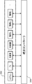
- FIG. 1 is a diagram showing the overall configuration of a home control system according to an embodiment of the present disclosure.
- the home control system comprises smart home 100 , communication network 500 and server 400 . Although only one smart home 100 is shown in FIG. 1 for simplification of explanation, a plurality of smart homes may be provided.
- the smart home 100 has multiple spaces (rooms, bathrooms, toilets, entrances, corridors, etc.) in which multiple devices 300 to be controlled are installed. Also, in the smart home 100, an integrated controller 200 for controlling the operations of these devices 300 is arranged. The integrated controller 200 can mutually perform data communication with each device 300 via any communication network such as a wireless LAN or a public line network.
- the server 400 is a control device for managing and controlling the entire home control system.
- Communication network 500 is any communication network such as a public switched telephone network.
- a server 400 , an integrated controller 200 and devices 300 are connected to the communication network 500 . This allows the server 400 to mutually perform data communication with the integrated controller 200 and the device 300 via the communication network 500 .
- FIG. 2 is a diagram showing an example of the device 300.
- the device 300 is any IoT device such as an air conditioner, TV, refrigerator, rice cooker, and lighting.
- Each device 300 is connected to the integrated controller 200 via a communication network.
- FIG. 3 is a diagram showing an example of the layout of the living room 151, dining room 152, and kitchen 153 included in the smart home 100.
- FIG. 3 there are no walls between the living room 151 , dining room 152 , and kitchen 153 , and these multiple rooms can be used as one activity space called living dining kitchen (LDK) 150 .
- LLK living dining kitchen
- a doorway 161 having a door 171 is provided in the living room 151, and a doorway 162 having a door 172 is provided in the dining room 152.
- An integrated controller 200A is arranged in the living room 151, and an integrated controller 200B is arranged in the dining room 152.
- the integrated controller 200A is located away from the entrances 161 and 162, and the integrated controller 200B is located within the vicinity area 190 of the entrance 162.
- FIG. A nearby area 190 is an area where a user entering or leaving the dining room 152 through the doorway 162 can operate the integrated controller 200B.
- a camera 180 for detecting a person located in the LDK 150 is installed in the dining room 152.
- An area 190 near the entrance/exit 162 is excluded from the detection target area of the camera 180 .
- camera 180 functions as a detection unit that detects a person other than the operator of integrated controller 200B in LDK 150 .
- the detection unit may be configured using a human sensor or the like instead of the camera 180 .
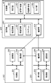
- FIG. 4 is a diagram showing a first example of the system configuration.
- the home control system includes an integrated controller 200, equipment 300, and server 400 (control device).
- the device 300 includes a control section 301 , a storage section 303 and a communication section 304 .
- the control unit 301 is implemented as a function such as a CPU by executing a predetermined program.
- the storage unit 303 is configured with a flash memory or the like.
- the communication unit 304 is configured with a communication module compatible with any communication method such as IP.
- the integrated controller 200 includes a control section 201 , a display section 202 , a storage section 203 and a communication section 204 .
- the control unit 201 is implemented as a function such as a CPU by executing a predetermined program.
- the display unit 202 is a touch panel display using liquid crystal, organic EL, or the like.
- the storage unit 203 is configured with an HDD, SSD, flash memory, or the like.
- the communication unit 304 is configured with a communication module compatible with any communication method such as IP.
- the server 400 includes a control unit 401, a storage unit 403, and a communication unit 404.
- the storage unit 403 is configured with an HDD, SSD, flash memory, or the like.
- the storage unit 403 stores installation information 601 , arrangement information 602 and programs 603 .
- the control unit 401 includes an acquisition unit 501, a space generation unit 502, a device control unit 503, and an output unit 504 as functions realized by a CPU or the like executing a program 603 read from the storage unit 403 to a ROM, RAM, or the like. It has Details of these functions will be described later.
- the communication unit 404 is configured with a communication module compatible with any communication method such as IP.
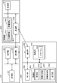
- FIG. 5 is a diagram showing a second example of the system configuration.
- the home control system includes an integrated controller 200 (control device), equipment 300 and server 400 .
- the integrated controller 200 includes a control section 201 , a display section 202 , a storage section 203 and a communication section 204 .
- a program 603 is stored in the storage unit 203 .
- the control unit 201 includes an acquisition unit 501, a space generation unit 502, a device control unit 503, and an output unit 504 as functions realized by the CPU or the like executing a program 603 read from the storage unit 203 into a ROM, RAM, or the like. It has
- the server 400 includes a control unit 401, a storage unit 403, and a communication unit 404.
- the storage unit 403 stores installation information 601 and layout information 602 .
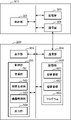
- FIG. 6 is a diagram showing a third example of the system configuration.
- the home control system includes an integrated controller 200 (control device) and equipment 300 .
- the integrated controller 200 includes a control section 201 , a display section 202 , a storage section 203 and a communication section 204 .
- Installation information 601 , arrangement information 602 , and programs 603 are stored in the storage unit 203 .
- the control unit 201 includes an acquisition unit 501, a space generation unit 502, a device control unit 503, and an output unit 504 as functions realized by the CPU or the like executing a program 603 read from the storage unit 203 into a ROM, RAM, or the like. It has
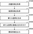
- FIG. 7 is a flowchart showing the flow of processing executed by the control unit 401 of the server 400.
- the control unit 401 generates relational information described later by executing the following processing when the system is introduced or when the device 300 is changed such as addition, removal, or replacement.
- step S ⁇ b>100 the acquisition unit 501 acquires the installation information 601 by reading the installation information 601 from the storage unit 403 .
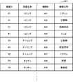
- FIG. 8 is a diagram showing a simplified example of the installation information 601.
- FIG. 8 If there are multiple smart homes 100 to be managed, installation information 601 is created for each smart home 100 .
- the installation information 601 is created by an operator of a management company or the like when the system is introduced into the smart home 100 . However, it may be created not by the operator but by the resident of the smart home 100, or may be created after the fact rather than when the system is introduced.
- the installation information 601 includes identification information (room ID and room name) for each of the plurality of rooms in the smart home 100 and identification information (device ID and device name) for each device 300 installed in each room. contains a correspondence with In this example, an air conditioner (device ID: A01), main lighting (device ID: A02), indirect lighting (device ID: A03), and a television (device ID: A04) are installed in the living room (room ID: R1). It is Main lighting (device ID: A05), indirect lighting (device ID: A06), and an air conditioner (device ID: A07) are installed in the dining room (room ID: R2).
- Lighting (equipment ID: A08) and a ventilation fan (equipment ID: A09) are installed in the kitchen (room ID: R3).
- the object to be managed is not limited to a room (a space surrounded by walls), but may be a space not surrounded by walls (entrance, stairs, corridor, etc.).
- the integrated controller 200 is placed on the stairs, the resident of the smart home 100 can use the integrated controller 200 to operate multiple devices 300 installed on each floor when going up or down the stairs. can be done.
- step S200 the acquisition unit 501 acquires the arrangement information 602 by reading the arrangement information 602 from the storage unit 403.
- FIG. 7 the acquisition unit 501 acquires the arrangement information 602 by reading the arrangement information 602 from the storage unit 403.
- FIG. 9 is a diagram showing a simplified example of the arrangement information 602.
- the arrangement information 602 is created by an operator of a management company or the like when the system is introduced into the smart home 100 . However, it may be created not by the operator but by the resident of the smart home 100, or may be created after the fact rather than when the system is introduced.
- the arrangement information 602 indicates identification information (controller ID) of the integrated controller 200, identification information (placement room ID) of the room in which the integrated controller 200 is arranged, and whether or not the integrated controller 200 corresponds to the entrance/exit. It includes the correspondence relationship between the doorway correspondence information and the identification information (combination object room ID) of two or more rooms to be combined when the integrated controller 200 is doorway correspondence.
- controller ID: C1 placement room ID: R1
- entrance correspondence: 0 combination target room ID: None
- controller ID: C2 arrangement room ID: R2
- entrance correspondence: 1 combination target room IDs: R1, R2, R3 are set.
- Entrance correspondence: 0 indicates that it is not entrance correspondence
- entrance correspondence: 1 indicates that it is entrance correspondence.
- step S300 space generation unit 502 selects, based on arrangement information 602 acquired by acquisition unit 501, combination target rooms among a plurality of spaces (first spaces) possessed by smart home 100.
- a new space (second space) is generated by combining two or more spaces included in the ID.
- FIG. 10 is a flowchart showing a specific example of processing in step S300.
- the space generation unit 502 determines whether or not each integrated controller 200 corresponds to an entrance based on the arrangement information 602 .
- the space generation unit 502 determines that the integrated controller 200B for which 1 is set for entrance/exit in the layout information 602 is for entrance/exit, and determines that the integrated controller 200A for which 0 is for entrance/exit is not for entrance/exit. .
- step S302 the space generation unit 502 acquires the combination target room ID from the layout information 602.
- step S303 the space generation unit 502 generates a new space by combining multiple rooms included in the combination target room IDs acquired in step S302.
- the doorway correspondence is 1, and the combination target room IDs are R1, R2, and R3. Therefore, space generation section 502 generates LDK 150 as a new space for integrated controller 200B.
- step S304 the space generation unit 502 acquires the layout room ID from the layout information 602, and converts the space indicated by the layout room ID into a new space.
- the entrance/exit correspondence is 0 and the room ID is R1. Therefore, space generation section 502 treats living room 151 as a new space for integrated controller 200A.
- step S300 a new space that is different from the space defined by the installation information 601 is generated.
- the installation information 601 first created by the operator of the management company or the resident, etc. the identification information of each room and the identification information of each device 300 are included for each room name described in the architectural drawing or the floor plan of each floor. is registered. Therefore, the new space created in step S300 is created as a space that is not represented by a room name such as an architectural drawing or a floor plan of each floor.
- the device control unit 503 gives identification information (ID and name) to the new space generated in step S300. Then, the device control unit 503 associates the identification information with the identification information of the two or more devices installed in the new space, thereby generating relationship information indicating the correspondence between them. For example, regarding the integrated controller 200B, when a new space LDK 150 is generated by combining the living room 151, dining room 152, and kitchen 153, the device control unit 503 assigns a new room ID and A new name (for example, “living dining kitchen”) is given. Further, the device control unit 503 generates relationship information by associating the new room ID with the device IDs (A01 to A09) of the two or more devices 300 installed in the LDK 150.
- step S500 the output unit 504 outputs the relationship information generated in step S400.
- the relationship information output by the output unit 504 is input to the communication unit 404.
- the communication unit 404 transmits the input related information to the integrated controller 200 via the communication network 500 .
- the communication unit 204 of the integrated controller 200 receives the relationship information and inputs the received relationship information to the control unit 201 .
- the control unit 201 creates display data based on the input relationship information.
- the control unit 201 inputs the created display data to the display unit 202 .
- the display unit 202 displays an operation screen based on the input display data.
- the mode of notification is not limited to display, and may be audio output or the like. Further, the mode of notification includes the output of display data or audio data to a device having a display unit or audio output unit.
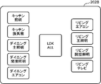
- FIG. 11 is a diagram showing a first example of an operation screen displayed on the display unit 202B of the integrated controller 200B corresponding to the entrance, according to the first embodiment of the present disclosure.
- An example of an operation screen when a new space called LDK 150 is generated by combining living room 151, dining room 152, and kitchen 153 will be described below. According to the example shown in FIG.
- the living room 151 air conditioner (device ID: A01), main lighting (device ID: A02), indirect lighting (device ID: A03), and television (device ID: A04), dining main lighting (device ID: A05), indirect lighting (device ID: A06), air conditioner (device ID: A07), kitchen lighting (device ID: A08) and ventilation fan (device ID : A09) is installed.
- the operation screen includes text representing the name “living dining kitchen”, individual control information for individually controlling a plurality of devices 300 installed in LDK 150, and collective control information for collectively controlling all the devices 300 that are present.
- the individual control information includes text representing the name of each device 300 (“living air conditioner”, “living main lighting”, “living indirect lighting”, “living TV”, “dining main lighting”, “dining indirect lighting”, “dining “air conditioner”, “kitchen lighting”, and “kitchen ventilation fan”), and an icon that is touched to turn on or off the power of each device 300.
- the integrated controller 200B turns on the power of the main lighting installed in the dining room 152 by remote control via the communication network.
- the integrated controller 200B turns off the power of the ventilation fan installed in the kitchen 153 by remote control via the communication network.
- Collective control information includes the text "All devices", a power-on icon, and a power-off icon.
- the integrated controller 200B remotely controls all the devices 300 installed in the LDK 150 (“living air conditioner,” “living room main lighting,” “living room “Indirect Lighting”, “Living TV”, “Dining Main Lighting”, “Dining Indirect Lighting”, “Dining Air Conditioner”, “Kitchen Lighting”, and “Kitchen Ventilation Fan”) are turned on.
- the integrated controller 200B powers off all the devices 300 installed in the LDK 150 by remote control via the communication network.
- the collective control information is not limited to an example in which all the devices 300 installed in a new space are subject to control.
- the configuration may be such that detailed settings for a desired device 300 can be performed.
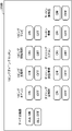
- FIG. 12 is a diagram showing a second example of the operation screen displayed on the display unit 202B of the integrated controller 200B that corresponds to the entrance, according to the first embodiment of the present disclosure.
- the operation screen includes collective control information including an icon imitating the floor plan of the LDK 150, and individual control information for individually controlling a plurality of devices 300 installed in the living room 151, dining room 152, and kitchen 153. .
- the integrated controller 200B remotely controls all devices installed in the LDK 150 via a communication network. 300 is turned on. Further, for example, when the icon displayed as "LDK” is touched for longer than the specified time, the integrated controller 200B controls all the devices 300 installed in the LDK 150 by remote control via the communication network. power off. As a modified example, although not shown in FIG. 12, instead of controlling whether the collective control operation is on or off according to the duration of the touch, the ON icon and the OFF icon for the collective control operation are explicitly displayed. may
- the icon of the device 300 in operation is lit, and the icon of the device 300 inactive is off.
- the integrated controller 200B powers off the device 300 corresponding to that icon by remote control via the communication network.
- the integrated controller 200B powers on the device 300 corresponding to that icon by remote control via the communication network.
- an individual control operation ON icon and an individual control operation OFF icon may be displayed for each device 300 as shown in FIG.
- FIG. 13 is a diagram showing an example of an operation screen displayed on the display unit 202A of the integrated controller 200A that is not entrance/exit compatible, according to the first embodiment of the present disclosure.
- the operation screen includes icons imitating the layout of a living room 151, a dining room 152, and a kitchen 153, and icons labeled with "L" are added with pop-up screens.
- the popup screen includes individual control information for individually controlling the plurality of devices 300 installed in the living room 151 and collective control information for collectively controlling the plurality of devices 300 installed in the living room 151. including.
- the icon of the device 300 in operation is lit, and the icon of the device 300 inactive is off.
- the integrated controller 200A powers off the device 300 corresponding to that icon by remote control via the communication network.
- the integrated controller 200A powers on the device 300 corresponding to that icon by remote control via the communication network.
- an individual control operation ON icon and an individual control operation OFF icon may be displayed for each device 300 as shown in FIG.
- integrated controller 200A controls all of the items installed in living room 151 by remote control via a communication network. Power on the device 300 . Further, for example, when the icon displayed as "ALL" is touched for longer than the specified time, the integrated controller 200A controls all devices installed in the living room 151 by remote control via the communication network. 300 is turned off. As a modified example, although not shown in FIG. 13, instead of controlling whether the collective control operation is on or off according to the touch duration, the ON icon and the OFF icon for the collective control operation are explicitly displayed. may
- operation icons for a plurality of devices 300 installed in one room (first space) are displayed. It is called "normal display” for distinction.
- the integrated controller 200B which is compatible with entrances and exits, does not always need to perform the summary display, and may switch between the summary display and the normal display according to a predetermined switching condition.
- FIG. 14 is a flowchart showing a first example of switching conditions.
- the integrated controller 200B switches between summary display and normal display depending on whether or not a person other than the operator of the integrated controller 200B is detected within the LDK 150 .
- step S ⁇ b>351 the device control unit 503 determines whether or not a person has been detected near the entrance/exit 162 .
- a person near the entrance/exit 162 is detected by a touch sensor (not shown) mounted on the integrated controller 200B, or by a camera or a human sensor (both not shown) whose detection target area is the area 190 near the entrance/exit 162. , can be detected.
- step S351 If a person is detected near the entrance/exit 162 (step S351: YES), then in step S352, the device control unit 503 detects the entrance/exit 162 in the second space (LDK 150) generated by the space generation unit 502. Determine whether or not a person has been detected in the room excluding the vicinity. A person in the room except near the entrance/exit 162 can be detected by the camera 180 shown in FIG.
- step S353 the device control unit 503 performs summary display.
- step S354 the device control unit 503 displays normal display. conduct.
- the user can control only the device 300 installed in the dining room 152 where the integrated controller 200B is arranged by the integrated controller 200B. User convenience can be improved.
- FIG. 15 is a flowchart showing a second example of switching conditions.
- the integrated controller 200B switches between summary display and normal display depending on whether the current time belongs to a predetermined designated time period.
- the designated time period is preset as a time period in which the frequency of entry and exit through the entrance/exit 162 is higher than a predetermined threshold.
- the setting information for the designated time period is stored in advance in a non-volatile memory that can be referred to by the device control section 503 .
- step S361 the device control unit 503 acquires time information indicating the current time.
- step S362 the device control section 503 determines whether or not the current time belongs to the designated time period.
- step S363 the device control unit 503 performs summary display.
- step S364 the device control unit 503 performs normal display.
- the user can control only the device 300 installed in the dining room 152 where the integrated controller 200B is arranged, thereby increasing user convenience. It is possible to improve the performance.
- the display unit 202A (notification unit) is provided in two or more units installed in the LDK 150 (second space).
- Collective control information for collectively controlling the devices 300 is displayed. Therefore, the user can collectively control two or more devices 300 installed in the LDK 150 by means of the integrated controller 200B arranged near the doorway 162, thereby improving convenience for the user. .
- the home control system when integrated controller 200 is integrated controller 200A that does not correspond to the entrance/exit, two or more display units 202B are installed in living room 151 (specific first space). collective control information for controlling the devices 300 collectively. Therefore, the user can control only the device 300 installed in the living room 151 where the integrated controller 200A is located by the integrated controller 200A located away from the entrances 161 and 162, which is convenient for the user. can be improved.
- FIG. 16 is a diagram showing a first example of an operation screen displayed on the display unit 202B of the integrated controller 200B corresponding to the entrance, according to the second embodiment of the present disclosure.
- An example of an operation screen when a new space called LDK 150 is generated by combining living room 151, dining room 152, and kitchen 153 will be described below. According to the example shown in FIG.
- the living room 151 air conditioner (device ID: A01), main lighting (device ID: A02), indirect lighting (device ID: A03), and television (device ID: A04), dining main lighting (device ID: A05), indirect lighting (device ID: A06), air conditioner (device ID: A07), kitchen lighting (device ID: A08) and ventilation fan (device ID : A09) is installed.
- the operation screen includes text representing the name "living dining kitchen” and individual control information for individually controlling a plurality of devices 300 installed in LDK 150.
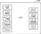
- the individual control information includes text representing the name of each device 300 (“living air conditioner”, “living main lighting”, “living indirect lighting”, “living TV”, “dining main lighting”, “dining indirect lighting”, “dining “air conditioner”, “kitchen lighting”, and “kitchen ventilation fan”), and an icon that is touched to turn on or off the power of each device 300.
- the integrated controller 200B turns on the power of the main lighting installed in the dining room 152 by remote control via the communication network.
- the integrated controller 200B turns off the power of the ventilation fan installed in the kitchen 153 by remote control via the communication network.
- FIG. 17 is a diagram showing a second example of the operation screen displayed on the display unit 202B of the integrated controller 200B that corresponds to the entrance, according to the second embodiment of the present disclosure.
- the operation screen includes text representing the name “LDK” and individual control information for individually controlling a plurality of devices 300 installed in living room 151, dining room 152, and kitchen 153, respectively.
- the icon of the device 300 in operation is lit, and the icon of the device 300 inactive is off.
- the integrated controller 200B powers off the device 300 corresponding to that icon by remote control via the communication network.
- the integrated controller 200B powers on the device 300 corresponding to that icon by remote control via the communication network.
- an individual control operation ON icon and an individual control operation OFF icon may be displayed for each device 300 as shown in FIG.
- the display unit 202A (notification unit) is provided in two or more units installed in the LDK 150 (second space). Individual control information for individually controlling the device 300 is displayed. Therefore, the user can collectively display and individually control two or more devices 300 installed in the LDK 150 by means of the integrated controller 200B arranged near the doorway 162, thereby improving user convenience. becomes possible.
- the home control system when integrated controller 200 is integrated controller 200A that does not correspond to the entrance/exit, two or more display units 202B are installed in living room 151 (specific first space). individual control information for individually controlling the devices 300 of the above. Therefore, the user can control only the device 300 installed in the living room 151 where the integrated controller 200A is located by the integrated controller 200A located away from the entrances 161 and 162, which is convenient for the user. can be improved.
- the present disclosure is particularly useful when applied to home control systems equipped with smart homes incorporating IoT technology.
Landscapes
- Engineering & Computer Science (AREA)
- Automation & Control Theory (AREA)
- Computer Networks & Wireless Communication (AREA)
- Signal Processing (AREA)
- Human Computer Interaction (AREA)
- Selective Calling Equipment (AREA)
Abstract
Description
IoT技術が導入されたスマートホーム等においては、住宅の複数の部屋に設置された複数の機器を統合して制御するための制御装置(ホームコントローラ)が使用されることがある。例えば上記特許文献1には、住宅の複数の部屋に設置された複数の機器の電源オン又は電源オフを操作するためのホームコントローラが開示されている。当該ホームコントローラでは、住宅の部屋単位で機器が管理されている。
以下、本開示の実施の形態について、図面を用いて詳細に説明する。異なる図面において同一の符号を付した要素は、同一又は相応する要素を示すものとする。また、以下の実施の形態で示される構成要素、構成要素の配置位置、接続形態、及び動作の順序等は、一例であり、本開示を限定する趣旨ではない。本開示は、特許請求の範囲だけによって限定される。よって、以下の実施の形態における構成要素のうち、本開示の最上位概念を示す独立請求項に記載されていない構成要素については、本開示の課題を達成するのに必ずしも必要ではないが、より好ましい形態を構成するものとして説明される。
図11は、本開示の第1の実施の形態に関して、出入口対応である統合コントローラ200Bの表示部202Bに表示される操作画面の第1の例を示す図である。以下では、リビング151、ダイニング152、及びキッチン153を組み合わせることによってLDK150という新たな空間が生成された場合の操作画面の例について説明する。図8に示した例によると、LDK150という新たな空間には、リビング151のエアコン(機器ID:A01)、主照明(機器ID:A02)、間接照明(機器ID:A03)、及びテレビ(機器ID:A04)と、ダイニングの主照明(機器ID:A05)、間接照明(機器ID:A06)、及びエアコン(機器ID:A07)と、キッチンの照明(機器ID:A08)及び換気扇(機器ID:A09)とが設置されている。
図16は、本開示の第2の実施の形態に関して、出入口対応である統合コントローラ200Bの表示部202Bに表示される操作画面の第1の例を示す図である。以下では、リビング151、ダイニング152、及びキッチン153を組み合わせることによってLDK150という新たな空間が生成された場合の操作画面の例について説明する。図8に示した例によると、LDK150という新たな空間には、リビング151のエアコン(機器ID:A01)、主照明(機器ID:A02)、間接照明(機器ID:A03)、及びテレビ(機器ID:A04)と、ダイニングの主照明(機器ID:A05)、間接照明(機器ID:A06)、及びエアコン(機器ID:A07)と、キッチンの照明(機器ID:A08)及び換気扇(機器ID:A09)とが設置されている。
Claims (11)
- 複数の第1空間を有する建物内に設置された複数の機器を制御する制御装置であって、
設置情報及び配置情報を取得する取得部と、
空間生成部と、
機器制御部と、
報知部と、
を備え、
前記設置情報は、前記複数の第1空間の各第1空間の識別情報と、前記複数の機器のうち前記各第1空間に設置されている各機器の識別情報との対応関係を含み、
前記配置情報は、前記制御装置の識別情報と、前記複数の第1空間のうち前記制御装置が配置されている特定の第1空間の識別情報と、前記制御装置が出入口対応であるか否かを示す出入口対応情報と、前記複数の第1空間のうち前記制御装置が出入口対応である場合に組み合わされる二以上の第1空間の識別情報との対応関係を含み、
前記制御装置が出入口対応である場合、
前記空間生成部は、前記取得部が取得した前記配置情報に基づいて、前記二以上の第1空間を組み合わせることによって第2空間を生成し、
前記機器制御部は、前記第2空間の識別情報と、前記複数の機器のうち前記第2空間に設置されている二以上の機器の識別情報との対応関係を示す関係情報を生成し、
前記報知部は、前記機器制御部が生成した前記関係情報に基づいて、前記第2空間に設置されている前記二以上の機器を一括して制御するための一括制御情報及び前記第2空間に設置されている前記二以上の機器を個別に制御するための個別制御情報の少なくとも一方を報知する、制御装置。 - 前記報知部は前記一括制御情報を報知し、
前記制御装置が出入口対応でない場合、
前記機器制御部は、前記特定の第1空間の識別情報と、前記複数の機器のうち前記特定の第1空間に設置されている二以上の機器の識別情報との対応関係を示す関係情報を生成し、
前記報知部は、前記機器制御部が生成した前記関係情報に基づいて、前記特定の第1空間に設置されている前記二以上の機器を一括して制御するための一括制御情報を報知する、請求項1に記載の制御装置。 - 前記報知部は前記一括制御情報を報知し、
前記報知部は表示部を有し、
前記表示部は、前記第2空間の識別情報と、前記第2空間に設置されている前記二以上の機器の各機器の識別情報と、当該二以上の機器を一括して制御するための前記一括制御情報としてのアイコンとを表示する、請求項1又は2に記載の制御装置。 - 前記報知部は前記一括制御情報及び前記個別制御情報を報知する、請求項1~3のいずれか一つに記載の制御装置。
- 前記報知部は前記個別制御情報を報知し、
前記制御装置が出入口対応でない場合、
前記機器制御部は、前記特定の第1空間の識別情報と、前記複数の機器のうち前記特定の第1空間に設置されている二以上の機器の識別情報との対応関係を示す関係情報を生成し、
前記報知部は、前記機器制御部が生成した前記関係情報に基づいて、前記特定の第1空間に設置されている前記二以上の機器を個別に制御するための個別制御情報を報知する、請求項1に記載の制御装置。 - 前記報知部は前記個別制御情報を報知し、
前記報知部は表示部を有し、
前記表示部は、前記第2空間の識別情報と、前記第2空間に設置されている前記二以上の機器の各機器の識別情報と、当該二以上の機器を個別に制御するための前記個別制御情報としてのアイコンとを表示する、請求項1又は5に記載の制御装置。 - 前記第2空間内において前記制御装置の操作者以外の人物を検出する検出部をさらに備え、
前記検出部が前記人物を検出している場合、
前記機器制御部は、前記特定の第1空間の識別情報と、前記複数の機器のうち前記特定の第1空間に設置されている二以上の機器の識別情報との対応関係を示す関係情報を生成し、
前記報知部は、前記機器制御部が生成した前記関係情報に基づいて、前記特定の第1空間に設置されている前記二以上の機器を制御するための制御情報を報知する、請求項1~6のいずれか一つに記載の制御装置。 - 現在時刻が、予め定められた指定時間帯に属さない場合、
前記機器制御部は、前記特定の第1空間の識別情報と、前記複数の機器のうち前記特定の第1空間に設置されている二以上の機器の識別情報との対応関係を示す関係情報を生成し、
前記報知部は、前記機器制御部が生成した前記関係情報に基づいて、前記特定の第1空間に設置されている前記二以上の機器を制御するための制御情報を報知する、請求項1~7のいずれか一つに記載の制御装置。 - 前記第2空間は、リビング、ダイニング、及びキッチンの少なくとも二つを含む、請求項1~8のいずれか一つに記載の制御装置。
- 複数の第1空間を有する建物内に設置された複数の機器を制御する制御装置に搭載されるコンピュータを、
設置情報及び配置情報を取得する取得手段と、
空間生成手段と、
機器制御手段と、
出力手段と、
として機能させるためのプログラムであって、
前記設置情報は、前記複数の第1空間の各第1空間の識別情報と、前記複数の機器のうち前記各第1空間に設置されている各機器の識別情報との対応関係を含み、
前記配置情報は、前記制御装置の識別情報と、前記複数の第1空間のうち前記制御装置が配置されている特定の第1空間の識別情報と、前記制御装置が出入口対応であるか否かを示す出入口対応情報と、前記複数の第1空間のうち前記制御装置が出入口対応である場合に組み合わされる二以上の第1空間の識別情報との対応関係を含み、
前記制御装置が出入口対応である場合、
前記空間生成手段は、前記取得手段が取得した前記配置情報に基づいて、前記二以上の第1空間を組み合わせることによって第2空間を生成し、
前記機器制御手段は、前記第2空間の識別情報と、前記複数の機器のうち前記第2空間に設置されている二以上の機器の識別情報との対応関係を示す関係情報を生成し、
前記出力手段は、前記機器制御部が生成した前記関係情報に基づいて前記第2空間に設置されている前記二以上の機器を一括して制御するための一括制御情報及び前記第2空間に設置されている前記二以上の機器を個別に制御するための個別制御情報の少なくとも一方を報知する報知部に向けて、前記関係情報を出力する、プログラム。 - 複数の第1空間を有する建物内に設置された複数の機器を制御する制御方法であって、
前記設置情報は、前記複数の第1空間の各第1空間の識別情報と、前記複数の機器のうち前記各第1空間に設置されている各機器の識別情報との対応関係を含み、
前記配置情報は、前記制御装置の識別情報と、前記複数の第1空間のうち前記制御装置が配置されている特定の第1空間の識別情報と、前記制御装置が出入口対応であるか否かを示す出入口対応情報と、前記複数の第1空間のうち前記制御装置が出入口対応である場合に組み合わされる二以上の第1空間の識別情報との対応関係を含み、
前記制御装置が出入口対応である場合、
コンピュータが、
取得した前記配置情報に基づいて、前記二以上の第1空間を組み合わせることによって第2空間を生成し、
前記第2空間の識別情報と、前記複数の機器のうち前記第2空間に設置されている二以上の機器の識別情報との対応関係を示す関係情報を生成し、
前記関係情報に基づいて前記第2空間に設置されている前記二以上の機器を一括して制御するための一括制御情報及び前記第2空間に設置されている前記二以上の機器を個別に制御するための個別制御情報の少なくとも一方を報知する報知部に向けて、前記関係情報を出力する、制御方法。
Priority Applications (3)
| Application Number | Priority Date | Filing Date | Title |
|---|---|---|---|
| CN202280022057.4A CN117044224A (zh) | 2021-03-19 | 2022-01-24 | 控制装置、程序以及控制方法 |
| JP2023506812A JP7741168B2 (ja) | 2021-03-19 | 2022-01-24 | 制御装置、プログラム、及び制御方法 |
| US18/368,252 US12047192B2 (en) | 2021-03-19 | 2023-09-14 | Control device, computer-readable recording medium recording a program, and control method |
Applications Claiming Priority (4)
| Application Number | Priority Date | Filing Date | Title |
|---|---|---|---|
| JP2021045731 | 2021-03-19 | ||
| JP2021-045731 | 2021-03-19 | ||
| JP2021-045732 | 2021-03-19 | ||
| JP2021045732 | 2021-03-19 |
Related Child Applications (1)
| Application Number | Title | Priority Date | Filing Date |
|---|---|---|---|
| US18/368,252 Continuation US12047192B2 (en) | 2021-03-19 | 2023-09-14 | Control device, computer-readable recording medium recording a program, and control method |
Publications (1)
| Publication Number | Publication Date |
|---|---|
| WO2022196102A1 true WO2022196102A1 (ja) | 2022-09-22 |
Family
ID=83320242
Family Applications (1)
| Application Number | Title | Priority Date | Filing Date |
|---|---|---|---|
| PCT/JP2022/002430 Ceased WO2022196102A1 (ja) | 2021-03-19 | 2022-01-24 | 制御装置、プログラム、及び制御方法 |
Country Status (3)
| Country | Link |
|---|---|
| US (1) | US12047192B2 (ja) |
| JP (1) | JP7741168B2 (ja) |
| WO (1) | WO2022196102A1 (ja) |
Citations (5)
| Publication number | Priority date | Publication date | Assignee | Title |
|---|---|---|---|---|
| JP2003316983A (ja) * | 2002-04-26 | 2003-11-07 | Hitachi Ltd | コンピュータを利用した受注システム及びその受注システムを備えた店舗 |
| JP5663711B1 (ja) * | 2014-01-29 | 2015-02-04 | パナソニック インテレクチュアル プロパティ コーポレーション オブアメリカPanasonic Intellectual Property Corporation of America | 情報端末の制御方法及びプログラム |
| JP2016129436A (ja) * | 2016-04-15 | 2016-07-14 | ソニー株式会社 | 無線操作装置、無線操作システム及び無線操作方法 |
| JP2016171407A (ja) * | 2015-03-12 | 2016-09-23 | 富士通株式会社 | 情報処理装置、機器特定方法、及び、機器特定プログラム |
| JP2017038372A (ja) * | 2013-03-29 | 2017-02-16 | パナソニック インテレクチュアル プロパティ コーポレーション オブ アメリカPanasonic Intellectual Property Corporation of America | 情報端末のプログラム、制御方法、情報提供方法及び情報端末 |
Family Cites Families (4)
| Publication number | Priority date | Publication date | Assignee | Title |
|---|---|---|---|---|
| CN104255040B8 (zh) | 2013-02-20 | 2019-03-08 | 松下电器(美国)知识产权公司 | 信息终端的控制方法和程序 |
| GB201720331D0 (en) * | 2017-12-06 | 2018-01-17 | Spaceti Uk Ltd | Systems integrator, building management, control and monitoring system |
| US11147459B2 (en) * | 2018-01-05 | 2021-10-19 | CareBand Inc. | Wearable electronic device and system for tracking location and identifying changes in salient indicators of patient health |
| US12215977B2 (en) * | 2020-04-20 | 2025-02-04 | T-Mobile Usa, Inc. | Localization using internet of things devices |
-
2022
- 2022-01-24 WO PCT/JP2022/002430 patent/WO2022196102A1/ja not_active Ceased
- 2022-01-24 JP JP2023506812A patent/JP7741168B2/ja active Active
-
2023
- 2023-09-14 US US18/368,252 patent/US12047192B2/en active Active
Patent Citations (5)
| Publication number | Priority date | Publication date | Assignee | Title |
|---|---|---|---|---|
| JP2003316983A (ja) * | 2002-04-26 | 2003-11-07 | Hitachi Ltd | コンピュータを利用した受注システム及びその受注システムを備えた店舗 |
| JP2017038372A (ja) * | 2013-03-29 | 2017-02-16 | パナソニック インテレクチュアル プロパティ コーポレーション オブ アメリカPanasonic Intellectual Property Corporation of America | 情報端末のプログラム、制御方法、情報提供方法及び情報端末 |
| JP5663711B1 (ja) * | 2014-01-29 | 2015-02-04 | パナソニック インテレクチュアル プロパティ コーポレーション オブアメリカPanasonic Intellectual Property Corporation of America | 情報端末の制御方法及びプログラム |
| JP2016171407A (ja) * | 2015-03-12 | 2016-09-23 | 富士通株式会社 | 情報処理装置、機器特定方法、及び、機器特定プログラム |
| JP2016129436A (ja) * | 2016-04-15 | 2016-07-14 | ソニー株式会社 | 無線操作装置、無線操作システム及び無線操作方法 |
Also Published As
| Publication number | Publication date |
|---|---|
| US20240007320A1 (en) | 2024-01-04 |
| US12047192B2 (en) | 2024-07-23 |
| JPWO2022196102A1 (ja) | 2022-09-22 |
| JP7741168B2 (ja) | 2025-09-17 |
Similar Documents
| Publication | Publication Date | Title |
|---|---|---|
| US10237141B2 (en) | Method for controlling information apparatus and computer-readable recording medium | |
| US20150261427A1 (en) | Method for controlling information apparatus and computer-readable recording medium | |
| WO2018146742A1 (ja) | 管理装置及び空調システム | |
| US20140062340A1 (en) | Electrical Switch Device with Automatic Control | |
| WO2014103307A1 (ja) | 制御方法 | |
| KR20170002244A (ko) | 복수의 구역들 중 일 구역의 기기를 제어하는 방법 및 이를 위한 장치 | |
| WO2014185174A1 (ja) | エネルギーマネジメントコントローラ、エネルギーマネジメントシステム、エネルギーマネジメント方法、及び、プログラム | |
| JP6782464B2 (ja) | 情報作成方法、情報作成システム及びプログラム | |
| JP7557747B2 (ja) | 室内環境制御システム、及び、室内環境制御方法 | |
| WO2017203799A1 (ja) | エネルギー管理装置、管理システム、消費電力監視方法及びプログラム | |
| CN104583987B (zh) | 机器管理装置 | |
| WO2022196102A1 (ja) | 制御装置、プログラム、及び制御方法 | |
| CN117044224A (zh) | 控制装置、程序以及控制方法 | |
| JP7817198B2 (ja) | 制御装置、プログラム、及び制御方法 | |
| JP5432536B2 (ja) | 機器ネットワークシステム | |
| JP7775289B2 (ja) | 空間生成方法、情報処理装置、及びプログラム | |
| JP2019024239A (ja) | 遠隔制御システムおよびサーバ | |
| JP7486158B2 (ja) | 情報処理システム、及び、情報処理方法 | |
| JP2019203615A (ja) | 空調操作装置 | |
| JP2013258673A (ja) | 表示装置、テレビジョン受信機及びプログラム | |
| JP6678696B2 (ja) | 無線階層電源管理システム、その遠隔制御装置、及びその被制御装置、並びに遠隔制御方法 | |
| WO2021024990A1 (ja) | 制御システム、及び、制御方法 | |
| WO2023008257A1 (ja) | 情報出力方法、情報出力装置、及びプログラム | |
| JP2026071315A (ja) | 制御装置、プログラム、及び制御方法 | |
| JP7733606B2 (ja) | 操作システム、制御方法及びプログラム |
Legal Events
| Date | Code | Title | Description |
|---|---|---|---|
| 121 | Ep: the epo has been informed by wipo that ep was designated in this application |
Ref document number: 22770864 Country of ref document: EP Kind code of ref document: A1 |
|
| WWE | Wipo information: entry into national phase |
Ref document number: 2023506812 Country of ref document: JP |
|
| WWE | Wipo information: entry into national phase |
Ref document number: 202280022057.4 Country of ref document: CN |
|
| NENP | Non-entry into the national phase |
Ref country code: DE |
|
| 122 | Ep: pct application non-entry in european phase |
Ref document number: 22770864 Country of ref document: EP Kind code of ref document: A1 |