WO2022195899A1 - Pressure-sensitive adhesive tape - Google Patents
Pressure-sensitive adhesive tape Download PDFInfo
- Publication number
- WO2022195899A1 WO2022195899A1 PCT/JP2021/016843 JP2021016843W WO2022195899A1 WO 2022195899 A1 WO2022195899 A1 WO 2022195899A1 JP 2021016843 W JP2021016843 W JP 2021016843W WO 2022195899 A1 WO2022195899 A1 WO 2022195899A1
- Authority
- WO
- WIPO (PCT)
- Prior art keywords
- adhesive tape
- layer
- laminate layer
- base fabric
- warp
- Prior art date
Links
- 239000004820 Pressure-sensitive adhesive Substances 0.000 title claims abstract description 37
- 239000004744 fabric Substances 0.000 claims abstract description 68
- 239000003795 chemical substances by application Substances 0.000 claims abstract description 12
- 239000000758 substrate Substances 0.000 claims abstract description 8
- 239000010410 layer Substances 0.000 claims description 129
- 239000002390 adhesive tape Substances 0.000 claims description 42
- 239000000463 material Substances 0.000 claims description 18
- -1 polyethylene Polymers 0.000 claims description 17
- 238000003851 corona treatment Methods 0.000 claims description 11
- 229920005992 thermoplastic resin Polymers 0.000 claims description 8
- 239000004698 Polyethylene Substances 0.000 claims description 7
- 229920000573 polyethylene Polymers 0.000 claims description 7
- 229920000728 polyester Polymers 0.000 claims description 4
- 239000000853 adhesive Substances 0.000 abstract description 35
- 230000001070 adhesive effect Effects 0.000 description 33
- 239000012790 adhesive layer Substances 0.000 description 25
- 229920005989 resin Polymers 0.000 description 20
- 239000011347 resin Substances 0.000 description 20
- 238000011282 treatment Methods 0.000 description 16
- 229920001971 elastomer Polymers 0.000 description 11
- NIXOWILDQLNWCW-UHFFFAOYSA-M Acrylate Chemical compound [O-]C(=O)C=C NIXOWILDQLNWCW-UHFFFAOYSA-M 0.000 description 9
- 239000003522 acrylic cement Substances 0.000 description 9
- 239000005060 rubber Substances 0.000 description 9
- 238000000034 method Methods 0.000 description 7
- 230000000052 comparative effect Effects 0.000 description 6
- 239000000835 fiber Substances 0.000 description 6
- 229920001577 copolymer Polymers 0.000 description 5
- 239000000126 substance Substances 0.000 description 5
- NLHHRLWOUZZQLW-UHFFFAOYSA-N Acrylonitrile Chemical group C=CC#N NLHHRLWOUZZQLW-UHFFFAOYSA-N 0.000 description 4
- XTXRWKRVRITETP-UHFFFAOYSA-N Vinyl acetate Chemical compound CC(=O)OC=C XTXRWKRVRITETP-UHFFFAOYSA-N 0.000 description 4
- NIXOWILDQLNWCW-UHFFFAOYSA-N acrylic acid group Chemical group C(C=C)(=O)O NIXOWILDQLNWCW-UHFFFAOYSA-N 0.000 description 4
- 229920005601 base polymer Polymers 0.000 description 4
- 239000011248 coating agent Substances 0.000 description 4
- 238000000576 coating method Methods 0.000 description 4
- 238000001816 cooling Methods 0.000 description 4
- 238000005520 cutting process Methods 0.000 description 4
- 238000009940 knitting Methods 0.000 description 4
- 239000003208 petroleum Substances 0.000 description 4
- 238000004381 surface treatment Methods 0.000 description 4
- SMZOUWXMTYCWNB-UHFFFAOYSA-N 2-(2-methoxy-5-methylphenyl)ethanamine Chemical compound COC1=CC=C(C)C=C1CCN SMZOUWXMTYCWNB-UHFFFAOYSA-N 0.000 description 3
- 239000005062 Polybutadiene Substances 0.000 description 3
- 239000004743 Polypropylene Substances 0.000 description 3
- 239000000654 additive Substances 0.000 description 3
- 238000003475 lamination Methods 0.000 description 3
- 238000005259 measurement Methods 0.000 description 3
- 239000000178 monomer Substances 0.000 description 3
- 229920002857 polybutadiene Polymers 0.000 description 3
- 229920013716 polyethylene resin Polymers 0.000 description 3
- 229920001155 polypropylene Polymers 0.000 description 3
- VZCYOOQTPOCHFL-UHFFFAOYSA-N trans-butenedioic acid Natural products OC(=O)C=CC(O)=O VZCYOOQTPOCHFL-UHFFFAOYSA-N 0.000 description 3
- VZCYOOQTPOCHFL-OWOJBTEDSA-N Fumaric acid Chemical compound OC(=O)\C=C\C(O)=O VZCYOOQTPOCHFL-OWOJBTEDSA-N 0.000 description 2
- 244000043261 Hevea brasiliensis Species 0.000 description 2
- 229920002873 Polyethylenimine Polymers 0.000 description 2
- OFOBLEOULBTSOW-UHFFFAOYSA-N Propanedioic acid Natural products OC(=O)CC(O)=O OFOBLEOULBTSOW-UHFFFAOYSA-N 0.000 description 2
- 229920000297 Rayon Polymers 0.000 description 2
- PPBRXRYQALVLMV-UHFFFAOYSA-N Styrene Chemical group C=CC1=CC=CC=C1 PPBRXRYQALVLMV-UHFFFAOYSA-N 0.000 description 2
- 239000007795 chemical reaction product Substances 0.000 description 2
- 239000000806 elastomer Substances 0.000 description 2
- 238000001125 extrusion Methods 0.000 description 2
- 230000001771 impaired effect Effects 0.000 description 2
- 239000012948 isocyanate Substances 0.000 description 2
- 150000002513 isocyanates Chemical class 0.000 description 2
- 239000011976 maleic acid Substances 0.000 description 2
- VZCYOOQTPOCHFL-UPHRSURJSA-N maleic acid group Chemical group C(\C=C/C(=O)O)(=O)O VZCYOOQTPOCHFL-UPHRSURJSA-N 0.000 description 2
- 238000004519 manufacturing process Methods 0.000 description 2
- 239000000203 mixture Substances 0.000 description 2
- 229920003052 natural elastomer Polymers 0.000 description 2
- 229920001194 natural rubber Polymers 0.000 description 2
- 229920001568 phenolic resin Polymers 0.000 description 2
- 239000005011 phenolic resin Substances 0.000 description 2
- 238000004544 sputter deposition Methods 0.000 description 2
- 229920003048 styrene butadiene rubber Polymers 0.000 description 2
- 229920002994 synthetic fiber Polymers 0.000 description 2
- 239000012209 synthetic fiber Substances 0.000 description 2
- 238000012360 testing method Methods 0.000 description 2
- 229920001169 thermoplastic Polymers 0.000 description 2
- 239000004416 thermosoftening plastic Substances 0.000 description 2
- KPAPHODVWOVUJL-UHFFFAOYSA-N 1-benzofuran;1h-indene Chemical compound C1=CC=C2CC=CC2=C1.C1=CC=C2OC=CC2=C1 KPAPHODVWOVUJL-UHFFFAOYSA-N 0.000 description 1
- QJJDJWUCRAPCOL-UHFFFAOYSA-N 1-ethenoxyoctadecane Chemical compound CCCCCCCCCCCCCCCCCCOC=C QJJDJWUCRAPCOL-UHFFFAOYSA-N 0.000 description 1
- JAHNSTQSQJOJLO-UHFFFAOYSA-N 2-(3-fluorophenyl)-1h-imidazole Chemical compound FC1=CC=CC(C=2NC=CN=2)=C1 JAHNSTQSQJOJLO-UHFFFAOYSA-N 0.000 description 1
- 125000000954 2-hydroxyethyl group Chemical group [H]C([*])([H])C([H])([H])O[H] 0.000 description 1
- KXGFMDJXCMQABM-UHFFFAOYSA-N 2-methoxy-6-methylphenol Chemical compound [CH]OC1=CC=CC([CH])=C1O KXGFMDJXCMQABM-UHFFFAOYSA-N 0.000 description 1
- JTHZUSWLNCPZLX-UHFFFAOYSA-N 6-fluoro-3-methyl-2h-indazole Chemical compound FC1=CC=C2C(C)=NNC2=C1 JTHZUSWLNCPZLX-UHFFFAOYSA-N 0.000 description 1
- RSWGJHLUYNHPMX-UHFFFAOYSA-N Abietic-Saeure Natural products C12CCC(C(C)C)=CC2=CCC2C1(C)CCCC2(C)C(O)=O RSWGJHLUYNHPMX-UHFFFAOYSA-N 0.000 description 1
- QTBSBXVTEAMEQO-UHFFFAOYSA-M Acetate Chemical compound CC([O-])=O QTBSBXVTEAMEQO-UHFFFAOYSA-M 0.000 description 1
- HRPVXLWXLXDGHG-UHFFFAOYSA-N Acrylamide Chemical compound NC(=O)C=C HRPVXLWXLXDGHG-UHFFFAOYSA-N 0.000 description 1
- VGGSQFUCUMXWEO-UHFFFAOYSA-N Ethene Chemical compound C=C VGGSQFUCUMXWEO-UHFFFAOYSA-N 0.000 description 1
- 239000005977 Ethylene Substances 0.000 description 1
- 239000004606 Fillers/Extenders Substances 0.000 description 1
- CERQOIWHTDAKMF-UHFFFAOYSA-N Methacrylic acid Chemical compound CC(=C)C(O)=O CERQOIWHTDAKMF-UHFFFAOYSA-N 0.000 description 1
- 239000004677 Nylon Substances 0.000 description 1
- CTQNGGLPUBDAKN-UHFFFAOYSA-N O-Xylene Chemical compound CC1=CC=CC=C1C CTQNGGLPUBDAKN-UHFFFAOYSA-N 0.000 description 1
- KHPCPRHQVVSZAH-HUOMCSJISA-N Rosin Natural products O(C/C=C/c1ccccc1)[C@H]1[C@H](O)[C@@H](O)[C@@H](O)[C@@H](CO)O1 KHPCPRHQVVSZAH-HUOMCSJISA-N 0.000 description 1
- 229910000831 Steel Inorganic materials 0.000 description 1
- RTAQQCXQSZGOHL-UHFFFAOYSA-N Titanium Chemical compound [Ti] RTAQQCXQSZGOHL-UHFFFAOYSA-N 0.000 description 1
- 238000007259 addition reaction Methods 0.000 description 1
- 125000002723 alicyclic group Chemical group 0.000 description 1
- 125000001931 aliphatic group Chemical group 0.000 description 1
- 125000000217 alkyl group Chemical group 0.000 description 1
- 238000004873 anchoring Methods 0.000 description 1
- 150000008064 anhydrides Chemical class 0.000 description 1
- 239000003963 antioxidant agent Substances 0.000 description 1
- 125000003118 aryl group Chemical group 0.000 description 1
- CQEYYJKEWSMYFG-UHFFFAOYSA-N butyl acrylate Chemical compound CCCCOC(=O)C=C CQEYYJKEWSMYFG-UHFFFAOYSA-N 0.000 description 1
- 229920005549 butyl rubber Polymers 0.000 description 1
- 238000010538 cationic polymerization reaction Methods 0.000 description 1
- 238000006482 condensation reaction Methods 0.000 description 1
- 238000010276 construction Methods 0.000 description 1
- 239000003431 cross linking reagent Substances 0.000 description 1
- LDHQCZJRKDOVOX-NSCUHMNNSA-N crotonic acid Chemical compound C\C=C\C(O)=O LDHQCZJRKDOVOX-NSCUHMNNSA-N 0.000 description 1
- 230000006866 deterioration Effects 0.000 description 1
- 230000000694 effects Effects 0.000 description 1
- 238000005530 etching Methods 0.000 description 1
- 125000001495 ethyl group Chemical group [H]C([H])([H])C([H])([H])* 0.000 description 1
- 239000005038 ethylene vinyl acetate Substances 0.000 description 1
- 238000011156 evaluation Methods 0.000 description 1
- 239000000945 filler Substances 0.000 description 1
- 239000003063 flame retardant Substances 0.000 description 1
- 239000001530 fumaric acid Substances 0.000 description 1
- 125000000524 functional group Chemical group 0.000 description 1
- 229920001903 high density polyethylene Polymers 0.000 description 1
- 239000004700 high-density polyethylene Substances 0.000 description 1
- 229920003049 isoprene rubber Polymers 0.000 description 1
- 125000001449 isopropyl group Chemical group [H]C([H])([H])C([H])(*)C([H])([H])[H] 0.000 description 1
- 230000000873 masking effect Effects 0.000 description 1
- 238000000691 measurement method Methods 0.000 description 1
- 125000002496 methyl group Chemical group [H]C([H])([H])* 0.000 description 1
- LVHBHZANLOWSRM-UHFFFAOYSA-N methylenebutanedioic acid Natural products OC(=O)CC(=C)C(O)=O LVHBHZANLOWSRM-UHFFFAOYSA-N 0.000 description 1
- 239000006082 mold release agent Substances 0.000 description 1
- ZEMHQYNMVKDBFJ-UHFFFAOYSA-N n-(3-hydroxypropyl)prop-2-enamide Chemical compound OCCCNC(=O)C=C ZEMHQYNMVKDBFJ-UHFFFAOYSA-N 0.000 description 1
- 125000004108 n-butyl group Chemical group [H]C([H])([H])C([H])([H])C([H])([H])C([H])([H])* 0.000 description 1
- CNWVYEGPPMQTKA-UHFFFAOYSA-N n-octadecylprop-2-enamide Chemical compound CCCCCCCCCCCCCCCCCCNC(=O)C=C CNWVYEGPPMQTKA-UHFFFAOYSA-N 0.000 description 1
- 125000001400 nonyl group Chemical group [H]C([*])([H])C([H])([H])C([H])([H])C([H])([H])C([H])([H])C([H])([H])C([H])([H])C([H])([H])C([H])([H])[H] 0.000 description 1
- 229920001778 nylon Polymers 0.000 description 1
- 239000005022 packaging material Substances 0.000 description 1
- 238000012856 packing Methods 0.000 description 1
- 238000010422 painting Methods 0.000 description 1
- 238000009832 plasma treatment Methods 0.000 description 1
- 229920001200 poly(ethylene-vinyl acetate) Polymers 0.000 description 1
- 229920006122 polyamide resin Polymers 0.000 description 1
- 229920001707 polybutylene terephthalate Polymers 0.000 description 1
- 229920001225 polyester resin Polymers 0.000 description 1
- 239000004645 polyester resin Substances 0.000 description 1
- 229920000139 polyethylene terephthalate Polymers 0.000 description 1
- 239000005020 polyethylene terephthalate Substances 0.000 description 1
- 229920005672 polyolefin resin Polymers 0.000 description 1
- 229920001296 polysiloxane Polymers 0.000 description 1
- 229920000346 polystyrene-polyisoprene block-polystyrene Polymers 0.000 description 1
- 238000010526 radical polymerization reaction Methods 0.000 description 1
- 239000002964 rayon Substances 0.000 description 1
- 239000012744 reinforcing agent Substances 0.000 description 1
- 238000005488 sandblasting Methods 0.000 description 1
- 238000003892 spreading Methods 0.000 description 1
- 239000003381 stabilizer Substances 0.000 description 1
- 239000010959 steel Substances 0.000 description 1
- 229920003051 synthetic elastomer Polymers 0.000 description 1
- 239000005061 synthetic rubber Substances 0.000 description 1
- 150000003505 terpenes Chemical class 0.000 description 1
- 235000007586 terpenes Nutrition 0.000 description 1
- 229910052719 titanium Inorganic materials 0.000 description 1
- 239000010936 titanium Substances 0.000 description 1
- KHPCPRHQVVSZAH-UHFFFAOYSA-N trans-cinnamyl beta-D-glucopyranoside Natural products OC1C(O)C(O)C(CO)OC1OCC=CC1=CC=CC=C1 KHPCPRHQVVSZAH-UHFFFAOYSA-N 0.000 description 1
- LDHQCZJRKDOVOX-UHFFFAOYSA-N trans-crotonic acid Natural products CC=CC(O)=O LDHQCZJRKDOVOX-UHFFFAOYSA-N 0.000 description 1
- ILJSQTXMGCGYMG-UHFFFAOYSA-N triacetic acid Chemical compound CC(=O)CC(=O)CC(O)=O ILJSQTXMGCGYMG-UHFFFAOYSA-N 0.000 description 1
- 239000002759 woven fabric Substances 0.000 description 1
- 239000008096 xylene Substances 0.000 description 1
Images


Classifications
-
- B—PERFORMING OPERATIONS; TRANSPORTING
- B32—LAYERED PRODUCTS
- B32B—LAYERED PRODUCTS, i.e. PRODUCTS BUILT-UP OF STRATA OF FLAT OR NON-FLAT, e.g. CELLULAR OR HONEYCOMB, FORM
- B32B27/00—Layered products comprising a layer of synthetic resin
- B32B27/12—Layered products comprising a layer of synthetic resin next to a fibrous or filamentary layer
-
- D—TEXTILES; PAPER
- D04—BRAIDING; LACE-MAKING; KNITTING; TRIMMINGS; NON-WOVEN FABRICS
- D04B—KNITTING
- D04B21/00—Warp knitting processes for the production of fabrics or articles not dependent on the use of particular machines; Fabrics or articles defined by such processes
- D04B21/20—Warp knitting processes for the production of fabrics or articles not dependent on the use of particular machines; Fabrics or articles defined by such processes specially adapted for knitting articles of particular configuration
-
- B—PERFORMING OPERATIONS; TRANSPORTING
- B32—LAYERED PRODUCTS
- B32B—LAYERED PRODUCTS, i.e. PRODUCTS BUILT-UP OF STRATA OF FLAT OR NON-FLAT, e.g. CELLULAR OR HONEYCOMB, FORM
- B32B27/00—Layered products comprising a layer of synthetic resin
- B32B27/16—Layered products comprising a layer of synthetic resin specially treated, e.g. irradiated
-
- B—PERFORMING OPERATIONS; TRANSPORTING
- B32—LAYERED PRODUCTS
- B32B—LAYERED PRODUCTS, i.e. PRODUCTS BUILT-UP OF STRATA OF FLAT OR NON-FLAT, e.g. CELLULAR OR HONEYCOMB, FORM
- B32B27/00—Layered products comprising a layer of synthetic resin
- B32B27/32—Layered products comprising a layer of synthetic resin comprising polyolefins
-
- B—PERFORMING OPERATIONS; TRANSPORTING
- B32—LAYERED PRODUCTS
- B32B—LAYERED PRODUCTS, i.e. PRODUCTS BUILT-UP OF STRATA OF FLAT OR NON-FLAT, e.g. CELLULAR OR HONEYCOMB, FORM
- B32B3/00—Layered products comprising a layer with external or internal discontinuities or unevennesses, or a layer of non-planar form; Layered products having particular features of form
- B32B3/26—Layered products comprising a layer with external or internal discontinuities or unevennesses, or a layer of non-planar form; Layered products having particular features of form characterised by a particular shape of the outline of the cross-section of a continuous layer; characterised by a layer with cavities or internal voids ; characterised by an apertured layer
- B32B3/30—Layered products comprising a layer with external or internal discontinuities or unevennesses, or a layer of non-planar form; Layered products having particular features of form characterised by a particular shape of the outline of the cross-section of a continuous layer; characterised by a layer with cavities or internal voids ; characterised by an apertured layer characterised by a layer formed with recesses or projections, e.g. hollows, grooves, protuberances, ribs
-
- B—PERFORMING OPERATIONS; TRANSPORTING
- B32—LAYERED PRODUCTS
- B32B—LAYERED PRODUCTS, i.e. PRODUCTS BUILT-UP OF STRATA OF FLAT OR NON-FLAT, e.g. CELLULAR OR HONEYCOMB, FORM
- B32B5/00—Layered products characterised by the non- homogeneity or physical structure, i.e. comprising a fibrous, filamentary, particulate or foam layer; Layered products characterised by having a layer differing constitutionally or physically in different parts
- B32B5/02—Layered products characterised by the non- homogeneity or physical structure, i.e. comprising a fibrous, filamentary, particulate or foam layer; Layered products characterised by having a layer differing constitutionally or physically in different parts characterised by structural features of a fibrous or filamentary layer
- B32B5/024—Woven fabric
-
- B—PERFORMING OPERATIONS; TRANSPORTING
- B32—LAYERED PRODUCTS
- B32B—LAYERED PRODUCTS, i.e. PRODUCTS BUILT-UP OF STRATA OF FLAT OR NON-FLAT, e.g. CELLULAR OR HONEYCOMB, FORM
- B32B5/00—Layered products characterised by the non- homogeneity or physical structure, i.e. comprising a fibrous, filamentary, particulate or foam layer; Layered products characterised by having a layer differing constitutionally or physically in different parts
- B32B5/02—Layered products characterised by the non- homogeneity or physical structure, i.e. comprising a fibrous, filamentary, particulate or foam layer; Layered products characterised by having a layer differing constitutionally or physically in different parts characterised by structural features of a fibrous or filamentary layer
- B32B5/026—Knitted fabric
-
- B—PERFORMING OPERATIONS; TRANSPORTING
- B32—LAYERED PRODUCTS
- B32B—LAYERED PRODUCTS, i.e. PRODUCTS BUILT-UP OF STRATA OF FLAT OR NON-FLAT, e.g. CELLULAR OR HONEYCOMB, FORM
- B32B5/00—Layered products characterised by the non- homogeneity or physical structure, i.e. comprising a fibrous, filamentary, particulate or foam layer; Layered products characterised by having a layer differing constitutionally or physically in different parts
- B32B5/02—Layered products characterised by the non- homogeneity or physical structure, i.e. comprising a fibrous, filamentary, particulate or foam layer; Layered products characterised by having a layer differing constitutionally or physically in different parts characterised by structural features of a fibrous or filamentary layer
- B32B5/08—Layered products characterised by the non- homogeneity or physical structure, i.e. comprising a fibrous, filamentary, particulate or foam layer; Layered products characterised by having a layer differing constitutionally or physically in different parts characterised by structural features of a fibrous or filamentary layer the fibres or filaments of a layer being of different substances, e.g. conjugate fibres, mixture of different fibres
-
- C—CHEMISTRY; METALLURGY
- C09—DYES; PAINTS; POLISHES; NATURAL RESINS; ADHESIVES; COMPOSITIONS NOT OTHERWISE PROVIDED FOR; APPLICATIONS OF MATERIALS NOT OTHERWISE PROVIDED FOR
- C09J—ADHESIVES; NON-MECHANICAL ASPECTS OF ADHESIVE PROCESSES IN GENERAL; ADHESIVE PROCESSES NOT PROVIDED FOR ELSEWHERE; USE OF MATERIALS AS ADHESIVES
- C09J7/00—Adhesives in the form of films or foils
- C09J7/20—Adhesives in the form of films or foils characterised by their carriers
- C09J7/21—Paper; Textile fabrics
-
- C—CHEMISTRY; METALLURGY
- C09—DYES; PAINTS; POLISHES; NATURAL RESINS; ADHESIVES; COMPOSITIONS NOT OTHERWISE PROVIDED FOR; APPLICATIONS OF MATERIALS NOT OTHERWISE PROVIDED FOR
- C09J—ADHESIVES; NON-MECHANICAL ASPECTS OF ADHESIVE PROCESSES IN GENERAL; ADHESIVE PROCESSES NOT PROVIDED FOR ELSEWHERE; USE OF MATERIALS AS ADHESIVES
- C09J7/00—Adhesives in the form of films or foils
- C09J7/20—Adhesives in the form of films or foils characterised by their carriers
- C09J7/29—Laminated material
-
- C—CHEMISTRY; METALLURGY
- C09—DYES; PAINTS; POLISHES; NATURAL RESINS; ADHESIVES; COMPOSITIONS NOT OTHERWISE PROVIDED FOR; APPLICATIONS OF MATERIALS NOT OTHERWISE PROVIDED FOR
- C09J—ADHESIVES; NON-MECHANICAL ASPECTS OF ADHESIVE PROCESSES IN GENERAL; ADHESIVE PROCESSES NOT PROVIDED FOR ELSEWHERE; USE OF MATERIALS AS ADHESIVES
- C09J7/00—Adhesives in the form of films or foils
- C09J7/30—Adhesives in the form of films or foils characterised by the adhesive composition
- C09J7/38—Pressure-sensitive adhesives [PSA]
-
- D—TEXTILES; PAPER
- D04—BRAIDING; LACE-MAKING; KNITTING; TRIMMINGS; NON-WOVEN FABRICS
- D04B—KNITTING
- D04B21/00—Warp knitting processes for the production of fabrics or articles not dependent on the use of particular machines; Fabrics or articles defined by such processes
-
- B—PERFORMING OPERATIONS; TRANSPORTING
- B32—LAYERED PRODUCTS
- B32B—LAYERED PRODUCTS, i.e. PRODUCTS BUILT-UP OF STRATA OF FLAT OR NON-FLAT, e.g. CELLULAR OR HONEYCOMB, FORM
- B32B2255/00—Coating on the layer surface
- B32B2255/10—Coating on the layer surface on synthetic resin layer or on natural or synthetic rubber layer
-
- B—PERFORMING OPERATIONS; TRANSPORTING
- B32—LAYERED PRODUCTS
- B32B—LAYERED PRODUCTS, i.e. PRODUCTS BUILT-UP OF STRATA OF FLAT OR NON-FLAT, e.g. CELLULAR OR HONEYCOMB, FORM
- B32B2262/00—Composition or structural features of fibres which form a fibrous or filamentary layer or are present as additives
- B32B2262/02—Synthetic macromolecular fibres
- B32B2262/0253—Polyolefin fibres
-
- B—PERFORMING OPERATIONS; TRANSPORTING
- B32—LAYERED PRODUCTS
- B32B—LAYERED PRODUCTS, i.e. PRODUCTS BUILT-UP OF STRATA OF FLAT OR NON-FLAT, e.g. CELLULAR OR HONEYCOMB, FORM
- B32B2262/00—Composition or structural features of fibres which form a fibrous or filamentary layer or are present as additives
- B32B2262/02—Synthetic macromolecular fibres
- B32B2262/0276—Polyester fibres
-
- B—PERFORMING OPERATIONS; TRANSPORTING
- B32—LAYERED PRODUCTS
- B32B—LAYERED PRODUCTS, i.e. PRODUCTS BUILT-UP OF STRATA OF FLAT OR NON-FLAT, e.g. CELLULAR OR HONEYCOMB, FORM
- B32B2262/00—Composition or structural features of fibres which form a fibrous or filamentary layer or are present as additives
- B32B2262/14—Mixture of at least two fibres made of different materials
- B32B2262/148—Woven fabric
-
- B—PERFORMING OPERATIONS; TRANSPORTING
- B32—LAYERED PRODUCTS
- B32B—LAYERED PRODUCTS, i.e. PRODUCTS BUILT-UP OF STRATA OF FLAT OR NON-FLAT, e.g. CELLULAR OR HONEYCOMB, FORM
- B32B2262/00—Composition or structural features of fibres which form a fibrous or filamentary layer or are present as additives
- B32B2262/14—Mixture of at least two fibres made of different materials
- B32B2262/152—Knitted fabric
-
- B—PERFORMING OPERATIONS; TRANSPORTING
- B32—LAYERED PRODUCTS
- B32B—LAYERED PRODUCTS, i.e. PRODUCTS BUILT-UP OF STRATA OF FLAT OR NON-FLAT, e.g. CELLULAR OR HONEYCOMB, FORM
- B32B2307/00—Properties of the layers or laminate
- B32B2307/50—Properties of the layers or laminate having particular mechanical properties
- B32B2307/538—Roughness
-
- B—PERFORMING OPERATIONS; TRANSPORTING
- B32—LAYERED PRODUCTS
- B32B—LAYERED PRODUCTS, i.e. PRODUCTS BUILT-UP OF STRATA OF FLAT OR NON-FLAT, e.g. CELLULAR OR HONEYCOMB, FORM
- B32B2405/00—Adhesive articles, e.g. adhesive tapes
-
- C—CHEMISTRY; METALLURGY
- C09—DYES; PAINTS; POLISHES; NATURAL RESINS; ADHESIVES; COMPOSITIONS NOT OTHERWISE PROVIDED FOR; APPLICATIONS OF MATERIALS NOT OTHERWISE PROVIDED FOR
- C09J—ADHESIVES; NON-MECHANICAL ASPECTS OF ADHESIVE PROCESSES IN GENERAL; ADHESIVE PROCESSES NOT PROVIDED FOR ELSEWHERE; USE OF MATERIALS AS ADHESIVES
- C09J2400/00—Presence of inorganic and organic materials
- C09J2400/20—Presence of organic materials
- C09J2400/26—Presence of textile or fabric
- C09J2400/263—Presence of textile or fabric in the substrate
-
- C—CHEMISTRY; METALLURGY
- C09—DYES; PAINTS; POLISHES; NATURAL RESINS; ADHESIVES; COMPOSITIONS NOT OTHERWISE PROVIDED FOR; APPLICATIONS OF MATERIALS NOT OTHERWISE PROVIDED FOR
- C09J—ADHESIVES; NON-MECHANICAL ASPECTS OF ADHESIVE PROCESSES IN GENERAL; ADHESIVE PROCESSES NOT PROVIDED FOR ELSEWHERE; USE OF MATERIALS AS ADHESIVES
- C09J2423/00—Presence of polyolefin
- C09J2423/04—Presence of homo or copolymers of ethene
- C09J2423/046—Presence of homo or copolymers of ethene in the substrate
-
- C—CHEMISTRY; METALLURGY
- C09—DYES; PAINTS; POLISHES; NATURAL RESINS; ADHESIVES; COMPOSITIONS NOT OTHERWISE PROVIDED FOR; APPLICATIONS OF MATERIALS NOT OTHERWISE PROVIDED FOR
- C09J—ADHESIVES; NON-MECHANICAL ASPECTS OF ADHESIVE PROCESSES IN GENERAL; ADHESIVE PROCESSES NOT PROVIDED FOR ELSEWHERE; USE OF MATERIALS AS ADHESIVES
- C09J2467/00—Presence of polyester
- C09J2467/006—Presence of polyester in the substrate
-
- D—TEXTILES; PAPER
- D10—INDEXING SCHEME ASSOCIATED WITH SUBLASSES OF SECTION D, RELATING TO TEXTILES
- D10B—INDEXING SCHEME ASSOCIATED WITH SUBLASSES OF SECTION D, RELATING TO TEXTILES
- D10B2403/00—Details of fabric structure established in the fabric forming process
- D10B2403/01—Surface features
- D10B2403/012—Alike front and back faces
- D10B2403/0122—Smooth surfaces, e.g. laminated or coated
-
- D—TEXTILES; PAPER
- D10—INDEXING SCHEME ASSOCIATED WITH SUBLASSES OF SECTION D, RELATING TO TEXTILES
- D10B—INDEXING SCHEME ASSOCIATED WITH SUBLASSES OF SECTION D, RELATING TO TEXTILES
- D10B2403/00—Details of fabric structure established in the fabric forming process
- D10B2403/03—Shape features
- D10B2403/031—Narrow fabric of constant width
- D10B2403/0311—Small thickness fabric, e.g. ribbons, tapes or straps
Definitions
- the present invention relates to adhesive tapes suitable for use as packaging materials and curing materials.
- High-adhesive type adhesive tapes are widely used for fixing and bundling materials in a wide range of fields such as agriculture, civil engineering, construction, and transportation, or for painting masking.
- pressure-sensitive adhesive tapes are required to have suitable base material strength and hand tearability in terms of work convenience.
- Patent Document 1 discloses such an adhesive tape with improved hand tearability.
- a chemical or physical anchor treatment layer is formed on one side or front and back surfaces of a knitted fabric formed by inserting flat yarns mainly made of thermoplastic resin into warp yarns made by independently knitting multifilaments as weft yarns. is formed, and a thermoplastic resin is laminated on one side or both sides in a molten state or in a dry film state on the anchor treatment layer, and a pressure-sensitive adhesive is applied to one or both sides of the knitted fabric base material.
- tensile strength in the vertical and horizontal directions, tear strength in the vertical and horizontal directions, and elongation in the vertical direction are specified as specific values.
- Conventional adhesive tapes generally have a structure in which the surface of the base fabric as described above is covered with a laminate layer of thermoplastic resin, and an adhesive layer is formed via an undercoat layer. With such an adhesive tape, when the adhesive tape is attached to an adherend and then peeled off, the adhesive of the adhesive tape may peel off from the laminate layer and remain on the adherend (hereinafter referred to as this This phenomenon is called “adhesive residue”).
- the adhesive tape is usually supplied in the form of a wound roll, in which case the wound adhesive layer comes into contact with the opposite side of the substrate on which the adhesive layer is formed. If the adhesive remains on the opposite surface, the adhesive may be insufficient on the surface of the adherend, resulting in gaps or reduced adhesive strength. In addition, the residual adhesive on the surface opposite to the adhesive layer of the adhesive tape impairs the handleability as a tape roll, and the purpose of use of the adhesive tape may be impaired when it is attached to an adherend.
- an object of the present invention is to provide an adhesive tape that suppresses such adhesive residue.
- the present inventors have found that, in an adhesive tape, it is possible to suppress adhesive residue by forming unevenness on the surface of the laminate layer to which the adhesive layer is fixed. That is, the present invention includes the following aspects.
- a base fabric composed of warp and weft threads, a first laminate layer formed on a first surface of the base fabric, and a second laminate layer formed on a second surface of the base fabric, and a substrate having and a pressure-sensitive adhesive layer formed as the outermost layer on the side of the substrate on which the first laminate layer is formed,
- the pressure-sensitive adhesive tape wherein unevenness caused by the warp and the weft is formed on the surface of the first laminate layer opposite to the base fabric.
- the contact area between the first laminate layer and the adhesive layer is increased by providing unevenness on the surface of the first laminate layer.
- the bonding strength between the first laminate layer and the adhesive layer is improved, and adhesive residue can be suppressed.
- the surface of the second laminate layer is smoothed, when the adhesive tape is wound, the surface of the second laminate layer, which is in contact with the adhesive layer, and the adhesive layer are bonded to the surface of the second laminate layer. The adhesive residue on the surface of the second laminate layer can be suppressed due to the difference in bonding strength with the first laminate layer.
- a woven or knitted fabric composed of long fiber warp and weft can be used as the base fabric for the adhesive tape of the present invention.
- the weave structure of the woven fabric can be selected from plain weave, twill weave, satin weave, etc., according to various desired characteristics such as cutting direction and strength.
- the knitted fabric used for the adhesive tape of the present invention is preferably a fabric having a structure in which one of the warp and the weft forms a continuous loop and the other is inserted through the loop. Which of the warp and weft yarns the loops are to be formed in can be determined based on the intended cutting direction of the adhesive tape by manual cutting.
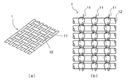
- FIG. 1 shows a plain weave base fabric (a) and a warp knitted base fabric (b) as examples of the base fabric 1 . With such a structure, irregularities are formed on the surface due to crossing and entanglement of the warp yarns 11 and the weft yarns 12 .
- FIG. 1(b) shows an independent chain knitting structure as a loop structure of the warp yarns 11, it is not limited to this, and a Denby knitting structure as shown in Japanese Patent Application Laid-Open No.
- the warp is not particularly limited as long as it is a material used in the relevant field, and is thermoplastic such as polyolefin resins such as polyethylene and polypropylene, polyester resins such as polyethylene terephthalate and polybutylene terephthalate, polyacrylic resins, and polyamide resins. Resins, regenerated fibers such as cuprammonium rayon and viscose rayon, and semi-synthetic fibers such as acetate and triacetate can be used. Of these, polyester fiber has a lower degree of elongation than other thermoplastic synthetic fibers such as polypropylene and nylon. It is possible to suppress fluffing and fraying.
- a fineness of 10 to 1000 denier, preferably 20 to 500 denier, and a number of warp yarns of 10 to 50 per inch provide a good balance of base fabric strength, hand tearability and elongation.
- the weft yarn is not particularly limited as long as it is a material used in the relevant field, and the same material as the above warp yarn can be used.
- the fiber form it is preferable to use a flat yarn in order to ensure hand-cutting properties and to suppress fluffing on the cut surface.
- a flat yarn can be obtained by thinning a film obtained by melt extruding a thermoplastic resin through a T-die or a circular die. The fineness is 30 to 1000 denier, preferably 50 to 500 denier, and the number of warp yarns is 5 to 40, preferably 8 to 30 per inch. Good balance with heat deterioration.
- the surface on which the first laminate layer described later is formed is the first surface, and the surface opposite to the first surface, on which the second laminate layer described later is formed, is the second surface. called a face.
- the first and second surfaces of the base fabric are subjected to a physical or chemical treatment, also called an anchoring treatment, in order to improve the bonding strength with the laminate layer and suppress the peeling of the laminate layer (referred to as "laminate peeling").
- surface treatment can be applied.
- Physical treatments include corona treatment, UV treatment, sputtering treatment, and the like, and chemical treatments include application of a selected resin such as organic titanium, isocyanate, polyethyleneimine, or polybutadiene.
- the laminate layer is formed by spreading the resin material on both sides of the base fabric.
- a thermoplastic resin is selected as the material for the warp and weft, it is preferable to select the same resin material as that of the laminate layer from the viewpoint of suppressing lamination peeling.
- the bonding strength between the laminate layer and the base fabric can be stably obtained by using a thermoplastic resin containing polyethylene for the laminate layer.
- the thickness of the laminate layer can be selected from the range of 5 to 300 ⁇ m.
- the first laminate layer which reflects the unevenness of the base fabric
- the second laminated layer which is flattened, can offset the unevenness of the base fabric. It is formed more than the thickness.
- FIG. 3 the first laminate layer 2 is formed on the first surface 1A where one warp 11 appears on the surface of the weft 12 of the base fabric 1, and the second laminate layer 3 is formed on the weft 12 of the base fabric 1. It shows a case where two warp yarns 11 appear on the surface of the second surface 1B.
- the resin material 24 is adhered to the base cloth 1 while being pressed against the cooling roll 26 together with the base cloth 1 by the press roll 25 made of rubber.
- the first laminate layer 2 having the matte surface 2A is formed on the first surface 1A where one warp 11 appears on the surface of the weft 12 of the base fabric 1, reflecting the unevenness of the base fabric in the process described later. It is preferable because it is easy to
- the resin material 24 is attached to the second surface 1B of the base fabric 1 by turning it over and using the same method as for the first surface 1A.
- the second laminate layer 3 having a smooth surface 3A can be formed as shown in FIG. 3(b).
- the outer surface of the second laminate layer 3 is not limited to the smooth surface 3A, and the releasability may be improved by forming a material layer to make the smooth surface, or performing a release treatment on the matte surface. .
- the mat surface 2A in contact with the press roll 25 has the warp 12 and the weft 11
- the first laminate layer 2 has an uneven surface 2B reflecting the unevenness of .
- the surface of the first laminate layer 2 becomes the uneven surface 2B, so that when the adhesive layer 6 shown in FIG. 4 is formed, the bonding area between the first laminate layer 2 and the adhesive layer 6 increases. , the adhesive residue can be effectively suppressed.
- unevenness derived from the mat roll 27 and unevenness derived from the warp yarn 12 and the weft yarn 11 are formed on the uneven surface 2B.
- the average depth of the recesses of the unevenness derived from the mat roll is preferably 1 ⁇ m or more and less than 10 ⁇ m so as not to affect the bonding surface of the adhesive layer 6 with the adherend.
- the average depth of the uneven recesses derived from the warp yarns 12 and the weft yarns 11 increases the bonding area with the adhesive layer 6, and does not affect the bonding surface of the adhesive layer 6 with the adherend. Therefore, the thickness is preferably 10 ⁇ m or more and 20 ⁇ m or less.
- the first surface 1A and the second surface 1B of the base fabric 1 can be subjected to physical or chemical surface treatment (anchor treatment).
- physical treatment include corona treatment, UV treatment, and sputtering treatment
- chemical treatment include a method of applying a resin selected from organotitanium, isocyanate, polyethyleneimine, polybutadiene, and the like. be done.
- FIG. 2 shows a mode of treatment by the corona treatment device 23 .
- FIG. 4 The structure of an adhesive tape according to one embodiment of the present invention is shown as a schematic cross-sectional view in FIG.
- a substrate 10 having laminated layers (a first laminated layer 2 and a second laminated layer 3) formed on both sides of a base fabric 1, a primer layer 4 on the first laminated layer side,
- An example in which an adhesive layer 6 is formed and a backing agent layer 5 is formed on the second laminate layer 3 side is shown.
- a primer layer 4 as shown in FIG. 4 can be formed in order to improve adhesion to the adhesive layer.
- Various elastomers e.g., copolymers of ethylene and vinyl acetate, chlorinated polypropylene, reaction products of styrene-butadiene copolymers and phenolic resins, butyl acrylate, vinyl acetate, acrylic acid amide, natural rubber or reaction product of synthetic rubber, etc.
- application of various primers and the like.
- the surface of the first laminate layer 2 may be modified by corona treatment, etching treatment, plasma treatment, sandblasting, or the like to form the primer layer 4, or the surface of the first laminate layer 2 may be corona-treated.
- the undercoat agent layer may be formed after modifying the composition with the above. The thickness of the undercoat layer is such that the irregularities in the first laminate layer 2 are reflected on the outer surface of the undercoat layer and the effect of suppressing adhesive residue due to the irregularities is not impaired.
- the pressure-sensitive adhesive layer 6 is formed as the outermost layer on the surface of the substrate 10 on which the first laminate layer is formed, either directly or via the primer layer 4 on the uneven first laminate layer 2. .
- the adhesive may be appropriately selected from known adhesive compositions so as to achieve the desired adhesive strength.
- the adhesive layer 6 contains a base polymer (referred to as an adhesive base polymer) as an adhesive component.
- the adhesive base polymer is not particularly limited, but an acrylic adhesive or a rubber adhesive can be used.
- acrylic adhesive examples include methyl (meth)acrylate, ethyl (meth)acrylate, isopropyl (meth)acrylate, n-butyl (meth)acrylate, 2-ethylhexyl (meth)acrylate, (Meth)acrylic ester monomers such as isooctyl (meth)acrylate, nonyl (meth)acrylate, and isononyl (meth)acrylate are the main components, and (meth)acrylic acid, crotonic acid, fumaric acid, and itaconic acid , (Anhydride) acrylic monomers containing functional groups such as maleic acid, vinyl acetate, acrylonitrile, styrene, 2-hydroxyethyl (meth)acrylate, 2-methylolethyl acrylamide, etc. are copolymerized as necessary. system adhesives.
- rubber-based adhesives include one or a combination of two or more elastomer components such as natural rubber, styrene-butadiene rubber, butyl rubber, isoprene rubber, butadiene rubber, and styrene-isoprene block copolymer, and rosin-based resins and terpenes. system resin, aliphatic petroleum resin, aromatic petroleum resin, copolymer petroleum resin, alicyclic petroleum resin, coumarone-indene resin, pure monomer resin, phenolic resin, xylene resin, etc.
- the resulting rubber-based pressure-sensitive adhesive is exemplified.
- the adhesive layer 6 can contain various additives known in the art in addition to the adhesive base polymer.
- various additives such as cross-linking agents, flame retardants, antioxidants, weathering agents, softeners, stabilizers, fillers, extenders, and reinforcing agents may be used singly or in combination of two or more. can contain.
- the thickness of the pressure-sensitive adhesive layer 6 can be appropriately set according to the purpose and each component of the pressure-sensitive adhesive used.
- the pressure-sensitive adhesive layer 6 is formed by coating directly on the first laminate layer 2, or after forming the undercoat layer 4 or applying a surface treatment, using various coating devices. Examples of coating apparatuses include roll coaters, die coaters, lip coaters, Meyer bar coaters, gravure coaters, and the like.
- ⁇ Backing agent layer> When wound as a tape, the surface of the second laminate layer that comes into contact with the pressure-sensitive adhesive layer 6 can be coated with various release agents as the backing agent layer 5 .
- Release agents include long-chain alkyl release agents (copolymers of stearyl acrylate and acrylic acid, vinyl acetate or acrylonitrile, copolymers of stearyl acrylamide and acrylonitrile or acrylic acid, stearyl vinyl ether and acrylic acid, anhydrous copolymers with maleic acid and acrylonitrile), and addition reaction type, condensation reaction type, cationic polymerization type, and radical polymerization type silicone release agents. These mold release agents can also be coated and formed by the various coating devices described above.
- Example 1 Using 30 denier polyester multifilament (24 threads/inch) as the warp and 300 denier high-density polyethylene flat yarn (17 threads/inch) as the weft, the warp as shown in FIG. A warp knitted fabric having an independent chain knit structure was knitted and used as a base fabric. Next, a laminate layer of polyethylene resin was formed on the back surface of the base fabric. First, the first surface 1A (the surface where one warp 11 appears on the surface of the weft 12) of the base fabric stretched between two rubber rolls is subjected to corona treatment, and then a polyethylene resin is melt extruded from a T-die.
- first surface 1A the surface where one warp 11 appears on the surface of the weft 12
- the first laminate layer 2 having the mat surface 2A.
- the second surface 1B is also subjected to corona treatment, and the polyethylene resin is melt-extruded from the T-die in the same manner as the first surface, and pressed against the mirror roll 18 with a rubber roll. to form a second laminate layer 3 having a smooth surface 3A.
- the first laminate layer 2 was formed with an uneven surface 2B reflecting the unevenness caused by the warp and weft.
- the thickness of the first laminate layer was 37 ⁇ m, and the thickness of the second laminate layer was 40 ⁇ m.
- the adhesive tape of Example 1 was produced by applying an acrylic adhesive to the uneven surface 2B of the first laminate layer 2 using a roll coater to form an adhesive layer 6 having a thickness of 35 ⁇ m. .
- Example 2 After applying corona treatment to the uneven surface 2B of the first laminate layer 2, an acrylic adhesive was applied using a roll coater to form the adhesive layer 6 in the same manner as in Example 1. No. 2 adhesive tape was produced.
- Example 3 After applying corona treatment to the uneven surface 2B of the first laminate layer 2, an undercoat layer 4 of ethylene-vinyl acetate copolymer is formed on the corona-treated surface, and then an acrylic adhesive is applied using a roll coater.
- a pressure-sensitive adhesive tape of Example 3 was produced in the same manner as in Example 1, except that the pressure-sensitive adhesive layer 6 was formed.
- Example 4 A plain weave fabric as shown in FIG. A pressure-sensitive adhesive tape of Example 4 was produced in the same manner as in Example 3, except that this was used as the base fabric. Among the unevenness formed on the surface of the first laminate layer, the average depth of the unevenness derived from the mat roll was 1.9 ⁇ m, and the average depth of the unevenness derived from the warp and weft was 13.5 ⁇ m. (Both are arithmetic mean values of 10-point measurements, measured using a white light interference microscope).
- Comparative example 1 Example except that the acrylic adhesive was applied to the smooth surface 3A side of the second laminate layer 3 of Example 1 to form an adhesive layer, and the acrylic adhesive was not applied to the first laminate side.
- An adhesive tape of Comparative Example 1 was produced in the same manner as in Example 1.
- Example 4 except that an acrylic adhesive was applied to the smooth surface 3A side of the second laminate layer 3 in Example 4 to form an adhesive layer, and the acrylic adhesive was not applied to the first laminate side.
- An adhesive tape of Comparative Example 2 was produced in the same manner as in Example 4.
- Comparative Examples 3-5 In the same manner as in Examples 1 to 3, except that the order of forming the first and second laminate layers in Examples 1 to 3 was reversed and the surface state of the first laminate layer was only matte, Comparative Examples 3 to 3 were prepared. 5 adhesive tape was produced.
- Test method ⁇ Adhesive residue on the adherend> Using an adhesive tape cut to a length of 300 mm in the warp stretching direction and a length of 24 mm in the weft stretching direction, it is attached to a test plate (SUS304 steel plate) used for adhesive strength measurement of JIS Z 0237 by the method described in the same standard. After that, it was allowed to stand for about 20 minutes in an environment with a temperature of 23 ⁇ 1° C. and a relative humidity of 50 ⁇ 5%.
- the adhesive tape was peeled off from the test plate based on the adhesive force measurement method of the same standard, and at that time, the area of adhesive residue (or adhesive residue due to breakage of the interface between the laminate layer and the adhesive layer) was measured, The percentage of the area of the peeled adhesive tape was calculated.
- the residual pressure-sensitive adhesive was also measured when the similarly prepared samples were allowed to stand in an environment of a temperature of 23 ⁇ 1° C. and a relative humidity of 50 ⁇ 5% for 3 days and 1 week. Table 1 shows the results.
- the pressure-sensitive adhesive tape according to the present invention can effectively suppress adhesive residue by having unevenness that reflects the unevenness of the surface of the base fabric on the adhesive-applied surface.
- by applying a surface treatment to the first laminate layer on which the adhesive is applied it is possible to provide an adhesive tape with almost no residual adhesive.
Landscapes
- Chemical & Material Sciences (AREA)
- Organic Chemistry (AREA)
- Engineering & Computer Science (AREA)
- Textile Engineering (AREA)
- Adhesive Tapes (AREA)
Abstract
Description
また、粘着テープは通常捲回したロール状で供給されるが、その場合、粘着剤層の形成される基材の反対面に倦回された粘着剤層が接触することになる。この反対面に粘着剤残りが発生すると、被着体の表面への粘着剤が不足し、隙間を生じたり、粘着力が低下したりする場合がある。また、粘着テープの粘着剤層の反対表面に粘着剤が残留することで、テープロールとしての取扱性が損なわれ、被着体に貼り付けた場合は粘着テープの使用目的を損なう場合がある。 When the adhesive remains, the surface of the adherend is contaminated with the adhesive, and the work of wiping off the adhesive remaining on the surface of the adherend causes a problem that the working efficiency of packing and curing is lowered. .
In addition, the adhesive tape is usually supplied in the form of a wound roll, in which case the wound adhesive layer comes into contact with the opposite side of the substrate on which the adhesive layer is formed. If the adhesive remains on the opposite surface, the adhesive may be insufficient on the surface of the adherend, resulting in gaps or reduced adhesive strength. In addition, the residual adhesive on the surface opposite to the adhesive layer of the adhesive tape impairs the handleability as a tape roll, and the purpose of use of the adhesive tape may be impaired when it is attached to an adherend.
すなわち、本発明は以下の態様を含むものである。 The present inventors have found that, in an adhesive tape, it is possible to suppress adhesive residue by forming unevenness on the surface of the laminate layer to which the adhesive layer is fixed.
That is, the present invention includes the following aspects.
前記基材の第一ラミネート層が形成された面側の最外層として形成される粘着剤層と、を有する粘着テープであって、
前記第一ラミネート層の前記基布とは反対側の面には、前記経糸および前記緯糸により生じる凹凸が形成されている、粘着テープ。 [1] A base fabric composed of warp and weft threads, a first laminate layer formed on a first surface of the base fabric, and a second laminate layer formed on a second surface of the base fabric, and a substrate having
and a pressure-sensitive adhesive layer formed as the outermost layer on the side of the substrate on which the first laminate layer is formed,
The pressure-sensitive adhesive tape, wherein unevenness caused by the warp and the weft is formed on the surface of the first laminate layer opposite to the base fabric.
[3] 前記第一ラミネート層と前記粘着剤層との間に下塗剤層が形成されている、[1]又は[2]に記載の粘着テープ。
[4] 前記第一ラミネート層の表面はコロナ処理が施されており、前記下塗剤層が該コロナ処理面に形成されている、[3]に記載の粘着テープ。
[5] 前記基布の前記第一及び第二の面がコロナ処理面である、[1]~[4]のいずれか1項に記載の粘着テープ。
[6] 前記第二ラミネート層の前記基布とは反対側の面に背面剤層が設けられている、[1]~[5]のいずれか1項に記載の粘着テープ。
[7] 前記経糸がマルチフィラメントであり、
前記緯糸がフラットヤーンである、[1]~[6]のいずれか1項に記載の粘着テープ。
[8] 前記経糸がポリエステル製のマルチフィラメントである、[1]~[7]のいずれか1項に記載の粘着テープ。
[9] 前記第一ラミネート層と前記第二ラミネート層がポリエチレンを含む熱可塑性樹脂から構成される、[1]~[8]のいずれか1項に記載の粘着テープ。
[10] 前記緯糸がポリエチレン製のフラットヤーンである、[9]に記載の粘着テープ。
[11] 前記基布は、前記経糸により形成されたループ構造に前記緯糸が挿入されたタテ編地である、[1]~[10]のいずれか1項に記載の粘着テープ。
[12] 前記ループ構造が独立鎖編みである、[11]に記載の粘着テープ。
「13」 前記第一ラミネート層が、前記基布の前記緯糸の表面に前記経糸が1本現れる第一の面に形成され、
前記第二ラミネート層が、前記基布の前記緯糸の表面に前記経糸が2本現れる第二の面に形成される、[11]又は[12]に記載の粘着テープ。 [2] The pressure-sensitive adhesive tape according to [1], wherein the surface of the second laminate layer opposite to the base fabric is a smooth surface.
[3] The pressure-sensitive adhesive tape according to [1] or [2], wherein a primer layer is formed between the first laminate layer and the pressure-sensitive adhesive layer.
[4] The pressure-sensitive adhesive tape of [3], wherein the surface of the first laminate layer is subjected to corona treatment, and the primer layer is formed on the corona-treated surface.
[5] The pressure-sensitive adhesive tape according to any one of [1] to [4], wherein the first and second surfaces of the base fabric are corona-treated surfaces.
[6] The pressure-sensitive adhesive tape according to any one of [1] to [5], wherein a backing agent layer is provided on the surface of the second laminate layer opposite to the base fabric.
[7] the warp is a multifilament;
The adhesive tape according to any one of [1] to [6], wherein the wefts are flat yarns.
[8] The pressure-sensitive adhesive tape according to any one of [1] to [7], wherein the warp is polyester multifilament.
[9] The pressure-sensitive adhesive tape according to any one of [1] to [8], wherein the first laminate layer and the second laminate layer are made of a thermoplastic resin containing polyethylene.
[10] The pressure-sensitive adhesive tape of [9], wherein the wefts are polyethylene flat yarns.
[11] The adhesive tape according to any one of [1] to [10], wherein the base fabric is a warp knitted fabric in which the weft is inserted into a loop structure formed by the warp.
[12] The pressure-sensitive adhesive tape of [11], wherein the loop structure is an independent chain stitch.
"13" The first laminate layer is formed on a first surface where one warp appears on the surface of the weft of the base fabric,
The pressure-sensitive adhesive tape according to [11] or [12], wherein the second laminate layer is formed on the second surface where two warp yarns appear on the surface of the weft yarns of the base fabric.
本発明の粘着テープに用いる基布には、長繊維の経糸および緯糸により構成される織布もしくは編布を用いることができる。織布の織組織は、平織、綾織、朱子織などから切断方向や強度など目的とする諸特性に応じて選択することができる。又、本発明の粘着テープに用いられる編布は経糸および緯糸の一方で連続したループを形成し、他方をこのループに挿通した組織を有する布であることが好ましい。経糸・緯糸のいずれにループを形成するかは、目的とする粘着テープの手切りによる切断方向に基づき決定すればよく、ループを形成する糸と垂直な方向を手切りの方向とすればよい。尚、以下で説明する経糸は、その伸長方向が粘着テープの長さ方向と略平行に配置される糸であり、緯糸は、伸長方向が粘着テープの長さ方向と略垂直に配置される糸をいう。
図1には、基布1の例として平織基布(a)とタテ編地基布(b)を示す。このような構造を有することで、経糸11と緯糸12の交差、絡み合いにより表面に凹凸が形成される。尚、図1(b)では経糸11によるループ構造として独立鎖編み構造を示しているが、これに限定されず、例えば特開2014-210998号公報に示されるようなデンビー編み構造でもよい。その他公知のループ構造も同様に使用することができる。
このような基布を経糸により形成されたループ構造に緯糸が挿入されたタテ編地を用い、該ループ構造を独立鎖編みとし、緯糸の表面に経糸が1本現れる第一の面に第一ラミネート層を形成し、緯糸の表面に経糸が2本現れる第二の面に第二ラミネート層を形成することにより、該第一の面において緯糸とラミネート層の接触面積を多くとることができ、ラミ剥がれを抑制することができる。 <Base fabric>
A woven or knitted fabric composed of long fiber warp and weft can be used as the base fabric for the adhesive tape of the present invention. The weave structure of the woven fabric can be selected from plain weave, twill weave, satin weave, etc., according to various desired characteristics such as cutting direction and strength. Further, the knitted fabric used for the adhesive tape of the present invention is preferably a fabric having a structure in which one of the warp and the weft forms a continuous loop and the other is inserted through the loop. Which of the warp and weft yarns the loops are to be formed in can be determined based on the intended cutting direction of the adhesive tape by manual cutting. The warp yarns described below are yarns whose elongation direction is arranged substantially parallel to the length direction of the adhesive tape, and the weft yarns are yarns whose elongation direction is arranged substantially perpendicular to the length direction of the adhesive tape. Say.
FIG. 1 shows a plain weave base fabric (a) and a warp knitted base fabric (b) as examples of the
Using a warp knitted fabric in which the weft is inserted into the loop structure formed by the warp of such a base fabric, the loop structure is made into an independent chain knitting, and the first surface on the first surface where one warp appears on the surface of the weft By forming the laminate layer and forming the second laminate layer on the second surface where two warp yarns appear on the surface of the weft yarn, the contact area between the weft yarn and the laminate layer can be increased on the first surface, It is possible to suppress lamination peeling.
経糸としては、当該分野において使用される材料であれば特に限定されず、ポリエチレン、ポリプロピレン等のポリオレフィン樹脂、ポリエチレンテレフタレートやポリブチレンテレフタレート等のポリエステル樹脂、ポリアクリル系樹脂、ポリアミド系樹脂などの熱可塑性樹脂や銅アンモニアレーヨンやビスコースレーヨン等の再生繊維、アセテートやトリアセテート等の半合成繊維が使用できる。これらの内、ポリエステル製繊維は、ポリプロピレンやナイロンなど他の熱可塑性合成繊維と比較して糸の伸度が低いため、粘着テープの幅方向に手切りする際、経糸の伸びを抑えて切断面の毛羽立ちやほつれを抑えることができる。
これらの繊維を経糸として用いる場合、繊維形態としてはマルチフィラメントを用いることが好ましい。粘着テープの縦方向の強度を維持しながら、適度な手切り性を確保することができる。繊度としては10~1000デニール、好ましくは20~500デニール、経糸の打ち込み本数としては1インチ当たり10~50本のものが、基布強度、手切り性、伸びのバランスにおいて良好である。 (warp)
The warp is not particularly limited as long as it is a material used in the relevant field, and is thermoplastic such as polyolefin resins such as polyethylene and polypropylene, polyester resins such as polyethylene terephthalate and polybutylene terephthalate, polyacrylic resins, and polyamide resins. Resins, regenerated fibers such as cuprammonium rayon and viscose rayon, and semi-synthetic fibers such as acetate and triacetate can be used. Of these, polyester fiber has a lower degree of elongation than other thermoplastic synthetic fibers such as polypropylene and nylon. It is possible to suppress fluffing and fraying.
When these fibers are used as warp yarns, it is preferable to use multifilaments as the fiber form. While maintaining the strength of the adhesive tape in the vertical direction, it is possible to ensure proper hand-tearability. A fineness of 10 to 1000 denier, preferably 20 to 500 denier, and a number of warp yarns of 10 to 50 per inch provide a good balance of base fabric strength, hand tearability and elongation.
緯糸としては、当該分野において使用される材料であれば特に限定されず、上記経糸と同様の材質が使用できる。繊維形態としては、手切り性を確保し、且つ、切断面での毛羽立ちを抑えるためにフラットヤーンを用いることが好ましい。フラットヤーンは、熱可塑性樹脂をTダイスや円形ダイスから溶融押出ししたフィルムを細幅に加工することにより得ることができる。繊度としては30~1000デニール、好ましくは50~500デニール、経糸の打ち込み本数としては1インチ当たり5~40本、好ましくは8~30本のものが、基材強度や手切り性、ラミネート時の熱劣化とのバランスが良好である。 (weft)
The weft yarn is not particularly limited as long as it is a material used in the relevant field, and the same material as the above warp yarn can be used. As for the fiber form, it is preferable to use a flat yarn in order to ensure hand-cutting properties and to suppress fluffing on the cut surface. A flat yarn can be obtained by thinning a film obtained by melt extruding a thermoplastic resin through a T-die or a circular die. The fineness is 30 to 1000 denier, preferably 50 to 500 denier, and the number of warp yarns is 5 to 40, preferably 8 to 30 per inch. Good balance with heat deterioration.
基布の第一の面及び第二の面には、ラミネート層との接合力を向上させてラミネート層の剥がれ(「ラミ剥がれ」という)を抑制するため、アンカー処理とも呼ばれる物理的または化学的な表面処理を施すことができる。物理的処理としてはコロナ処理、UV処理、スパッタリング処理等が挙げられ、化学的処理としては有機チタン系、イソシアネート系、ポリエチレンイミン系、ポリブタジエン系などか選んだ樹脂を塗布する処理が挙げられる。 For this base fabric, the surface on which the first laminate layer described later is formed is the first surface, and the surface opposite to the first surface, on which the second laminate layer described later is formed, is the second surface. called a face.
The first and second surfaces of the base fabric are subjected to a physical or chemical treatment, also called an anchoring treatment, in order to improve the bonding strength with the laminate layer and suppress the peeling of the laminate layer (referred to as "laminate peeling"). surface treatment can be applied. Physical treatments include corona treatment, UV treatment, sputtering treatment, and the like, and chemical treatments include application of a selected resin such as organic titanium, isocyanate, polyethyleneimine, or polybutadiene.
ラミネート層は、樹脂材料を基布の両面に延展することにより形成する。経糸や緯糸の材質として熱可塑性樹脂を選択する場合、ラミネート層と同種の樹脂材料を選択することがラミ剥がれを抑制する点で好ましい。例えばポリエチレン製の緯糸を用いる場合、ラミネート層にもポリエチレンを含む熱可塑性樹脂を用いることにより、ラミネート層と基布の接合力が安定して得られる。ラミネート層の厚みは5~300μmの範囲から選択することができる。特に、基布の凹凸が反映される第一ラミネート層は、基布の種類に応じて適宜最適の厚みとなるように、また、平坦化される第二ラミネート層は基布の凹凸を相殺できる厚み以上に形成される。 <Laminate layer>
The laminate layer is formed by spreading the resin material on both sides of the base fabric. When a thermoplastic resin is selected as the material for the warp and weft, it is preferable to select the same resin material as that of the laminate layer from the viewpoint of suppressing lamination peeling. For example, when polyethylene wefts are used, the bonding strength between the laminate layer and the base fabric can be stably obtained by using a thermoplastic resin containing polyethylene for the laminate layer. The thickness of the laminate layer can be selected from the range of 5 to 300 μm. In particular, the first laminate layer, which reflects the unevenness of the base fabric, has an optimum thickness according to the type of the base fabric, and the second laminated layer, which is flattened, can offset the unevenness of the base fabric. It is formed more than the thickness.
まず、経糸11および緯糸12からなる基布1の第一の面1Aに、図2に示すように押出ラミネータ20を用い、押出機21からTダイ22を介して樹脂材料24を供給し、この樹脂材料24をゴム製のプレスロール25により基布1と共に冷却ロール26に押し当てながら基布1と貼り合わせる。ここで、第一の面1Aに樹脂材料24を貼り合わせる際、冷却ロール26として表面に凹凸加工が施されたマットロール27を用いることにより、図3(a)に示すように、編地の場合には、マット面2Aを有する第一ラミネート層2が基布1の緯糸12の表面に経糸11が1本現れる第一の面1Aに形成することが後述の工程で基布の凹凸を反映しやすいことから好ましい。 A method of forming a laminate layer will be described with reference to FIGS. 2 and 3. FIG. 3, the
First, using an
上記のように形成した第一ラミネート層2の表面には、粘着剤層との密着性を改善するために、図4に示すような下塗剤層4を形成することができる。下塗剤としては、各種エラストマー(例えば、エチレンと酢酸ビニルとの共重合体、塩素化ポリプロピレン、スチレン・ブタジエン共重合体とフェノール樹脂の反応物、ブチルアクリレート、酢酸ビニル、アクリル酸アミド、天然ゴムまたは合成ゴムの反応物等)の塗布、各種プライマーの塗布などが挙げられる。また、第一ラミネート層2の表面をコロナ処理、エッチング処理、プラズマ処理、サンドブラスト処理等で改質することにより下塗剤層4を形成してもよいし、第一ラミネート層2の表面をコロナ処理等で改質した後、下塗剤層を形成してもよい。下塗剤層の厚みは、第一ラミネート層2における凹凸が下塗剤層の外表面に反映され、該凹凸による粘着剤残り抑制効果を損なわない範囲の膜厚とする。 <Undercoat layer>
On the surface of the
このように、凹凸の形成された第一ラミネート層2に直接又は下塗剤層4を介して粘着剤層6が基材10の第一ラミネート層の形成される面側の最外層として形成される。粘着剤としては、公知の粘着剤組成物から所望の粘着力になるように適宜選択して使用すればよい。粘着剤層6は、粘着剤成分としてのベースポリマー(粘着剤ベースポリマーという)を含む。前記粘着剤ベースポリマーは特に限定されないが、アクリル系粘着剤やゴム系粘着剤を用いることができる。前記アクリル系粘着剤としては、例えば(メタ)アクリル酸メチル、(メタ)アクリル酸エチル、(メタ)アクリル酸イソプロピル、(メタ)アクリル酸n-ブチル、(メタ)アクリル酸2-エチルへキシル、(メタ)アクリル酸イソオクチル、(メタ)アクリル酸ノニル、(メタ)アクリル酸イソノニル等の(メタ)アクリル酸エステルモノマーを主成分とし、これに(メタ)アクリル酸、クロトン酸、フマル酸、イタコン酸、(無水)マレイン酸等の官能基を含むモノマーや酢酸ビニル、アクリロニトリル、スチレン、(メタ)アクリル酸2-ヒドロキシエチル、2-メチロールエチルアクリルアミド等を必要に応じて共重合させることにより得られるアクリル系粘着剤が挙げられる。 <Adhesive layer>
In this way, the pressure-
テープとして巻き回しする際に、粘着剤層6と接する第二ラミネート層側表面は、背面剤層5として各種離型剤を塗布することができる。離型剤としては、長鎖アルキル系離型剤(ステアリルアクリレートとアクリル酸、酢酸ビニルまたはアクリロニトリルとの共重合物、ステアリルアクリルアミドとアクリロニトリルやアクリル酸との共重合物、ステアリルビニルエーテルとアクリル酸、無水マレイン酸、アクリロニトリルとの共重合物)や、付加反応型、縮合反応型、カチオン重合型、ラジカル重合型のシリコーン系離型剤等が挙げられる。
これらの離型剤も、上記の各種塗布装置により塗布形成することができる。 <Backing agent layer>
When wound as a tape, the surface of the second laminate layer that comes into contact with the pressure-
These mold release agents can also be coated and formed by the various coating devices described above.
経糸として30デニールのポリエステルマルチフィラメント(打ち込み本数24本/インチ)、緯糸として300デニールの高密度ポリエチレンフラットヤーン(打ち込み本数17本/インチ)を用い、図1(b)に示すような、経糸が独立鎖編み構造となるタテ編地を編成し、基布として使用した。
次に、基布の裏表面にポリエチレン樹脂のラミネート層を形成した。まず、2つのゴムロール間に張架された基布の第一の面1A(緯糸12の表面に経糸11が1本現れる面))にコロナ処理を施した後、Tダイからポリエチレン樹脂を溶融押し出しし、ゴムロールによりマットロール17に押し付けて、マット面2Aを有する第一ラミネート層2を形成した。次に、表裏を反転させた後、第二の面1Bにもコロナ処理を施した後、第一の面と同様の方法でTダイからポリエチレン樹脂を溶融押し出しし、ゴムロールによりミラーロール18に押し付けて平滑面3Aを有する第二ラミネート層3を形成した。第一ラミネート層2には、経糸および緯糸による凹凸を反映した凹凸面2Bが形成されていた。第一ラミネート層の厚みは37μm、第二ラミネート層の厚みは40μmであった。第一ラミネート層の表面に形成された凹凸のうち、マットロールに由来する凹凸の凹部の平均深さは3.0μm、経糸および緯糸に由来する凹凸の凹部の平均深さは12.4μmであった(共に10点計測の算術平均値。白色干渉顕微鏡を用いて測定した)。次に、第一ラミネート層2の凹凸面2Bに、ロールコーターを用いてアクリル系粘着剤を塗布し、厚さ35μmの粘着剤層6を形成することにより、実施例1の粘着テープを作製した。 (Example 1)
Using 30 denier polyester multifilament (24 threads/inch) as the warp and 300 denier high-density polyethylene flat yarn (17 threads/inch) as the weft, the warp as shown in FIG. A warp knitted fabric having an independent chain knit structure was knitted and used as a base fabric.
Next, a laminate layer of polyethylene resin was formed on the back surface of the base fabric. First, the
第一ラミネート層2の凹凸面2Bにコロナ処理を施した後、ロールコーターを用いてアクリル系粘着剤を塗布して粘着剤層6を形成したこと以外は実施例1と同様にして、実施例2の粘着テープを作製した。 (Example 2)
After applying corona treatment to the
第一ラミネート層2の凹凸面2Bにコロナ処理を施した後、コロナ処理面にエチレン-酢酸ビニル共重合体の下塗剤層4を形成し、その後ロールコーターを用いてアクリル系粘着剤を塗布して粘着剤層6を形成したこと以外は実施例1と同様にして、実施例3の粘着テープを作製した。 (Example 3).
After applying corona treatment to the
経糸として30デニールのポリエステルマルチフィラメント(打ち込み本数78本/インチ)を、緯糸として100デニールのポリエステルマルチフィラメント(打ち込み本数18本/インチ)を用いて図1(a)に示す様な平織地を織成し、これを基布として使用したこと以外は実施例3と同様にして、実施例4の粘着テープを作製した。第一ラミネート層の表面に形成された凹凸のうち、マットロールに由来する凹凸の凹部の平均深さは1.9μm、経糸および緯糸に由来する凹凸の凹部の平均深さは13.5μmであった(共に10点計測の算術平均値。白色干渉顕微鏡を用いて測定した)。 (Example 4)
A plain weave fabric as shown in FIG. A pressure-sensitive adhesive tape of Example 4 was produced in the same manner as in Example 3, except that this was used as the base fabric. Among the unevenness formed on the surface of the first laminate layer, the average depth of the unevenness derived from the mat roll was 1.9 μm, and the average depth of the unevenness derived from the warp and weft was 13.5 μm. (Both are arithmetic mean values of 10-point measurements, measured using a white light interference microscope).
実施例1の第二ラミネート層3の平滑面3A側にアクリル系粘着剤を塗布して粘着剤層を形成し、第一ラミネート側にはアクリル系粘着剤を塗布しなかったこと以外は実施例1と同様にして、比較例1の粘着テープを作製した。 (Comparative example 1)
Example except that the acrylic adhesive was applied to the
実施例4の第二ラミネート層3の平滑面3A側にアクリル系粘着剤を塗布して粘着剤層を形成し、第一ラミネート側にはアクリル系粘着剤を塗布しなかったこと以外は実施例4と同様にして、比較例2の粘着テープを作製した。
(比較例3~5)
実施例1~3における第一及び第二ラミネート層の形成順序を逆とし、第一ラミネート層の表面状態をマット状のみとした以外は実施例1~3とそれぞれ同様にして、比較例3~5の粘着テープを作製した。 (Comparative example 2)
Example 4 except that an acrylic adhesive was applied to the
(Comparative Examples 3-5)
In the same manner as in Examples 1 to 3, except that the order of forming the first and second laminate layers in Examples 1 to 3 was reversed and the surface state of the first laminate layer was only matte, Comparative Examples 3 to 3 were prepared. 5 adhesive tape was produced.
<被着体への糊残り>
経糸の延伸方向の長さ300mm、緯糸の延伸方向の長さ24mmにカットした粘着テープを用い、JIS Z 0237の粘着力測定に使用する試験板(SUS304鋼板)に同規格に記載の方法で張り付けた後、温度23±1℃、相対湿度50±5%の環境下に20分間程度静置した。その後、同規格の粘着力測定方法に基づいて粘着テープを試験板から引き剥がし、その際、粘着剤残り(又はラミネート層と粘着剤層境界面の破壊による粘着剤残り)の面積を測定し、引き剥がした粘着テープの面積中の割合を算出した。又、同様に製作したサンプルを温度23±1℃、相対湿度50±5%の環境下に3日間および1週間静置した場合についても粘着剤残りを測定した。結果を表1に示す。 "Evaluation method"
<Adhesive residue on the adherend>
Using an adhesive tape cut to a length of 300 mm in the warp stretching direction and a length of 24 mm in the weft stretching direction, it is attached to a test plate (SUS304 steel plate) used for adhesive strength measurement of JIS Z 0237 by the method described in the same standard. After that, it was allowed to stand for about 20 minutes in an environment with a temperature of 23±1° C. and a relative humidity of 50±5%. After that, the adhesive tape was peeled off from the test plate based on the adhesive force measurement method of the same standard, and at that time, the area of adhesive residue (or adhesive residue due to breakage of the interface between the laminate layer and the adhesive layer) was measured, The percentage of the area of the peeled adhesive tape was calculated. In addition, the residual pressure-sensitive adhesive was also measured when the similarly prepared samples were allowed to stand in an environment of a temperature of 23±1° C. and a relative humidity of 50±5% for 3 days and 1 week. Table 1 shows the results.


11 経糸
12 緯糸
1A 第一の面
1B 第二の面
2 第一ラミネート層
2A マット面
2B 凹凸面
3 第二ラミネート層
3A 平滑面
4 下塗り剤層
5 背面剤層
6 粘着剤層
10 基材
20 押出ラミネータ
21 押出機
22 Tダイ
23 コロナ処理装置
24 樹脂材料
25 プレスロール(ゴム製)
26 冷却ロール
27 マットロール
28 平滑ロール 1
26
Claims (13)
- 経糸及び緯糸により構成される基布と、前記基布の第一の面に形成される第一ラミネート層と、前記基布の第二の面に形成される第二ラミネート層と、を有する基材と、
前記基材の第一ラミネート層が形成された面側の最外層として形成される粘着剤層と、を有する粘着テープであって、
前記第一ラミネート層の前記基布とは反対側の面には、前記経糸および前記緯糸により生じる凹凸が形成されている、粘着テープ。 A base having a base fabric composed of warp and weft, a first laminate layer formed on a first surface of the base fabric, and a second laminate layer formed on a second surface of the base fabric. material and
and a pressure-sensitive adhesive layer formed as the outermost layer on the side of the substrate on which the first laminate layer is formed,
The pressure-sensitive adhesive tape, wherein unevenness caused by the warp and the weft is formed on the surface of the first laminate layer opposite to the base fabric. - 前記第二ラミネート層の前記基布とは反対側の面は平滑面である、請求項1に記載の粘着テープ。 The pressure-sensitive adhesive tape according to claim 1, wherein the surface of the second laminate layer opposite to the base fabric is a smooth surface.
- 前記第一ラミネート層と前記粘着剤層との間に下塗剤層が形成されている、請求項1または2に記載の粘着テープ。 The pressure-sensitive adhesive tape according to claim 1 or 2, wherein a primer layer is formed between the first laminate layer and the pressure-sensitive adhesive layer.
- 前記第一ラミネート層の表面はコロナ処理が施されており、前記下塗剤層が該コロナ処理面に形成されている、請求項3に記載の粘着テープ。 The pressure-sensitive adhesive tape according to claim 3, wherein the surface of the first laminate layer is subjected to corona treatment, and the primer layer is formed on the corona-treated surface.
- 前記基布の前記第一及び第二の面がコロナ処理面である、請求項1~4のいずれか1項に記載の粘着テープ。 The adhesive tape according to any one of claims 1 to 4, wherein the first and second surfaces of the base fabric are corona-treated surfaces.
- 前記第二ラミネート層の前記基布とは反対側の面に背面剤層が設けられている、請求項1~5のいずれか1項に記載の粘着テープ The adhesive tape according to any one of claims 1 to 5, wherein a backing agent layer is provided on the surface of the second laminate layer opposite to the base fabric.
- 前記経糸がマルチフィラメントであり、
前記緯糸がフラットヤーンである、請求項1~6のいずれか1項に記載の粘着テープ。 The warp is a multifilament,
The adhesive tape according to any one of claims 1 to 6, wherein said weft yarn is a flat yarn. - 前記経糸がポリエステル製のマルチフィラメントである、請求項1~7のいずれか1項に記載の粘着テープ。 The adhesive tape according to any one of claims 1 to 7, wherein the warp yarns are polyester multifilaments.
- 前記第一ラミネート層と前記第二ラミネート層がポリエチレンを含む熱可塑性樹脂から構成される、請求項1~8のいずれか1項に記載の粘着テープ。 The adhesive tape according to any one of claims 1 to 8, wherein the first laminate layer and the second laminate layer are made of a thermoplastic resin containing polyethylene.
- 前記緯糸がポリエチレン製のフラットヤーンである、請求項9に記載の粘着テープ。 The adhesive tape according to claim 9, wherein the wefts are polyethylene flat yarns.
- 前記基布は、前記経糸により形成されたループ構造に前記緯糸が挿入されたタテ編地である、請求項1~10のいずれか1項に記載の粘着テープ。 The adhesive tape according to any one of claims 1 to 10, wherein the base fabric is a warp knitted fabric in which the weft is inserted into a loop structure formed by the warp.
- 前記ループ構造が独立鎖編みである、請求項11に記載の粘着テープ。 The adhesive tape according to claim 11, wherein the loop structure is an independent chain stitch.
- 前記第一ラミネート層が、前記基布の前記緯糸の表面に前記経糸が1本現れる第一の面に形成され、
前記第二ラミネート層が、前記基布の前記緯糸の表面に前記経糸が2本現れる第二の面に形成される、請求項11又は12に記載の粘着テープ。 The first laminate layer is formed on a first surface where one warp appears on the surface of the weft of the base fabric,
13. The pressure-sensitive adhesive tape according to claim 11 or 12, wherein the second laminate layer is formed on the second surface where two warp threads appear on the surface of the weft threads of the base fabric.
Priority Applications (4)
| Application Number | Priority Date | Filing Date | Title |
|---|---|---|---|
| CN202180095674.2A CN116981745A (en) | 2021-03-15 | 2021-04-27 | Adhesive tape |
| KR1020237031279A KR20230146062A (en) | 2021-03-15 | 2021-04-27 | adhesive tape |
| JP2023506710A JP7451824B2 (en) | 2021-03-15 | 2021-04-27 | Adhesive tape |
| EP21931644.5A EP4309891A1 (en) | 2021-03-15 | 2021-04-27 | Pressure-sensitive adhesive tape |
Applications Claiming Priority (2)
| Application Number | Priority Date | Filing Date | Title |
|---|---|---|---|
| JP2021041476 | 2021-03-15 | ||
| JP2021-041476 | 2021-03-15 |
Publications (1)
| Publication Number | Publication Date |
|---|---|
| WO2022195899A1 true WO2022195899A1 (en) | 2022-09-22 |
Family
ID=83322173
Family Applications (1)
| Application Number | Title | Priority Date | Filing Date |
|---|---|---|---|
| PCT/JP2021/016843 WO2022195899A1 (en) | 2021-03-15 | 2021-04-27 | Pressure-sensitive adhesive tape |
Country Status (6)
| Country | Link |
|---|---|
| EP (1) | EP4309891A1 (en) |
| JP (1) | JP7451824B2 (en) |
| KR (1) | KR20230146062A (en) |
| CN (1) | CN116981745A (en) |
| TW (1) | TW202237773A (en) |
| WO (1) | WO2022195899A1 (en) |
Citations (9)
| Publication number | Priority date | Publication date | Assignee | Title |
|---|---|---|---|---|
| JPH07247466A (en) * | 1994-03-10 | 1995-09-26 | Toho Seni Kk | Reinforcing knit cloth for tacky adhesive tape and tacky adhesive tape produced by using the reinforcing knit cloth |
| JPH11335942A (en) * | 1998-06-01 | 1999-12-07 | Aoyama Sangyo Kk | Base fabric for adhesive tape and processed fabric for adhesive tape |
| JP2000314062A (en) * | 1999-04-28 | 2000-11-14 | Aoyama Sangyo Kk | Base fabric for laminated tape |
| JP2002294189A (en) | 2001-03-30 | 2002-10-09 | Teraoka Seisakusho:Kk | Pressure-sensitive adhesive knit fabric tape |
| JP2003253543A (en) * | 2002-03-01 | 2003-09-10 | Teijin Ltd | Fabric for producing readily tearable adhesive tape and the resulting adhesive tape |
| JP2009138031A (en) * | 2007-12-03 | 2009-06-25 | Teraoka Seisakusho:Kk | Fabric-backed pressure-sensitive adhesive tape |
| JP2012017415A (en) * | 2010-07-08 | 2012-01-26 | Sekisui Chem Co Ltd | Fabric adhesive tape |
| JP2012036516A (en) * | 2010-08-04 | 2012-02-23 | Sumitomo Wiring Syst Ltd | Fabric for binding tape, and binding tape |
| JP2014210998A (en) | 2013-04-19 | 2014-11-13 | 青山産業株式会社 | Ground fabric for laminate tape and laminate tape using the ground fabric |
-
2021
- 2021-04-27 KR KR1020237031279A patent/KR20230146062A/en unknown
- 2021-04-27 WO PCT/JP2021/016843 patent/WO2022195899A1/en active Application Filing
- 2021-04-27 JP JP2023506710A patent/JP7451824B2/en active Active
- 2021-04-27 TW TW110115020A patent/TW202237773A/en unknown
- 2021-04-27 EP EP21931644.5A patent/EP4309891A1/en active Pending
- 2021-04-27 CN CN202180095674.2A patent/CN116981745A/en active Pending
Patent Citations (9)
| Publication number | Priority date | Publication date | Assignee | Title |
|---|---|---|---|---|
| JPH07247466A (en) * | 1994-03-10 | 1995-09-26 | Toho Seni Kk | Reinforcing knit cloth for tacky adhesive tape and tacky adhesive tape produced by using the reinforcing knit cloth |
| JPH11335942A (en) * | 1998-06-01 | 1999-12-07 | Aoyama Sangyo Kk | Base fabric for adhesive tape and processed fabric for adhesive tape |
| JP2000314062A (en) * | 1999-04-28 | 2000-11-14 | Aoyama Sangyo Kk | Base fabric for laminated tape |
| JP2002294189A (en) | 2001-03-30 | 2002-10-09 | Teraoka Seisakusho:Kk | Pressure-sensitive adhesive knit fabric tape |
| JP2003253543A (en) * | 2002-03-01 | 2003-09-10 | Teijin Ltd | Fabric for producing readily tearable adhesive tape and the resulting adhesive tape |
| JP2009138031A (en) * | 2007-12-03 | 2009-06-25 | Teraoka Seisakusho:Kk | Fabric-backed pressure-sensitive adhesive tape |
| JP2012017415A (en) * | 2010-07-08 | 2012-01-26 | Sekisui Chem Co Ltd | Fabric adhesive tape |
| JP2012036516A (en) * | 2010-08-04 | 2012-02-23 | Sumitomo Wiring Syst Ltd | Fabric for binding tape, and binding tape |
| JP2014210998A (en) | 2013-04-19 | 2014-11-13 | 青山産業株式会社 | Ground fabric for laminate tape and laminate tape using the ground fabric |
Also Published As
| Publication number | Publication date |
|---|---|
| JPWO2022195899A1 (en) | 2022-09-22 |
| JP7451824B2 (en) | 2024-03-18 |
| EP4309891A1 (en) | 2024-01-24 |
| KR20230146062A (en) | 2023-10-18 |
| CN116981745A (en) | 2023-10-31 |
| TW202237773A (en) | 2022-10-01 |
Similar Documents
| Publication | Publication Date | Title |
|---|---|---|
| KR100731396B1 (en) | Pressure-sensitive adhesive tape or sheet | |
| KR20050086952A (en) | Adhesive tape | |
| JP2020019923A (en) | Adhesive article | |
| JP4319169B2 (en) | Masking adhesive tape and masker using the same | |
| KR101946322B1 (en) | Laminated film | |
| JP3555880B2 (en) | Knitted fabric adhesive tape | |
| TW202405112A (en) | Adhesive article | |
| WO2022195899A1 (en) | Pressure-sensitive adhesive tape | |
| JPWO2006077662A1 (en) | Retroreflective adhesive sheet | |
| JP7431321B2 (en) | Adhesive tape | |
| KR101161871B1 (en) | Double-sided adhesive tape for attaching rubbing cloth and rubbing sheet attached with the tape for winding around a roll | |
| KR102033651B1 (en) | Multilayer adhesive bonding element | |
| JP2004099805A (en) | Pressure-sensitive adhesive sheet | |
| JP3205388U (en) | Adhesive tape laminate | |
| JP4142965B2 (en) | Adhesive sheet with improved hand cutting | |
| JPH10316944A (en) | Adhesive tape or sheet | |
| JP2007063512A (en) | Pressure-sensitive adhesive sheet improved in cutting property by hand | |
| WO2024101424A1 (en) | Adhesive body | |
| KR20210147623A (en) | Lamination method and system of industrial adhesive without substrate | |
| WO2022075201A1 (en) | Pressure-sensitive adhesive tape | |
| WO2024101426A1 (en) | Wound body of adhesive body and method for producing same | |
| US20220332987A1 (en) | Method for applying a threadlike adhesive body, and temporary-support-supported threadlike adhesive body | |
| JP2007063511A (en) | Pressure-sensitive adhesive sheet improved in cutting property by hand | |
| JP2006137899A (en) | Weathering-resistant pressure-sensitive adhesive sheet | |
| JP2003342539A (en) | Retroreflective adhesive sheet |
Legal Events
| Date | Code | Title | Description |
|---|---|---|---|
| 121 | Ep: the epo has been informed by wipo that ep was designated in this application |
Ref document number: 21931644 Country of ref document: EP Kind code of ref document: A1 |
|
| ENP | Entry into the national phase |
Ref document number: 2023506710 Country of ref document: JP Kind code of ref document: A |
|
| ENP | Entry into the national phase |
Ref document number: 20237031279 Country of ref document: KR Kind code of ref document: A |
|
| WWE | Wipo information: entry into national phase |
Ref document number: 202180095674.2 Country of ref document: CN Ref document number: 1020237031279 Country of ref document: KR |
|
| WWE | Wipo information: entry into national phase |
Ref document number: 2021931644 Country of ref document: EP |
|
| NENP | Non-entry into the national phase |
Ref country code: DE |
|
| ENP | Entry into the national phase |
Ref document number: 2021931644 Country of ref document: EP Effective date: 20231016 |