WO2022191222A1 - 胆管チップ及びその使用 - Google Patents
胆管チップ及びその使用 Download PDFInfo
- Publication number
- WO2022191222A1 WO2022191222A1 PCT/JP2022/010191 JP2022010191W WO2022191222A1 WO 2022191222 A1 WO2022191222 A1 WO 2022191222A1 JP 2022010191 W JP2022010191 W JP 2022010191W WO 2022191222 A1 WO2022191222 A1 WO 2022191222A1
- Authority
- WO
- WIPO (PCT)
- Prior art keywords
- cells
- channel
- substrate
- bile duct
- membrane
- Prior art date
- Legal status (The legal status is an assumption and is not a legal conclusion. Google has not performed a legal analysis and makes no representation as to the accuracy of the status listed.)
- Ceased
Links
Images











Classifications
-
- C—CHEMISTRY; METALLURGY
- C12—BIOCHEMISTRY; BEER; SPIRITS; WINE; VINEGAR; MICROBIOLOGY; ENZYMOLOGY; MUTATION OR GENETIC ENGINEERING
- C12M—APPARATUS FOR ENZYMOLOGY OR MICROBIOLOGY; APPARATUS FOR CULTURING MICROORGANISMS FOR PRODUCING BIOMASS, FOR GROWING CELLS OR FOR OBTAINING FERMENTATION OR METABOLIC PRODUCTS, i.e. BIOREACTORS OR FERMENTERS
- C12M1/00—Apparatus for enzymology or microbiology
-
- C—CHEMISTRY; METALLURGY
- C12—BIOCHEMISTRY; BEER; SPIRITS; WINE; VINEGAR; MICROBIOLOGY; ENZYMOLOGY; MUTATION OR GENETIC ENGINEERING
- C12M—APPARATUS FOR ENZYMOLOGY OR MICROBIOLOGY; APPARATUS FOR CULTURING MICROORGANISMS FOR PRODUCING BIOMASS, FOR GROWING CELLS OR FOR OBTAINING FERMENTATION OR METABOLIC PRODUCTS, i.e. BIOREACTORS OR FERMENTERS
- C12M21/00—Bioreactors or fermenters specially adapted for specific uses
- C12M21/08—Bioreactors or fermenters specially adapted for specific uses for producing artificial tissue or for ex-vivo cultivation of tissue
-
- C—CHEMISTRY; METALLURGY
- C12—BIOCHEMISTRY; BEER; SPIRITS; WINE; VINEGAR; MICROBIOLOGY; ENZYMOLOGY; MUTATION OR GENETIC ENGINEERING
- C12M—APPARATUS FOR ENZYMOLOGY OR MICROBIOLOGY; APPARATUS FOR CULTURING MICROORGANISMS FOR PRODUCING BIOMASS, FOR GROWING CELLS OR FOR OBTAINING FERMENTATION OR METABOLIC PRODUCTS, i.e. BIOREACTORS OR FERMENTERS
- C12M23/00—Constructional details, e.g. recesses, hinges
- C12M23/02—Form or structure of the vessel
- C12M23/16—Microfluidic devices; Capillary tubes
-
- C—CHEMISTRY; METALLURGY
- C12—BIOCHEMISTRY; BEER; SPIRITS; WINE; VINEGAR; MICROBIOLOGY; ENZYMOLOGY; MUTATION OR GENETIC ENGINEERING
- C12M—APPARATUS FOR ENZYMOLOGY OR MICROBIOLOGY; APPARATUS FOR CULTURING MICROORGANISMS FOR PRODUCING BIOMASS, FOR GROWING CELLS OR FOR OBTAINING FERMENTATION OR METABOLIC PRODUCTS, i.e. BIOREACTORS OR FERMENTERS
- C12M29/00—Means for introduction, extraction or recirculation of materials, e.g. pumps
- C12M29/04—Filters; Permeable or porous membranes or plates, e.g. dialysis
Definitions
- the present invention relates to a bile duct chip and its use. More specifically, the present invention relates to a bile duct chip, a method for manufacturing the bile duct chip, and a method for evaluating bile acid dynamics.
- This application claims priority from provisional application US63/158,891 filed March 10, 2021 in the United States, the contents of which are hereby incorporated by reference.
- hepatocytes synthesize bile acids.
- the synthesized bile acids are excreted into the bile canaliculi via hepatic transporters and flow into the intrahepatic bile ducts. Bile acids are then secreted into the gastrointestinal tract via the extrahepatic bile duct. Bile acids play important roles such as lipid metabolism, but excessive amounts of bile acids are toxic to hepatocytes. Therefore, when bile acid kinetics is inhibited and bile acid accumulates in hepatocytes, cholestatic liver injury is induced. Cholestatic liver disease is a disease associated with the risk of cirrhosis and liver cancer.
- cholestasis Approximately 40% of drug-induced liver injury is classified as cholestasis. Also, some gene mutations are known to cause cholestatic liver injury. In order to study cholestatic liver injury and develop therapeutic agents, a model that can reproduce bile acid dynamics is necessary. A model that can reproduce bile acid kinetics is also important for identifying drug candidate compounds that cause cholestatic liver injury at an early stage of drug development.
- hepatocytes cultured in 2D cell culture plates are used as an in vitro liver model.
- the 2D hepatocyte model has bile canaliculi between adjacent hepatocytes and can reproduce bile flow from hepatocytes to bile canaliculi.
- the 2D hepatocyte model does not have intrahepatic bile ducts composed of cholangiocytes, bile flow from bile canaliculi to intrahepatic bile ducts cannot be reproduced. Therefore, it is difficult to reproduce bile acid dynamics in vitro with a 2D hepatocyte model.
- Organ-on-a-chip technology is a technology that can reproduce some of the functions of organs in vitro by culturing cells in a fluid device (see Patent Document 1, for example).
- the performance of Organ-on-a-chip is greatly influenced by the cells to be loaded and the material used for the fluidic device.
- Human primary cultured hepatocytes are most widely used as hepatocytes to be loaded on Liver-on-a-chip.
- it is essential to use not only human primary cultured hepatocytes but also non-parenchymal cells such as bile duct epithelial cells.
- An object of the present invention is to provide a bile duct tip having a tubular bile duct-like structure.
- a bile duct chip comprising a membrane capable of mass transfer from one surface to the other surface, a first substrate having a recess forming a first channel, and a recess forming a second channel. and a second substrate, wherein the first substrate, the film, and the second substrate are stacked in this order, and the concave portion of the first substrate has an opening that extends from one surface of the film.
- the first substrate, the film, and the second substrate are laminated in this order;
- the concave portion of the second substrate has an opening facing the other surface of the film, and the one surface of the film forms part of the first flow path. and the other surface of the membrane forms part of the second flow path, and the first flow path and the second flow path communicate through the membrane.
- 1. comprising the steps of: seeding bile duct epithelial cells in the first channel; and introducing a medium containing a lumen-enhancing factor into the first channel. [6] to [5], wherein the lumen-forming factor is at least one factor selected from the group consisting of Delta Like Canonical Notch Ligand 1 (DLL1) and Delta Like Canonical Notch Ligand 4 (DLL4); Method of manufacture as described.
- DLL1 Delta Like Canonical Notch Ligand 1
- DLL4 Delta Like Canonical Notch Ligand 4
- a method for evaluating bile acid kinetics comprising: a membrane capable of mass transfer from one side to the other side; a first substrate having recesses forming a first channel; a second substrate having a concave portion formed thereon, wherein the first substrate, the film, and the second substrate are laminated in this order, and the concave portion of the first substrate has an opening portion corresponding to the film; The concave portion of the second substrate has an opening facing the other surface of the film, and the one surface of the film forms part of the first flow path.
- Bile duct epithelial cells are arranged on the surface of the inner wall of the first channel to form a tube
- liver cells are arranged in the second channel.
- the bile acid kinetics are bile acid kinetics and one or more factors selected from the group consisting of in vivo compounds other than bile acids, drugs, and pathogens.
- a bile duct tip having a tubular bile duct-like structure can be provided.
- FIG. 1 is a schematic diagram showing the structure of an intrahepatic bile duct in vivo.
- FIG. 2(a) is a plan view (photograph) of a bile duct chip according to one embodiment.
- FIG. 2(b) is a perspective view showing the structure of a bile duct tip according to one embodiment.
- FIG.2(c) is the schematic diagram which expanded the part enclosed with the square of FIG.2(b).
- FIG. 3 shows cross-sectional fluorescent microscope images taken 1, 2, 4, and 10 days after the GFP-expressing HuCCT1 cells were cultured inside the channel of the fluidic device in Experimental Example 1.
- FIG. 4 is an image showing the results of immunochemical staining analysis of intrahepatic bile duct chips in Experimental Example 1.
- FIG. 5 is an image showing the results of immunochemical staining analysis of intrahepatic bile duct chips in Experimental Example 1.
- FIG. 6 is an image showing the results of immunochemical staining analysis of intrahepatic bile duct chips in Experimental Example 1.
- FIG. 7 is a fluorescence microscope image showing the results of immunostaining of primary human hepatocytes (PHH) co-cultured with HuCCT1 cells in an intrahepatic bile duct chip in Experimental Example 2.
- 8 is a graph showing the results of quantitative RT-PCR in Experimental Example 2.
- FIG. 9 is a graph showing the results of quantitative RT-PCR in Experimental Example 2.
- FIG. 10 is a graph showing the results of bile acid quantification in Experimental Example 3.
- FIG. 11 is a graph showing the results of bile acid quantification in Experimental Example 3.
- FIG. 12 is a fluorescence microscope image of bile acid transporter BSEP stained by immunostaining of PHH cultured in an intrahepatic bile duct chip in Experimental Example 3.
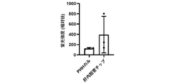
- FIG. 13 is a graph showing the results of measuring the fluorescence intensity of 5(6)-carboxy-2',7'-dichlorofluorescein (CDF) in Experimental Example 3.
- FIG. 14 is a graph showing the results of quantification of albumin in the upper channel and the lower channel by ELISA in Experimental Example 3.
- FIG. 15 is a confocal image of an intrahepatic bile duct chip in Experimental Example 4.
- FIG. 12 is a fluorescence microscope image of bile acid transporter BSEP stained by immunostaining of PHH cultured in an intrahepatic bile duct chip in Experimental Example 3.
- FIG. 13 is a graph showing the results of measuring the fluorescence intensity of 5(6)
- FIG. 16 is an image showing a cross section of an intrahepatic bile duct chip in Experimental Example 4.
- FIG. 17 is a graph showing the quantification results of bile acids in Experimental Example 4.
- FIG. 18 is a fluorescent microscope image of a cross section of the fluidic device in Experimental Example 5.
- FIG. 19 is a graph showing the results of quantitative RT-PCR of liver markers in Experimental Example 6.
- FIG. 20 is a graph showing the results of quantitative RT-PCR of bile duct cell markers in Experimental Example 6.
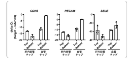
- FIG. 21 is a graph showing the results of quantitative RT-PCR of endothelial markers in Experimental Example 6.
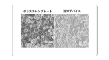
- FIG. 22 is a phase image of PHH cultured on the PET film of the fluidic device and PHH cultured on the polystyrene plate in Experimental Example 6.
- FIG. 22 is a phase image of PHH cultured on the PET film of the fluidic device and PHH cultured on the polystyrene plate in Experimental Example 6.
- FIG. 23 is a fluorescence microscope image showing the results of immunochemical staining in Experimental Example 6.
- FIG. 24 is a graph showing the measurement results of albumin secretion in Experimental Example 6.
- FIG. 25 is a graph showing the quantification results of drugs in Experimental Example 7.
- FIG. 26 is a graph showing the quantification results of drugs in Experimental Example 7.
- FIG. 27 is a graph showing the results of calculating the correlation coefficient R2 value between the drug absorption ratio and the physicochemical properties of the drug in Experimental Example 7.
- FIG. 28 is a graph showing the results of quantitative RT-PCR in Experimental Example 9.
- FIG. 29 is a graph showing the measurement results of drug metabolites in Experimental Example 9.
- FIG. 30 is a graph showing the measurement results of 2-hydroxyatorvastatin (2OH-ATV) in Experimental Example 9.
- FIG. 31 is a graph showing the measurement results of atorvastatin (ATV) in Experimental Example 9.
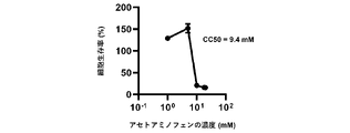
- FIG. 32 is a graph showing the measurement results of cell viability in Experimental Example 10.
- FIG. 33 is a graph showing measurement results of cell viability in Experimental Example 10.
- FIG. 34 is a graph showing the results of quantitative RT-PCR in Experimental Example 10.
- FIG. 35 is a graph showing the results of quantification of TGF- ⁇ 1 by ELISA in Experimental Example 10.
- FIG. 36 is a graph showing the results of quantitative RT-PCR in Experimental Example 10.
- FIG. 37 is a graph showing the results of quantitative RT-PCR in Experimental Example 10.
- Biomimetic systems MMS
- Liver-on-a-chip model liver-chip
- primary human hepatocytes PH
- polydimethylsiloxane PDMS
- PDMS materials fluidic device
- PDMS-based microfluidic device PDMS device
- cytochrome P450 CYP
- polystyrene PS
- PET polyethylene terephthalate
- albumin albumin
- albumin albumin, ALB
- cytokeratin 18, CK18 midazolam
- MDZ diclofenac
- phenacetin PHE
- bufralol BAF
- S-mephenytoin MPHT
- 1-hydroxymidazolam 1-hydroxymidazolam, 1OH-MDZ
- 4-hydroxydiclofenac 4-hydroxydiclofenac
- APAP 1-hydroxybufuralol
- 4- Hydroxymephenytoin 4-hydroxymephenytoin
- the invention provides a biliary tip.
- the bile duct chip of this embodiment includes a membrane capable of mass transfer from one surface to the other surface, a first substrate having a first recess forming a first channel, and a second channel. a second substrate having a second recess, wherein the first substrate, the film, and the second substrate are laminated in this order, and the first recess of the first substrate is The opening faces one surface of the film, the second concave portion of the second substrate has an opening facing the other surface of the film, and the one surface of the film faces the first surface.
- Biliary epithelial cells are arranged on the surface of the inner wall of the first channel to form a tube.
- the bile duct tip of this embodiment has a tubular bile duct-like structure.
- FIG. 1 is a schematic diagram showing the structure of the intrahepatic bile duct in vivo.
- the bile duct chip of this embodiment can imitate, for example, an intrahepatic bile duct in vivo.
- FIG. 2(a) is a plan view (photograph) of the bile duct chip of the present embodiment.
- FIG. 2(b) is a perspective view showing the structure of the bile duct chip of this embodiment.
- FIG.2(c) is the schematic diagram which expanded the part enclosed with the square of FIG.2(b).
- the bile duct chip 200 includes a membrane 210 capable of mass transfer from one side to the other side, and a first substrate 221 having a first recess forming a first channel 220. and a second substrate 231 having a second recess forming the second flow path 230, the first substrate 221, the film 210, and the second substrate 231 being laminated in this order,
- the opening of the first recess of the first substrate 221 faces one surface of the film 210
- the opening of the second recess of the second substrate 231 faces the other surface of the film 210 .
- one side of the membrane 210 forms part of a first flow path 220 and the other side of the membrane 210 forms part of a second flow path 230 and the first flow path 220 and the second channel 230 are in communication via the membrane 210, and bile duct epithelial cells 222 are arranged on the surface of the inner wall of the first channel 220 to form a tube.
- a recess means a portion that is recessed from a reference plane.
- the reference surface is the surface facing the film 210 of the first substrate 221 .
- the first concave portion (groove) formed in the first substrate 221 serves as the wall of the first channel 220 .
- a second concave portion (groove) formed in the second substrate 231 serves as a wall of the second channel 230 .
- the film 210 may be a single-layer film, or may be a laminated film of two or more layers.
- the one surface of the film 210 means the surface facing the opening of the first concave portion of the film closest to the first substrate 221 .
- the other surface of the film 210 means the surface facing the opening of the second concave portion of the film closest to the second substrate 231 .
- the cross-sectional width of the first channel 220 and the second channel 230 may be about 100 ⁇ m to 10 mm, and the height may be about 30 ⁇ m to 3 mm. Also, the lengths of the first channel 220 and the second channel 230 can be appropriately adjusted depending on the purpose, and may be, for example, about 1 mm to 100 mm.
- An inlet and an outlet are preferably provided at the end of the first channel 220 for introducing and discharging cells and culture medium into the channel.
- the ends of the second channel 230 are preferably provided with inlets and outlets for introducing and discharging cells and medium into the channel.
- the bile duct chip before seeding cells may be referred to as a fluid device.
- the first flow path 220 may be referred to as a lower layer flow path
- the second flow path 230 may be referred to as an upper layer flow path.
- an elastomer can be preferably used as the material of the first substrate 221 and the second substrate 231. More specifically, polydimethylsiloxane (PDMS), tetrafluoroethylene-propylene (FEPM) and the like can be mentioned. It is not limited to these. PDMS is easy to mold, has high transparency, and is suitable for cell observation. However, as will be described later in Examples, PDMS is highly hydrophobic and may absorb drugs. In contrast, FEPM can inhibit drug absorption.
- PDMS polydimethylsiloxane
- FEPM tetrafluoroethylene-propylene
- a semipermeable membrane with a pore size of about 0.01 to 80 ⁇ m can be preferably used.
- the material of the membrane 210 is not particularly limited, and examples thereof include polyethylene terephthalate (PET), collagen vitrigel, polycarbonate (PC), and the like.
- PET polyethylene terephthalate
- PC polycarbonate
- the membrane 210 may be a single-layer semipermeable membrane, or may be a semipermeable membrane having two or more layers laminated.
- the second cell 232 may be arranged in the second channel 230 , and the second cell 232 may be adjacent to the bile duct epithelial cell 222 across the membrane 210 .
- the second cells 232 may contain one or more cells selected from the group consisting of liver cells and intestinal cells.
- the duct becomes a model that mimics the intrahepatic bile duct in vivo.
- liver cells hepatocytes (parenchymal cells) are preferred.
- the bile duct chip of this embodiment can be said to be an intrahepatic bile duct chip.
- bile acids produced by hepatocytes 232 in the second channel 230 are collected into tubular structures formed by bile duct epithelial cells 222 in the first channel 220.
- the intrahepatic bile duct chip allows us to observe the directional transport of bile acids. Also, the cholestatic effect of drugs can be evaluated. Cholestasis occurs when bile acids are not properly excreted into the bile ducts and remain in hepatocytes. Intrahepatic bile duct chips can be used to conveniently identify drugs that may cause cholestasis.
- the second cells 232 are enterocytes
- the drug added to the second channel is metabolized by the enterocytes and then transported into the first channel.
- Intestinal epithelial cells are preferred as intestinal cells.
- Liver cells and intestinal cells may be primary cells, established cells, or cells induced to differentiate from pluripotent stem cells.
- Pluripotent stem cells include embryonic stem cells (ESC), induced pluripotent stem cells (iPSC), and the like.
- the present invention is a method of manufacturing a bile duct chip, comprising: a first substrate having a membrane capable of mass transfer from one side to the other side and a first recess forming a first flow path; and a second substrate having a second concave portion forming a second flow path, wherein the first substrate, the film, and the second substrate are laminated in this order, and the The opening of the first recess of the first substrate faces one surface of the film, and the opening of the second recess of the second substrate faces the other surface of the film, One side of the membrane forms part of the first channel, the other side of the membrane forms part of the second channel, and the first channel and the A second flow path comprises seeding the first flow path of the fluidic device communicating through the membrane with biliary epithelial cells and a lumenizing factor in the first flow path. and introducing a culture medium.
- the bile duct chip 200 described above can be manufactured by the manufacturing method of the present embodiment.
- the manufacturing method of this embodiment has a membrane 210 capable of mass transfer from one side to the other side, and a first recess forming a first channel 220.
- a first substrate 221 and a second substrate 231 having a second concave portion forming a second flow path 230 are provided.
- the opening of the first concave portion of the first substrate 221 faces one surface of the film 210
- the opening of the second concave portion of the second substrate 231 faces the film 210 other than the film 210 .
- one side of the membrane 210 forms part of the first channel 220, the other side of the membrane 210 forms part of the second channel 230, and the second The first channel 220 and the second channel 230 are in communication with each other through the membrane 210. Seeding the biliary epithelial cells 222 in the first channel 220 of the fluidic device 200; introducing medium containing the lumenalizing factor into the tract 220.
- the bile duct epithelial cells 222 may be primary cells, established cells, or cells induced to differentiate from pluripotent stem cells.
- Pluripotent stem cells include embryonic stem cells (ESC), induced pluripotent stem cells (iPSC), and the like.
- examples of the lumen-forming factor include any one or more factors selected from the group consisting of Delta Like Canonical Notch Ligand 1 (DLL1) and Delta Like Canonical Notch Ligand 4 (DLL4). be done.
- DLL1 Delta Like Canonical Notch Ligand 1
- DLL4 Delta Like Canonical Notch Ligand 4
- the luminalization factor is DLL1.
- concentration of the lumen-forming factor in the medium is preferably about 1-100 ng/mL, preferably about 10 ng/mL.
- the step of seeding the second cells 232 in the second channel 230 is performed. It may further contain: As a result, the second cells 232 are adjacent to the bile duct epithelial cells 222 across the membrane 210 .
- the second cells 232 may contain any one or more cells selected from the group consisting of liver cells and intestinal cells. Liver cells are the same as described above. When the second cells 232 are liver cells, the ducts are models that mimic the intrahepatic bile ducts in vivo.
- the present invention provides a method for assessing bile acid kinetics, comprising a first membrane having a membrane capable of mass transfer from one side to another side and a first recess forming a first flow path. and a second substrate having a second concave portion forming a second flow path, wherein the first substrate, the film, and the second substrate are laminated in this order, and The opening of the first recess of the first substrate faces one surface of the film, and the opening of the second recess of the second substrate faces the other surface of the film.
- the second flow path communicates through the membrane, bile duct epithelial cells are arranged on the surface of the inner wall of the first flow path to form a tube, and the second flow path A step of adding a test substance to the first channel or the second channel of the bile duct chip in which liver cells are arranged, and bile acid in the first channel or the second channel or measuring the expression level of a gene or protein associated with bile acid dynamics in the bile duct epithelial cells or the liver cells.
- Bile acid dynamics can be evaluated by the method of the present embodiment.
- the method of this embodiment is a method of evaluating bile acid dynamics using an intrahepatic bile duct chip in which liver cells are arranged in the second channel of the bile duct chip 200 described above.
- the method of this embodiment comprises a membrane 210 capable of mass transfer from one side to the other and a first recess having a first recess forming a first channel 220 .
- the opening of the first recess of the first substrate 221 faces one surface of the film 210
- the opening of the second recess of the second substrate 231 faces the other surface of the film 210 .
- the channel 220 and the second channel 230 are in communication via the membrane 210, and bile duct epithelial cells 222 are arranged on the surface of the inner wall of the first channel 220 to form a tube.
- test substance is not particularly limited, and examples include natural compound libraries, synthetic compound libraries, existing drug libraries, metabolite libraries, and the like.
- Genes or proteins related to bile acid dynamics include the BSEP gene, MRP2 gene, NTCP gene, CYP7A1 gene, and proteins encoded by these genes.
- the kinetics of other factors can also be evaluated along with the kinetics of bile acids.
- Other factors include one or more factors selected from the group consisting of in vivo compounds other than bile acids, drugs and pathogens.
- the fluidic device consisted of two layers of channels separated by a semipermeable membrane.
- the channel layer was made of polydimethylsiloxane (PDMS) and manufactured by soft lithography technique.
- PDMS polydimethylsiloxane
- PDMS prepolymer Sylgard 184, Dow Corning
- curing agent 10:1
- An access hole was punched in the PDMS with a 6 mm biopsy punch (Kai) to introduce liquid into the channel.
- the two PDMS layers were each adhered to a semipermeable polyethylene terephthalate (PET) membrane with 3 ⁇ m pores (#353091 Falcon) with a thin layer of liquid PDMS prepolymer as a mortar.
- PET polyethylene terephthalate
- a PDMS prepolymer was spin-coated onto a glass slide (4,000 rpm, 60 seconds). The top and bottom layers were then placed on a glass slide and a thin layer of PDMS prepolymer was transferred to the embossed PDMS surface. As a result, the PDMS thin layer as mortar was placed only on the upper surfaces of the channels (recesses). Subsequently, semipermeable membranes were adhered to the lower layer channel and the upper layer channel, respectively, and then the lower layer and the upper layer were laminated so that the lower layer semipermeable membrane and the upper layer semipermeable membrane were in contact with each other. The combined layers were left at room temperature for 1 day to remove air bubbles and then placed in an oven at 60° C. overnight to cure the PDMS adhesive. As a result, the lower layer and the upper layer were bonded with the two layers of semipermeable membranes sandwiched therebetween, and a fluidic device having channels separated by the semipermeable membranes was obtained.
- the fluidic device was sterilized by placing it under ultraviolet (UV) light for 1 hour prior to cell culture.
- UV ultraviolet
- HuCCT1 cells were suspended at 5 ⁇ 10 5 cells/mL in RPMI containing 10% fetal bovine serum (FBS), 1 ⁇ GlutaMAX, penicillin/streptomycin. 10 ⁇ L of cell suspension was introduced into the fibronectin-coated underlying channel of the fluidic device. One hour after seeding the cells, 200 ⁇ L of medium was added to the upper and lower channels.
- FBS fetal bovine serum
- 1 ⁇ GlutaMAX penicillin/streptomycin
- Human umbilical vein endothelial cells (HUVEC) were suspended at 5 ⁇ 10 6 mL in EGM-2 Endothelial Cell Growth Medium-2 Bullet Kit (Lonza). 10 ⁇ L of cell suspension was introduced into the fibronectin-coated underlying channel of the fluidic device. One hour after seeding the cells, 200 ⁇ L of medium was added to the upper and lower channels.
- HUVEC human hepatocytes
- Vials of PHH were rapidly thawed in a 37° C. shaking water bath.
- the vial contents were then transferred into pre-warmed Cryopreserved Hepatocyte Recovery Medium (Thermo Fisher Scientific) and the suspension was centrifuged at 1,200 rpm for 5 minutes at room temperature.
- PHH was suspended at 5 ⁇ 10 6 cells/mL in HCM (Lonza) containing 10% fetal bovine serum (FBS). 10 ⁇ L of cell suspension was introduced into the type I collagen-coated upper channel of the fluidic device.
- FBS fetal bovine serum
- Quantitative RT-PCR was performed using SYBR Green PCR Master Mix (Thermo Fisher Scientific) and StepOne Plus qPCR system (Thermo Fisher Scientific).
- the 2- ⁇ CT method was used for relative quantification of target mRNA levels.
- the quantitative value of the target gene was normalized by the quantitative value of the housekeeping gene glyceraldehyde-3-phosphate dehydrogenase (GAPDH).
- GPDH housekeeping gene
- the nucleotide sequences of the PCR primers are shown in Table 1 below.
- CDFDA Transport Assay 10 ⁇ M 5(6)-carboxy-2′,7′-dichlorofluorescein diacetate (CDFDA) was added to the upper channel. After 3 hours, the culture supernatant in the lower channel was collected. The fluorescence intensity of 5(6)-carboxy-2',7'-dichlorofluorescein (CDF), a metabolite of CDFDA, in the recovered culture supernatant was measured.
- CDF 5(6)-carboxy-2′,7′-dichlorofluorescein diacetate
- PHH was fixed with 4% paraformaldehyde in phosphate-buffered saline (PBS) for 15 minutes.
- Cells were blocked with PBS containing 10% FBS, 1% bovine serum albumin and 0.2% Triton X-100 for 45 minutes at room temperature before incubation with primary antibody overnight at 4°C followed by 2 Incubate with the following antibody for 1 hour at room temperature.
- the antibodies used are shown in Table 2 below.
- the PiggyBac vector-based EGFP expression vector, pPV-EF1a-EiP-A was transfected with the PiggyBac transposase vector, pHL-EF1a-hcPBase-A, into HuCCT1 cells using Lipofectamine 2000 (Thermo Fisher Scientific). Mr. Ection, selected with puromycin. All of the above vectors were provided by Dr. Akitsu Hotta (Research Institute for iPS Cell Research and Application, Kyoto University).
- LC-MS/MS analysis was performed to measure CYP activity.
- PHHs were incubated in DMEM containing 10 mM HEPES for 30 minutes prior to CYP substrate treatment.
- PHH was subsequently added to 5 ⁇ M MDZ (10H-MDZ metabolite), 50 ⁇ M MPHT (4OH-MPHT metabolite), 5 ⁇ M DIC (4OH-DIC metabolite), 10 ⁇ M BUF (1OH-BUF metabolite) or Cultured in a medium containing 50 ⁇ M PHE (the metabolite is APAP).
- Supernatants were harvested after 1, 2, 4 hours of treatment with substrate. When the supernatant was collected, medium containing an equal volume of substrate was added.
- the recovered supernatant was mixed with an equal volume of acetonitrile (Fujifilm Wako Pure Chemical Industries, Ltd.) containing 5 ⁇ M propranolol (internal standard).
- the sample was filtered through Cosmoice Filter W (Nacalai Tesque) with a pore size of 0.45 ⁇ m, then the supernatant was analyzed by LC-MS/MS, and the concentration of metabolites was measured based on the standard curve.
- LC-MS/MS analysis was performed using LCMS-8040 (Shimadzu Corporation).
- Table 3 shows the ionization mode and multiple-reaction monitoring (MRM) transitions of the mass spectrometer.
- the dwell time for each MRM transition was set at 100 ms.
- PHHs were incubated with dimethylsulfoxide (DMSO) or DMEM containing 100 ⁇ M SKF-525A (Toronto Research Chemicals) and 10 mM HEPES for 30 minutes before adding substrate. Subsequently, PHH was cultured in a medium containing 1 ⁇ M ATV (Fuji Film Wako Pure Chemical Industries). Supernatants were harvested 1, 2, 4 hours after treatment with substrate. When the supernatant was collected, an equal volume of medium containing substrate was added.
- DMSO dimethylsulfoxide
- DMEM DMEM containing 100 ⁇ M SKF-525A (Toronto Research Chemicals) and 10 mM HEPES for 30 minutes before adding substrate. Subsequently, PHH was cultured in a medium containing 1 ⁇ M ATV (Fuji Film Wako Pure Chemical Industries). Supernatants were harvested 1, 2, 4 hours after treatment with substrate. When the supernatant was collected, an equal volume of medium containing substrate was added.
- a fraction (20 ⁇ L) of the collected supernatant was mixed with 20 ⁇ L of milliQ water and 120 ⁇ L of acetonitrile containing 10 nM internal standard (fluvastatin, Fujifilm Wako Pure Chemical Industries). After centrifugation, 100 ⁇ L of supernatant was analyzed by LC-MS/MS. If the analyte was at high concentration, the supernatant was diluted 40-fold with Milli-Q water, if necessary.
- the mass spectrometer was set to MRM mode and operated with an electrospray ionization source. Quantification of ATV was performed in positive ion mode and quantification of 2OH-ATV and fluvastatin was performed in negative ion mode.
- the MRM transitions (m/z of precursor ion/m/z of product ion) were 559.1/440.2 (ATV), 573.1/278.1 (2OH-ATV), and 410.0/348. 0 (fluvastatin).
- collision energies were set at 31 V (ATV), ⁇ 52 V (2OH-ATV), and ⁇ 22 V (fluvastatin).
- LC separation was performed at 40°C using a PC HILIC (2.0 mm i.d. x 150 mm, 3 ⁇ m, Osaka Soda).
- the mobile phase used a mixture of 30% solvent A (0.1% formic acid/20% acetonitrile in 10 mM ammonium acetate) and 70% solvent B (0.1% formic acid/95% acetonitrile in 10 mM ammonium acetate). and sent at a flow rate of 0.4 mL/min.
- Data acquisition and processing were performed using Analyst(R) software version 1.7.1 (AB Sciex LLC).
- CYP induction test PHHs were treated with 50 ⁇ M omeprazole, 500 ⁇ M phenobarbital or 20 ⁇ M rifampicin (all from Fujifilm Wako Pure Chemical) for 48 hours. These drugs are known to induce CYP1A2, 2B6 and 3A4, respectively.
- CYP expression levels were measured by quantitative RT-PCR.
- the expression level of the target gene was normalized by the expression level of GAPDH.
- Inducibility was calculated as fold change in expression levels in DMSO-treated cells.
- the PCR primer sequences are shown in Table 1 above.
- TGF- ⁇ 1 PHHs were treated with 100 ng/mL TGF- ⁇ 1 for 48 hours. To quantify the active TGF- ⁇ 1 in the supernatant, the medium was collected and analyzed using the TGF beta-1 Human ELISA Kit (BMS249-4, Thermo Fisher Scientific) according to the manufacturer's instructions. The amount of activated TGF- ⁇ 1 was calculated based on each standard.
- FIG. 1 is a schematic diagram showing the structure of an intrahepatic bile duct in vivo.
- FIG. 2 is a schematic diagram of an intrahepatic bile duct-on-a-chip (IHBD chip).
- the intrahepatic bile duct chip 200 is composed of two channels and a PET membrane 210 .
- the upper layer channel 230 and the lower layer channel 220 are separated by the membrane 210 .
- HuCCT1 cells 222 which are human cholangiocarcinoma cell lines, are seeded inside the lower channel 220 of the device 200. Seeded inside. As a result of culturing the HuCCT1 cells 222 inside the lower channel 220, the HuCCT1 cells formed a tubular structure.
- FIG. 3 shows cross-sectional fluorescence microscopic images taken 1, 2, 4, and 10 days after the GFP-expressing HuCCT1 cells were cultured inside the lower channel 220 .
- GFP-expressing HuCCT1 cells formed tubular structures.
- FIGS. 4 to 6 are images showing the results of immunochemical staining analysis of intrahepatic bile duct chips.
- HuCCT1 cells were seeded in the lower channel, and 4 days later, PHH was seeded in the upper channel. Subsequently, immunostaining for ALB and CK19 was performed. Nuclei were also stained with DAPI.
- FIG. 4 shows a confocal image
- Figure 5 shows a cross section of an intrahepatic bile duct chip.
- CK19-positive HuCCT1 cells formed a ring structure within the device.
- FIG. 6 is an enlarged image around the membrane of the intrahepatic bile duct tip.
- FIG. 6 shows that a monolayer of ALB-positive hepatocytes is adjacent to bile duct-like structures.
- Fig. 7 is a fluorescence microscope image showing the results of immunostaining of PHH co-cultured with HuCCT1 cells in an intrahepatic bile duct chip (indicated as "chip” in Fig. 7).
- HuCCT1 cells were seeded in the lower channel of the fluidic device.
- PHH was seeded in the upper channel of the same fluidic device.
- immunostaining of ALB in PHH cultured in intrahepatic bile duct chips was performed. Nuclei were also stained with DAPI.
- liver markers ALB, AAT, CYP3A4 and CYP2B6
- BSEP bile acid-related genes
- FIG. 8 is a graph showing the results of quantitative RT-PCR.
- “mono” indicates the result when only PHH was cultured without seeding HuCCT1 cells in the fluidic device.
- chip indicates the results when HuCCT1 cells and PHH were co-cultured for 7 days in a fluidic device.
- the vertical axis indicates the relative value of the expression level with the expression level in the case of "mono” set to 1.
- “*” indicates a significant difference at p ⁇ 0.05
- a sample treated with dimethyl sulfoxide (DMSO) instead of CDCA was also prepared.
- DMSO dimethyl sulfoxide
- FIG. 9 is a graph showing the results of quantitative RT-PCR.
- the vertical axis indicates the relative value of the expression level with the expression level when treated with DMSO set to 1.
- Intrahepatic bile duct tip was used to study bile acid flow.
- a model blood vessel chip in which PHH and human umbilical vein endothelial cells (HUVEC) were co-cultured in a fluidic device was also produced.
- HuCCT1 cells or HUVECs were seeded into the underlying channel of the fluidic device.
- 4 days after seeding the cells PHH was seeded in the upper channel of the fluidic device.
- FIG. 10 is a graph showing the quantification results of bile acids.
- “only PHH” indicates the result when only PHH was cultured without seeding HuCCT1 cells in the fluidic device.
- “Bile duct cells only” indicates the results when only HuCCT1 cells were cultured in the fluidic device and PHH was not seeded.
- the “intrahepatic bile duct chip” indicates the result of co-culturing HuCCT1 cells and PHH in the fluidic device.
- “*” indicates significant difference at p ⁇ 0.05.
- FIG. 11 is a graph showing the quantification results of bile acids.
- PHH was cultured without seeding HuCCT1 cells in the fluidic device.
- intrahepatic bile duct chip indicates the result of co-culturing HuCCT1 cells and PHH in a fluidic device.
- ** indicates that there is a significant difference at p ⁇ 0.01.
- Bile acids are known to be excreted into the bile canaliculi via the hepatic transporter BSEP. In order to investigate the reason why the bile acids were transported directionally into the underlying channels, the localization of BSEP was confirmed by immunostaining.
- Fig. 12 is a fluorescence microscope image of BSEP, a bile acid transporter, stained by immunostaining of PHH cultured in an intrahepatic bile duct chip. Nuclei were stained with DAPI.
- “mono” indicates the result when only PHH was cultured without seeding HuCCT1 cells in the fluidic device
- IHBD chip indicates co-culturing of HuCCT1 cells and PHH in the fluidic device for 7 days. indicates that the result is Arrowheads in FIG. 12 indicate the localization of BSEP.
- the expression level of BSEP in the middle of the hepatocyte layer was higher in the PHH-only chip than in the intrahepatic bile duct chip.
- BSEP expression levels were higher in intrahepatic bile duct chips than in PHH-only chips. This result suggests that the localization of BSEP contributes to the directional transport of bile acids to underlying channels.
- CDFDA 5(6)-carboxy-2',7'-dichlorofluorescein diacetate
- FIG. 13 is a graph showing the measurement results of fluorescence intensity.
- “only PHH” indicates the result when only PHH was cultured without seeding HuCCT1 cells in the fluidic device.
- intrahepatic bile duct chip indicates the result of co-culturing HuCCT1 cells and PHH in a fluidic device.
- “*" indicates that there is a significant difference at p ⁇ 0.05.
- albumin in the medium was quantified.
- albumin is produced in hepatocytes and secreted into plasma.
- GFP-expressing HuCCT1 cells or GFP-expressing HUVECs were seeded in the lower channel, and after 4 days, PHH was seeded in the upper channel. Subsequently, one day later, albumin secretion in the intrahepatic bile duct tip or vascular tip was measured by ELISA.
- Fig. 14 is a graph showing the results of quantification of albumin in the upper channel (Top) and lower channel (Bottom) by ELISA 1 day or 7 days after the start of co-culture.
- albumin was directionally transported to the channels in the lower layer of the vascular chip. However, albumin was not transported to the underlying channels of the intrahepatic bile duct tip.
- Intrahepatic bile duct chips containing hepatocyte-like cells derived from human iPS cells were prepared. GFP-expressing HuCCT1 cells were seeded in the lower channel, and 4 days later, human iPS cell-derived hepatocyte-like cells were seeded in the upper channel. Subsequently, the expression of cytokeratin 18 (CK18), a liver marker, in intrahepatic bile duct chips was analyzed by immunochemical staining.
- CK18 cytokeratin 18
- FIG. 15 is a confocal image
- FIG. 16 is an image showing a cross section of an intrahepatic bile duct chip.
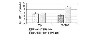
- FIG. 17 is a graph showing the quantification results of bile acids. As a result, it was confirmed that intrahepatic bile duct chips containing hepatocyte-like cells derived from human iPS cells could reproduce bile acid dynamics.
- FIG. 18 is a cross-sectional fluorescence microscope image of each fluidic device.
- arrows indicate regions where GFP-expressing HuCCT1 cells are not present, and "Control" indicates results in the absence of DLL1 and DLL4.
- liver markers AB, AAT, CYP3A4, CYP7A1, BSEP, MRP2
- AQP, KRT19 bile duct cell markers
- CDH5, PECAM, SELE endothelial markers
- FIG. 19 is a graph showing the results of quantitative RT-PCR of liver markers.
- FIG. 20 is a graph showing the results of quantitative RT-PCR of cholangiocyte markers.
- FIG. 21 is a graph showing the results of quantitative RT-PCR of endothelial markers.
- “Top” indicates the results of cells in the upper channel, and "Bottom” indicates the results of cells in the lower channel.
- FIG. 22 shows phase images of PHH cultured on the PET membrane of the fluidic device and PHH cultured on the polystyrene plate.
- FIG. 23 is a fluorescence microscope image showing the results of immunochemical staining. As a result, strong expression of ALB and CK18 by PHH was observed under any conditions.
- FIG. 24 is a graph showing the measurement results of albumin secretion.
- “top” indicates the result of the flow path in the upper layer of the fluidic device
- “bottom” indicates the result of the flow path in the lower layer of the fluidic device.
- the amount of human albumin secreted into the medium collected from the upper channel of the fluidic device was about the same as the amount of human albumin secreted into the medium collected from the polystyrene plate.
- the estimated diameter of human albumin (approximately 6 nm) is smaller than the pore size of the PET membrane (3 ⁇ m)
- no human albumin was detected from the lower channel of the fluidic device.
- FIG. 25 is a graph showing the quantitative results of each drug.
- CYP activity is defined by the rate of metabolite formation
- drug metabolites (1-hydroxymidazolam (1OH-MDZ), 4-hydroxydiclofenac (4OH-DIC), acetaminophen (APAP), 1-hydroxy Absorption of bufuralol (1OH-BUF) and 4-hydroxymephenytoin (4OH-MPHT) was also evaluated.
- a medium containing APAP (CYP1A2 metabolite), 1OH-MDZ (CYP3A4 metabolite), 4OH-DIC (CYP2C9 metabolite), 4OH-MPHT (CYP2C19 metabolite) or 1OH-BUF (CYP2D6 metabolite) is transferred to a fluidic device or Added to polystyrene plates. Subsequently, the amounts of these drugs were quantified by LC-MS/MS at 1, 2 and 4 hours after drug addition.
- FIG. 26 is a graph showing the quantitative results of each drug.
- the CYP3A4 substrate MDZ and the CYP2D6 substrate BUF were absorbed into the fluidic device.
- the concentrations of MDZ and BUF decreased to 9.5% and 30% of the initial concentration, respectively, 1 hour after injection into the fluidic device.
- the MDZ metabolite (1OH-MDZ) was also absorbed into the PDMS device, but the BUF metabolite (1OH-BUF) was not.
- the concentrations of MDZ, BUF and 1OH-MDZ remained constant during the observation period (1-4 hours).
- MedChem Designer 5.5 was used to calculate the diffusion coefficient (DiffCoef), partition coefficient (MLogP, S+LogP and S+logD), molecular weight (MWt) and topological polar surface area (tPSA) of each drug. The results are shown in Table 7 below.
- FIG. 28 is a graph showing the results of quantitative RT-PCR.
- the vertical axis of the graph indicates the fold change with the gene expression level of PHH treated with DMSO set to 1.
- “**” indicates significant difference at p ⁇ 0.01.
- FIG. 29 is a graph showing the measurement results of each metabolite.
- "*” indicates a significant difference at p ⁇ 0.05
- "**” indicates a significant difference at p ⁇ 0.01.
- APAP CYP1A2 metabolite
- 1OH-MDZ CYP3A4 metabolite
- 1OH-BUF CYP2D6 metabolite
- ATV atorvastatin
- PHH was seeded on the fluidic device and polystyrene plate and cultured for 24 hours. Subsequently, PHH was cultured in medium containing ATV for 1, 2 and 4 hours, and the concentrations of 2-hydroxyatorvastatin (2OH-ATV) and ATV were measured by LC-MS/MS. For comparison, a sample in which the pan-CYP inhibitor SKF-525A was added to the medium was also prepared.
- FIG. 30 is a graph showing the measurement results of 2OH-ATV.
- "**" indicates that there is a significant difference at p ⁇ 0.01.
- PHH cultured in the fluidic device maintained the activities of CYP3A4, CYP1A2 and CYP2D6, but for unknown reasons, the activities of CYP2C9 and CYP2C19 were significantly reduced.
- CYP3A activity was maintained in PHH cultured in the fluidic device, but the formation rate of 2OH-ATV was partially reduced. This result suggests that the transport activity of OATP1B may be reduced in fluidic devices, considering that the rate-limiting step in hepatic clearance of ATV is the hepatic uptake process.
- the cell viability of PHH cultured in a fluidic device was significantly lower than that of PHH cultured in a polystyrene plate. This result indicates that the fluidic device has higher sensitivity to APAP-induced liver injury.
- CDCA chenodeoxycholic acid
- GW4046 the synthetic ligand
- FIG. 34 is a graph showing the results of quantitative RT-PCR.
- "**" indicates that there is a significant difference at p ⁇ 0.01.
- the gene expression level of BSEP a bile acid excretion transporter
- the gene expression level of CYP7A1 the rate-limiting enzyme for hepatic bile acid synthesis, decreased only in the fluidic device.
- TGF- ⁇ 1 transforming growth factor- ⁇ 1
- FIG. 35 is a graph showing the results of ELISA.
- “top” indicates the result of the upper channel
- “bottom” indicates the result of the lower channel.
- groups that do not share the same letter are significantly different from each other (p ⁇ 0.05). The results showed that the fluidic device did not adsorb TGF- ⁇ 1. On the other hand, polystyrene plates adsorbed TGF- ⁇ 1.
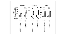
- fibrosis markers ACTA2, COL1A1 and TIMP1 were measured by quantitative RT-PCR.
- FIG. 36 is a graph showing the results of quantitative RT-PCR.
- the vertical axis indicates relative values, with the gene expression level in cells (control) treated with phosphate-buffered saline (PBS) being 1.
- PBS phosphate-buffered saline
- TGFBR2 TGF- ⁇ type II receptor
- FIG. 37 is a graph showing the results of quantitative RT-PCR.
- the vertical axis indicates the relative value with the PHH gene expression level immediately after thawing as 1.
- both fluidic devices and polystyrene plates can be used to assess fibrosis caused by TGF- ⁇ 1. From the above results, it was confirmed that both PHH cultured in the fluidic device and PHH cultured in the polystyrene plate retained the ability to respond to drugs and recombinant proteins.
- a bile duct tip having a tubular bile duct-like structure can be provided.
- bile duct chip 210... membrane, 220, 230... channel, 221, 231... substrate, 222... bile duct epithelial cell, 232... second cell.
Landscapes
- Health & Medical Sciences (AREA)
- Chemical & Material Sciences (AREA)
- Life Sciences & Earth Sciences (AREA)
- Engineering & Computer Science (AREA)
- Bioinformatics & Cheminformatics (AREA)
- Organic Chemistry (AREA)
- Wood Science & Technology (AREA)
- Zoology (AREA)
- Biomedical Technology (AREA)
- Genetics & Genomics (AREA)
- Biotechnology (AREA)
- Sustainable Development (AREA)
- Biochemistry (AREA)
- General Engineering & Computer Science (AREA)
- General Health & Medical Sciences (AREA)
- Microbiology (AREA)
- Dispersion Chemistry (AREA)
- Clinical Laboratory Science (AREA)
- Molecular Biology (AREA)
- Medicinal Chemistry (AREA)
- Apparatus Associated With Microorganisms And Enzymes (AREA)
Priority Applications (2)
| Application Number | Priority Date | Filing Date | Title |
|---|---|---|---|
| JP2023505595A JPWO2022191222A1 (https=) | 2021-03-10 | 2022-03-09 | |
| US18/280,659 US20240150691A1 (en) | 2021-03-10 | 2022-03-09 | Bile duct chip and use thereof |
Applications Claiming Priority (2)
| Application Number | Priority Date | Filing Date | Title |
|---|---|---|---|
| US202163158891P | 2021-03-10 | 2021-03-10 | |
| US63/158,891 | 2021-03-10 |
Publications (1)
| Publication Number | Publication Date |
|---|---|
| WO2022191222A1 true WO2022191222A1 (ja) | 2022-09-15 |
Family
ID=83226850
Family Applications (1)
| Application Number | Title | Priority Date | Filing Date |
|---|---|---|---|
| PCT/JP2022/010191 Ceased WO2022191222A1 (ja) | 2021-03-10 | 2022-03-09 | 胆管チップ及びその使用 |
Country Status (3)
| Country | Link |
|---|---|
| US (1) | US20240150691A1 (https=) |
| JP (1) | JPWO2022191222A1 (https=) |
| WO (1) | WO2022191222A1 (https=) |
Citations (4)
| Publication number | Priority date | Publication date | Assignee | Title |
|---|---|---|---|---|
| JP2011528232A (ja) * | 2008-07-16 | 2011-11-17 | チルドレンズ メディカル センター コーポレーション | マイクロチャネルを有する臓器模倣装置ならびにその使用および製造方法 |
| WO2013086502A1 (en) * | 2011-12-09 | 2013-06-13 | President And Fellows Of Harvard College | Organ chips and uses thereof |
| WO2016158417A1 (ja) * | 2015-03-27 | 2016-10-06 | 国立研究開発法人農業生物資源研究所 | 肝代謝物の毛細胆管様構造への蓄積と排泄を促進する肝細胞培養装置、並びに該肝細胞培養装置を用いた胆汁中又は血液中排泄感受性の候補化合物及び該候補化合物の肝代謝物の評価方法 |
| CN106754636A (zh) * | 2015-11-19 | 2017-05-31 | 中国人民解放军第二军医大学 | 体外诱导原代肝细胞胆管化并长期培养、扩增和分化的方法及其应用 |
Family Cites Families (2)
| Publication number | Priority date | Publication date | Assignee | Title |
|---|---|---|---|---|
| SG11201804700VA (en) * | 2015-12-04 | 2018-07-30 | Emulate Inc | Devices and methods for simulating a function of a liver tissue |
| WO2019033096A1 (en) * | 2017-08-11 | 2019-02-14 | The Trustees Of The University Of Pennsylvania | MEMBRANE INSERTS DERIVED FROM NATIVE EXTRACELLULAR MATRIX FOR CHIP ORGANS, MULTILAYER MICROFLUIDIC MICRODISPOSITIVES, AND THREE DIMENSIONAL CELL CULTURE SYSTEMS |
-
2022
- 2022-03-09 WO PCT/JP2022/010191 patent/WO2022191222A1/ja not_active Ceased
- 2022-03-09 JP JP2023505595A patent/JPWO2022191222A1/ja active Pending
- 2022-03-09 US US18/280,659 patent/US20240150691A1/en active Pending
Patent Citations (4)
| Publication number | Priority date | Publication date | Assignee | Title |
|---|---|---|---|---|
| JP2011528232A (ja) * | 2008-07-16 | 2011-11-17 | チルドレンズ メディカル センター コーポレーション | マイクロチャネルを有する臓器模倣装置ならびにその使用および製造方法 |
| WO2013086502A1 (en) * | 2011-12-09 | 2013-06-13 | President And Fellows Of Harvard College | Organ chips and uses thereof |
| WO2016158417A1 (ja) * | 2015-03-27 | 2016-10-06 | 国立研究開発法人農業生物資源研究所 | 肝代謝物の毛細胆管様構造への蓄積と排泄を促進する肝細胞培養装置、並びに該肝細胞培養装置を用いた胆汁中又は血液中排泄感受性の候補化合物及び該候補化合物の肝代謝物の評価方法 |
| CN106754636A (zh) * | 2015-11-19 | 2017-05-31 | 中国人民解放军第二军医大学 | 体外诱导原代肝细胞胆管化并长期培养、扩增和分化的方法及其应用 |
Non-Patent Citations (3)
| Title |
|---|
| DONGEUN HUH, BENJAMIN D. MATTHEWS, AKIKO MAMMOTO, MARTÍN MONTOYA-ZAVALA, HONG YUAN HSIN AND DONALD E. INGBER: "Reconstituting Organ-Level Lung Functions on a Chip", SCIENCE, AMERICAN ASSOCIATION FOR THE ADVANCEMENT OF SCIENCE, US, vol. 328, 25 June 2010 (2010-06-25), US , pages 1662 - 1668, XP002678090, ISSN: 0036-8075, DOI: 10.1126/SCIENCE.1188302 * |
| TAKAYAMA, KAZUO: "SY-10-2: Optimization of device materials and cells for the development of liver-on-a-chip with liver function", THE 20TH CONGRESS OF JAPANESE SOCIETY FOR REGENERATIVE MEDICINE; MARCH 11-13, 2021, JAPANESE SOCIETY FOR REGENERATIVE MEDICINE, JP, vol. 20, 8 March 2021 (2021-03-08) - 13 March 2021 (2021-03-13), JP, pages 675, XP009541202 * |
| YU DU; GAURI KHANDEKAR; JESSICA LLEWELLYN; WILLIAM POLACHECK; CHRISTOPHER S. CHEN; REBECCA G. WELLS: "A Bile Duct‐on‐a‐Chip With Organ‐Level Functions", HEPATOLOGY, JOHN WILEY & SONS, INC., US, vol. 71, no. 4, 28 October 2019 (2019-10-28), US , pages 1350 - 1363, XP071566284, ISSN: 0270-9139, DOI: 10.1002/hep.30918 * |
Also Published As
| Publication number | Publication date |
|---|---|
| US20240150691A1 (en) | 2024-05-09 |
| JPWO2022191222A1 (https=) | 2022-09-15 |
Similar Documents
| Publication | Publication Date | Title |
|---|---|---|
| US20230159899A1 (en) | Devices and methods for simulating a function of liver tissue | |
| Choucha‐Snouber et al. | Investigation of ifosfamide nephrotoxicity induced in a liver–kidney co‐culture biochip | |
| US11366103B2 (en) | Multi-well micropatterning by ablation | |
| Schimek et al. | Human multi-organ chip co-culture of bronchial lung culture and liver spheroids for substance exposure studies | |
| Vormann et al. | Implementation of a human renal proximal tubule on a chip for nephrotoxicity and drug interaction studies | |
| Rose et al. | Generation of proliferating human adult hepatocytes using optimized 3D culture conditions | |
| Jang et al. | Reproducing human and cross-species drug toxicities using a Liver-Chip | |
| Theobald et al. | Liver-kidney-on-chip to study toxicity of drug metabolites | |
| Hegde et al. | Dynamic interplay of flow and collagen stabilizes primary hepatocytes culture in a microfluidic platform | |
| Berger et al. | Enhancing the functional maturity of induced pluripotent stem cell–derived human hepatocytes by controlled presentation of cell–cell interactions in vitro | |
| Khetani et al. | Microengineered liver tissues for drug testing | |
| AU2016362491B2 (en) | Devices for simulating a function of a liver tissue and methods of use and manufacturing thereof | |
| Legendre et al. | Metabolic characterization of primary rat hepatocytes cultivated in parallel microfluidic biochips | |
| Rose et al. | DMSO-free highly differentiated HepaRG spheroids for chronic toxicity, liver functions and genotoxicity studies | |
| Al-Hilal et al. | Pulmonary-arterial-hypertension (PAH)-on-a-chip: fabrication, validation and application | |
| US20200224136A1 (en) | Intestine-chip: differential gene expression model | |
| He et al. | Origami-based self-folding of co-cultured NIH/3T3 and HepG2 cells into 3D microstructures | |
| Speer et al. | Evaluation of human primary intestinal monolayers for drug metabolizing capabilities | |
| Kakni et al. | PSC-derived intestinal organoids with apical-out orientation as a tool to study nutrient uptake, drug absorption and metabolism | |
| Nishikawa et al. | Accurate evaluation of hepatocyte metabolisms on a noble oxygen-permeable material with low sorption characteristics | |
| Ma et al. | Efficient proximal tubule-on-chip model from hiPSC-derived kidney organoids for functional analysis of renal transporters | |
| Arakawa et al. | Induction of open-form bile canaliculus formation by hepatocytes for evaluation of biliary drug excretion | |
| Tanaka et al. | Robust and reproducible human intestinal organoid-derived monolayer model for analyzing drug absorption | |
| WO2022191222A1 (ja) | 胆管チップ及びその使用 | |
| Wu et al. | Porcine hepatocytes culture on biofunctionalized 3D inverted colloidal crystal scaffolds as an in vitro model for predicting drug hepatotoxicity |
Legal Events
| Date | Code | Title | Description |
|---|---|---|---|
| 121 | Ep: the epo has been informed by wipo that ep was designated in this application |
Ref document number: 22767176 Country of ref document: EP Kind code of ref document: A1 |
|
| WWE | Wipo information: entry into national phase |
Ref document number: 2023505595 Country of ref document: JP |
|
| WWE | Wipo information: entry into national phase |
Ref document number: 18280659 Country of ref document: US |
|
| NENP | Non-entry into the national phase |
Ref country code: DE |
|
| 122 | Ep: pct application non-entry in european phase |
Ref document number: 22767176 Country of ref document: EP Kind code of ref document: A1 |