WO2022190606A1 - 紫外線殺菌装置、紫外線殺菌装置の作動方法、紫外線殺菌装置の作動プログラム - Google Patents
紫外線殺菌装置、紫外線殺菌装置の作動方法、紫外線殺菌装置の作動プログラム Download PDFInfo
- Publication number
- WO2022190606A1 WO2022190606A1 PCT/JP2022/000257 JP2022000257W WO2022190606A1 WO 2022190606 A1 WO2022190606 A1 WO 2022190606A1 JP 2022000257 W JP2022000257 W JP 2022000257W WO 2022190606 A1 WO2022190606 A1 WO 2022190606A1
- Authority
- WO
- WIPO (PCT)
- Prior art keywords
- ultraviolet
- person
- ultraviolet light
- human sensor
- irradiation
- Prior art date
- Legal status (The legal status is an assumption and is not a legal conclusion. Google has not performed a legal analysis and makes no representation as to the accuracy of the status listed.)
- Ceased
Links
Images








Classifications
-
- A—HUMAN NECESSITIES
- A61—MEDICAL OR VETERINARY SCIENCE; HYGIENE
- A61L—METHODS OR APPARATUS FOR STERILISING MATERIALS OR OBJECTS IN GENERAL; DISINFECTION, STERILISATION OR DEODORISATION OF AIR; CHEMICAL ASPECTS OF BANDAGES, DRESSINGS, ABSORBENT PADS OR SURGICAL ARTICLES; MATERIALS FOR BANDAGES, DRESSINGS, ABSORBENT PADS OR SURGICAL ARTICLES
- A61L2/00—Disinfection or sterilisation of materials or objects, in general; Accessories therefor
- A61L2/02—Disinfection or sterilisation of materials or objects, in general; Accessories therefor using physical processes
- A61L2/08—Radiation
- A61L2/10—Ultraviolet [UV] radiation
-
- A—HUMAN NECESSITIES
- A61—MEDICAL OR VETERINARY SCIENCE; HYGIENE
- A61L—METHODS OR APPARATUS FOR STERILISING MATERIALS OR OBJECTS IN GENERAL; DISINFECTION, STERILISATION OR DEODORISATION OF AIR; CHEMICAL ASPECTS OF BANDAGES, DRESSINGS, ABSORBENT PADS OR SURGICAL ARTICLES; MATERIALS FOR BANDAGES, DRESSINGS, ABSORBENT PADS OR SURGICAL ARTICLES
- A61L2/00—Disinfection or sterilisation of materials or objects, in general; Accessories therefor
- A61L2/24—Apparatus using programmed or automatic operation
Definitions
- the technology of the present disclosure relates to an ultraviolet sterilizer, an ultraviolet sterilizer operating method, and an ultraviolet sterilizer operating program.
- sterilization technology With the spread of the new coronavirus (SARS (Severe Acute Respiratory Syndrome)-CoV (Coronavirus)-2), sterilization technology is attracting attention. In addition, sterilization means inactivation of bacteria and/or viruses.
- SARS severe Acute Respiratory Syndrome
- Coronavirus Coronavirus-2
- Typical sterilization techniques include alcohol sterilization and ultraviolet sterilization.
- alcohol sterilization has problems such as that alcohol is not suitable for some people.
- Ultraviolet sterilization has conventionally been avoided for use on humans due to concerns about the effects of ultraviolet radiation on humans.
- the present inventors are studying an ultraviolet sterilization device that irradiates at least a part of a person, such as a finger, with ultraviolet rays that have little effect on humans to sterilize them.
- an ultraviolet sterilization apparatus there is a problem from a hygienic point of view in that the ultraviolet ray is emitted by touching an operation member such as a button.
- An embodiment according to the technology of the present disclosure provides an ultraviolet sterilizer capable of hygienically sterilizing people with ultraviolet light, a method of operating the ultraviolet sterilizer, and an operation program for the ultraviolet sterilizer.
- the ultraviolet sterilizer of the present disclosure includes an ultraviolet ray source that emits ultraviolet rays, a human sensor that detects a person without contact, and a control unit.
- the source is exposed to UV light.
- the human sensor does not detect a person, it is preferable not to irradiate the ultraviolet light from the ultraviolet light source.
- control unit causes the ultraviolet light source to stop irradiating ultraviolet light when the human sensor stops sensing a person while the ultraviolet light source is irradiating ultraviolet light.
- control unit causes the ultraviolet source to stop irradiating ultraviolet rays after a preset irradiation time has elapsed after the ultraviolet ray source starts irradiating ultraviolet rays.
- the irradiation time is preferably changed according to at least one of the distance between the site to be sterilized, which is at least a part of the person, and the ultraviolet light source, and the type of bacteria and/or viruses to be sterilized.
- the human sensor senses that the part to be sterilized, which is at least a part of the person, is located in a position facing the ultraviolet emitting part.
- the control unit is a processor, and preferably has a memory connected to or built into the processor.
- the processor acquires identification information for identifying a person, and stores in the storage unit the cumulative irradiation light amount of ultraviolet rays for each person identified by the identification information.
- the central wavelength of ultraviolet rays is 200 nm or more and 230 nm or less.
- a method of operating an ultraviolet sterilizer is a method of operating an ultraviolet sterilizer provided with an ultraviolet ray source that irradiates ultraviolet rays, wherein the human sensor senses a person without contact, and the human sensor senses the person. If so, causing the ultraviolet light source to irradiate the ultraviolet light.
- An operation program for an ultraviolet sterilizer of the present disclosure is an operation program for an ultraviolet sterilizer provided with an ultraviolet ray source for irradiating ultraviolet rays, wherein the human sensor senses a person without contact, and the human sensor senses the person. If so, it causes the computer to perform a process including causing an ultraviolet light source to irradiate the ultraviolet light.
- an ultraviolet sterilizer capable of hygienically sterilizing people with ultraviolet light, a method of operating the ultraviolet sterilizer, and an operation program for the ultraviolet sterilizer.
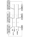
- FIG. 4 is an operation timing chart of a human sensor and an ultraviolet light source; It is a flow chart which shows a processing procedure of an ultraviolet sterilizer.
- FIG. 11 is an operation timing chart of the human sensor and ultraviolet light source of the 2_1 embodiment;
- FIG. 4 is a diagram showing how a distance sensor is used to measure the distance between a finger and an ultraviolet light source;
- FIG. 10 is a diagram showing that the irradiation time is changed according to the distance between the finger and the ultraviolet light source; It is a figure which shows target irradiation light amount information. It is a figure which shows the selection screen displayed on the touch-panel display.
- FIG. 10 is a diagram showing that the irradiation time is changed according to the type of bacteria and/or viruses to be sterilized, in addition to the distance between the finger and the ultraviolet light source. It is a figure which shows a mode that a user holds a connection part by hand and uses an ultraviolet sterilization apparatus.
- 14 is a flow chart showing a processing procedure of the ultraviolet sterilization device shown in FIG. 13; FIG. 14 is a block diagram showing the internal configuration of the ultraviolet sterilizer of the 4_1st embodiment; FIG.
- FIG. 22 is a diagram illustrating an outline of processing of the 4_1 embodiment; It is a figure which shows irradiation prohibition conditions.
- FIG. 10 is a diagram showing a state in which the cumulative amount of irradiated light exceeds the threshold of the irradiation prohibition condition, and the irradiation of ultraviolet rays UV is prohibited.
- FIG. 22 is a diagram showing an overview of the processing of the 4_2 embodiment;
- the ultraviolet sterilizer 2 includes a radiation source section 10 , a connection section 11 and a power supply section 12 .
- the radiation source section 10 and the power supply section 12 are rectangular parallelepipeds of approximately the same size, are connected by a connecting section 11 , and face each other with the connecting section 11 interposed therebetween.
- the back surfaces of the radiation source unit 10, the connecting unit 11, and the power supply unit 12 are flush with each other.
- the radiation source section 10 and the power supply section 12 have the same thickness, and the connection section 11 is thinner than the radiation source section 10 and the power supply section 12 . For this reason, the ultraviolet sterilizer 2 has a shape like a telephone receiver as a whole.
- connection part 11 also serves as a grip for the user to hold the ultraviolet sterilizer 2 with one hand.
- the power supply unit 12 also serves as a pedestal for installing the ultraviolet sterilizer 2 on a horizontal surface 35 (see FIG. 4).
- the radiation source section 10 incorporates an ultraviolet light source 13 and a human sensor 14 .
- the ultraviolet light source 13 emits sterilizing ultraviolet light UV (see FIG. 3, etc.).
- a general ultraviolet lamp using a quartz tube such as an excimer lamp, an LED (Light Emitting Diode), an LD (Laser Diode), or the like can be adopted.
- the human sensor 14 senses a person in a non-contact manner using infrared radiation from the finger 36 (see FIG. 4), reflection of ultrasonic waves, reflection of light (infrared light or visible light), or the like.
- the sensor window 16 is arranged directly below the exit window 15 .
- the exit window 15 is an example of the “exit part” according to the technology of the present disclosure.
- a battery 17 is built into the power supply unit 12 .
- a battery 17 stores power for operating the ultraviolet sterilizer 2 .
- the battery 17 is a secondary battery that can be used repeatedly by charging.
- the power supply unit 12 is heavier than the radiation source unit 10 due to the built-in battery 17 . This increases the sense of stability when the ultraviolet sterilizer 2 is installed on the horizontal surface 35 with the power supply unit 12 facing downward (see FIG. 4). However, since the radiation source section 10 incorporates the ultraviolet light source 13 and the human sensor 14 as described above, the radiation source section 10 is not significantly lighter than the power supply section 12 . Therefore, the radiation source unit 10 and the power supply unit 12 are appropriately counterbalanced.
- a power button 18 is provided on the front surface of the power supply unit 12 . By pressing the power button 18, the power of the ultraviolet sterilizer 2 is turned on and off.
- the power button 18 incorporates an indicator such as an LED that lights when the power is turned on and turns off when the power is turned off.
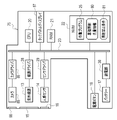
- the ultraviolet sterilizer 2 has a CPU (Central Processing Unit) 20, a RAM (Random Access Memory) 21, and an NVM (Non-Volatile Memory) 22. These CPU 20 , RAM 21 and NVM 22 are interconnected via a bus line 23 .
- the RAM 21 is a work memory for the CPU 20 to execute processing, and is an example of a "memory" according to the technology of the present disclosure.
- the NVM 22 is a storage device such as flash memory, and stores an operation program 25 .
- the operation program 25 is an example of an "ultraviolet sterilizer operation program" according to the technology of the present disclosure. Note that the RAM 21 may be built in the CPU 20 .
- the CPU 20 loads the operation program 25 into the RAM 21 and executes processing according to the operation program 25. Thereby, the CPU 20 comprehensively controls each part of the ultraviolet sterilization device 2 .
- the CPU 20 is an example of a “controller” and a “processor” according to the technology of the present disclosure.
- a line source driver 28 , a sensor driver 29 and a power supply section 30 are connected to the bus line 23 .
- a radiation source driver 28 operates the ultraviolet light source 13 under the control of the CPU 20 .
- the sensor driver 29 operates the human sensor 14 under the control of the CPU 20 .
- the power supply unit 30 supplies electric power from the battery 17 to each unit of the ultraviolet sterilizer 2 .
- a power button 18 is also connected to the bus line 23 .
- the power button 18 emits a power-on signal or a power-off signal when pressed.
- a power-on signal or power-off signal is input to the CPU 20 through the bus line 23 .
- the CPU 20 performs power-on processing according to the power-on signal and power-off processing according to the power-off signal.
- the power-on process is a process for causing the power supply unit 30 to start supplying power to each unit.
- the power-on process is a process of activating the human sensor 14 through the sensor driver 29 .
- the power-off process is a process of causing the power supply unit 30 to stop supplying power to each unit. As a result of this power-off processing, the operation of the human sensor 14 is naturally stopped. That is, the power button 18 is an example of the "operation member" according to the technology of the present disclosure.
- the ultraviolet light source 13 irradiates ultraviolet light with a center wavelength of 200 nm or more and 230 nm or less, which is known to have a bactericidal action and relatively little effect on humans.
- the center wavelength is specifically 207 nm or 222 nm.
- the irradiation intensity K (see FIG. 9, etc.) of the ultraviolet rays UV is constant.
- the irradiation intensity K is a physical quantity representing the radiant energy of ultraviolet rays UV radiated from the ultraviolet light source 13 in a certain direction per unit time, and its unit is mJ/sec.
- the ultraviolet light source 13 radially emits ultraviolet light UV. Therefore, the irradiation area of the ultraviolet rays UV on the surface directly facing the exit window 15 is substantially circular.
- FIG. 4 shows a state in which the ultraviolet sterilizer 2 is installed on a horizontal surface 35 and used.
- the human sensor 14 senses that a human finger 36 is positioned facing the exit window 15 .
- the position facing the exit window 15 is a position within a preset distance range from the exit window 15 .
- the distance range is, for example, a conical range having a height of about 30 to 50 cm, with the center of the sensor window 16 as the apex and the UV irradiation range as the bottom.
- the CPU 20 causes the ultraviolet light source 13 to irradiate the ultraviolet light UV through the radiation source driver .
- the finger 36 is an example of "a part to be sterilized that is at least part of a person" according to the technology of the present disclosure.
- the CPU 20 when the human sensor 14 does not sense that the finger 36 is positioned facing the exit window 15, the CPU 20 does not instruct the ultraviolet light source 13 to irradiate the ultraviolet light UV, or A signal is output to the ultraviolet light source 13 to prohibit irradiation of the ultraviolet light UV. Further, when the human sensor 14 stops sensing that the finger 36 is positioned facing the exit window 15 while the ultraviolet light source 13 is irradiating the ultraviolet light UV, the CPU 20 causes the ultraviolet light source 13 to emit the ultraviolet light UV. to stop irradiation. In short, while the finger 36 is at a position facing the exit window 15, the CPU 20 causes the ultraviolet light source 13 to irradiate the ultraviolet light UV.
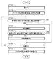
- the user places the ultraviolet sterilizer 2 on the horizontal surface 35 with the power supply unit 12 facing down, and then presses the power button 18 to turn on the power of the ultraviolet sterilizer 2 (step ST100).
- a power-on signal is issued from the power button 18 , and the power-on signal is input to the CPU 20 via the bus line 23 .
- the CPU 20 When the power-on signal is input, the CPU 20 performs power-on processing. That is, the power of the battery 17 is supplied to each part of the ultraviolet sterilizer 2 by the power supply unit 30 . Also, under the control of the CPU 20, the human sensor 14 is activated through the sensor driver 29 (step ST110).
- the radiation source is controlled by the CPU 20 as shown in FIGS.
- the ultraviolet light source 13 is operated by the driver 28, and the ultraviolet light UV is emitted from the ultraviolet light source 13 (step ST130).
- the ultraviolet rays UV are emitted from the emission window 15 and applied to the finger 36 to sterilize the finger 36.
- step ST140 When the human sensor 14 no longer detects that the finger 36 is positioned facing the exit window 15 while the ultraviolet light UV is being emitted from the ultraviolet light source 13 (NO in step ST140), the control of the CPU 20 is stopped. At the bottom, the operation of the ultraviolet light source 13 is stopped by the radiation source driver 28, and the irradiation of the ultraviolet light UV from the ultraviolet light source 13 is stopped (step ST150). The series of processing from step ST120 to step ST150 continues until the power button 18 is pressed to turn off the power (NO in step ST160).
- the CPU 20 When the power button 18 is pressed and a power off signal is emitted from the power button 18 and the power off signal is input via the bus line 23, the CPU 20 performs power off processing. That is, the power supply of the battery 17 by the power supply unit 30 is stopped, and the power of the ultraviolet sterilizer 2 is turned off (step ST170).
- the ultraviolet sterilizer 2 includes the ultraviolet source 13 that emits ultraviolet rays UV, the human sensor 14 that detects a person without contact, and the ultraviolet ray source 13 when the human sensor 14 detects a person. and a CPU 20 for irradiating ultraviolet rays UV. It is possible to sterilize a person with ultraviolet rays more hygienically than in the case of irradiating ultraviolet rays UV by touching an operation member such as a button.
- the ultraviolet sterilizer 2 does not irradiate the ultraviolet light UV from the ultraviolet light source 13 when the human sensor 14 does not detect a person. Therefore, useless irradiation of ultraviolet rays UV and useless power consumption can be suppressed.
- the CPU 20 stops irradiating the ultraviolet light source 13 with the ultraviolet light UV when the human sensor 14 stops detecting a person while the ultraviolet light source 13 is irradiating the ultraviolet light UV. Let Therefore, useless irradiation of ultraviolet rays UV and useless power consumption can be further suppressed.
- the function of irradiating ultraviolet rays based on the detection of the human sensor 14 is disabled by pressing the power button 18 to turn off the ultraviolet sterilizer 2 . Therefore, when the user does not intend to disinfect the fingers 36, such as when carrying the ultraviolet sterilizer 2, it is possible to prevent the ultraviolet ray UV from inadvertently being detected by the human sensor 14. ⁇
- the human sensor 14 senses that a human finger 36, which is a part to be sterilized, is positioned facing the exit window 15 of ultraviolet rays UV. Therefore, fingers 36 can be sterilized without waste.
- the center wavelength of ultraviolet rays UV is 200 nm or more and 230 nm or less.
- Ultraviolet UV with a center wavelength of 200 nm or more and 230 nm or less has less effect on humans than UV with a center wavelength of less than 200 nm and UV with a center wavelength of 255 nm or more, for example, over 230 nm. Therefore, it is possible to effectively sterilize at least a portion of a person, such as the fingers 36 of a person, which is to be sterilized, without using alcohol, which poses a problem that some people are not compatible with it.
- the CPU 20 causes the ultraviolet light source 13 to irradiate the ultraviolet light UV while the finger 36 is at the position facing the exit window 15, but the present invention is not limited to this.
- the CPU 20 detects that the finger 36 is at a position facing the exit window 15 by the human sensor 14, and causes the ultraviolet light source 13 to irradiate the ultraviolet light UV. After the irradiation time T set in advance has elapsed after starting, the ultraviolet light source 13 is made to stop the irradiation of the ultraviolet light UV.
- the ultraviolet sterilizer 40 of this embodiment is provided with a distance sensor 41 .
- the distance sensor 41 is arranged in the upper center of the radiation source section 42 of the ultraviolet sterilizer 40 .
- the distance sensor 41 operates when the human sensor 14 detects that the finger 36 is positioned facing the exit window 15 .
- the distance sensor 41 is, for example, an optical sensor. Specifically, the distance sensor 41 emits a pulse-modulated laser beam LL to the outside through the sensor window 43 . Then, the distance L1 to the finger 36 is measured by receiving the laser light LL reflected from the finger 36 in this case.
- the CPU 20 changes the irradiation time T according to the distance L between the finger 36 and the ultraviolet light source 13 .
- the distance sensor 41 may be a so-called TOF (Time of Flight) sensor.
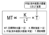
- the formula shown in FIG. 9 expresses the relationship between the target irradiation light quantity MT of the ultraviolet UV, the irradiation intensity K of the ultraviolet UV, the distance L between the finger 36 and the ultraviolet light source 13, and the irradiation time T of the ultraviolet UV.
- the target irradiation light amount MT is an irradiation light amount M of ultraviolet UV necessary and sufficient for sterilization.
- the irradiation light amount M is represented by the product of the illuminance of the ultraviolet rays UV and the irradiation time T.
- the illuminance is the luminous flux of ultraviolet rays UV incident on a unit area of an irradiation target, and the unit is mW/cm 2 .
- the unit of the amount of irradiation light which is the product of the illuminance and the irradiation time T, is mJ/cm 2 .
- the target irradiation light amount MT is proportional to the irradiation intensity K and the irradiation time T, and inversely proportional to the distance L squared. That is, the target irradiation light amount MT is obtained by the formula shown in FIG. MT ⁇ (K/L2) ⁇ T It can be expressed as.
- the target irradiation light amount MT and irradiation intensity K are constant values.
- the distance L changes depending on the position where the finger 36 is held. Therefore, by changing the irradiation time T according to the distance L, the ultraviolet rays UV of the target irradiation light amount MT are always irradiated regardless of the distance L.
- the distance measured by the distance sensor 41 is the distance L between the finger 36 and the ultraviolet source 13 .
- the arrangement of the distance sensor 41 is restricted. Therefore, it is preferable to calculate the distance L between the finger 36 and the ultraviolet light source 13 from the distance L1 measured by the distance sensor 41 and the distance L2 from the distance sensor 41 to the ultraviolet light source 13 as described above.
- the irradiation time T of the ultraviolet UV is changed according to only the distance L between the finger 36 and the ultraviolet light source 13, but this is not restrictive.
- the NVM 22 stores target irradiation light amount information 50 .
- the target irradiation light amount information 50 is information storing a target irradiation light amount MT for each bacteria and/or virus to be sterilized.
- the target irradiation light amount MT for influenza virus is 6 mJ/cm 2
- the target irradiation light amount MT for novel coronavirus is 10 mJ/cm 2 .
- a touch panel display 56 is provided in the ultraviolet sterilizer 55 of this embodiment.
- the touch panel display 56 is arranged on the back surface of the radiation source section 57 of the ultraviolet sterilizer 55 .
- a selection screen 58 is displayed on the touch panel display 56 .
- the selection screen 58 has a selection box 59 and a decision button 60 for alternatively selecting bacteria and/or viruses to be sterilized.
- the user selects bacteria and/or viruses to be sterilized from selection box 59 and selects decision button 60 .
- the CPU 20 reads the target irradiation light amount MT corresponding to the bacteria and/or virus selected in the selection box 59 from the target irradiation light amount information 50 .
- the CPU 20 changes the irradiation time T so that the irradiation light amount of the ultraviolet rays UV becomes the read target irradiation light amount MT.
- the CPU 20 of this embodiment changes the irradiation time T according to the type of bacteria and/or viruses to be sterilized in addition to the distance L between the finger 36 and the ultraviolet light source 13. .
- the irradiation intensity K is constant.
- the target irradiation light amount MT varies depending on the bacteria and/or viruses selected in selection box 59 .
- the distance L changes depending on the position where the finger 36 is held, as in the 2_1 embodiment. Therefore, by changing the irradiation time T according to the distance L and the type of bacteria and/or viruses to be sterilized, the target irradiation can always be performed regardless of the distance L and the type of bacteria and/or viruses to be sterilized.
- Ultraviolet rays UV with light quantity MT are irradiated.
- the CPU 20 causes the ultraviolet light source 13 to emit the ultraviolet light after the preset irradiation time T has elapsed after the ultraviolet light source 13 starts irradiating the ultraviolet light. to stop irradiation. Therefore, the certainty of sterilization is increased.
- the irradiation time T is changed according to the distance L between the finger 36 and the ultraviolet light source 13. Therefore, the effect of sterilization does not vary depending on the distance L. Further, in the 2_2 embodiment, the irradiation time T is changed according to not only the distance L between the finger 36 and the ultraviolet light source 13 but also the type of bacteria and/or viruses to be sterilized. Therefore, it is possible to irradiate ultraviolet rays UV for an irradiation time T suitable for the type of bacteria and/or viruses to be sterilized.
- the CPU 20 once detects the position of the finger 36 through the exit window. Next irradiation of ultraviolet rays UV is not started unless the position opposite to 15 is deviated.
- the CPU 20 when the human sensor 14 senses that the finger 36 is at a position facing the exit window 15 for a preset time even after the ultraviolet light source 13 stops irradiating the ultraviolet light UV, the CPU 20 , the next UV irradiation may be started.
- the irradiation time T may be set to a constant value regardless of the distance L between the finger 36 and the ultraviolet light source 13 and the type of bacteria and/or viruses to be sterilized.
- the distance L between the finger 36 and the ultraviolet light source 13 may be set to a constant value, and the irradiation time T may be changed according to only the type of bacteria and/or viruses to be sterilized.
- the CPU 20 causes the ultraviolet light source 13 to irradiate the ultraviolet ray UV in the mode of the first embodiment, and after the ultraviolet light source 13 starts irradiating the ultraviolet ray UV,
- the mode of the 2_1 embodiment and the 2_2 embodiment in which the UV irradiation of the UV source 13 is stopped after a preset irradiation time T has elapsed may be switchable as the operation mode.
- the irradiation intensity K may be changed according to at least one of the distance L between the finger 36 and the ultraviolet light source 13 and the type of bacteria and/or viruses to be sterilized. .
- the ultraviolet sterilizer 65 of this embodiment includes a radiation source section 66, a connection section 67, and a power supply section 68, and the user can use the connection section 67 by holding the connection section 67 with a hand 71. It is possible.
- An invalidation button 69 is provided in the radiation source section 66 .
- the invalidation button 69 is arranged on the back surface of the radiation source section 66 .
- the disabling button 69 is a button for disabling the function of irradiating ultraviolet rays UV upon detection by the human sensor 14, and is an example of the "operation member" according to the technology of the present disclosure.
- An irradiation button 70 is provided on the connecting portion 67 .
- the irradiation button 70 is arranged on the front surface of the connecting portion 67 at a position where it can be pressed with the index finger of the user's hand 71 holding the connecting portion 67 .
- the irradiation button 70 is a button for instructing the irradiation of ultraviolet rays UV.
- the irradiation button 70 has the invalidation button 69 turned on, and the function of irradiating the ultraviolet rays UV is invalidated by the detection of the human sensor 14. The feature is enabled only if
- step ST200 when the user turns on the disable button 69 (YES in step ST200), the sensor driver 29 operates the motion sensor 14 under the control of the CPU 20. be stopped. Instead, the function of irradiation button 70 is activated (step ST210).
- the radiation source driver 28 When the irradiation button 70 is turned on by the user (YES in step ST220), the radiation source driver 28 operates the ultraviolet light source 13 under the control of the CPU 20, and the ultraviolet light source 13 emits ultraviolet light UV. After the preset irradiation time T has elapsed (YES in step ST240), the operation of the ultraviolet light source 13 is stopped by the radiation source driver 28 under the control of the CPU 20, and the irradiation of the ultraviolet light UV from the ultraviolet light source 13 is stopped. (step ST250).
- the function of irradiating ultraviolet rays UV is disabled by sensing the human sensor 14 in response to the operation of the disabling button 69 . Then, according to the operation of the irradiation button 70 that can be operated with the hand 71 holding the connecting portion 67, the ultraviolet light source 13 emits the ultraviolet light UV. Therefore, the ultraviolet sterilizer 65 can be used while holding the connecting portion 67 with the hand 71 . Not only the fingers 36 but also the whole body, soles of shoes, chairs, desks, handrails, etc. can be easily sterilized.
- the ultraviolet UV is irradiated while the irradiation button 70 is turned on, and when the finger is removed from the irradiation button 70, the irradiation button 70 is turned off. In such a case, the irradiation of ultraviolet rays UV may be stopped.
- the invalidation button 69 and the irradiation button 70 may be integrally configured as a two-stage push button. Specifically, a first-step (half-press) disables the function of irradiating ultraviolet rays UV upon detection by the human sensor 14, and a second-step (full-press) causes ultraviolet rays UV to be emitted. Alternatively, a first-step (half-press) activates the function of irradiating ultraviolet UV by sensing the human sensor 14, and only when the human sensor 14 detects a person, a second-step (full-press) presses the ultraviolet UV. may be irradiated.
- the NVM 22 of the ultraviolet sterilizer 75 of the present embodiment stores cumulative irradiation light amount information 80 and irradiation prohibition conditions 81 .
- the cumulative irradiation light amount information 80 stores the cumulative irradiation light amount MC of ultraviolet rays UV for each person (see FIG. 16).
- the irradiation prohibition condition 81 is a condition for prohibiting the irradiation of ultraviolet rays UV, which is set based on the cumulative irradiation light amount MC (see FIG. 17).
- the NVM 22 is an example of a “storage unit” according to the technology of the present disclosure.
- the ultraviolet sterilizer 75 has a camera 85, a camera driver 86, and a touch panel display 87.
- the camera 85 is built in the radiation source section 76 (see FIG. 18) of the ultraviolet sterilizer 75 together with the ultraviolet light source 13 and the human sensor 14 .
- Camera 85 is operated by camera driver 86 under the control of CPU 20 . Specifically, the camera 85 is activated when the human sensor 14 senses that the finger 36 is positioned facing the exit window 15 .
- the camera 85 has an image pickup element that picks up subject light incident through the objective window 88 .
- the touch panel display 87 is arranged on the back surface of the radiation source section 76 (see FIG. 18), similarly to the ultraviolet sterilizer 55 of the 2_2 embodiment.
- the camera 85 captures a face image 90 of a person holding the finger 36 over a position facing the exit window 15 .
- Camera 85 outputs face image 90 to CPU 20 .
- the face image 90 is an example of "identification information" according to the technology of the present disclosure.
- the CPU 20 By activating the operation program 25, the CPU 20 functions as a facial feature extractor 95, an irradiation light amount calculator 96, and a memory controller 97 in cooperation with the RAM 21 and the like.
- a facial image 90 is input from the camera 85 to the facial feature extraction unit 95 . That is, the facial feature extraction unit 95 acquires the facial image 90 as identification information.
- a facial feature extracting unit 95 extracts the size of each facial component such as eyebrows, eyes, nose, mouth, and ears from the facial image 90 as facial features.
- the facial feature extraction unit 95 also extracts, as facial features, the positions of the feature points of each constituent part such as the outer corner of the eyebrow, the inner corner of the eye, the outer corner of the eye, the tip of the nose, and the corner of the mouth, and the positional relationship of each constituent part such as the distance between the inner corners of the eyes.
- the facial feature extractor 95 outputs facial feature information 100 summarizing the extracted facial features to the storage controller 97 .
- the irradiation light amount calculation unit 96 calculates the irradiation light amount M of the ultraviolet UV irradiated to the finger 36 based on the irradiation intensity K of the ultraviolet UV, the distance L between the finger 36 and the ultraviolet light source 13, the irradiation time T of the ultraviolet UV, and the like. do.
- the irradiation light amount calculator 96 calculates the irradiation light amount M when the irradiation of the ultraviolet rays UV by the ultraviolet light source 13 is stopped.
- the irradiation light amount calculation section 96 outputs the calculated irradiation light amount M to the storage control section 97 .
- the storage control unit 97 changes the irradiation light amount M from the irradiation light amount calculation unit 96 to It is added to the cumulative irradiation light amount MC of the registered facial feature information 100 . If the facial feature information 100 that matches the facial feature information 100 from the facial feature extraction unit 95 is not registered in the cumulative irradiation light amount information 80, the storage control unit 97 replaces the column of the facial feature information 100 with the cumulative irradiation light amount information 80. to be newly established.
- the irradiation light amount M from the irradiation light amount calculation unit 96 is registered as the cumulative irradiation light amount MC in the newly established column.
- the storage control unit 97 resets the cumulative irradiation light quantity MC to zero at regular intervals, for example, at monthly intervals.
- “matching" of the facial feature information 100 here includes not only perfect matching but also cases in which the degree of matching of the facial feature information 100 satisfies preset conditions.
- the degree of matching is, for example, registered in the facial feature information 100 from the facial feature extraction unit 95 and the cumulative irradiation light amount information 80 when a plurality of facial features constituting the facial feature information 100 are used as elements of a multidimensional vector. This is the Euclidean distance from the facial feature information 100 .
- the irradiation prohibition condition 81 is that the cumulative irradiation light amount MC is greater than 1000 mJ/cm 2 (cumulative irradiation light amount MC>1000).
- 1000 mJ/cm 2 is an example of a "threshold" according to the technology of the present disclosure.
- the CPU 20 reads the cumulative irradiation light amount MC corresponding to the facial feature information 100 from the facial feature extraction unit 95 from the cumulative irradiation light amount information 80 prior to irradiation with ultraviolet rays UV.
- the CPU 20 determines whether or not the read accumulated irradiation light quantity MC satisfies the irradiation prohibition condition 81 .
- the CPU 20 does not instruct the ultraviolet light source 13 to irradiate the ultraviolet ray UV, or instructs the ultraviolet ray source 13 to irradiate the ultraviolet ray UV. output a signal to prohibit
- FIG. 18 shows an example of determining whether or not the accumulated irradiation light amount MC satisfies the irradiation prohibition condition 81 for a person whose facial feature information 100 is "X".
- the cumulative irradiation light amount MC of the person whose facial feature information 100 is "X” is 1005 mJ/cm 2 , which exceeds the threshold of 1000 mJ/cm 2 of the irradiation prohibition condition 81, and the facial feature information 100 is An example of not irradiating ultraviolet rays UV to a person of "X" is shown.
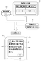
- the CPU 20 causes the touch panel display 87 to display the warning screen 105 .
- a message 106 and an OK button 107 are displayed to the effect that the irradiation of the ultraviolet UV is refrained because the accumulated irradiation light quantity MC exceeds the threshold value.
- the warning screen 105 disappears when the OK button 107 is selected.
- the facial feature extraction unit 95 of the CPU 20 acquires the facial image 90, which is identification information for identifying a person.
- the storage control unit 97 of the CPU 20 stores the cumulative irradiation light amount MC of the ultraviolet UV in the NVM 22 for each person identified by the face image 90 . Therefore, it is possible to manage the cumulative irradiation light amount MC of ultraviolet rays UV for each person.
- the ultraviolet sterilizer 75 does not irradiate the ultraviolet light UV from the ultraviolet light source 13 to a person whose cumulative irradiation light amount MC exceeds a preset threshold value. Therefore, excessive irradiation of ultraviolet rays UV can be prevented.
- the technology of the present disclosure uses ultraviolet UV, which has relatively little effect on humans, excessive irradiation should be avoided.
- the identification information for identifying a person is not limited to the face image 90 illustrated. It may be a personal identification ID recorded on an ID (Identification Data) card. In this case, a card reader is used to read the personal identification ID from the ID card, and the personal identification ID is input to the CPU 20 from the card reader.
- ID Identity Data
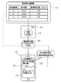
- the distribution control unit 115 performs control to distribute the cumulative irradiation light amount MC registered in the cumulative irradiation light amount information 111 to the terminal 110 registered in the terminal information, for example, via a WAN (Wide Area Network) such as the Internet.
- the terminal 110 is an example of an “external device” according to the technology of the present disclosure.
- the terminal 110 displays the notification screen 119 on the touch panel display 118 upon receiving the delivery of the cumulative irradiation light amount MC.
- the notification screen 119 displays a message 120 including the distributed cumulative irradiation light amount MC and the difference between the cumulative irradiation light amount MC and the threshold.
- FIG. 19 shows an example in which the terminal 110 owned by the person whose facial feature information 100 is "B” and whose terminal information is "U0002" is distributed with the cumulative irradiation light amount MC "700 mJ/cm 2 ". ing.
- the 4_2 embodiment includes the distribution control unit 115 that controls distribution of the cumulative irradiation light amount MC to the terminal 110, which is an external device. Therefore, the accumulated irradiation light amount MC can be used by an external device, such as by displaying the notification screen 119 on the touch panel display 118 .
- the terminal 110 may store the cumulative irradiation light amount information MC.
- the external device may be a management server or the like that collectively manages the cumulative irradiation light amount MC.
- the motion sensor 14 may be operated all the time after the power of the ultraviolet sterilizer is turned on, or may be operated intermittently.
- the central wavelength of ultraviolet rays UV is set to 200 nm or more and 230 nm or less, but it is not limited to this.
- Ultraviolet rays UV having a central wavelength of 190 nm called deep ultraviolet rays and a central wavelength of 380 nm called near ultraviolet rays (center wavelengths of 190 nm or more and 380 nm or less) may be used.
- ultraviolet rays UV of a broad wavelength range are emitted from the ultraviolet light source 15, and the emission window 15 is provided with a band-pass filter function for transmitting ultraviolet rays UV of a specific wavelength, thereby obtaining ultraviolet rays UV of a desired central wavelength.
- a bandpass filter between the ultraviolet light source 13 and the exit window 15, ultraviolet light UV with a desired center wavelength may be obtained.
- the finger 36 was exemplified as a part to be sterilized, which is at least part of a person, but it is not limited to this.
- an ultraviolet sterilizer is installed on the ceiling and/or wall of a room, a human sensor detects a person who stops at the place where the ultraviolet sterilizer is installed, and the upper or lower body or the whole body of the person is irradiated with ultraviolet UV. good too.
- an ultraviolet sterilizer may be installed facing the floor, and a human sensor may detect a person who stops at the location where the ultraviolet sterilizer is installed, and the person's feet (shoes) may be irradiated with ultraviolet UV.
- the hardware structure of the processing unit (processing unit) that executes various processes such as the facial feature extraction unit 95, the irradiation light amount calculation unit 96, the storage control unit 97, and the distribution control unit 115 can use various processors shown below.
- processors in addition to the CPU 20, which is a general-purpose processor that executes software (operation program 25) and functions as various processing units, FPGA (Field Programmable Gate Array), etc., whose circuit configuration can be changed after manufacturing Programmable Logic Device (PLD), which is a processor, and/or ASIC (Application Specific Integrated Circuit), etc. etc. are included.
- One processing unit may be configured with one of these various processors, or a combination of two or more processors of the same or different type (for example, a combination of a plurality of FPGAs and/or a CPU and combination with FPGA). Also, a plurality of processing units may be configured by one processor.
- a single processor is configured by combining one or more CPUs and software.
- a processor functions as multiple processing units.
- SoC System On Chip
- a processor that realizes the functions of the entire system including multiple processing units with a single IC (Integrated Circuit) chip. be.
- the various processing units are configured using one or more of the above various processors as a hardware structure.
- an electric circuit combining circuit elements such as semiconductor elements can be used.
- the control unit is not limited to the processor.
- a combination of relatively simple logic circuits such as comparators may be used to control the ultraviolet light source 13 to irradiate the ultraviolet light UV when the human sensor 14 detects a person.
- the configuration is simpler than that of a processor, it is possible to reduce the frequency of occurrence of failures such as freezing, and also to reduce power consumption.
- the processor such as the CPU 20, it is possible to more reliably control the ultraviolet light source 13 to irradiate the ultraviolet light UV when the human sensor 14 detects a person.
- more advanced processing such as acquiring identification information for identifying a person and storing the cumulative irradiation light amount of ultraviolet rays for each person identified by the identification information can be performed. becomes possible.
- the technology of the present disclosure can also appropriately combine various embodiments and/or various modifications described above. Moreover, it is needless to say that various configurations can be employed without departing from the scope of the present invention without being limited to the above embodiments. Furthermore, the technology of the present disclosure extends to storage media that non-temporarily store programs in addition to programs.
- a and/or B is synonymous with “at least one of A and B.” That is, “A and/or B” means that only A, only B, or a combination of A and B may be used.
- a and/or B means that only A, only B, or a combination of A and B may be used.
Landscapes
- Health & Medical Sciences (AREA)
- Epidemiology (AREA)
- Life Sciences & Earth Sciences (AREA)
- Animal Behavior & Ethology (AREA)
- General Health & Medical Sciences (AREA)
- Public Health (AREA)
- Veterinary Medicine (AREA)
- Apparatus For Disinfection Or Sterilisation (AREA)
Priority Applications (1)
| Application Number | Priority Date | Filing Date | Title |
|---|---|---|---|
| JP2023505146A JPWO2022190606A1 (https=) | 2021-03-12 | 2022-01-06 |
Applications Claiming Priority (2)
| Application Number | Priority Date | Filing Date | Title |
|---|---|---|---|
| JP2021040688 | 2021-03-12 | ||
| JP2021-040688 | 2021-03-12 |
Publications (1)
| Publication Number | Publication Date |
|---|---|
| WO2022190606A1 true WO2022190606A1 (ja) | 2022-09-15 |
Family
ID=83227246
Family Applications (1)
| Application Number | Title | Priority Date | Filing Date |
|---|---|---|---|
| PCT/JP2022/000257 Ceased WO2022190606A1 (ja) | 2021-03-12 | 2022-01-06 | 紫外線殺菌装置、紫外線殺菌装置の作動方法、紫外線殺菌装置の作動プログラム |
Country Status (2)
| Country | Link |
|---|---|
| JP (1) | JPWO2022190606A1 (https=) |
| WO (1) | WO2022190606A1 (https=) |
Cited By (1)
| Publication number | Priority date | Publication date | Assignee | Title |
|---|---|---|---|---|
| EP4295868A4 (en) * | 2021-03-31 | 2024-08-07 | Daikin Industries, Ltd. | PROCESSING DEVICE, UV EMISSION DEVICE AND UV EMISSION METHOD |
Citations (6)
| Publication number | Priority date | Publication date | Assignee | Title |
|---|---|---|---|---|
| JP2003265583A (ja) * | 2002-03-15 | 2003-09-24 | Skg:Kk | 噴霧式手先等消毒装置体 |
| JP2017113648A (ja) * | 2017-03-31 | 2017-06-29 | 株式会社トクヤマ | 紫外線殺菌装置 |
| WO2017135190A1 (ja) * | 2016-02-02 | 2017-08-10 | ウシオ電機株式会社 | 殺菌装置 |
| WO2019164810A1 (en) * | 2018-02-20 | 2019-08-29 | Freestyle Partners, LLC | Portable and disposable far-uvc device |
| WO2019190967A1 (en) * | 2018-03-30 | 2019-10-03 | Uv Partners, Inc. | Disinfection behavior tracking and ranking |
| WO2020226137A1 (ja) * | 2019-05-07 | 2020-11-12 | 株式会社M&Cデザイン | 迅速な手指消毒方法及び迅速手指消毒装置 |
-
2022
- 2022-01-06 JP JP2023505146A patent/JPWO2022190606A1/ja not_active Abandoned
- 2022-01-06 WO PCT/JP2022/000257 patent/WO2022190606A1/ja not_active Ceased
Patent Citations (6)
| Publication number | Priority date | Publication date | Assignee | Title |
|---|---|---|---|---|
| JP2003265583A (ja) * | 2002-03-15 | 2003-09-24 | Skg:Kk | 噴霧式手先等消毒装置体 |
| WO2017135190A1 (ja) * | 2016-02-02 | 2017-08-10 | ウシオ電機株式会社 | 殺菌装置 |
| JP2017113648A (ja) * | 2017-03-31 | 2017-06-29 | 株式会社トクヤマ | 紫外線殺菌装置 |
| WO2019164810A1 (en) * | 2018-02-20 | 2019-08-29 | Freestyle Partners, LLC | Portable and disposable far-uvc device |
| WO2019190967A1 (en) * | 2018-03-30 | 2019-10-03 | Uv Partners, Inc. | Disinfection behavior tracking and ranking |
| WO2020226137A1 (ja) * | 2019-05-07 | 2020-11-12 | 株式会社M&Cデザイン | 迅速な手指消毒方法及び迅速手指消毒装置 |
Cited By (2)
| Publication number | Priority date | Publication date | Assignee | Title |
|---|---|---|---|---|
| EP4295868A4 (en) * | 2021-03-31 | 2024-08-07 | Daikin Industries, Ltd. | PROCESSING DEVICE, UV EMISSION DEVICE AND UV EMISSION METHOD |
| US12350391B2 (en) | 2021-03-31 | 2025-07-08 | Daikin Industries, Ltd. | Processing device, UV emission device, and UV emission method |
Also Published As
| Publication number | Publication date |
|---|---|
| JPWO2022190606A1 (https=) | 2022-09-15 |
Similar Documents
| Publication | Publication Date | Title |
|---|---|---|
| US11337754B2 (en) | Skin treatment apparatus utilising intense pulsed light (IPL) | |
| US10918750B2 (en) | Portable light fastening assembly | |
| US10835628B2 (en) | UV germicidal system, method, and device thereof | |
| US9005262B2 (en) | Radiation-based dermatological devices and methods | |
| US11287856B2 (en) | Electronic apparatus and controlling method | |
| US11071797B2 (en) | Mobile devices having disinfection light sources | |
| US20200360718A1 (en) | Laser Therapy Device and Method of Use | |
| EP1610265A1 (en) | Camera, light source control method, and computer program | |
| JP2019512847A (ja) | ミラーコンポーネント用の適応照明システム、及び適応照明システムを制御する方法 | |
| KR102226320B1 (ko) | 두피 케어용 광 출력 기기 및 그의 제어 방법 | |
| WO2022190606A1 (ja) | 紫外線殺菌装置、紫外線殺菌装置の作動方法、紫外線殺菌装置の作動プログラム | |
| JP7236660B2 (ja) | 浄化方法、浄化装置及び浄化システム | |
| US20220193282A1 (en) | System for mobile smart devices that sterilize targets and increase the transparency of the process | |
| KR20210034969A (ko) | Uvb led 전반 조명장치 및 그 제어 방법 | |
| TW202408597A (zh) | 抑菌裝置及方法 | |
| US12128431B2 (en) | Purifying apparatus and purifying method | |
| US20240058489A1 (en) | Use of polarized radiation for detecting touch on a radiation exit window | |
| KR20210025571A (ko) | 두피 케어용 광 출력 기기 및 그의 제어 방법 | |
| WO2020179136A1 (ja) | 対光反射計測装置、対光反射計測方法、及び対光反射計測プログラム | |
| US11867498B2 (en) | Sprayer comprising detection system for early power-off | |
| KR100760709B1 (ko) | 다중 광원을 이용하는 피부 관찰 장치 | |
| US20070239145A1 (en) | System and method to assist in the treatment of skin conditions | |
| CN116710152A (zh) | 用于对房间中的空气安全且有效地进行消毒的系统和方法 |
Legal Events
| Date | Code | Title | Description |
|---|---|---|---|
| 121 | Ep: the epo has been informed by wipo that ep was designated in this application |
Ref document number: 22766574 Country of ref document: EP Kind code of ref document: A1 |
|
| WWE | Wipo information: entry into national phase |
Ref document number: 2023505146 Country of ref document: JP |
|
| NENP | Non-entry into the national phase |
Ref country code: DE |
|
| 122 | Ep: pct application non-entry in european phase |
Ref document number: 22766574 Country of ref document: EP Kind code of ref document: A1 |