WO2022186376A1 - Battery pack management system - Google Patents
Battery pack management system Download PDFInfo
- Publication number
- WO2022186376A1 WO2022186376A1 PCT/JP2022/009391 JP2022009391W WO2022186376A1 WO 2022186376 A1 WO2022186376 A1 WO 2022186376A1 JP 2022009391 W JP2022009391 W JP 2022009391W WO 2022186376 A1 WO2022186376 A1 WO 2022186376A1
- Authority
- WO
- WIPO (PCT)
- Prior art keywords
- battery management
- control circuit
- communication circuit
- assembled battery
- management system
- Prior art date
Links
- 238000004891 communication Methods 0.000 claims abstract description 294
- 238000012544 monitoring process Methods 0.000 claims abstract description 95
- 210000004027 cell Anatomy 0.000 claims abstract description 93
- 210000000352 storage cell Anatomy 0.000 claims abstract description 38
- 230000005856 abnormality Effects 0.000 claims description 62
- 230000004913 activation Effects 0.000 claims description 12
- 230000003213 activating effect Effects 0.000 claims description 5
- 230000007704 transition Effects 0.000 abstract 1
- 238000005259 measurement Methods 0.000 description 23
- 238000010586 diagram Methods 0.000 description 21
- 235000005633 Chrysanthemum balsamita Nutrition 0.000 description 15
- 230000007274 generation of a signal involved in cell-cell signaling Effects 0.000 description 13
- 241000723353 Chrysanthemum Species 0.000 description 8
- 241000132023 Bellis perennis Species 0.000 description 7
- 238000001514 detection method Methods 0.000 description 6
- 230000004048 modification Effects 0.000 description 6
- 238000012986 modification Methods 0.000 description 6
- 238000004590 computer program Methods 0.000 description 5
- 230000006870 function Effects 0.000 description 4
- 230000002159 abnormal effect Effects 0.000 description 3
- 239000000470 constituent Substances 0.000 description 3
- 239000003990 capacitor Substances 0.000 description 2
- 238000003745 diagnosis Methods 0.000 description 2
- 238000000034 method Methods 0.000 description 2
- 230000002123 temporal effect Effects 0.000 description 2
- HBBGRARXTFLTSG-UHFFFAOYSA-N Lithium ion Chemical compound [Li+] HBBGRARXTFLTSG-UHFFFAOYSA-N 0.000 description 1
- 230000000694 effects Effects 0.000 description 1
- 230000010354 integration Effects 0.000 description 1
- 238000007562 laser obscuration time method Methods 0.000 description 1
- 229910001416 lithium ion Inorganic materials 0.000 description 1
- 230000007774 longterm Effects 0.000 description 1
- 239000000463 material Substances 0.000 description 1
- 238000000691 measurement method Methods 0.000 description 1
- 230000008569 process Effects 0.000 description 1
- 230000009467 reduction Effects 0.000 description 1
- 230000001172 regenerating effect Effects 0.000 description 1
- 230000003252 repetitive effect Effects 0.000 description 1
- 230000009131 signaling function Effects 0.000 description 1
Images


Classifications
-
- H—ELECTRICITY
- H02—GENERATION; CONVERSION OR DISTRIBUTION OF ELECTRIC POWER
- H02J—CIRCUIT ARRANGEMENTS OR SYSTEMS FOR SUPPLYING OR DISTRIBUTING ELECTRIC POWER; SYSTEMS FOR STORING ELECTRIC ENERGY
- H02J7/00—Circuit arrangements for charging or depolarising batteries or for supplying loads from batteries
- H02J7/007—Regulation of charging or discharging current or voltage
- H02J7/00712—Regulation of charging or discharging current or voltage the cycle being controlled or terminated in response to electric parameters
-
- G—PHYSICS
- G01—MEASURING; TESTING
- G01R—MEASURING ELECTRIC VARIABLES; MEASURING MAGNETIC VARIABLES
- G01R19/00—Arrangements for measuring currents or voltages or for indicating presence or sign thereof
- G01R19/0084—Arrangements for measuring currents or voltages or for indicating presence or sign thereof measuring voltage only
-
- G—PHYSICS
- G01—MEASURING; TESTING
- G01R—MEASURING ELECTRIC VARIABLES; MEASURING MAGNETIC VARIABLES
- G01R31/00—Arrangements for testing electric properties; Arrangements for locating electric faults; Arrangements for electrical testing characterised by what is being tested not provided for elsewhere
- G01R31/36—Arrangements for testing, measuring or monitoring the electrical condition of accumulators or electric batteries, e.g. capacity or state of charge [SoC]
- G01R31/371—Arrangements for testing, measuring or monitoring the electrical condition of accumulators or electric batteries, e.g. capacity or state of charge [SoC] with remote indication, e.g. on external chargers
-
- G—PHYSICS
- G01—MEASURING; TESTING
- G01R—MEASURING ELECTRIC VARIABLES; MEASURING MAGNETIC VARIABLES
- G01R31/00—Arrangements for testing electric properties; Arrangements for locating electric faults; Arrangements for electrical testing characterised by what is being tested not provided for elsewhere
- G01R31/36—Arrangements for testing, measuring or monitoring the electrical condition of accumulators or electric batteries, e.g. capacity or state of charge [SoC]
- G01R31/382—Arrangements for monitoring battery or accumulator variables, e.g. SoC
- G01R31/3835—Arrangements for monitoring battery or accumulator variables, e.g. SoC involving only voltage measurements
-
- G—PHYSICS
- G01—MEASURING; TESTING
- G01R—MEASURING ELECTRIC VARIABLES; MEASURING MAGNETIC VARIABLES
- G01R31/00—Arrangements for testing electric properties; Arrangements for locating electric faults; Arrangements for electrical testing characterised by what is being tested not provided for elsewhere
- G01R31/36—Arrangements for testing, measuring or monitoring the electrical condition of accumulators or electric batteries, e.g. capacity or state of charge [SoC]
- G01R31/392—Determining battery ageing or deterioration, e.g. state of health
-
- G—PHYSICS
- G01—MEASURING; TESTING
- G01R—MEASURING ELECTRIC VARIABLES; MEASURING MAGNETIC VARIABLES
- G01R31/00—Arrangements for testing electric properties; Arrangements for locating electric faults; Arrangements for electrical testing characterised by what is being tested not provided for elsewhere
- G01R31/36—Arrangements for testing, measuring or monitoring the electrical condition of accumulators or electric batteries, e.g. capacity or state of charge [SoC]
- G01R31/396—Acquisition or processing of data for testing or for monitoring individual cells or groups of cells within a battery
-
- H—ELECTRICITY
- H01—ELECTRIC ELEMENTS
- H01M—PROCESSES OR MEANS, e.g. BATTERIES, FOR THE DIRECT CONVERSION OF CHEMICAL ENERGY INTO ELECTRICAL ENERGY
- H01M10/00—Secondary cells; Manufacture thereof
- H01M10/42—Methods or arrangements for servicing or maintenance of secondary cells or secondary half-cells
- H01M10/425—Structural combination with electronic components, e.g. electronic circuits integrated to the outside of the casing
-
- H—ELECTRICITY
- H01—ELECTRIC ELEMENTS
- H01M—PROCESSES OR MEANS, e.g. BATTERIES, FOR THE DIRECT CONVERSION OF CHEMICAL ENERGY INTO ELECTRICAL ENERGY
- H01M10/00—Secondary cells; Manufacture thereof
- H01M10/42—Methods or arrangements for servicing or maintenance of secondary cells or secondary half-cells
- H01M10/48—Accumulators combined with arrangements for measuring, testing or indicating the condition of cells, e.g. the level or density of the electrolyte
- H01M10/482—Accumulators combined with arrangements for measuring, testing or indicating the condition of cells, e.g. the level or density of the electrolyte for several batteries or cells simultaneously or sequentially
-
- H—ELECTRICITY
- H01—ELECTRIC ELEMENTS
- H01M—PROCESSES OR MEANS, e.g. BATTERIES, FOR THE DIRECT CONVERSION OF CHEMICAL ENERGY INTO ELECTRICAL ENERGY
- H01M50/00—Constructional details or processes of manufacture of the non-active parts of electrochemical cells other than fuel cells, e.g. hybrid cells
- H01M50/50—Current conducting connections for cells or batteries
- H01M50/502—Interconnectors for connecting terminals of adjacent batteries; Interconnectors for connecting cells outside a battery casing
- H01M50/509—Interconnectors for connecting terminals of adjacent batteries; Interconnectors for connecting cells outside a battery casing characterised by the type of connection, e.g. mixed connections
- H01M50/51—Connection only in series
-
- H—ELECTRICITY
- H02—GENERATION; CONVERSION OR DISTRIBUTION OF ELECTRIC POWER
- H02J—CIRCUIT ARRANGEMENTS OR SYSTEMS FOR SUPPLYING OR DISTRIBUTING ELECTRIC POWER; SYSTEMS FOR STORING ELECTRIC ENERGY
- H02J7/00—Circuit arrangements for charging or depolarising batteries or for supplying loads from batteries
- H02J7/00032—Circuit arrangements for charging or depolarising batteries or for supplying loads from batteries characterised by data exchange
-
- H—ELECTRICITY
- H02—GENERATION; CONVERSION OR DISTRIBUTION OF ELECTRIC POWER
- H02J—CIRCUIT ARRANGEMENTS OR SYSTEMS FOR SUPPLYING OR DISTRIBUTING ELECTRIC POWER; SYSTEMS FOR STORING ELECTRIC ENERGY
- H02J7/00—Circuit arrangements for charging or depolarising batteries or for supplying loads from batteries
- H02J7/0013—Circuit arrangements for charging or depolarising batteries or for supplying loads from batteries acting upon several batteries simultaneously or sequentially
- H02J7/0014—Circuits for equalisation of charge between batteries
- H02J7/0019—Circuits for equalisation of charge between batteries using switched or multiplexed charge circuits
-
- H—ELECTRICITY
- H02—GENERATION; CONVERSION OR DISTRIBUTION OF ELECTRIC POWER
- H02J—CIRCUIT ARRANGEMENTS OR SYSTEMS FOR SUPPLYING OR DISTRIBUTING ELECTRIC POWER; SYSTEMS FOR STORING ELECTRIC ENERGY
- H02J7/00—Circuit arrangements for charging or depolarising batteries or for supplying loads from batteries
- H02J7/0047—Circuit arrangements for charging or depolarising batteries or for supplying loads from batteries with monitoring or indicating devices or circuits
-
- H—ELECTRICITY
- H02—GENERATION; CONVERSION OR DISTRIBUTION OF ELECTRIC POWER
- H02J—CIRCUIT ARRANGEMENTS OR SYSTEMS FOR SUPPLYING OR DISTRIBUTING ELECTRIC POWER; SYSTEMS FOR STORING ELECTRIC ENERGY
- H02J7/00—Circuit arrangements for charging or depolarising batteries or for supplying loads from batteries
- H02J7/14—Circuit arrangements for charging or depolarising batteries or for supplying loads from batteries for charging batteries from dynamo-electric generators driven at varying speed, e.g. on vehicle
- H02J7/1423—Circuit arrangements for charging or depolarising batteries or for supplying loads from batteries for charging batteries from dynamo-electric generators driven at varying speed, e.g. on vehicle with multiple batteries
-
- H—ELECTRICITY
- H01—ELECTRIC ELEMENTS
- H01M—PROCESSES OR MEANS, e.g. BATTERIES, FOR THE DIRECT CONVERSION OF CHEMICAL ENERGY INTO ELECTRICAL ENERGY
- H01M10/00—Secondary cells; Manufacture thereof
- H01M10/42—Methods or arrangements for servicing or maintenance of secondary cells or secondary half-cells
- H01M10/425—Structural combination with electronic components, e.g. electronic circuits integrated to the outside of the casing
- H01M2010/4271—Battery management systems including electronic circuits, e.g. control of current or voltage to keep battery in healthy state, cell balancing
-
- H—ELECTRICITY
- H01—ELECTRIC ELEMENTS
- H01M—PROCESSES OR MEANS, e.g. BATTERIES, FOR THE DIRECT CONVERSION OF CHEMICAL ENERGY INTO ELECTRICAL ENERGY
- H01M10/00—Secondary cells; Manufacture thereof
- H01M10/42—Methods or arrangements for servicing or maintenance of secondary cells or secondary half-cells
- H01M10/425—Structural combination with electronic components, e.g. electronic circuits integrated to the outside of the casing
- H01M2010/4278—Systems for data transfer from batteries, e.g. transfer of battery parameters to a controller, data transferred between battery controller and main controller
-
- H—ELECTRICITY
- H02—GENERATION; CONVERSION OR DISTRIBUTION OF ELECTRIC POWER
- H02J—CIRCUIT ARRANGEMENTS OR SYSTEMS FOR SUPPLYING OR DISTRIBUTING ELECTRIC POWER; SYSTEMS FOR STORING ELECTRIC ENERGY
- H02J2207/00—Indexing scheme relating to details of circuit arrangements for charging or depolarising batteries or for supplying loads from batteries
- H02J2207/20—Charging or discharging characterised by the power electronics converter
-
- H—ELECTRICITY
- H02—GENERATION; CONVERSION OR DISTRIBUTION OF ELECTRIC POWER
- H02J—CIRCUIT ARRANGEMENTS OR SYSTEMS FOR SUPPLYING OR DISTRIBUTING ELECTRIC POWER; SYSTEMS FOR STORING ELECTRIC ENERGY
- H02J2310/00—The network for supplying or distributing electric power characterised by its spatial reach or by the load
- H02J2310/40—The network being an on-board power network, i.e. within a vehicle
- H02J2310/48—The network being an on-board power network, i.e. within a vehicle for electric vehicles [EV] or hybrid vehicles [HEV]
-
- Y—GENERAL TAGGING OF NEW TECHNOLOGICAL DEVELOPMENTS; GENERAL TAGGING OF CROSS-SECTIONAL TECHNOLOGIES SPANNING OVER SEVERAL SECTIONS OF THE IPC; TECHNICAL SUBJECTS COVERED BY FORMER USPC CROSS-REFERENCE ART COLLECTIONS [XRACs] AND DIGESTS
- Y02—TECHNOLOGIES OR APPLICATIONS FOR MITIGATION OR ADAPTATION AGAINST CLIMATE CHANGE
- Y02E—REDUCTION OF GREENHOUSE GAS [GHG] EMISSIONS, RELATED TO ENERGY GENERATION, TRANSMISSION OR DISTRIBUTION
- Y02E60/00—Enabling technologies; Technologies with a potential or indirect contribution to GHG emissions mitigation
- Y02E60/10—Energy storage using batteries
Definitions
- This disclosure relates to an assembled battery management system.
- the assembled battery management system has a plurality of cell monitoring units that measure the voltage of the storage cells, and a control circuit that controls the plurality of cell monitoring units. Multiple cell monitoring units and control circuits are daisy chained.
- the present disclosure aims to solve such problems, and aims to provide an assembled battery management system capable of suppressing power consumption.
- an assembled battery management system for managing an assembled battery having a plurality of storage cells connected in series or in parallel, a cell monitoring unit that is connected to the storage cells and measures the output voltage of at least one of the plurality of storage cells; a battery management unit that manages the assembled battery; a communication network, wherein the battery management unit includes a first communication circuit connected to the first communication network, and a second communication network connected to a host system of the assembled battery management system.
- the assembled battery management system has two communication circuits, a control circuit that controls the battery management unit, and a control circuit power supply that supplies power to the control circuit.
- a low power consumption mode that consumes less power, and in the low power consumption mode, at least one of the power supply for the control circuit, the control circuit, and the second communication circuit is stopped;
- the one communication circuit activates at least one of the control circuit power supply, the control circuit, and the second communication circuit when the low power consumption mode is shifted to the normal mode.
- another aspect of the assembled battery management system is an assembled battery management system for managing an assembled battery having a plurality of storage cells connected in series or in parallel, A cell monitoring unit that is connected to a plurality of storage cells and measures at least one output voltage of the plurality of storage cells, a battery management unit that manages the assembled battery, and a connection between the cell monitoring unit and the battery management unit.
- the battery management unit is connected to a first communication circuit connected to the first communication network and a second communication network for connecting to a host system of the assembled battery management system. and a control circuit for controlling the battery management unit, wherein the first communication circuit is connected to a third communication network for connecting to the host system.
- FIG. 1 is a block diagram showing the overall configuration of an assembled battery management system according to Embodiment 1.
- FIG. 2 is a block diagram showing an example of a functional configuration of a cell monitoring unit according to Embodiment 1.
- FIG. 3 is a block diagram showing a functional configuration of a first communication circuit according to Embodiment 1.
- FIG. 4 is a flowchart showing the operation of switching from the normal mode to the low power consumption mode in the assembled battery management system according to the first embodiment.
- 5 is a flowchart showing the operation in the low power consumption mode of the first communication circuit according to Embodiment 1.
- FIG. FIG. 6 is a graph showing an example of temporal waveforms of the first operating signal indicating normality and the first operating signal indicating abnormality according to the first embodiment.
- FIG. 7 is a block diagram showing an overall configuration of an assembled battery management system according to a modification of Embodiment 1.
- FIG. FIG. 8 is a block diagram showing the overall configuration of an assembled battery management system according to Embodiment 2.
- FIG. 9 is a block diagram showing a functional configuration of a first communication circuit according to Embodiment 2.
- FIG. 10 is a flowchart showing operations in the low power consumption mode of the first communication circuit and host system according to the second embodiment.
- FIG. 11 is a block diagram showing the overall configuration of an assembled battery management system according to Embodiment 3.
- FIG. 12 is a flow chart showing the operation when switching from the normal mode to the low power consumption mode in the assembled battery management system according to the third embodiment.
- FIG. 13 is a block diagram showing the overall configuration of an assembled battery management system according to Embodiment 4.
- FIG. 14 is a block diagram showing an example of a functional configuration of a cell monitoring unit according to Embodiment 4.
- FIG. 15 is a block diagram showing a functional configuration of a first communication circuit according to Embodiment 4.
- each figure is a schematic diagram and is not necessarily strictly illustrated. Therefore, the scales and the like are not always the same in each drawing.
- symbol is attached
- Embodiment 1 An assembled battery management system according to Embodiment 1 will be described.
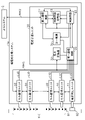
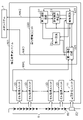
- FIG. 1 is a block diagram showing the overall configuration of an assembled battery management system 1 according to this embodiment.
- FIG. 1 also shows an assembled battery 8 managed by the assembled battery management system 1 and a host system 2 of the assembled battery management system 1 .
- the host system 2 is a system that controls the assembled battery management system 1 .
- the host system 2 is, for example, an ECU (Electric Control Unit) when the assembled battery management system 1 is used as an in-vehicle power source.
- ECU Electronic Control Unit
- the assembled battery management system 1 is a system that manages an assembled battery 8 having a plurality of storage cells 81 connected in series or in parallel.
- the assembled battery management system 1 has, as operation modes, a normal mode and a low power consumption mode in which less power is consumed than in the normal mode.
- the assembled battery management system 1 includes a battery management unit 20, a plurality of cell monitoring units 10, a current measurement unit 11, a first communication network NW1, and a second communication network NW2. .
- the assembled battery 8 has a plurality of power storage cells 81 connected in series.
- a resistance element 82 for current measurement is connected in series to the assembled battery 8 .
- a lithium ion battery can be used as the storage cell 81 .
- a plurality of cell monitoring units 10 are daisy-chained together with the current measurement unit 11 .
- This daisy communication path is the first communication network NW1.
- a first communication network NW1 connects a plurality of cell monitoring units 10 and a battery management unit 20 .
- the second communication network NW2 is a communication network for connecting to the host system 2.
- a communication network based on the CAN (Controller Area Network) standard can be used.
- Each of the plurality of cell monitoring units 10 is a unit that is connected to the plurality of storage cells 81 and measures at least one output voltage of the plurality of storage cells 81 .
- the cell monitoring unit 10 transmits to the first communication circuit 21 of the battery management unit 20 a first operation signal indicating the states of the plurality of storage cells 81 .
- the first operation signal transmitted by the cell monitoring unit 10 is a repeating pulse signal.
- the first motion signal functions as a so-called heartbeat signal.
- the first communication circuit 21 of the battery management unit 20 that has detected the first operation signal can detect that the cell monitoring unit 10 is operating normally.
- the cell monitoring unit 10 detects an abnormality in the storage cell 81 or the like, it transmits a first operation signal indicating the abnormality. Details of the first operation signal will be described later.
- FIG. 2 is a block diagram showing an example of the functional configuration of the cell monitoring unit 10 according to this embodiment.
- the cell monitoring unit 10 includes a pair of daisy communication units 71, a signal generation circuit 72, a control logic circuit 73, a clock oscillator 76, an ADC (Analog-Digital Converter) 77, and a multiplexer. 78.
- the Daisy communication unit 71 is a communication unit that performs Daisy communication.
- Daisy communication unit 71 is connected to first communication network NW1 via an insulating element such as a capacitor or a transformer.
- the signal generation circuit 72 is a circuit that generates the first operation signal.
- the ADC 77 is a circuit that measures the voltage of the storage cell 81.
- the ADC 77 converts the measured voltage value into a digital signal and outputs it to the control logic circuit 73 .
- a multiplexer 78 is a circuit that switches between storage cells 81 measured by the ADC 77 .
- the configuration of the cell monitoring unit 10 is not limited to this.
- the cell monitoring unit 10 may have the same number of ADCs 77 as the plurality of storage cells 81 to be measured.
- the control logic circuit 73 is a circuit that controls the cell monitoring unit 10 .
- the control logic circuit 73 monitors the storage cells 81 based on the measured values input from the ADC 77 and the like.
- the control logic circuit 73 also has an error detector 74 that detects an abnormality in the storage cell 81, for example.
- the control logic circuit 73 causes the signal generation circuit 72 to generate a first operating signal indicative of the detected anomaly.
- the control logic circuit 73 transmits and receives signals via the Daisy communication unit 71 and the first communication network NW1.
- a clock oscillator 76 is an oscillator that outputs a clock signal for operating the control logic circuit 73 .
- the current measurement unit 11 measures the voltage across the resistance element 82 connected in series with the assembled battery 8 .
- the current measurement unit 11 can be implemented by, for example, a configuration similar to that of the cell monitoring unit 10 .
- the battery management unit 20 is a unit that manages the assembled battery 8.
- the battery management unit 20 has a first communication circuit 21 , a second communication circuit 22 , a control circuit 23 , a first power supply 31 , a control circuit power supply 33 , and a power converter 32 .
- the control circuit 23 is a circuit that controls the battery management unit 20 .
- the control circuit 23 can be implemented using, for example, an MCU (Micro-Controller Unit).
- the control circuit 23 controls the first communication circuit 21 and the like in the normal mode, and stops them in the low power consumption mode. Thereby, the power consumption of the assembled battery management system 1 in the low power consumption mode can be suppressed.
- the control circuit power supply 33 is a power supply that supplies power to the control circuit 23 .
- the control circuit power supply 33 also supplies power to the second communication circuit 22 .
- the power supply destination of the control circuit power source 33 is not limited to the control circuit 23 .
- a regulator such as an LDO (Low Drop Out) can be used.
- the control circuit power supply 33 is stopped in the low power consumption mode. Thereby, the power consumption of the assembled battery management system 1 in the low power consumption mode can be suppressed.
- the first power supply 31 is a power supply that supplies power to the first communication circuit 21 .
- a regulator such as an LDO can be used.
- the first communication circuit 21 is a circuit connected to the first communication network NW1.
- the first communication circuit 21 receives first operation signals indicating states of the plurality of storage cells 81 from the plurality of cell monitoring units 10 connected to the first communication network NW1.
- the first communication circuit 21 is controlled by the control circuit 23 in the normal mode.
- the first communication circuit 21 detects the first operating signal from the first communication network NW1 in the low power consumption mode.
- the first communication circuit 21 controls at least one of the stopped control circuit power supply 33, the control circuit 23, and the second communication circuit 22 based on the first operation signal. start one.
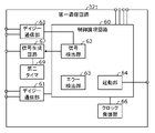
- FIG. 3 is a block diagram showing the functional configuration of the first communication circuit 21 according to this embodiment.
- the first communication circuit 21 has a pair of daisy communication units 61 , a control logic circuit 60 and a clock oscillator 66 .
- the Daisy communication unit 61 is a communication unit that performs Daisy communication.
- Daisy communication unit 61 may be connected to first communication network NW1 via an insulating element such as a capacitor or a transformer.
- the control logic circuit 60 is a circuit that controls the first communication circuit 21 .
- the control logic circuit 60 detects signals from the plurality of cell monitoring units 10 and current measurement units 11 input from the daisy communication section 61 and controls the first communication circuit 21 .
- the control logic circuit 60 has, for example, a signal detector 62 , an error detector 63 and an activation part 64 .
- the signal detection unit 62 detects signals from the first communication network NW1.
- the signal detector 62 detects, for example, the first operating signal from the cell monitoring unit 10 .
- the error detection unit 63 detects an abnormality in the storage cell 81 or the like based on the signal detected by the signal detection unit 62 .
- the activation unit 64 activates the first communication circuit 21 based on an activation signal from the outside.
- a clock oscillator 66 is an oscillator that outputs a clock signal for operating the control logic circuit 60 .
- the second communication circuit 22 is a circuit connected to the second communication network NW2 for connecting to the host system 2 of the assembled battery management system 1.
- the second communication circuit 22 includes, for example, a CAN interface.
- the second communication circuit 22 is supplied with power from the control circuit power source 33 .
- the second communication circuit 22 is also supplied with power from a power supply other than the control circuit power supply 33, and can be activated and operated even when the control circuit power supply 33 is stopped.
- the power converter 32 is a converter that supplies power to the first communication circuit 21 .
- the power converter 32 converts signals communicated in the first communication network NW1 into DC power and supplies the DC power to the first communication circuit 21 .
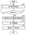
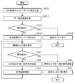
- FIG. 4 is a flow chart showing the operation when switching from the normal mode to the low power consumption mode in the assembled battery management system 1 according to the present embodiment.
- FIG. 5 is a flow chart showing the operation in the low power consumption mode of the first communication circuit 21 according to this embodiment.
- the first communication circuit 21 of the battery management unit 20 before switching from the normal mode to the low power consumption mode, the first communication circuit 21 of the battery management unit 20 first sends a command signal (that is, , communication command) (S10).
- a command signal that is, , communication command
- the measurement period is longer than the measurement period in the normal mode. That is, in the low power consumption mode, the cell monitoring unit 10 performs intermittent measurement.
- a command signal instructing switching to the low power consumption mode is sent from the host system 2 to the second communication circuit 22 via the second communication network NW2. It is initiated based on being sent.
- the control circuit 23 switches the operation mode of the assembled battery management system 1 to the low power consumption mode (S12). Specifically, the control circuit 23 stops the second communication circuit 22 . The control circuit 23 transmits a stop signal to the second communication circuit 22 to stop the second communication circuit 22 . Further, the control circuit 23 stops itself by stopping the control circuit power supply 33 that supplies power to the control circuit 23 . In this way, in the low power consumption mode, not only is the cell monitoring unit 10 intermittently measured, but also the control circuit 23, the control circuit power supply 33, and the second communication circuit 22 are stopped. power consumption can be reduced.
- the state of the first communication circuit 21 may be diagnosed before the control circuit 23 is stopped as described above.
- the first communication circuit 21 substantially controls the assembled battery management system 1 in the low power consumption mode. Therefore, if the operation mode is switched to the low power consumption mode when there is an abnormality in the first communication circuit 21, a serious problem such as being unable to detect an abnormality in the assembled battery management system 1 may occur. Therefore, by diagnosing the first communication circuit 21 before the control circuit 23 stops, it is possible to reduce the occurrence of problems in the assembled battery management system 1 in the low power consumption mode.
- the first communication circuit 21 outputs a control activation signal for activating the control circuit 23 to the control circuit 23 .
- the control circuit 23 diagnoses the state of the first communication circuit 21 based on the control activation signal. That is, it is diagnosed whether or not the output control activation signal can activate the control circuit 23 .
- the first communication circuit 21 uses the first operation signal from the cell monitoring unit 10 to monitor the storage cell 81 and the cell. Monitor the status of the unit 10; Since the operation of the first communication circuit 21 in the low power consumption mode is restricted, the power supplied from the first power supply 31 can be suppressed.
- the battery management unit 20 also has a function of stopping the first power supply 31 in the low power consumption mode.
- the control circuit 23 stops the first power supply 31 .
- the first power supply 31 converts signals communicated in the first communication network NW1 into DC power and supplies the DC power to the first communication circuit 21 .
- power converter 32 converts the first operating signal to DC power.
- the cell monitoring unit 10 measures the voltage of the storage cell 81 (S14).
- the cell monitoring unit 10 determines whether or not an abnormality in the storage cell 81 or the like is detected based on the measurement results (S16).
- the cell monitoring unit 10 does not detect any abnormality (No in S16)
- the cell monitoring unit 10 transmits a first operation signal indicating normality to the first communication network NW1 (S18).
- the cell monitoring unit 10 transmits a first operation signal indicating the abnormality to the first communication network NW1 (S20). That is, when at least one of the control circuit power supply 33, the control circuit 23, and the second communication circuit 22 is stopped and the cell monitoring unit 10 detects an abnormality, the cell monitoring unit 10 indicates an abnormality. Output a first operating signal.
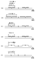
- FIG. 6 is a graph showing an example of temporal waveforms of the first operating signal indicating normality and the first operating signal indicating abnormality according to the present embodiment.
- Graph (a) of FIG. 6 shows an example of the first operating signal indicating normality
- graphs (b) to (f) each show an example of the first operating signal indicating abnormality.
- the first operating signal indicating abnormality corresponds to the first operating signal indicating normality.
- the abnormal first operating signal may have a different number of pulses (m) than the normal operating frequency, as shown in graph (b).
- the frequency (t) of the abnormal first operating signal may differ from the normal first operating frequency.
- the duty (b) of the first operating signal indicating abnormality may be different from that of the first operating frequency indicating normality.
- the first operating signal indicating abnormality may be a signal that is fixed at the H level for a predetermined period of time.
- the first operating signal indicating abnormality may be a signal fixed at L level for a predetermined period. In other words, no signal need be output.
- a mode in which no signal is output is also included as an example of the first operation signal indicating abnormality.
- step S18 when the cell monitoring unit 10 outputs the first operation signal indicating normality, the cell monitoring unit 10 waits for a predetermined period (S22). That is, the cell monitoring unit 10 waits for a predetermined period of time without measuring the voltage of the storage cell 81 .
- the cell monitoring unit 10 returns to step S14 after waiting for a predetermined period.
- step S20 when the cell monitoring unit 10 outputs the first operation signal indicating abnormality, the assembled battery management system 1 is switched to the normal mode (S24). This terminates the low power consumption mode.
- the first communication circuit 21 detects the first operation signal from the first communication network NW1 (S30).
- the first communication circuit 21 determines whether or not an abnormality has been detected based on the first operation signal (S32). Specifically, the first communication circuit 21 determines whether the first operation signal is a signal indicating abnormality as shown in FIG. If the first communication circuit 21 does not detect an abnormality (No in S32), the process returns to step S30. On the other hand, when the first communication circuit 21 detects an abnormality (Yes in S32), the first communication circuit 21 activates the control circuit 23 or the control circuit power supply 33 (S34). For example, the first communication circuit 21 activates the control circuit power supply 33 by transmitting an activation signal to the control circuit power supply 33 (S36).
- the control circuit power source 33 starts to supply power to the control circuit 23, and the control circuit 23 is activated. It should be noted that activating the control circuit 23 by activating the control circuit power source 33 in this way is also simply referred to as activating the control circuit 23 .
- the first communication circuit 21 may also activate the second communication circuit 22, or the activated control circuit 23 may activate the second communication circuit 22 at the same time. Further, in the present embodiment, the first communication circuit 21 may activate the first power supply 31 and stop the power converter 32 from outputting DC power. As a result, in the first communication circuit 21, the restriction on the operation in accordance with the DC power of the power converter 32 is lifted.
- the first communication circuit 21 may activate the second communication circuit 22 that is stopped in the low power consumption mode.
- the second communication circuit 22 notifies the host system 2 of activation of the second communication circuit 22 via the second communication network NW2.
- the host system 2 that has received the notification may activate the control circuit power supply 33 and the control circuit 23 via the second communication network NW2.
- the control circuit power supply 33 may be activated by the host system 2 .
- the operation mode of the assembled battery management system 1 is switched to the normal mode (S38). Specifically, the first communication circuit 21 transmits command signals to the cell monitoring unit 10 (and the current measurement unit 11). This switches the operation mode of the cell monitoring unit 10 to the normal mode.
- the operation mode can be switched.
- the control circuit 23, the control circuit power supply 33, the first power supply 31, and the second communication circuit 22 are stopped in the low power consumption mode, so power consumption can be suppressed.
- the storage cell 81 can be reliably monitored, and when an abnormality is detected, the first communication circuit 21 can quickly switch to the normal mode.
- FIG. 7 is a block diagram showing the overall configuration of an assembled battery management system 1a according to a modification of the present embodiment.
- the assembled battery management system 1a includes an individual communication line L10 that directly connects each of the cell monitoring units 10 and the first communication circuit 21, a current measurement unit 11, and an individual communication line L11 directly connected to the first communication circuit 21 .
- the first communication circuit 21 may detect a signal indicating abnormality from these individual communication lines L10 and L11.
- Embodiment 2 An assembled battery management system according to Embodiment 2 will be described.
- the assembled battery management system according to the present embodiment differs from the assembled battery management system 1 according to Embodiment 1 mainly in that the first communication circuit includes a third communication network for connecting to the host system. .
- the assembled battery management system according to the present embodiment will be described, focusing on differences from the assembled battery management system 1 according to the first embodiment.
- FIG. 8 is a block diagram showing the overall configuration of the assembled battery management system 101 according to this embodiment.
- the assembled battery management system 101 includes a battery management unit 120, a plurality of cell monitoring units 10, a current measurement unit 11, a first communication network NW1, a second communication network NW2, a second and three communication networks NW3.
- the third communication network NW3 is a communication network for connecting to the host system 2.
- the battery management unit 120 has a first communication circuit 121, a second communication circuit 22, a control circuit 23, a first power supply 31, and a power supply 33 for control circuit.
- the first communication circuit 121 is connected to the third communication network NW3 for connecting to the host system 2. Also, when the control circuit 23 or the second communication circuit 22 cannot communicate, the first communication circuit 121 communicates with the host system 2 via the third communication network NW3.
- FIG. 9 is a block diagram showing the functional configuration of the first communication circuit 121 according to this embodiment.
- the first communication circuit 121 has a pair of daisy communication units 61 , a control logic circuit 60 , a clock oscillator 66 and a signal generation circuit 67 .
- the signal generation circuit 67 is a circuit that generates the second operation signal.
- the signal generation circuit 67 generates a second operation signal based on the first operation signal detected by the signal detection unit 62 of the control logic circuit 60, and transmits the second operation signal to the third communication network NW3.
- the cell monitoring unit 10 when at least one of the control circuit power supply 33, the control circuit 23, and the second communication circuit 22 is stopped (that is, in the low power consumption mode) , the cell monitoring unit 10 sends a first operating signal to the first communication circuit 121 .
- the first communication circuit 121 transmits a second operation signal indicating that the cell monitoring unit 10 and the first communication circuit 121 are operating through the third communication network NW3.
- the second operating signal is a signal containing the same information as the first operating signal.
- the aspect of the second operation signal, such as the time waveform, is not particularly limited.
- the second operating signal may be a signal similar to the first operating signal.
- the cell monitoring unit 10 detects an abnormality. If so, the cell monitoring unit 10 outputs a first operating signal indicating an abnormality.
- the first communication circuit 121 receives a first operation signal indicating abnormality from the first communication network NW1, the first communication circuit 121 outputs a second operation signal indicating abnormality.
- the first communication circuit 121 may stop transmitting the second operation signal when an abnormality occurs in the first communication circuit 121 .
- the host system 2 can detect that at least one of the first operation signal and the first communication circuit 121 is abnormal.
- the control circuit 23 or the second communication circuit 22 is activated via the second communication network NW2. Thereby, the control circuit 23 can appropriately respond to the abnormality.
- FIG. 10 is a flow chart showing operations in the low power consumption mode of the first communication circuit 121 and the host system 2 according to this embodiment.
- the assembly according to the first embodiment is performed.
- the operation is the same as that of the battery management system 1 . Therefore, the operation after the step in which the first communication circuit 121 detects the first operation signal will be described below.
- communication between the first communication circuit 121 and the host system 2 via the third communication network NW3 is started.
- the first communication circuit 121 detects the first operation signal from the first communication network NW1 (S130).
- the first communication circuit 121 determines whether or not an abnormality has been detected based on the first operation signal (S132). When the first communication circuit 121 does not detect an abnormality (No in S132), the first communication circuit 121 transmits a second operation signal indicating normality to the host system 2 via the third communication network NW3 ( S134) and returns to step S130.
- the first communication circuit 121 detects an abnormality (Yes in S132), the first communication circuit 121 transmits a second operation signal indicating the abnormality to the host system 2 via the third communication network NW3 ( S136).
- the host system 2 that receives the second operation signal causes the second communication circuit 22 to activate the control circuit 23 or the control circuit power supply 33 via the second communication network NW2 (S138).
- the operating mode of the assembled battery management system 101 is switched to the normal mode (S140). Specifically, the first communication circuit 121 transmits command signals to the cell monitoring unit 10 (and the current measurement unit 11). This switches the operation mode of the cell monitoring unit 10 to the normal mode.
- the operation mode can be switched in the assembled battery management system 101 .
- the control circuit 23, the control circuit power supply 33, and the second communication circuit 22 are stopped in the low power consumption mode, so power consumption can be suppressed.
- the storage cell 81 can be reliably monitored, and when an abnormality is detected, the first communication circuit 121 can quickly switch to the normal mode.
- Embodiment 3 An assembled battery management system according to Embodiment 3 will be described.
- the assembled battery management system according to the present embodiment is mainly different from the assembled battery according to the second embodiment in that the first communication circuit transmits the second operation signal not only to the host system 2 but also to the control circuit 23 . It differs from the management system 101 .
- the assembled battery management system according to the present embodiment will be described, focusing on differences from the assembled battery management system 101 according to the second embodiment.
- FIG. 11 is a block diagram showing the overall configuration of an assembled battery management system 201 according to this embodiment.
- the assembled battery management system 201 includes a battery management unit 220, a plurality of cell monitoring units 10, a current measurement unit 11, a first communication network NW1, a second communication network NW2, a second and three communication networks NW3.
- the battery management unit 220 has a first communication circuit 121, a second communication circuit 22, a control circuit 223, a first power supply 31, and a control circuit power supply 33.
- the control circuit 223 receives the second operation signal from the first communication circuit 121 via the third communication network NW3.
- the control circuit 223 diagnoses the state of the first communication circuit 121 based on the second operation signal before stopping.
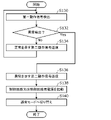
- FIG. 12 is a flow chart showing the operation of switching from the normal mode to the low power consumption mode in the assembled battery management system 201 according to the present embodiment.
- the first communication circuit of the battery management unit 220 is switched to the first communication circuit as in the operation of the assembled battery management system 1 according to the first embodiment.
- 121 transmits a command signal to the cell monitoring unit 10 (and the current measurement unit 11) (S210).
- the first communication circuit 121 is diagnosed (S212), and it is determined whether or not an abnormality is detected in the first communication circuit 121 (S214). Specifically, before the control circuit 223 stops, the first communication circuit 121 outputs the second operation signal to the control circuit 223 or the host system 2 via the third communication network NW3. The control circuit 223 or the host system 2 diagnoses the state of the first communication circuit 121 based on the second operating signal. As a result of the diagnosis, if no abnormality is detected in the first communication circuit 121 (No in S214), the assembled battery management system 201 switches the operation mode to the low power consumption mode (S216).
- the assembled battery management system 201 returns the operating mode to the normal mode (S218). Specifically, the control circuit 223 returns to the normal mode state by transmitting a command signal to the cell monitoring unit 10 or the like.
- the assembled battery management system 201 When the operation mode of the assembled battery management system 201 is switched to the low power consumption mode, the assembled battery management system 201 performs the same operations as steps S14 to S24 of the assembled battery management system 1 according to the first embodiment. Also, the operation of switching the assembled battery management system 201 from the low power consumption mode to the normal mode is the same as the operation of the assembled battery management system 101 according to the second embodiment.
- the assembled battery management system 201 according to the present embodiment also has the same effects as the assembled battery management system 101 according to the second embodiment.
- Embodiment 4 An assembled battery management system according to Embodiment 4 will be described.
- the assembled battery management system according to the present embodiment differs from the assembled battery management system 201 according to Embodiment 3 mainly in that the first communication circuit or the like changes the mode of the signal generated based on the timer. do.
- the assembled battery management system according to the present embodiment will be described, focusing on differences from the assembled battery management system 201 according to the third embodiment.
- FIG. 13 is a block diagram showing the overall configuration of an assembled battery management system 301 according to this embodiment.
- the assembled battery management system 301 includes a battery management unit 320, a plurality of cell monitoring units 310, a current measurement unit 311, a first communication network NW1, a second communication network NW2, a and three communication networks NW3.
- the battery management unit 320 has a first communication circuit 321, a second communication circuit 22, a control circuit 223, a first power supply 31, and a control circuit power supply 33.
- FIG. 14 is a block diagram showing an example of the functional configuration of cell monitoring unit 310 according to this embodiment.
- the cell monitoring unit 310 includes a pair of daisy communication units 71, a signal generation circuit 72, a control logic circuit 73, a clock oscillator 76, an ADC 77, a multiplexer 78, and a first timer 79. , and a power supply control circuit 80 .
- the power supply control circuit 80 is a circuit that controls power supply from the power supply of the cell monitoring unit 310 .
- the first timer 79 is a circuit that measures time, and causes the power supply control circuit 80 to stop supplying power to the cell monitoring unit 310 when it detects that a preset first time has elapsed. That is, the first timer 79 stops the operation of the cell monitoring unit 310 when it detects that the preset first time has elapsed.
- the current measurement unit 311 also has the same configuration as the cell monitoring unit 310.
- FIG. 15 is a block diagram showing the functional configuration of the first communication circuit 321 according to this embodiment.
- the first communication circuit 321 has a pair of daisy communication units 61, a control logic circuit 60, a clock oscillator 66, a signal generation circuit 67 and a second timer 69.
- the second timer 69 is a circuit that measures time, and causes the signal generation circuit 67 to stop generating the second operation signal when it detects that a preset second time has elapsed.
- the power control circuit 80 to stop supplying power to the cell monitoring unit 310 . That is, the first timer 79 stops the operation of the cell monitoring unit 310 when it detects that the preset first time has elapsed. Along with this, the output of the first operation signal is stopped. Therefore, the first communication circuit 321 detects the stop of the first operation signal and activates the control circuit power supply 33 or the control circuit 223 . Thereby, the assembled battery management system 301 is switched to the normal mode.
- the first communication circuit 321 has a second timer 69, and the second timer 69 outputs a second operation signal when it detects that a preset second time has elapsed.
- stop the output of The host system 2 that has detected the stop of the second operation signal activates the control circuit power supply 33 , the control circuit 223 , or the second communication circuit 22 . That is, the second timer 69 activates the control circuit power supply 33, the control circuit 223, or the second communication circuit 22 when detecting that the preset second time has elapsed. In other words, switch to normal mode.
- an abnormality in the measurement result determination circuit of the cell monitoring unit 310 that cannot be detected by intermittent measurement in the low power consumption mode, or an error in the measurement result. Failures such as sticking can be detected without delay.
- the first timer 79 stops the operation of the cell monitoring unit 310, but the configuration of the first timer 79 is not limited to this.
- the first timer 79 may cause the signal generation circuit 72 to stop outputting the first operation signal when detecting that the first time has elapsed.
- the first timer 79 may cause the signal generation circuit 72 of the cell monitoring unit 310 to output a first operation signal indicating an abnormality when detecting that a preset first time has elapsed.
- the second timer 69 stops the output of the second operation signal in the signal generating circuit 67, but the configuration of the second timer 69 is not limited to this.
- the second timer 69 may cause the signal generation circuit 67 to output a second operation signal indicating an abnormality when detecting that the second time has elapsed.
- the assembled battery 8 was not included as a component of the assembled battery management system, but the assembled battery 8 may be included as a component of the assembled battery management system.
- control circuit power supply, the control circuit, and the second communication circuit are stopped in the low power consumption mode, but they do not necessarily have to be stopped.
- the control circuit and the second communication circuit may be stopped and the power supply for the control circuit may be started.
- the power supply for the control circuit and the control circuit may be stopped, and the second communication circuit may be started. At least one of the power supply for the control circuit, the control circuit, and the second communication circuit should be stopped in the low power consumption mode.
- the battery management unit 20 has the power converter 32 in the first embodiment, it does not necessarily have to have it.
- the battery management units 120, 220, and 320 do not have the power converter 32 in Embodiments 2 to 4 above, they may have them.
- the cell monitoring unit may output first operation information indicating not only voltage abnormality but also temperature abnormality, clock abnormality, and the like.
- the assembled battery management system according to each of the above embodiments may be housed in one housing, or may be separated into a plurality of units, for example.
- a system LSI is an ultra-multifunctional LSI manufactured by integrating multiple components on a single chip. Specifically, it is a computer system that includes a microprocessor, ROM, RAM, etc. . A computer program is stored in the RAM. The system LSI achieves its functions by the microprocessor operating according to the computer program.
- IC card or module is a computer system composed of a microprocessor, ROM, RAM and the like.
- the IC card or module may include the super multifunctional LSI.
- the IC card or module achieves its function by the microprocessor operating according to the computer program. This IC card or this module may have tamper resistance.
- the present disclosure may be a computer system comprising a microprocessor and memory, the memory storing the computer program, and the microprocessor operating according to the computer program.
- the individual communication line of the assembled battery management system 1a according to the first embodiment may be applied to the assembled battery management system according to another embodiment.
- the assembled battery management system according to the present disclosure can be used, for example, as an assembled battery management system for an in-vehicle assembled battery system.
Abstract
Description
実施の形態1に係る組電池管理システムについて説明する。 (Embodiment 1)
An assembled battery management system according to Embodiment 1 will be described.
本実施の形態に係る組電池管理システムの全体構成について図1を用いて説明する。図1は、本実施の形態に係る組電池管理システム1の全体構成を示すブロック図である。図1には、組電池管理システム1によって、管理される組電池8、及び、組電池管理システム1の上位システム2も併せて示されている。 [1-1. overall structure]
The overall configuration of the assembled battery management system according to this embodiment will be described with reference to FIG. FIG. 1 is a block diagram showing the overall configuration of an assembled battery management system 1 according to this embodiment. FIG. 1 also shows an assembled
本実施の形態に係る組電池管理システム1の動作について、図4を用いて説明する。図4は、本実施の形態に係る組電池管理システム1における通常モードから低消費電力モードへ切り替える場合の動作を示すフローチャートである。図5は、本実施の形態に係る第一通信回路21の低消費電力モードにおける動作を示すフローチャートである。 [1-2. motion]
The operation of the assembled battery management system 1 according to this embodiment will be described with reference to FIG. FIG. 4 is a flow chart showing the operation when switching from the normal mode to the low power consumption mode in the assembled battery management system 1 according to the present embodiment. FIG. 5 is a flow chart showing the operation in the low power consumption mode of the
本実施の形態に係る組電池管理システム1の変形例について図7を用いて説明する。図7は、本実施の形態の変形例に係る組電池管理システム1aの全体構成を示すブロック図である。 [1-3. Modification]
A modification of the assembled battery management system 1 according to the present embodiment will be described with reference to FIG. FIG. 7 is a block diagram showing the overall configuration of an assembled battery management system 1a according to a modification of the present embodiment.
実施の形態2に係る組電池管理システムについて説明する。本実施の形態に係る組電池管理システムは、主に、第一通信回路が上位システムに接続するための第三通信ネットワークを備える点において、実施の形態1に係る組電池管理システム1と相違する。以下、本実施の形態に係る組電池管理システムについて、実施の形態1に係る組電池管理システム1との相違点を中心に説明する。 (Embodiment 2)
An assembled battery management system according to
本実施の形態に係る組電池管理システムの全体構成について図8を用いて説明する。図8は、本実施の形態に係る組電池管理システム101の全体構成を示すブロック図である。図8に示されるように、組電池管理システム101は、電池管理ユニット120と、複数のセル監視ユニット10と、電流測定ユニット11と、第一通信ネットワークNW1と、第二通信ネットワークNW2と、第三通信ネットワークNW3とを備える。 [2-1. overall structure]
The overall configuration of the assembled battery management system according to this embodiment will be described with reference to FIG. FIG. 8 is a block diagram showing the overall configuration of the assembled
本実施の形態に係る組電池管理システム101の動作について、図10を用いて説明する。図10は、本実施の形態に係る第一通信回路121及び上位システム2の低消費電力モードにおける動作を示すフローチャートである。 [2-2. motion]
Operation of the assembled
実施の形態3に係る組電池管理システムについて説明する。本実施の形態に係る組電池管理システムは、主に、第一通信回路が第二動作信号を上位システム2だけでなく、制御回路23へも送信する点において、実施の形態2に係る組電池管理システム101と相違する。以下、本実施の形態に係る組電池管理システムについて、実施の形態2に係る組電池管理システム101との相違点を中心に説明する。 (Embodiment 3)
An assembled battery management system according to Embodiment 3 will be described. The assembled battery management system according to the present embodiment is mainly different from the assembled battery according to the second embodiment in that the first communication circuit transmits the second operation signal not only to the
本実施の形態に係る組電池管理システムの全体構成について図11を用いて説明する。図11は、本実施の形態に係る組電池管理システム201の全体構成を示すブロック図である。図11に示されるように、組電池管理システム201は、電池管理ユニット220と、複数のセル監視ユニット10と、電流測定ユニット11と、第一通信ネットワークNW1と、第二通信ネットワークNW2と、第三通信ネットワークNW3とを備える。 [3-1. overall structure]
The overall configuration of the assembled battery management system according to this embodiment will be described with reference to FIG. 11 . FIG. 11 is a block diagram showing the overall configuration of an assembled
本実施の形態に係る組電池管理システム201の動作について、図12を用いて説明する。図12は、本実施の形態に係る組電池管理システム201における通常モードから低消費電力モードへ切り替える場合の動作を示すフローチャートである。 [3-2. motion]
The operation of the assembled
実施の形態4に係る組電池管理システムについて説明する。本実施の形態に係る組電池管理システムは、主に、第一通信回路などが、タイマに基づいて生成する信号の態様を変化させる点において、実施の形態3に係る組電池管理システム201と相違する。以下、本実施の形態に係る組電池管理システムについて、実施の形態3に係る組電池管理システム201との相違点を中心に説明する。 (Embodiment 4)
An assembled battery management system according to Embodiment 4 will be described. The assembled battery management system according to the present embodiment differs from the assembled
本実施の形態に係る組電池管理システムの全体構成について図13を用いて説明する。図13は、本実施の形態に係る組電池管理システム301の全体構成を示すブロック図である。図13に示されるように、組電池管理システム301は、電池管理ユニット320と、複数のセル監視ユニット310と、電流測定ユニット311と、第一通信ネットワークNW1と、第二通信ネットワークNW2と、第三通信ネットワークNW3とを備える。 [4-1. overall structure]
The overall configuration of the assembled battery management system according to this embodiment will be described with reference to FIG. 13 . FIG. 13 is a block diagram showing the overall configuration of an assembled
本実施の形態に係る組電池管理システム301のセル監視ユニット310の第一タイマ79は、上述したように、低消費電力モードにおいて、第一時間が経過したことを検出した場合に、電源制御回路80にセル監視ユニット310への電力の供給を停止させる。つまり、第一タイマ79は、予め設定された第一時間が経過したことを検出した場合に、セル監視ユニット310の動作を停止させる。これに伴い、第一動作信号の出力が停止される。このため、第一通信回路321は、第一動作信号の停止を検出し、制御回路用電源33、又は制御回路223を起動させる。これにより、組電池管理システム301は、通常モードに切り替えられる。 [4-2. motion]
When the
以上、本開示について、各実施の形態に基づいて説明したが、本開示は、上記各実施の形態に限定されるものではない。 (Modified example, etc.)
As described above, the present disclosure has been described based on each embodiment, but the present disclosure is not limited to each of the above embodiments.
2 上位システム
8 組電池
10、310 セル監視ユニット
11、311 電流測定ユニット
20、120、220、320 電池管理ユニット
21、121、321 第一通信回路
22 第二通信回路
23、223 制御回路
31 第一電源
32 電力変換器
33 制御回路用電源
60、73 制御論理回路
61、71 デイジー通信部
62 信号検出部
63、74 エラー検出部
64 起動部
66、76 クロック発振器
67、72 信号生成回路
69 第二タイマ
77 ADC
78 マルチプレクサ
79 第一タイマ
80 電源制御回路
81 蓄電セル
82 抵抗素子
L10、L11 個別通信線
NW1 第一通信ネットワーク
NW2 第二通信ネットワーク
NW3 第三通信ネットワーク 1, 1a, 101, 201, 301 assembled
78
Claims (22)
- 直列又は並列に接続される複数の蓄電セルを有する組電池を管理する組電池管理システムであって、
前記複数の蓄電セルに接続され、前記複数の蓄電セルの少なくとも一つの出力電圧を測定するセル監視ユニットと、
前記組電池を管理する電池管理ユニットと、
前記セル監視ユニットと前記電池管理ユニットとを接続する第一通信ネットワークとを備え、
前記電池管理ユニットは、
前記第一通信ネットワークに接続される第一通信回路と、
前記組電池管理システムの上位システムに接続するための第二通信ネットワークに接続される第二通信回路と、
前記電池管理ユニットを制御する制御回路と、
前記制御回路に電力を供給する制御回路用電源とを有し、
前記組電池管理システムは、動作モードとして、通常モードと、通常モードより消費電力が少ない低消費電力モードとを有し、
前記低消費電力モードにおいて、前記制御回路用電源、前記制御回路、及び前記第二通信回路の少なくとも一つは、停止しており、
前記第一通信回路は、前記低消費電力モードから前記通常モードへの移行時に、前記制御回路用電源、前記制御回路、及び前記第二通信回路の少なくとも一つを起動させる
組電池管理システム。 An assembled battery management system for managing an assembled battery having a plurality of storage cells connected in series or in parallel,
a cell monitoring unit connected to the plurality of storage cells and measuring at least one output voltage of the plurality of storage cells;
a battery management unit that manages the assembled battery;
a first communication network connecting the cell monitoring unit and the battery management unit;
The battery management unit
a first communication circuit connected to the first communication network;
a second communication circuit connected to a second communication network for connecting to a host system of the assembled battery management system;
a control circuit that controls the battery management unit;
a control circuit power source that supplies power to the control circuit;
The assembled battery management system has, as operation modes, a normal mode and a low power consumption mode that consumes less power than the normal mode,
in the low power consumption mode, at least one of the control circuit power supply, the control circuit, and the second communication circuit is stopped;
The assembled battery management system, wherein the first communication circuit activates at least one of the control circuit power source, the control circuit, and the second communication circuit when transitioning from the low power consumption mode to the normal mode. - 前記セル監視ユニットは、前記第一通信回路へ前記複数の蓄電セルの状態を示す第一動作信号を出力し、
前記セル監視ユニットは、前記制御回路用電源、前記制御回路、及び前記第二通信回路の少なくとも一つが停止しており、かつ、異常を検出した場合に、異常を示す前記第一動作信号を出力し、
前記第一通信回路は、異常を示す前記第一動作信号を受信した場合に、前記制御回路用電源、前記制御回路、及び前記第二通信回路を起動させる
請求項1に記載の組電池管理システム。 The cell monitoring unit outputs a first operation signal indicating the states of the plurality of storage cells to the first communication circuit,
The cell monitoring unit outputs the first operation signal indicating an abnormality when at least one of the control circuit power supply, the control circuit, and the second communication circuit is stopped and an abnormality is detected. death,
The assembled battery management system according to claim 1, wherein the first communication circuit activates the control circuit power source, the control circuit, and the second communication circuit when receiving the first operation signal indicating an abnormality. . - 前記制御回路用電源は、前記第一通信回路、又は、前記上位システムによって起動される
請求項1に記載の組電池管理システム。 The assembled battery management system according to claim 1, wherein the control circuit power supply is activated by the first communication circuit or the host system. - 前記低消費電力モードにおいて、前記第二通信回路は停止しており、
前記第二通信回路は、前記第一通信回路によって起動される場合に、前記第二通信ネットワークを介して前記上位システムに第一通信回路の起動を通知し、
前記上位システムは、前記第二通信ネットワークを介して前記制御回路用電源、及び前記制御回路の少なくとも一方を起動する
請求項3に記載の組電池管理システム。 In the low power consumption mode, the second communication circuit is stopped,
the second communication circuit, when activated by the first communication circuit, notifies the host system of activation of the first communication circuit via the second communication network;
The assembled battery management system according to claim 3, wherein the host system activates at least one of the control circuit power supply and the control circuit via the second communication network. - 前記制御回路、又は前記第二通信回路が停止している場合に、前記セル監視ユニットが送信する前記第一動作信号は、繰り返しパルス信号である
請求項2に記載の組電池管理システム。 The assembled battery management system according to claim 2, wherein the first operation signal transmitted by the cell monitoring unit is a repeated pulse signal when the control circuit or the second communication circuit is stopped. - 前記電池管理ユニットは、前記第一通信回路に電力を供給する、第一電源、及び電力変換器を有し、
前記電池管理ユニットは、前記低消費電力モードにおいて、前記第一電源を停止する機能を有し、
前記第一電源を停止している場合に、前記電力変換器は、前記第一通信ネットワークにおいて通信される信号を直流電力に変換し、前記第一通信回路に前記直流電力を供給する
請求項2又は5に記載の組電池管理システム。 the battery management unit has a first power source and a power converter for powering the first communication circuit;
The battery management unit has a function of stopping the first power supply in the low power consumption mode,
2. The power converter converts a signal communicated in the first communication network into DC power and supplies the DC power to the first communication circuit when the first power supply is stopped. Or the assembled battery management system according to 5. - 前記第一電源が停止しており、かつ、前記セル監視ユニットが異常を検出した場合に、前記セル監視ユニットは、異常を示す前記第一動作信号を出力し、
前記第一通信回路は,異常を示す前記第一動作信号を前記第一通信ネットワークを介して受信した場合に、前記第一電源を起動させ、かつ、前記電力変換器の前記直流電力の出力を停止する
請求項6に記載の組電池管理システム。 when the first power supply is stopped and the cell monitoring unit detects an abnormality, the cell monitoring unit outputs the first operation signal indicating the abnormality;
The first communication circuit activates the first power supply and reduces the output of the DC power from the power converter when the first operation signal indicating an abnormality is received via the first communication network. The assembled battery management system according to claim 6, which stops. - 直列又は並列に接続される複数の蓄電セルを有する組電池を管理する組電池管理システムであって、
前記複数の蓄電セルに接続され、前記複数の蓄電セルの少なくとも一つの出力電圧を測定するセル監視ユニットと、
前記組電池を管理する電池管理ユニットと、
前記セル監視ユニットと前記電池管理ユニットとを接続する第一通信ネットワークとを備え、
前記電池管理ユニットは、
前記第一通信ネットワークに接続される第一通信回路と、
前記組電池管理システムの上位システムに接続するための第二通信ネットワークに接続される第二通信回路と、
前記電池管理ユニットを制御する制御回路とを有し、
前記第一通信回路は、前記上位システムに接続するための第三通信ネットワークに接続される
組電池管理システム。 An assembled battery management system for managing an assembled battery having a plurality of storage cells connected in series or in parallel,
a cell monitoring unit connected to the plurality of storage cells and measuring at least one output voltage of the plurality of storage cells;
a battery management unit that manages the assembled battery;
a first communication network connecting the cell monitoring unit and the battery management unit;
The battery management unit
a first communication circuit connected to the first communication network;
a second communication circuit connected to a second communication network for connecting to a host system of the assembled battery management system;
a control circuit that controls the battery management unit;
The assembled battery management system, wherein the first communication circuit is connected to a third communication network for connecting to the host system. - 前記制御回路、及び前記第二通信回路の少なくとも一方が通信できない場合に、前記第一通信回路は、前記第三通信ネットワークにより前記上位システムと通信する
請求項8に記載の組電池管理システム。 The assembled battery management system according to claim 8, wherein when at least one of the control circuit and the second communication circuit cannot communicate, the first communication circuit communicates with the host system through the third communication network. - 前記制御回路、及び前記第二通信回路の少なくとも一方が停止している場合に、前記セル監視ユニットは、第一動作信号を、前記第一通信回路に送信し、
前記第一通信回路は、前記第三通信ネットワークにより前記セル監視ユニット、及び前記第一通信回路が動作中であることを示す第二動作信号を送信する
請求項8又は9に記載の組電池管理システム。 when at least one of the control circuit and the second communication circuit is stopped, the cell monitoring unit transmits a first operation signal to the first communication circuit;
10. The assembled battery management according to claim 8, wherein the first communication circuit transmits a second operation signal indicating that the cell monitoring unit and the first communication circuit are operating through the third communication network. system. - 前記制御回路、及び前記第二通信回路の少なくとも一方が停止している場合に送信される前記第一動作信号、及び前記第二動作信号は、繰り返しパルス信号である
請求項10に記載の組電池管理システム。 The assembled battery according to claim 10, wherein the first operation signal and the second operation signal that are transmitted when at least one of the control circuit and the second communication circuit is stopped are repeated pulse signals. management system. - 前記制御回路、又は前記第二通信回路が停止しており、かつ、前記セル監視ユニットが異常を検出した場合に、前記セル監視ユニットは、異常を示す前記第一動作信号を出力し、
前記第一通信回路は、異常を示す前記第一動作信号を前記第一通信ネットワークより受信した場合に、前記第一通信回路は、異常を示す前記第二動作信号を出力する
請求項10又は11に記載の組電池管理システム。 when the control circuit or the second communication circuit is stopped and the cell monitoring unit detects an abnormality, the cell monitoring unit outputs the first operation signal indicating the abnormality;
12. When said first communication circuit receives said first operation signal indicating abnormality from said first communication network, said first communication circuit outputs said second operation signal indicating abnormality. The assembled battery management system described in . - 前記第一通信回路が、異常を示す前記第二動作信号を出力した場合、前記上位システムは、前記制御回路、又は前記第二通信回路を起動させる
請求項10~12のいずれか1項に記載の組電池管理システム。 The host system according to any one of claims 10 to 12, wherein when the first communication circuit outputs the second operation signal indicating an abnormality, the host system activates the control circuit or the second communication circuit. battery management system. - 前記制御回路は、停止する前に、前記第一通信回路の状態を診断する
請求項1~13のいずれか1項に記載の組電池管理システム。 The assembled battery management system according to any one of claims 1 to 13, wherein the control circuit diagnoses the state of the first communication circuit before stopping. - 前記制御回路が停止する前に、前記第一通信回路は、前記第二動作信号を前記制御回路、及び前記上位システムの少なくとも一方に出力し、
前記制御回路、及び前記上位システムの少なくとも一方は、前記第二動作信号に基づいて、前記第一通信回路の状態を診断する
請求項10~13のいずれか1項に記載の組電池管理システム。 Before the control circuit stops, the first communication circuit outputs the second operation signal to at least one of the control circuit and the host system,
The assembled battery management system according to any one of claims 10 to 13, wherein at least one of the control circuit and the host system diagnoses the state of the first communication circuit based on the second operating signal. - 前記制御回路が停止する前に、前記第一通信回路は、前記制御回路を起動するための制御用起動信号を前記制御回路に出力し、
前記制御回路は、前記制御用起動信号に基づいて、前記第一通信回路の状態を診断する
請求項10~13、15のいずれか1項に記載の組電池管理システム。 Before the control circuit stops, the first communication circuit outputs a control activation signal for activating the control circuit to the control circuit,
The assembled battery management system according to any one of claims 10 to 13 and 15, wherein the control circuit diagnoses the state of the first communication circuit based on the control activation signal. - 前記セル監視ユニットは、第一タイマを有し、
前記第一タイマは、予め設定された第一時間が経過したことを検出した場合に、前記セル監視ユニットに異常を示す前記第一動作信号を出力させる
請求項10~13、15、16のいずれか1項に記載の組電池管理システム。 The cell monitoring unit has a first timer,
17. Any one of claims 10 to 13, 15 and 16, wherein said first timer causes said cell monitoring unit to output said first operation signal indicating an abnormality when detecting that a preset first time has elapsed. 1. The assembled battery management system according to claim 1. - 前記第一タイマは、前記第一時間が経過したことを検出した場合に、前記セル監視ユニットの動作を停止させる
請求項17に記載の組電池管理システム。 The assembled battery management system according to claim 17, wherein the first timer stops the operation of the cell monitoring unit when detecting that the first time has elapsed. - 前記制御回路、及び前記第二通信回路の少なくとも一方が停止しており、かつ、前記第一動作信号が停止している場合、及び、前記制御回路、及び前記第二通信回路の少なくとも一方が停止しており、かつ、前記第一通信回路に異常が発生している場合に、前記第一通信回路は、前記第二動作信号の送信を停止する
請求項10~13、15~18のいずれか1項に記載の組電池管理システム。 When at least one of the control circuit and the second communication circuit is stopped and the first operation signal is stopped, and at least one of the control circuit and the second communication circuit is stopped 19. The first communication circuit stops transmitting the second operation signal when the first communication circuit is operating and an abnormality has occurred in the first communication circuit. 2. The assembled battery management system according to item 1. - 前記組電池管理システムは、前記制御回路に電力を供給する制御回路用電源をさらに有し、
前記第一動作信号が停止した場合に、前記第一通信回路は、前記制御回路用電源、前記制御回路、及び第二通信回路の少なくとも一つを起動させる
請求項10~13、15~19に記載の組電池管理システム。 The assembled battery management system further has a control circuit power supply that supplies power to the control circuit,
Claims 10 to 13 and 15 to 19, wherein the first communication circuit activates at least one of the control circuit power supply, the control circuit, and the second communication circuit when the first operation signal stops. The assembled battery management system described. - 前記第一通信回路は、第二タイマを有し、
前記第二タイマは、予め設定された第二時間が経過したことを検出した場合に、前記第二動作信号を停止させる
請求項10~13、15~20のいずれか1項に記載の組電池管理システム。 The first communication circuit has a second timer,
The assembled battery according to any one of claims 10 to 13 and 15 to 20, wherein the second timer stops the second operation signal when detecting that a preset second time has elapsed. management system. - 前記組電池管理システムは、前記制御回路に電力を供給する制御回路用電源をさらに有し、
前記第一通信回路は、第二タイマを有し、
前記第二タイマは、予め設定された第二時間が経過したことを検出した場合に、前記制御回路用電源、前記制御回路、及び第二通信回路の少なくとも一つを起動する
請求項10~13、15~19のいずれか1項に記載の組電池管理システム。 The assembled battery management system further has a control circuit power supply that supplies power to the control circuit,
The first communication circuit has a second timer,
10 to 13, wherein the second timer activates at least one of the control circuit power supply, the control circuit, and the second communication circuit when detecting that a preset second time has elapsed. 20. The assembled battery management system according to any one of 15 to 19.
Priority Applications (4)
| Application Number | Priority Date | Filing Date | Title |
|---|---|---|---|
| JP2023503968A JPWO2022186376A1 (en) | 2021-03-05 | 2022-03-04 | |
| CN202280018117.5A CN116964823A (en) | 2021-03-05 | 2022-03-04 | Battery pack management system |
| EP22763426.8A EP4304043A1 (en) | 2021-03-05 | 2022-03-04 | Battery pack management system |
| US18/457,113 US20230402865A1 (en) | 2021-03-05 | 2023-08-28 | Cell stack management system |
Applications Claiming Priority (4)
| Application Number | Priority Date | Filing Date | Title |
|---|---|---|---|
| US202163157251P | 2021-03-05 | 2021-03-05 | |
| US63/157,251 | 2021-03-05 | ||
| US202163244598P | 2021-09-15 | 2021-09-15 | |
| US63/244,598 | 2021-09-15 |
Related Child Applications (1)
| Application Number | Title | Priority Date | Filing Date |
|---|---|---|---|
| US18/457,113 Continuation US20230402865A1 (en) | 2021-03-05 | 2023-08-28 | Cell stack management system |
Publications (1)
| Publication Number | Publication Date |
|---|---|
| WO2022186376A1 true WO2022186376A1 (en) | 2022-09-09 |
Family
ID=83154485
Family Applications (4)
| Application Number | Title | Priority Date | Filing Date |
|---|---|---|---|
| PCT/JP2022/009389 WO2022186374A1 (en) | 2021-03-05 | 2022-03-04 | Voltage measurement device and battery pack system |
| PCT/JP2022/009390 WO2022186375A1 (en) | 2021-03-05 | 2022-03-04 | Voltage measurement system |
| PCT/JP2022/009391 WO2022186376A1 (en) | 2021-03-05 | 2022-03-04 | Battery pack management system |
| PCT/JP2022/009387 WO2022186373A1 (en) | 2021-03-05 | 2022-03-04 | Voltage measurement device |
Family Applications Before (2)
| Application Number | Title | Priority Date | Filing Date |
|---|---|---|---|
| PCT/JP2022/009389 WO2022186374A1 (en) | 2021-03-05 | 2022-03-04 | Voltage measurement device and battery pack system |
| PCT/JP2022/009390 WO2022186375A1 (en) | 2021-03-05 | 2022-03-04 | Voltage measurement system |
Family Applications After (1)
| Application Number | Title | Priority Date | Filing Date |
|---|---|---|---|
| PCT/JP2022/009387 WO2022186373A1 (en) | 2021-03-05 | 2022-03-04 | Voltage measurement device |
Country Status (4)
| Country | Link |
|---|---|
| US (4) | US20230400521A1 (en) |
| EP (4) | EP4303593A1 (en) |
| JP (4) | JPWO2022186374A1 (en) |
| WO (4) | WO2022186374A1 (en) |
Citations (3)
| Publication number | Priority date | Publication date | Assignee | Title |
|---|---|---|---|---|
| JP2013207901A (en) * | 2012-03-28 | 2013-10-07 | Sanyo Electric Co Ltd | Battery control device |
| WO2020129577A1 (en) * | 2018-12-17 | 2020-06-25 | パナソニックセミコンダクターソリューションズ株式会社 | Battery monitoring control circuit |
| JP2021018070A (en) | 2019-07-17 | 2021-02-15 | 株式会社デンソー | Battery pack monitoring device |
Family Cites Families (27)
| Publication number | Priority date | Publication date | Assignee | Title |
|---|---|---|---|---|
| JPH08140204A (en) * | 1994-11-08 | 1996-05-31 | Matsushita Electric Ind Co Ltd | Monitor for battery assembly |
| JP2003115332A (en) * | 2002-07-04 | 2003-04-18 | Denso Corp | Voltage detecting device of assembling-type battery |
| GB0502274D0 (en) * | 2005-02-04 | 2005-03-09 | Xipower Ltd | Battery management system |
| US20080049266A1 (en) * | 2006-07-07 | 2008-02-28 | Advmatch Technology, Inc. | Image sensor without opto-mechanical system and manufacturing method thereof |
| JP5065000B2 (en) * | 2007-12-28 | 2012-10-31 | 三洋電機株式会社 | Voltage measuring device and assembled battery system including the same |
| WO2010074290A1 (en) * | 2008-12-28 | 2010-07-01 | 株式会社ソリトンシステムズ | Integrated circuit and battery monitoring device utilizing the same |
| KR101016813B1 (en) * | 2009-05-19 | 2011-02-21 | 에스비리모티브 주식회사 | Battery management system and driving method thereof |
| JP2012154641A (en) * | 2011-01-21 | 2012-08-16 | Denso Corp | Battery state monitoring device |
| JP6007385B2 (en) * | 2012-04-09 | 2016-10-12 | エリーパワー株式会社 | Power storage device, control method therefor, and power supply device |
| KR20150054789A (en) * | 2012-09-10 | 2015-05-20 | 르네사스 일렉트로닉스 가부시키가이샤 | Semiconductor device and battery voltage monitoring device |
| JP5907050B2 (en) * | 2012-12-10 | 2016-04-20 | 株式会社デンソー | Battery system |
| JP6262475B2 (en) * | 2013-09-10 | 2018-01-17 | ローム株式会社 | Voltage detector |
| DE102013225243A1 (en) * | 2013-12-09 | 2015-06-11 | Robert Bosch Gmbh | A method for transmitting a minimum and / or a maximum value of a battery system parameter and battery system for carrying out such a method |
| JP2015139292A (en) * | 2014-01-22 | 2015-07-30 | トヨタ自動車株式会社 | Cell unit and cell system |
| JP2015141062A (en) | 2014-01-28 | 2015-08-03 | パナソニックIpマネジメント株式会社 | Battery pack measurement device |
| JP2016075557A (en) * | 2014-10-06 | 2016-05-12 | 三菱重工業株式会社 | Battery monitoring circuit and battery module |
| JP2016115619A (en) * | 2014-12-17 | 2016-06-23 | トヨタ自動車株式会社 | Battery monitoring system |
| KR102367055B1 (en) * | 2015-03-19 | 2022-02-24 | 삼성전자주식회사 | Electronic device and method for providing battery information in the electronic device |
| JP6532831B2 (en) * | 2016-01-28 | 2019-06-19 | 東芝デバイス&ストレージ株式会社 | Voltage monitoring circuit and voltage monitoring method |
| CN109792092B (en) * | 2016-09-13 | 2022-03-18 | 三洋电机株式会社 | Management device and power supply system |
| JP6899699B2 (en) * | 2017-05-12 | 2021-07-07 | 株式会社デンソーテン | Anomaly detection device and abnormality detection method |
| JP6426804B2 (en) * | 2017-08-10 | 2018-11-21 | ラピスセミコンダクタ株式会社 | Battery monitoring system and battery monitoring device |
| TWI677777B (en) * | 2017-10-05 | 2019-11-21 | 新唐科技股份有限公司 | Processing circuit |
| JP7103026B2 (en) * | 2018-07-30 | 2022-07-20 | 株式会社デンソー | Battery monitoring device |
| WO2020045418A1 (en) * | 2018-08-29 | 2020-03-05 | パナソニックIpマネジメント株式会社 | Cell monitoring circuit and management system |
| CN113396503B (en) * | 2019-01-31 | 2023-12-19 | 日本汽车能源株式会社 | battery control device |
| JP2020167616A (en) * | 2019-03-29 | 2020-10-08 | パナソニックIpマネジメント株式会社 | Time synchronization system and relay device |
-
2022
- 2022-03-04 JP JP2023503966A patent/JPWO2022186374A1/ja active Pending
- 2022-03-04 JP JP2023503967A patent/JPWO2022186375A1/ja active Pending
- 2022-03-04 JP JP2023503968A patent/JPWO2022186376A1/ja active Pending
- 2022-03-04 WO PCT/JP2022/009389 patent/WO2022186374A1/en active Application Filing
- 2022-03-04 EP EP22763424.3A patent/EP4303593A1/en active Pending
- 2022-03-04 WO PCT/JP2022/009390 patent/WO2022186375A1/en active Application Filing
- 2022-03-04 WO PCT/JP2022/009391 patent/WO2022186376A1/en active Application Filing
- 2022-03-04 JP JP2023503965A patent/JPWO2022186373A1/ja active Pending
- 2022-03-04 EP EP22763423.5A patent/EP4303592A1/en active Pending
- 2022-03-04 EP EP22763426.8A patent/EP4304043A1/en active Pending
- 2022-03-04 WO PCT/JP2022/009387 patent/WO2022186373A1/en active Application Filing
- 2022-03-04 EP EP22763425.0A patent/EP4303594A1/en active Pending
-
2023
- 2023-08-25 US US18/456,273 patent/US20230400521A1/en active Pending
- 2023-08-25 US US18/456,299 patent/US20230408586A1/en active Pending
- 2023-08-28 US US18/457,113 patent/US20230402865A1/en active Pending
- 2023-08-28 US US18/457,068 patent/US20230400522A1/en active Pending
Patent Citations (3)
| Publication number | Priority date | Publication date | Assignee | Title |
|---|---|---|---|---|
| JP2013207901A (en) * | 2012-03-28 | 2013-10-07 | Sanyo Electric Co Ltd | Battery control device |
| WO2020129577A1 (en) * | 2018-12-17 | 2020-06-25 | パナソニックセミコンダクターソリューションズ株式会社 | Battery monitoring control circuit |
| JP2021018070A (en) | 2019-07-17 | 2021-02-15 | 株式会社デンソー | Battery pack monitoring device |
Also Published As
| Publication number | Publication date |
|---|---|
| JPWO2022186374A1 (en) | 2022-09-09 |
| US20230400521A1 (en) | 2023-12-14 |
| US20230400522A1 (en) | 2023-12-14 |
| JPWO2022186376A1 (en) | 2022-09-09 |
| EP4303594A1 (en) | 2024-01-10 |
| US20230402865A1 (en) | 2023-12-14 |
| WO2022186374A1 (en) | 2022-09-09 |
| EP4303593A1 (en) | 2024-01-10 |
| EP4304043A1 (en) | 2024-01-10 |
| JPWO2022186373A1 (en) | 2022-09-09 |
| JPWO2022186375A1 (en) | 2022-09-09 |
| WO2022186375A1 (en) | 2022-09-09 |
| EP4303592A1 (en) | 2024-01-10 |
| US20230408586A1 (en) | 2023-12-21 |
| WO2022186373A1 (en) | 2022-09-09 |
Similar Documents
| Publication | Publication Date | Title |
|---|---|---|
| US6864867B2 (en) | Drive circuit for an LED array | |
| US9825477B2 (en) | Assembled battery monitoring device | |
| JP2016146748A (en) | Dynamically reconfigurable framework for large-scale battery system | |
| JP6186813B2 (en) | Battery monitoring system and identification information setting method | |
| JP2010279146A (en) | Voltage monitoring apparatus for multiple battery packs | |
| WO2009103084A9 (en) | An intelligent fault-tolerant battery management system | |
| CN110780208B (en) | Apparatus and method for monitoring battery and storing data based on battery status | |
| KR20220013137A (en) | Slave battery management system, master battery management system and battery pack for diagnosing cause of communication errors | |
| CN111712987A (en) | Battery management apparatus and method | |
| KR102258171B1 (en) | Apparatus and method for diagnosing a watchdog timer | |
| US10069493B2 (en) | Circuitry and method for operating an electronic switch | |
| WO2022186376A1 (en) | Battery pack management system | |
| CN114714909A (en) | Power battery monitoring system and vehicle | |
| EP2693617B1 (en) | Power supply apparatus, processing apparatus, information processing system, and method for controlling power supply | |
| US20230366944A1 (en) | Method for low power monitoring of system parameters | |
| CN116964823A (en) | Battery pack management system | |
| US20220082648A1 (en) | Method, device, and computer program for verifying power supply monitoring | |
| KR20110007660A (en) | Apparatus and method for controlling dark current in sleep mode | |
| US20190146547A1 (en) | Semiconductor integrated circuit device | |
| CN105320029A (en) | Constant period signal monitoring circuit and load control backup signal generating circuit | |
| JP2015139292A (en) | Cell unit and cell system | |
| US11567549B2 (en) | Reset circuit for battery management system | |
| JP5678843B2 (en) | Integrated circuit device | |
| JPWO2022186376A5 (en) | ||
| JPH0843503A (en) | Measuring circuit for series-connected battery especially for battery-type module assembly |
Legal Events
| Date | Code | Title | Description |
|---|---|---|---|
| 121 | Ep: the epo has been informed by wipo that ep was designated in this application |
Ref document number: 22763426 Country of ref document: EP Kind code of ref document: A1 |
|
| WWE | Wipo information: entry into national phase |
Ref document number: 2023503968 Country of ref document: JP |
|
| WWE | Wipo information: entry into national phase |
Ref document number: 202280018117.5 Country of ref document: CN |
|
| WWE | Wipo information: entry into national phase |
Ref document number: 2022763426 Country of ref document: EP |
|
| ENP | Entry into the national phase |
Ref document number: 2022763426 Country of ref document: EP Effective date: 20231005 |
|
| NENP | Non-entry into the national phase |
Ref country code: DE |