WO2022186232A1 - 電気化学的還元方法、触媒および触媒の製造方法 - Google Patents
電気化学的還元方法、触媒および触媒の製造方法 Download PDFInfo
- Publication number
- WO2022186232A1 WO2022186232A1 PCT/JP2022/008712 JP2022008712W WO2022186232A1 WO 2022186232 A1 WO2022186232 A1 WO 2022186232A1 JP 2022008712 W JP2022008712 W JP 2022008712W WO 2022186232 A1 WO2022186232 A1 WO 2022186232A1
- Authority
- WO
- WIPO (PCT)
- Prior art keywords
- catalyst
- peak
- electrochemical reduction
- tio
- xps
- Prior art date
- Legal status (The legal status is an assumption and is not a legal conclusion. Google has not performed a legal analysis and makes no representation as to the accuracy of the status listed.)
- Ceased
Links
Images


Classifications
-
- C—CHEMISTRY; METALLURGY
- C25—ELECTROLYTIC OR ELECTROPHORETIC PROCESSES; APPARATUS THEREFOR
- C25B—ELECTROLYTIC OR ELECTROPHORETIC PROCESSES FOR THE PRODUCTION OF COMPOUNDS OR NON-METALS; APPARATUS THEREFOR
- C25B11/00—Electrodes; Manufacture thereof not otherwise provided for
- C25B11/04—Electrodes; Manufacture thereof not otherwise provided for characterised by the material
- C25B11/042—Electrodes formed of a single material
-
- B—PERFORMING OPERATIONS; TRANSPORTING
- B01—PHYSICAL OR CHEMICAL PROCESSES OR APPARATUS IN GENERAL
- B01J—CHEMICAL OR PHYSICAL PROCESSES, e.g. CATALYSIS OR COLLOID CHEMISTRY; THEIR RELEVANT APPARATUS
- B01J21/00—Catalysts comprising the elements, oxides, or hydroxides of magnesium, boron, aluminium, carbon, silicon, titanium, zirconium, or hafnium
- B01J21/06—Silicon, titanium, zirconium or hafnium; Oxides or hydroxides thereof
-
- B—PERFORMING OPERATIONS; TRANSPORTING
- B01—PHYSICAL OR CHEMICAL PROCESSES OR APPARATUS IN GENERAL
- B01J—CHEMICAL OR PHYSICAL PROCESSES, e.g. CATALYSIS OR COLLOID CHEMISTRY; THEIR RELEVANT APPARATUS
- B01J21/00—Catalysts comprising the elements, oxides, or hydroxides of magnesium, boron, aluminium, carbon, silicon, titanium, zirconium, or hafnium
- B01J21/06—Silicon, titanium, zirconium or hafnium; Oxides or hydroxides thereof
- B01J21/063—Titanium; Oxides or hydroxides thereof
-
- B—PERFORMING OPERATIONS; TRANSPORTING
- B01—PHYSICAL OR CHEMICAL PROCESSES OR APPARATUS IN GENERAL
- B01J—CHEMICAL OR PHYSICAL PROCESSES, e.g. CATALYSIS OR COLLOID CHEMISTRY; THEIR RELEVANT APPARATUS
- B01J23/00—Catalysts comprising metals or metal oxides or hydroxides, not provided for in group B01J21/00
- B01J23/70—Catalysts comprising metals or metal oxides or hydroxides, not provided for in group B01J21/00 of the iron group metals or copper
- B01J23/72—Copper
-
- B—PERFORMING OPERATIONS; TRANSPORTING
- B01—PHYSICAL OR CHEMICAL PROCESSES OR APPARATUS IN GENERAL
- B01J—CHEMICAL OR PHYSICAL PROCESSES, e.g. CATALYSIS OR COLLOID CHEMISTRY; THEIR RELEVANT APPARATUS
- B01J37/00—Processes, in general, for preparing catalysts; Processes, in general, for activation of catalysts
- B01J37/08—Heat treatment
-
- B—PERFORMING OPERATIONS; TRANSPORTING
- B01—PHYSICAL OR CHEMICAL PROCESSES OR APPARATUS IN GENERAL
- B01J—CHEMICAL OR PHYSICAL PROCESSES, e.g. CATALYSIS OR COLLOID CHEMISTRY; THEIR RELEVANT APPARATUS
- B01J37/00—Processes, in general, for preparing catalysts; Processes, in general, for activation of catalysts
- B01J37/16—Reducing
- B01J37/18—Reducing with gases containing free hydrogen
-
- C—CHEMISTRY; METALLURGY
- C25—ELECTROLYTIC OR ELECTROPHORETIC PROCESSES; APPARATUS THEREFOR
- C25B—ELECTROLYTIC OR ELECTROPHORETIC PROCESSES FOR THE PRODUCTION OF COMPOUNDS OR NON-METALS; APPARATUS THEREFOR
- C25B11/00—Electrodes; Manufacture thereof not otherwise provided for
- C25B11/02—Electrodes; Manufacture thereof not otherwise provided for characterised by shape or form
- C25B11/03—Electrodes; Manufacture thereof not otherwise provided for characterised by shape or form perforated or foraminous
- C25B11/031—Porous electrodes
- C25B11/032—Gas diffusion electrodes
-
- C—CHEMISTRY; METALLURGY
- C25—ELECTROLYTIC OR ELECTROPHORETIC PROCESSES; APPARATUS THEREFOR
- C25B—ELECTROLYTIC OR ELECTROPHORETIC PROCESSES FOR THE PRODUCTION OF COMPOUNDS OR NON-METALS; APPARATUS THEREFOR
- C25B11/00—Electrodes; Manufacture thereof not otherwise provided for
- C25B11/04—Electrodes; Manufacture thereof not otherwise provided for characterised by the material
- C25B11/042—Electrodes formed of a single material
- C25B11/047—Ceramics
-
- C—CHEMISTRY; METALLURGY
- C25—ELECTROLYTIC OR ELECTROPHORETIC PROCESSES; APPARATUS THEREFOR
- C25B—ELECTROLYTIC OR ELECTROPHORETIC PROCESSES FOR THE PRODUCTION OF COMPOUNDS OR NON-METALS; APPARATUS THEREFOR
- C25B11/00—Electrodes; Manufacture thereof not otherwise provided for
- C25B11/04—Electrodes; Manufacture thereof not otherwise provided for characterised by the material
- C25B11/051—Electrodes formed of electrocatalysts on a substrate or carrier
- C25B11/073—Electrodes formed of electrocatalysts on a substrate or carrier characterised by the electrocatalyst material
- C25B11/091—Electrodes formed of electrocatalysts on a substrate or carrier characterised by the electrocatalyst material consisting of at least one catalytic element and at least one catalytic compound; consisting of two or more catalytic elements or catalytic compounds
-
- C—CHEMISTRY; METALLURGY
- C25—ELECTROLYTIC OR ELECTROPHORETIC PROCESSES; APPARATUS THEREFOR
- C25B—ELECTROLYTIC OR ELECTROPHORETIC PROCESSES FOR THE PRODUCTION OF COMPOUNDS OR NON-METALS; APPARATUS THEREFOR
- C25B3/00—Electrolytic production of organic compounds
- C25B3/01—Products
- C25B3/03—Acyclic or carbocyclic hydrocarbons
-
- C—CHEMISTRY; METALLURGY
- C25—ELECTROLYTIC OR ELECTROPHORETIC PROCESSES; APPARATUS THEREFOR
- C25B—ELECTROLYTIC OR ELECTROPHORETIC PROCESSES FOR THE PRODUCTION OF COMPOUNDS OR NON-METALS; APPARATUS THEREFOR
- C25B3/00—Electrolytic production of organic compounds
- C25B3/20—Processes
- C25B3/25—Reduction
- C25B3/26—Reduction of carbon dioxide
-
- C—CHEMISTRY; METALLURGY
- C25—ELECTROLYTIC OR ELECTROPHORETIC PROCESSES; APPARATUS THEREFOR
- C25B—ELECTROLYTIC OR ELECTROPHORETIC PROCESSES FOR THE PRODUCTION OF COMPOUNDS OR NON-METALS; APPARATUS THEREFOR
- C25B9/00—Cells or assemblies of cells; Constructional parts of cells; Assemblies of constructional parts, e.g. electrode-diaphragm assemblies; Process-related cell features
- C25B9/17—Cells comprising dimensionally-stable non-movable electrodes; Assemblies of constructional parts thereof
- C25B9/19—Cells comprising dimensionally-stable non-movable electrodes; Assemblies of constructional parts thereof with diaphragms
-
- Y—GENERAL TAGGING OF NEW TECHNOLOGICAL DEVELOPMENTS; GENERAL TAGGING OF CROSS-SECTIONAL TECHNOLOGIES SPANNING OVER SEVERAL SECTIONS OF THE IPC; TECHNICAL SUBJECTS COVERED BY FORMER USPC CROSS-REFERENCE ART COLLECTIONS [XRACs] AND DIGESTS
- Y02—TECHNOLOGIES OR APPLICATIONS FOR MITIGATION OR ADAPTATION AGAINST CLIMATE CHANGE
- Y02P—CLIMATE CHANGE MITIGATION TECHNOLOGIES IN THE PRODUCTION OR PROCESSING OF GOODS
- Y02P20/00—Technologies relating to chemical industry
- Y02P20/10—Process efficiency
- Y02P20/133—Renewable energy sources, e.g. sunlight
Definitions
- the present invention relates to an electrochemical reduction method, a catalyst and a method for producing a catalyst.
- ECO2R electrochemical reduction reaction of CO2
- ECO2R uses renewable electricity to produce fuels and chemical raw materials from CO2
- ECO2R uses renewable electricity to produce fuels and chemical raw materials from CO2
- Non-Patent Document 1 discloses an electrochemical reduction method for reducing CO2 to CH4 over a Cu - doped CeO2 catalyst.
- Non-Patent Document 1 the selectivity of CH 4 production and the production rate (current density) of CH 4 were not sufficient.
- improvements in the selectivity and current density of CH4 generation over the method of Non - Patent Document 1 are sought.
- the present invention is an invention made in view of the above circumstances, and provides an electrochemical reduction method, a catalyst, and a method for producing a catalyst that improve the selectivity of CH4 generation in the electrochemical reduction reaction of CO2 . With the goal.
- An electrochemical reduction method comprises: A catalyst containing an oxide containing Ti, In contact with a pH 5-15 solution and CO 2 , The CO2 is electrochemically reduced.
- the CO2 may be electrochemically reduced to produce methane.
- At least part of the oxide containing Ti may have a bandgap of 3 eV or less.
- a content of the oxide containing Ti in the catalyst may be 10 wt % or more.
- the catalyst may contain Cu.
- the electrochemical reduction method described in (5) above has a peak between 931 eV and 933 eV in the XPS spectrum of the catalyst measured by X-ray photoelectron spectroscopy (XPS), and between 931 eV and 933 eV.
- the half width of the peak at may be 1.4 eV to 1.9 eV.
- the Cu content of the catalyst may be 0.001 wt % to 90 wt %.
- the oxide containing Ti may be TiO 2 .
- the electrochemical reduction method according to any one of the above (1) to (8) has an intensity I 400 at a wavelength of 400 nm and an intensity I 600 at a wavelength of 600 nm in the ultraviolet/visible absorption spectrum of the catalyst.
- the ratio of I 400 /I 600 may be 0.5-3.
- the electrochemical reduction method according to any one of (1) to (9) above is characterized in that the XPS spectrum of the catalyst measured by X-ray photoelectron spectroscopy (XPS) is between 528 eV and 532 eV. There may be a peak and the half width of said peak between 528 eV and 532 eV may be between 1.2 eV and 1.55 eV.
- XPS X-ray photoelectron spectroscopy
- the electrochemical reduction method according to any one of (1) to (10) above is characterized in that the XPS spectrum of the catalyst measured by X-ray photoelectron spectroscopy (XPS) is between 457 eV and 460 eV. There may be a peak and the half width of said peak between 457 eV and 460 eV may be between 1.1 eV and 1.5 eV.
- XPS X-ray photoelectron spectroscopy
- a catalyst according to an aspect of the present invention contains an oxide containing Ti and Cu.
- the content of the oxide containing Ti may be 10 wt % or more.
- At least part of the oxide containing Ti may have a bandgap of 3 eV or less.
- the catalyst according to any one of (12) to (14) above may have a Cu content of 0.001 wt % to 90 wt %.
- the oxide containing Ti may be TiO 2 .
- the catalyst according to any one of (12) to (16) has a ratio I 400 of the intensity I 400 at a wavelength of 400 nm to the intensity I 600 at a wavelength of 600 nm in the ultraviolet/visible absorption spectrum of the catalyst.
- /I 600 may be from 0.5 to 3.
- the catalyst according to any one of (12) to (17) above has a peak between 528 eV and 532 eV in an XPS spectrum measured by X-ray photoelectron spectroscopy (XPS), and between A half width of one of the peaks may be between 1.2 eV and 1.55 eV.
- XPS X-ray photoelectron spectroscopy
- the catalyst according to any one of the above (12) to (18) has a peak between 457 eV and 460 eV in an XPS spectrum measured by X-ray photoelectron spectroscopy (XPS).
- the half width of the peak between may be 1.1 eV to 1.5 eV.
- the catalyst according to any one of the above (12) to (19) has a peak between 931 eV and 933 eV in an XPS spectrum measured by X-ray photoelectron spectroscopy (XPS).
- the half width of the peak between may be 1.4 eV to 1.9 eV.
- raw materials are mixed, placed in a closed container, heated until the surface temperature of the closed container reaches a heating temperature, and then the heating temperature is maintained for 10 minutes or more.
- a precursor is produced by holding, and the produced precursor is calcined at a calcining temperature for 1 minute or more to produce a catalyst, and the raw materials include a titanium raw material and a copper raw material.
- the titanium raw material may be titanium (IV) tetrabutoxide.
- the copper raw material may be copper(II) acetate.
- the heating temperature may be 60°C to 280°C.
- the calcination temperature may be 100°C to 800°C.
- the atmosphere when firing the precursor may be air.
- the H 2 concentration when calcining the precursor may be 0.5 vol % or more.
- the H 2 concentration when firing the precursor may be 100 vol %.
- FIG. 1 is a schematic diagram of an electrochemical reduction device according to an embodiment
- FIG. FIG. 4 is a diagram showing the relationship between the starting composition of the catalyst and the composition ratio of Cu measured by EDS.
- Fig. 4 XRD patterns of the catalysts, anatase TiO2 and brookite TiO2 , obtained by heat treatment in air.
- Fig. 3 XRD patterns of catalysts, anatase TiO2 , brookite TiO2 and Cu, obtained by heat treatment under hydrogen atmosphere.
- 1 is an O1s XPS spectrum of catalysts obtained by heat treatment in air or in a hydrogen atmosphere with varying Cu contents.
- 2 shows Ti2p 3/2 XPS spectra of catalysts obtained by heat treatment in air or in a hydrogen atmosphere with varying Cu contents.
- Fig. 3 shows Cu2p 3/2 XPS spectra of catalysts obtained by heat treatment in air or in a hydrogen atmosphere with varying Cu contents.
- 2 shows ultraviolet-visible absorption (UV-Vis) spectra of catalysts obtained by heat treatment in air with varying Cu contents. It is an ultraviolet-visible absorption spectrum of the catalyst obtained by heat-processing in hydrogen atmosphere by changing Cu content.
- 2 shows ultraviolet-visible absorption spectra of a catalyst obtained by hydrotreating TiO 2 -air and a sample catalyst obtained by re-oxidizing it.
- 2 shows XPS spectra of C1S of catalysts obtained by heat treatment in air or in a hydrogen atmosphere with varying Cu contents.
- FIG. 4 is a diagram showing the relationship between the Cu starting composition of the catalyst and the intensity of the CK line measured by EDS.
- 2 is a high-angle dark-field scanning transmission electron microscope image of catalysts obtained by heat treatment in a hydrogen atmosphere with varying Cu contents.
- FIG. 4 is a graph showing the relationship between Cu content and partial current density for methanogenesis;
- FIG. 3 shows the relationship between products and current density with 5Cu—TiO 2 —H and 50 wt % Nafion® catalyst.
- FIG. 1 is a schematic diagram of an electrochemical reduction device 100 according to this embodiment.
- Electrochemical reduction device 100 comprises anode 10 , separator 15 , cathode 20 and power source 140 .
- a power source 140 is electrically connected to the anode 10 and the cathode 20 .
- the electrochemical reduction device 100 of the present embodiment further includes a first channel plate 30, a second channel plate 31, a third channel plate 32, a fourth channel plate 33, a first channel structure 50, a A two-channel structure 60 and a third channel structure 70 are provided.
- the electrochemical reduction device 100 of the present embodiment further includes a first solution delivery unit 151, a waste liquid recovery unit 152, a second solution delivery unit 161, a liquid product recovery unit 162, a gas delivery unit 171, and a gas product recovery.
- a portion 172 is provided. Each part will be described below.
- the anode 10 is arranged between the first channel plate 30 and the gas discharge member 40 .
- the anode 10 oxidizes a first electrolytic solution, which has flowed into the anode chamber 53 from the first inlet 51, to generate oxygen, hydrogen ions, and the like.
- substances dissolved in the first electrolyte are discharged through the first outlet 52 .
- gaseous products such as O 2 are discharged from the anode 10 through the openings 41 of the gas discharge member 40 .
- Anode 10 is, for example, a porous material.
- the material of the anode 10 is, for example, a metal such as nickel, titanium, iron, or an alloy containing these metals.
- a specific example of the anode 10 is, for example, nickel foam.
- the anode 10 may include a catalyst (oxidation catalyst) that promotes oxidation of the first electrolytic solution.
- oxidation catalysts include platinum, iridium, cobalt, and iron.
- the gas discharge member 40 is arranged between the anode 10 and the lid member 45 .
- a separate channel plate or the like may be arranged between the anode 10 and the gas discharge member 40 .
- the gas discharge member 40 may have an opening 41 for discharging gaseous products produced by the oxidation reaction of the anode 10 .
- the gas discharge member 40 may not have the opening 41 .
- a gaseous product (oxygen) produced by the oxidation reaction occurring on the anode 10 is discharged from the opening 41 or the first outlet 52 together with the electrolyte.
- the lid member 45 is arranged in contact with the gas discharge member 40 .
- the first channel plate 30 is arranged between the first channel structure 50 and the anode 10 .
- the first channel plate 30 is provided with an opening 30a so that the first electrolytic solution and the anode 10 can come into contact with each other.
- the material of the first channel plate 30 is not particularly limited as long as it is chemically stable and has insulating properties. Examples of materials for the first channel plate 30 include polyetheretherketone (PEEK), fluororesin, and glass.
- the first channel structure 50 is arranged between the first channel plate 30 and the second channel plate 31 or between the first channel plate 30 and the separator 15 .
- the first channel structure 50 comprises a first inlet 51 , a first outlet 52 , an anode chamber 53 and a channel 54 .
- the first channel structure 50 has an opening 50a for contacting the anode 10 and the first electrolytic solution.
- the first flow path structure 50 also includes an opening 50b for bringing the separator 15 into contact with the first electrolytic solution.
- the first electrolytic solution is sent from the first solution delivery part 151 to the first inlet 51 .
- the first electrolytic solution that has entered the first inlet 51 enters the channel 54 and is sent to the anode chamber 53 .
- the oxidation reaction of the anode 10 proceeds, and the first electrolytic solution after the reaction is discharged from the first outlet 52 to the waste liquid recovery section 152 .
- the first solution delivery unit 151 is composed of, for example, a tank for storing the first electrolytic solution, a pump, a flow rate control unit for controlling the flow rate, and the like.
- the second channel plate 31 is arranged between the separator 15 and the first channel structure 50 .
- the material of the second channel plate 31 is not particularly limited as long as it is chemically stable and has insulating properties. Examples of the material of the second channel plate 31 include polyetheretherketone (PEEK), fluororesin, and glass.
- the second channel plate 31 has an opening 31a that allows the separator 15 and the first electrolytic solution to come into contact with each other.
- the electrochemical reduction device 100 functions without the second flow path plate 31, but it is desirable to have it in order to easily prevent liquid leakage.
- Separator 15 is positioned between anode 10 and cathode 20 . In this embodiment, it is arranged between the second channel plate 31 and the third channel plate 32 . Separator 15 separates anode 10 and cathode 20 and allows some ions to move between anode 10 and cathode 20 .
- the separator 15 is not particularly limited as long as it separates the anode 10 and the cathode 20 and allows some ions to move between the anode 10 and the cathode 20 . Examples of the separator 15 include an ion exchange membrane.
- ion exchange membranes examples include Nafion® membranes, which are copolymers of fluororesin based on sulfonated tetrafluoroethylene, copolymers of styrene and vinylbenzyl chloride functionalized with 1-methylimidazole.
- Nafion® membranes which are copolymers of fluororesin based on sulfonated tetrafluoroethylene, copolymers of styrene and vinylbenzyl chloride functionalized with 1-methylimidazole.
- Sustainion® X37-50 Grade RT Membrane which is a polymer, and the like.
- the third channel plate 32 is arranged between the separator 15 and the second channel structure 60 .
- the material of the third channel plate 32 is not particularly limited as long as it is chemically stable and has insulating properties. Examples of the material of the third channel plate 32 include polyetheretherketone (PEEK), fluororesin, and glass.
- the third channel plate 32 has an opening 32a that allows the separator 15 and the first electrolytic solution to come into contact with each other. Although the electrochemical reduction device 100 functions without the third flow path plate 32 attached, it is desirable to install the third flow plate 32 in order to easily prevent liquid leakage.
- the second channel structure 60 is arranged between the third channel plate 32 and the fourth channel plate 33 or between the separator 15 and the fourth channel plate 33 .
- the second channel structure 60 includes a second inlet 61 , a second outlet 62 , a cathode chamber 63 and a channel 64 .
- a second electrolytic solution which will be described later, flows through the channel 64 .
- the second flow path structure 60 has an opening 60a for contacting the separator 15 and the second electrolytic solution. Further, the second flow channel structure 60 has an opening 60b for contacting the cathode 20 and the second electrolytic solution.
- the second electrolytic solution is sent from the second solution delivery part 161 to the second inlet 61 .
- the second electrolytic solution that has entered the second inlet 61 enters the channel 64 and is sent to the cathode chamber 63 .
- the cathode chamber 63 the reduction reaction of the cathode 20 proceeds, and the second electrolytic solution containing products produced by the reduction reactivity of the cathode 20 is discharged from the second outlet 62 .
- the discharged second electrolytic solution is sent to the liquid product recovery section 162 .
- a product produced by the reduction reaction of the cathode 20 is recovered in the liquid product recovery section 162 .
- the second solution delivery unit 161 is composed of, for example, a tank and a pump for storing the second electrolytic solution, a flow rate control unit for controlling the flow rate, and the like.
- the fourth channel plate 33 is arranged between the cathode 20 and the second channel structure 60 .
- the material of the fourth channel plate 33 is not particularly limited as long as it is chemically stable and has insulating properties. Examples of materials for the fourth channel plate 33 include polyetheretherketone (PEEK), fluororesin, and glass.
- the fourth channel plate 33 has an opening 33a that allows the cathode 20 and the second electrolytic solution to come into contact with each other.
- the cathode 20 is arranged between the third channel structure 70 and the fourth channel plate 33 .
- Cathode 20 comprises substrate 21 and catalyst layer 22 .
- the substrate 21 has a function of permeating the later-described CO 2 -containing gas sent from the third flow path structure 70 and electrical conductivity.
- Substrate 21 is preferably porous. Examples of the substrate 21 include carbon paper and carbon cloth.
- the catalyst layer 22 is provided on the substrate 21 and is in contact with the second electrolytic solution.
- the ions supplied from the anode 10 and the CO 2 -containing gas supplied from the third channel structure 70 undergo a reduction reaction of CO 2 .
- a reduction reaction of CO 2 occurs near the boundary between the substrate 21 and the catalyst layer 22, and gaseous gas products such as methane are discharged from the third outlet 72 and dissolved in the second electrolytic solution. is discharged from the second outlet 62 .
- the catalyst layer 22 contains a catalyst.
- the content of the catalyst is preferably 1 wt % or more with respect to the total mass of the catalyst layer 22 . More preferably, the catalyst content is 10 wt% or more. More preferably, the catalyst content is 50 wt % or more. The catalyst content is preferably 99 wt % or less. More preferably, the catalyst content is 80 wt% or less.
- the catalyst in the catalyst layer 22 contains an oxide containing Ti.
- an oxide containing Ti By containing an oxide containing Ti, the selectivity of methane production can be improved.
- the oxide containing Ti in the catalyst is preferably TiO2 .
- TiO2 is a compound that exhibits chemical interaction with hydrogen. Since TiO 2 exhibits visible light absorption when reacted with hydrogen gas, the conductivity of the catalyst can be improved by heat treatment in a hydrogen atmosphere.
- the content of oxides containing Ti is preferably 2 wt% or more with respect to the total mass of the catalyst.
- a more preferable content of the oxide containing Ti is 5 wt % or more. More preferably, the content of oxides containing Ti is 10 wt % or more. Particularly preferably, the content of oxides containing Ti is 90 wt % or more. Since Cu may not be contained, the upper limit of the content of oxides containing Ti may be 100 wt %.
- the content of oxides containing Ti is preferably 99.999 wt % or less.
- At least part of the oxide containing Ti preferably has a bandgap of 3 eV or less. More preferably, the bandgap is 2.5 ev or less.
- a method for measuring the bandgap of at least a portion of the Ti-containing oxide will be described below.
- the ultraviolet/visible light spectrum of the catalyst is measured, and the bandgap value of the catalyst obtained from the obtained spectrum is regarded as the bandgap value of at least a part of the Ti-containing oxide.
- the bandgap of the catalyst was calculated by Tauc plot.
- the Tauc plot is based on equation (2) in which the extinction coefficient ⁇ in relational equation (1) proposed by Tauc, Davis, Mott et al. is replaced with the vertical axis value F (R ⁇ ) of the Kubelka-Munk transformed spectrum. ing.
- the catalyst preferably further contains Cu.
- the content of Cu is preferably 0.001 wt % or more with respect to the total mass of the catalyst. More preferably, the Cu content is 1 wt % or more. More preferably, the Cu content is 3 wt % or more. The Cu content is preferably 90 wt % or less. The Cu content is more preferably 20 wt% or less. More preferably, the Cu content is 10 wt% or less. Particularly preferably, the Cu content is 7 wt % or less.
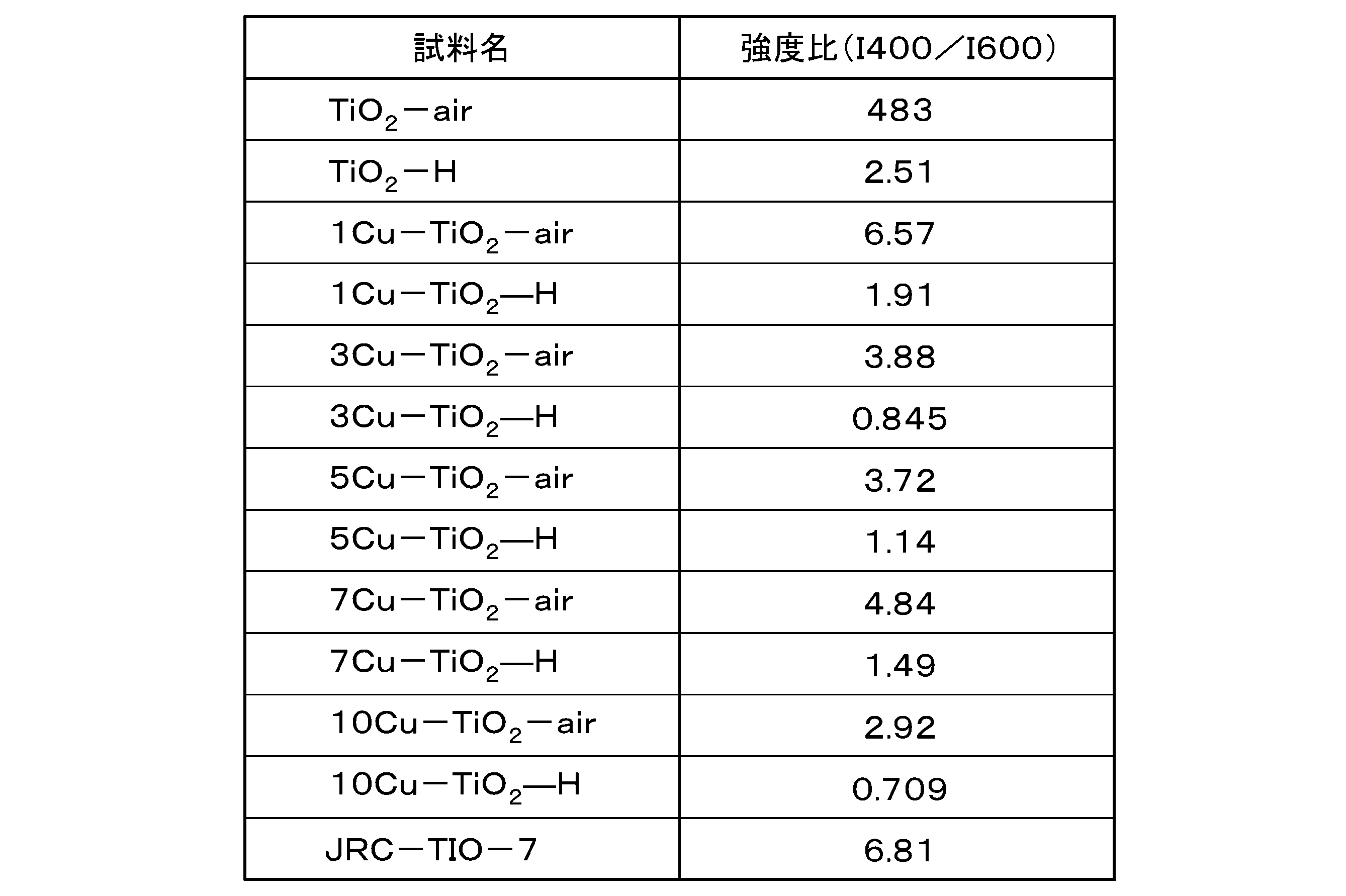
- the ratio I 400 /I 600 between the intensity I 400 at a wavelength of 400 nm and the intensity I 600 at a wavelength of 600 nm is preferably 0.5-3.
- a ratio of I 400 /I 600 between 0.5 and 3 leads to the incorporation of hydrogen into the lattice near the surface of TiO 2 .
- the presence of hydrogen near the surface of TiO 2 allows efficient supply of hydrogen from the TiO 2 interface during the reduction reaction occurring on Cu. This can further improve the selectivity of methane production.
- the ratio I 400 /I 600 can be measured by the following method. Measure the ultraviolet/visible absorption spectrum of the catalyst. The ratio I 400 /I 600 is calculated from the intensity I 400 at a wavelength of 400 nm and the intensity I 600 at a wavelength of 600 nm in the spectrum obtained by converting the obtained ultraviolet-visible absorption spectrum with the Kubelka-Munk function.
- XPS spectrum measured by X-ray photoelectron spectroscopy (XPS) of the catalyst
- XPS spectrum X-ray photoelectron spectroscopy
- the half-value width of the peak between is preferably 1.2 eV to 1.55 eV. Width at half maximum refers to full width at half maximum (FWHM).
- the conductivity can be improved by reducing the bandgap of the Ti-containing oxide on the surface of the catalyst. It also functions as a hydrogen source in the hydrogenation of introduced CO2 . This can improve the speed of the reduction reaction.
- the XPS spectrum of the catalyst has a peak between 931 eV and 933 eV, and the half width of the peak between 931 eV and 933 eV is between 1.4 eV and 1.9.
- the peaks between 931 eV and 933 eV are those originating from Cu 0 .
- having a peak between 931 eV and 933 eV means that the peak top (the value at which the intensity reaches its maximum value) is between 931 eV and 933 eV.
- the half width of the peak is between 1.4 eV and 1.9 eV
- Cu on the catalyst surface exists as Cu 0 . This improves the activity of the catalyst.
- the XPS spectrum of the catalyst is measured by the following method.
- the samples were measured with a spot size of 100 ⁇ m, cumulative times (O1s 10 times, Ti2P 3/2 10 times, Cu2p 3/2 40 times) using Al K ⁇ radiation.
- the half width was obtained by fitting with a mixed function of Gaussian function and Lorentzian function.
- the catalyst layer 22 may further contain a binder.
- the binder is not particularly limited, for example, electrolyte polymer is preferable.
- electrolyte polymers include Nafion (registered trademark), which is a fluororesin copolymer based on sulfonated tetrafluoroethylene.
- the binder content is, for example, 10 wt % to 50 wt %.
- the catalyst layer 22 may further contain conductive aids such as acetylene black and carbon nanotubes.
- the third channel structure 70 is arranged in contact with the substrate 21 of the cathode 20 .
- the third flow path structure 70 is in contact with the surface of the substrate 21 opposite to the surface provided with the catalyst layer 22 .
- the third channel structure 70 includes a third inlet 71 , a third outlet 72 , a gas chamber 73 and a gas channel 74 .
- a CO 2 -containing gas which will be described later, flows in the gas flow path 74 .
- the third channel structure 70 has an opening 70a for contacting the cathode 20 with the CO 2 -containing gas.
- the CO 2 -containing gas is sent from the gas delivery part 171 to the third inlet 71 .
- the CO 2 -containing gas entering the third inlet 71 enters the gas passage 74 and is sent to the gas chamber 73 .
- the reduction reaction of the cathode 20 proceeds, and the CO 2 -containing gas containing the gas product produced by the reduction reaction of the cathode 20 (hereinafter sometimes referred to as the produced gas) is discharged through the third outlet 72 . to the gas product recovery section 172 .
- the electrochemical reduction device 100 according to this embodiment has been described in detail above. According to the electrochemical reduction device 100 according to the present embodiment, it is possible to improve the selectivity of methane production in the CO 2 reduction reaction.
- the electrochemical reduction device 100 of this embodiment does not have a reference electrode, it may have a reference electrode.
- the reference electrode include a mercury-mercury oxide electrode (Hg/HgO).
- the first channel plate 30, the second channel plate 31, the third channel plate 32, and the fourth channel plate 33 are used, but each channel plate is not used.
- the gas discharge member 40 is provided with the opening 41 , the opening 41 may be omitted if gaseous substances such as O 2 generated by the oxidation reaction at the anode 10 can be removed.
- the electrochemical reduction method comprises a first electrolyte delivery step of sending a first electrolyte to the anode chamber 53, a second electrolyte delivery step of sending a second electrolyte to the cathode chamber 63, and a CO2 - containing It comprises a CO2 - containing gas delivery step of sending gas to the gas chamber 73 and an electrochemical reduction step of electrochemically reducing the CO2 .
- each process is performed in parallel, for example.
- first electrolytic solution delivery step In the first electrolytic solution delivery step, the first electrolytic solution is delivered from the first solution delivery part 151 to the anode chamber 53 . In addition, the product associated with the oxidation reaction occurring at the anode 10 is sent to the waste liquid collecting section 152 .
- the first electrolytic solution is an electrolytic solution containing at least water (H 2 O).
- the first electrolytic solution contains at least one selected from the group consisting of hydroxide ions, potassium ions, hydrogen ions, sodium ions, lithium ions, chloride ions, sulfate ions, carbonate ions, and nitrate ions.
- the electrolytic solution contained can be mentioned.
- electrolytes include potassium hydroxide and sodium hydroxide.
- the pH of the first electrolytic solution is pH 5-15.
- the pH of the first electrolytic solution is preferably 6 or higher. By setting the pH of the first electrolytic solution to be 5 to 15, the oxidation reaction at the anode 10 can be facilitated.
- the flow rate of the first electrolytic solution can be appropriately set according to the area of the anode 10 and the volume of the anode chamber 53.
- the second electrolyte delivery step In the second electrolyte delivery step, the second electrolyte is delivered from the second solution delivery section 161 to the cathode chamber 63 . Also, the product associated with the reduction reaction occurring in the cathode chamber 63 is sent to the liquid product recovery section 162 .
- the second electrolytic solution is an electrolytic solution containing at least water.
- the second electrolytic solution contains at least one selected from the group consisting of hydroxide ions, potassium ions, hydrogen ions, sodium ions, lithium ions, chloride ions, sulfate ions, carbonate ions, and nitrate ions.
- the electrolytic solution contained can be mentioned.
- electrolytes include potassium hydroxide and sodium hydroxide.
- the pH of the second electrolytic solution is pH 5-15.
- the pH of the second electrolytic solution is preferably 6 or higher.
- the pH of the first electrolytic solution and the pH of the second electrolytic solution are preferably the same.
- the flow rate of the second electrolytic solution can be appropriately set according to the area of the cathode 20 and the volume of the cathode chamber 63 .
- the flow rate of the second electrolytic solution is 0.5 ml min ⁇ 1 to 7 ml min ⁇ 1 .
- the CO 2 -containing gas is delivered from the gas delivery part 171 to the gas chamber 73 . Also, a gaseous product (gas product) associated with the reduction reaction occurring in the cathode chamber 63 is sent to the gaseous product recovery unit 172 .
- the CO2 concentration in the CO2 - containing gas is preferably 10 vol% or more with respect to the total volume of the CO2-containing gas. More preferably, the CO2 concentration in the CO2 -containing gas is 50 vol% or more. More preferably, the CO2 concentration in the CO2 -containing gas is 90 vol% or more. The upper limit of CO2 concentration is 100vol%.
- the flow rate of the CO 2 -containing gas can be appropriately set according to the area of the cathode 20 and the volume of the cathode chamber 63 .
- the flow rate of the CO 2 -containing gas is, for example, 1-15 sccm.
- the electrochemical reduction step electrochemically reduces CO2 .
- a voltage is applied between the anode 10 and the cathode 20 from the power source 140 to supply current.
- a current is passed between the anode 10 and the cathode 20 , an oxidation reaction proceeds near the anode 10 and a reduction reaction proceeds near the cathode 20 .
- methane (CH 4 ) is used as an example, but in the electrochemical reduction process, C 2 H 4 , CO, etc. may also be produced.
- CH 4 methane
- C 2 H 4 , CO, etc. may also be produced.
- the reaction between the anode 10 and the cathode 20 will be described separately.
- H 2 + generated at the anode 10 moves through the first electrolyte, the separator 15, the second electrolyte, and reaches the catalyst layer 22 of the cathode 20 .
- the current (e ⁇ ) supplied from the power supply 140 and the H + reaching the catalyst layer 22 of the cathode 20 advance the electrochemical reduction reaction of CO 2 .
- CO 2 in the CO 2 -containing gas supplied from the gas chamber 73 to the cathode 20 is reduced to CH 4 as shown in the following formula (5). That is, the electrochemical reduction of CO2 produces CH4 .
- the reaction at the cathode 20 described above proceeds on the catalyst of the catalyst layer 22 . That is, the CO 2 is electrochemically reduced while the catalyst of the catalyst layer 22 is in contact with the pH 5-15 solution and the CO 2 .
- a voltage applied between the anode 10 and the cathode 20 is, for example, 0V to -4.0V. More preferably, the voltage is between -1.0V and -2.5V. If the voltage is -1.0 V to -2.5 V, the electrochemical reduction reaction of CO 2 can proceed with higher energy conversion efficiency.
- the electrochemical reduction method according to this embodiment has been described above. According to the electrochemical reduction method of the present embodiment, the selectivity of CH4 generation can be improved in the electrochemical reduction method of CO2 .
- a method for producing a catalyst according to this embodiment will be described.
- raw materials are mixed, placed in a closed container, heated until the surface temperature of the closed container reaches a heating temperature, and then the heating temperature is maintained for 10 minutes or more to produce a precursor.
- a catalyst is produced using a solvothermal method.
- the raw materials include a titanium raw material containing titanium (Ti) and a copper raw material containing copper (Cu).
- titanium raw materials examples include titanium (IV) methoxide, titanium (IV) tetrabutoxide, titanium (IV) isopropoxide, and titanium diboride. Titanium (IV) tetrabutoxide is preferred as the titanium raw material.
- Copper raw materials are, for example, copper (II) acetate, copper (II) stearate, and copper (II) chloride. Copper (II) acetate is preferred as the copper source.
- the weight ratio (Ti:Cu) of titanium (Ti) contained in the titanium raw material and copper (Cu) contained in the copper raw material is preferably 1:99 to 99.99:0.01. More preferably, the weight ratio (Ti:Cu) is from 10:90 to 99:1. More preferably, the weight ratio (Ti:Cu) is from 50:50 to 93:7. If the weight ratio (Ti:Cu) is 99:1 to 90:10, Cu can be effectively isolated in the Ti-containing oxide. If possible, CH4 can be generated. If the Cu atoms are not isolated, the C—C bond of the two COs will produce a higher percentage of C2 compounds. By isolating Cu, the selectivity of methanation can be improved.
- the heating temperature of the closed container is preferably 60°C to 280°C. If the temperature is in the range of 60° C. to 280° C., the catalyst precursor can be produced in high yield.
- the heating temperature is more preferably 180°C to 220°C.
- the holding time after reaching the heating temperature of the sealed container is preferably 10 minutes or longer.
- a more preferable holding time is 1 hour or more.
- the firing temperature of the precursor is preferably 100°C to 800°C.
- the calcination temperature is more preferably 300°C to 500°C.
- the atmosphere when firing the precursor is not particularly limited.
- the atmosphere when firing the precursor may be the air or may be a hydrogen atmosphere.
- the H 2 concentration when firing the precursor is 0.5 vol % or more. More preferably, the H 2 concentration during firing is 5 vol % or more. More preferably, the H2 concentration is 99.9 vol % or higher. The upper limit of H2 concentration is 100 vol %. If the H 2 concentration is 1 vol % or more, at least part of the Cu in the catalyst can be in the Cu 0 state. In addition, hydrogen can be taken into the lattice near the surface of TiO 2 , and the selectivity of methane production can be improved.
- the cathode 20 is obtained by forming a catalyst layer 22 containing a catalyst on a porous and conductive substrate 21 .
- a method for forming the catalyst layer 22 is not particularly limited.
- the catalyst layer 22 may be formed on the substrate 21 by coating the substrate 21 with a dispersion liquid in which the catalyst is dispersed and drying it.
- the method of applying the dispersion liquid is not particularly limited.
- a spray may be used to apply the dispersion (catalyst ink).
- the dispersion liquid may contain a binder or the like.
- Titanium(IV) tetrabutoxide was quickly added to a mixture of 30 mL N,N-dimethylformamide (99.5%), 0.207 mL 2-propanol and copper(II) acetate, anhydrous.
- the PTFE container containing the mixture was transferred to a stainless steel autoclave, sealed, placed in an oven, and held at 200° C. for 20 hours.
- the resulting solid was centrifuged at 7500 rpm for 10 minutes. After separating the obtained precursor, it was washed several times with ethanol, acetone and hexane. The precursor was then dried under vacuum at room temperature. Finally, the precursor was heated (heat treated) at 450° C.
- a catalyst (xCu—TiO 2 -y).
- x in xCu-TiO 2 -y indicates the doping amount of Cu (x wt.%) in the catalyst.
- y in xCu—TiO 2 -y indicates the atmosphere during heating.
- y air when heating in air
- y H when heating in H 2 atmosphere.
- 1 mL of titanium (IV) tetrabutoxide was quickly added to a mixture of 30 mL of N,N-dimethylformamide (99.5%), 0.215 mL of 2-propanol and the desired loading of copper (II) acetate (anhydrous). .
- TiO 2 -y was obtained by synthesizing under the same conditions as xCu—TiO 2 -y except that copper (II) acetate was not added.
- the weight ratio (Ti:Cu) of titanium (Ti) in titanium (IV) tetrabutoxide and copper (Cu) in copper acetate is in the range of 100:0 to 90.5:9.5. prepared in
- the elemental composition of the prepared catalyst was measured by energy dispersive X-ray spectroscopy (EDS) using JED-2300 (JEOL).
- UV/visible absorption spectrum The ultraviolet/visible absorption spectrum of the catalyst was measured using V-670 (JASCO). The reflected intensity in the UV-visible absorption spectrum was converted into an intensity corresponding to the light absorption coefficient using the Kubelka-Munk function.
- XPS X-ray photoelectron spectroscopy
- a gas diffusion electrode (GDE) for the cathode was produced by the following method. Carbon paper (Fuel Cell Store Sigracet 22 BB, with a microporous layer) was used as a substrate. 200 ⁇ L of 2-propanol, 200 ⁇ L of water, 10 ⁇ L of Nafion® solution (Sigma-Aldrich 527084), and 1 mg of the catalyst powder synthesized above were mixed. The mixture was ultrasonically dispersed in a 4 mL screw vial for 15 minutes to make a catalyst ink. A cathode was produced by spraying the obtained catalyst ink onto carbon paper with an airbrush.
- the electrochemical CO 2 reduction reaction (ECO 2 R) was performed in a three-electrode system electrochemical reduction apparatus in which a reference electrode (mercury-mercury oxide electrode (Hg/HgO)) was added to the electrochemical reduction apparatus shown in FIG. rice field.
- a reference electrode mercury-mercury oxide electrode (Hg/HgO)
- Hg/HgO mercury-mercury oxide electrode
- a cathode manufactured by the above method was used as the cathode, and a nickel foam was used as the anode.
- the electrode area of the cathode in the electrochemical reduction device was 1 cm 2 .
- a Nafion® 117 cation exchange membrane was used to separate the cathode and anode compartments.
- the gaseous products produced in the electrochemical CO2 reduction reaction were analyzed using a micro GC (Inficon Micro GC Fusion®) combining Molsieve 5A and Plot Q columns with a thermal conductivity detector (TCD). analyzed.
- a micro GC Inficon Micro GC Fusion®
- TCD thermal conductivity detector
- the liquid products produced in the electrochemical CO 2 reduction reaction were analyzed by a high performance liquid chromatograph (HPLC, LC-20AD, Shimadzu) with a refractive index detector (RID-10A, Shimadzu Corporation).
- FE The faradaic efficiency (FE) of the product is defined by equation (8) below.
- n i in formula (2) represents the number of moles of product i
- z i in formula (8) represents the number of electrons required to generate product i.
- CO formic acid
- F in equation (8) is the Faraday constant (96,485 C mol ⁇ 1 ).
- Q in equation (8) is the amount of charge that has flowed through ECO 2 R.
- ni was calculated based on the following formula (9).
- x i is the volume fraction of gas product i
- P 0 is the atmospheric pressure (1 atm)
- ⁇ is the flow rate of CO 2 (0.015 L min ⁇ 1 )
- t is the reaction time
- R is the gas constant (0.08205 L ⁇ atm ⁇ mol ⁇ 1 K ⁇ 1 )
- T 298K.
- FIG. 2 shows the relationship between the starting composition of Cu and the elemental composition determined by EDS measurement for the xCu—TiO 2 sample obtained.
- the horizontal axis in FIG. 2 represents the Cu content (wt%) at the start of synthesis, and the vertical axis in FIG. 2 represents the Cu content (wt%) in the catalyst after synthesis.
- the elemental composition determined by EDS measurement was in good agreement with the starting compositional ratio, confirming that the target amount of Cu was contained.
- FIG. 3 shows the XRD patterns of the catalyst (xCu—TiO 2 -air), anatase TiO 2 and brookite TiO 2 obtained by heat treatment in air.
- the horizontal axis in FIG. 3 is 2 ⁇ (degree), and the vertical axis is intensity (a.u.).
- FIG. 4 shows the XRD patterns of the catalyst (xCu—TiO 2 -air), anatase TiO 2 , brookite TiO 2 and Cu obtained by heat treatment in a hydrogen atmosphere.
- the horizontal axis in FIG. 4 is 2 ⁇ (degree), and the vertical axis is intensity (a.u.).
- FIG. 5 shows the O1s XPS spectra of the catalysts obtained by heat treatment in air or in a hydrogen atmosphere while varying the Cu content. As shown in FIG. 5, a peak was confirmed between 528 eV and 532 eV (O1s peak).
- FIG. 5 shows TiO 2 (TiO 2 ) with 0 wt% Cu, 1Cu—TiO 2 with 1 wt% Cu added, 3Cu—TiO 2 with 3 wt% Cu added, 5Cu—TiO 2 with 5 wt% Cu added, and 7Cu with 7 wt% Cu added.
- a solid line in each XPS spectrum indicates heat treatment in a hydrogen atmosphere (H 2 ), and a dashed line in each XPS spectrum indicates heat treatment in air (air).
- the horizontal axis in FIG. 5 indicates binding energy (eV), and the vertical axis indicates normalized intensity (au). Further, fitting was performed on the obtained O1s peak to obtain the full width at half maximum (FWHM) (unit: eV) of the O1s peak. Table 1 shows the results obtained. As shown in FIG. 5 and Table 1, the XPS spectra of O1s were almost the same except for 10Cu--TiO 2 -air and 10Cu--TiO 2 -H 2 .
- FIG. 6 shows Ti2p 3/2 XPS spectra of catalysts obtained by heat treatment in air or in a hydrogen atmosphere while varying the Cu content. As shown in FIG. 6, a peak (Ti2p 3/2 peak) was confirmed between 457 eV and 460 eV.
- FIG. 6 shows TiO 2 (TiO 2 ) with 0 wt% Cu, 1Cu—TiO 2 with 1 wt% Cu added, 3Cu—TiO 2 with 3 wt% Cu added, 5Cu—TiO 2 with 5 wt% Cu added, and 7Cu with 7 wt% Cu added.
- a solid line in each XPS spectrum indicates heat treatment in a hydrogen atmosphere (H 2 ), and a dashed line in each XPS spectrum indicates heat treatment in air (air).
- the horizontal axis in FIG. 6 indicates binding energy (eV), and the vertical axis indicates normalized intensity (au). Further, fitting was performed on the obtained Ti2p 3/2 peak to obtain the full width at half maximum (FWHM) (unit: eV) of the obtained Ti2p 3/2 peak. Table 2 shows the results obtained.
- FIG. 7 shows Cu2p 3/2 XPS spectra of catalysts obtained by heat-treating in air or in a hydrogen atmosphere while varying the Cu content. As shown in FIG. 7, a peak was confirmed between 931 eV and 933 eV ( Cu2p 3/2 peak).
- Fig. 2 is the Cu2p 3/2 XPS spectra of 5Cu-TiO 2 doped with , 7Cu-TiO 2 doped with 7 wt% Cu, and 10Cu-TiO 2 doped with 10 wt% Cu.
- a solid line in each XPS spectrum indicates heat treatment in a hydrogen atmosphere (H 2 )
- a dashed line in each XPS spectrum indicates heat treatment in air (air).
- the xCu—TiO 2 —H spectrum in FIG. 7 gave a Cu 2p 3/2 peak centered at 932.6 eV. This peak is assigned to Cu 0 . In other words, it was found that in xCu--TiO 2 --H, it exists mainly as Cu 0 on the TiO 2 surface.
- FIG. 8 shows ultraviolet/visible absorption spectra of catalysts obtained by heat-treating in the atmosphere while varying the Cu content.
- the horizontal axis in FIG. 8 is the wavelength (nm), and the vertical axis corresponds to the light absorption coefficient, which is the Kubelka-Munk transformed reflectance R (a.u.).
- TiO 2 -air was a white powder and exhibited strong absorption in the ultraviolet region.
- the bandgap of the catalyst was calculated by Tauc plot.
- the Tauc plot is expressed by the above formula (2) in which the vertical axis value F (R ⁇ ) of the Kubelka-Munk transformed spectrum is substituted for the extinction coefficient ⁇ in the above formula (1) proposed by Tauc, Davis, Mott et al. Based on Here, h: Planck's constant, ⁇ : frequency, ⁇ : extinction coefficient, Eg: bandgap, A: constant of proportionality, where n is determined by the type of transition of the sample.
- the absorption peak shifts slightly to the visible region as the Cu content increases, and in addition, the absorption bands between 400 nm to 500 nm and 550 nm to 1500 nm. Appeared.
- the first absorption band from 400 to 500 nm is attributed to interfacial charge transfer from the O2p orbital forming the valence band of TiO2 to the Cu(II) state attached to TiO2
- the absorption band from 550 nm to 1500 nm is attributed to Cu( II) attributed to the dd transition. From this result, it was found that Cu on xCu--TiO 2 -air exists as Cu(II), similar to the XPS result.
- FIG. 9 shows ultraviolet/visible absorption spectra of catalysts obtained by heat treatment in a hydrogen atmosphere while varying the Cu content.
- the horizontal axis of FIG. 9 is the wavelength (nm), and the vertical axis corresponds to the light absorption coefficient, which is the Kubelka-Munk transformed reflectance R (a.u.).
- TiO 2 —H and 1Cu—TiO 2 —H obtained by heat treatment in a hydrogen atmosphere were dark brown powders, and exhibited peculiar absorption not observed in white TiO 2 over the near-infrared region from 400 nm.
- Table 5 shows the ratio I 400 /I 600 between the intensity at 400 nm and the intensity at a wavelength of 600 nm obtained from FIGS. As shown in Table 5, the ratio I 400 /I 600 of the catalyst heat-treated in the hydrogen atmosphere tended to be lower than that of the catalyst heat-treated in the atmosphere.
- TiO 2 -air-H 2 in FIG. 10 indicates a catalyst obtained by heating TiO 2 -air at 450° C. for 30 minutes in a hydrogen atmosphere, and TiO 2 -air-H-air is TiO 2 -air-H 2 was again heated at 450° C. for 30 minutes in the atmosphere.
- TiO 2 -air-H obtained by hydrogen-treating white TiO 2 -air also exhibited a deep brown color and showed absorption in the visible to near-infrared region, like TiO 2 -H. Furthermore, the sample TiO 2 -air-H-air obtained by heating this TiO 2 -air-H again in air was white and exhibited a spectrum similar to that of TiO 2 -air, and did not exhibit absorption in the visible to near-infrared region. . Therefore, it was suggested that the peculiar absorption observed in the absorption spectra of TiO 2 --H and 1Cu--TiO 2 --H was caused by hydrogen being incorporated into the lattice near the TiO 2 surface.
- FIG. 11 shows the results of C 1s XPS measurements of xCu--TiO 2 -air and xCu--TiO 2 -H for the purpose of detecting carbon from the organotitanium source that may be doped in the TiO 2 lattice.
- Doped carbon exhibits a peak attributed to carbon ions at about 281.8 eV, which is different from the main peak of impurity-derived C1s with a binding energy of 284.6 eV (CC). As shown in FIG.
- xCu--TiO 2 -air and xCu--TiO 2 -H did not have a carbon ion peak (281.8 eV), and no significant difference was observed between the catalysts. Therefore, it was confirmed that the absorption in the visible region observed in the ultraviolet/visible absorption spectrum of xCu—TiO 2 —H is not due to doped carbon.
- FIG. 13 shows high-angle dark-field scanning transmission electron micrographs obtained by heat treatment in a hydrogen atmosphere with varying Cu contents.
- a high-angle dark-field scanning transmission electron microscope (HAADF-STEM) image confirmed that the Cu species were highly dispersed.
- FIG. 14 shows the relationship between the Cu content and the partial current density for methanation.
- the horizontal axis of FIG. 14 indicates the Cu content (wt %), and the vertical axis indicates the partial current density for methanogenesis (mAcm ⁇ 2 ).
- CH4 was produced even without Cu
- the loading of Cu greatly enhanced the partial current density for CH4 production.
- the hydrogen-treated catalyst xCu-- TiO.sub.2 --H showed a dramatic improvement in current density compared to xCu-- TiO.sub.2 --air. It is believed that the content of Cu and the heat treatment in a hydrogen atmosphere increased the activity of the catalyst.
- FIG. 15 shows the relationship between the product distribution and the current density when ECO 2 R was performed using the 5Cu—TiO 2 —H catalyst.
- the horizontal axis of FIG. 15 indicates current density (mAcm ⁇ 2 ), the first vertical axis indicates Faraday efficiency (%), and the second vertical axis indicates IR free voltage (V vs. RHE).
- the selectivity to CH 4 in the CO 2 reduction products was 90% when using the 5Cu—TiO 2 —H catalyst. From the above, it was found that the catalyst of the present disclosure can selectively reduce CO2 to CH4 . Faradaic efficiency to CH 4 was 50% and partial current density for CH 4 production was 100 mA cm ⁇ 2 .
- the electrochemical reduction method, catalyst, and catalyst production method of the present disclosure can improve the selectivity of CH4 generation in the electrochemical reduction reaction of CO2 , and therefore have high industrial applicability.
Landscapes
- Chemical & Material Sciences (AREA)
- Organic Chemistry (AREA)
- Engineering & Computer Science (AREA)
- Materials Engineering (AREA)
- Chemical Kinetics & Catalysis (AREA)
- Electrochemistry (AREA)
- Metallurgy (AREA)
- Physics & Mathematics (AREA)
- Thermal Sciences (AREA)
- Ceramic Engineering (AREA)
- Catalysts (AREA)
Abstract
Description
本願は、2021年3月2日に、米国に仮出願されたUS63/155,309号に基づき優先権を主張し、その内容をここに援用する。
Tiを含む酸化物を含有する触媒に、
pH5~15の溶液と、CO2と、を接触させた状態で、
前記CO2を電気化学的に還元する。
前記CO2を電気化学的に還元することで、メタンを生成してもよい。
前記Tiを含む酸化物の少なくとも一部のバンドギャップが3eV以下であってもよい。
前記触媒における前記Tiを含む酸化物の含有量が10wt%以上であってもよい。
前記触媒がCuを含有してもよい。
以下、図面を参照して、実施形態に係る電気化学的還元方法に用いる電気化学的還元装置100について説明する。以下の説明で用いる図面は、特徴をわかりやすくするために便宜上特徴となる部分を拡大して示している場合があり、各構成要素の寸法比率などは実際とは異なっていることがある。以下の説明において例示される材料、寸法等は一例であって、本発明はそれらに限定されるものではなく、本発明の効果を奏する範囲で適宜変更して実施することが可能である。
アノード10は、第1流路板30とガス排出部材40との間に配置される。アノード10は、第1流入口51からアノード室53に流入した後述する第1電解液を酸化して、酸素、水素イオンなどを生成する。第1電解液を酸化して生成された生成物のうち、第1電解液に溶解した物質は第1流出口52を通り、排出される。また、気体状の生成物、例えばO2は、アノード10から、ガス排出部材40の開口部41を通り、排出される。
アノード10は、例えば、多孔質材である。アノード10の材質は、例えば、ニッケル、チタン、鉄等の金属、またはこれらの金属を含有する合金である。アノード10の具体例としては、例えばニッケルフォームである。
電気化学還元装置100において、ガス排出部材40は、アノード10と蓋部材45の間に配置される。アノード10とガス排出部材40との間には、別途流路板などが配置されてもよい。ガス排出部材40はアノード10の酸化反応で生じた気体状の生成物を排出するための開口部41を備えてもよい。ガス排出部材40は開口部41を備えなくてもよい。アノード10上で起こる酸化反応で生じた気体生成物(酸素)は、開口部41あるいは第1流出口52から電解液とともに排出される。
電気化学還元装置100において、蓋部材45は、ガス排出部材40に接して配置される。
第1流路板30は、第1流路構造体50とアノード10との間に配置される。第1流路板30には、第1電解液とアノード10とが接触できるように開口部30aが設けられている。第1流路板30の材質は、化学的に安定で、絶縁性を有していれば特に限定されない。第1流路板30の材質としては、例えば、ポリエーテルエーテルケトン(PEEK)、フッ素樹脂、ガラスなどが挙げられる。
電気化学還元装置100では、第1流路構造体50は、第1流路板30と第2流路板31との間、または、第1流路板30とセパレータ15との間に配置される。第1流路構造体50は第1流入口51、第1流出口52、アノード室53、および流路54を備える。第1流路構造体50は、アノード10と第1電解液とを接触させるための開口部50aを備える。また、第1流路構造体50は、セパレータ15と第1電解液とを接触させるための開口部50bを備える。
第2流路板31は、セパレータ15と第1流路構造体50との間に配置される。第2流路板31の材質は、化学的に安定で、絶縁性を有していれば特に限定されない。第2流路板31の材質としては、例えば、ポリエーテルエーテルケトン(PEEK)、フッ素樹脂、ガラスなどが挙げられる。第2流路板31は、セパレータ15と第1電解液とを接触させる開口部31aを備える。電気化学還元装置100は、第2流路板31を取り付けなくても機能するが、液漏れを簡便に防ぐためには設置することが望ましい。
セパレータ15は、アノード10とカソード20との間に配置される。本実施形態では、第2流路板31と第3流路板32との間に配置されている。セパレータ15により、アノード10とカソード20とを分離し、かつ、アノード10とカソード20との間で一部のイオンを移動させることができる。セパレータ15は、アノード10とカソード20とを分離し、かつ、アノード10とカソード20との間で一部のイオンを移動させることができれば、特に限定されない。セパレータ15としては例えば、イオン交換膜が挙げられる。イオン交換膜としては、例えば、スルホ化されたテトラフルオロエチレンを基にしたフッ素樹脂の共重合体であるナフィオン(登録商標)膜、1-メチルイミダゾールで官能基化したスチレンと塩化ビニルベンジルの共重合体であるSustainion(登録商標) X37-50 Grade RT Membraneなどが挙げられる。
第3流路板32は、セパレータ15と第2流路構造体60との間に配置される。第3流路板32の材質は、化学的に安定で、絶縁性を有していれば特に限定されない。第3流路板32の材質としては、例えば、ポリエーテルエーテルケトン(PEEK)、フッ素樹脂、ガラスなどが挙げられる。第3流路板32は、セパレータ15と第1電解液とを接触させる開口部32aを備える。電気化学還元装置100は、第3流路板32を取り付けなくても機能するが、液漏れを簡便に防ぐためには設置することが望ましい。
第2流路構造体60は、第3流路板32と第4流路板33、あるいはセパレータ15と第4流路板33との間に配置される。第2流路構造体60は、第2流入口61、第2流出口62、カソード室63、および流路64を備える。流路64において、後述する第2電解液が流れる。第2流路構造体60は、セパレータ15と第2電解液とを接触させるための開口部60aを備える。また、第2流路構造体60は、カソード20と第2電解液とを接触させるための開口部60bを備える。
第4流路板33は、カソード20と第2流路構造体60との間に配置される。第4流路板33の材質は、化学的に安定で、絶縁性を有していれば特に限定されない。第4流路板33の材質としては、例えば、ポリエーテルエーテルケトン(PEEK)、フッ素樹脂、ガラスなどが挙げられる。第4流路板33は、カソード20と第2電解液とを接触させる開口部33aを備える。
カソード20は、第3流路構造体70と第4流路板33との間に配置される。カソード20は、基板21と触媒層22とを備える。
(hνα)1/n=A(hν-Eg) (1)
(hνF(R∞))1/n=A(hν-Eg) (2)
ここで,h:プランク定数、ν:振動数、α:吸光係数、Eg:バンドギャップ、A:比例定数を意味する。nは試料の遷移の種類によって決まり、直接許容遷移の場合はn=1/2、直接禁制遷移の場合はn=3/2、間接許容遷移の場合はn=2、間接禁制遷移の場合はn=3とする。アナターゼ型TiO2は間接遷移型半導体であるため,n=1/2とする。Kubelka-Munk変換したスペクトルをもとに横軸hν、縦軸hνF(R∞))1/2のグラフ上に(hν,hνF(R∞))1/2)の値をプロットすると、吸収端付近の吸収曲線は直線的になり、この付近に重なるように接線を引き横軸との交点を求めると、バンドギャップが求めることができる。
第3流路構造体70は、カソード20の基板21に接して配置される。第3流路構造体70は、基板21の触媒層22が設けられた面と反対の面に接している。第3流路構造体70は、第3流入口71、第3流出口72、ガス室73、およびガス流路74を備える。ガス流路74において、後述するCO2含有ガスが流れる。第3流路構造体70は、カソード20とCO2含有ガスとを接触させるための開口部70aを備える。
次に、本実施形態に係る電気化学還元方法について説明する。本実施形態に係る電気化学還元方法は、Tiを含む酸化物を含有する触媒に、pH5~15の溶液と、CO2と、を接触させた状態で、CO2を電気化学的に還元する。以下、電気化学還元装置100を用いた電気化学還元方法を行う方法を説明するが、本発明は、電気化学還元装置100を用いた方法に限定されない。
第1電解液送出工程では、第1溶液送出部151からアノード室53に第1電解液を送出する。また、アノード10で起こった酸化反応に伴う生成物を廃液回収部152に送る。
第2電解液送出工程では、第2溶液送出部161からカソード室63に第2電解液を送出する。また、カソード室63で起こった還元反応に伴う生成物を液体生成物回収部162に送る。
CO2含有ガス送出工程では、気体送出部171からガス室73にCO2含有ガスを送出する。また、カソード室63で起こった還元反応に伴う気体状の生成物(ガス生成物)を気体生成物回収部172に送る。
電気化学的還元工程では、CO2を電気化学的に還元する。具体的には、電源140からアノード10とカソード20との間に電圧を印加して電流を供給する。アノード10とカソード20との間に電流を流すとアノード10付近で酸化反応が進行し、カソード20付近で還元反応が進行する。以下の反応では、メタン(CH4)を例に挙げて説明するが、電気化学的還元工程では、他にC2H4,COなどが生成されてもよい。アノード10とカソード20との反応に分けて説明する。
2H2O→4H++O2+4e-・・・(3)
pHが7超の場合は、下記の式(4)に示すように、第1電解液中に含まれるOH-が酸化されて酸素と水が生じる。
4OH-→O2+2H2O+4e―・・・(4)
CO2+8H++8e-→CH4+2H2O・・・(5)
pHが7超の場合は、下記の式(6)に示すように、第1電解液中に含まれるCO2が還元され、H2Oと反応して、CH4とOH-が生じる。生成したOH-はセパレータを通ってアノードに運ばれる。
CO2+6H2O + 8e-→CH4+8OH-・・・(6)
次に、本実施形態に係る触媒の製造方法について説明する。本実施形態に係る触媒の製造方法は、原料を混合して、密閉容器に入れ、当該密閉容器の表面温度が加熱温度となるまで加熱した後、当該加熱温度を10分以上保持して前駆体を作製し、作製した前記前駆体を焼成温度で1分以上焼成して触媒を製造する。本実施形態では、ソルボサーマル法を用いた触媒を製造する。以下、本実施形態に係る触媒の製造方法について説明する。
本実施形態に係る触媒の製造方法において、原料は、チタン(Ti)を含有するチタン原料と銅(Cu)を含有する銅原料とを含む。
カソード20は、多孔質であり、導電性を有する基板21上に、触媒を含有する触媒層22を形成することで得られる。触媒層22を形成する方法は、特に限定されない。例えば、触媒を分散した分散液を基板21に塗布し乾燥することで触媒層22を基板21上に形成してもよい。
チタン(IV)テトラブトキシドをN,N-ジメチルホルムアミド(99.5%)30mL、2-プロパノール0.207mLおよび酢酸銅(II)、無水の混合物に素早く添加した。混合物が入ったPTFE容器をステンレス製のオートクレーブに移して密閉しオーブンに入れ200℃で20時間保持した。得られた固形物を7500rpmで10分間遠心分離を行った。得られた前駆体を分離した後、エタノール、アセトン、ヘキサンで数回洗浄した。その後、前駆体を真空下、室温で乾燥させた。最後に、前駆体を空気または水素気流中(60 ml min-1)で450℃で30分間加熱(加熱処理)して触媒(xCu-TiO2-y)を得た。なお、xCu-TiO2-yのxは触媒中のCuのドープ量(x wt.%)を示す。xCu-TiO2-yのyは加熱時の雰囲気を示す。ここでは、大気下で加熱した場合をy=airとし、H2雰囲気中で加熱した場合、y=Hとした。チタン(IV)テトラブトキシド1mLをN,N―ジメチルホルムアミド(99.5%)30mL、 2―プロパノール0.215 mLおよび目的の担持量相当の酢酸銅(II)(無水)の混合物に素早く添加した。1Cu―TiO2の調製には、6.64mgの酢酸銅(II)(無水)を用いた。また、同様に酢酸銅(II)を添加しない以外は、xCu-TiO2-yと同じ条件で合成し、TiO2-yを得た。TiO2-yのyは、加熱時の雰囲気を示す。ここでは、大気下で加熱した場合をy=airとし、H2雰囲気中で加熱した場合、y=Hとした。なお、チタン(IV)テトラブトキシド中のチタン(Ti)と、酢酸銅に含まれる銅(Cu)と、の重量比(Ti:Cu)は、100:0~90.5:9.5の範囲で調製した。
調製した触媒の元素組成は,JED-2300 (JEOL)を用いてエネルギー分散型X線分光法(EDS)で測定した。
触媒の粉末X線回折(XRD)パターンは、理研物質科学ビームライン BL44B2で取得した。
触媒の紫外・可視吸収スペクトルは,V-670 (JASCO)を用いて測定した。紫外・可視吸収スペクトルにおける反射強度を,Kubelka-Munk関数を用いて光吸収係数に対応する強度に変換した。
触媒のX線光電子分光(XPS)スペクトルは、VersaProbeII (ULVAC-PHI)を用いて、Al Kα線を使用して行った。XPSスペクトルの結合エネルギーは、試料中の配位子の炭素原子のC1s結合エネルギーを284.5eVとし、補正した。
触媒の走査透過電子顕微鏡(STEM)はJEM-ARM200F(JEOL)を用いて200kVで行った。
カソード用のガス拡散電極(GDE)は、以下の方法で作製した。基板としてカーボンペーパー(Fuel Cell Store Sigracet 22 BB、マイクロポーラス層付き)を用いた。2-プロパノール200μL、水200μL、Nafion(登録商標)溶液(Sigma―Aldrich 527084)10μL、および上記で合成した触媒粉末1mgを混合した。混合物を、4mLスクリューバイアルに入れ15分間超音波分散させて、触媒インクを作製した。得られた触媒インクをカーボンペーパーにエアブラシで噴霧することで、カソードを作製した。
電気化学的CO2還元反応(ECO2R)は、図1に示す電気化学還元装置に参照電極(水銀-酸化水銀電極(Hg/HgO))を追加した三電極系の電気化学還元装置で行った。カソードは上記の方法で製造したカソードを用い、アノードにはニッケルフォームを用いた。電気化学還元装置内のカソードの電極面積は1cm2とした。カソード室とアノード室の仕切りには、ナフィオン(登録商標)117陽イオン交換膜を使用した。
E(vs.RHE)=E(vs.Hg/HgO)+0.098V+0.0591V×pH・・・(7)
電気化学的CO2還元反応で生成された気体生成物は、Molsieve 5AカラムとPlot Qカラムに熱伝導度検出器(TCD)を組み合わせたマイクロGC(Inficon Micro GC Fusion (登録商標))を用いて分析した。


図2に得られたxCu-TiO2サンプルに対するCuの出発組成とEDS測定で決定された元素組成の関係を示す。図2の横軸は、合成出発時のCu含有量(wt%)を表し、図2の縦軸は、合成後の触媒中のCu含有量(wt%)を示す。図2に示すように、EDS測定で決定された元素組成は、出発組成比とよく一致しており、概ね目的量のCuが含有されていることが確認された。
図3に、大気下で加熱処理して得られた触媒(xCu-TiO2-air)、アナターゼTiO2、およびブルッカイトTiO2のXRDパターンを示す。図3の横軸は、2θ(degree)であり、縦軸は強度(a.u.)である。図4に、水素雰囲気下で加熱処理して得られた触媒(xCu-TiO2-air)、アナターゼTiO2、ブルッカイトTiO2、およびCuのXRDパターンを示す。図4の横軸は、2θ(degree)であり、縦軸は強度(a.u.)である。
図5にCu含有量を変えて大気下または水素雰囲気下で加熱処理して得られた触媒のO1sのXPSスペクトルを示す。図5に示す通り、528eV~532eVの間にピークが確認された(O1sピーク)。図5は、Cu0wt%のTiO2(TiO2)、Cu1wt%を添加した1Cu-TiO2、Cu3wt%を添加した3Cu-TiO2、Cu5wt%を添加した5Cu-TiO2、Cu7wt%を添加した7Cu-TiO2、およびCu10wt%を添加した10Cu-TiO2のO1sのXPSスペクトルである。各XPSスペクトルの実線は、水素雰囲気下(H2)で加熱処理したことを示し、各XPSスペクトルの破線は、大気下(air)で加熱処理したことを示す。図5中の横軸は、結合エネルギー(eV)を示し、縦軸は、規格化した強度(a.u.)を示す。また、得られたO1sピークに対しフィッティングを行い、O1sピークの半値全幅(FWHM)(単位eV)を得た。得られた結果を表1に示す。図5および表1に示すように、O1sのXPSスペクトルは10Cu-TiO2-air、10Cu-TiO2-H2を除き、ほぼ同じであった。このことは、熱処理の雰囲気やCuの含有量の違いによらずxCu-TiO2-yの表面付近のO原子が同様の結合環境を有することが分かった。10Cu-TiO2-airのスペクトルの違いはCu(II)種に起因するものであると考えられる。すなわち、Cu-TiO2-airおよびCu-TiO2-Hの表面には酸素欠陥が存在しないことが明らかとなった。

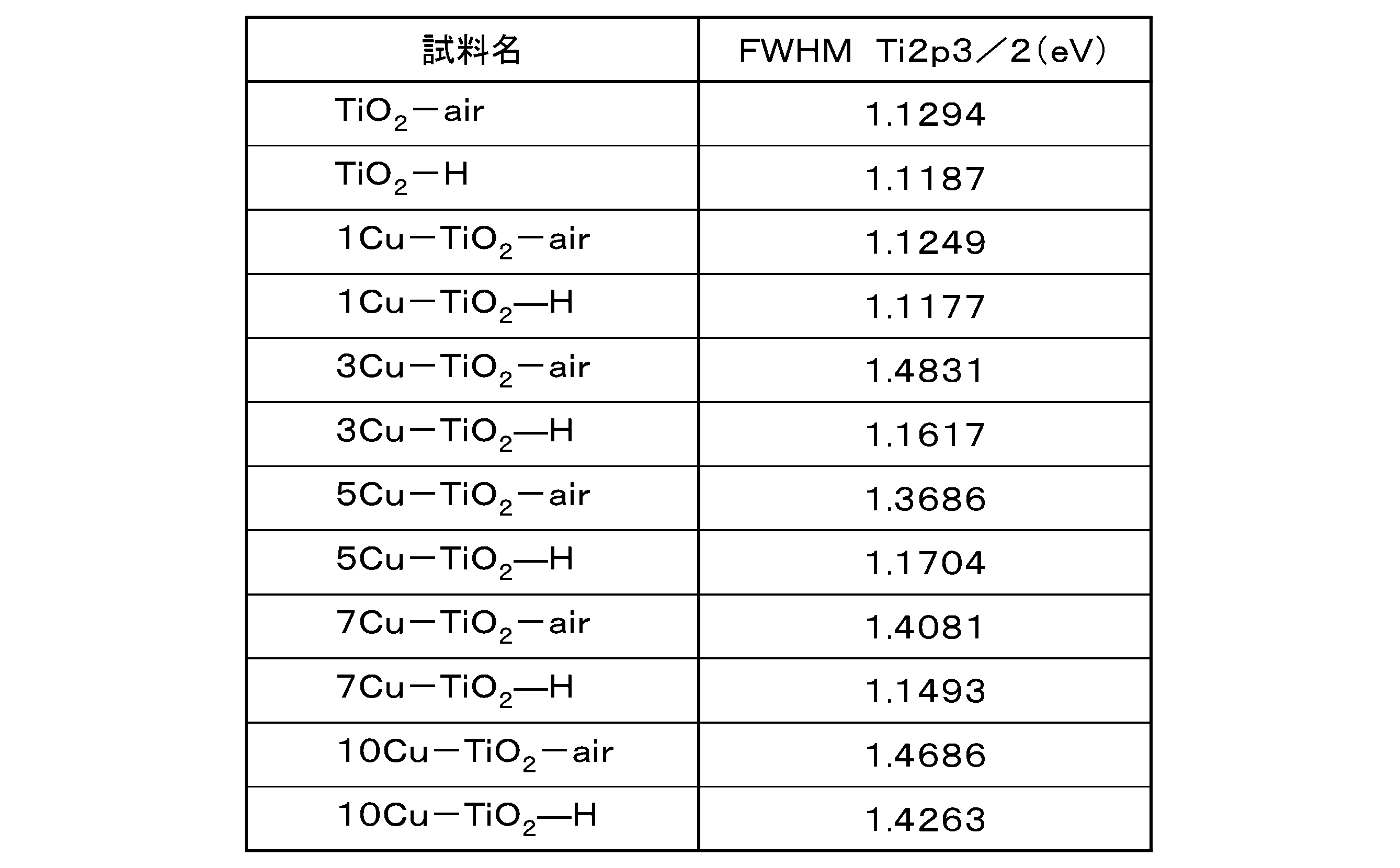

図8は、Cu含有量を変えて大気下で加熱処理して得られた触媒の紫外・可視吸収スペクトルである。図8の横軸は、波長(nm)であり、縦軸は、光吸収係数に対応しており、反射率RをKubelka-Munk変換したもの(a.u.)である。
ここで, h:プランク定数、ν:振動数、α:吸光係数、Eg:バンドギャップ、A:比例定数でnは試料の遷移の種類によって決まり、直接許容遷移の場合はn=1/2、直接禁制遷移の場合はn=3/2、間接許容遷移の場合はn=2、間接禁制遷移の場合はn=3とする。アナターゼ型TiO2は間接遷移型半導体であるため,n=1/2とする。Kubelka-Munk変換したスペクトルをもとに横軸hν、縦軸hνF(R∞))1/2のグラフ上に(hν,hνF(R∞))1/2)の値をプロットすると、 吸収端付近の吸収曲線は直線的になり、この付近に重なるように接線を引き横軸との交点を求めると、バンドギャップが求めることができる。Taucプロットにより算出した各触媒のバンドギャップの値を表4に示す。触媒学会の参照触媒JRC-TIO-7 (アナターゼ型酸化チタン)のバンドギャップ(3.24eV)よりも小さい。

この結果から、XPSの結果と同様にxCu-TiO2-air上のCuはCu(II)として存在することがわかった。
白色のTiO2-airを水素処理して得たTiO2-air-HもTiO2-Hと同様に濃い茶色を呈し可視から近赤外領域にかけて吸収を示した。さらにこのTiO2-air-Hを再び空気中で加熱したサンプルTiO2-air-H-airは白色でTiO2-airと同様のスペクトルを示し、可視から近赤外領域に吸収を示さなかった。したがってTiO2-Hや1Cu-TiO2-Hの吸収スペクトルで観測された特異な吸収は、水素がTiO2表面近傍の格子内に取りこまれたことによって発現したことが示唆された。
CがドープされたTiO2も可視から近赤外領域に吸収を示す。TiO2格子にドープされた可能性のある有機チタン原料由来の炭素を検出することを目的としてxCu-TiO2-airおよびxCu-TiO2-HのC 1s XPS測定した結果を図11に示す。ドープされた炭素は、約281.8 eVに炭素イオンに帰属されるピークを示し、不純物由来のC1sのメインピークの結合エネルギー284.6 eV(C-C)のピークとは異なる。図11に示すように、xCu-TiO2-airおよびxCu-TiO2-Hには、炭素イオンピーク(281.8eV)が存在せず、触媒間で目立った差異は見られなかった。そのため、xCu-TiO2-Hの紫外・可視吸収スペクトルで観察された可視域の吸収がドープした炭素に由来するものではないことを確認した。
図13に、Cu含有量を変えて水素雰囲気下で加熱処理して得られた高角度暗視野走査透過電子顕微鏡を示す。高角度暗視野走査透過電子顕微鏡(HAADF-STEM)像からは、Cu種が高分散に担持されていることが確認された。
図14にCu含有量とメタン生成の部分電流密度との関係を示す。図14の横軸は、Cu含有量(wt%)を示し、縦軸はメタン生成に対する部分電流密度を示す(mAcm-2)。CuなしでもCH4を生成したが、Cuの担持によってCH4生成に対する部分電流密度が大きく向上した。特に、水素処理した触媒xCu-TiO2-HではxCu-TiO2-airと比較して飛躍的に電流密度が向上した。Cuの含有量と水素雰囲気下での加熱処理により、触媒の活性が増大したと考えられる。
図15に示すように、5Cu-TiO2-H触媒を用いた場合、CO2還元生成物中のCH4への選択性が90%であった。以上のことから、本開示の触媒はCO2をCH4へと選択的に還元できることがわかった。CH4へのファラデー効率は50%、CH4生成に対する部分電流密度は100 mA cm-2であった。
蓋部材、50 第1流路構造体、60 第2流路構造体、70 第3流路構造体、100 電気化学還元装置、140 電源、151 第1溶液送出部、152 廃液回収部、161 第2溶液送出部、162 液体生成物回収部、171 気体送出部、172 気体生成物回収部
Claims (29)
- Tiを含む酸化物を含有する触媒に、
pH5~15の溶液と、CO2と、を接触させた状態で、
前記CO2を電気化学的に還元する、電気化学的還元方法。 - 前記CO2を電気化学的に還元することで、メタンを生成する、請求項1に記載の電気化学的還元方法。
- 前記Tiを含む酸化物の少なくとも一部のバンドギャップが3eV以下である、請求項1または2に記載の電気化学的還元方法。
- 前記触媒における前記Tiを含む酸化物の含有量が10wt%以上である、請求項1~3のいずれか1項に記載の電気化学的還元方法。
- 前記触媒がCuを含有する、請求項1~4のいずれか1項に記載の電気化学的還元方法。
- X線光電子分光法(XPS)で測定した前記触媒のXPSスペクトルにおいて、931eV~933eVの間にピークがあり、931eV~933eVの間にある前記ピークの半値幅が1.4eV~1.9eVである、請求項5に記載の電気化学的還元方法。
- 前記触媒のCuの含有量が0.001wt%~90wt%である、請求項6に記載の電気化学的還元方法。
- 前記Tiを含む酸化物がTiO2である、請求項1~7のいずれか1項に記載の電気化学的還元方法。
- 前記触媒の紫外・可視吸収スペクトルにおいて、波長400nmの強度I400と波長600nmの強度I600との比I400/I600が0.5~3である、請求項1~8のいずれか1項に記載の電気化学的還元方法。
- X線光電子分光法(XPS)で測定した前記触媒のXPSスペクトルにおいて、528eV~532eVの間にピークがあり、528eV~532eVの間にある前記ピークの半値幅が1.2eV~1.55eVである、請求項1~9のいずれか1項に記載の電気化学的還元方法。
- X線光電子分光法(XPS)で測定した前記触媒のXPSスペクトルにおいて、457eV~460eVの間にピークがあり、457eV~460eVの間にある前記ピークの半値幅が1.1eV~1.5eVである、請求項1~10のいずれか1項に記載の電気化学的還元方法。
- Tiを含む酸化物と、Cuと、を含有する触媒。
- 前記Tiを含む酸化物の含有量が10wt%以上である、請求項12に記載の触媒。
- 前記Tiを含む酸化物の少なくとも一部のバンドギャップが3eV以下である、請求項12または13に記載の触媒。
- 前記Cuの含有量が0.001wt%~90wt%である、請求項12~14のいずれか1項に記載の触媒。
- 前記Tiを含む酸化物がTiO2である、請求項12~15のいずれか1項に記載の触媒。
- 前記触媒の紫外・可視吸収スペクトルにおいて、波長400nmの強度I400と波長600nmの強度I600との比I400/I600が0.5~3である、請求項12~16のいずれか1項に記載の触媒。
- X線光電子分光法(XPS)で測定したXPSスペクトルにおいて、528eV~532eVの間にピークがあり、の間にある前記ピークの半値幅が1.2eV~1.55eVである、請求項12~17のいずれか1項に記載の触媒。
- X線光電子分光法(XPS)で測定したXPSスペクトルにおいて、457eV~460eVの間にピークがあり、457eV~460eVの間にある前記ピークの半値幅が1.1eV~1.5eVである、請求項12~18のいずれか1項に記載の触媒。
- X線光電子分光法(XPS)で測定したXPSスペクトルにおいて、931eV~933eVの間にピークがあり、931eV~933eVの間にある前記ピークの半値幅が1.4eV~1.9eVである、請求項12~19のいずれか1項に記載の触媒。
- 原料を混合して、密閉容器に入れ、
前記密閉容器の表面温度が加熱温度となるまで加熱した後、前記加熱温度を10分以上保持して前駆体を作製し、
作製した前記前駆体を焼成温度で1分以上焼成して触媒を製造し、
前記原料がチタン原料と銅原料とを含む、触媒の製造方法。 - 前記チタン原料がチタン(IV)テトラブトキシドである請求項21に記載の触媒の製造方法。
- 前記銅原料が酢酸銅(II)である、請求項21または22に記載の触媒の製造方法。
- 前記加熱温度が60℃~280℃である、請求項21~23のいずれか1項に記載の触媒の製造方法。
- 前記焼成温度が100℃~800℃である、請求項21~24のいずれか1項に記載の触媒の製造方法。
- 前記密閉容器の中の前記チタン原料に含まれるチタンと、前記銅原料に含まれるCuと、の重量比(Ti:Cu)が1:99~99.99:0.01である、請求項21~25のいずれか1項に記載の触媒の製造方法。
- 前記前駆体を焼成するときの雰囲気が大気である、請求項21~26のいずれか1項に記載の触媒の製造方法。
- 前記前駆体を焼成するときのH2濃度が0.5vol%以上である、請求項21~27のいずれか1項に記載の触媒の製造方法。
- 前記前駆体を焼成するときの前記H2濃度が100vol%である、請求項28に記載の触媒の製造方法。
Priority Applications (2)
| Application Number | Priority Date | Filing Date | Title |
|---|---|---|---|
| US18/547,960 US12320019B2 (en) | 2021-03-02 | 2022-03-02 | Electrochemical reduction method, catalyst, and method for producing catalyst |
| JP2023503881A JP7604036B2 (ja) | 2021-03-02 | 2022-03-02 | 電気化学的還元方法と触媒 |
Applications Claiming Priority (2)
| Application Number | Priority Date | Filing Date | Title |
|---|---|---|---|
| US202163155309P | 2021-03-02 | 2021-03-02 | |
| US63/155,309 | 2021-03-02 |
Publications (1)
| Publication Number | Publication Date |
|---|---|
| WO2022186232A1 true WO2022186232A1 (ja) | 2022-09-09 |
Family
ID=83154401
Family Applications (1)
| Application Number | Title | Priority Date | Filing Date |
|---|---|---|---|
| PCT/JP2022/008712 Ceased WO2022186232A1 (ja) | 2021-03-02 | 2022-03-02 | 電気化学的還元方法、触媒および触媒の製造方法 |
Country Status (3)
| Country | Link |
|---|---|
| US (1) | US12320019B2 (ja) |
| JP (1) | JP7604036B2 (ja) |
| WO (1) | WO2022186232A1 (ja) |
Cited By (3)
| Publication number | Priority date | Publication date | Assignee | Title |
|---|---|---|---|---|
| WO2024057815A1 (ja) * | 2022-09-13 | 2024-03-21 | 川崎重工業株式会社 | 合成ガスの製造方法 |
| JP7748690B1 (ja) * | 2025-01-22 | 2025-10-03 | 東京瓦斯株式会社 | メタン合成用二酸化炭素電解セル |
| JP7812101B1 (ja) * | 2024-12-02 | 2026-02-09 | 東京瓦斯株式会社 | メタンの生成方法 |
Citations (5)
| Publication number | Priority date | Publication date | Assignee | Title |
|---|---|---|---|---|
| JPH07188961A (ja) * | 1993-12-27 | 1995-07-25 | Hitachi Ltd | 炭酸ガス還元電極および炭酸ガス変換装置 |
| CN102274729A (zh) * | 2011-05-19 | 2011-12-14 | 烟台大学 | 一种Cu掺杂TiO2耦合型半导体光催化剂及制备方法和应用 |
| US20130256124A1 (en) * | 2012-04-02 | 2013-10-03 | King Fahd University Of Petroleum And Minerals | Electrocatalyst for electrochemical conversion of carbon dioxide |
| CN104549368A (zh) * | 2015-01-28 | 2015-04-29 | 山东大学 | 一种负载双金属型Cu-Pt/TiO2-NBs催化剂的制备方法与应用 |
| CN110508282A (zh) * | 2019-09-18 | 2019-11-29 | 福州大学 | 一种铜基水煤气变换催化剂及其制备方法和应用 |
Family Cites Families (2)
| Publication number | Priority date | Publication date | Assignee | Title |
|---|---|---|---|---|
| WO2015002944A2 (en) * | 2013-07-01 | 2015-01-08 | The Regents Of The University Of Colorado, A Body Corporate | Nanostructured photocatalysts and doped wide-bandgap semiconductors |
| US11766663B2 (en) * | 2019-07-19 | 2023-09-26 | Arizona Board Of Regents On Behalf Of Arizona State University | Functional nanoscale metal oxides for stable metal single atom and cluster catalysts |
-
2022
- 2022-03-02 JP JP2023503881A patent/JP7604036B2/ja active Active
- 2022-03-02 WO PCT/JP2022/008712 patent/WO2022186232A1/ja not_active Ceased
- 2022-03-02 US US18/547,960 patent/US12320019B2/en active Active
Patent Citations (5)
| Publication number | Priority date | Publication date | Assignee | Title |
|---|---|---|---|---|
| JPH07188961A (ja) * | 1993-12-27 | 1995-07-25 | Hitachi Ltd | 炭酸ガス還元電極および炭酸ガス変換装置 |
| CN102274729A (zh) * | 2011-05-19 | 2011-12-14 | 烟台大学 | 一种Cu掺杂TiO2耦合型半导体光催化剂及制备方法和应用 |
| US20130256124A1 (en) * | 2012-04-02 | 2013-10-03 | King Fahd University Of Petroleum And Minerals | Electrocatalyst for electrochemical conversion of carbon dioxide |
| CN104549368A (zh) * | 2015-01-28 | 2015-04-29 | 山东大学 | 一种负载双金属型Cu-Pt/TiO2-NBs催化剂的制备方法与应用 |
| CN110508282A (zh) * | 2019-09-18 | 2019-11-29 | 福州大学 | 一种铜基水煤气变换催化剂及其制备方法和应用 |
Non-Patent Citations (3)
| Title |
|---|
| CHENG GANG, ZHANG MENGMENG, HAN CHAO, LIANG YING, ZHAO KAI: "Achieving solar-to-hydrogen evolution promotion using TiO2 nanoparticles and an unanchored Cu co-catalyst", MATERIALS RESEARCH BULLETIN, ELSEVIER, KIDLINGTON., GB, vol. 129, 1 September 2020 (2020-09-01), GB , pages 110891, XP055964338, ISSN: 0025-5408, DOI: 10.1016/j.materresbull.2020.110891 * |
| IBRAHIM MOHAMED M.; MEZNI AMINE; EL-SHESHTAWY HAMDY S.; ABU ZAID ABEER A.; ALSAWAT MOHAMMED; EL-SHAFI NAGI; AHMED SAMEH I.; SHALTO: "DirectZ-scheme of Cu2O/TiO2enhanced self-cleaning, antibacterial activity, and UV protection of cotton fiber under sunlight", APPLIED SURFACE SCIENCE, ELSEVIER, AMSTERDAM , NL, vol. 479, 1 January 1900 (1900-01-01), Amsterdam , NL , pages 953 - 962, XP085664098, ISSN: 0169-4332, DOI: 10.1016/j.apsusc.2019.02.169 * |
| JING YUAN, ZHANG JING-JIE, YANG MAN-PING, MENG WANG-JUN, WANG HUAN, LU JIA-XING: "CuO Nanoparticles Supported on TiO2 with High Efficiency for CO2 Electrochemical Reduction to Ethanol", CATALYSTS, M D P I AG, CH, vol. 8, no. 4, CH , pages 171, XP055625395, ISSN: 2073-4344, DOI: 10.3390/catal8040171 * |
Cited By (3)
| Publication number | Priority date | Publication date | Assignee | Title |
|---|---|---|---|---|
| WO2024057815A1 (ja) * | 2022-09-13 | 2024-03-21 | 川崎重工業株式会社 | 合成ガスの製造方法 |
| JP7812101B1 (ja) * | 2024-12-02 | 2026-02-09 | 東京瓦斯株式会社 | メタンの生成方法 |
| JP7748690B1 (ja) * | 2025-01-22 | 2025-10-03 | 東京瓦斯株式会社 | メタン合成用二酸化炭素電解セル |
Also Published As
| Publication number | Publication date |
|---|---|
| US20240229258A9 (en) | 2024-07-11 |
| US20240133059A1 (en) | 2024-04-25 |
| JP7604036B2 (ja) | 2024-12-23 |
| US12320019B2 (en) | 2025-06-03 |
| JPWO2022186232A1 (ja) | 2022-09-09 |
Similar Documents
| Publication | Publication Date | Title |
|---|---|---|
| Park et al. | In situ exsolved Co nanoparticles on Ruddlesden-Popper material as highly active catalyst for CO2 electrolysis to CO | |
| Liardet et al. | Amorphous cobalt vanadium oxide as a highly active electrocatalyst for oxygen evolution | |
| Zeng et al. | A review on photocatalytic CO2 reduction using perovskite oxide nanomaterials | |
| Managutti et al. | Exsolution of Ni nanoparticles from A-site-deficient layered double perovskites for dry reforming of methane and as an anode material for a solid oxide fuel cell | |
| Faro et al. | Solid oxide fuel cells fed with dry ethanol: The effect of a perovskite protective anodic layer containing dispersed Ni-alloy@ FeOx core-shell nanoparticles | |
| Jiao et al. | Nanostructured cobalt and manganese oxide clusters as efficient water oxidation catalysts | |
| JP7604036B2 (ja) | 電気化学的還元方法と触媒 | |
| JP6875009B2 (ja) | 触媒及びその使用 | |
| Wang et al. | Sr x Ti 0.6 Fe 0.4 O 3− δ (x= 1.0, 0.9) catalysts for ammonia synthesis via proton-conducting solid oxide electrolysis cells (PCECs) | |
| Khatun et al. | Bismuth iron molybdenum oxide solid solution: a novel and durable electrocatalyst for overall water splitting | |
| Bucci et al. | Self-supported ultra-active NiO-based electrocatalysts for the oxygen evolution reaction by solution combustion | |
| Draz et al. | Copper-enhanced CO2 electroreduction in SOECs | |
| Varga et al. | Rapid synthesis of interconnected CuCrO2 nanostructures: A promising electrode material for photoelectrochemical fuel generation | |
| US20260078507A1 (en) | Copper catalysts for the electrochemical conversion of carbon dioxide or carbon monoxide to c2+ products | |
| Xu et al. | Synergistic multielement effect at the B-site of high entropy double perovskite oxide: A promising fuel electrode for efficient co-electrolysis of H2O and CO2 | |
| Zignani et al. | Anion exchange membrane co-electrolysis of CO2 and water using CuOx nanoparticles-based gas diffusion electrode for the conversion of carbon dioxide into carbonaceous fuels | |
| Wang et al. | One-pot molten-salt construction of channels for hole transport and mass transfer over CoS 2 nanocubes for visible-light-driven CO 2 reduction | |
| Chien et al. | Catalytic Performance of B-Site Doped LST Modified NiO/YSZ Cathodes for CO2 Reduction in a Solid Oxide Electrolyzer | |
| Wang et al. | Sustainable photoanodes for water oxidation reactions: from metal-based to metal-free materials | |
| AU2024328484A1 (en) | Copper catalysts for the electrochemical conversion of carbon dioxide or carbon monoxide to c2+ products | |
| WO2024249994A2 (en) | Electrochemical exsolution of metal/alloy nanoparticles | |
| Kumar et al. | Design and development of La0. 5Sr1. 5MnO4 coated defect rich TiOx as an efficient electrocatalyst for direct production of methane (CH4) via electrochemical H2O/CO2 co splitting | |
| Aazam | Holmium-TiO2 thin film for methanol preparation from photocatalytic reduction of carbon dioxide | |
| Tanwar et al. | 3d-metal based anodic pincer electro-catalysts dispersed in solution for the electro-catalytic oxidation of (m) ethanol | |
| Kamboj et al. | Enabling pure CO2 reduction on Ni-YSZ electrodes: Operando studies indicate an oxide-mediated mechanism |
Legal Events
| Date | Code | Title | Description |
|---|---|---|---|
| 121 | Ep: the epo has been informed by wipo that ep was designated in this application |
Ref document number: 22763286 Country of ref document: EP Kind code of ref document: A1 |
|
| WWE | Wipo information: entry into national phase |
Ref document number: 18547960 Country of ref document: US |
|
| WWE | Wipo information: entry into national phase |
Ref document number: 2023503881 Country of ref document: JP |
|
| NENP | Non-entry into the national phase |
Ref country code: DE |
|
| 122 | Ep: pct application non-entry in european phase |
Ref document number: 22763286 Country of ref document: EP Kind code of ref document: A1 |
|
| WWG | Wipo information: grant in national office |
Ref document number: 18547960 Country of ref document: US |