WO2022185761A1 - 情報処理システム、情報処理方法および情報処理装置 - Google Patents
情報処理システム、情報処理方法および情報処理装置 Download PDFInfo
- Publication number
- WO2022185761A1 WO2022185761A1 PCT/JP2022/001858 JP2022001858W WO2022185761A1 WO 2022185761 A1 WO2022185761 A1 WO 2022185761A1 JP 2022001858 W JP2022001858 W JP 2022001858W WO 2022185761 A1 WO2022185761 A1 WO 2022185761A1
- Authority
- WO
- WIPO (PCT)
- Prior art keywords
- map
- information processing
- manipulator
- external environment
- unit
- Prior art date
- Legal status (The legal status is an assumption and is not a legal conclusion. Google has not performed a legal analysis and makes no representation as to the accuracy of the status listed.)
- Ceased
Links
Images








Classifications
-
- G—PHYSICS
- G05—CONTROLLING; REGULATING
- G05D—SYSTEMS FOR CONTROLLING OR REGULATING NON-ELECTRIC VARIABLES
- G05D1/00—Control of position, course, altitude or attitude of land, water, air or space vehicles, e.g. using automatic pilots
- G05D1/20—Control system inputs
- G05D1/24—Arrangements for determining position or orientation
- G05D1/246—Arrangements for determining position or orientation using environment maps, e.g. simultaneous localisation and mapping [SLAM]
- G05D1/2462—Arrangements for determining position or orientation using environment maps, e.g. simultaneous localisation and mapping [SLAM] using feature-based mapping
-
- G—PHYSICS
- G05—CONTROLLING; REGULATING
- G05D—SYSTEMS FOR CONTROLLING OR REGULATING NON-ELECTRIC VARIABLES
- G05D1/00—Control of position, course, altitude or attitude of land, water, air or space vehicles, e.g. using automatic pilots
- G05D1/60—Intended control result
- G05D1/644—Optimisation of travel parameters, e.g. of energy consumption, journey time or distance
-
- B—PERFORMING OPERATIONS; TRANSPORTING
- B25—HAND TOOLS; PORTABLE POWER-DRIVEN TOOLS; MANIPULATORS
- B25J—MANIPULATORS; CHAMBERS PROVIDED WITH MANIPULATION DEVICES
- B25J13/00—Controls for manipulators
- B25J13/08—Controls for manipulators by means of sensing devices, e.g. viewing or touching devices
-
- B—PERFORMING OPERATIONS; TRANSPORTING
- B25—HAND TOOLS; PORTABLE POWER-DRIVEN TOOLS; MANIPULATORS
- B25J—MANIPULATORS; CHAMBERS PROVIDED WITH MANIPULATION DEVICES
- B25J5/00—Manipulators mounted on wheels or on carriages
-
- G—PHYSICS
- G05—CONTROLLING; REGULATING
- G05D—SYSTEMS FOR CONTROLLING OR REGULATING NON-ELECTRIC VARIABLES
- G05D1/00—Control of position, course, altitude or attitude of land, water, air or space vehicles, e.g. using automatic pilots
- G05D1/20—Control system inputs
- G05D1/24—Arrangements for determining position or orientation
- G05D1/241—Means for detecting physical contact, e.g. touch sensors or bump sensors
-
- G—PHYSICS
- G05—CONTROLLING; REGULATING
- G05D—SYSTEMS FOR CONTROLLING OR REGULATING NON-ELECTRIC VARIABLES
- G05D1/00—Control of position, course, altitude or attitude of land, water, air or space vehicles, e.g. using automatic pilots
- G05D1/20—Control system inputs
- G05D1/24—Arrangements for determining position or orientation
- G05D1/243—Means capturing signals occurring naturally from the environment, e.g. ambient optical, acoustic, gravitational or magnetic signals
-
- G—PHYSICS
- G05—CONTROLLING; REGULATING
- G05D—SYSTEMS FOR CONTROLLING OR REGULATING NON-ELECTRIC VARIABLES
- G05D1/00—Control of position, course, altitude or attitude of land, water, air or space vehicles, e.g. using automatic pilots
- G05D1/20—Control system inputs
- G05D1/24—Arrangements for determining position or orientation
- G05D1/243—Means capturing signals occurring naturally from the environment, e.g. ambient optical, acoustic, gravitational or magnetic signals
- G05D1/2435—Extracting 3D information
-
- G—PHYSICS
- G05—CONTROLLING; REGULATING
- G05D—SYSTEMS FOR CONTROLLING OR REGULATING NON-ELECTRIC VARIABLES
- G05D1/00—Control of position, course, altitude or attitude of land, water, air or space vehicles, e.g. using automatic pilots
- G05D1/60—Intended control result
- G05D1/656—Interaction with payloads or external entities
- G05D1/667—Delivering or retrieving payloads
-
- G—PHYSICS
- G05—CONTROLLING; REGULATING
- G05D—SYSTEMS FOR CONTROLLING OR REGULATING NON-ELECTRIC VARIABLES
- G05D1/00—Control of position, course, altitude or attitude of land, water, air or space vehicles, e.g. using automatic pilots
- G05D1/60—Intended control result
- G05D1/656—Interaction with payloads or external entities
- G05D1/689—Pointing payloads towards fixed or moving targets
- G05D1/6895—Pointing payloads towards fixed or moving targets the payload being a manipulator arm
-
- G—PHYSICS
- G05—CONTROLLING; REGULATING
- G05D—SYSTEMS FOR CONTROLLING OR REGULATING NON-ELECTRIC VARIABLES
- G05D2109/00—Types of controlled vehicles
- G05D2109/10—Land vehicles
Definitions
- the present disclosure relates to an information processing system, an information processing method, and an information processing device.
- Patent Document 1 technologies related to mobile objects such as robots that recognize the external environment and move autonomously according to the recognized environment.
- An information processing system includes a first information processing device provided in a mobile body and a second information processing device provided in a location different from the mobile body.
- the first information processing device has a sensor section, a generation section, a control section, and an integration section.
- the sensor unit senses a first external environment.
- the generator generates the first map using the sensor data obtained from the sensor.
- the controller controls the operation of the manipulator based on the first map.
- the integration unit integrates the first map and the second map obtained from the second information processing device using the positional information within the first external environment with which the manipulator contacts to create an integrated map. Generate.
- An information processing method includes the following three. (1) generating a first map of a first external environment by sensing; (2) controlling the operation of the manipulator based on the first map; Generating an integrated map by integrating the first map with a second map of a second external environment including at least a portion of the first external environment using the location information.
- An information processing apparatus includes a sensor section, a generation section, a control section, and an integration section.
- the sensor unit senses a first external environment.
- the generator generates the first map using the sensor data obtained from the sensor.
- the controller controls the operation of the manipulator based on the first map.
- the integration unit integrates the first map and the second map obtained from the second information processing device using the positional information within the first external environment with which the manipulator contacts to create an integrated map. Generate.
- the first map and the second map are displayed using the position information in the first external environment with which the manipulator contacts.
- An integrated map is generated by integrating. As a result, it is possible to accurately identify the corresponding locations in the first map and the second map.
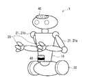
- FIG. 1 is a diagram showing a schematic configuration example of a moving body used in an information processing system of the present disclosure
- FIG. 1 It is a figure showing the article example installed in the external environment which is a measuring target in the information processing system of FIG. 2 is a diagram showing an example of a World coordinate system, a Robot coordinate system, and an environment coordinate system in the information processing system of FIG. 1;
- FIG. FIG. 4 is a diagram for explaining the terms of FIG. 3;
- FIG. 2 is a diagram showing an example of a World coordinate system, a Robot coordinate system, and an environment coordinate system in the information processing system of FIG. 1;
- FIG. 6 is a diagram for explaining terms in FIG. 5;
- FIG. 5 FIG.
- FIG. 2 is a diagram showing an example of a World coordinate system, a Robot coordinate system, and an environment coordinate system in the information processing system of FIG. 1;
- FIG. 8 is a diagram for explaining terms in FIG. 7;
- FIG. 2 is a diagram showing an example of a World coordinate system, a Robot coordinate system, and an environment coordinate system in the information processing system of FIG. 1;
- FIG. 9 is a diagram for explaining the terms of FIG. 8;
- FIG. 1 is a diagram illustrating an example of functional blocks of an information processing system according to an embodiment of the present disclosure;
- FIG. 12 is a diagram showing an example of an information processing procedure in the information processing system of FIG. 11;
- FIG. 12A and 12B are diagrams showing examples of articles installed in an external environment to be measured in the information processing system of FIG.
- FIG. 12A and 12B are diagrams showing examples of articles installed in an external environment to be measured in the information processing system of FIG. 11;
- FIG. 12A and 12B are diagrams showing examples of articles installed in an external environment to be measured in the information processing system of FIG. 11;
- FIG. 12 is a diagram showing a modified example of the functional blocks of the information processing system of FIG. 11;
- FIG. 12 is a diagram showing a modified example of the functional blocks of the information processing system of FIG. 11;
- Example 2 map integration using manipulator contact position information. Modification Modification A Example of touching multiple points at the same time Variation B Example of contacting multiple points in sequence Modification C (Figs. 13 to 16) An example of placing an article with a characteristic shape, stiffness or texture in the external environment Modification D (Fig. 17) Example of adjusting the posture of the robot
- FIG. 1 illustrates a schematic configuration example of a robot apparatus 1 used in an information processing system 1000 according to an embodiment of the present disclosure.
- the robot device 1 includes, for example, a main body 10, a contact sensor 20, two manipulators 21, a moving mechanism 30, and a non-contact sensor 40.
- the robot device 1 corresponds to a specific example of the "moving body" of the present disclosure.
- the two manipulators 21 correspond to one specific example of the "manipulator” of the present disclosure.
- the non-contact sensor 40 corresponds to a specific example of the "first sensor section" of the present disclosure.
- the main body 10 includes, for example, a power unit and a control unit of the robot device 1, and is a central part to which each part of the robot device 1 is attached.
- the control unit controls the contact sensor 20, the two manipulators 21, the moving mechanism 30 and the non-contact sensor 40 provided in the robot device 1.
- FIG. Body 10 may be shaped to simulate the upper human body, including the head, neck, and torso.
- Each manipulator 21 is, for example, an articulated robot arm attached to the main body 10 .
- One manipulator 21 is attached, for example, to the right shoulder of the main body 10 imitating the upper half of a human body.
- the other manipulator 21 is attached, for example, to the left shoulder of the main body 10 that simulates the upper half of a human body.
- the manipulator 21 may be composed of, for example, a link mechanism having joints at positions corresponding to human shoulders, elbows and wrists.
- the contact sensor 20 is, for example, a pressure sensor provided on an end effector (so-called effector) at the end of the manipulator 21 .
- the pressure sensor is capable of detecting changes in pressure input to the pressure sensor.
- the contact sensor 20 may be a vision-based tactile sensor or a force sensor.
- the contact sensor 20 can detect whether the end effector has come into contact with an object present in the surrounding environment, or the gripping force of the end effector on the object.
- the movement mechanism 30 is, for example, a part provided in the lower part of the main body 10 and responsible for movement of the robot device 1 .
- the moving mechanism 30 may be a two-wheeled or four-wheeled moving device, or a two-legged or four-legged moving device.
- the movement mechanism 30 may be a hover-type, propeller-type, or track-type movement device.
- the non-contact sensor 40 is, for example, a sensor that is provided on the main body 10 or the like and detects (senses) information about the environment (external environment) around the robot device 1 in a non-contact manner.
- the non-contact sensor 40 outputs sensor data obtained by sensing.
- An external environment that can be sensed by the non-contact sensor 40 corresponds to a specific example of the "first external environment" of the present disclosure.
- the non-contact sensor 40 is an imaging device such as a stereo camera, monocular camera, color camera, infrared camera, or polarization camera.
- the non-contact sensor 40 is an environment sensor for detecting weather or weather, a microphone for detecting voice, an ultrasonic sensor, a ToF (Time of Flight) sensor, or a LiDAR (Light Detection and Ranging) sensor. It may be a depth sensor.
- the non-contact sensor 40 may be a position sensor such as a GNSS (Global Navigation Satellite System) sensor.
- GNSS Global Navigation Satellite System
- the non-contact sensor 40 is an imaging device capable of capturing a color image, a depth sensor such as a LiDAR sensor capable of measuring the distance to the target, or capable of simultaneously acquiring the target image and the distance.
- RGBD Red, Green, Blue, Depth
- the robot apparatus 1 may be provided with an RGBD sensor on the head of the main body 10 and a LiDAR sensor on the body of the main body 10 .
- the robot device 1 includes, for example, a movement mechanism 30 that moves the robot device 1, and a manipulator 21 that includes an end effector that can act on objects existing in the surrounding environment. That is, the robot apparatus 1 may be a robot apparatus capable of autonomous action or movement. Such a robot apparatus 1 can act or move based on an instruction from a user or a voluntary trigger.
- the accuracy of positioning in the action or movement of the robot device 1 depends on the accuracy of recognition of the surrounding environment by the robot device 1 . Therefore, if the robot apparatus 1 can recognize the surrounding environment with higher accuracy, the robot apparatus 1 can act or move with higher accuracy.
- the positional accuracy of the robot device 1 within the environment recognized by the robot device 1 is improved.
- the robot device 1 when the contact sensor 20 contacts the object detected from the surrounding environment by the non-contact sensor 40 , the robot device 1 also detects the object with the contact sensor 20 . At this time, the robot device 1 can grasp the position of the contact sensor 20 provided on the end effector of the manipulator 21 with high accuracy by using the body model of the robot device 1 and the information about the posture. Therefore, the robot device 1 uses the information of the surrounding environment detected by the non-contact sensor 40 and the position information of the contact sensor 20 that contacts an object existing in the surrounding environment to determine the position of the robot device 1. It can be grasped with higher accuracy.
- the robot device 1 can specify the position of the robot device 1 with respect to the object with higher accuracy than indirect measurement by the non-contact sensor 40 by directly contacting the object with the contact sensor 20 . According to this, the robot device 1 can recognize its own position with respect to the surrounding environment with higher accuracy.
- the object represents a stationary object that exists in the environment around the robot device 1 and has a size that the robot device 1 can touch.
- FIG. 2 illustrates an example of an article installed in an external environment that is a measurement target in the information processing system 1000 according to an embodiment of the present disclosure.
- FIG. 2 exemplifies a bookshelf 2 and a non-contact sensor 50 as such articles.
- the non-contact sensor 50 corresponds to a specific example of the "second sensor section" of the present disclosure.
- a plurality of shelves are installed at predetermined intervals on the bookshelf 2, and each shelf has depth, and for example, books, boxes, cameras, and alarm clocks can be installed.
- the non-contact sensor 50 is, for example, a sensor that is provided on the bookshelf 2 or the like and detects information about the surrounding environment (external environment) including the depth of each shelf of the bookshelf 2 without contact.
- the non-contact sensor 50 outputs sensor data obtained by sensing.
- the external environment that can be sensed by the non-contact sensor 50 corresponds to a specific example of the "second external environment" of the present disclosure.
- the sensing area (external environment) of the non-contact sensor 50 includes at least part of the sensing area (external environment) of the non-contact sensor 40 of the robot device 1 .
- the bookshelf 2 (and the depth of each shelf of the bookshelf 2 ) is the sensing area (external environment) of the non-contact sensor 50 and also the sensing area (external environment) of the non-contact sensor 40 of the robot device 1 .
- a map obtained by sensing by the non-contact sensor 50 corresponds to a specific example of the "second map" of the present disclosure.
- a map obtained by sensing by the non-contact sensor 40 of the robot device 1 corresponds to a specific example of the "first map" of the present disclosure.
- the second map includes at least part of the first map.
- map information about the bookshelf 2 (and the depth of each shelf of the bookshelf 2) is included in the second map and is also included in the first map.
- the non-contact sensor 50 is an imaging device such as a stereo camera, monocular camera, color camera, infrared camera, or polarization camera.
- the non-contact sensor 50 may be an environmental sensor for detecting weather or the like, a microphone for detecting voice, or a depth sensor such as an ultrasonic sensor, a ToF sensor, or a LiDAR sensor.
- the non-contact sensor 50 may be a position sensor such as a GNSS sensor.
- the non-contact sensor 50 is an imaging device capable of capturing a color image, a depth sensor such as a LiDAR sensor capable of measuring the distance to the target, or capable of simultaneously acquiring the target image and the distance. RGBD sensor may be used.
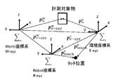
- the World coordinate system W-xyz is a coordinate system that serves as a reference for all coordinate systems.
- the Robot coordinate system R-xyz is the coordinate system of the robot device 1 that moves within the World coordinate system W-xyz.
- the origin of the Robot coordinate system R-xyz is, for example, at a predetermined location on the main body 10 .
- the environmental coordinate system E-xyz is a coordinate system whose origin is a predetermined point of a specific object (or article) in the World coordinate system W-xyz.
- FIG. 3 shows the World coordinate system W-xyz, the Robot coordinate system R-xyz, and the environment coordinate system E-xyz when the Robot coordinate system R-xyz matches the World coordinate system W-xyz. . That the Robot coordinate system R-xyz coincides with the World coordinate system W-xyz means that the robot apparatus 1 is stationary and does not move within the World coordinate system W-xyz.
- a robotic device performs manipulation using object coordinates p w 0 .
- the object coordinates p w 0 contain an error e w 0 due to a recognition error, as shown in equation (1) in FIG.
- the e w 0 hat included in equation (1) of FIG. 4 is the exact (true) value.
- the robot apparatus 1 does not use the object coordinates p w 0 .
- the robot device 1 estimates the position of the measurement object using the equation (2) in FIG. p w 0 estimate included in equation (2) in FIG. 4 is an estimated value.
- p w e-xyz included in equation (2) in FIG. 4 is a vector value from the origin of the World coordinate system W-xyz and the Robot coordinate system R-xyz to the origin of the environment coordinate system E-xyz.
- p e 0 included in equation (2) in FIG. 4 is a vector value from the origin of the environmental coordinate system E-xyz to the object to be measured.
- p w e ⁇ xyz and p e 0 include errors e w e ⁇ xyz and e w 0 due to recognition errors, as shown in equation (3) in FIG.
- the p w e-xyz and p e 0 hats included in equation (3) of FIG. 4 are exact (true) values.
- the distance from the robot device 1 to the non-contact sensor 50 is shorter than the distance from the robot device 1 to the object to be measured, and the non-contact sensor 50 arrangement There is a lot of freedom in places. In that case, since equation (4) in FIG. 4 holds true, it is important that equation (5) in FIG. 4 holds true.
- the error e w e-xyz included in p w e-xyz can be reduced by directly contacting the manipulator 21 of the robot apparatus 1 with the external environment.
- FIG. 5 shows the World coordinate system W-xyz, the Robot coordinate system R-xyz, and the environment coordinate system E-xyz when the Robot coordinate system R-xyz does not match the World coordinate system W-xyz. . That the Robot coordinate system R-xyz does not match the World coordinate system W-xyz means that the robot device 1 is moving within the World coordinate system W-xyz.
- the robot apparatus uses the object coordinates p w 0 and the self-position e w r ⁇ xyz , and finally performs manipulation with the object coordinates p w 0 as the target.
- the object coordinates p w 0 and the self-position e w r ⁇ xyz include errors e w 0 and e w r ⁇ xyz due to recognition errors, as shown in equation (6) in FIG. be
- the p w 0 hat and p w r-xyz hat included in equation (6) of FIG. 6 are exact (true) values.
- the robot apparatus 1 does not use the object coordinates p w 0 .
- the robot apparatus 1 estimates the position of the measurement object using equation (7) in FIG. p w 0 estimate included in equation (7) in FIG. 6 is an estimated value.
- p r e-xyz included in equation (7) in FIG. 6 is a vector value from the origin of the robot coordinate system R-xyz to the origin of the environment coordinate system E-xyz.
- p e 0 included in equation (7) in FIG. 6 is a vector value from the origin of the environmental coordinate system E-xyz to the object to be measured.
- p r e ⁇ xyz and p e 0 include errors e r e ⁇ xyz and e e 0 due to recognition errors, as shown in equation (8) in FIG.
- the p r e -xyz and p e 0 hats included in equation (8) of FIG. 6 are exact (true) values.
- the error e w r ⁇ xyz included in p w r ⁇ xyz can be estimated by the manipulator 21 directly touching the external environment.
- FIG. 7 shows each coordinate system when the manipulator 21 is brought into contact with the origin of the environmental coordinate system E-xyz.
- p r e-xyz is a vector from the origin of the robot coordinate system R-xyz to the touch position, which is recognized by the controller of the robot device 1. equal to p r touch .
- the vector p r touch and the vector p w e-xyz from the origin of the world coordinate system W-xyz to the touch position are both highly accurate values. Therefore, the controller of the robot apparatus 1 can obtain p w r-xyz with a small error e w r-xyz by using the equation (9) in FIG.
- FIG. 9 shows each coordinate system when the manipulator 21 is brought into contact with a position different from the origin of the environmental coordinate system E-xyz.
- p r e-xyz is equal to p r touch - p e touch .
- p e touch is a vector from the origin of the environmental coordinate system E-xyz to the touch position.
- the controller of the robot apparatus 1 can obtain p w r-xyz with a small error e w r-xyz by using the equation (10) in FIG.
- FIG. 11 shows an example of functional blocks of the information processing system 1000 .
- the information processing system 1000 includes an information processing device 100 provided in the robot device 1 and an information processing device 200 provided at a location different from the robot device 1 .
- the information processing device 100 and the information processing device 200 are communicably connected to each other by wireless communication, for example.
- Information processing apparatus 100 and information processing apparatus 200 may each include a communication unit that performs wireless communication using a wireless LAN or Bluetooth (registered trademark), for example.
- the information processing apparatus 100 includes, for example, an environment identification unit 110, a map information generation unit 120, a map information storage unit 130, a map information integration unit 140, a motion planning unit 150, a motion control unit 160, a contact detection unit 170, and a motion planning unit 180. and motion control unit 190 .
- the map information generator 120 corresponds to a specific example of the "first generator” of the present disclosure.
- the map information holding unit 130 corresponds to a specific example of the "first memory unit” of the present disclosure.
- the map information integration unit 140 corresponds to a specific example of the "integration unit” of the present disclosure.
- the exercise planning section 150 and the exercise control section 160 correspond to a specific example of the "control section" of the present disclosure.
- the entire information processing device 100 may be placed in the external environment. Only a part of the configuration of the information processing device 100 (for example, the environment identification section 110 and the motion control section 190) may be arranged in the external environment. At this time, the remaining components of the information processing apparatus 100 (for example, the map information generation unit 120, the map information holding unit 130, the map information integration unit 140, the motion planning unit 150, the motion control unit 160, the contact detection unit 170, and the motion planning unit 180) may be provided, for example, in a cloud server device.
- the map information generation unit 120, the map information holding unit 130, the map information integration unit 140, the motion planning unit 150, the motion control unit 160, the contact detection unit 170, and the motion planning unit 180 may be provided, for example, in a cloud server device.
- the information processing device 200 includes, for example, an environment identification unit 210, a map information generation unit 220, a map information storage unit 230, and a contact position detection unit 240.
- the entire information processing apparatus 200 may be arranged in the external environment.
- the map information generator 220 corresponds to a specific example of the "second generator” of the present disclosure.
- the map information holding unit 230 corresponds to a specific example of the "second memory unit” of the present disclosure.
- the contact position detection unit 240 corresponds to a specific example of the “position calculation unit” and “transmission unit” of the present disclosure.
- Only part of the information processing device 200 may be placed in the external environment. At this time, the rest of the information processing device 200 (for example, the map information generation unit 220 and the map information holding unit 230) may be provided in, for example, the cloud server device.
- the environment identification unit 110 includes a non-contact sensor 40.
- the environment identification unit 110 recognizes (senses) the external environment with the non-contact sensor 40, and generates recognition data Dr (sensing data) corresponding to the external environment through the recognition (sensing).
- the recognition data Dr is expressed in the robot coordinate system R-xyz.
- the environment identification section 110 outputs the generated recognition data Dr to the map information generation section 120 .
- the map information generation unit 120 processes the recognition data Dr input from the environment identification unit 110 based on the previous environment map Mr(t-1). The map information generator 120 further uses the processed recognition data Dr' to construct the environment map Mr(t) at the current time. The map information generator 120 stores the obtained environment map Mr(t) at the current time in the map information holder 130 .
- the map information holding unit 130 is composed of, for example, a volatile memory such as a DRAM (Dynamic Random Access Memory), or a non-volatile memory such as an EEPROM (Electrically Erasable Programmable Read-Only Memory) or flash memory.
- the map information holding unit 130 stores the environment map Mr.
- the environment map Mr is, for example, a map database including the current time environment map Mr(t) input from the map information generation unit 120 .
- the environment map Mr is represented by the robot coordinate system R-xyz.
- the motion planning unit 150 creates a motion plan for map integration based on the environment map Mr read from the map information holding unit 130 and the self-position data (current position data).
- the motion planning unit 150 moves the end effector, which is the terminal end of the manipulator 21, to the target position (touch position) based on the environment map Mr read from the map information holding unit 130 and the self position data (current position data). Create an exercise plan to get you there.
- the motion planning unit 150 determines, for example, what kind of path, direction and attitude of the manipulator 21 to move from the current position of the end of the manipulator 21 calculated from the self-position data (current position data). , the determination result is output to the motion control unit 160 as a motion plan.
- the motion control unit 160 generates a control signal for controlling the manipulator 21 based on the motion plan input from the motion planning unit 150 and outputs the control signal to the manipulator 21 . That is, the motion control unit 160 controls the motion of the manipulator 21 based on the environment map Mr.
- the manipulator 21 operates based on control signals input from the motion control section 160 .
- the end of the manipulator 21 reaches the target position (touch position), for example, the end effector of the manipulator 21 presses an object (or article) at the target position (touch position) with a predetermined pressure. .
- the contact detection unit 170 includes the contact sensor 20 provided on the end effector of the manipulator 21 .
- the contact detection unit 170 uses the contact sensor 20 to determine whether or not the end of the manipulator 21 has reached the target position (touch position).
- the contact detection unit 170 determines whether the terminal end of the manipulator 21 has reached the target position (touch position) based on detection data obtained from the contact sensor 20, for example.
- the contact detection unit 170 determines that the end of the manipulator 21 has reached the target position (touch position)
- it generates a signal (contact flag) indicating that.
- the contact detection unit 170 transmits the generated contact flag to the information processing device 200 via wireless communication.
- the map information integration unit 140 combines the environment map Mr and the environment map Me (described later) obtained from the information processing device 200 using position information (contact position information) in the external environment with which the terminal end of the manipulator 21 contacts. By integrating, an integrated map Mc is generated.
- the map information integration unit 140 acquires the contact position information of the terminal end of the manipulator 21 from the motion control unit 160 that controls the motion of the manipulator 21 .
- the map information integration unit 140 also acquires the contact position information of the terminal end of the manipulator 21 from the contact position detection unit 240 of the information processing device 200 .
- the contact position information of the terminal end of the manipulator 21 acquired from the motion control unit 160 that controls the operation of the manipulator 21 is referred to as first contact position information for convenience.
- the first contact position information is expressed in the robot coordinate system R-xyz and corresponds to the value of p r touch .
- the contact position information of the terminal end of the manipulator 21 obtained from the contact position detection unit 240 of the information processing device 200 is referred to as second contact position information for convenience.
- the second touch position information is expressed in the environmental coordinate system E-xyz and corresponds to the value of p e touch .
- the map information integration unit 140 derives the self-position p w r-xyz using, for example, equation (9) in FIG. 8 or equation (10) in FIG.
- the environment map Mr _ _ and an environment map Me (described later) obtained from the information processing apparatus 200 are integrated.
- the map information integration unit 140 generates the integrated map Mc.
- the map information integration unit 140 may store the generated integrated map Mc in the map information holding unit 130, for example.
- the exercise planning unit 180 uses the integrated map Mc read from the map information holding unit 130 to create an exercise plan.
- the integrated map Mc is generated, the end of the manipulator 21 is in contact with the object (or item) at the target position (touch position). That is, the integrated map Mc is used when controlling the operation of the manipulator 21 and the like while the end of the manipulator 21 is in contact with the object (or article) at the target position (touch position).
- the motion planning unit 180 creates a motion plan for executing a predetermined task based on the integrated map Mc generated by the map information integration unit 140 and self-position data (current position data).
- the predetermined task is, for example, an action of grabbing a predetermined object (eg, a camera placed on the bookshelf 2) in the external environment using a manipulator 21 different from the manipulator 21 that is in contact with the external environment.
- a manipulator 21 pointing to The manipulator 21 in contact with the external environment.
- manipulator 21a for convenience.
- the manipulator 21 different from the manipulator 21a is called “manipulator 21b".
- the motion control unit 190 generates a control signal for controlling the manipulator 21b based on the motion plan input from the motion planning unit 180, and outputs the control signal to the manipulator 21b.
- the manipulator 21b operates based on the control signal input from the motion control section 160.
- FIG. The manipulator 21b performs a predetermined task while the end of the manipulator 21a is in contact with the object (or article) at the target position (touch position).
- the environment identification unit 210 includes the non-contact sensor 50.
- the environment identification unit 210 recognizes (senses) the external environment using the non-contact sensor 50, and generates recognition data De corresponding to the external environment through the recognition (sensing).
- the recognition data De are expressed in the environmental coordinate system E-xyz.
- the environment identification section 210 outputs the generated recognition data De to the map information generation section 220 .
- the map information generation unit 220 processes the recognition data De input from the environment identification unit 210 based on the environment map Me(t-1) of the previous time.
- the map information generation unit 220 further uses the processed recognition data De' to construct the environment map Me(t) at the current time.
- the map information generating unit 220 stores the obtained environment map Me(t) at the current time in the map information holding unit 230 .
- the map information holding unit 230 is composed of, for example, a volatile memory such as DRAM, or a nonvolatile memory such as EEPROM or flash memory.
- the map information holding unit 230 stores the environment map Me.
- the environment map Me is, for example, a map database including the current time environment map Me(t) input from the map information generation unit 220 .
- the environmental map Me is represented by the environmental coordinate system E-xyz.
- the contact position detection unit 240 periodically acquires the environment map Me from the map information holding unit 230.
- the contact position detection unit 240 detects the contact position information (second contact position information) of the terminal end of the manipulator 21 included in the acquired environment map Me, that is, the manipulator 21 Calculate the contact position in the external environment of the end of the .
- the contact position detection unit 240 transmits the calculated second contact position information and the environment map Me to the map information integration unit 140 of the information processing device 100 .
- FIG. 12 shows an example of an information processing procedure in the information processing system 1000. As shown in FIG. 12
- the environment identification unit 110 performs recognition (sensing) of the external environment by the non-contact sensor 40 (step S101). Thereby, the environment identification unit 110 generates recognition data Dr (sensing data) corresponding to the external environment.
- the environment identification section 110 outputs the generated recognition data Dr to the map information generation section 120 .
- the map information generator 120 creates map information (environmental map Mr(t) at the current time) using the input recognition data Dr (step S102).
- the map information generator 120 stores the obtained map information (environmental map Mr(t) at the current time) in the map information holder 130 .
- the motion control unit 160 controls the motion of the manipulator 21 based on the environment map Mr(t) at the current time.
- the manipulator 21 operates based on the control signal input from the motion control unit 160 so that the terminal end of the manipulator 21 contacts the object (or article) at the target position (touch position).
- the environment identification unit 210 performs recognition (sensing) of the external environment by the non-contact sensor 50 (step S201). Thereby, the environment identification unit 210 generates recognition data De (sensing data) corresponding to the external environment. The environment identification section 210 outputs the generated recognition data De to the map information generation section 220 .
- the map information generator 220 creates map information (environmental map Me(t) at the current time) using the input recognition data De (step S202). The map information generator 220 stores the obtained map information (environmental map Me(t) at the current time) in the map information holder 230 .
- the contact detection unit 170 determines whether or not the terminal end of the manipulator 21 is in contact based on the detection data obtained from the contact sensor 20 (step S203). When the contact detection unit 170 determines that the end of the manipulator 21 is in contact, the contact detection unit 170 transmits a contact flag to the contact position detection unit 240 (step S203; Y, step S204). The contact position detection unit 240 determines whether or not the contact flag is input from the contact detection unit 170 (step S103). Upon detecting the input of the contact flag from the contact detection unit 170, the contact position detection unit 240 calculates the contact position of the terminal end of the manipulator 21 included in the environment map Me (step S103; Y, step S104). The contact position detection unit 240 transmits the calculated contact position and the environment map Me to the map information integration unit 140 (step S105).
- the map information integration unit 140 uses the contact position information acquired from the movement control unit 160 and the contact position information acquired from the contact position detection unit 240 to integrate the environment map Mr and the environment map Me to obtain an integrated map. Generate Mc.
- the map information integration unit 140 for example, generates the integrated map Mc while the end of the manipulator 21 is in contact with the object (or article) at the target position (touch position).
- the map information integration unit 140 thus updates the integrated map Mc (step S205).
- the motion planning unit 180 creates a motion plan for executing a predetermined task based on the integrated map Mc and the self-position data (current position data) (step S206).
- the motion control unit 190 controls the motion of the manipulator 21b based on the motion plan input from the motion planning unit 180 (step S206). As a result, manipulator 21b performs a predetermined task.
- the manipulator 21a is in contact with an object (or article) at the target position (touch position) during map integration by the map information integration unit 140 or while the manipulator 21b is executing a predetermined task. Thereby, the manipulator 21b can perform a predetermined task with high precision.
- the integrated map Mc is generated by integrating the environment map Mr and the environment map Me using positional information within the external environment with which the manipulator 21a is in contact. As a result, it is possible to precisely specify the corresponding points in the environment map Mr and the environment map Me, so that stable and rapid manipulation can be performed.
- the environment map Me is a map of the external environment including at least part of the external environment that can be sensed by the non-contact sensor 40 .
- the manipulator 21a touches a predetermined position in an environment that corresponds to both the external environment that can be sensed by the non-contact sensor 40 and the external environment that can be sensed by the non-contact sensor 50.
- FIG. As a result, using the contact position information ( p r touch ) acquired from the motion control unit 160 and the contact position information ( p e touch ) acquired from the contact position detection unit 240, p w r-xyz can be determined. As a result, it is possible to precisely specify the corresponding points in the environment map Mr and the environment map Me, so that the manipulation can be performed stably and quickly.
- the contact position of the manipulator 21a calculated using the environment map Me and the environment map Me are transmitted to the information processing apparatus 100.
- FIG. As a result, the environment map Mr and the environment map Me are integrated using the contact position of the manipulator 21a calculated using the environment map Me and the contact position of the manipulator 21a calculated using the environment map Ma. generates an integrated map Mc.
- Mc As a result, it is possible to precisely specify the corresponding points in the environment map Mr and the environment map Me, so that stable and rapid manipulation can be performed.
- the generated integrated map Mc may be stored in the map information holding unit 130 .
- the exercise planning section 180 can create an exercise plan using the integrated map Mc read from the map information holding section 130 .
- the environmental map Me is generated using sensor data obtained from the non-contact sensor 50 .
- the environment map Me can be generated using the non-contact sensor 50 in areas where the environment map is not prepared in advance.
- the environment map Me can be generated using the non-contact sensor 50 for closed areas such as the depth of each shelf of the bookshelf 2, for example.
- the robot apparatus 1 may include a plurality of manipulators 21a.
- the motion control section 160 outputs control signals to the plurality of manipulators 21a based on the motion planning input from the motion planning section 150.
- FIG. Each manipulator 21 a may simultaneously touch different target positions (touch positions) based on control signals input from the motion control section 160 .
- the robot device 1 may be provided with manipulators 21c that can come into contact with the external environment not only at the terminal end, but also at, for example, a portion corresponding to the elbow.
- the motion control section 160 outputs a control signal to the manipulator 21c based on the motion planning input from the motion planning section 150.
- FIG. The manipulator 21c may simultaneously touch different target positions (touch positions) based on the control signal input from the motion control section 160, for example, using the terminal end and the portion corresponding to the elbow.
- the map information integration unit 140 can generate the integrated map Mc based on the contact position information of a plurality of locations with high relative position accuracy.
- the map information integration unit 140 for example, generates the integrated map Mc while a plurality of manipulators 21a or 21c are in contact with a plurality of locations in the external environment at the same time.
- the motion control section 160 may sequentially output a plurality of control signals to the manipulator 21a based on the motion planning input from the motion planning section 150.
- the manipulator 21a may sequentially touch different target positions (touch positions) based on a plurality of sequentially input control signals.
- the map information integrating section 140 can generate the integrated map Mc based on contact position information of a plurality of locations with high relative position accuracy.
- the map information integration unit 140 for example, generates the integrated map Mc while the manipulator 21a sequentially contacts a plurality of locations in the external environment. As a result, it is possible to precisely specify the corresponding points in the environment map Mr and the environment map Me, so that stable and rapid manipulation can be performed.
- [Modification C] 13, 14, and 15 show examples of articles installed in an external environment, which are objects to be measured in the information processing system 1000 according to the above embodiment and its modification.
- FIG. 13 exemplifies a convex portion 61 having a characteristic shape in the external environment as such an article.
- the convex portion 61 has, for example, a rod-like shape that protrudes in the normal direction compared to the surroundings.
- the protrusion 61 is, for example, gripped by an end effector at the end of the manipulator 21a or pressed by an end effector at the end of the manipulator 21a. Whether the end effector grips the protrusion 61 or presses the protrusion 61 can be detected, for example, by a pressure sensor provided on the end effector.
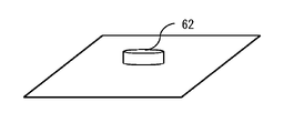
- FIG. 14 illustrates a sponge portion 62 having characteristic stiffness in the external environment.
- the sponge portion 62 is made of, for example, a sponge material that is softer than its surroundings.
- the sponge portion 62 is pressed by, for example, an end effector at the end of the manipulator 21a. Whether or not the end effector presses the sponge portion 62 can be detected by, for example, a pressure distribution sensor or a vision tactile sensor provided on the end effector.
- the vision-based tactile sensor is configured to detect changes in the surface shape of the end effector.
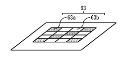
- FIG. 15 illustrates a textured portion 63 having a characteristic texture in the external environment.
- the textured portion 63 includes, for example, a plurality of rough surfaces 63a and a plurality of smooth surfaces 63b.
- a plurality of rough surfaces 63a and a plurality of smooth surfaces 63b are alternately arranged in a two-dimensional plane, as shown in FIG. 15, for example.
- the roughness of the textured portion 63 can be detected, for example, by a tactile sensor provided on the end effector at the end of the manipulator 21a.
- FIG. 16 shows an example of functional blocks of an information processing system 1000 according to this modified example.
- the information processing device 100 further has the texture detection section 310
- the information processing device 200 further has the contact detection section 320 .
- the contact detection unit 170 uses the contact sensor 20 to detect whether or not the end of the manipulator 21a is in contact.
- the contact detection unit 170 generates a contact flag and outputs it to the texture detection unit 310 when detecting contact with the end of the manipulator 21a.
- the texture detection unit 310 detects the physical characteristics (e.g., characteristic shape, stiffness or texture). Texture detection section 310 outputs the detection result (physical feature) to contact detection section 320 together with the contact flag.
- the environment map Me includes physical features of locations where the terminal end of the manipulator 21a comes into contact.
- the contact detection unit 320 compares physical features included in the environment map Me with detection results (physical features) input from the contact detection unit 170 . As a result, when both physical features match, the contact detection unit 320 determines that the end of the manipulator 21a is in contact with the expected contact position accurately, and sends a contact flag to the contact position detection unit 240. Output.
- the map information integration unit 140 generates the integrated map Mc while the manipulator 21a is in contact with a location having a characteristic shape, rigidity, or texture in the external environment, for example.
- the contact detection unit 320 determines that the terminal end of the manipulator 21a is in contact with a position different from the expected contact position, and applies a predetermined correction amount to the motion control unit. 160.
- a slight deviation in the contact position of the terminal end of the manipulator 21 can be corrected using the characteristic shape, rigidity or texture information of the contact point of the terminal end of the manipulator 21 .
- the contact position of the manipulator 21a can be detected with high accuracy, stable and rapid manipulation can be performed.
- FIG. 17 shows a modified example of functional blocks of the information processing system 1000 according to the above embodiment and its modified example.
- the information processing apparatus 100 further includes a posture adjustment section 330 .
- the attitude adjustment unit 330 adjusts the orientation of the manipulator 21a and the attitude of the main body 10 when the end of the manipulator 21a is in contact with the object (or article) at the target position (touch position).
- Posture adjustment section 330 calculates a correction amount necessary for the adjustment, and outputs the calculated correction amount to motion control section 160 .
- the contact sensor 20 provided at the end of the manipulator 21 may contact an area not shown on the environment map Mr, the environment map Me, or the environment map Mc. At this time, the coordinates of the terminal end of the manipulator 21 when the contact sensor 20 contacts some object (article) may be written in the environment map Mr. In this case, the robot apparatus 1 can update the environment map Mc using the contact sensor 20 even if the environment map Mc cannot be updated using the non-contact sensor 40 .
- the present disclosure can also be configured as follows. (1) a first information processing device provided in a mobile body; A second information processing device provided at a location different from the moving body, The first information processing device is a first sensor unit that senses a first external environment; a first generator that generates a first map using first sensor data obtained from the first sensor; a control unit that controls the operation of the manipulator based on the first map; An integrated map is created by integrating the first map and a second map obtained from the second information processing device using positional information within the first external environment with which the manipulator contacts.
- An information processing system comprising: a generating integrator; (2) the second map is a map of a second external environment including at least part of the first external environment; (1), wherein the integration unit generates the integrated map while the manipulator is in contact with a predetermined position within an environment corresponding to both the first external environment and the second external environment; information processing system.
- the second information processing device is a position calculation unit that calculates a contact position of the manipulator using the second map;
- the integration unit uses the contact position of the manipulator derived from the control information of the control unit and the contact position of the manipulator received from the second information processing device as position information in the first external environment where the manipulator contacts.
- the first information processing device has a first memory unit
- the second information processing device has a second memory unit storing the second map
- the information processing system according to any one of (1) to (4), wherein the integration unit stores the generated integrated map in the first memory unit.
- the second information processing device is a second sensor unit that senses the second external environment;
- the information processing system according to any one of (1) to (6), wherein the integration unit generates the integrated map while the manipulator sequentially contacts a plurality of locations within the first external environment.
- An information processing method comprising: generating an integrated map by: (11) (11), further comprising generating the integrated map while the manipulator is in contact with a predetermined position within an environment corresponding to both the first external environment and the second external environment. Information processing methods.
- (12) calculating a contact position of the manipulator using the second map;
- a contact position of the manipulator derived from control information for controlling the operation of the manipulator as position information in the first external environment with which the manipulator contacts; (12) further comprising generating the integrated map by integrating the first map and the second map using a correspondence relationship with the contact position of the manipulator received from an information processing device; Information processing method described.
- An information processing device provided in a mobile body, The information processing device is a first sensor unit that senses a first external environment; a first generator that generates a first map using first sensor data obtained from the first sensor; a control unit that controls the operation of the manipulator based on the first map; A second map obtained from a second information processing device provided at a location different from the first map and the moving object using position information in the first external environment with which the manipulator contacts.
- An information processing apparatus comprising: an integration unit that generates an integrated map by integrating
- the first map and the second map are displayed using the position information in the first external environment with which the manipulator contacts.
- An integrated map is generated by integrating. As a result, it is possible to accurately identify the corresponding locations in the first map and the second map. As a result, stable and rapid manipulation can be performed. Note that the effects of the present disclosure are not necessarily limited to the effects described herein, and may be any of the effects described herein.
Landscapes
- Engineering & Computer Science (AREA)
- Aviation & Aerospace Engineering (AREA)
- Radar, Positioning & Navigation (AREA)
- Remote Sensing (AREA)
- Physics & Mathematics (AREA)
- General Physics & Mathematics (AREA)
- Automation & Control Theory (AREA)
- Robotics (AREA)
- Mechanical Engineering (AREA)
- Human Computer Interaction (AREA)
- Manipulator (AREA)
Priority Applications (2)
| Application Number | Priority Date | Filing Date | Title |
|---|---|---|---|
| JP2023503620A JPWO2022185761A1 (https=) | 2021-03-04 | 2022-01-19 | |
| US18/547,361 US20240231383A9 (en) | 2021-03-04 | 2022-01-19 | Information processing system, information processing method, and information processing device |
Applications Claiming Priority (2)
| Application Number | Priority Date | Filing Date | Title |
|---|---|---|---|
| JP2021034824 | 2021-03-04 | ||
| JP2021-034824 | 2021-03-04 |
Publications (1)
| Publication Number | Publication Date |
|---|---|
| WO2022185761A1 true WO2022185761A1 (ja) | 2022-09-09 |
Family
ID=83155307
Family Applications (1)
| Application Number | Title | Priority Date | Filing Date |
|---|---|---|---|
| PCT/JP2022/001858 Ceased WO2022185761A1 (ja) | 2021-03-04 | 2022-01-19 | 情報処理システム、情報処理方法および情報処理装置 |
Country Status (3)
| Country | Link |
|---|---|
| US (1) | US20240231383A9 (https=) |
| JP (1) | JPWO2022185761A1 (https=) |
| WO (1) | WO2022185761A1 (https=) |
Citations (3)
| Publication number | Priority date | Publication date | Assignee | Title |
|---|---|---|---|---|
| JP2017136677A (ja) * | 2015-07-29 | 2017-08-10 | キヤノン株式会社 | 情報処理装置、情報処理方法、ロボット制御装置及びロボットシステム |
| JP2018501973A (ja) * | 2014-12-09 | 2018-01-25 | アイオロス ロボティクスAeolus Robotics | ロボット接触知覚 |
| WO2021033509A1 (ja) * | 2019-08-21 | 2021-02-25 | ソニー株式会社 | 情報処理装置、情報処理方法、及びプログラム |
Family Cites Families (5)
| Publication number | Priority date | Publication date | Assignee | Title |
|---|---|---|---|---|
| US10335951B2 (en) * | 2015-07-29 | 2019-07-02 | Canon Kabushiki Kaisha | Information processing apparatus, information processing method, robot control apparatus, and robot system |
| JP6849330B2 (ja) * | 2015-08-28 | 2021-03-24 | パナソニック インテレクチュアル プロパティ コーポレーション オブ アメリカPanasonic Intellectual Property Corporation of America | 地図生成方法、自己位置推定方法、ロボットシステム、およびロボット |
| US10596700B2 (en) * | 2016-09-16 | 2020-03-24 | Carbon Robotics, Inc. | System and calibration, registration, and training methods |
| DE102016125224A1 (de) * | 2016-12-21 | 2018-06-21 | Vorwerk & Co. Interholding Gmbh | Verfahren zur Navigation und Selbstlokalisierung eines sich autonom fortbewegenden Bearbeitungsgerätes |
| CN111770814A (zh) * | 2018-03-01 | 2020-10-13 | 多伦多大学管理委员会 | 校准移动机械手的方法 |
-
2022
- 2022-01-19 US US18/547,361 patent/US20240231383A9/en not_active Abandoned
- 2022-01-19 JP JP2023503620A patent/JPWO2022185761A1/ja not_active Abandoned
- 2022-01-19 WO PCT/JP2022/001858 patent/WO2022185761A1/ja not_active Ceased
Patent Citations (3)
| Publication number | Priority date | Publication date | Assignee | Title |
|---|---|---|---|---|
| JP2018501973A (ja) * | 2014-12-09 | 2018-01-25 | アイオロス ロボティクスAeolus Robotics | ロボット接触知覚 |
| JP2017136677A (ja) * | 2015-07-29 | 2017-08-10 | キヤノン株式会社 | 情報処理装置、情報処理方法、ロボット制御装置及びロボットシステム |
| WO2021033509A1 (ja) * | 2019-08-21 | 2021-02-25 | ソニー株式会社 | 情報処理装置、情報処理方法、及びプログラム |
Also Published As
| Publication number | Publication date |
|---|---|
| US20240231383A9 (en) | 2024-07-11 |
| US20240134390A1 (en) | 2024-04-25 |
| JPWO2022185761A1 (https=) | 2022-09-09 |
Similar Documents
| Publication | Publication Date | Title |
|---|---|---|
| JP7334239B2 (ja) | 拡張現実及びデジタルツインのためのロボット較正 | |
| US9844882B2 (en) | Conveyor robot system provided with three-dimensional sensor | |
| CN114800535B (zh) | 机器人的控制方法、机械臂控制方法、机器人及控制终端 | |
| JP6374984B2 (ja) | 定位面内にロボットを定位する方法 | |
| EP3862148A1 (en) | Information processing device, control method, and program | |
| WO2018043525A1 (ja) | ロボットシステム、ロボットシステム制御装置、およびロボットシステム制御方法 | |
| CN109313417A (zh) | 帮助机器人定位 | |
| JP2015199155A (ja) | 情報処理装置および情報処理方法、プログラム | |
| JP2012026895A (ja) | 位置姿勢計測装置、位置姿勢計測方法、およびプログラム | |
| WO2018043524A1 (ja) | ロボットシステム、ロボットシステム制御装置、およびロボットシステム制御方法 | |
| US20250196345A1 (en) | Dynamic and variable definition of robot missions | |
| WO2022014133A1 (ja) | モバイルマニピュレータ及びその制御方法及びプログラム | |
| CN110977959B (zh) | 控制装置、机器人、控制方法以及存储介质 | |
| Silva et al. | Navigation and obstacle avoidance: A case study using Pepper robot | |
| Lorentz et al. | Pointing gestures for human-robot interaction with the humanoid robot digit | |
| KR20200025749A (ko) | 외력의 측정을 위한 적어도 하나의 파라미터를 산출하는 방법 및 이를 수행하는 전자 장치 | |
| US20250196333A1 (en) | Robotic manipulation of objects | |
| US11496722B1 (en) | Systems and methods for automatically calibrating multiscopic image capture systems | |
| Chang et al. | Insert-one: One-shot robust visual-force servoing for novel object insertion with 6-dof tracking | |
| CN111837084A (zh) | 控制装置、控制方法和程序 | |
| Chen et al. | Human-aided robotic grasping | |
| JP2014087922A (ja) | ロボット制御装置及び方法 | |
| WO2022185761A1 (ja) | 情報処理システム、情報処理方法および情報処理装置 | |
| WO2021256464A1 (ja) | 撮像システム及びロボットシステム | |
| Haschke | Grasping and manipulation of unknown objects based on visual and tactile feedback |
Legal Events
| Date | Code | Title | Description |
|---|---|---|---|
| 121 | Ep: the epo has been informed by wipo that ep was designated in this application |
Ref document number: 22762820 Country of ref document: EP Kind code of ref document: A1 |
|
| WWE | Wipo information: entry into national phase |
Ref document number: 2023503620 Country of ref document: JP |
|
| WWE | Wipo information: entry into national phase |
Ref document number: 18547361 Country of ref document: US |
|
| NENP | Non-entry into the national phase |
Ref country code: DE |
|
| 122 | Ep: pct application non-entry in european phase |
Ref document number: 22762820 Country of ref document: EP Kind code of ref document: A1 |