WO2022185693A1 - Image processing device, radiographic imaging system, image processing method, and program - Google Patents
Image processing device, radiographic imaging system, image processing method, and program Download PDFInfo
- Publication number
- WO2022185693A1 WO2022185693A1 PCT/JP2021/048503 JP2021048503W WO2022185693A1 WO 2022185693 A1 WO2022185693 A1 WO 2022185693A1 JP 2021048503 W JP2021048503 W JP 2021048503W WO 2022185693 A1 WO2022185693 A1 WO 2022185693A1
- Authority
- WO
- WIPO (PCT)
- Prior art keywords
- image
- substance
- thickness
- energy
- image processing
- Prior art date
Links
- 238000012545 processing Methods 0.000 title claims abstract description 77
- 238000003384 imaging method Methods 0.000 title claims description 54
- 238000003672 processing method Methods 0.000 title claims description 5
- 239000000126 substance Substances 0.000 claims abstract description 123
- 230000005855 radiation Effects 0.000 claims abstract description 51
- 239000000463 material Substances 0.000 claims description 71
- 239000002872 contrast media Substances 0.000 claims description 50
- 210000000988 bone and bone Anatomy 0.000 claims description 42
- 238000000926 separation method Methods 0.000 claims description 26
- 238000004364 calculation method Methods 0.000 claims description 21
- 238000000034 method Methods 0.000 claims description 20
- 238000012937 correction Methods 0.000 claims description 13
- 210000001519 tissue Anatomy 0.000 claims description 5
- 230000009467 reduction Effects 0.000 claims description 4
- 238000001228 spectrum Methods 0.000 claims description 4
- ZCYVEMRRCGMTRW-UHFFFAOYSA-N 7553-56-2 Chemical compound [I] ZCYVEMRRCGMTRW-UHFFFAOYSA-N 0.000 claims description 3
- OYPRJOBELJOOCE-UHFFFAOYSA-N Calcium Chemical compound [Ca] OYPRJOBELJOOCE-UHFFFAOYSA-N 0.000 claims description 3
- 238000010521 absorption reaction Methods 0.000 claims description 3
- 229910052791 calcium Inorganic materials 0.000 claims description 3
- 239000011575 calcium Substances 0.000 claims description 3
- 229910052740 iodine Inorganic materials 0.000 claims description 3
- 239000011630 iodine Substances 0.000 claims description 3
- 229910052588 hydroxylapatite Inorganic materials 0.000 claims description 2
- 229910052751 metal Inorganic materials 0.000 claims description 2
- 239000002184 metal Substances 0.000 claims description 2
- XYJRXVWERLGGKC-UHFFFAOYSA-D pentacalcium;hydroxide;triphosphate Chemical compound [OH-].[Ca+2].[Ca+2].[Ca+2].[Ca+2].[Ca+2].[O-]P([O-])([O-])=O.[O-]P([O-])([O-])=O.[O-]P([O-])([O-])=O XYJRXVWERLGGKC-UHFFFAOYSA-D 0.000 claims description 2
- XLYOFNOQVPJJNP-UHFFFAOYSA-N water Substances O XLYOFNOQVPJJNP-UHFFFAOYSA-N 0.000 claims description 2
- 210000004872 soft tissue Anatomy 0.000 description 32
- 238000006243 chemical reaction Methods 0.000 description 19
- 238000010586 diagram Methods 0.000 description 17
- 239000003990 capacitor Substances 0.000 description 12
- 230000008859 change Effects 0.000 description 11
- 230000000630 rising effect Effects 0.000 description 10
- 238000005070 sampling Methods 0.000 description 10
- 230000035945 sensitivity Effects 0.000 description 10
- 210000003205 muscle Anatomy 0.000 description 4
- 230000008569 process Effects 0.000 description 4
- 238000003745 diagnosis Methods 0.000 description 3
- OAICVXFJPJFONN-UHFFFAOYSA-N Phosphorus Chemical compound [P] OAICVXFJPJFONN-UHFFFAOYSA-N 0.000 description 2
- 210000004204 blood vessel Anatomy 0.000 description 2
- 210000003127 knee Anatomy 0.000 description 2
- 230000003287 optical effect Effects 0.000 description 2
- 239000002245 particle Substances 0.000 description 2
- 229910004613 CdTe Inorganic materials 0.000 description 1
- 240000001973 Ficus microcarpa Species 0.000 description 1
- 238000002940 Newton-Raphson method Methods 0.000 description 1
- 208000009989 Posterior Leukoencephalopathy Syndrome Diseases 0.000 description 1
- 238000002083 X-ray spectrum Methods 0.000 description 1
- JJWKPURADFRFRB-UHFFFAOYSA-N carbonyl sulfide Chemical compound O=C=S JJWKPURADFRFRB-UHFFFAOYSA-N 0.000 description 1
- 230000001066 destructive effect Effects 0.000 description 1
- 238000005516 engineering process Methods 0.000 description 1
- 238000001914 filtration Methods 0.000 description 1
- 238000009499 grossing Methods 0.000 description 1
- 238000007689 inspection Methods 0.000 description 1
- 230000001678 irradiating effect Effects 0.000 description 1
- 238000005259 measurement Methods 0.000 description 1
- 150000002739 metals Chemical class 0.000 description 1
- 238000012986 modification Methods 0.000 description 1
- 230000004048 modification Effects 0.000 description 1
- 230000005258 radioactive decay Effects 0.000 description 1
- 238000002601 radiography Methods 0.000 description 1
- 230000000717 retained effect Effects 0.000 description 1
- 239000004065 semiconductor Substances 0.000 description 1
- 238000004088 simulation Methods 0.000 description 1
- 239000007779 soft material Substances 0.000 description 1
Images


Classifications
-
- G—PHYSICS
- G06—COMPUTING; CALCULATING OR COUNTING
- G06T—IMAGE DATA PROCESSING OR GENERATION, IN GENERAL
- G06T5/00—Image enhancement or restoration
- G06T5/50—Image enhancement or restoration by the use of more than one image, e.g. averaging, subtraction
-
- A—HUMAN NECESSITIES
- A61—MEDICAL OR VETERINARY SCIENCE; HYGIENE
- A61B—DIAGNOSIS; SURGERY; IDENTIFICATION
- A61B6/00—Apparatus for radiation diagnosis, e.g. combined with radiation therapy equipment
- A61B6/48—Diagnostic techniques
- A61B6/482—Diagnostic techniques involving multiple energy imaging
-
- A—HUMAN NECESSITIES
- A61—MEDICAL OR VETERINARY SCIENCE; HYGIENE
- A61B—DIAGNOSIS; SURGERY; IDENTIFICATION
- A61B6/00—Apparatus for radiation diagnosis, e.g. combined with radiation therapy equipment
- A61B6/52—Devices using data or image processing specially adapted for radiation diagnosis
- A61B6/5205—Devices using data or image processing specially adapted for radiation diagnosis involving processing of raw data to produce diagnostic data
-
- A—HUMAN NECESSITIES
- A61—MEDICAL OR VETERINARY SCIENCE; HYGIENE
- A61B—DIAGNOSIS; SURGERY; IDENTIFICATION
- A61B6/00—Apparatus for radiation diagnosis, e.g. combined with radiation therapy equipment
- A61B6/52—Devices using data or image processing specially adapted for radiation diagnosis
- A61B6/5211—Devices using data or image processing specially adapted for radiation diagnosis involving processing of medical diagnostic data
- A61B6/5217—Devices using data or image processing specially adapted for radiation diagnosis involving processing of medical diagnostic data extracting a diagnostic or physiological parameter from medical diagnostic data
-
- A—HUMAN NECESSITIES
- A61—MEDICAL OR VETERINARY SCIENCE; HYGIENE
- A61B—DIAGNOSIS; SURGERY; IDENTIFICATION
- A61B6/00—Apparatus for radiation diagnosis, e.g. combined with radiation therapy equipment
- A61B6/52—Devices using data or image processing specially adapted for radiation diagnosis
- A61B6/5258—Devices using data or image processing specially adapted for radiation diagnosis involving detection or reduction of artifacts or noise
-
- G—PHYSICS
- G01—MEASURING; TESTING
- G01N—INVESTIGATING OR ANALYSING MATERIALS BY DETERMINING THEIR CHEMICAL OR PHYSICAL PROPERTIES
- G01N23/00—Investigating or analysing materials by the use of wave or particle radiation, e.g. X-rays or neutrons, not covered by groups G01N3/00 – G01N17/00, G01N21/00 or G01N22/00
- G01N23/02—Investigating or analysing materials by the use of wave or particle radiation, e.g. X-rays or neutrons, not covered by groups G01N3/00 – G01N17/00, G01N21/00 or G01N22/00 by transmitting the radiation through the material
- G01N23/04—Investigating or analysing materials by the use of wave or particle radiation, e.g. X-rays or neutrons, not covered by groups G01N3/00 – G01N17/00, G01N21/00 or G01N22/00 by transmitting the radiation through the material and forming images of the material
-
- A—HUMAN NECESSITIES
- A61—MEDICAL OR VETERINARY SCIENCE; HYGIENE
- A61B—DIAGNOSIS; SURGERY; IDENTIFICATION
- A61B6/00—Apparatus for radiation diagnosis, e.g. combined with radiation therapy equipment
- A61B6/48—Diagnostic techniques
- A61B6/481—Diagnostic techniques involving the use of contrast agents
-
- A—HUMAN NECESSITIES
- A61—MEDICAL OR VETERINARY SCIENCE; HYGIENE
- A61B—DIAGNOSIS; SURGERY; IDENTIFICATION
- A61B6/00—Apparatus for radiation diagnosis, e.g. combined with radiation therapy equipment
- A61B6/52—Devices using data or image processing specially adapted for radiation diagnosis
- A61B6/5211—Devices using data or image processing specially adapted for radiation diagnosis involving processing of medical diagnostic data
- A61B6/5229—Devices using data or image processing specially adapted for radiation diagnosis involving processing of medical diagnostic data combining image data of a patient, e.g. combining a functional image with an anatomical image
- A61B6/5235—Devices using data or image processing specially adapted for radiation diagnosis involving processing of medical diagnostic data combining image data of a patient, e.g. combining a functional image with an anatomical image combining images from the same or different ionising radiation imaging techniques, e.g. PET and CT
-
- G—PHYSICS
- G06—COMPUTING; CALCULATING OR COUNTING
- G06T—IMAGE DATA PROCESSING OR GENERATION, IN GENERAL
- G06T2207/00—Indexing scheme for image analysis or image enhancement
- G06T2207/10—Image acquisition modality
- G06T2207/10116—X-ray image
-
- G—PHYSICS
- G06—COMPUTING; CALCULATING OR COUNTING
- G06T—IMAGE DATA PROCESSING OR GENERATION, IN GENERAL
- G06T2207/00—Indexing scheme for image analysis or image enhancement
- G06T2207/20—Special algorithmic details
- G06T2207/20212—Image combination
- G06T2207/20224—Image subtraction
-
- G—PHYSICS
- G06—COMPUTING; CALCULATING OR COUNTING
- G06T—IMAGE DATA PROCESSING OR GENERATION, IN GENERAL
- G06T2207/00—Indexing scheme for image analysis or image enhancement
- G06T2207/30—Subject of image; Context of image processing
- G06T2207/30004—Biomedical image processing
-
- G—PHYSICS
- G06—COMPUTING; CALCULATING OR COUNTING
- G06T—IMAGE DATA PROCESSING OR GENERATION, IN GENERAL
- G06T2207/00—Indexing scheme for image analysis or image enhancement
- G06T2207/30—Subject of image; Context of image processing
- G06T2207/30004—Biomedical image processing
- G06T2207/30101—Blood vessel; Artery; Vein; Vascular
Definitions
- the present invention relates to an image processing device, a radiation imaging system, an image processing method and a program. More specifically, the present invention relates to an image processing apparatus, a radiation imaging system, an image processing method, and a program that are preferably used for still image imaging such as general imaging in medical diagnosis and moving image imaging such as fluoroscopic imaging.
- radiation imaging devices using a flat panel detector (hereinafter abbreviated as "FPD") made of semiconductor materials are widely used as imaging devices for medical image diagnosis and non-destructive inspection using X-rays.
- FPD flat panel detector
- Such radiation imaging apparatuses are used, for example, in medical image diagnosis as digital imaging apparatuses for still image capturing such as general radiography and moving image capturing such as fluoroscopic imaging.
- One of the imaging methods using FPD is energy subtraction.
- energy subtraction a plurality of images corresponding to X-rays of different energies are acquired, and an image of a specific material (for example, a bone image and a soft tissue image) is obtained from the plurality of images by utilizing the difference in the X-ray attenuation rate of the material. tissue images) are separated.
- Japanese Patent Application Laid-Open No. 2002-200001 discloses a technique for improving the image quality of a bone image by smoothing an image of a soft tissue and subtracting the smoothed image from an accumulated image.
- the contrast of contrast agents and medical devices can change depending on the combination of X-ray image quality before separation. Therefore, when it is desired to emphasize a contrast agent or a medical device, it is preferable to acquire an X-ray image with a combination of tube voltages that maximizes the contrast.
- radiation imaging apparatuses may not be able to acquire X-ray images with the optimum tube voltage. Moreover, even if an image can be captured with the optimum tube voltage, a sufficient contrast may not be obtained.
- an object of the present invention is to acquire an image in which a predetermined substance is emphasized in a substance separation image.
- An image processing apparatus has the following configuration. That is, the image processing apparatus uses a plurality of images acquired with a first combination of radiation energies different from each other to obtain a first image showing the thickness of a first substance and a thickness of a second substance different from the first substance. and a third image showing the thickness of the first material and a fourth image showing the thickness of the second material using a plurality of images acquired with a second combination of different radiation energies. generating means for generating an image; and one of the first image and the second image, and one of the third image and the fourth image, the first substance and acquisition means for acquiring an enhanced image in which a third substance different from the second substance is emphasized.
- the present invention it is possible to acquire an image in which a predetermined substance is emphasized in a substance separation image. This makes it possible to provide an image with improved visibility of the contrast medium and the medical device.
- FIG. 1 is a diagram showing a configuration example of a radiation imaging system according to an embodiment
- FIG. FIG. 2 is an equivalent circuit diagram of pixels included in a two-dimensional detector of the X-ray imaging apparatus
- 4 is a timing chart showing operations for acquiring an X-ray image
- 4 is a diagram showing a processing flow of the image processing apparatus of the first embodiment
- FIG. FIG. 4 is a diagram showing an image example of a substance separation image
- FIG. 4 is a diagram showing the relationship between the combination of X-ray energies and the contrast
- FIG. 10 is a diagram showing an example of images when image calculation is performed on images of the same material.
- FIG. 7 is a diagram showing a processing flow of an image processing apparatus according to the second embodiment
- FIG. 10 is a diagram showing an example of images when image calculation is performed on images of different substances;
- Radiation in the present invention includes alpha rays, beta rays, gamma rays, etc., which are beams produced by particles (including photons) emitted by radioactive decay, as well as beams having energy equal to or higher than the same level, such as particle beams, Cosmic rays are also included.
- FIG. 1 is a block diagram showing a configuration example of a radiation imaging system 100 according to the first embodiment.
- a radiation imaging system 100 of the first embodiment includes an X-ray generation device 101 , an X-ray control device 102 , a control computer 103 and an X-ray imaging device 104 .
- the X-ray generator 101 emits X-rays.
- the X-ray controller 102 controls X-ray irradiation by the X-ray generator 101 .
- the control computer 103 controls the X-ray imaging device 104 to acquire a radiographic image (hereinafter referred to as an X-ray image (image information)) captured by the X-ray imaging device 104 .
- the control computer 103 functions as an image processing device that performs image processing, which will be described later, on an X-ray image acquired from the X-ray imaging device 104 .
- the X-ray imaging apparatus 104 may be provided with a function of executing image processing.
- the X-ray imaging device 104 is composed of a phosphor 105 that converts X-rays into visible light and a two-dimensional detector 106 that detects visible light.
- the two-dimensional detector 106 is a sensor in which pixels 20 for detecting X-ray quanta are arranged in an array of X columns ⁇ Y rows, and outputs image information.
- the control computer 103 has a CPU as a hardware configuration, and controls various operations of the control computer 103 by executing programs stored in an internal storage unit (ROM or RAM).
- the CPU of the control computer 103 controls X-ray irradiation by the X-ray control device 102 (X-ray generator 101 ) and X-ray image capturing operation by the X-ray imaging device 104 .
- the CPU also implements various signal processing and image processing, which will be described later. It should be noted that the operation of signal processing and image processing, which will be described later, may be partially or wholly realized by dedicated hardware.
- the internal storage unit stores programs executed by the CPU and various data, and stores radiation images (X-ray images) to be processed.
- a display (not shown) can be connected to the control computer 103, and the display displays images processed by image processing under the control of the CPU and performs various displays.
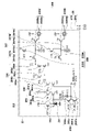
- FIG. 2 is an equivalent circuit diagram of the pixel 20 included in the two-dimensional detector 106.
- the pixel 20 includes a photoelectric conversion element 201 and an output circuit section 202 .
- Photoelectric conversion element 201 can typically be a photodiode.
- the output circuit section 202 includes an amplifier circuit section 204 , a clamp circuit section 206 , a sample hold circuit section 207 and a selection circuit section 208 .
- the photoelectric conversion element 201 includes a charge storage section, and the charge storage section is connected to the gate of the MOS transistor 204 a of the amplifier circuit section 204 .
- the source of MOS transistor 204a is connected to current source 204c through MOS transistor 204b.
- a source follower circuit is formed by the MOS transistor 204a and the current source 204c.
- the MOS transistor 204b is an enable switch that turns on when the enable signal EN supplied to its gate becomes active level to put the source follower circuit into operation.
- the charge-voltage converter is connected to reset potential Vres through reset switch 203 . When the reset signal PRES becomes active level, the reset switch 203 is turned on, and the potential of the charge-voltage converter is reset to the reset potential Vres.
- the clamp circuit section 206 clamps the noise output by the amplifier circuit section 204 according to the reset potential of the charge-voltage conversion section with the clamp capacitor 206a.
- the clamp circuit unit 206 is a circuit for canceling this noise from the signal output from the source follower circuit according to the charge generated by photoelectric conversion in the photoelectric conversion element 201 .
- This noise includes kTC noise at reset. Clamping is performed by setting the clamp signal PCL to the active level to turn on the MOS transistor 206b and then setting the clamp signal PCL to the inactive level to turn off the MOS transistor 206b.
- the output side of the clamp capacitor 206a is connected to the gate of the MOS transistor 206c.
- MOS transistor 206c The source of MOS transistor 206c is connected to current source 206e through MOS transistor 206d.
- a source follower circuit is formed by the MOS transistor 206c and the current source 206e.
- the MOS transistor 206d is an enable switch that turns on when the enable signal EN0 supplied to its gate becomes active level to put the source follower circuit into operation.
- a signal output from the clamp circuit unit 206 according to the charge generated by photoelectric conversion in the photoelectric conversion element 201 is written as a light signal into the capacitor 207Sb via the switch 207Sa when the light signal sampling signal TS becomes active level.
- the signal output from the clamp circuit section 206 when the MOS transistor 206b is turned on immediately after resetting the potential of the charge-voltage conversion section is the clamp voltage.
- This noise signal is written into the capacitor 207Nb through the switch 207Na when the noise sampling signal TN becomes active level.
- This noise signal contains the offset component of the clamp circuit section 206 .
- a switch 207Sa and a capacitor 207Sb constitute a signal sample and hold circuit 207S
- a switch 207Na and a capacitor 207Nb constitute a noise sample and hold circuit 207N.
- the sample and hold circuit section 207 includes a signal sample and hold circuit 207S and a noise sample and hold circuit 207N.
- the drive circuit drives the row selection signal to the active level
- the signal (light signal) held in the capacitor 207Sb is output to the signal line 21S via the MOS transistor 208Sa and the row selection switch 208Sb.
- the signal (noise) held in capacitor 207Nb is output to signal line 21N via MOS transistor 208Na and row select switch 208Nb.
- the MOS transistor 208Sa forms a source follower circuit with a constant current source (not shown) provided on the signal line 21S.
- the MOS transistor 208Na forms a source follower circuit with a constant current source (not shown) provided on the signal line 21N.
- a signal selection circuit portion 208S is composed of the MOS transistor 208Sa and the row selection switch 208Sb
- a noise selection circuit portion 208N is composed of the MOS transistor 208Na and the row selection switch 208Nb.
- the selection circuit section 208 includes a signal selection circuit section 208S and a noise selection circuit section 208N.
- the pixel 20 may have an addition switch 209S that adds the optical signals of a plurality of adjacent pixels 20.
- the addition mode signal ADD becomes active level and the addition switch 209S is turned on.
- the capacitors 207Sb of adjacent pixels 20 are connected to each other by the addition switch 209S, and the optical signals are averaged.
- pixel 20 may have a summing switch 209N that sums the noise of adjacent pixels 20 .
- Addition section 209 includes an addition switch 209S and an addition switch 209N.
- the pixel 20 may have a sensitivity changing section 205 for changing sensitivity.
- the pixel 20 can include, for example, a first sensitivity change switch 205a and a second sensitivity change switch 205'a and their associated circuit elements.
- the first change signal WIDE becomes active level
- the first sensitivity change switch 205a is turned on, and the capacitance value of the first additional capacitor 205b is added to the capacitance value of the charge-voltage converter. This reduces the sensitivity of the pixel 20 .
- the second change signal WIDE2 becomes active level
- the second sensitivity change switch 205'a is turned on, and the capacitance value of the second additional capacitor 205'b is added to the capacitance value of the charge-voltage converter.
- the enable signal ENw may be made the active level to cause the MOS transistor 204'a to perform the source follower operation instead of the MOS transistor 204a.
- the X-ray imaging apparatus 104 reads the output of the pixel circuit as described above, converts it into a digital value with an AD converter (not shown), and then transfers the image to the control computer 103 .
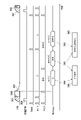
- FIG. 3 is a diagram showing drive timings when energy subtraction is performed in the radiation imaging system 100.
- the horizontal axis represents time, and the timings of X-ray irradiation, synchronization signals, resetting of the photoelectric conversion element 201 , sample hold circuit 207 and image reading from the signal line 21 are shown.
- the photoelectric conversion element 201 is reset, and then X-rays are emitted.
- the X-ray tube voltage ideally becomes a rectangular wave, it takes a finite amount of time for the tube voltage to rise and fall.
- the tube voltage can no longer be regarded as a rectangular wave, and has a waveform as shown in FIG. That is, the energy of X-rays differs in the rising period, the stable period, and the falling period of X-rays.
- sampling is performed by the noise sample-and-hold circuit 207N after the X-rays 301 in the rising period are emitted, and sampling is performed by the signal sample-and-hold circuit 207S after the X-rays 302 in the stable period are emitted.
- the difference between the signal lines 21N and 21S is read out as an image.
- the noise sample-and-hold circuit 207N holds the signal (G) of the X-ray 301 in the rising period
- the signal sample-and-hold circuit 207S holds the signal of the X-ray 301 in the rising period and the signal of the X-ray 302 in the stable period.
- the sum (B+G) is retained. Therefore, an image 304 corresponding to the signal (B) of the X-rays 302 in the stable period is read out from the X-ray imaging apparatus 104 .
- the noise sample-and-hold circuit 207N holds the signal (G) of the X-ray 301 in the rising period
- the signal sample-and-hold circuit 207S holds the signal of the X-ray 301 in the rising period, the X-ray 302 in the stable period and the falling edge.
- the sum (B+R+G) of the signals of the X-rays 303 in the period is held.
- an image 306 corresponding to the signal (B) of the X-rays 302 in the stable period and the signal (R) of the X-rays 303 in the falling period is read out from the X-ray imaging apparatus 104 .
- the photoelectric conversion element 201 is reset, sampling is performed again by the noise sample hold circuit 207N, and the difference between the signal lines 21N and 21S is read out as an image.
- the noise sample-and-hold circuit 207N holds the signal in the state where no X-ray is emitted
- the signal sample-and-hold circuit 207S holds the signal of the X-ray 301 in the rising period, the X-ray 302 in the stable period, and the signal of the falling edge.
- the sum (B+R+G) of the signals of the X-rays 303 in the period is held.
- an image 308 corresponding to the signal (G) of the X-rays 301 in the rising period, the signal (B) of the X-rays 302 in the stable period, and the signal (R) of the X-rays 303 in the falling period is read out.
- an image 305 corresponding to the signal (R) of the X-ray 303 in the fall period is obtained.
- an image 307 corresponding to the signal (G) of the X-ray 301 in the rising period is obtained.
- the timing for resetting the sample hold circuit 207 and the photoelectric conversion element 201 is determined using the synchronization signal 309 indicating that the X-ray generator 101 has started X-ray irradiation.
- a method for detecting the start of X-ray irradiation a configuration that measures the tube current of the X-ray generator 101 and determines whether or not the current value exceeds a preset threshold value is preferably used.
- the pixel 20 is repeatedly read out, and a configuration in which it is determined whether or not the pixel value exceeds a preset threshold value is preferably used. Furthermore, a configuration in which an X-ray detector different from the two-dimensional detector 106 is incorporated in the X-ray imaging apparatus 104 and whether or not the measured value exceeds a preset threshold is preferably used. In either method, the signal sample-and-hold circuit 207S is sampled, the noise sample-and-hold circuit 207N is sampled, and the photoelectric conversion element 201 is reset after a predetermined time has elapsed since the synchronization signal 309 was input.
- an image 304 (corresponding to the signal (B)) corresponding to the stable period of the pulse X-ray
- an image 306 corresponding to the signal (B+R)
- An image 308 corresponding to signal (B+R+G)) corresponding to the sum of rising, stable and falling periods is obtained. Since the energies of the X-rays irradiated when forming the three images are different, energy subtraction processing can be performed by performing calculations between the images.
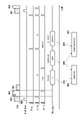
- FIG. 4 shows drive timing when energy subtraction is performed in the radiation imaging system 100 according to the first embodiment.
- the driving timing shown in FIG. 4 differs from the driving timing shown in FIG. 3 in that the X-ray tube voltage is actively switched.
- the photoelectric conversion element 201 is reset, and then medium-energy X-rays 401 are emitted. After that, sampling is performed by the noise sample-and-hold circuit 207N, and after the tube voltage is switched and the high-energy X-ray 402 is emitted, sampling is performed by the signal sample-and-hold circuit 207S. Thereafter, the tube voltage is switched to irradiate low-energy X-rays 403 . Furthermore, the difference between the signal lines 21N and 21S is read out as an image.
- the signal (G) of the intermediate energy X-ray 401 is held in the noise sample hold circuit 207N, and the signal (G) of the intermediate energy X-ray 401 and the high energy X-ray 402 are held in the signal sample hold circuit 207S.
- the sum (B+G) of the signals (B) of is held. Therefore, an image 404 corresponding to the signal (B) of high-energy X-rays 402 is read out from the X-ray imaging apparatus 104 .
- the photoelectric conversion element 201 is reset, sampling is performed again by the noise sample hold circuit 207N, and the difference between the signal lines 21N and 21S is read out as an image.
- the noise sample-and-hold circuit 207N holds a signal in a state in which no X-rays are emitted
- the signal sample-and-hold circuit 207S holds the signal (G) of the medium-energy X-ray 401 and the signal (G) of the high-energy X-ray.
- the sum (B+R+G) of the signal (B) of 402 and the signal (R) of the low-energy X-ray 403 is held.
- an image 408 corresponding to the signal (G) of medium-energy X-rays 401, the signal (B) of high-energy X-rays 402, and the signal (R) of low-energy X-rays 403 is read out.
- Synchronization signal 409 is the same as in FIG. In this way, by acquiring images while actively switching the tube voltage, the energy difference between X-ray images can be increased more than in the method of FIG. Note that the order of X-ray energies can be changed.
- X-ray 401 may be low energy, X-ray 402 high energy, and X-ray 403 medium energy.
- the control computer 103 acquires a radiation image (X-ray image (image information)) captured by the X-ray imaging device 104 .
- the control computer 103 performs various processes on the X-ray image acquired from the X-ray imaging device 104 .
- the energy subtraction processing in this embodiment is divided into three stages of correction processing, signal processing, and image processing. Processing at each stage will be described below.
- an image is acquired without irradiating the X-ray imaging device 104 with X-rays.
- This image is an image corresponding to the fixed pattern noise (FPN) of the X-ray imaging apparatus 104, and the fixed pattern noise (FPN) component is removed by subtracting the component of this image.
- FPN fixed pattern noise
- X-rays are emitted to the X-ray imaging device 104 in the absence of a subject to perform imaging, and an image (X-ray image) is acquired by the driving shown in FIGS. 3 and 4 .
- An image (white image) obtained by offset-correcting the X-ray image is prepared, and the X-ray image is divided by the white image, thereby uniformly correcting variations in characteristics such as the sensitivity of the pixels 20 .
- This correction is called white correction.
- the image after the white correction has an attenuation rate of I/ I0 .
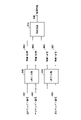
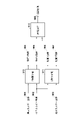
- FIG. 5 is a diagram showing the processing flow of the image processing apparatus of the first embodiment.
- the control computer 103 generates a first image (hereinafter referred to as a material 1 image 504) showing the thickness of the first material separated from a plurality of images (501, 502) acquired with a first combination of radiation energies different from each other, and a first image A second image (hereinafter referred to as material 2 image 505) showing the thickness of the two materials is generated.
- the control computer 103 also generates a third image (hereinafter referred to as a material 1 image '506) showing the thickness of the first material separated from the plurality of images (502, 503) acquired with the second combination of different radiation energies. ) and a fourth image showing the thickness of the second material (hereinafter referred to as material 2 image '507).
- the plurality of images acquired with a first combination of radiation energies different from each other includes an image captured with the first energy (hereinafter referred to as a high energy image 501) and a second energy captured with a second energy lower than the first energy. image (hereinafter medium energy image 502).
- the plurality of images acquired with the second combination of radiation energies different from each other includes an image captured with the second energy (medium energy image 502) and a third energy captured with a third energy lower than the second energy. image (hereinafter referred to as low energy image 503).
- a high-energy image 501, a medium-energy image 502, and a low-energy image 503 are images after performing offset correction and white correction on the X-ray images obtained by the driving shown in FIGS.
- thickness images of a first substance (hereinafter referred to as “substance 1”) and a second substance (hereinafter referred to as “substance 2”) are obtained from two images with different energies.
- the image H the one with the higher energy
- the one with the lower energy is called the image L.
- FIG. A case will be described in which the thickness image S of the soft tissue and the thickness image B of the bone are obtained, with the substances 1 and 2 as soft tissue and bone.
- ⁇ S (E) is the linear attenuation coefficient of soft tissue at energy E
- ⁇ B (E) is the linear attenuation coefficient of bone at energy E
- NH (E) is the spectrum for high-energy X-rays
- NH (E) is for low-energy X-rays.
- X-ray spectra N H (E) and N L (E) can be obtained by simulation or actual measurement.
- the linear attenuation coefficient ⁇ B (E) of bone at energy E and the linear attenuation coefficient ⁇ S (E) of soft tissue at energy E can be obtained from databases such as NIST (National Institute of Standards and Technology).
- NIST National Institute of Standards and Technology
- the Newton-Raphson method may be used, or an iterative method such as the least-squares method or the bisection method may be used.
- the soft tissue thickness S and the bone thickness B for various combinations of high energy attenuation rate H and low energy attenuation rate L are obtained in advance to generate a table, and by referring to the table, the thickness of the soft tissue A configuration for obtaining S and the thickness B of the bone at high speed may be used.
- a material 1 image 504 and a material 2 image 505 are material separation images obtained by separating the high energy image 501 and the medium energy image 502 into two materials.
- a material 1 image '506 and a material 2 image' 507 are material separation images obtained by separating the medium energy image 502 and the low energy image 503 into two materials.
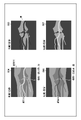
- FIG. 6 is a diagram showing an image example of a substance separation image, showing image examples of a substance 1 image 504, a substance 2 image 505, a substance 1 image '506, and a substance 2 image '507.
- the object is the lower leg (knee), and the blood vessel is in a state in which the contrast medium is injected.
- An image contains three substances: soft substances (soft tissue) such as muscle and fat, bones, and a contrast agent.
- the material 1 image 504 and material 1 image '506 are soft tissue thickness images
- the material 2 image 505 and material 2 image '507 are bone thickness images. Muscle and fat appear only in soft tissue thickness images, and bone appears only in bone thickness images. In contrast, the contrast agent appears in both the soft tissue thickness image and the bone thickness image.
- the attenuation coefficient of the contrast agent which is the third substance (hereinafter referred to as “substance 3”), is not included in the [Formula 1] formula, and is converted into the thickness of the soft tissue and the thickness of the bone at a constant rate (depending on the X-ray energy) It does not appear only in one side because it is The reason why the bone contrast appears in the thickness image of the soft tissue is that there is a reduction in the thickness of the bone. If the two-substance separation is performed with high accuracy, the contrast agent Areas without , the values match. On the other hand, contrast agent areas do not match in value. This is because when the X-ray energy is changed, the ratio of the thickness of the contrast agent converted to the thickness of the soft substance and the thickness of the bone changes. Note that depending on the energy, the thickness of the region of the contrast medium can take a negative value.
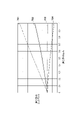
- FIG. 7 is a diagram showing the relationship between the combination of X-ray energies and the contrast, and shows a graph relating to the contrast of the contrast agent in the thickness image of the substance 1 obtained by changing the combination of the X-ray energies.
- the horizontal axis of the graph is the thickness of the contrast agent, and the vertical axis is the contrast of the contrast agent.
- FIG. 8 is a diagram showing an example of images when image calculation is performed on images of the same material.
- a combination 704 (second combination) acquires a substance 1 image 504 and a substance 1 image '506 as substance separation images, and an image example obtained by performing image calculation 512 is shown.
- material 1 image 504 and material 1 image '506 are soft tissue thickness images
- control computer 103 performs image operation 512 to subtract image information based on material 1 image 504 and material 1 image '506. to obtain a contrast-enhanced image 801 (enhanced image 508 (FIG. 5)) of substance 3 (contrast agent).
- Image 801 is different in positive and negative of the contrast of the contrast agent between the substance 1 image 504 and the substance 1 image '506 (white in 504 in FIG. 6, black in 506). contrast is emphasized (increased). In addition, since the thickness of the substance 1 (soft tissue) is canceled between the substance 1 image 504 and the substance 1 image '506, only the contrast medium can be seen (if it is performed with moving images, maskless DSA can be achieved). Therefore, the contrast of the contrast agent is enhanced, and soft tissue and bony structures are removed, which may improve visibility. Image calculation 512 enhances the contrast of substance 3 (contrast agent), and an image 801 from which soft tissues and bones have been removed can be obtained.
- substance 3 contrast agent
- the process of performing image calculations between images of the same substance is not limited to this example, and the image calculation 512 is performed on the bone thickness image based on the substance 2 image 505 and the substance 2 image '507. It is also possible to Also in this case, the contrast of substance 3 (contrast agent) can be enhanced, and an image 801 with soft tissues and bones removed can be obtained.
- substance 3 contrast agent
- FIG. 9 is a diagram showing the processing flow of the image processing apparatus of the second embodiment.
- the control computer 103 generates a first image (hereinafter referred to as a material 1 image 904) showing the thickness of a first material separated from a plurality of images (901, 902) acquired with a first combination of radiation energies different from each other, and a first image A second image (hereinafter referred to as material 2 image 905) showing the thickness of the two materials is generated.
- the control computer 103 also generates a third image (hereinafter referred to as a material 1 image 906) showing the thickness of the first material separated from the plurality of images (902, 903) acquired with the second combination of different radiation energies. ) and a fourth image showing the thickness of the second material (hereinafter, material 2 image '907).
- the plurality of images acquired with the first combination of radiation energies different from each other includes an image captured with the first energy (hereinafter referred to as a high energy image 901) and a second energy lower than the first energy. contains an image taken at (hereafter medium energy image 902).
- the plurality of images acquired with the second combination of radiation energies different from each other includes an image captured with the second energy (medium energy image 902) and a third energy captured with a third energy lower than the second energy. image (hereinafter referred to as low energy image 903).
- a high-energy image 901, a medium-energy image 902, and a low-energy image 903 are images after performing offset correction and white correction on the X-ray images acquired by the driving shown in FIGS.
- thickness images of material 1 (904, 906) and thickness images of material 2 (905, 907) are obtained from the two images at different energies.
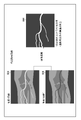
- FIG. 10 is a diagram showing an example of images when performing image calculations on images of different substances.
- the subject is the lower leg (knee), and the blood vessel is in a state in which the contrast agent is injected.
- An image contains three substances: soft substances (soft tissue) such as muscle and fat, bones, and a contrast agent.
- soft substances soft tissue
- the material 1 image 904 and material 1 image '906 are soft tissue thickness images
- the material 2 image 905 and material 2 image '907 are bone thickness images. Muscle and fat appear only in soft tissue thickness images, and bone appears only in bone thickness images.
- the contrast agent appears in both the soft tissue thickness image and the bone thickness image.
- the attenuation coefficient of the contrast medium which is Substance 3, is not included in [Equation 1] and is converted into the thickness of the soft tissue and the thickness of the bone at a constant ratio (depending on the energy of the X-ray), so it cannot appear in only one of them. do not have.
- the reason why the bone contrast appears in the thickness image of the soft tissue is that there is a reduction in the thickness of the bone. If the two-substance separation is performed with high accuracy, the contrast agent Areas without , the values match. On the other hand, contrast agent areas do not match in value. This is because when the X-ray energy is changed, the ratio of the thickness of the contrast agent converted to the thickness of the soft substance and the thickness of the bone changes. Note that depending on the energy, the thickness of the region of the contrast medium can take a negative value.
- the thickness image of substance 1 and the thickness image of substance 2 it is possible to remove the bone structure in the soft substance and improve the visibility of the contrast agent (bone backfill image).
- the thickness of the contrast agent is converted into the thickness of the soft tissue and the thickness of the bone at a fixed ratio. That is, the thicker the material image, the thinner the other image. Therefore, even if the thickness image of substance 1 and the thickness image of substance 2 are added, there is a possibility that sufficient contrast cannot be obtained with respect to the background substance (addition of contrast black and white). Therefore, in the present embodiment, images in which the thickness of the contrast agent is large or images in which the thickness of the contrast agent is small are added.
- control computer 103 adds the image information of the substance 1 image 904 and the substance 2 image 907 (addition of contrast white and white), or adds the image information of the substance 2 image 905 and the substance 1 image 906 (contrast black). black addition) to acquire a contrast-enhanced image 1001 (enhanced image 908 (FIG. 9)) of substance 3 (contrast agent).
- An image 1001 shown in FIG. 10 shows an example of an image when the substance 2 image 905 and the substance 1 image 906 are added.
- the thickness image before processing by the image calculation 912 is The contrast of the contrast agent is enhanced (higher) than Also, by adding the material 2 image 905 (bone) and the material 1 image 906 (soft tissue), the thickness of material 2 (bone) is backfilled, so only the continuous thickness of the soft tissue and the contrast agent are visible. . Therefore, the contrast of the contrast agent is enhanced and the bone structure is removed, which may improve visibility.
- Image operation 912 enhances the contrast of material 3 (contrast agent) and allows obtaining image 1001 with bone removed.
- the control computer 103 obtains a plurality of images (501 and 502, 901 and 902) acquired with the first combination of radiation energies by performing a plurality of sample-holds during one shot of radiation exposure. The resulting images are acquired to generate a first image (material 1 image 504, 904) and a second image (material 2 image 505, 905).
- control computer 103 performs a plurality of sample-holds during exposure of one shot of radiation as a plurality of images (502 and 503, 902 and 903) acquired with the second combination of radiation energies.
- the images obtained by the above are acquired to generate a third image (substance 1 image '506, 906) and a fourth image (substance 2 image '507, 907).
- the control computer 103 can perform display control for moving image display or real-time display on the display unit of the emphasized image obtained by computing the image information based on the generated image.
- the first material comprises at least water or a soft material free of fat or calcium
- the second material comprises at least calcium, hydroxyapatite, or bone.
- the third substance (substance 3) is a contrast agent. It is also applicable to substances (materials) containing metals.
- Noise may be reduced by filtering using a spatial filter when calculating the thickness image.
- the control computer 103 can perform noise reduction processing by applying a spatial filter to the thickness image used for calculation before calculating the image information.
- control computer 103 can perform image processing for removing the component of the predetermined tissue included in the thickness image by multiplying the thickness image used for the calculation by the correction coefficient. .
- control computer 103 can perform display control and image processing for emphasizing the component of a predetermined tissue included in the thickness image used for the image calculation and displaying it on the display unit before calculating the image information. It is possible.
- a combination of X-ray energies for example, combinations 701 and 704 in FIG. 7 that increases the contrast of the contrast agent in the image after subtracting the thickness image.
- threshold determination may be performed to determine the presence or absence of the contrast medium, and the region of the contrast medium may be enhanced by image processing.
- the control computer 103 determines the region where the contrast agent (third substance) exists based on whether the pixel values of the contrast-enhanced images 801 and 1001 (enhanced images) exceed a preset threshold.
- image processing for emphasizing and displaying on the display unit an area in which is present.
- the area enhancement for example, the area corresponding to the contrast agent may be colored and highlighted. Alternatively, the pixel values of the region corresponding to the contrast medium may be fixed to a specific value and highlighted.
- Enhancement by image processing is not limited to the images 801 and 1001 after contrast enhancement, and can be applied to any of X-ray images, thickness images, and thickness images after calculation.
- the control computer 103 determines that a region having different thicknesses among the plurality of thickness images used for image information calculation (image calculation 512, 912) is a region in which a contrast agent (third substance) exists, and calculates the plurality of thickness images. It is also possible to perform image processing for emphasizing regions in images 801 and 1001 (enhanced images) after contrast enhancement and displaying them on a display unit.
- a method of separating two sets of two substances from X-ray images of three energies and performing calculations was shown. (subtraction or addition of image information) may be performed. Also, an image obtained by adding or subtracting X-ray images may be used for separation of two substances.
- the X-ray imaging device 104 is an indirect X-ray sensor using phosphor.
- embodiments of the present invention are not limited to such forms.
- a direct X-ray sensor using a direct conversion material such as CdTe may be used.
- the tube voltage of the X-ray generator 101 is changed.
- embodiments of the present invention are not limited to such forms.
- the energy of X-rays irradiated to the X-ray imaging device 104 may be changed by switching the filter of the X-ray generation device 101 over time.
- images with different energies were obtained by changing the energy of X-rays.
- embodiments of the present invention are not limited to such forms. For example, by stacking two sheets of a plurality of phosphors 105 and two-dimensional detectors 106 (sensors), different energies can be detected from the front two-dimensional detector and the rear two-dimensional detector with respect to the incident direction of X-rays. A laminated structure for obtaining an image may also be used.
- the energy subtraction process was performed using the control computer 103 of the radiation imaging system 100 .
- this embodiment of the invention is not limited to such a form.
- the image acquired by the control computer 103 may be transferred to another computer for energy subtraction processing.
- an acquired image may be transferred to another computer (image viewer) via a medical PACS and displayed after energy subtraction processing.
- control computer 103 directly acquires an image from the X-ray imaging apparatus 104 and performs energy subtraction processing, but it is not limited to this. Images (still images and moving images) captured by the X-ray imaging apparatus 104 may be stored in an external storage device, and the control computer 103 may read the images from the storage device and perform energy subtraction processing.
- an image processing technique image processing apparatus
- a radiation imaging system capable of acquiring an image in which a predetermined substance is emphasized in a substance separation image.
- the present invention supplies a program that implements one or more functions of the above-described embodiments to a system or device via a network or a storage medium, and one or more processors in the computer of the system or device reads and executes the program. It can also be realized by processing to It can also be implemented by a circuit (for example, ASIC) that implements one or more functions.
- a circuit for example, ASIC
- 101 X-ray generator
- 102 X-ray controller
- 103 Control computer
- 104 X-ray generator
Abstract
This image processing device generates a first image depicting the thickness of a first substance and a second image depicting the thickness of a second substance which differs from the first substance, by using a plurality of images obtained from a first combination of different types of radiation energy, and also generates a third image depicting the thickness of the first substance and a fourth image depicting the thickness of the second substance, by using a plurality of images obtained from a second combination of different types of radiation energy. The image processing device obtains an enhanced image which enhances a third substance which differs from the first and second substances, by using the first or second image and the third or fourth image.
Description
本発明は、画像処理装置、放射線撮像システム、画像処理方法及びプログラムに関するものである。より具体的には、医療診断における一般撮影などの静止画撮影や透視撮影などの動画撮影に好適に用いられる画像処理装置、放射線撮像システム、画像処理方法及びプログラムに関する。
The present invention relates to an image processing device, a radiation imaging system, an image processing method and a program. More specifically, the present invention relates to an image processing apparatus, a radiation imaging system, an image processing method, and a program that are preferably used for still image imaging such as general imaging in medical diagnosis and moving image imaging such as fluoroscopic imaging.
現在、X線による医療画像診断や非破壊検査に用いる撮影装置として、半導体材料によって形成された平面検出器(Flat Panel Detector、以下、「FPD」と略す)を用いた放射線撮像装置が普及している。このような放射線撮像装置は、例えば医療画像診断においては、一般撮影のような静止画撮影や、透視撮影のような動画撮影のデジタル撮像装置として用いられている。
Currently, radiation imaging devices using a flat panel detector (hereinafter abbreviated as "FPD") made of semiconductor materials are widely used as imaging devices for medical image diagnosis and non-destructive inspection using X-rays. there is Such radiation imaging apparatuses are used, for example, in medical image diagnosis as digital imaging apparatuses for still image capturing such as general radiography and moving image capturing such as fluoroscopic imaging.
FPDを用いた撮影方法のひとつに、エネルギーサブトラクションがある。エネルギーサブトラクションでは、異なる複数のエネルギーのX線に対応する複数の画像が取得され、物質のX線減弱率の違いを利用することによりそれら複数の画像から特定の物質の画像(例えば骨画像と軟部組織画像)が分離される。特許文献1ではでは軟部組織の画像を平滑化し、その画像を蓄積画像から減算することで、骨部画像の画質を改善する技術が開示されている。
One of the imaging methods using FPD is energy subtraction. In energy subtraction, a plurality of images corresponding to X-rays of different energies are acquired, and an image of a specific material (for example, a bone image and a soft tissue image) is obtained from the plurality of images by utilizing the difference in the X-ray attenuation rate of the material. tissue images) are separated. Japanese Patent Application Laid-Open No. 2002-200001 discloses a technique for improving the image quality of a bone image by smoothing an image of a soft tissue and subtracting the smoothed image from an accumulated image.
軟部組織や骨などの背景を抑制した画像において、造影剤や医療デバイスのコントラストは分離前のX線画像の線質の組み合わせにより変化し得る。したがって、造影剤や医療デバイスを強調したい場合は、コントラストが最大となる管電圧の組み合わせでX線画像を取得するのが好ましい。
In images with suppressed background such as soft tissues and bones, the contrast of contrast agents and medical devices can change depending on the combination of X-ray image quality before separation. Therefore, when it is desired to emphasize a contrast agent or a medical device, it is preferable to acquire an X-ray image with a combination of tube voltages that maximizes the contrast.
しかしながら、放射線撮像装置は撮像環境等の制約から、最適な管電圧でX線画像を取得することができない場合が生じ得る。また、最適な管電圧で撮影できたとしても、十分なコントラストが得られない場合が生じ得る。
However, due to restrictions such as the imaging environment, radiation imaging apparatuses may not be able to acquire X-ray images with the optimum tube voltage. Moreover, even if an image can be captured with the optimum tube voltage, a sufficient contrast may not be obtained.
本発明は、上記の課題に鑑みて、物質分離画像において所定物質を強調した画像を取得することを目的とする。
In view of the above problems, an object of the present invention is to acquire an image in which a predetermined substance is emphasized in a substance separation image.
本発明の一態様による画像処理装置は以下の構成を備える。すなわち、画像処理装置は、互いに異なる放射線エネルギーの第1の組み合わせで取得された複数の画像を用いて第1物質の厚みを示す第1画像と前記第1物質とは異なる第2物質の厚みを示す第2画像とを生成し、互いに異なる放射線エネルギーの第2の組み合わせで取得された複数の画像を用いて前記第1物質の厚みを示す第3画像と前記第2物質の厚みを示す第4画像とを生成する生成手段と、前記第1画像及び前記第2画像のいずれか一方の画像と、前記第3画像及び前記第4画像のいずれか一方の画像とを用いて、前記第1物質及び前記第2物質とは異なる第3物質を強調した強調画像を取得する取得手段と、を備える。
An image processing apparatus according to one aspect of the present invention has the following configuration. That is, the image processing apparatus uses a plurality of images acquired with a first combination of radiation energies different from each other to obtain a first image showing the thickness of a first substance and a thickness of a second substance different from the first substance. and a third image showing the thickness of the first material and a fourth image showing the thickness of the second material using a plurality of images acquired with a second combination of different radiation energies. generating means for generating an image; and one of the first image and the second image, and one of the third image and the fourth image, the first substance and acquisition means for acquiring an enhanced image in which a third substance different from the second substance is emphasized.
本発明によれば、物質分離画像において所定物質を強調した画像を取得することができる。これにより、造影剤や医療用デバイスの視認性を向上させた画像を提供することができる。
According to the present invention, it is possible to acquire an image in which a predetermined substance is emphasized in a substance separation image. This makes it possible to provide an image with improved visibility of the contrast medium and the medical device.
以下、添付図面を参照して実施形態を詳しく説明する。尚、以下の実施形態は特許請求の範囲に係る発明を限定するものではない。実施形態には複数の特徴が記載されているが、これらの複数の特徴の全てが発明に必須のものとは限らず、また、複数の特徴は任意に組み合わせられてもよい。さらに、添付図面においては、同一若しくは同様の構成に同一の参照番号を付し、重複した説明は省略する。
Hereinafter, embodiments will be described in detail with reference to the accompanying drawings. In addition, the following embodiments do not limit the invention according to the scope of claims. Although multiple features are described in the embodiments, not all of these multiple features are essential to the invention, and multiple features may be combined arbitrarily. Furthermore, in the accompanying drawings, the same or similar configurations are denoted by the same reference numerals, and redundant description is omitted.
なお、以下では、放射線としてX線を用いた放射線撮像装置(放射線撮像システム)について説明するが、これに限られるものではない。本発明における放射線には、放射線崩壊によって放出される粒子(光子を含む)の作るビームであるα線、β線、γ線などの他に、同程度以上のエネルギーを有するビーム、例えば粒子線、宇宙線なども、含まれるものとする。
Although a radiation imaging apparatus (radiation imaging system) using X-rays as radiation will be described below, it is not limited to this. Radiation in the present invention includes alpha rays, beta rays, gamma rays, etc., which are beams produced by particles (including photons) emitted by radioactive decay, as well as beams having energy equal to or higher than the same level, such as particle beams, Cosmic rays are also included.
(第1実施形態)
図1は、第1実施形態に係る放射線撮像システム100の構成例を示すブロック図である。第1実施形態の放射線撮像システム100は、X線発生装置101、X線制御装置102、制御用コンピュータ103、X線撮像装置104を備える。 (First embodiment)
FIG. 1 is a block diagram showing a configuration example of aradiation imaging system 100 according to the first embodiment. A radiation imaging system 100 of the first embodiment includes an X-ray generation device 101 , an X-ray control device 102 , a control computer 103 and an X-ray imaging device 104 .
図1は、第1実施形態に係る放射線撮像システム100の構成例を示すブロック図である。第1実施形態の放射線撮像システム100は、X線発生装置101、X線制御装置102、制御用コンピュータ103、X線撮像装置104を備える。 (First embodiment)
FIG. 1 is a block diagram showing a configuration example of a
X線発生装置101はX線を曝射する。X線制御装置102は、X線発生装置101によるX線の曝射を制御する。制御用コンピュータ103は、X線撮像装置104を制御して、X線撮像装置104により撮像された放射線画像(以下、X線画像(画像情報))を取得する。制御用コンピュータ103は、X線撮像装置104から取得したX線画像に対して後述する画像処理を施す画像処理装置として機能する。なお、画像処理を実行する機能がX線撮像装置104に設けられていてもよい。X線撮像装置104は、X線を可視光に変換する蛍光体105と、可視光を検出する二次元検出器106で構成される。二次元検出器106は、X線量子を検出する画素20をX列×Y行のアレイ状に配置したセンサであり、画像情報を出力する。
The X-ray generator 101 emits X-rays. The X-ray controller 102 controls X-ray irradiation by the X-ray generator 101 . The control computer 103 controls the X-ray imaging device 104 to acquire a radiographic image (hereinafter referred to as an X-ray image (image information)) captured by the X-ray imaging device 104 . The control computer 103 functions as an image processing device that performs image processing, which will be described later, on an X-ray image acquired from the X-ray imaging device 104 . Note that the X-ray imaging apparatus 104 may be provided with a function of executing image processing. The X-ray imaging device 104 is composed of a phosphor 105 that converts X-rays into visible light and a two-dimensional detector 106 that detects visible light. The two-dimensional detector 106 is a sensor in which pixels 20 for detecting X-ray quanta are arranged in an array of X columns×Y rows, and outputs image information.
制御用コンピュータ103はハードウエア構成として、CPUを備え、内部の記憶部(ROMまたはRAM)に格納されたプログラムを実行することにより制御用コンピュータ103の各種動作を制御する。例えば、制御用コンピュータ103のCPUは、X線制御装置102(X線発生装置101)によるX線の照射およびX線撮像装置104によるX線画像の撮像動作を制御する。また、CPUは、後述する種々の信号処理および画像処理を実現する。なお、後述される信号処理および画像処理の動作は、その一部あるいは全体が専用のハードウエアにより実現されてもよい。内部の記憶部は、CPUにより実行されるプログラムや各種データを格納し、処理対象の放射線画像(X線画像)を格納する。制御用コンピュータ103は不図示のディスプレイを接続することが可能であり、ディスプレイはCPUの制御下で画像処理により処理された画像を表示したり、各種表示を行う。
The control computer 103 has a CPU as a hardware configuration, and controls various operations of the control computer 103 by executing programs stored in an internal storage unit (ROM or RAM). For example, the CPU of the control computer 103 controls X-ray irradiation by the X-ray control device 102 (X-ray generator 101 ) and X-ray image capturing operation by the X-ray imaging device 104 . The CPU also implements various signal processing and image processing, which will be described later. It should be noted that the operation of signal processing and image processing, which will be described later, may be partially or wholly realized by dedicated hardware. The internal storage unit stores programs executed by the CPU and various data, and stores radiation images (X-ray images) to be processed. A display (not shown) can be connected to the control computer 103, and the display displays images processed by image processing under the control of the CPU and performs various displays.
図2は、二次元検出器106が備える画素20の等価回路図である。画素20は、光電変換素子201と、出力回路部202とを含む。光電変換素子201は、典型的にはフォトダイオードでありうる。出力回路部202は、増幅回路部204、クランプ回路部206、サンプルホールド回路部207、選択回路部208を含む。
FIG. 2 is an equivalent circuit diagram of the pixel 20 included in the two-dimensional detector 106. FIG. The pixel 20 includes a photoelectric conversion element 201 and an output circuit section 202 . Photoelectric conversion element 201 can typically be a photodiode. The output circuit section 202 includes an amplifier circuit section 204 , a clamp circuit section 206 , a sample hold circuit section 207 and a selection circuit section 208 .
光電変換素子201は、電荷蓄積部を含み、該電荷蓄積部は、増幅回路部204のMOSトランジスタ204aのゲートに接続されている。MOSトランジスタ204aのソースは、MOSトランジスタ204bを介して電流源204cに接続されている。MOSトランジスタ204aと電流源204cとによってソースフォロア回路が構成されている。MOSトランジスタ204bは、そのゲートに供給されるイネーブル信号ENがアクティブレベルになるとオンしてソースフォロア回路を動作状態にするイネーブルスイッチである。
The photoelectric conversion element 201 includes a charge storage section, and the charge storage section is connected to the gate of the MOS transistor 204 a of the amplifier circuit section 204 . The source of MOS transistor 204a is connected to current source 204c through MOS transistor 204b. A source follower circuit is formed by the MOS transistor 204a and the current source 204c. The MOS transistor 204b is an enable switch that turns on when the enable signal EN supplied to its gate becomes active level to put the source follower circuit into operation.
図2に示す例では、光電変換素子201の電荷蓄積部およびMOSトランジスタ204aのゲートが共通のノードを構成していて、このノードは、該電荷蓄積部に蓄積された電荷を電圧に変換する電荷電圧変換部として機能する。即ち、電荷電圧変換部には、該電荷蓄積部に蓄積された電荷Qと電荷電圧変換部が有する容量値Cとによって定まる電圧V(=Q/C)が現れる。電荷電圧変換部は、リセットスイッチ203を介してリセット電位Vresに接続されている。リセット信号PRESがアクティブレベルになると、リセットスイッチ203がオンして、電荷電圧変換部の電位がリセット電位Vresにリセットされる。
In the example shown in FIG. 2, the charge accumulating portion of the photoelectric conversion element 201 and the gate of the MOS transistor 204a constitute a common node, and this node converts the charge accumulated in the charge accumulating portion into a voltage. It functions as a voltage converter. That is, a voltage V (=Q/C) appears in the charge-voltage converter, which is determined by the charge Q accumulated in the charge storage and the capacitance value C of the charge-voltage converter. The charge-voltage converter is connected to reset potential Vres through reset switch 203 . When the reset signal PRES becomes active level, the reset switch 203 is turned on, and the potential of the charge-voltage converter is reset to the reset potential Vres.
クランプ回路部206は、リセットした電荷電圧変換部の電位に応じて増幅回路部204によって出力されるノイズをクランプ容量206aによってクランプする。つまり、クランプ回路部206は、光電変換素子201で光電変換により発生した電荷に応じてソースフォロア回路から出力された信号から、このノイズをキャンセルするための回路である。このノイズはリセット時のkTCノイズを含む。クランプは、クランプ信号PCLをアクティブレベルにしてMOSトランジスタ206bをオン状態にした後に、クランプ信号PCLを非アクティブレベルにしてMOSトランジスタ206bをオフ状態にすることによってなされる。クランプ容量206aの出力側は、MOSトランジスタ206cのゲートに接続されている。MOSトランジスタ206cのソースは、MOSトランジスタ206dを介して電流源206eに接続されている。MOSトランジスタ206cと電流源206eとによってソースフォロア回路が構成されている。MOSトランジスタ206dは、そのゲートに供給されるイネーブル信号EN0がアクティブレベルになるとオンしてソースフォロア回路を動作状態にするイネーブルスイッチである。
The clamp circuit section 206 clamps the noise output by the amplifier circuit section 204 according to the reset potential of the charge-voltage conversion section with the clamp capacitor 206a. In other words, the clamp circuit unit 206 is a circuit for canceling this noise from the signal output from the source follower circuit according to the charge generated by photoelectric conversion in the photoelectric conversion element 201 . This noise includes kTC noise at reset. Clamping is performed by setting the clamp signal PCL to the active level to turn on the MOS transistor 206b and then setting the clamp signal PCL to the inactive level to turn off the MOS transistor 206b. The output side of the clamp capacitor 206a is connected to the gate of the MOS transistor 206c. The source of MOS transistor 206c is connected to current source 206e through MOS transistor 206d. A source follower circuit is formed by the MOS transistor 206c and the current source 206e. The MOS transistor 206d is an enable switch that turns on when the enable signal EN0 supplied to its gate becomes active level to put the source follower circuit into operation.
光電変換素子201で光電変換により発生した電荷に応じてクランプ回路部206から出力される信号は、光信号として、光信号サンプリング信号TSがアクティブレベルになることによってスイッチ207Saを介して容量207Sbに書き込まれる。電荷電圧変換部の電位をリセットした直後にMOSトランジスタ206bをオン状態とした際にクランプ回路部206から出力される信号は、クランプ電圧である。このノイズ信号は、ノイズサンプリング信号TNがアクティブレベルになることによってスイッチ207Naを介して容量207Nbに書き込まれる。このノイズ信号には、クランプ回路部206のオフセット成分が含まれる。スイッチ207Saと容量207Sbによって信号サンプルホールド回路207Sが構成され、スイッチ207Naと容量207Nbによってノイズサンプルホールド回路207Nが構成される。サンプルホールド回路部207は、信号サンプルホールド回路207Sとノイズサンプルホールド回路207Nとを含む。
A signal output from the clamp circuit unit 206 according to the charge generated by photoelectric conversion in the photoelectric conversion element 201 is written as a light signal into the capacitor 207Sb via the switch 207Sa when the light signal sampling signal TS becomes active level. be The signal output from the clamp circuit section 206 when the MOS transistor 206b is turned on immediately after resetting the potential of the charge-voltage conversion section is the clamp voltage. This noise signal is written into the capacitor 207Nb through the switch 207Na when the noise sampling signal TN becomes active level. This noise signal contains the offset component of the clamp circuit section 206 . A switch 207Sa and a capacitor 207Sb constitute a signal sample and hold circuit 207S, and a switch 207Na and a capacitor 207Nb constitute a noise sample and hold circuit 207N. The sample and hold circuit section 207 includes a signal sample and hold circuit 207S and a noise sample and hold circuit 207N.
駆動回路部が行選択信号をアクティブレベルに駆動すると、容量207Sbに保持された信号(光信号)がMOSトランジスタ208Saおよび行選択スイッチ208Sbを介して信号線21Sに出力される。また、同時に、容量207Nbに保持された信号(ノイズ)がMOSトランジスタ208Naおよび行選択スイッチ208Nbを介して信号線21Nに出力される。MOSトランジスタ208Saは、信号線21Sに設けられた不図示の定電流源とソースフォロア回路を構成する。同様に、MOSトランジスタ208Naは、信号線21Nに設けられた不図示の定電流源とソースフォロア回路を構成する。MOSトランジスタ208Saと行選択スイッチ208Sbによって信号用選択回路部208Sが構成され、MOSトランジスタ208Naと行選択スイッチ208Nbによってノイズ用選択回路部208Nが構成される。選択回路部208は、信号用選択回路部208Sとノイズ用選択回路部208Nとを含む。
When the drive circuit drives the row selection signal to the active level, the signal (light signal) held in the capacitor 207Sb is output to the signal line 21S via the MOS transistor 208Sa and the row selection switch 208Sb. At the same time, the signal (noise) held in capacitor 207Nb is output to signal line 21N via MOS transistor 208Na and row select switch 208Nb. The MOS transistor 208Sa forms a source follower circuit with a constant current source (not shown) provided on the signal line 21S. Similarly, the MOS transistor 208Na forms a source follower circuit with a constant current source (not shown) provided on the signal line 21N. A signal selection circuit portion 208S is composed of the MOS transistor 208Sa and the row selection switch 208Sb, and a noise selection circuit portion 208N is composed of the MOS transistor 208Na and the row selection switch 208Nb. The selection circuit section 208 includes a signal selection circuit section 208S and a noise selection circuit section 208N.
画素20は、隣接する複数の画素20の光信号を加算する加算スイッチ209Sを有してもよい。加算モード時には、加算モード信号ADDがアクティブレベルになり、加算スイッチ209Sがオン状態になる。これにより、隣接する画素20の容量207Sbが加算スイッチ209Sによって相互に接続されて、光信号が平均化される。同様に、画素20は、隣接する複数の画素20のノイズを加算する加算スイッチ209Nを有してもよい。加算スイッチ209Nがオン状態になると、隣接する画素20の容量207Nbが加算スイッチ209Nによって相互に接続されて、ノイズが平均化される。加算部209は、加算スイッチ209Sと加算スイッチ209Nを含む。
The pixel 20 may have an addition switch 209S that adds the optical signals of a plurality of adjacent pixels 20. In the addition mode, the addition mode signal ADD becomes active level and the addition switch 209S is turned on. As a result, the capacitors 207Sb of adjacent pixels 20 are connected to each other by the addition switch 209S, and the optical signals are averaged. Similarly, pixel 20 may have a summing switch 209N that sums the noise of adjacent pixels 20 . When the adder switch 209N is turned on, the capacitors 207Nb of the adjacent pixels 20 are interconnected by the adder switch 209N to average noise. Addition section 209 includes an addition switch 209S and an addition switch 209N.
画素20は、感度を変更するための感度変更部205を有してもよい。画素20は、例えば、第1感度変更スイッチ205aおよび第2感度変更スイッチ205'a、並びにそれらに付随する回路素子を含みうる。第1変更信号WIDEがアクティブレベルになると、第1感度変更スイッチ205aがオンして、電荷電圧変換部の容量値に第1付加容量205bの容量値が追加される。これによって画素20の感度が低下する。第2変更信号WIDE2がアクティブレベルになると、第2感度変更スイッチ205'aがオンして、電荷電圧変換部の容量値に第2付加容量205'bの容量値が追加される。これによって画素20の感度が更に低下する。このように画素20の感度を低下させる機能を追加することによって、より大きな光量を受光することが可能となり、ダイナミックレンジを広げることができる。第1変更信号WIDEがアクティブレベルになる場合には、イネーブル信号ENwをアクティブレベルにして、MOSトランジスタ204aに変えてMOSトランジスタ204'aをソースフォロア動作させてもよい。
The pixel 20 may have a sensitivity changing section 205 for changing sensitivity. The pixel 20 can include, for example, a first sensitivity change switch 205a and a second sensitivity change switch 205'a and their associated circuit elements. When the first change signal WIDE becomes active level, the first sensitivity change switch 205a is turned on, and the capacitance value of the first additional capacitor 205b is added to the capacitance value of the charge-voltage converter. This reduces the sensitivity of the pixel 20 . When the second change signal WIDE2 becomes active level, the second sensitivity change switch 205'a is turned on, and the capacitance value of the second additional capacitor 205'b is added to the capacitance value of the charge-voltage converter. This further reduces the sensitivity of the pixel 20 . By adding the function of lowering the sensitivity of the pixel 20 in this way, it becomes possible to receive a larger amount of light, and the dynamic range can be widened. When the first change signal WIDE becomes the active level, the enable signal ENw may be made the active level to cause the MOS transistor 204'a to perform the source follower operation instead of the MOS transistor 204a.
X線撮像装置104は、以上のような画素回路の出力を読み出し、不図示のAD変換器でデジタル値に変換した後、制御用コンピュータ103に画像を転送する。
The X-ray imaging apparatus 104 reads the output of the pixel circuit as described above, converts it into a digital value with an AD converter (not shown), and then transfers the image to the control computer 103 .
次に本実施形態の放射線撮像システム100の動作(X線撮像装置104の駆動)について説明する。図3は、放射線撮像システム100においてエネルギーサブトラクションを行った場合の駆動タイミングを示す図である。図3では、横軸を時間として、X線の曝射、同期信号、光電変換素子201のリセット、サンプルホールド回路207および信号線21からの画像の読み出しのタイミングを示している。
Next, the operation of the radiation imaging system 100 of this embodiment (driving of the X-ray imaging device 104) will be described. FIG. 3 is a diagram showing drive timings when energy subtraction is performed in the radiation imaging system 100. As shown in FIG. In FIG. 3 , the horizontal axis represents time, and the timings of X-ray irradiation, synchronization signals, resetting of the photoelectric conversion element 201 , sample hold circuit 207 and image reading from the signal line 21 are shown.
まず、光電変換素子201のリセットを行ってから、X線を曝射する。X線の管電圧は理想的には矩形波となるが、管電圧の立ち上がりと立下りには有限の時間がかかる。特に、パルスX線で曝射時間が短い場合は、管電圧はもはや矩形波とはみなせず、図3に示すような波形となる。すなわち、X線の立ち上がり期、安定期、立下り期でX線のエネルギーが異なる。
First, the photoelectric conversion element 201 is reset, and then X-rays are emitted. Although the X-ray tube voltage ideally becomes a rectangular wave, it takes a finite amount of time for the tube voltage to rise and fall. In particular, when the exposure time is short with pulsed X-rays, the tube voltage can no longer be regarded as a rectangular wave, and has a waveform as shown in FIG. That is, the energy of X-rays differs in the rising period, the stable period, and the falling period of X-rays.
そこで、立ち上がり期のX線301が曝射された後に、ノイズサンプルホールド回路207Nでサンプリングを行い、さらに安定期のX線302が曝射された後に信号サンプルホールド回路207Sでサンプリングを行う。その後、信号線21Nと信号線21Sの差分を画像として読み出す。このとき、ノイズサンプルホールド回路207Nには立ち上がり期のX線301の信号(G)が保持され、信号サンプルホールド回路207Sには立ち上がり期のX線301の信号と安定期のX線302の信号の和(B+G)が保持されている。従って、X線撮像装置104からは安定期のX線302の信号(B)に対応した画像304が読み出される。
Therefore, sampling is performed by the noise sample-and-hold circuit 207N after the X-rays 301 in the rising period are emitted, and sampling is performed by the signal sample-and-hold circuit 207S after the X-rays 302 in the stable period are emitted. After that, the difference between the signal lines 21N and 21S is read out as an image. At this time, the noise sample-and-hold circuit 207N holds the signal (G) of the X-ray 301 in the rising period, and the signal sample-and-hold circuit 207S holds the signal of the X-ray 301 in the rising period and the signal of the X-ray 302 in the stable period. The sum (B+G) is retained. Therefore, an image 304 corresponding to the signal (B) of the X-rays 302 in the stable period is read out from the X-ray imaging apparatus 104 .
次に、立下り期のX線303の曝射と、画像304の読み出しとが完了してから、再び信号サンプルホールド回路207Sでサンプリングを行う。その後、信号線21Nと信号線21Sの差分を画像として読み出す。
Next, after the exposure of the X-rays 303 in the fall period and the reading of the image 304 are completed, sampling is performed again by the signal sample-and-hold circuit 207S. After that, the difference between the signal lines 21N and 21S is read out as an image.
このとき、ノイズサンプルホールド回路207Nには立ち上り期のX線301の信号(G)が保持され、信号サンプルホールド回路207Sには立ち上り期のX線301の信号と安定期のX線302と立下り期のX線303の信号の和(B+R+G)が保持されている。
At this time, the noise sample-and-hold circuit 207N holds the signal (G) of the X-ray 301 in the rising period, and the signal sample-and-hold circuit 207S holds the signal of the X-ray 301 in the rising period, the X-ray 302 in the stable period and the falling edge. The sum (B+R+G) of the signals of the X-rays 303 in the period is held.
従って、X線撮像装置104からは安定期のX線302の信号(B)と立下り期のX線303の信号(R)に対応した画像306が読み出される。
Therefore, an image 306 corresponding to the signal (B) of the X-rays 302 in the stable period and the signal (R) of the X-rays 303 in the falling period is read out from the X-ray imaging apparatus 104 .
その後、光電変換素子201のリセットを行い、再びノイズサンプルホールド回路207Nでサンプリングを行い、信号線21Nと信号線21Sの差分を画像として読み出す。このとき、ノイズサンプルホールド回路207NにはX線が曝射されていない状態の信号が保持され、信号サンプルホールド回路207Sには立ち上り期のX線301の信号と安定期のX線302と立下り期のX線303の信号の和(B+R+G)が保持されている。従って、立ち上り期のX線301の信号(G)と安定期のX線302の信号(B)と立下り期のX線303の信号(R)に対応した画像308が読み出される。
After that, the photoelectric conversion element 201 is reset, sampling is performed again by the noise sample hold circuit 207N, and the difference between the signal lines 21N and 21S is read out as an image. At this time, the noise sample-and-hold circuit 207N holds the signal in the state where no X-ray is emitted, and the signal sample-and-hold circuit 207S holds the signal of the X-ray 301 in the rising period, the X-ray 302 in the stable period, and the signal of the falling edge. The sum (B+R+G) of the signals of the X-rays 303 in the period is held. Therefore, an image 308 corresponding to the signal (G) of the X-rays 301 in the rising period, the signal (B) of the X-rays 302 in the stable period, and the signal (R) of the X-rays 303 in the falling period is read out.
その後、画像306と画像304の差分を計算することで、立下り期のX線303の信号(R)に対応した画像305が得られる。また、画像308と画像306の差分を計算することで、立ち上り期のX線301の信号(G)に対応した画像307が得られる。
After that, by calculating the difference between the image 306 and the image 304, an image 305 corresponding to the signal (R) of the X-ray 303 in the fall period is obtained. Further, by calculating the difference between the image 308 and the image 306, an image 307 corresponding to the signal (G) of the X-ray 301 in the rising period is obtained.
サンプルホールド回路207及び光電変換素子201のリセットを行うタイミングは、X線発生装置101からX線の曝射が開始されたことを示す同期信号309を用いて決定される。X線の曝射開始を検出する方法としては、X線発生装置101の管電流を測定し、電流値が予め設定された閾値を上回るか否かを判定する構成が好適に用いられる。
The timing for resetting the sample hold circuit 207 and the photoelectric conversion element 201 is determined using the synchronization signal 309 indicating that the X-ray generator 101 has started X-ray irradiation. As a method for detecting the start of X-ray irradiation, a configuration that measures the tube current of the X-ray generator 101 and determines whether or not the current value exceeds a preset threshold value is preferably used.
また、光電変換素子201のリセットが完了した後、画素20を繰り返して読み出し、画素値が予め設定された閾値を上回るか否かを判定する構成も好適に用いられる。さらには、X線撮像装置104に二次元検出器106とは異なるX線検出器を内蔵し、その測定値が予め設定された閾値を上回るか否かを判定する構成も好適に用いられる。いずれの方式の場合も、同期信号309の入力から予め指定した時間が経過した後に、信号サンプルホールド回路207Sのサンプリング、ノイズサンプルホールド回路207Nのサンプリング、光電変換素子201のリセットを行う。
Also, after the reset of the photoelectric conversion element 201 is completed, the pixel 20 is repeatedly read out, and a configuration in which it is determined whether or not the pixel value exceeds a preset threshold value is preferably used. Furthermore, a configuration in which an X-ray detector different from the two-dimensional detector 106 is incorporated in the X-ray imaging apparatus 104 and whether or not the measured value exceeds a preset threshold is preferably used. In either method, the signal sample-and-hold circuit 207S is sampled, the noise sample-and-hold circuit 207N is sampled, and the photoelectric conversion element 201 is reset after a predetermined time has elapsed since the synchronization signal 309 was input.
以上のようにして、パルスX線の安定期に対応した画像304(信号(B)に対応)と、安定期及び立下り期の和に対応した画像306(信号(B+R)に対応)と、立ち上がり期及び安定期及び立下り期の和に対応した画像308(信号(B+R+G)に対応)を得る。三枚の画像を形成する際に曝射されたX線のエネルギーが異なるため、画像間で演算を行うことでエネルギーサブトラクション処理を行うことができる。
As described above, an image 304 (corresponding to the signal (B)) corresponding to the stable period of the pulse X-ray, an image 306 (corresponding to the signal (B+R)) corresponding to the sum of the stable period and the falling period, and An image 308 (corresponding to signal (B+R+G)) corresponding to the sum of rising, stable and falling periods is obtained. Since the energies of the X-rays irradiated when forming the three images are different, energy subtraction processing can be performed by performing calculations between the images.
図4に、第1実施形態に係る放射線撮像システム100においてエネルギーサブトラクションを行った場合の駆動タイミングを示す。図4に示す駆動タイミングは、X線の管電圧を能動的に切り替えている点で図3の駆動タイミングと相違する。
FIG. 4 shows drive timing when energy subtraction is performed in the radiation imaging system 100 according to the first embodiment. The driving timing shown in FIG. 4 differs from the driving timing shown in FIG. 3 in that the X-ray tube voltage is actively switched.
まず、光電変換素子201のリセットを行ってから、中エネルギーのX線401を曝射する。その後、ノイズサンプルホールド回路207Nでサンプリングを行ってから、管電圧を切り替えて高エネルギーのX線402が曝射された後に、信号サンプルホールド回路207Sでサンプリングを行う。その後、管電圧を切り替えて低エネルギーのX線403の曝射を行う。さらに、信号線21Nと信号線21Sの差分を画像として読み出す。このとき、ノイズサンプルホールド回路207Nには中エネルギーのX線401の信号(G)が保持され、信号サンプルホールド回路207Sには中エネルギーのX線401の信号(G)と高エネルギーのX線402の信号(B)の和(B+G)が保持されている。従って、X線撮像装置104からは、高エネルギーのX線402の信号(B)に対応した画像404が読み出される。
First, the photoelectric conversion element 201 is reset, and then medium-energy X-rays 401 are emitted. After that, sampling is performed by the noise sample-and-hold circuit 207N, and after the tube voltage is switched and the high-energy X-ray 402 is emitted, sampling is performed by the signal sample-and-hold circuit 207S. Thereafter, the tube voltage is switched to irradiate low-energy X-rays 403 . Furthermore, the difference between the signal lines 21N and 21S is read out as an image. At this time, the signal (G) of the intermediate energy X-ray 401 is held in the noise sample hold circuit 207N, and the signal (G) of the intermediate energy X-ray 401 and the high energy X-ray 402 are held in the signal sample hold circuit 207S. The sum (B+G) of the signals (B) of is held. Therefore, an image 404 corresponding to the signal (B) of high-energy X-rays 402 is read out from the X-ray imaging apparatus 104 .
次に、低エネルギーのX線403の曝射と、画像404の読み出しとが完了してから、再び信号サンプルホールド回路207Sでサンプリングを行う。その後、信号線21Nと信号線21Sの差分を画像として読み出す。このとき、ノイズサンプルホールド回路207Nには中エネルギーのX線401の信号(G)が保持され、信号サンプルホールド回路207Sには中エネルギーのX線401の信号(G)と高エネルギーのX線402の信号(B)と低エネルギーのX線403の信号(R)の和(B+R+G)が保持されている。従って、X線撮像装置104からは、高エネルギーのX線402の信号(B)と立下り期のX線403の信号(R)に対応した画像406が読み出される。
Next, after the irradiation of the low-energy X-rays 403 and the reading of the image 404 are completed, sampling is performed again by the signal sample-and-hold circuit 207S. After that, the difference between the signal lines 21N and 21S is read out as an image. At this time, the signal (G) of the intermediate energy X-ray 401 is held in the noise sample hold circuit 207N, and the signal (G) of the intermediate energy X-ray 401 and the high energy X-ray 402 are held in the signal sample hold circuit 207S. and the signal (R) of the low-energy X-ray 403 (B+R+G) is held. Therefore, an image 406 corresponding to the signal (B) of the high-energy X-rays 402 and the signal (R) of the X-rays 403 in the falling period is read out from the X-ray imaging apparatus 104 .
その後、光電変換素子201のリセットを行い、再びノイズサンプルホールド回路207Nでサンプリングを行い、信号線21Nと信号線21Sの差分を画像として読み出す。このとき、ノイズサンプルホールド回路207NにはX線が曝射されていない状態の信号が保持され、信号サンプルホールド回路207Sには中エネルギーのX線401の信号(G)と、高エネルギーのX線402の信号(B)と、低エネルギーのX線403の信号(R)の和(B+R+G)が保持されている。従って、X線撮像装置104からは、中エネルギーのX線401の信号(G)と高エネルギーのX線402の信号(B)と低エネルギーのX線403の信号(R)に対応した画像408が読み出される。
After that, the photoelectric conversion element 201 is reset, sampling is performed again by the noise sample hold circuit 207N, and the difference between the signal lines 21N and 21S is read out as an image. At this time, the noise sample-and-hold circuit 207N holds a signal in a state in which no X-rays are emitted, and the signal sample-and-hold circuit 207S holds the signal (G) of the medium-energy X-ray 401 and the signal (G) of the high-energy X-ray. The sum (B+R+G) of the signal (B) of 402 and the signal (R) of the low-energy X-ray 403 is held. Therefore, from the X-ray imaging apparatus 104, an image 408 corresponding to the signal (G) of medium-energy X-rays 401, the signal (B) of high-energy X-rays 402, and the signal (R) of low-energy X-rays 403 is read out.
その後、画像406と画像404の差分を計算することで、低エネルギーのX線403の信号(R)に対応した画像405が得られる。また、画像408と画像406の差分を計算することで、中エネルギーのX線401の信号(G)に対応した画像407が得られる。同期信号409については、図3と同様である。このように、管電圧を能動的に切り替えながら画像を取得することで、図3の方法に比べて、X線画像の間のエネルギー差をより大きくすることが出来る。なお、X線のエネルギーの順番は入れ替えることができる。例えば、X線401が低エネルギー、X線402が高エネルギー、X線403が中エネルギーでもよい。
After that, by calculating the difference between the image 406 and the image 404, an image 405 corresponding to the signal (R) of the low-energy X-ray 403 is obtained. Further, by calculating the difference between the image 408 and the image 406, an image 407 corresponding to the signal (G) of the medium-energy X-ray 401 is obtained. Synchronization signal 409 is the same as in FIG. In this way, by acquiring images while actively switching the tube voltage, the energy difference between X-ray images can be increased more than in the method of FIG. Note that the order of X-ray energies can be changed. For example, X-ray 401 may be low energy, X-ray 402 high energy, and X-ray 403 medium energy.
制御用コンピュータ103は、X線撮像装置104により撮像された放射線画像(X線画像(画像情報))を取得する。制御用コンピュータ103は、X線撮像装置104から取得したX線画像に対して各種処理を行う。本実施形態におけるエネルギーサブトラクション処理は、補正処理、信号処理、画像処理の3段階に分かれている。以下、各段階の処理を説明する。
The control computer 103 acquires a radiation image (X-ray image (image information)) captured by the X-ray imaging device 104 . The control computer 103 performs various processes on the X-ray image acquired from the X-ray imaging device 104 . The energy subtraction processing in this embodiment is divided into three stages of correction processing, signal processing, and image processing. Processing at each stage will be described below.
まず、図3、図4で示した駆動で、X線撮像装置104にX線を曝射せずに画像を取得する。この画像は、X線撮像装置104の固定パターンノイズ(FPN)に対応する画像であり、この画像の成分を減算することで固定パターンノイズ(FPN)成分を除去する。この補正をオフセット補正と呼ぶ。
First, with the driving shown in FIGS. 3 and 4, an image is acquired without irradiating the X-ray imaging device 104 with X-rays. This image is an image corresponding to the fixed pattern noise (FPN) of the X-ray imaging apparatus 104, and the fixed pattern noise (FPN) component is removed by subtracting the component of this image. This correction is called offset correction.
次に、被写体がない状態でX線撮像装置104にX線を曝射して撮像を行い、図3、図4で示した駆動で画像(X線画像)を取得する。X線画像をオフセット補正した画像(白画像)を用意し、X線画像を白画像で除算することで画素20の感度などの特性のばらつきを均一に補正する。この補正を白補正と呼ぶ。このとき、補正対象画像と白画像を同様のX線照射条件で取得すれば、白補正後の画像は減弱率I/I0の画像になる。
Next, X-rays are emitted to the X-ray imaging device 104 in the absence of a subject to perform imaging, and an image (X-ray image) is acquired by the driving shown in FIGS. 3 and 4 . An image (white image) obtained by offset-correcting the X-ray image is prepared, and the X-ray image is divided by the white image, thereby uniformly correcting variations in characteristics such as the sensitivity of the pixels 20 . This correction is called white correction. At this time, if the image to be corrected and the white image are obtained under the same X-ray irradiation conditions, the image after the white correction has an attenuation rate of I/ I0 .
図5は第1実施形態の画像処理装置の処理フローを示す図である。制御用コンピュータ103は、互いに異なる放射線エネルギーの第1の組み合わせで取得された複数の画像(501、502)から分離した第1物質の厚みを示す第1画像(以下、物質1画像504)と第2物質の厚みを示す第2画像(以下、物質2画像505)とを生成する。また、制御用コンピュータ103は、互いに異なる放射線エネルギーの第2の組み合わせで取得された複数の画像(502、503)から分離した第1物質の厚みを示す第3画像(以下、物質1画像'506)と第2物質の厚みを示す第4画像(以下、物質2画像'507)とを生成する。
FIG. 5 is a diagram showing the processing flow of the image processing apparatus of the first embodiment. The control computer 103 generates a first image (hereinafter referred to as a material 1 image 504) showing the thickness of the first material separated from a plurality of images (501, 502) acquired with a first combination of radiation energies different from each other, and a first image A second image (hereinafter referred to as material 2 image 505) showing the thickness of the two materials is generated. The control computer 103 also generates a third image (hereinafter referred to as a material 1 image '506) showing the thickness of the first material separated from the plurality of images (502, 503) acquired with the second combination of different radiation energies. ) and a fourth image showing the thickness of the second material (hereinafter referred to as material 2 image '507).
互いに異なる放射線エネルギーの第1の組み合わせで取得された複数の画像には、第1エネルギーで撮影された画像(以下、高エネルギー画像501)と、第1エネルギーに比べて低い第2エネルギーで撮影された画像(以下、中エネルギー画像502)が含まれる。また、互いに異なる放射線エネルギーの第2の組み合わせで取得された複数の画像には、第2エネルギーで撮影された画像(中エネルギー画像502)と、第2エネルギーに比べて低い第3エネルギーで撮影された画像(以下、低エネルギー画像503)が含まれる。
The plurality of images acquired with a first combination of radiation energies different from each other includes an image captured with the first energy (hereinafter referred to as a high energy image 501) and a second energy captured with a second energy lower than the first energy. image (hereinafter medium energy image 502). In addition, the plurality of images acquired with the second combination of radiation energies different from each other includes an image captured with the second energy (medium energy image 502) and a third energy captured with a third energy lower than the second energy. image (hereinafter referred to as low energy image 503).
高エネルギー画像501、中エネルギー画像502、低エネルギー画像503は、図3、図4で示した駆動で取得したX線画像にオフセット補正、白補正を行った後の画像である。2物質分離の処理ブロック510、511では、異なるエネルギーの2枚の画像から、第1物質(以下、「物質1」)、第2物質(以下、「物質2」)の厚み画像を求める。便宜上、2枚の画像の内、エネルギーが高い方を画像Hとし、エネルギーが低い方を画像Lとする。また、物質1、物質2を軟部組織、骨として、軟部組織の厚さ画像S、骨の厚さ画像Bを求める場合について説明する。エネルギーEにおける軟部組織の線減弱係数をμS(E)、エネルギーEにおける骨の線減弱係数をμB(E)、高エネルギーのX線におけるスペクトルをNH(E)、低エネルギーのX線におけるスペクトルをNL(E)としたとき、以下の[数1]式の非線形連立方程式を解くことで、骨の厚みBと軟部組織の厚みSを求めることができる。
A high-energy image 501, a medium-energy image 502, and a low-energy image 503 are images after performing offset correction and white correction on the X-ray images obtained by the driving shown in FIGS. In two-substance separation processing blocks 510 and 511, thickness images of a first substance (hereinafter referred to as “substance 1”) and a second substance (hereinafter referred to as “substance 2”) are obtained from two images with different energies. For convenience, of the two images, the one with the higher energy is called the image H, and the one with the lower energy is called the image L. FIG. A case will be described in which the thickness image S of the soft tissue and the thickness image B of the bone are obtained, with the substances 1 and 2 as soft tissue and bone. μ S (E) is the linear attenuation coefficient of soft tissue at energy E, μ B (E) is the linear attenuation coefficient of bone at energy E, NH (E) is the spectrum for high-energy X-rays, and NH (E) is for low-energy X-rays. When the spectrum at is N L (E), the thickness B of the bone and the thickness S of the soft tissue can be obtained by solving the following nonlinear simultaneous equations of [Formula 1].

X線のスペクトルNH(E)、NL(E)は、シミュレーション又は実測により取得することができる。また、エネルギーEおける骨の線減弱係数μB(E)とエネルギーEおける軟部組織の線減弱係数μS(E)は、NIST(National Institute of Standards and Technology)などのデータベースから得られる。なお、[数1]式の解法は、ニュートンラフソン法を用いてもよいし、最小二乗法や二分法などの反復法を用いてもよい。また、様々な組み合わせの高エネルギーの減弱率Hと低エネルギーの減弱率Lに対する軟部組織の厚みSや骨の厚みBを事前に求めてテーブルを生成し、テーブルを参照することで軟部組織の厚みSや骨の厚みBを高速に求める構成を用いても良い。
X-ray spectra N H (E) and N L (E) can be obtained by simulation or actual measurement. Also, the linear attenuation coefficient μ B (E) of bone at energy E and the linear attenuation coefficient μ S (E) of soft tissue at energy E can be obtained from databases such as NIST (National Institute of Standards and Technology). As a method for solving the equation [Formula 1], the Newton-Raphson method may be used, or an iterative method such as the least-squares method or the bisection method may be used. In addition, the soft tissue thickness S and the bone thickness B for various combinations of high energy attenuation rate H and low energy attenuation rate L are obtained in advance to generate a table, and by referring to the table, the thickness of the soft tissue A configuration for obtaining S and the thickness B of the bone at high speed may be used.
物質1画像504と物質2画像505は、高エネルギー画像501と中エネルギー画像502を2物質分離することで求めた物質分離画像である。また、物質1画像'506と物質2画像'507は、中エネルギー画像502と低エネルギー画像503を2物質分離することで求めた物質分離画像である。
A material 1 image 504 and a material 2 image 505 are material separation images obtained by separating the high energy image 501 and the medium energy image 502 into two materials. A material 1 image '506 and a material 2 image' 507 are material separation images obtained by separating the medium energy image 502 and the low energy image 503 into two materials.
図6は、物質分離画像の画像例を示す図であり、物質1画像504、物質2画像505、物質1画像'506、物質2画像'507の画像例を示す。被写体は下肢(膝部分)であり、血管に造影剤を流し込んだ状態である。画像には、筋肉や脂肪といった軟物質(軟部組織)と骨と造影剤の3つの物質が存在する。物質1画像504、物質1画像'506は軟部組織の厚み画像であり、物質2画像505、物質2画像'507は骨の厚み画像である。筋肉や脂肪は軟部組織の厚み画像にのみに現れ、骨は骨の厚み画像のみに現れる。それに対し、造影剤は軟部組織の厚み画像と骨の厚み画像の両方に現れる。第3物質(以下、「物質3」)である造影剤の減弱係数は[数1]式に含まれず、一定の割合(X線のエネルギーに依存)で軟部組織の厚みと骨の厚みに換算されるため、一方のみに現れることはない。なお、軟部組織の厚み画像に骨のコントラストが現れるのは、骨の厚みの減少分があるためである。2物質分離が精度よく行われていれば、軟部組織の厚み画像(物質1画像504と物質1画像'506)、骨の厚み画像(物質2画像505と物質2画像'507)において、造影剤のない領域は値が一致する。それに対し、造影剤の領域は値が一致しない。X線のエネルギーを変えると、造影剤の厚みが、軟物質の厚みと骨の厚みに換算される割合が変わるためである。なお、エネルギーによっては、造影剤の領域の厚みは負の値を取り得る。
FIG. 6 is a diagram showing an image example of a substance separation image, showing image examples of a substance 1 image 504, a substance 2 image 505, a substance 1 image '506, and a substance 2 image '507. The object is the lower leg (knee), and the blood vessel is in a state in which the contrast medium is injected. An image contains three substances: soft substances (soft tissue) such as muscle and fat, bones, and a contrast agent. The material 1 image 504 and material 1 image '506 are soft tissue thickness images, and the material 2 image 505 and material 2 image '507 are bone thickness images. Muscle and fat appear only in soft tissue thickness images, and bone appears only in bone thickness images. In contrast, the contrast agent appears in both the soft tissue thickness image and the bone thickness image. The attenuation coefficient of the contrast agent, which is the third substance (hereinafter referred to as “substance 3”), is not included in the [Formula 1] formula, and is converted into the thickness of the soft tissue and the thickness of the bone at a constant rate (depending on the X-ray energy) It does not appear only in one side because it is The reason why the bone contrast appears in the thickness image of the soft tissue is that there is a reduction in the thickness of the bone. If the two-substance separation is performed with high accuracy, the contrast agent Areas without , the values match. On the other hand, contrast agent areas do not match in value. This is because when the X-ray energy is changed, the ratio of the thickness of the contrast agent converted to the thickness of the soft substance and the thickness of the bone changes. Note that depending on the energy, the thickness of the region of the contrast medium can take a negative value.
図7はX線のエネルギーの組み合わせとコントラストの関係を示す図であり、X線のエネルギーの組み合わせを変えて取得した物質1の厚み画像における造影剤のコントラストに関するグラフを示す。グラフの横軸は造影剤の厚みであり、縦軸は造影剤のコントラストである。組み合わせ701、702のようにX線のエネルギーの組み合わせが変わればコントラストが変化する(正方向に変化)。組み合わせ703のようにコントラストがつかない場合がある(変化なし)。組み合わせ704のようにコントラストの正負が変わる場合がある(負方向に変化)。
FIG. 7 is a diagram showing the relationship between the combination of X-ray energies and the contrast, and shows a graph relating to the contrast of the contrast agent in the thickness image of the substance 1 obtained by changing the combination of the X-ray energies. The horizontal axis of the graph is the thickness of the contrast agent, and the vertical axis is the contrast of the contrast agent. If the combination of X-ray energies changes, such as combinations 701 and 702, the contrast changes (changes in the positive direction). There is a case where there is no contrast like combination 703 (no change). There are cases where the positive and negative of the contrast change (change in the negative direction) as in combination 704 .
図8は同じ物質の画像同士で画像演算を行う場合の画像例を示す図であり、図5の処理フローにおいて、X線のエネルギーの組み合わせ701(第1の組み合わせ)と、X線のエネルギーの組み合わせ704(第2の組み合わせ)とで、物質分離画像として物質1画像504と物質1画像'506を取得し、画像演算512を行って取得した画像例を示す。ここで、物質1画像504と物質1画像'506は軟部組織の厚み画像であり、制御用コンピュータ103は、物質1画像504及び物質1画像'506に基づいて画像情報を減算する画像演算512を行い、物質3(造影剤)のコントラストを強調した画像801(強調画像508(図5))を取得する。
FIG. 8 is a diagram showing an example of images when image calculation is performed on images of the same material. In the processing flow of FIG. A combination 704 (second combination) acquires a substance 1 image 504 and a substance 1 image '506 as substance separation images, and an image example obtained by performing image calculation 512 is shown. Here, material 1 image 504 and material 1 image '506 are soft tissue thickness images, and control computer 103 performs image operation 512 to subtract image information based on material 1 image 504 and material 1 image '506. to obtain a contrast-enhanced image 801 (enhanced image 508 (FIG. 5)) of substance 3 (contrast agent).
画像801は、物質1画像504と物質1画像'506で造影剤のコントラストの正負が異なるため(図6の504では白、506では黒)、画像演算512による処理前の厚み画像よりも造影剤のコントラストが強調される(高くなる)。また、物質1画像504と物質1画像'506で、物質1(軟部組織)の厚みがキャンセルされるため、造影剤だけが見える(動画で行えばマスクレスDSAに近いことができる)。従って、造影剤のコントラストが向上し、軟部組織と骨の構造が除去されるため、視認性が向上する可能性がある。画像演算512により、物質3(造影剤)のコントラストは強調され、軟部組織・骨が除去された画像801を取得することができる。
Image 801 is different in positive and negative of the contrast of the contrast agent between the substance 1 image 504 and the substance 1 image '506 (white in 504 in FIG. 6, black in 506). contrast is emphasized (increased). In addition, since the thickness of the substance 1 (soft tissue) is canceled between the substance 1 image 504 and the substance 1 image '506, only the contrast medium can be seen (if it is performed with moving images, maskless DSA can be achieved). Therefore, the contrast of the contrast agent is enhanced, and soft tissue and bony structures are removed, which may improve visibility. Image calculation 512 enhances the contrast of substance 3 (contrast agent), and an image 801 from which soft tissues and bones have been removed can be obtained.
なお、本実施形態において、同じ物質の画像同士で画像演算を行う処理は、この例に限定されず、骨の厚み画像に関して、物質2画像505及び物質2画像'507に基づいて画像演算512を行うことも可能である。この場合も、物質3(造影剤)のコントラストを強調し、軟部組織・骨が除去された画像801を取得することができる。
Note that in the present embodiment, the process of performing image calculations between images of the same substance is not limited to this example, and the image calculation 512 is performed on the bone thickness image based on the substance 2 image 505 and the substance 2 image '507. It is also possible to Also in this case, the contrast of substance 3 (contrast agent) can be enhanced, and an image 801 with soft tissues and bones removed can be obtained.
(第2実施形態)
次に第2実施形態の放射線撮像システム100の処理について説明する。放射線撮像システム100の構成例は第1実施形態で説明した構成と同様であり、重複する説明は省略する。 (Second embodiment)
Next, processing of theradiation imaging system 100 of the second embodiment will be described. A configuration example of the radiation imaging system 100 is the same as the configuration described in the first embodiment, and redundant description will be omitted.
次に第2実施形態の放射線撮像システム100の処理について説明する。放射線撮像システム100の構成例は第1実施形態で説明した構成と同様であり、重複する説明は省略する。 (Second embodiment)
Next, processing of the
図9は第2実施形態の画像処理装置の処理フローを示す図である。制御用コンピュータ103は、互いに異なる放射線エネルギーの第1の組み合わせで取得された複数の画像(901、902)から分離した第1物質の厚みを示す第1画像(以下、物質1画像904)と第2物質の厚みを示す第2画像(以下、物質2画像905)とを生成する。また、制御用コンピュータ103は、互いに異なる放射線エネルギーの第2の組み合わせで取得された複数の画像(902、903)から分離した第1物質の厚みを示す第3画像(以下、物質1画像'906)と第2物質の厚みを示す第4画像(以下、物質2画像'907)とを生成する。
FIG. 9 is a diagram showing the processing flow of the image processing apparatus of the second embodiment. The control computer 103 generates a first image (hereinafter referred to as a material 1 image 904) showing the thickness of a first material separated from a plurality of images (901, 902) acquired with a first combination of radiation energies different from each other, and a first image A second image (hereinafter referred to as material 2 image 905) showing the thickness of the two materials is generated. The control computer 103 also generates a third image (hereinafter referred to as a material 1 image 906) showing the thickness of the first material separated from the plurality of images (902, 903) acquired with the second combination of different radiation energies. ) and a fourth image showing the thickness of the second material (hereinafter, material 2 image '907).
ここで、互いに異なる放射線エネルギーの第1の組み合わせで取得された複数の画像には、第1エネルギーで撮影された画像(以下、高エネルギー画像901)と、第1エネルギーに比べて低い第2エネルギーで撮影された画像(以下、中エネルギー画像902)が含まれる。また、互いに異なる放射線エネルギーの第2の組み合わせで取得された複数の画像には、第2エネルギーで撮影された画像(中エネルギー画像902)と、第2エネルギーに比べて低い第3エネルギーで撮影された画像(以下、低エネルギー画像903)が含まれる。
Here, the plurality of images acquired with the first combination of radiation energies different from each other includes an image captured with the first energy (hereinafter referred to as a high energy image 901) and a second energy lower than the first energy. contains an image taken at (hereafter medium energy image 902). In addition, the plurality of images acquired with the second combination of radiation energies different from each other includes an image captured with the second energy (medium energy image 902) and a third energy captured with a third energy lower than the second energy. image (hereinafter referred to as low energy image 903).
高エネルギー画像901、中エネルギー画像902、低エネルギー画像903は、図3、図4で示した駆動で取得したX線画像にオフセット補正、白補正を行った後の画像である。2物質分離の処理ブロック910、911では、異なるエネルギーの2枚の画像から、物質1の厚み画像(904、906)、及び物質2の厚み画像(905、907)を取得する。
A high-energy image 901, a medium-energy image 902, and a low-energy image 903 are images after performing offset correction and white correction on the X-ray images acquired by the driving shown in FIGS. In two-material separation processing blocks 910 and 911, thickness images of material 1 (904, 906) and thickness images of material 2 (905, 907) are obtained from the two images at different energies.
図10は異なる物質の画像同士で画像演算を行う場合の画像例を示す図である。図10の画像例(物質1画像904、物質2画像905、物質1画像'906、物質2画像'907)において、被写体は下肢(膝部分)であり、血管に造影剤を流し込んだ状態である。画像には、筋肉や脂肪といった軟物質(軟部組織)と骨と造影剤の3つの物質が存在する。物質1画像904、物質1画像'906は軟部組織の厚み画像であり、物質2画像905、物質2画像'907は骨の厚み画像である。筋肉や脂肪は軟部組織の厚み画像にのみに現れ、骨は骨の厚み画像のみに現れる。それに対し、造影剤は軟部組織の厚み画像と骨の厚み画像の両方に現れる。物質3である造影剤の減弱係数は[数1]に含まれず、一定の割合(X線のエネルギーに依存)で軟部組織の厚みと骨の厚みに換算されるため、一方のみに現れることはない。なお、軟部組織の厚み画像に骨のコントラストが現れるのは、骨の厚みの減少分があるためである。2物質分離が精度よく行われていれば、軟部組織の厚み画像(物質1画像904と物質1画像'906)、骨の厚み画像(物質2画像905と物質2画像'907)において、造影剤のない領域は値が一致する。それに対し、造影剤の領域は値が一致しない。X線のエネルギーを変えると、造影剤の厚みが、軟物質の厚みと骨の厚みに換算される割合が変わるためである。なお、エネルギーによっては、造影剤の領域の厚みは負の値を取り得る。
FIG. 10 is a diagram showing an example of images when performing image calculations on images of different substances. In the example images of FIG. 10 (Substance 1 image 904, Substance 2 image 905, Substance 1 image 906, Substance 2 image 907), the subject is the lower leg (knee), and the blood vessel is in a state in which the contrast agent is injected. . An image contains three substances: soft substances (soft tissue) such as muscle and fat, bones, and a contrast agent. The material 1 image 904 and material 1 image '906 are soft tissue thickness images, and the material 2 image 905 and material 2 image '907 are bone thickness images. Muscle and fat appear only in soft tissue thickness images, and bone appears only in bone thickness images. In contrast, the contrast agent appears in both the soft tissue thickness image and the bone thickness image. The attenuation coefficient of the contrast medium, which is Substance 3, is not included in [Equation 1] and is converted into the thickness of the soft tissue and the thickness of the bone at a constant ratio (depending on the energy of the X-ray), so it cannot appear in only one of them. do not have. The reason why the bone contrast appears in the thickness image of the soft tissue is that there is a reduction in the thickness of the bone. If the two-substance separation is performed with high accuracy, the contrast agent Areas without , the values match. On the other hand, contrast agent areas do not match in value. This is because when the X-ray energy is changed, the ratio of the thickness of the contrast agent converted to the thickness of the soft substance and the thickness of the bone changes. Note that depending on the energy, the thickness of the region of the contrast medium can take a negative value.
物質1の厚み画像と物質2の厚み画像を加算することで、軟物質内の骨の構造を除去し、造影剤の視認性を向上させることが可能である(骨の埋め戻し画像)。しかしながら、前述のとおり造影剤の厚みは、軟部組織の厚みと骨の厚みに一定の割合で換算される。すなわち、物質画像の厚みが大きければ、もう一方の画像の厚みが小さくなる。したがって、物質1の厚み画像と物質2の厚み画像を加算しても、背景物質に対し十分なコントラストが得られない可能性がある(コントラスト白黒の加算)。そこで、本実施形態では、造影剤の厚みが大きい画像同士、又は造影剤の厚みが小さい画像同士を加算する。すなわち、制御用コンピュータ103は、物質1画像904と物質2画像'907の画像情報を加算(コントラスト白白の加算)、又は、物質2画像905と物質1画像'906の画像情報を加算(コントラスト黒黒の加算)して、物質3(造影剤)のコントラストを強調した画像1001(強調画像908(図9))を取得する。
By adding the thickness image of substance 1 and the thickness image of substance 2, it is possible to remove the bone structure in the soft substance and improve the visibility of the contrast agent (bone backfill image). However, as described above, the thickness of the contrast agent is converted into the thickness of the soft tissue and the thickness of the bone at a fixed ratio. That is, the thicker the material image, the thinner the other image. Therefore, even if the thickness image of substance 1 and the thickness image of substance 2 are added, there is a possibility that sufficient contrast cannot be obtained with respect to the background substance (addition of contrast black and white). Therefore, in the present embodiment, images in which the thickness of the contrast agent is large or images in which the thickness of the contrast agent is small are added. That is, the control computer 103 adds the image information of the substance 1 image 904 and the substance 2 image 907 (addition of contrast white and white), or adds the image information of the substance 2 image 905 and the substance 1 image 906 (contrast black). black addition) to acquire a contrast-enhanced image 1001 (enhanced image 908 (FIG. 9)) of substance 3 (contrast agent).
図10に示す画像1001は、物質2画像905と物質1画像'906の加算を行った際の画像例を示す。物質2画像905と物質1画像'906では、造影剤のコントラストの正負が一致するため(どちらも造影剤の厚みが小さい画像同士であり、コントラストは黒)、画像演算912による処理前の厚み画像よりも造影剤のコントラストが強調される(高くなる)。また、物質2画像905(骨)と物質1画像'906(軟部組織)との加算で、物質2(骨)の厚みが埋め戻されるため、連続的な厚みの軟部組織と造影剤だけが見える。従って、造影剤のコントラストが向上し、骨の構造が除去されるため、視認性が向上する可能性がある。画像演算912により、物質3(造影剤)のコントラストは強調され、骨が除去された画像1001を取得することができる。
An image 1001 shown in FIG. 10 shows an example of an image when the substance 2 image 905 and the substance 1 image 906 are added. In the substance 2 image 905 and the substance 1 image 906, since the positive and negative contrast of the contrast agent are the same (both images have a small contrast agent thickness and the contrast is black), the thickness image before processing by the image calculation 912 is The contrast of the contrast agent is enhanced (higher) than Also, by adding the material 2 image 905 (bone) and the material 1 image 906 (soft tissue), the thickness of material 2 (bone) is backfilled, so only the continuous thickness of the soft tissue and the contrast agent are visible. . Therefore, the contrast of the contrast agent is enhanced and the bone structure is removed, which may improve visibility. Image operation 912 enhances the contrast of material 3 (contrast agent) and allows obtaining image 1001 with bone removed.
なお、図3~図10で説明したX線曝射、駆動、及び処理を連続で繰り返せば、動画を作成することが可能である。さらに処理を高速で行えば、リアルタイム表示を行うことも可能である。制御用コンピュータ103は、放射線エネルギーの第1の組み合わせで取得された複数の画像(501及び502、901及び902)として、1ショットの放射線の曝射の間に複数回のサンプルホールドを行って得られた画像を取得して第1画像(物質1画像504、904)と第2画像(物質2画像505、905)とを生成する。
It should be noted that it is possible to create a moving image by continuously repeating the X-ray irradiation, driving, and processing described with reference to FIGS. Furthermore, if processing is performed at high speed, real-time display is also possible. The control computer 103 obtains a plurality of images (501 and 502, 901 and 902) acquired with the first combination of radiation energies by performing a plurality of sample-holds during one shot of radiation exposure. The resulting images are acquired to generate a first image (material 1 image 504, 904) and a second image (material 2 image 505, 905).
また、制御用コンピュータ103は、放射線エネルギーの第2の組み合わせで取得された複数の画像(502及び503、902及び903)として、1ショットの放射線の曝射の間に複数回のサンプルホールドを行って得られた画像を取得して第3画像(物質1画像'506、906)と第4画像(物質2画像'507、907)とを生成する。そして、制御用コンピュータ103は生成された画像に基づいた画像情報の演算により取得した強調画像を表示部に動画表示あるいはリアルタイム表示させるための表示制御を行うことが可能である。
In addition, the control computer 103 performs a plurality of sample-holds during exposure of one shot of radiation as a plurality of images (502 and 503, 902 and 903) acquired with the second combination of radiation energies. The images obtained by the above are acquired to generate a third image (substance 1 image '506, 906) and a fourth image (substance 2 image '507, 907). The control computer 103 can perform display control for moving image display or real-time display on the display unit of the emphasized image obtained by computing the image information based on the generated image.
第1実施形態、及び第2実施形態では、第1物質には、少なくとも、水、又は脂肪又はカルシウムを含まない軟物質が含まれ、第2物質には、少なくとも、カルシウム、ハイドロキシアパタイト、又は骨が含まれる。また、第1実施形態、及び第2実施形態では、第3物質(物質3)が造影剤の場合について説明したが、この例の他、医療デバイス(ステント、カテーテルやガイドワイヤーなど)のような金属を含む物質(材料)にも適用可能である。
In the first and second embodiments, the first material comprises at least water or a soft material free of fat or calcium, and the second material comprises at least calcium, hydroxyapatite, or bone. is included. In the first and second embodiments, the case where the third substance (substance 3) is a contrast agent has been described. It is also applicable to substances (materials) containing metals.
厚み画像の演算を行う際に空間フィルタを適用したフィルタ処理によりノイズを低減してもよい。制御用コンピュータ103は、画像情報の演算を行う前に演算に用いる厚み画像に対して空間フィルタを適用したノイズ低減処理を行うことが可能である。
Noise may be reduced by filtering using a spatial filter when calculating the thickness image. The control computer 103 can perform noise reduction processing by applying a spatial filter to the thickness image used for calculation before calculating the image information.
また、厚み画像に基づいた画像演算(減算または加算)を行う前に係数(補正係数)を乗じることで軟部組織や骨などによる不要な成分を除去することができる。制御用コンピュータ103は、画像情報の演算を行う前に当該演算に用いる厚み画像に補正係数を乗じて当該厚み画像に含まれる所定組織の成分を除去するための画像処理を行うことが可能である。
In addition, by multiplying a coefficient (correction coefficient) before performing image calculation (subtraction or addition) based on the thickness image, unnecessary components such as soft tissue and bone can be removed. Before calculating the image information, the control computer 103 can perform image processing for removing the component of the predetermined tissue included in the thickness image by multiplying the thickness image used for the calculation by the correction coefficient. .
また、軟部組織や骨などによる構造をあえて見えるように調整することも可能である。例えば、制御用コンピュータ103は、画像情報の演算を行う前に当該画像演算に用いる厚み画像に含まれている所定組織の成分を強調して表示部に表示させる表示制御および画像処理を行うことが可能である。
In addition, it is also possible to make adjustments so that structures such as soft tissues and bones can be seen. For example, the control computer 103 can perform display control and image processing for emphasizing the component of a predetermined tissue included in the thickness image used for the image calculation and displaying it on the display unit before calculating the image information. It is possible.
また、X線のエネルギーの組み合わせ(例えば、図7の組み合わせ701、704など)は、厚み画像を減算した後の画像の造影剤のコントラストが大きくなる組み合わせを選択することが好ましい。X線のエネルギーに対する造影剤の減弱率に差があるほどコントラストがつきやすい。したがって、X線画像の中で少なくとも1枚の画像の平均エネルギーが、ヨウ素のK吸収端よりも低いエネルギーであることが好ましい。
Also, it is preferable to select a combination of X-ray energies (for example, combinations 701 and 704 in FIG. 7) that increases the contrast of the contrast agent in the image after subtracting the thickness image. The greater the difference in the attenuation rate of the contrast agent with respect to the X-ray energy, the easier the contrast. Therefore, it is preferable that the average energy of at least one image among the X-ray images is lower than the K absorption edge of iodine.
コントラスト強調後の画像801、1001に対して、閾値判定を行い造影剤の有無を判定し、造影剤の領域に対して画像処理による強調を行ってもよい。制御用コンピュータ103は、コントラスト強調後の画像801、1001(強調画像)の画素値が予め設定された閾値を上回るか否かにより造影剤(第3物質)が存在する領域を判定し、造影剤が存在する領域を強調して表示部に表示させる画像処理を行う。領域の強調としては、例えば、造影剤に該当する領域をカラー化して強調表示してもよい。また、造影剤に該当する領域の画素値を特定の値に固定して強調表示してもよい。また、造影剤に該当する領域の画素値に係数を乗じるなどして他の領域と差をつけて強調表示してもよい。画像処理による強調は、コントラスト強調後の画像801、1001に限られず、X線画像、厚み画像、演算後の厚み画像のいずれにも適用することができる。制御用コンピュータ103は、画像情報の演算(画像演算512、912)に用いる複数の厚み画像の間で厚みが異なる領域を造影剤(第3物質)が存在する領域と判定し、複数の厚み画像及びコントラスト強調後の画像801、1001(強調画像)において領域を強調して表示部に表示させる画像処理を行うことが可能である。
For the images 801 and 1001 after contrast enhancement, threshold determination may be performed to determine the presence or absence of the contrast medium, and the region of the contrast medium may be enhanced by image processing. The control computer 103 determines the region where the contrast agent (third substance) exists based on whether the pixel values of the contrast-enhanced images 801 and 1001 (enhanced images) exceed a preset threshold. image processing for emphasizing and displaying on the display unit an area in which is present. As the area enhancement, for example, the area corresponding to the contrast agent may be colored and highlighted. Alternatively, the pixel values of the region corresponding to the contrast medium may be fixed to a specific value and highlighted. Alternatively, the pixel values of the region corresponding to the contrast agent may be multiplied by a coefficient to make a difference from the other regions and highlight the region. Enhancement by image processing is not limited to the images 801 and 1001 after contrast enhancement, and can be applied to any of X-ray images, thickness images, and thickness images after calculation. The control computer 103 determines that a region having different thicknesses among the plurality of thickness images used for image information calculation (image calculation 512, 912) is a region in which a contrast agent (third substance) exists, and calculates the plurality of thickness images. It is also possible to perform image processing for emphasizing regions in images 801 and 1001 (enhanced images) after contrast enhancement and displaying them on a display unit.
第1実施形態、及び第2実施形態では、3つのエネルギーのX線画像から2組の2物質分離し演算する方法を示したが、さらに3組目の2物質分離画像を作り3画像で演算(画像情報の減算または加算)を行ってもよい。また、X線画像同士の加算や減算が行われた画像を2物質分離に用いてもよい。
In the first and second embodiments, a method of separating two sets of two substances from X-ray images of three energies and performing calculations was shown. (subtraction or addition of image information) may be performed. Also, an image obtained by adding or subtracting X-ray images may be used for separation of two substances.
第1実施形態、第2実施形態では、X線撮像装置104は蛍光体を用いた間接型のX線センサとした。しかしながら本発明の実施形態はこのような形態に限定されない。例えばCdTe等の直接変換材料を用いた直接型のX線センサを用いてもよい。
In the first and second embodiments, the X-ray imaging device 104 is an indirect X-ray sensor using phosphor. However, embodiments of the present invention are not limited to such forms. For example, a direct X-ray sensor using a direct conversion material such as CdTe may be used.
また、第1実施形態、第2実施形態では、X線発生装置101の管電圧を変化させていた。しかしながら本発明の実施形態はこのような形態に限定されない。例えば、X線発生装置101のフィルタを時間的に切り替えるなどして、X線撮像装置104に曝射されるX線のエネルギーを変化させてもよい。
Also, in the first embodiment and the second embodiment, the tube voltage of the X-ray generator 101 is changed. However, embodiments of the present invention are not limited to such forms. For example, the energy of X-rays irradiated to the X-ray imaging device 104 may be changed by switching the filter of the X-ray generation device 101 over time.
また、本発明の第1実施形態、第2実施形態では、X線のエネルギーを変化させることで、異なるエネルギーの画像を得ていた。しかしながら本発明の実施形態はこのような形態に限定されない。例えば、複数の蛍光体105および二次元検出器106(センサ)を2枚積層することで、X線の入射方向に対して前面の二次元検出器と背面の二次元検出器から、異なるエネルギーの画像を得る積層型の構成としてもよい。
Also, in the first and second embodiments of the present invention, images with different energies were obtained by changing the energy of X-rays. However, embodiments of the present invention are not limited to such forms. For example, by stacking two sheets of a plurality of phosphors 105 and two-dimensional detectors 106 (sensors), different energies can be detected from the front two-dimensional detector and the rear two-dimensional detector with respect to the incident direction of X-rays. A laminated structure for obtaining an image may also be used.
また、第1実施形態、第2実施形態では、放射線撮像システム100の制御用コンピュータ103を用いてエネルギーサブトラクション処理を行っていた。しながらこの本発明の実施形態はこのような形態に限定されない。制御用コンピュータ103で取得した画像を別のコンピュータに転送して、エネルギーサブトラクション処理を行ってもよい。例えば、取得した画像を医療用のPACSを介して別のコンピュータ(画像ビューア)に転送し、エネルギーサブトラクション処理を行ってから表示する構成にしてもよい。
Also, in the first and second embodiments, the energy subtraction process was performed using the control computer 103 of the radiation imaging system 100 . However, this embodiment of the invention is not limited to such a form. The image acquired by the control computer 103 may be transferred to another computer for energy subtraction processing. For example, an acquired image may be transferred to another computer (image viewer) via a medical PACS and displayed after energy subtraction processing.
また、上記各実施形態では、制御用コンピュータ103は、X線撮像装置104から直接に画像を取得してエネルギーサブトラクション処理を行ったが、これに限られるものではない。X線撮像装置104で撮影された画像(静止画、動画)を外部の記憶装置に格納し、制御用コンピュータ103が記憶装置から画像を読み出してエネルギーサブトラクション処理を行うようにしてもよい。
Also, in each of the above embodiments, the control computer 103 directly acquires an image from the X-ray imaging apparatus 104 and performs energy subtraction processing, but it is not limited to this. Images (still images and moving images) captured by the X-ray imaging apparatus 104 may be stored in an external storage device, and the control computer 103 may read the images from the storage device and perform energy subtraction processing.
以上説明したように、上述した各実施形態によれば、物質分離画像において所定物質を強調した画像を取得することが可能な画像処理技術(画像処理装置)或いは放射線撮像システムを提供することができる。
As described above, according to each of the above-described embodiments, it is possible to provide an image processing technique (image processing apparatus) or a radiation imaging system capable of acquiring an image in which a predetermined substance is emphasized in a substance separation image. .
(その他の実施形態)
本発明は、上述の実施形態の1以上の機能を実現するプログラムを、ネットワーク又は記憶媒体を介してシステム又は装置に供給し、そのシステム又は装置のコンピュータにおける1つ以上のプロセッサーがプログラムを読出し実行する処理でも実現可能である。また、1以上の機能を実現する回路(例えば、ASIC)によっても実現可能である。 (Other embodiments)
The present invention supplies a program that implements one or more functions of the above-described embodiments to a system or device via a network or a storage medium, and one or more processors in the computer of the system or device reads and executes the program. It can also be realized by processing to It can also be implemented by a circuit (for example, ASIC) that implements one or more functions.
発明は上記実施形態に制限されるものではなく、発明の精神及び範囲から離脱することなく、様々な変更及び変形が可能である。従って、発明の範囲を公にするために請求項を添付する。
The invention is not limited to the above embodiments, and various changes and modifications are possible without departing from the spirit and scope of the invention. Accordingly, the claims are appended to make public the scope of the invention.
本願は、2021年3月3日提出の日本国特許出願特願2021-033727を基礎として優先権を主張するものであり、その記載内容の全てを、ここに援用する。
This application claims priority based on Japanese Patent Application No. 2021-033727 submitted on March 3, 2021, and the entire contents of the description are incorporated herein.
101:X線発生装置、102:X線制御装置、103:制御用コンピュータ、104:X線発生装置
101: X-ray generator, 102: X-ray controller, 103: Control computer, 104: X-ray generator
Claims (22)
- 互いに異なる放射線エネルギーの第1の組み合わせで取得された複数の画像を用いて第1物質の厚みを示す第1画像と前記第1物質とは異なる第2物質の厚みを示す第2画像とを生成し、互いに異なる放射線エネルギーの第2の組み合わせで取得された複数の画像を用いて前記第1物質の厚みを示す第3画像と前記第2物質の厚みを示す第4画像とを生成する生成手段と、
前記第1画像及び前記第2画像のいずれか一方の画像と、前記第3画像及び前記第4画像のいずれか一方の画像とを用いて、前記第1物質及び前記第2物質とは異なる第3物質を強調した強調画像を取得する取得手段と、
を備えることを特徴とする画像処理装置。 A plurality of images acquired with a first combination of different radiation energies are used to generate a first image showing the thickness of a first material and a second image showing the thickness of a second material different from the first material. generating means for generating a third image showing the thickness of the first substance and a fourth image showing the thickness of the second substance using a plurality of images acquired with a second combination of radiation energies different from each other; When,
Using either one of the first image and the second image and one of the third image and the fourth image, a second substance different from the first substance and the second substance Acquisition means for acquiring an enhanced image in which the three substances are emphasized;
An image processing device comprising: - 前記第1の組み合わせで取得された複数の画像には、第1エネルギーで撮影された画像と、前記第1エネルギーに比べて低い第2エネルギーで撮影された画像が含まれ、
前記第2の組み合わせで取得された複数の画像には、前記第2エネルギーで撮影された画像と、前記第2エネルギーに比べて低い第3エネルギーで撮影された画像が含まれることを特徴とする請求項1に記載の画像処理装置。 the plurality of images acquired with the first combination includes an image captured at a first energy and an image captured at a second energy lower than the first energy;
The plurality of images obtained by the second combination include an image captured with the second energy and an image captured with a third energy lower than the second energy. The image processing apparatus according to claim 1. - 前記生成手段は、前記第1エネルギーで撮影された画像と前記第2エネルギーで撮影された画像とに基づいた物質分離の処理により前記第1画像及び前記第2画像を生成し、
前記第2エネルギーで撮影された画像と前記第3エネルギーで撮影された画像とに基づいた物質分離の処理により前記第3画像及び前記第4画像を生成することを特徴とする請求項2に記載の画像処理装置。 The generating means generates the first image and the second image by material separation processing based on the image captured with the first energy and the image captured with the second energy,
3. The method of claim 2, wherein the third image and the fourth image are generated by material separation processing based on the image captured at the second energy and the image captured at the third energy. image processing device. - 前記取得手段は、同一の物質の厚みを示す複数の画像に基づいて前記画像情報の減算を行うことにより前記強調画像を取得することをと特徴とする請求項1乃至3のいずれか1項に記載の画像処理装置。 4. The method according to any one of claims 1 to 3, wherein said acquiring means acquires said enhanced image by performing subtraction of said image information based on a plurality of images showing the thickness of the same substance. The described image processing device.
- 前記取得手段は、前記第1物質の厚みを示す第1画像と前記第1物質の厚みを示す第3画像に基づいて前記画像情報の減算を行うことにより前記強調画像を取得することをと特徴とする請求項1乃至4のいずれか1項に記載の画像処理装置。 The obtaining means obtains the enhanced image by performing subtraction of the image information based on a first image indicating the thickness of the first substance and a third image indicating the thickness of the first substance. 5. The image processing apparatus according to any one of claims 1 to 4.
- 前記取得手段は、前記第2物質の厚みを示す第2画像と前記第2物質の厚みを示す第4画像に基づいて前記画像情報の減算を行うことにより前記強調画像を取得することをと特徴とする請求項1乃至4のいずれか1項に記載の画像処理装置。 The obtaining means obtains the enhanced image by subtracting the image information based on a second image indicating the thickness of the second substance and a fourth image indicating the thickness of the second substance. 5. The image processing apparatus according to any one of claims 1 to 4.
- 前記取得手段は、異なる物質の厚みを示す複数の画像に基づいて前記画像情報の加算を行うことにより前記強調画像を取得することをと特徴とする請求項1乃至3のいずれか1項に記載の画像処理装置。 4. A method according to any one of claims 1 to 3, wherein said acquiring means acquires said enhanced image by adding said image information based on a plurality of images showing thicknesses of different substances. image processing device.
- 前記取得手段は、前記第1物質の厚みを示す第1画像と前記第2物質の厚みを示す第4画像に基づいて前記画像情報の加算を行うことにより前記強調画像を取得することをと特徴とする請求項1乃至4のいずれか1項に記載の画像処理装置。 The obtaining means obtains the enhanced image by adding the image information based on a first image indicating the thickness of the first substance and a fourth image indicating the thickness of the second substance. 5. The image processing apparatus according to any one of claims 1 to 4.
- 前記取得手段は、前記第2物質の厚みを示す第2画像と前記第1物質の厚みを示す第3画像に基づいて前記画像情報の加算を行うことにより前記強調画像を取得することをと特徴とする請求項1乃至4のいずれか1項に記載の画像処理装置。 The obtaining means obtains the enhanced image by adding the image information based on a second image indicating the thickness of the second substance and a third image indicating the thickness of the first substance. 5. The image processing apparatus according to any one of claims 1 to 4.
- 前記取得手段は、前記画像情報の演算を行う前に当該演算に用いる厚み画像に補正係数を乗じて当該厚み画像に含まれる所定組織の成分を除去することを特徴する請求項1乃至9のいずれか1項に記載の画像処理装置。 10. The acquiring unit according to any one of claims 1 to 9, wherein, before calculating the image information, the thickness image used for the calculation is multiplied by a correction coefficient to remove the component of the predetermined tissue included in the thickness image. 1. The image processing apparatus according to claim 1.
- 前記取得手段は、前記画像情報の演算を行う前に当該演算に用いる厚み画像に含まれている所定組織の成分を強調して表示手段に表示させる画像処理を行うことを特徴する請求項10に記載の画像処理装置。 11. The method according to claim 10, wherein said acquisition means performs image processing for emphasizing a component of a predetermined tissue included in the thickness image used for said calculation and displaying it on a display means before calculating said image information. The described image processing device.
- 前記取得手段は、前記画像情報の演算を行う前に当該演算に用いる厚み画像に対して空間フィルタを適用したノイズ低減処理を行うことを特徴とする請求項1乃至11のいずれか1項に記載の画像処理装置。 12. The method according to any one of claims 1 to 11, wherein the obtaining means performs noise reduction processing by applying a spatial filter to the thickness image used for the calculation before calculating the image information. image processing device.
- 前記取得手段は、前記強調画像の画素値が予め設定された閾値を上回るか否かにより前記第3物質が存在する領域を判定し、前記領域を強調して表示手段に表示させる画像処理を行うことを特徴する請求項1乃至12のいずれか1項に記載の画像処理装置。 The acquiring means determines the region where the third substance exists based on whether or not the pixel value of the enhanced image exceeds a preset threshold, and performs image processing to highlight the region and display it on the display means. 13. The image processing apparatus according to any one of claims 1 to 12, characterized by:
- 前記取得手段は、前記画像情報の演算に用いる複数の厚み画像の間で厚みが異なる領域を前記第3物質が存在する領域と判定し、
前記複数の厚み画像及び前記強調画像において前記領域を強調して表示手段に表示させる画像処理を行うことを特徴する請求項1乃至12のいずれか1項に記載の画像処理装置。 The acquisition means determines that a region having different thicknesses among the plurality of thickness images used for calculating the image information is a region where the third substance exists;
13. The image processing apparatus according to any one of claims 1 to 12, wherein image processing is performed to highlight the region in the plurality of thickness images and the enhanced image and display the region on a display unit. - 前記生成手段は、前記第1の組み合わせで取得された前記複数の画像として、1ショットの放射線の曝射の間に複数回のサンプルホールドを行って得られた画像を取得して前記第1画像と前記第2画像とを生成し、
前記第2の組み合わせで取得された前記複数の画像として、1ショットの放射線の曝射の間に複数回のサンプルホールドを行って得られた画像を取得して前記第3画像と前記第4画像とを生成し、
前記取得手段は、前記生成手段から入力された画像情報の演算により取得した前記強調画像を表示手段に動画表示あるいはリアルタイム表示させる
ことを特徴とする請求項1乃至14のいずれか1項に記載の画像処理装置。 The generating means acquires, as the plurality of images acquired by the first combination, images obtained by performing sample-and-hold a plurality of times during exposure of one shot of radiation to obtain the first image. and the second image,
As the plurality of images obtained by the second combination, the third image and the fourth image are obtained by performing sample-and-hold a plurality of times during exposure of one shot of radiation. and
15. The method according to any one of claims 1 to 14, wherein the obtaining means causes the display means to display the emphasized image obtained by computing the image information input from the generating means as a moving image or in real time. Image processing device. - 前記第1物質には、少なくとも、水、又は脂肪が含まれ、前記第2物質には、少なくとも、カルシウム、ハイドロキシアパタイト、又は骨が含まれ、前記第3物質には、少なくとも、造影剤又は金属を含む物質が含まれることを特徴とする請求項1乃至15のいずれか1項に記載の画像処理装置。 The first substance includes at least water or fat, the second substance includes at least calcium, hydroxyapatite, or bone, and the third substance includes at least a contrast agent or metal 16. The image processing apparatus according to any one of claims 1 to 15, wherein the substance contains:
- 互いに異なる放射線エネルギーの第1の組み合わせで取得された複数の画像を用いた物質分離の処理により得た物質分離画像と、互いに異なる放射線エネルギーの第2の組み合わせで取得された複数の画像を用いた物質分離の処理により得た物質分離画像とを用いて、前記物質分離の対象である物質とは異なる物質が強調された強調画像を取得する取得手段と、
を備えることを特徴とする画像処理装置。 A material separation image obtained by a material separation process using a plurality of images acquired with a first combination of radiation energies different from each other, and a plurality of images acquired with a second combination of radiation energies different from each other. acquisition means for acquiring an enhanced image in which a substance different from the substance to be subjected to the substance separation is emphasized, using the substance separation image obtained by the substance separation process;
An image processing device comprising: - 前記放射線エネルギーの第1の組み合わせで取得された前記複数の画像のうち少なくとも一つの画像が取得された放射線のスペクトルの平均エネルギーが、ヨウ素のK吸収端よりも低いエネルギーであり、
前記放射線エネルギーの第2の組み合わせで取得された前記複数の画像のうち少なくとも一つの画像が取得された放射線のスペクトルの平均エネルギーが、ヨウ素のK吸収端よりも低いエネルギーであることを特徴とする請求項1乃至17のいずれか1項に記載の画像処理装置。 the average energy of the spectrum of radiation from which at least one of the plurality of images acquired with the first combination of radiation energies was acquired is lower than the K absorption edge of iodine;
The average energy of the spectrum of the radiation from which at least one of the plurality of images acquired with the second combination of radiation energies was acquired is lower than the K absorption edge of iodine. The image processing apparatus according to any one of claims 1 to 17. - 請求項1乃至18のいずれか1項に記載された画像処理装置を備えることを特徴とする放射線撮像システム。 A radiation imaging system comprising the image processing apparatus according to any one of claims 1 to 18.
- 互いに異なる放射線エネルギーの第1の組み合わせで取得された複数の画像を用いて第1物質の厚みを示す第1画像と前記第1物質とは異なる第2物質の厚みを示す第2画像とを生成し、
互いに異なる放射線エネルギーの第2の組み合わせで取得された複数の画像を用いて前記第1物質の厚みを示す第3画像と前記第2物質の厚みを示す第4画像とを生成し、
前記第1画像及び前記第2画像のいずれか一方の画像と、前記第3画像及び前記第4画像のいずれか一方の画像とを用いて、前記第1物質及び前記第2物質とは異なる第3物質を強調した強調画像を取得することを特徴とする画像処理方法。 A plurality of images acquired with a first combination of different radiation energies are used to generate a first image showing the thickness of a first material and a second image showing the thickness of a second material different from the first material. death,
generating a third image showing the thickness of the first material and a fourth image showing the thickness of the second material using a plurality of images acquired with a second combination of different radiation energies;
Using either one of the first image and the second image and one of the third image and the fourth image, a second substance different from the first substance and the second substance An image processing method characterized by acquiring an enhanced image in which three substances are enhanced. - 互いに異なる放射線エネルギーの第1の組み合わせで取得された複数の画像を用いた物質分離の処理により得た物質分離画像と、互いに異なる放射線エネルギーの第2の組み合わせで取得された複数の画像を用いた物質分離の処理により得た物質分離画像とを用いて、前記物質分離の対象である物質とは異なる物質が強調された強調画像を取得することを特徴とする画像処理装方法。 A material separation image obtained by material separation processing using a plurality of images acquired with a first combination of radiation energies different from each other, and a plurality of images acquired with a second combination of radiation energies different from each other. 1. An image processing method, comprising obtaining an enhanced image in which a substance different from a substance to be subjected to said substance separation is emphasized, using a substance separation image obtained by a substance separation process.
- コンピュータを、請求項1乃至18のいずれか1項に記載された画像処理装置の各手段として機能させるプログラム。 A program that causes a computer to function as each means of the image processing apparatus according to any one of claims 1 to 18.
Priority Applications (1)
| Application Number | Priority Date | Filing Date | Title |
|---|---|---|---|
| US18/351,647 US20230360185A1 (en) | 2021-03-03 | 2023-07-13 | Image processing apparatus, image processing method, and non-transitory computer-readable storage medium |
Applications Claiming Priority (2)
| Application Number | Priority Date | Filing Date | Title |
|---|---|---|---|
| JP2021-033727 | 2021-03-03 | ||
| JP2021033727A JP2022134547A (en) | 2021-03-03 | 2021-03-03 | Image processing device, radiation imaging system, image processing method, and program |
Related Child Applications (1)
| Application Number | Title | Priority Date | Filing Date |
|---|---|---|---|
| US18/351,647 Continuation US20230360185A1 (en) | 2021-03-03 | 2023-07-13 | Image processing apparatus, image processing method, and non-transitory computer-readable storage medium |
Publications (1)
| Publication Number | Publication Date |
|---|---|
| WO2022185693A1 true WO2022185693A1 (en) | 2022-09-09 |
Family
ID=83153951
Family Applications (1)
| Application Number | Title | Priority Date | Filing Date |
|---|---|---|---|
| PCT/JP2021/048503 WO2022185693A1 (en) | 2021-03-03 | 2021-12-27 | Image processing device, radiographic imaging system, image processing method, and program |
Country Status (3)
| Country | Link |
|---|---|
| US (1) | US20230360185A1 (en) |
| JP (1) | JP2022134547A (en) |
| WO (1) | WO2022185693A1 (en) |
Citations (5)
| Publication number | Priority date | Publication date | Assignee | Title |
|---|---|---|---|---|
| JPS58221580A (en) * | 1982-04-26 | 1983-12-23 | ゼネラル・エレクトリツク・カンパニイ | X-ray image subtracting method and device |
| JPS6287136A (en) * | 1985-09-16 | 1987-04-21 | ゼネラル・エレクトリツク・カンパニイ | Calibration of image |
| JP2015136461A (en) * | 2014-01-21 | 2015-07-30 | 株式会社東芝 | image processing apparatus and contrast composition |
| JP2020075046A (en) * | 2018-11-09 | 2020-05-21 | キヤノン株式会社 | Image processing apparatus, radiation imaging apparatus, and image processing method |
| JP2021023515A (en) * | 2019-08-02 | 2021-02-22 | キヤノン株式会社 | Image processing device, control method of the same, radiographic apparatus and program |
-
2021
- 2021-03-03 JP JP2021033727A patent/JP2022134547A/en active Pending
- 2021-12-27 WO PCT/JP2021/048503 patent/WO2022185693A1/en active Application Filing
-
2023
- 2023-07-13 US US18/351,647 patent/US20230360185A1/en active Pending
Patent Citations (5)
| Publication number | Priority date | Publication date | Assignee | Title |
|---|---|---|---|---|
| JPS58221580A (en) * | 1982-04-26 | 1983-12-23 | ゼネラル・エレクトリツク・カンパニイ | X-ray image subtracting method and device |
| JPS6287136A (en) * | 1985-09-16 | 1987-04-21 | ゼネラル・エレクトリツク・カンパニイ | Calibration of image |
| JP2015136461A (en) * | 2014-01-21 | 2015-07-30 | 株式会社東芝 | image processing apparatus and contrast composition |
| JP2020075046A (en) * | 2018-11-09 | 2020-05-21 | キヤノン株式会社 | Image processing apparatus, radiation imaging apparatus, and image processing method |
| JP2021023515A (en) * | 2019-08-02 | 2021-02-22 | キヤノン株式会社 | Image processing device, control method of the same, radiographic apparatus and program |
Also Published As
| Publication number | Publication date |
|---|---|
| US20230360185A1 (en) | 2023-11-09 |
| JP2022134547A (en) | 2022-09-15 |
Similar Documents
| Publication | Publication Date | Title |
|---|---|---|
| JP4462349B2 (en) | Radiation imaging apparatus and radiation detection signal processing method | |
| JP7085043B2 (en) | Image processing equipment, image processing methods and programs | |
| JP7054329B2 (en) | Image processing equipment, image processing methods and programs | |
| US20200408933A1 (en) | Radiation imaging system, imaging control apparatus, and method | |
| US11933743B2 (en) | Radiation imaging system, imaging control apparatus, and method | |
| KR20060125480A (en) | Radiographic apparatus and radiation defection signal progressing method | |
| WO2022185693A1 (en) | Image processing device, radiographic imaging system, image processing method, and program | |
| WO2007055024A1 (en) | Radiation imaging device and radiation detection signal processing method | |
| EP3799788A1 (en) | Image processing device and control method for same | |
| EP4014874B1 (en) | Image processing device, radiographic imaging system, image processing method, and program | |
| WO2022181022A1 (en) | Image processing device and method, radiography system, and program | |
| WO2022071024A1 (en) | Image processing device, image processing method, and program | |
| JP7431602B2 (en) | Image processing device and image processing method | |
| US20230401677A1 (en) | Image processing apparatus, radiation imaging system, image processing method, and non-transitory computer-readable storage medium | |
| JP7425619B2 (en) | Image processing device and image processing method | |
| WO2021162026A1 (en) | Image processing device and image processing method |
Legal Events
| Date | Code | Title | Description |
|---|---|---|---|
| 121 | Ep: the epo has been informed by wipo that ep was designated in this application |
Ref document number: 21929249 Country of ref document: EP Kind code of ref document: A1 |
|
| NENP | Non-entry into the national phase |
Ref country code: DE |
|
| 122 | Ep: pct application non-entry in european phase |
Ref document number: 21929249 Country of ref document: EP Kind code of ref document: A1 |