WO2022185643A1 - 画像処理装置、画像処理装置の作動方法、画像処理装置の作動プログラム - Google Patents
画像処理装置、画像処理装置の作動方法、画像処理装置の作動プログラム Download PDFInfo
- Publication number
- WO2022185643A1 WO2022185643A1 PCT/JP2021/045208 JP2021045208W WO2022185643A1 WO 2022185643 A1 WO2022185643 A1 WO 2022185643A1 JP 2021045208 W JP2021045208 W JP 2021045208W WO 2022185643 A1 WO2022185643 A1 WO 2022185643A1
- Authority
- WO
- WIPO (PCT)
- Prior art keywords
- image
- position display
- marker
- marker position
- output
- Prior art date
- Legal status (The legal status is an assumption and is not a legal conclusion. Google has not performed a legal analysis and makes no representation as to the accuracy of the status listed.)
- Ceased
Links
Images














Classifications
-
- G—PHYSICS
- G06—COMPUTING OR CALCULATING; COUNTING
- G06T—IMAGE DATA PROCESSING OR GENERATION, IN GENERAL
- G06T7/00—Image analysis
- G06T7/0002—Inspection of images, e.g. flaw detection
- G06T7/0012—Biomedical image inspection
-
- A—HUMAN NECESSITIES
- A61—MEDICAL OR VETERINARY SCIENCE; HYGIENE
- A61B—DIAGNOSIS; SURGERY; IDENTIFICATION
- A61B6/00—Apparatus or devices for radiation diagnosis; Apparatus or devices for radiation diagnosis combined with radiation therapy equipment
- A61B6/02—Arrangements for diagnosis sequentially in different planes; Stereoscopic radiation diagnosis
- A61B6/03—Computed tomography [CT]
- A61B6/032—Transmission computed tomography [CT]
-
- A—HUMAN NECESSITIES
- A61—MEDICAL OR VETERINARY SCIENCE; HYGIENE
- A61B—DIAGNOSIS; SURGERY; IDENTIFICATION
- A61B6/00—Apparatus or devices for radiation diagnosis; Apparatus or devices for radiation diagnosis combined with radiation therapy equipment
- A61B6/50—Apparatus or devices for radiation diagnosis; Apparatus or devices for radiation diagnosis combined with radiation therapy equipment specially adapted for specific body parts; specially adapted for specific clinical applications
- A61B6/505—Apparatus or devices for radiation diagnosis; Apparatus or devices for radiation diagnosis combined with radiation therapy equipment specially adapted for specific body parts; specially adapted for specific clinical applications for diagnosis of bone
-
- G—PHYSICS
- G06—COMPUTING OR CALCULATING; COUNTING
- G06T—IMAGE DATA PROCESSING OR GENERATION, IN GENERAL
- G06T7/00—Image analysis
- G06T7/10—Segmentation; Edge detection
- G06T7/11—Region-based segmentation
-
- G—PHYSICS
- G06—COMPUTING OR CALCULATING; COUNTING
- G06T—IMAGE DATA PROCESSING OR GENERATION, IN GENERAL
- G06T7/00—Image analysis
- G06T7/70—Determining position or orientation of objects or cameras
-
- G—PHYSICS
- G06—COMPUTING OR CALCULATING; COUNTING
- G06V—IMAGE OR VIDEO RECOGNITION OR UNDERSTANDING
- G06V10/00—Arrangements for image or video recognition or understanding
- G06V10/20—Image preprocessing
- G06V10/25—Determination of region of interest [ROI] or a volume of interest [VOI]
-
- G—PHYSICS
- G06—COMPUTING OR CALCULATING; COUNTING
- G06V—IMAGE OR VIDEO RECOGNITION OR UNDERSTANDING
- G06V20/00—Scenes; Scene-specific elements
- G06V20/60—Type of objects
- G06V20/64—Three-dimensional [3D] objects
- G06V20/653—Three-dimensional [3D] objects by matching three-dimensional models, e.g. conformal mapping of Riemann surfaces
-
- G—PHYSICS
- G16—INFORMATION AND COMMUNICATION TECHNOLOGY [ICT] SPECIALLY ADAPTED FOR SPECIFIC APPLICATION FIELDS
- G16H—HEALTHCARE INFORMATICS, i.e. INFORMATION AND COMMUNICATION TECHNOLOGY [ICT] SPECIALLY ADAPTED FOR THE HANDLING OR PROCESSING OF MEDICAL OR HEALTHCARE DATA
- G16H30/00—ICT specially adapted for the handling or processing of medical images
- G16H30/20—ICT specially adapted for the handling or processing of medical images for handling medical images, e.g. DICOM, HL7 or PACS
-
- G—PHYSICS
- G16—INFORMATION AND COMMUNICATION TECHNOLOGY [ICT] SPECIALLY ADAPTED FOR SPECIFIC APPLICATION FIELDS
- G16H—HEALTHCARE INFORMATICS, i.e. INFORMATION AND COMMUNICATION TECHNOLOGY [ICT] SPECIALLY ADAPTED FOR THE HANDLING OR PROCESSING OF MEDICAL OR HEALTHCARE DATA
- G16H30/00—ICT specially adapted for the handling or processing of medical images
- G16H30/40—ICT specially adapted for the handling or processing of medical images for processing medical images, e.g. editing
-
- G—PHYSICS
- G16—INFORMATION AND COMMUNICATION TECHNOLOGY [ICT] SPECIALLY ADAPTED FOR SPECIFIC APPLICATION FIELDS
- G16H—HEALTHCARE INFORMATICS, i.e. INFORMATION AND COMMUNICATION TECHNOLOGY [ICT] SPECIALLY ADAPTED FOR THE HANDLING OR PROCESSING OF MEDICAL OR HEALTHCARE DATA
- G16H40/00—ICT specially adapted for the management or administration of healthcare resources or facilities; ICT specially adapted for the management or operation of medical equipment or devices
- G16H40/60—ICT specially adapted for the management or administration of healthcare resources or facilities; ICT specially adapted for the management or operation of medical equipment or devices for the operation of medical equipment or devices
- G16H40/63—ICT specially adapted for the management or administration of healthcare resources or facilities; ICT specially adapted for the management or operation of medical equipment or devices for the operation of medical equipment or devices for local operation
-
- G—PHYSICS
- G16—INFORMATION AND COMMUNICATION TECHNOLOGY [ICT] SPECIALLY ADAPTED FOR SPECIFIC APPLICATION FIELDS
- G16H—HEALTHCARE INFORMATICS, i.e. INFORMATION AND COMMUNICATION TECHNOLOGY [ICT] SPECIALLY ADAPTED FOR THE HANDLING OR PROCESSING OF MEDICAL OR HEALTHCARE DATA
- G16H50/00—ICT specially adapted for medical diagnosis, medical simulation or medical data mining; ICT specially adapted for detecting, monitoring or modelling epidemics or pandemics
- G16H50/20—ICT specially adapted for medical diagnosis, medical simulation or medical data mining; ICT specially adapted for detecting, monitoring or modelling epidemics or pandemics for computer-aided diagnosis, e.g. based on medical expert systems
-
- G—PHYSICS
- G06—COMPUTING OR CALCULATING; COUNTING
- G06T—IMAGE DATA PROCESSING OR GENERATION, IN GENERAL
- G06T2207/00—Indexing scheme for image analysis or image enhancement
- G06T2207/10—Image acquisition modality
- G06T2207/10072—Tomographic images
- G06T2207/10081—Computed x-ray tomography [CT]
-
- G—PHYSICS
- G06—COMPUTING OR CALCULATING; COUNTING
- G06T—IMAGE DATA PROCESSING OR GENERATION, IN GENERAL
- G06T2207/00—Indexing scheme for image analysis or image enhancement
- G06T2207/20—Special algorithmic details
- G06T2207/20081—Training; Learning
-
- G—PHYSICS
- G06—COMPUTING OR CALCULATING; COUNTING
- G06T—IMAGE DATA PROCESSING OR GENERATION, IN GENERAL
- G06T2207/00—Indexing scheme for image analysis or image enhancement
- G06T2207/30—Subject of image; Context of image processing
- G06T2207/30004—Biomedical image processing
- G06T2207/30008—Bone
- G06T2207/30012—Spine; Backbone
-
- G—PHYSICS
- G06—COMPUTING OR CALCULATING; COUNTING
- G06T—IMAGE DATA PROCESSING OR GENERATION, IN GENERAL
- G06T2207/00—Indexing scheme for image analysis or image enhancement
- G06T2207/30—Subject of image; Context of image processing
- G06T2207/30204—Marker
Definitions
- the technology of the present disclosure relates to an image processing device, an image processing device operating method, and an image processing device operating program.
- a convolutional neural network (hereinafter abbreviated as a CNN (convolutional neural network)) that performs semantic segmentation for identifying an object appearing in an analysis target image on a pixel-by-pixel basis has attracted attention.
- a convolutional neural network hereinafter abbreviated as a CNN (convolutional neural network)
- JP Application Laid-Open No. 2020-025730 describes that a radiographic image obtained by irradiating a patient with radiation is used as an image to be analyzed, and a plurality of objects appearing in the radiographic image are identified using CNN.
- objects include lung fields, the spine (backbone), and other regions, and separate identification of the thoracic and lumbar vertebrae of the spine is also described.
- Japanese Patent Application Laid-Open No. 2020-025730 describes identifying the spine using CNN as described above.
- CNN does not have very good accuracy in identifying multiple consecutive objects of the same type, such as each of the multiple vertebrae that make up the spine. For this reason, identification often fails, such as erroneously identifying a plurality of adjacent vertebrae as one vertebrae.
- One embodiment of the technology of the present disclosure provides an image processing device, an image processing device operation method, and an image processing device operation program that can improve the accuracy of identifying a plurality of consecutively arranged objects of the same type. offer.
- the image processing device of the present disclosure includes a processor and a memory connected to or built into the processor, the processor acquires an analysis target image in which a plurality of consecutively arranged objects of the same type are captured, and obtains an analysis target image Receive input of markers indicating the positions of objects in the target image, generate a marker position display map that indicates the positions of the markers in the analysis target image, input the analysis target image and the marker position display map to the semantic segmentation model, and input the target object is identified from the semantic segmentation model.
- the processor generates a marker position display map of markers corresponding to one object among a plurality of consecutively arranged similar objects, and outputs an output image in which one object is identified from the semantic segmentation model. It is preferable to let
- the processor generates a marker position display map of markers corresponding to objects arranged opposite to each other with at least one object in between among a plurality of consecutively arranged objects of the same type, and identifies at least one object.
- the semantic segmentation model outputs an output image in which objects placed opposite each other are identified.
- the processor generates a marker position display map of markers corresponding to all of the plurality of consecutively arranged objects of the same type, and when generating the marker position display map, the plurality of consecutively arranged objects of the same type is generated.
- a first label is attached to the first object and a second label different from the first label is attached to the second object;
- the semantic segmentation model outputs an output image in which the first object is identified as a first class corresponding to the first label and the second object is identified as a second class corresponding to the second label.
- the processor preferably combines the image to be analyzed and the marker position indication map in the channel direction in the semantic segmentation model.
- the semantic segmentation model receives a learning analysis target image and a learning marker position display map as input, outputs a learning output image according to the learning analysis target image and the learning marker position display map, and outputs a learning output image according to the learning analysis target image and the learning marker position display map.
- Learning is preferably performed based on a comparison between the output image and an annotation image generated based on the learning analysis target image, in which an object with a marker is annotated.
- the image to be analyzed is a medical image of the inside of the patient's body, and the object is the structure of the body.
- the medical image is an image of the patient's spine, and the structure is preferably the vertebrae that make up the spine.
- a method of operating an image processing apparatus includes acquiring an analysis target image in which a plurality of consecutively arranged objects of the same type are captured, receiving an input of a marker indicating the position of the target object in the analysis target image, Generating a marker position display map representing positions of markers in the image to be analyzed, inputting the image to be analyzed and the marker position display map into a semantic segmentation model, and outputting an output image in which the object is identified from the semantic segmentation model including outputting.
- the operation program of the image processing apparatus of the present disclosure acquires an analysis target image in which a plurality of consecutively arranged objects of the same type are captured, receives an input of a marker indicating the position of the target object in the analysis target image, Generating a marker position display map representing positions of markers in the image to be analyzed, inputting the image to be analyzed and the marker position display map into a semantic segmentation model, and outputting an output image in which the object is identified from the semantic segmentation model causing a computer to execute a process including outputting;
- an image processing device an image processing device operating method, and an image processing device operating program capable of increasing the accuracy of identifying a plurality of consecutively arranged objects of the same type. can.
- FIG. 1 is a block diagram showing a computer that constitutes a diagnosis support device;
- FIG. It is a block diagram which shows the processing part of CPU of a diagnostic assistance apparatus. It is a figure which shows a 1st screen. It is a figure which shows a 2nd screen. It is a figure which shows a marker position display map.
- FIG. 3 illustrates a semantic segmentation model for object identification;
- FIG. 4 is an explanatory diagram of convolution processing performed on a tomographic image and a marker position display map;
- FIG. 4 is an explanatory diagram of convolution processing performed on target data; It is a figure which shows the structure of calculation data.
- FIG. 10 is an explanatory diagram of pooling processing;
- FIG. 10 is an explanatory diagram of pooling processing;
- FIG. 10 is a diagram showing an output image
- FIG. 4 is a diagram showing an outline of processing in a learning phase of a semantic segmentation model for object identification; It is a figure which shows a labeling result. It is a figure which shows a 3rd screen. 4 is a flow chart showing a processing procedure of the diagnostic support device
- FIG. 10 is a diagram showing another example of a marker position display map
- 18 is a diagram showing an output image output based on the marker position display map shown in FIG. 17;
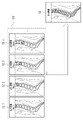
- FIG. 10 is a diagram showing how a marker position display map of markers corresponding to one vertebra of a plurality of vertebrae arranged in succession is generated;
- a tomographic image and a marker position display map of a marker corresponding to one vertebra are input to a semantic segmentation model for object identification, and an output image in which one vertebra is identified is output from the semantic segmentation model for object identification.
- FIG. 4 is a diagram showing;
- FIG. 10 is a diagram showing how an output image in which each vertebra is identified is generated from an output image in which one vertebra is identified;
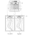
- FIG. 4 is a diagram showing how a marker position display map of markers corresponding to vertebrae arranged opposite to each other with one vertebra interposed therebetween among a plurality of vertebrae arranged continuously is generated.
- FIG. 10 is a diagram showing how a semantic segmentation model for identifying an object is output from an output image.
- FIG. 10 is a diagram showing how an output image in which each vertebra is identified is generated from an output image in which vertebrae arranged opposite to each other with one vertebra interposed therebetween are identified; It is a block diagram which shows the process part of CPU of 4th Embodiment. It is a figure which shows an extraction part. It is a figure which shows a probability distribution map.
- FIG. 10 is a diagram showing how a semantic segmentation model for identifying an object is output from an output image.
- FIG. 10 is a diagram showing how an output image in which each vertebra is identified is generated from an output image in which vertebrae arranged opposite to each other with one vertebra interposed therebetween are identified; It is a block diagram which shows the process part of CPU of 4th Embodiment. It is a figure which shows an extraction part. It is a figure which shows a probability distribution map.
- FIG. 10 illustrates a semantic segmentation model for point extraction
- FIG. 10 is a diagram showing an output part of a semantic segmentation model for point extraction
- FIG. 4 is a diagram showing an outline of processing in the learning phase of the semantic segmentation model for point extraction
- FIG. 11 illustrates non-maximum suppression processing
- the medical system 2 includes a CT (Computed Tomography) device 10 , a PACS (Picture Archiving and Communication System) server 11 , and a diagnosis support device 12 .
- CT apparatus 10 Computed Tomography
- PACS Physical Archiving and Communication System
- diagnosis support apparatus 12 are connected to a LAN (Local Area Network) 13 laid in the medical facility, and can communicate with each other via the LAN 13 .
- LAN Local Area Network
- the CT apparatus 10 radiographs the patient P at different projection angles to obtain a plurality of pieces of projection data, and reconstructs the obtained plurality of pieces of projection data to create a tomographic image 15 of the patient P. Output.
- the tomographic image 15 is voxel data representing the three-dimensional shape of the patient's P internal structure.
- the tomographic image 15 is an image of the patient P's upper body.
- FIG. 1 shows a tomographic image 15S of a sagittal section.
- a tomographic image 15 shows a spine SP composed of a plurality of vertebrae VB.
- CT apparatus 10 transmits tomographic image 15 to PACS server 11 .
- the PACS server 11 stores and manages the tomographic images 15 from the CT apparatus 10 .
- the tomographic image 15 is an example of an “analysis target image” and a “medical image” according to the technology of the present disclosure.
- Vertebra VB is also an example of the "object” and "structure” of this disclosure. Note that reconstruction of projection data may be performed by the diagnostic support device 12 or the like instead of the CT device 10 .
- the diagnosis support device 12 is, for example, a desktop personal computer, and is an example of an "image processing device" according to the technology of the present disclosure.
- the diagnosis support device 12 has a display 17 and an input device 18 .
- the input device 18 is a keyboard, mouse, touch panel, microphone, or the like.
- the doctor operates the input device 18 to transmit a distribution request for the tomographic image 15 of the patient P to the PACS server 11 .
- the PACS server 11 retrieves the tomographic image 15 of the patient P whose delivery has been requested and delivers it to the diagnosis support apparatus 12 .
- the diagnosis support device 12 displays the tomographic image 15 delivered from the PACS server 11 on the display 17 .
- the doctor observes the vertebrae VB of the patient P shown in the tomographic image 15 and diagnoses fractures, bone metastasis of cancer, and the like.
- CT device 10 and one diagnostic support device 12 are illustrated in FIG. 1, a plurality of CT devices 10 and multiple diagnostic support devices 12 may be provided.
- the computer constituting the diagnostic support device 12 includes a storage 20, a memory 21, a CPU (Central Processing Unit) 22, and a communication section 23 in addition to the display 17 and the input device 18 described above. I have. These are interconnected via bus lines 24 .
- the CPU 22 is an example of a “processor” according to the technology of the present disclosure.
- the storage 20 is a hard disk drive built into the computer constituting the diagnosis support device 12 or connected via a cable or network.
- the storage 20 is a disk array in which a plurality of hard disk drives are connected.
- the storage 20 stores a control program such as an operating system, various application programs, various data associated with these programs, and the like.
- a solid state drive may be used instead of the hard disk drive.
- the memory 21 is a work memory for the CPU 22 to execute processing.
- the CPU 22 loads the program stored in the storage 20 into the memory 21 and executes processing according to the program. Thereby, the CPU 22 comprehensively controls each part of the computer.
- the communication unit 23 controls transmission of various information with an external device such as the PACS server 11 . Note that the memory 21 may be built in the CPU 22 .
- the operating program 30 is stored in the storage 20 of the diagnostic support device 12 .
- the operating program 30 is an application program for causing a computer that configures the diagnosis support device 12 to function as an "image processing device” according to the technology of the present disclosure. That is, the operation program 30 is an example of the "image processing apparatus operation program” according to the technology of the present disclosure.
- the storage 20 also stores a tomographic image 15 and a semantic segmentation (hereinafter abbreviated as SS) model 33 for object identification.
- the object identification SS model 33 is an example of a “semantic segmentation model” according to the technology of the present disclosure.
- the storage 20 also stores the doctor's findings on the vertebrae VB shown in the tomographic image 15, various screen data to be displayed on the display 17, and the like.
- the CPU 22 of the computer that constitutes the diagnostic support device 12 cooperates with the memory 21 and the like to operate a read/write (hereinafter abbreviated as RW (Read Write)) control unit 40 and an instruction reception unit. 41 , a marker position display map generation unit 42 , an object identification unit 43 , an anatomical naming unit 44 , and a display control unit 45 .
- RW Read Write
- the RW control unit 40 controls storage of various data in the storage 20 and reading of various data in the storage 20 .
- the RW control unit 40 receives the tomographic image 15 from the PACS server 11 and stores the received tomographic image 15 in the storage 20 .
- the RW control unit 40 receives the tomographic image 15 from the PACS server 11 and stores the received tomographic image 15 in the storage 20 .
- a plurality of tomographic images 15 may be stored in the storage 20 .
- the RW control unit 40 reads the tomographic image 15 of the patient P designated by the doctor for diagnosis from the storage 20 and outputs the read tomographic image 15 to the object identification unit 43 and the display control unit 45 .
- the RW control unit 40 acquires the tomographic image 15 by reading the tomographic image 15 from the storage 20 .
- the RW control unit 40 also reads the object identification SS model 33 from the storage 20 and outputs the read object identification SS model 33 to the object identification unit 43 .
- the instruction reception unit 41 receives various instructions from the doctor through the input device 18.
- the instructions received by the instruction receiving unit 41 include, for example, an instruction to analyze the tomographic image 15, an instruction to input a marker MK (see FIG. 5) indicating the position of the vertebrae VB in the tomographic image 15, and a finding of the vertebrae VB in the storage 20.
- the instruction receiving unit 41 When the instruction receiving unit 41 receives an analysis instruction, it outputs that fact to the display control unit 45 . Further, when receiving an input instruction for the marker MK, the instruction receiving unit 41 generates marker position information 50 representing the position of the marker MK in the tomographic image 15, and sends the generated marker position information 50 to the marker position display map generating unit 42. output to Furthermore, when receiving a finding storage instruction, the instruction accepting unit 41 outputs that fact to the RW control unit 40 together with the finding.
- the marker position display map generation unit 42 generates a marker position display map 51 representing the positions of the markers MK in the tomographic image 15 based on the marker position information 50 from the instruction reception unit 41 .
- the marker position display map generator 42 outputs the marker position display map 51 to the object identification unit 43 .
- the object identification unit 43 identifies each vertebra VB based on the tomographic image 15 and the marker position display map 51 . More specifically, the object identification unit 43 inputs the tomographic image 15 and the marker position display map 51 to the object identification SS model 33, and outputs an output image 52 in which each vertebra VB is identified (see also FIG. 12). ) is output from the SS model 33 for object identification. The object identifying section 43 outputs the output image 52 to the anatomical naming section 44 .
- the anatomical name assigning unit 44 assigns an anatomical name to each vertebra VB identified in the output image 52 .
- the anatomical naming unit 44 outputs to the display control unit 45 an assignment result 53 that is the result of assigning an anatomical name to the vertebrae VB.
- the display control unit 45 controls the display of various screens on the display 17.
- the various screens include a first screen 60 (see FIG. 4) for instructing analysis of the tomographic image 15 by the marker position display map generation unit 42, the object identification unit 43, and the anatomical name assignment unit 44, a marker MK and a third screen 115 (see FIG. 15) for displaying the grant result 53, and the like.
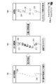
- FIG. 4 shows an example of the first screen 60 for instructing the analysis of the tomographic image 15.
- a tomographic image 15S of a sagittal section of a patient P whose spine SP is to be diagnosed is displayed on the first screen 60.
- a button group 61 for switching the display is provided below the tomographic image 15S.
- the tomographic image 15 of the axial section and the coronal section may be displayed.
- a finding input field 62 On the first screen 60, a finding input field 62, a message 63, an OK button 64, and an analysis button 65 are displayed.
- the doctor inputs the finding of the vertebra VB.
- the doctor moves the cursor 66 to the OK button 64 and selects it.
- the instruction receiving unit 41 receives the finding storage instruction.
- the RW control unit 40 associates the tomographic image 15 with the finding input in the finding input field 62 and stores them in the storage 20 .
- the message 63 prompts the user to select the analysis button 65. If the doctor wishes to analyze the tomographic image 15 prior to inputting his findings, he moves the cursor 66 to the analysis button 65 and selects it. Accordingly, the instruction receiving unit 41 receives the instruction to analyze the tomographic image 15 and outputs the instruction to the display control unit 45 .
- the display control unit 45 causes the screen to transition from the first screen 60 to the second screen 70 shown in FIG. 5 as an example.
- a message 71 and an input completion button 72 are displayed on the second screen 70 .
- the message 71 prompts selection of the input completion button 72 after the marker MK is attached to each vertebra VB.
- the marker MK is a point corresponding to one pixel 86 (see FIG. 8) of the tomographic image 15 in this example.
- the instruction accepting unit 41 accepts an input instruction for the marker MK.
- the marker position information 50 generated by the instruction receiving unit 41 is the XYZ coordinates of each marker MK.
- the X-axis is parallel to the horizontal direction
- the Y-axis is parallel to the front-rear direction
- the Z-axis is parallel to the vertical direction.
- each marker MK since the marker MK is attached to the tomographic image 15S of the sagittal section, each marker MK has the same value of the X coordinate among the XYZ coordinates of each marker MK.
- the Y-coordinate and Z-coordinate values are different for each marker MK.
- each marker MK is organized by assigning a number (No.) in ascending order of the Z coordinate.
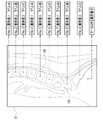
- the marker position display map 51 has elements 87 (see FIG. 8) corresponding to the pixels 86 of the tomographic image 15 on a one-to-one basis. This is data having an element value of 1 or 2, and an element value of 0 for an element 87 corresponding to a pixel 86 other than the marker MK. That is, the marker position display map 51 is data representing the position of the marker MK with an element value of 1 or 2.
- FIG. 6 the vertebrae VB and the like are indicated by dashed lines to aid understanding, but the actual marker position display map 51 does not show the vertebrae VB and the like.
- the marker position display map generation unit 42 assigns a label A to two adjacent vertebrae VB with an element value of 1 for one vertebrae VB, and a label B with an element value of 2 for the other vertebrae VB.
- the element value of vertebra VB of No. 1 is set to 1 and labeled A.
- the element value of the vertebra VB of 2 is set to 2 and labeled B.
- the element value of vertebra VB of No. 7 is set to 1 and labeled A.
- the element value of 8 vertebrae VB is set to 2 and labeled B.
- the marker position display map generator 42 assigns the labels A and B in this way, and as a result, No.
- the 1st, 3rd, 5th, 7th, and 9th vertebrae VB are examples of the "first object” according to the technology of the present disclosure.
- the 2nd, 4th, 6th, and 8th vertebrae VB are examples of a "second object” according to the techniques of this disclosure.
- Label A is an example of a "first label” according to the technology of the present disclosure
- label B is an example of a "second label” according to the technology of the present disclosure.
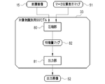
- the object identification SS model 33 has a compression unit 80 and an output unit 81, as shown in FIG.
- the tomographic image 15 and the marker position display map 51 are input to the compression unit 80 .
- the tomographic image 15 input to the compression unit 80 is, for example, the tomographic image 15S of the sagittal section from which the marker position display map 51 is generated.
- the compression unit 80 converts the tomographic image 15 and the marker position display map 51 into a feature quantity map 82 .
- the compression unit 80 passes the feature quantity map 82 to the output unit 81 .
- the output unit 81 outputs the output image 52 based on the feature quantity map 82 .
- the compression unit 80 combines the tomographic image 15 and the marker position display map 51 in the channel direction by performing a convolution operation as shown in FIG. 8 as an example.
- the compression unit 80 has a convolution layer 85 to which the tomographic image 15 and the marker position display map 51 are input.
- the convolution layer 85 applies, for example, a 3 ⁇ 3 filter F1 to the tomographic image 15 having a plurality of pixels 86 arranged two-dimensionally.
- the convolution layer 85 applies, for example, a 3 ⁇ 3 filter F2 to the marker position display map 51 having a plurality of elements 87 arranged two-dimensionally.
- the pixel value e1 of one target pixel 86I of the pixels 86 the pixel values a1, b1, c1, d1, f1, g1, h1, and i1 of eight pixels 86S adjacent to the target pixel 86I, and , which is one of the elements 87 and corresponds to the target pixel 86I, and the element values a2, b2, c2, d2, and f2 of the eight elements 87S adjacent to the target pixel 87I. , g2, h2, and i2.
- the convolution layer 85 sequentially performs a convolution operation while shifting the target pixel 86I and the target element 87I one by one, and outputs the element value of the element 89 of the operation data 88 .
- operation data 88 having a plurality of elements 89 arranged two-dimensionally is obtained.
- the tomographic image 15 and the marker position display map 51 are combined in the channel direction.
- the coefficients of filter F1 be r1, s1, t1, u1, v1, w1, x1, y1, and z1.
- the coefficients of filter F2 be r2, s2, t2, u2, v2, w2, x2, y2, and z2.
- the element value k of the element 89I of the operation data 88 which is the result of the convolution operation on the target pixel 86I and the target element 87I, is obtained by calculating the following equation (1), for example.
- the compression unit 80 further has a plurality of convolution layers 95 in addition to the convolution layers 85 .
- a convolution layer 95 applies, for example, a 3 ⁇ 3 filter F to target data 97 having a plurality of elements 96 arranged two-dimensionally. Then, the element value e of one target element 96I of the elements 96 and the element values a, b, c, d, f, g, h, and i of eight elements 96S adjacent to the target element 96I are convoluted. .
- the convolution layer 95 sequentially performs a convolution operation on each element 96 of the target data 97 while shifting the target element 96I by one element, and outputs the element value of the element 99 of the operation data 100 .
- operation data 100 having a plurality of elements 99 arranged two-dimensionally is obtained.
- the target data 97 input to the convolution layer 95 is, for example, the operation data 88 shown in FIG. 8, or reduction operation data 100S (see FIG. 11), which will be described later.
- One piece of calculation data 100 is output for one filter F.
- operation data 100 is output for each filter F.
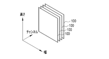
- FIG. 10 That is, as shown in FIG. 10 as an example, the calculation data 100 are generated for the number of filters F applied to the target data 97 .
- the calculation data 100 has a plurality of elements 99 arranged two-dimensionally, it has width and height.
- the number of calculation data 100 is called the number of channels.
- FIG. 10 illustrates four channels of operation data 100 output by applying four filters F to one target data 97 .
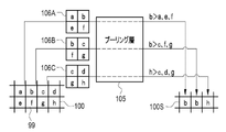
- the compression unit 80 has a pooling layer 105 in addition to the convolution layers 85 and 95 .
- the pooling layer 105 obtains the local statistic of the element value of the element 99 of the operation data 100, and generates reduced operation data 100S having the obtained statistic as the element value.
- the pooling layer 105 performs maximum value pooling processing for obtaining the maximum value of the element values within the block 106 of 2 ⁇ 2 elements as a local statistic. By performing the processing while shifting the block 106 by one element in the width direction and the height direction, the reduced calculation data 100S is reduced to half the size of the original calculation data 100 .
- the compression unit 80 repeats the convolution processing by the convolution layers 85 and 95 and the pooling processing by the pooling layer 105 multiple times, thereby outputting the final operation data 100 .
- This final calculation data 100 is the feature quantity map 82 .
- the compression unit 80 also performs skip layer processing and the like for transferring the calculation data 100 to the output unit 81 .
- the output unit 81 performs upsampling processing to enlarge the size of the feature quantity map 82 to obtain an enlarged feature quantity map.
- the output unit 81 also performs convolution processing at the same time as the upsampling processing.
- the output unit 81 also performs a merge process of combining the enlarged feature quantity map and the calculation data 100 passed from the compression unit 80 in skip layer processing.
- the output unit 81 further performs convolution processing after the merge processing. Through such various processes, the output unit 81 outputs the output image 52 from the feature quantity map 82 .
- the SS model 33 for object identification is constructed by CNN.
- Examples of CNN include U-Net and ResNet (Residual Network).
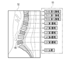
- the output image 52 is an image in which each vertebra VB is labeled with a class. More specifically, the output image 52 is No. Vertebrae VB of 1, 3, 5, 7, and 9 are identified as Class A corresponding to label A; 2, 4, 6, and 8 vertebrae VB are images identified as class B corresponding to label B; Class A is an example of the "first class” according to the technology of the present disclosure, and class B is an example of the "second class” according to the technology of the present disclosure.
- the SS model 33 for object identification is learned by being given learning data (also called teacher data) 110 in the learning phase.
- the learning data 110 includes a learning tomographic image 15L, a learning marker position display map 51L corresponding to the learning tomographic image 15L, and an annotation image 111 corresponding to the learning tomographic image 15L and the learning marker position display map 51L. It is a group.
- markers MK are attached to the vertebrae VB appearing in the learning tomographic image 15L, and labels A and B are alternately attached.
- the annotation image 111 is an image obtained by labeling each vertebra VB appearing in the learning tomographic image 15L with a class corresponding to the label given in the learning marker position display map 51L.
- the learning tomographic image 15L and the learning marker position display map 51L are input to the object identification SS model 33.
- the object identification SS model 33 outputs a learning output image 52L for the learning tomographic image 15L and the learning marker position display map 51L.
- the loss calculation of the object identification SS model 33 is performed.
- Various coefficients (such as the coefficients of the filter F) of the object identification SS model 33 are updated according to the result of the loss calculation, and the object identification SS model 33 is updated according to the update settings.
- the learning tomographic image 15L and the learning marker position display map 51L are input to the object identification SS model 33, and the learning output from the object identification SS model 33.
- the series of processes of outputting the image 52L, calculating the loss, setting the update, and updating the SS model 33 for object identification are repeated while the learning data 110 are exchanged.
- Repetition of the above series of processes ends when the prediction accuracy of the learning output image 52L with respect to the annotation image 111 reaches a predetermined set level.
- the object identification SS model 33 whose prediction accuracy reaches the set level in this manner is stored in the storage 20 and used in the object identification unit 43 . Regardless of the prediction accuracy of the learning output image 52L with respect to the annotation image 111, learning may be terminated when the series of processes described above is repeated a set number of times.
- the assigned result 53 is the anatomical name of each vertebra VB such as Th10 (10th thoracic vertebra), L1 (1st lumbar vertebrae), and S1 (sacrum).
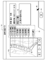
- FIG. 15 shows an example of the third screen 115 displaying the grant result 53.
- the display control unit 45 causes the screen to transition from the second screen 70 shown in FIG. 5 to the third screen 115 .
- the application result 53 is displayed next to the tomographic image 15S.
- a finding input field 62 and an OK button 64 are displayed, like the first screen 60 of FIG.
- the doctor moves the cursor 66 to the OK button 64 and selects it.
- the instruction receiving unit 41 receives the finding storage instruction, as in the case of FIG.
- the RW control unit 40 associates the tomographic image 15 with the finding input in the finding input field 62 and stores them in the storage 20 .
- the operation program 30 when the operation program 30 is activated in the diagnosis support device 12, as shown in FIG. It functions as an object identifying section 43 , an anatomical naming section 44 and a display control section 45 .
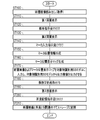
- the RW control unit 40 reads from the storage 20 the tomographic image 15 of the patient P whose spine SP is to be diagnosed (step ST100). A tomographic image 15 is thus obtained. The tomographic image 15 is output from the RW controller 40 to the display controller 45 . Then, under the control of the display control section 45, the first screen 60 shown in FIG. 4 is displayed on the display 17 (step ST110).
- the instruction receiving unit 41 receives an instruction to analyze the tomographic image 15 (step ST120). Under the control of the display control section 45, the first screen 60 is changed to the second screen 70 shown in FIG. 5 (step ST130).
- the doctor selects the input completion button 72 after the marker MK is attached to each vertebra VB.
- the input instruction for the marker MK is accepted by the instruction accepting unit 41 (step ST140).
- the instruction receiving unit 41 generates the marker position information 50 representing the position of the marker MK (step ST150).
- the marker position information 50 is output from the instruction receiving portion 41 to the marker position display map generating portion 42 .
- the marker position display map generator 42 generates the marker position display map 51 shown in FIG. 6 based on the marker position information 50 (step ST160).
- the marker position display map 51 is output from the marker position display map generation section 42 to the object identification section 43 .
- the tomographic image 15 and the SS model 33 for object identification are input from the RW control unit 40 to the object identification unit 43 .
- the object identification unit 43 the tomographic image 15 and the marker position display map 51 are input to the object identification SS model 33 as shown in FIG. 7 .
- the tomographic image 15 and the marker position display map 51 are combined in the channel direction.
- the output image 52 is output from the object identification SS model 33 (step ST170).
- the output image 52 is output from the object identifying section 43 to the anatomical naming section 44 .
- the anatomical name assignment unit 44 assigns an anatomical name to each vertebra VB identified in the output image 52 (step ST180).
- the assignment result 53 is output from the anatomical name assignment unit 44 to the display control unit 45 .
- the third screen 115 shown in FIG. 15 is displayed on the display 17 (step ST190).
- the doctor moves the cursor 66 to the OK button 64 and selects it.
- the finding storage instruction is accepted by the instruction accepting section 41 (step ST200).
- the tomographic image 15 and the finding entered in the finding input field 62 are associated and stored in the storage 20 (step ST210).
- the CPU 22 of the diagnosis support device 12 includes the RW control unit 40, the instruction reception unit 41, the marker position display map generation unit 42, and the object identification unit 43.
- the RW control unit 40 acquires the tomographic images 15 showing the vertebrae VB, which are a plurality of consecutively arranged objects of the same type, by reading from the storage 20 .
- the instruction receiving unit 41 receives input of a marker MK indicating the position of the vertebra VB in the tomographic image 15 .
- the marker position display map generation unit 42 generates a marker position display map 51 representing the positions of the markers MK within the tomographic image 15 .
- the object identification unit 43 inputs the tomographic image 15 and the marker position display map 51 to the object identification SS model 33, and causes the object identification SS model 33 to output an output image 52 in which each vertebra VB is identified. Therefore, compared to the case where the vertebrae VB are identified without any clues, it is possible to improve the identification accuracy of the vertebrae VB by the amount of the clues of the markers MK.
- the marker position display map generation unit 42 generates a marker position display map 51 of the markers MK corresponding to all of the vertebrae VB arranged in succession. At this time, the marker position display map generation unit 42 assigns a label A to one vertebra VB and a Label B.
- the object identification unit 43 outputs an output image 52 in which one vertebrae VB is identified as class A corresponding to label A and the other vertebrae VB is identified as class B corresponding to label B, to the object identification SS model 33. output from Therefore, all vertebrae VB can be identified at once, and processing time can be shortened.
- the object identification unit 43 combines the tomographic image 15 and the marker position display map 51 in the channel direction in the object identification SS model 33 . Processing time can be shortened compared to the case where the tomographic image 15 and the marker position display map 51 are input to separate compression units.
- the object identification SS model 33 receives the learning tomographic image 15L and the learning marker position display map 51L as inputs, and generates a learning output image according to the learning tomographic image 15L and the learning marker position display map 51L. 52L is output.
- the object identification SS model 33 is an annotation image 111 generated based on the learning output image 52L and the learning tomographic image 15L, and is an annotation image in which the vertebrae VB with the marker MK is annotated. It is learned based on comparison with 111. Therefore, it is possible to obtain the object identification SS model 33 that outputs a corresponding output image 52 in response to the input of the tomographic image 15 and the marker position display map 51 .
- the vertebra VB which constitutes the spine SP
- various identification methods have been proposed in the past, making it an urgent issue to improve identification accuracy. Therefore, in this example, in which the tomographic image 15 of the spine SP of the patient P is used as a medical image, and the vertebrae VB constituting the spine SP is used as a structure, the configuration matches the urgent problem of increasing the accuracy of identifying the vertebrae VB. You can say that.
- the tomographic image 15 input to the compression unit 80 is not limited to the tomographic image 15S of the sagittal section from which the marker position display map 51 was generated.
- several tomographic images of the sagittal section before and after the tomographic image 15S of the sagittal section from which the marker position display map 51 is generated. 15S may be input to the compression unit 80 .
- the identification result of the vertebrae VB for one sagittal cross-sectional tomographic image 15S may be applied to several front and rear tomographic images 15S of the sagittal cross-section.
- the marker MK is not limited to a point corresponding to one pixel 86 of the tomographic image 15 .
- a circular area composed of several to several tens of pixels 86 centered on the point clicked by the cursor 66 may be used.
- the marker MK may be an amorphous region composed of a plurality of pixels 86 that is roughly painted by the doctor within the vertebrae VB.
- the marker position display map 51 sets the element values of the elements 87 corresponding to the plurality of pixels 86 in the region filled out by the doctor to, for example, 1 or 2, and the element values 87 corresponding to the pixels 86 other than the region filled out by the doctor. becomes data whose element value is 0.
- the position where the marker MK is attached is not limited to the point that seems to be the center of the vertebral body of vertebra VB. It may be a point that seems to be the tip of the spinous process of the vertebral arch. Alternatively, it may be a point that seems to be the center of the vertebral foramen, which is the hole through which the spinal cord passes.
- the element value of label A is 1 and the element value of label B is 2, but it is not limited to this. It is sufficient if the element values of label A and label B are different from each other.
- the element value of label A may be 1 and the element value of label B may be -1.
- the types of labels are not limited to the two types of labels A and B. Three or more labels may be attached.
- the element values of No. 1, 4, and 7 vertebrae VB are assigned a label A
- the element values of No. 2, 5, and 8 vertebrae VB are assigned a label B of 2
- the No. 3, 6, and 9 vertebrae VB may be labeled C with a component value of 3.
- the output image 52 is No. 1, 4, and 7 vertebrae VB are identified as class A corresponding to label A
- 2, 5, and 8 vertebrae VB are identified as class B corresponding to label B
- Vertebrae VB of 3, 6, and 9 are images identified as class C corresponding to label C.
- each vertebra VB is identified, but this is not the only option.
- the vertebrae VB may be identified as preprocessing for CAD (Computer-Aided Diagnosis) for extracting lesion candidates such as bone fractures and bone metastasis of cancer.
- CAD Computer-Aided Diagnosis
- the marker position display map 51 of the markers MK corresponding to all of the plurality of vertebrae VB arranged in succession is generated, but the present invention is not limited to this.
- the second embodiment shown in FIGS. 19 to 21 may also be used.
- the marker position display map generator 42 generates a marker position display map group 130 based on the marker position information 50.
- FIG. The marker position display map group 130 includes No. 1, a marker position display map 51_1 representing the position of the marker MK attached to the vertebra VB of No. 1; 2, a marker position display map 51_2 representing the position of the marker MK attached to the vertebra VB of No. 2; A marker position display map 51_3, No. 3, representing the position of the marker MK attached to the vertebra VB of No. 3. . . showing the positions of the markers MK attached to the 4 vertebrae VB. That is, in the present embodiment, the marker position display map generation unit 42 generates the marker position display map 51 of the marker MK corresponding to one vertebra VB among the plurality of vertebrae VB arranged continuously.
- the tomographic image 15 and one of the marker position display maps 51 constituting the marker position display map group 130 are input to the object identification SS model 133 of the present embodiment. be done.
- the object identifying SS model 133 outputs an output image 52 in which one vertebra VB attached with a marker MK whose position is indicated in the marker position display map 51 is identified.
- No. A marker position display map 51_1 representing the position of the marker MK attached to the vertebra VB of No. 1 is input to the object identifying SS model 133 together with the tomographic image 15. 1 illustrates how an output image 52_1 in which one vertebra VB is identified is output from the SS model 133 for object identification.
- the learning tomographic image 15L and the learning marker position display map 51L of the marker MK corresponding to one vertebra VB are input to the object identification SS model 133. Loss calculation is then performed based on the learning output image 52L output from the object identification SS model 133 and the annotation image in which one vertebra VB with the marker MK is annotated.
- an output image group 135 shown in FIG. 21 is obtained as an example.
- the output image group 135 includes No. 1 vertebrae VB identified, output image 52_1, no. 2 vertebrae VB identified, output image 52_2, no.
- the output image 52_3, No. 3, with the vertebra VB of No. 3 identified. contains an output image 52_4, .
- the object identification unit 43 generates an output image 52, in which each vertebrae VB is identified, to be finally output from the plurality of output images 52_1, 52_2, . . .
- the marker position display map generation unit 42 generates the marker position display map 51 of the marker MK corresponding to one vertebra VB out of the plurality of vertebrae VB arranged continuously.
- the object identification unit 43 causes the SS model for object identification 133 to output an output image 52 in which one vertebra VB is identified. Therefore, although the processing time is longer than that of the first embodiment, each vertebra VB can be identified with higher accuracy.
- all the vertebrae VB shown in the tomographic image 15 may be marked with the markers MK at once, or one vertebrae VB may be marked with the marker MK. Identifying may be repeated.
- the marker position display map generator 42 generates a marker position display map group 140 based on the marker position information 50.
- FIG. The marker position display map group 140 includes No. Marker position display maps 51_1, 3, 5, 7, and 9 representing the positions of markers MK attached to vertebrae VB of 1, 3, 5, 7, and 9; and marker position display maps 51_2, 4, 6, and 8 representing the positions of the markers MK attached to the 2nd, 4th, 6th, and 8th vertebrae VB. That is, in the present embodiment, the marker position display map generation unit 42 calculates the marker positions of the markers MK corresponding to the vertebrae VB arranged opposite to each other across one vertebrae VB among the plurality of vertebrae VB arranged in succession. A display map 51 is generated.
- the tomographic image 15 and one of the two marker position display maps 51 constituting the marker position display map group 140 are input to the object identification SS model 143 of the present embodiment. be done. Further, the object identification SS model 143 produces an output image 52 in which the vertebrae VB arranged opposite to each other across one vertebrae VB are identified to which the markers MK whose positions are indicated in the marker position display map 51 are attached. Output.
- No. Marker position display maps 51_1, 3, 5, 7, and 9 representing the positions of the markers MK attached to the vertebrae VB of 1, 3, 5, 7, and 9 are input to the SS model 143 for object identification together with the tomographic image 15. and No. Output images 52_1, 3, 5, 7, and 9 in which vertebrae VB of 1, 3, 5, 7, and 9 are identified are output from the SS model 143 for object identification.
- the learning tomographic image 15L and the learning marker position display map 51L of the markers MK corresponding to the vertebrae VB arranged opposite to each other across one vertebrae VB are input to the object identification SS model 143. be.
- the learning output image 52L output from the object identification SS model 143 and the vertebrae VB to which the marker MK is attached are annotated.
- a loss operation is performed based on the annotation image.
- the object identification SS model 143 includes the learning tomographic image 15L and the learning marker position of the marker MK corresponding to one vertebra VB, as in the object identification SS model 133 of the second embodiment.
- a display map 51L is input. Loss calculation is then performed based on the learning output image 52L output from the object identification SS model 143 and the annotation image in which one vertebra VB with the marker MK is annotated.
- the output image group 145 includes No. Output images 52_1, 3, 5, 7, 9 in which vertebrae VB of 1, 3, 5, 7, and 9 have been identified, and no. 2, 4, 6, and 8 vertebrae VB identified output images 52_2, 4, 6, 8; From these two output images 52_1, 3, 5, 7, 9 and 52_2, 4, 6, 8, the object identification unit 43 generates the final output image 52 in which each vertebra VB is identified. .
- the marker position display map generation unit 42 creates markers MK corresponding to the vertebrae VB arranged opposite to each other across one vertebrae VB among the plurality of vertebrae VB arranged continuously.
- a marker position display map 51 is generated.
- the object identification unit 43 causes the SS model for object identification 143 to output an output image 52 in which the vertebrae VB arranged opposite to each other across one vertebrae VB are identified. Therefore, each vertebra VB can be identified with high accuracy in a shorter processing time than in the second embodiment.
- all the vertebrae VB appearing in the tomographic image 15 may be marked with markers MK at once. attaching markers MK to the vertebrae VB of 1, 3, 5, 7 and 9 to identify these vertebrae VB;
- the 2nd, 4th, 6th, and 8th vertebrae VB may be marked with markers MK to identify these vertebrae VB separately.
- No. 1, 3, 5, 7, and 9 and no Although alternate cases such as 2, 4, 6, and 8 have been exemplified, the present invention is not limited to this. No. 1, 4, and 7, no. 2, 5 and 8 and no. It can be every two, such as 3, 6, and 9. Also, every three or four may be used. However, as a matter of course, the processing time is longer than in the case of every other one.
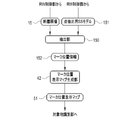
- an extraction unit 150 is constructed in the CPU of the diagnosis support device of this embodiment.
- the tomographic image 15 and the point extraction SS model 151 are input from the RW control unit 40 to the extraction unit 150 .
- the point extraction SS model 151 is stored in the storage 20 .
- the extraction unit 150 uses the point extraction SS model 151 to extract a point in each vertebra VB appearing on the tomographic image 15 as a marker MK.
- the center point CP (see FIG. 30) of the vertebral body is extracted as a point within the vertebra VB.
- the extraction unit 150 generates marker position information 152 representing the position of the center point CP of the vertebral body as the marker MK.
- the extractor 150 outputs the marker position information 152 to the marker position display map generator 42 .
- the marker position display map generation section 42 generates a marker position display map 51 based on the marker position information 152 and outputs the marker position display map 51 to the object identification section 43 . Since subsequent processing is the same as that of each of the above embodiments, description thereof is omitted.
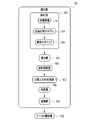
- the extraction unit 150 has an analysis unit 160, a selection unit 161, a non-maximum suppression processing unit 162, and a conversion unit 163.
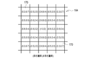
- the analysis unit 160 inputs the tomographic image 15 to the SS model for point extraction 151 and causes the SS model for point extraction 151 to output a probability distribution map 164 indicating the existence probability of the central point CP of the vertebral body.
- the analysis unit 160 outputs the probability distribution map 164 to the selection unit 161 .
- the probability distribution map 164 has elements 170 corresponding to the pixels 86 of the tomographic image 15 on a one-to-one basis. and non-existence probability are registered data.
- element values (1.0, 0) represent that the existence probability of the central point CP of the vertebral body is 100% and the non-existence probability is 0%.
- the selection unit 161 selects the elements 170 having the presence probability of the center point CP of the vertebral body equal to or greater than a threshold value (for example, 0.9) in the probability distribution map 164 as candidates 200 ( (see FIG. 31).
- the selection unit 161 generates a point candidate image 165 (see also FIG. 31) representing the selected candidate 200 and outputs the generated point candidate image 165 to the non-maximum suppression processing unit 162 .
- the point candidate image 165 is, for example, an image in which the pixel value of the pixel corresponding to the candidate 200 is 1 and the pixel value of the other pixels is 0.
- the non-maximum suppression processing unit 162 performs non-maximum suppression processing on each candidate 200 of the point candidate image 165, and as a result, generates a point image 166 (see also FIG. 31) representing the center point CP of the vertebral body.
- the point image 166 is, for example, an image in which the pixel value of the pixel corresponding to the center point CP of the vertebral body is 1, and the pixel value of the other pixels is 0. In other words, the point image 166 is nothing but an image representing the marker MK indicating the position of the vertebra VB in the tomographic image 15 .
- the non-maximum suppression processing unit 162 outputs the point image 166 to the conversion unit 163 .
- the conversion unit 163 accepts the input of the marker MK.
- the conversion unit 163 converts the point image 166 into marker position information 152 .
- the SS model 151 for point extraction has a compression unit 180 and an output unit 181, like the SS model 33 for object identification.
- a tomographic image 15 is input to the compression unit 180 .
- the compression unit 180 performs convolution processing, pooling processing, and the like on the tomographic image 15 to convert the tomographic image 15 into a feature amount map 182 .
- the compression unit 180 passes the feature quantity map 182 to the output unit 181 .
- the output unit 181 outputs the probability distribution map 164 based on the feature quantity map 182 .
- the output unit 181 has a decoder unit 190 and a probability distribution map generation unit 191.
- the decoder unit 190 performs upsampling processing, convolution processing, merging processing, etc. on the feature amount map 182 in the same manner as the output unit 81 of the object identification SS model 33 to generate a final feature amount map 192 .
- the final feature quantity map 192 is also called logits, and has elements in one-to-one correspondence with the pixels 86 of the tomographic image 15 .
- Each element of the final feature map 192 has an element value associated with the center point CP of the vertebral body being extracted. For example, the element value of the element where the center point CP of the vertebral body seems to be is higher than the element values of the other elements.
- the decoder section 190 outputs the final feature quantity map 192 to the probability distribution map generation section 191 .
- the probability distribution map generation unit 191 generates the probability distribution map 164 from the final feature quantity map 192 using a well-known activation function.
- the probability distribution map generator 191 applies, for example, a softmax function to calculate e 2 /(e 2 +e 1.5 ) and e 1.5 /(e 2 +e 1.5 ). Then, the probability that the central point CP of the vertebral body exists in the element, that is, the existence probability of 0.62 ( ⁇ e 2 /(e 2 +e 1.5 )) is derived, and the central point CP of the vertebral body is derived in the element. 0.38 ( ⁇ e 1.5 /(e 2 +e 1.5 )) is derived as the probability that does not exist (hereinafter referred to as non-existence probability).
- a sigmoid function may be used instead of the softmax function.
- the point extraction SS model 151 is learned by being given learning data 195 in the learning phase.
- the learning data 195 is a set of a learning tomographic image 15L and an annotation image 196 corresponding to the learning tomographic image 15L.
- the annotation image 196 is an image in which the center point CP of the vertebral body of each vertebra VB appearing in the learning tomographic image 15L is annotated.
- the annotation image 196 is an image in which the pixel value of the pixel 197A corresponding to the center point CP of the vertebral body is 1, and the pixel value of the other pixels 197B is 0.
- the learning tomographic image 15L is input to the point extraction SS model 151.
- the point extraction SS model 151 outputs a learning probability distribution map 164L for the learning tomographic image 15L. Based on this learning probability distribution map 164L and the annotation image 196, the loss calculation of the point extraction SS model 151 is performed. Various coefficients of the point extraction SS model 151 are updated according to the result of the loss calculation, and the point extraction SS model 151 is updated according to the update settings.
- a weighted cross entropy function is used in the loss calculation of the SS model 151 for point extraction.
- the cross entropy function compares when the existence probability of the center point CP of the vertebral body among the element values of the element 170 of the learning probability distribution map 164L and the pixel value of the annotation image 196 are relatively close values. take a relatively low value. In other words, in this case, the loss is estimated to be small.
- the cross entropy function is a value in which the existence probability of the center point CP of the vertebral body among the element values of the element 170 of the learning probability distribution map 164L and the pixel value of the annotation image 196 are relatively deviated. takes a relatively high value. In other words, in this case, the loss is estimated to be large.
- the weight of the cross entropy function is set to 10, for example, for the pixel 197A corresponding to the central point CP of the vertebral body annotated in the annotation image 196, and 1, for example, to the other pixels 197B. Since the central point CP of the vertebral body is very small, it will be buried if no measures are taken, making it difficult to learn. However, since the pixel 197A corresponding to the center point CP of the vertebral body is assigned a greater weight than the other pixels 197B, learning can be performed intensively on the center point CP of the vertebral body.
- the input of the learning tomographic image 15L to the point extraction SS model 151, the output of the learning probability distribution map 164L from the point extraction SS model 151, the loss calculation, and the update setting. , and updating of the point extraction SS model 151 are repeated while the learning data 195 are exchanged.
- Repetition of the above series of processes ends when the prediction accuracy of the learning probability distribution map 164L for the annotation image 196 reaches a predetermined set level.
- the point extraction SS model 151 whose prediction accuracy reaches the set level in this manner is stored in the storage 20 and used in the extraction unit 150 . Regardless of the prediction accuracy of the learning probability distribution map 164L for the annotation image 196, learning may be terminated when the series of processes described above is repeated a set number of times.
- FIG. 31 shows an example of non-maximum suppression processing by the non-maximum suppression processing unit 162.
- FIG. A point candidate image 165 is obtained by simply selecting, as candidates 200, elements 170 whose existence probability in the probability distribution map 164 is equal to or greater than the threshold. Therefore, not all candidates 200 are truly vertebral body center points CP. Therefore, by performing non-maximum suppression processing, the true center point CP of the vertebral body is narrowed down from among the plurality of candidates 200 .
- the non-maximum suppression processing unit 162 first assigns a rectangular frame 201 to each candidate 200 of the point candidate image 165 .
- the rectangular frame 201 has a preset size corresponding to the vertebrae VB, for example, a size one size larger than one vertebrae VB.
- the center of rectangular frame 201 coincides with candidate 200 .
- the non-maximum suppression processing unit 162 calculates the IoU (Intersection over Union) of the rectangular frame 201 assigned to each candidate 200 .
- the IoU is a value obtained by dividing the overlapping area (Area of Overlap) of the two rectangular frames 201 by the area (Area of Union) where the two rectangular frames 201 are integrated.
- the non-maximum suppression processing unit 162 leaves one representative rectangular frame 201 and deletes the other one rectangular frame 201 for each candidate 200 for two rectangular frames 201 whose IoU is equal to or greater than a threshold value (for example, 0.3).
- a threshold value for example, 0.3
- points within the vertebrae VB are automatically extracted, and the extracted points are accepted as markers MK. Therefore, the doctor can save the trouble of inputting the marker MK. It is not necessary to display the second screen 70 shown in FIG. The doctor only has to select the analysis button 65 on the first screen 60 .
- the annotation image 196 is not limited to an image annotated with one pixel 197A indicating the center point CP of the vertebral body.
- An image in which a circular region composed of several to several tens of pixels around the central point CP of the vertebral body is annotated may be used.
- the point to be extracted is not limited to the central point CP of the vertebral body. It may be the tip of the spinous process of the vertebral arch or the center of the vertebral foramen.
- the RW control unit 40 the instruction reception unit 41, the marker position display map generation unit 42, the target object identification unit 43, the anatomical name assignment unit 44, the display control unit 45, the extraction unit 150, the analysis
- the processing unit processing unit
- the following various processors are used.
- Various processors include, as described above, in addition to the CPU 22 which is a general-purpose processor that executes software (operation program 30) and functions as various processing units, FPGAs (Field Programmable Gate Arrays), etc.
- Programmable Logic Device which is a processor whose circuit configuration can be changed, ASIC (Application Specific Integrated Circuit), etc. It includes electrical circuits and the like.
- One processing unit may be configured with one of these various processors, or a combination of two or more processors of the same or different type (for example, a combination of a plurality of FPGAs and/or a CPU and combination with FPGA). Also, a plurality of processing units may be configured by one processor.
- a single processor is configured by combining one or more CPUs and software.
- a processor functions as multiple processing units.
- SoC System On Chip
- a processor that realizes the functions of the entire system including multiple processing units with a single IC (Integrated Circuit) chip. be.
- the various processing units are configured using one or more of the above various processors as a hardware structure.
- an electric circuit combining circuit elements such as semiconductor elements can be used.
- the image to be analyzed is not limited to the tomographic image 15 obtained from the CT device 10.
- it may be a tomographic image obtained from an MRI (Magnetic Resonance Imaging) device.
- the image to be analyzed is not limited to a three-dimensional image such as a tomographic image.
- it may be a two-dimensional image such as a simple radiographic image.
- the structure is not limited to vertebrae VB.
- a finger bone or the like may be used.
- images to be analyzed are not limited to medical images.
- the object is not limited to the structure of the body.
- an image of the street may be used as the image to be analyzed, and the target object may be the face of a person.
- the technology of the present disclosure can also appropriately combine various embodiments and/or various modifications described above. Moreover, it is needless to say that various configurations can be employed without departing from the scope of the present invention without being limited to the above embodiments. Furthermore, the technology of the present disclosure extends to storage media that non-temporarily store programs in addition to programs.
- a and/or B is synonymous with “at least one of A and B.” That is, “A and/or B” means that only A, only B, or a combination of A and B may be used.
- a and/or B means that only A, only B, or a combination of A and B may be used.
Landscapes
- Engineering & Computer Science (AREA)
- Health & Medical Sciences (AREA)
- Medical Informatics (AREA)
- Public Health (AREA)
- General Health & Medical Sciences (AREA)
- Biomedical Technology (AREA)
- Physics & Mathematics (AREA)
- Life Sciences & Earth Sciences (AREA)
- Theoretical Computer Science (AREA)
- Nuclear Medicine, Radiotherapy & Molecular Imaging (AREA)
- Radiology & Medical Imaging (AREA)
- Epidemiology (AREA)
- Primary Health Care (AREA)
- General Physics & Mathematics (AREA)
- Pathology (AREA)
- Optics & Photonics (AREA)
- Computer Vision & Pattern Recognition (AREA)
- High Energy & Nuclear Physics (AREA)
- Multimedia (AREA)
- Heart & Thoracic Surgery (AREA)
- Molecular Biology (AREA)
- Surgery (AREA)
- Animal Behavior & Ethology (AREA)
- Veterinary Medicine (AREA)
- Biophysics (AREA)
- Databases & Information Systems (AREA)
- Data Mining & Analysis (AREA)
- Business, Economics & Management (AREA)
- Orthopedic Medicine & Surgery (AREA)
- Dentistry (AREA)
- Oral & Maxillofacial Surgery (AREA)
- General Business, Economics & Management (AREA)
- Software Systems (AREA)
- Pulmonology (AREA)
- Quality & Reliability (AREA)
- Apparatus For Radiation Diagnosis (AREA)
- Image Analysis (AREA)
Abstract
プロセッサと、プロセッサに接続または内蔵されたメモリと、を備え、プロセッサは、連続して並んだ複数の同種の対象物が写る解析対象画像を取得し、解析対象画像内の対象物の位置を示すマーカの入力を受け付け、解析対象画像内のマーカの位置を表すマーカ位置表示マップを生成し、解析対象画像およびマーカ位置表示マップをセマンティックセグメンテーションモデルに入力し、対象物が識別された出力画像をセマンティックセグメンテーションモデルから出力させる、画像処理装置。
Description
本開示の技術は、画像処理装置、画像処理装置の作動方法、画像処理装置の作動プログラムに関する。
従来、解析対象画像に写る対象物を識別する画像処理が様々な分野で行われている。最近では、解析対象画像に写る対象物を画素単位で識別するセマンティックセグメンテーションを行う畳み込みニューラルネットワーク(以下、CNN(convolutional Neural Network)と略す)を用いる手法が注目されている。例えば特開2020-025730号公報には、患者に放射線を照射して得られた放射線画像を解析対象画像とし、CNNを用いて放射線画像に写る複数の対象物を識別することが記載されている。対象物には、肺野、脊椎(背骨)、およびその他の領域が例示され、脊椎のうちの胸椎と腰椎を別に識別することも記載されている。
特開2020-025730号公報には、前述のように、CNNを用いて脊椎を識別することが記載されている。しかしながら、実際、CNNは、例えば脊椎を構成する複数の椎骨の1つ1つ等、連続して並んだ複数の同種の対象物の識別精度があまりよくない。このため、隣接する複数の椎骨を1つの椎骨として誤って識別する等、しばしば識別が上手くいかないことがあった。
本開示の技術に係る1つの実施形態は、連続して並んだ複数の同種の対象物の識別精度を高めることが可能な画像処理装置、画像処理装置の作動方法、画像処理装置の作動プログラムを提供する。
本開示の画像処理装置は、プロセッサと、プロセッサに接続または内蔵されたメモリと、を備え、プロセッサは、連続して並んだ複数の同種の対象物が写る解析対象画像を取得し、解析対象画像内の対象物の位置を示すマーカの入力を受け付け、解析対象画像内のマーカの位置を表すマーカ位置表示マップを生成し、解析対象画像およびマーカ位置表示マップをセマンティックセグメンテーションモデルに入力し、対象物が識別された出力画像をセマンティックセグメンテーションモデルから出力させる。
プロセッサは、連続して並んだ複数の同種の対象物のうちの1つの対象物に対応するマーカのマーカ位置表示マップを生成し、1つの対象物が識別された出力画像をセマンティックセグメンテーションモデルから出力させることが好ましい。
プロセッサは、連続して並んだ複数の同種の対象物のうち、少なくとも1つの対象物を挟んで対向配置された対象物に対応するマーカのマーカ位置表示マップを生成し、少なくとも1つの対象物を挟んで対向配置された対象物が識別された出力画像をセマンティックセグメンテーションモデルから出力させることが好ましい。
プロセッサは、連続して並んだ複数の同種の対象物の全てに対応するマーカのマーカ位置表示マップを生成し、マーカ位置表示マップを生成する際に、連続して並んだ複数の同種の対象物のうちの隣接する第1対象物および第2対象物について、第1対象物に対して第1ラベルを付し、第2対象物に対して第1ラベルとは異なる第2ラベルを付し、第1対象物が第1ラベルに対応する第1クラスとして識別され、第2対象物が第2ラベルに対応する第2クラスとして識別された出力画像をセマンティックセグメンテーションモデルから出力させることが好ましい。
プロセッサは、セマンティックセグメンテーションモデルにおいて、解析対象画像およびマーカ位置表示マップをチャンネル方向に結合することが好ましい。
セマンティックセグメンテーションモデルは、学習フェーズにおいて、学習用解析対象画像および学習用マーカ位置表示マップが入力され、学習用解析対象画像および学習用マーカ位置表示マップに応じて学習用出力画像を出力し、学習用出力画像と、学習用解析対象画像を元に生成されたアノテーション画像であって、マーカが付された対象物がアノテーションされたアノテーション画像との比較に基づいて学習されることが好ましい。
解析対象画像は患者の身体内を写した医用画像であり、対象物は身体の構造物であることが好ましい。
医用画像は患者の脊椎を写した画像であり、構造物は脊椎を構成する椎骨であることが好ましい。
本開示の画像処理装置の作動方法は、連続して並んだ複数の同種の対象物が写る解析対象画像を取得すること、解析対象画像内の対象物の位置を示すマーカの入力を受け付けること、解析対象画像内のマーカの位置を表すマーカ位置表示マップを生成すること、並びに、解析対象画像およびマーカ位置表示マップをセマンティックセグメンテーションモデルに入力し、対象物が識別された出力画像をセマンティックセグメンテーションモデルから出力させること、を含む。
本開示の画像処理装置の作動プログラムは、連続して並んだ複数の同種の対象物が写る解析対象画像を取得すること、解析対象画像内の対象物の位置を示すマーカの入力を受け付けること、解析対象画像内のマーカの位置を表すマーカ位置表示マップを生成すること、並びに、解析対象画像およびマーカ位置表示マップをセマンティックセグメンテーションモデルに入力し、対象物が識別された出力画像をセマンティックセグメンテーションモデルから出力させること、を含む処理をコンピュータに実行させる。
本開示の技術によれば、連続して並んだ複数の同種の対象物の識別精度を高めることが可能な画像処理装置、画像処理装置の作動方法、画像処理装置の作動プログラムを提供することができる。
[第1実施形態]
一例として図1に示すように、医療システム2は、CT(Computed Tomography)装置10、PACS(Picture Archiving and Communication System)サーバ11、および診断支援装置12を備える。これらCT装置10、PACSサーバ11、および診断支援装置12は、医療施設内に敷設されたLAN(Local Area Network)13に接続されており、LAN13を介して相互に通信することが可能である。
一例として図1に示すように、医療システム2は、CT(Computed Tomography)装置10、PACS(Picture Archiving and Communication System)サーバ11、および診断支援装置12を備える。これらCT装置10、PACSサーバ11、および診断支援装置12は、医療施設内に敷設されたLAN(Local Area Network)13に接続されており、LAN13を介して相互に通信することが可能である。
CT装置10は、周知のように、異なる投影角度で患者Pを放射線撮影して複数枚の投影データを取得し、取得した複数枚の投影データを再構成することにより患者Pの断層画像15を出力する。断層画像15は、患者Pの体内構造の3次元形状を表すボクセルデータである。本例では、断層画像15は、患者Pの上半身を写した画像である。図1においては、サジタル断面の断層画像15Sを示している。断層画像15には、複数の椎骨VBで構成される脊椎SPが写っている。CT装置10は、断層画像15をPACSサーバ11に送信する。PACSサーバ11は、CT装置10からの断層画像15を記憶し、管理する。断層画像15は、本開示の技術に係る「解析対象画像」および「医用画像」の一例である。また、椎骨VBは、本開示の「対象物」および「構造物」の一例である。なお、投影データの再構成は、CT装置10ではなく診断支援装置12等で行ってもよい。
診断支援装置12は、例えばデスクトップ型のパーソナルコンピュータであり、本開示の技術に係る「画像処理装置」の一例である。診断支援装置12は、ディスプレイ17と入力デバイス18とを備える。入力デバイス18は、キーボード、マウス、タッチパネル、マイクロフォン等である。医師は、入力デバイス18を操作して、PACSサーバ11に対して患者Pの断層画像15の配信要求を送信する。PACSサーバ11は、配信要求された患者Pの断層画像15を検索して診断支援装置12に配信する。診断支援装置12は、PACSサーバ11から配信された断層画像15をディスプレイ17に表示する。医師は、断層画像15に写る患者Pの椎骨VBを観察して、骨折、癌の骨転移等の診断を行う。なお、図1では、CT装置10および診断支援装置12はそれぞれ1台しか描かれていないが、CT装置10および診断支援装置12はそれぞれ複数台あってもよい。
一例として図2に示すように、診断支援装置12を構成するコンピュータは、前述のディスプレイ17および入力デバイス18に加えて、ストレージ20、メモリ21、CPU(Central Processing Unit)22、および通信部23を備えている。これらはバスライン24を介して相互接続されている。なお、CPU22は、本開示の技術に係る「プロセッサ」の一例である。
ストレージ20は、診断支援装置12を構成するコンピュータに内蔵、またはケーブル、ネットワークを通じて接続されたハードディスクドライブである。もしくはストレージ20は、ハードディスクドライブを複数台連装したディスクアレイである。ストレージ20には、オペレーティングシステム等の制御プログラム、各種アプリケーションプログラム、およびこれらのプログラムに付随する各種データ等が記憶されている。なお、ハードディスクドライブに代えてソリッドステートドライブを用いてもよい。
メモリ21は、CPU22が処理を実行するためのワークメモリである。CPU22は、ストレージ20に記憶されたプログラムをメモリ21へロードして、プログラムにしたがった処理を実行する。これによりCPU22は、コンピュータの各部を統括的に制御する。通信部23は、PACSサーバ11等の外部装置との各種情報の伝送制御を行う。なお、メモリ21は、CPU22に内蔵されていてもよい。
一例として図3に示すように、診断支援装置12のストレージ20には、作動プログラム30が記憶されている。作動プログラム30は、診断支援装置12を構成するコンピュータを本開示の技術に係る「画像処理装置」として機能させるためのアプリケーションプログラムである。すなわち、作動プログラム30は、本開示の技術に係る「画像処理装置の作動プログラム」の一例である。ストレージ20には、断層画像15、および対象物識別用セマンティックセグメンテーション(以下、SSと略す)モデル33も記憶されている。対象物識別用SSモデル33は、本開示の技術に係る「セマンティックセグメンテーションモデル」の一例である。なお、ストレージ20には、この他にも、断層画像15に写る椎骨VBに対する医師の所見、およびディスプレイ17に表示する各種画面のデータ等が記憶される。
作動プログラム30が起動されると、診断支援装置12を構成するコンピュータのCPU22は、メモリ21等と協働して、リードライト(以下、RW(Read Write)と略す)制御部40、指示受付部41、マーカ位置表示マップ生成部42、対象物識別部43、解剖学的名称付与部44、および表示制御部45として機能する。
RW制御部40は、ストレージ20への各種データの記憶、およびストレージ20内の各種データの読み出しを制御する。例えばRW制御部40は、PACSサーバ11からの断層画像15を受け取り、受け取った断層画像15をストレージ20に記憶する。なお、図3では断層画像15は1つしかストレージ20に記憶されていないが、断層画像15はストレージ20に複数記憶されていてもよい。
RW制御部40は、診断のために医師が指定した患者Pの断層画像15をストレージ20から読み出し、読み出した断層画像15を対象物識別部43および表示制御部45に出力する。RW制御部40は、断層画像15をストレージ20から読み出すことで、断層画像15を取得していることになる。また、RW制御部40は、対象物識別用SSモデル33をストレージ20から読み出し、読み出した対象物識別用SSモデル33を対象物識別部43に出力する。
指示受付部41は、入力デバイス18を通じた医師からの様々な指示を受け付ける。指示受付部41が受け付ける指示には、例えば、断層画像15に対する解析指示、断層画像15内の椎骨VBの位置を示すマーカMK(図5参照)の入力指示、および椎骨VBに対する所見をストレージ20に記憶させるための所見記憶指示等がある。
指示受付部41は、解析指示を受け付けた場合、その旨を表示制御部45に出力する。また、指示受付部41は、マーカMKの入力指示を受け付けた場合、断層画像15におけるマーカMKの位置を表すマーカ位置情報50を生成し、生成したマーカ位置情報50をマーカ位置表示マップ生成部42に出力する。さらに、指示受付部41は、所見記憶指示を受け付けた場合、その旨を所見とともにRW制御部40に出力する。
マーカ位置表示マップ生成部42は、指示受付部41からのマーカ位置情報50に基づいて、断層画像15内のマーカMKの位置を表すマーカ位置表示マップ51を生成する。マーカ位置表示マップ生成部42は、マーカ位置表示マップ51を対象物識別部43に出力する。
対象物識別部43は、断層画像15およびマーカ位置表示マップ51に基づいて、1つ1つの椎骨VBを識別する。より詳しくは、対象物識別部43は、断層画像15およびマーカ位置表示マップ51を対象物識別用SSモデル33に入力し、1つ1つの椎骨VBが識別された出力画像52(図12も参照)を対象物識別用SSモデル33から出力させる。対象物識別部43は、出力画像52を解剖学的名称付与部44に出力する。
解剖学的名称付与部44は、出力画像52において識別された1つ1つの椎骨VBに対して解剖学的名称を付与する。解剖学的名称付与部44は、椎骨VBへの解剖学的名称の付与の結果である付与結果53を表示制御部45に出力する。
表示制御部45は、ディスプレイ17への各種画面の表示を制御する。各種画面には、マーカ位置表示マップ生成部42、対象物識別部43、および解剖学的名称付与部44による断層画像15の解析指示を行うための第1画面60(図4参照)、マーカMKの入力指示を行うための第2画面70(図5参照)、および付与結果53を表示する第3画面115(図15参照)等が含まれる。
図4に、断層画像15の解析指示を行うための第1画面60の一例を示す。第1画面60には、例えば、脊椎SPの診断を行う患者Pのサジタル断面の断層画像15Sが表示される。断層画像15Sの下部には、表示を切り替えるためのボタン群61が設けられている。なお、サジタル断面の断層画像15Sに代えて、あるいは加えて、アキシャル断面およびコロナル断面の断層画像15を表示してもよい。
第1画面60には、所見入力欄62、メッセージ63、OKボタン64、および解析ボタン65が表示されている。所見入力欄62には、椎骨VBに対する所見が医師により入力される。医師は、所見入力欄62に所見を入力した後、OKボタン64にカーソル66を合わせて選択する。これにより、指示受付部41は所見記憶指示を受け付ける。RW制御部40は、断層画像15と、所見入力欄62に入力された所見とを関連付けてストレージ20に記憶する。
メッセージ63は、解析ボタン65の選択を促す内容である。医師は、所見の入力に先立って断層画像15の解析を行いたい場合、解析ボタン65にカーソル66を合わせて選択する。これにより、指示受付部41は断層画像15の解析指示を受け付け、その旨を表示制御部45に出力する。
指示受付部41から断層画像15の解析指示を受け付けた旨が入力された場合、表示制御部45は、第1画面60から、一例として図5に示す第2画面70に画面を遷移させる。
第2画面70には、メッセージ71および入力完了ボタン72が表示される。メッセージ71は、各椎骨VBへのマーカMKの付与後に、入力完了ボタン72の選択を促す内容である。医師は、各椎骨VB内の任意の点、例えば椎体の中心と思しき点をカーソル66でクリックする。これにより各椎骨VB内にマーカMKが付される。マーカMKは、本例においては断層画像15の1つの画素86(図8参照)に対応する点である。
医師は、断層画像15に写る全ての椎骨VB内にマーカMKを付した後、入力完了ボタン72にカーソル66を合わせて選択する。これにより、指示受付部41は、マーカMKの入力指示を受け付ける。この際、指示受付部41によって生成されるマーカ位置情報50は、各マーカMKのXYZ座標である。X軸は左右方向に平行な軸、Y軸は前後方向に平行な軸、Z軸は上下方向に平行な軸である。本例においてはサジタル断面の断層画像15Sに対してマーカMKが付されるので、各マーカMKのXYZ座標のうちのX座標の値は、各マーカMKで同じである。Y座標およびZ座標の値は、各マーカMKに応じて異なる。マーカ位置情報50においては、Z座標が小さい順に番号(No.)が付されて各マーカMKが整理される。
一例として図6に示すように、マーカ位置表示マップ51は、断層画像15の画素86と1対1で対応する要素87(図8参照)をもち、マーカMKの画素86に対応する要素87の要素値を1または2、マーカMK以外の画素86に対応する要素87の要素値を0とするデータである。つまり、マーカ位置表示マップ51は、マーカMKの位置を要素値1または2で表したデータである。なお、図6においては、理解を助けるために椎骨VB等を破線で示しているが、実際のマーカ位置表示マップ51には椎骨VB等は写っていない。
マーカ位置表示マップ生成部42は、隣接する2つの椎骨VBについて、一方の椎骨VBの要素値を1としてラベルAを付し、他方の椎骨VBの要素値を2としてラベルBを付す。例えば、No.1の椎骨VBの要素値を1としてラベルAを付し、No.2の椎骨VBの要素値を2としてラベルBを付す。あるいは、No.7の椎骨VBの要素値を1としてラベルAを付し、No.8の椎骨VBの要素値を2としてラベルBを付す。マーカ位置表示マップ生成部42は、こうしてラベルAおよびBを付すことで、結果として、No.1、3、5、7、および9の椎骨VBに対してラベルAを付し、No.2、4、6、および8の椎骨VBに対してラベルBを付す。つまり、各椎骨VBに対して交互にラベルAおよびBを付す。なお、No.1、3、5、7、および9の椎骨VBは、本開示の技術に係る「第1対象物」の一例であり、No.2、4、6、および8の椎骨VBは、本開示の技術に係る「第2対象物」の一例である。また、ラベルAは、本開示の技術に係る「第1ラベル」の一例であり、ラベルBは、本開示の技術に係る「第2ラベル」の一例である。
一例として図7に示すように、対象物識別用SSモデル33は圧縮部80と出力部81とを有する。圧縮部80には、断層画像15およびマーカ位置表示マップ51が入力される。圧縮部80に入力される断層画像15は、例えば、マーカ位置表示マップ51の生成の元となったサジタル断面の断層画像15Sである。圧縮部80は、断層画像15およびマーカ位置表示マップ51を特徴量マップ82に変換する。圧縮部80は、特徴量マップ82を出力部81に受け渡す。出力部81は、特徴量マップ82に基づいて、出力画像52を出力する。
圧縮部80は、一例として図8に示すような畳み込み演算を行うことで、断層画像15およびマーカ位置表示マップ51をチャンネル方向に結合する。
圧縮部80は、断層画像15およびマーカ位置表示マップ51が入力される畳み込み層85を有する。畳み込み層85は、2次元に配列された複数の画素86をもつ断層画像15に、例えば3×3のフィルタF1を適用する。また、畳み込み層85は、2次元に配列された複数の要素87をもつマーカ位置表示マップ51に、例えば3×3のフィルタF2を適用する。そして、画素86のうちの1つの注目画素86Iの画素値e1と、注目画素86Iに隣接する8個の画素86Sの画素値a1、b1、c1、d1、f1、g1、h1、およびi1、並びに、要素87のうちの1つであって、注目画素86Iに対応する注目要素87Iの要素値e2と、注目要素87Iに隣接する8個の要素87Sの要素値a2、b2、c2、d2、f2、g2、h2、およびi2を畳み込む。畳み込み層85は、注目画素86Iおよび注目要素87Iを1つずつずらしつつ畳み込み演算を順次行い、演算データ88の要素89の要素値を出力する。これにより、2次元に配列された複数の要素89を有する演算データ88が得られる。このようにして、断層画像15およびマーカ位置表示マップ51がチャンネル方向に結合される。
フィルタF1の係数をr1、s1、t1、u1、v1、w1、x1、y1、およびz1とする。また、フィルタF2の係数をr2、s2、t2、u2、v2、w2、x2、y2、およびz2とする。この場合、注目画素86Iおよび注目要素87Iに対する畳み込み演算の結果である、演算データ88の要素89Iの要素値kは、例えば下記の式(1)を計算することで得られる。
k=a1z1+b1y1+c1x1+d1w1+e1v1+f1u1+g1t1+h1s1+i1r1+a2z2+b2y2+c2x2+d2w2+e2v2+f2u2+g2t2+h2s2+i2r2・・・(1)
k=a1z1+b1y1+c1x1+d1w1+e1v1+f1u1+g1t1+h1s1+i1r1+a2z2+b2y2+c2x2+d2w2+e2v2+f2u2+g2t2+h2s2+i2r2・・・(1)
一例として図9に示すように、圧縮部80は、畳み込み層85に加えて、畳み込み層95をさらに複数有する。畳み込み層95は、2次元に配列された複数の要素96をもつ対象データ97に、例えば3×3のフィルタFを適用する。そして、要素96のうちの1つの注目要素96Iの要素値eと、注目要素96Iに隣接する8個の要素96Sの要素値a、b、c、d、f、g、h、およびiを畳み込む。畳み込み層95は、注目要素96Iを1要素ずつずらしつつ、対象データ97の各要素96に対して畳み込み演算を順次行い、演算データ100の要素99の要素値を出力する。これにより、2次元に配列された複数の要素99を有する演算データ100が得られる。なお、畳み込み層95に入力される対象データ97は、例えば図8で示した演算データ88であり、あるいは後述する縮小演算データ100S(図11参照)である。
フィルタFの係数をr、s、t、u、v、w、x、y、およびzとした場合、注目要素96Iに対する畳み込み演算の結果である、演算データ100の要素99Iの要素値kは、例えば下記の式(2)を計算することで得られる。
k=az+by+cx+dw+ev+fu+gt+hs+ir・・・(2)
k=az+by+cx+dw+ev+fu+gt+hs+ir・・・(2)
演算データ100は、1個のフィルタFに対して1つ出力される。1つの対象データ97に対して複数種のフィルタFが適用された場合は、フィルタF毎に演算データ100が出力される。つまり、一例として図10に示すように、演算データ100は、対象データ97に適用されたフィルタFの個数分生成される。また、演算データ100は、2次元に配列された複数の要素99を有するため、幅と高さをもつ。演算データ100の数はチャンネル数と呼ばれる。図10においては、1つの対象データ97に4個のフィルタFを適用して出力された4チャンネルの演算データ100を例示している。
一例として図11に示すように、圧縮部80は、畳み込み層85および95の他に、プーリング層105を有する。プーリング層105は、演算データ100の要素99の要素値の局所的な統計量を求め、求めた統計量を要素値とする縮小演算データ100Sを生成する。ここでは、プーリング層105は、局所的な統計量として、2×2の要素のブロック106内における要素値の最大値を求める最大値プーリング処理を行っている。ブロック106を幅方向および高さ方向に1要素ずつずらしつつ処理を行えば、縮小演算データ100Sは、元の演算データ100の1/2のサイズに縮小される。図11においては、ブロック106A内における要素値a、b、e、およびfのうちのb、ブロック106B内における要素値b、c、f、およびgのうちのb、ブロック106C内における要素値c、d、g、およびhのうちのhがそれぞれ最大値であった場合を例示している。なお、最大値ではなく平均値を局所的な統計量として求める、平均値プーリング処理を行ってもよい。
圧縮部80は、畳み込み層85および95による畳み込み処理とプーリング層105によるプーリング処理とを複数回繰り返すことで、最終的な演算データ100を出力する。この最終的な演算データ100が、すなわち特徴量マップ82である。なお、図示は省略するが、圧縮部80においては、演算データ100を出力部81に受け渡すスキップレイヤ処理等も行われる。
出力部81は、特徴量マップ82のサイズを拡大することにより拡大特徴量マップとするアップサンプリング処理を行う。出力部81は、アップサンプリング処理において、同時に畳み込み処理も行う。また、出力部81は、拡大特徴量マップと、スキップレイヤ処理で圧縮部80から受け渡された演算データ100とを結合するマージ処理を行う。出力部81は、マージ処理後にさらに畳み込み処理を行う。こうした様々な処理を経て、出力部81は特徴量マップ82から出力画像52を出力する。
このように、対象物識別用SSモデル33は、CNNにより構築される。CNNとしては、U-Net、ResNet(Residual Network)等が挙げられる。
一例として図12に示すように、出力画像52は、各椎骨VBに対してクラスがラベリングされた画像である。より詳しくは、出力画像52は、No.1、3、5、7、および9の椎骨VBが、ラベルAに対応するクラスAとして識別され、No.2、4、6、および8の椎骨VBが、ラベルBに対応するクラスBとして識別された画像である。なお、クラスAは、本開示の技術に係る「第1クラス」の一例であり、クラスBは、本開示の技術に係る「第2クラス」の一例である。
一例として図13に示すように、対象物識別用SSモデル33は、学習フェーズにおいて、学習データ(教師データとも呼ばれる)110を与えられて学習される。学習データ110は、学習用断層画像15Lと、学習用断層画像15Lに対応する学習用マーカ位置表示マップ51Lと、学習用断層画像15Lおよび学習用マーカ位置表示マップ51Lに対応するアノテーション画像111との組である。学習用マーカ位置表示マップ51Lは、学習用断層画像15Lに写る椎骨VBに対してマーカMKを付し、かつ交互にラベルAおよびBを付したものである。アノテーション画像111は、学習用断層画像15Lに写る各椎骨VBを、学習用マーカ位置表示マップ51Lにおいて付したラベルに対応したクラスでラベリングした画像である。
学習フェーズにおいて、対象物識別用SSモデル33には、学習用断層画像15Lおよび学習用マーカ位置表示マップ51Lが入力される。対象物識別用SSモデル33は、学習用断層画像15Lおよび学習用マーカ位置表示マップ51Lに対して学習用出力画像52Lを出力する。この学習用出力画像52Lおよびアノテーション画像111に基づいて、対象物識別用SSモデル33の損失演算がなされる。そして、損失演算の結果に応じて対象物識別用SSモデル33の各種係数(フィルタFの係数等)の更新設定がなされ、更新設定にしたがって対象物識別用SSモデル33が更新される。
対象物識別用SSモデル33の学習フェーズにおいては、学習用断層画像15Lおよび学習用マーカ位置表示マップ51Lの対象物識別用SSモデル33への入力、対象物識別用SSモデル33からの学習用出力画像52Lの出力、損失演算、更新設定、および対象物識別用SSモデル33の更新の上記一連の処理が、学習データ110が交換されつつ繰り返し行われる。上記一連の処理の繰り返しは、アノテーション画像111に対する学習用出力画像52Lの予測精度が、予め定められた設定レベルまで達した場合に終了される。こうして予測精度が設定レベルまで達した対象物識別用SSモデル33が、ストレージ20に記憶されて対象物識別部43において用いられる。なお、アノテーション画像111に対する学習用出力画像52Lの予測精度に関係なく、上記一連の処理を設定回数繰り返した場合に学習を終了してもよい。
一例として図14に示すように、付与結果53は、Th10(第10胸椎)、L1(第1腰椎)、S1(仙骨)といった各椎骨VBの解剖学的名称である。
図15に、付与結果53を表示する第3画面115の一例を示す。表示制御部45は、図5で示した第2画面70から第3画面115に画面を遷移させる。第3画面115には、断層画像15Sの横に付与結果53が表示される。また、第3画面115には、図4の第1画面60と同じく、所見入力欄62およびOKボタン64が表示される。医師は、付与結果53を参照しつつ所見入力欄62に所見を入力した後、OKボタン64にカーソル66を合わせて選択する。これにより、指示受付部41は、図4の場合と同じく、所見記憶指示を受け付ける。RW制御部40は、断層画像15と、所見入力欄62に入力された所見とを関連付けてストレージ20に記憶する。
次に、上記構成による作用について、図16のフローチャートを参照して説明する。まず、診断支援装置12において作動プログラム30が起動されると、図3で示したように、診断支援装置12のCPU22は、RW制御部40、指示受付部41、マーカ位置表示マップ生成部42、対象物識別部43、解剖学的名称付与部44、および表示制御部45として機能される。
RW制御部40により、ストレージ20から、脊椎SPの診断を行う患者Pの断層画像15が読み出される(ステップST100)。これにより断層画像15が取得される。断層画像15は、RW制御部40から表示制御部45に出力される。そして、表示制御部45の制御の下、図4で示した第1画面60がディスプレイ17に表示される(ステップST110)。
第1画面60において、医師により解析ボタン65が選択された場合、断層画像15の解析指示が指示受付部41にて受け付けられる(ステップST120)。表示制御部45の制御の下、第1画面60が、図5で示した第2画面70に遷移される(ステップST130)。
第2画面70において、医師により各椎骨VBにマーカMKが付された後、入力完了ボタン72が選択される。これにより、マーカMKの入力指示が指示受付部41にて受け付けられる(ステップST140)。そして、指示受付部41によって、マーカMKの位置を表すマーカ位置情報50が生成される(ステップST150)。マーカ位置情報50は、指示受付部41からマーカ位置表示マップ生成部42に出力される。
マーカ位置表示マップ生成部42において、マーカ位置情報50に基づいて、図6で示したマーカ位置表示マップ51が生成される(ステップST160)。マーカ位置表示マップ51は、マーカ位置表示マップ生成部42から対象物識別部43に出力される。
対象物識別部43には、RW制御部40から断層画像15および対象物識別用SSモデル33が入力される。対象物識別部43において、図7で示したように、断層画像15およびマーカ位置表示マップ51が対象物識別用SSモデル33に入力される。この際、図8で示したように、断層画像15およびマーカ位置表示マップ51がチャンネル方向に結合される。そして、対象物識別用SSモデル33から出力画像52が出力される(ステップST170)。出力画像52は、対象物識別部43から解剖学的名称付与部44に出力される。
解剖学的名称付与部44では、図14で示したように、出力画像52において識別された1つ1つの椎骨VBに対して解剖学的名称が付与される(ステップST180)。付与結果53は、解剖学的名称付与部44から表示制御部45に出力される。
表示制御部45の制御の下、図15で示した第3画面115がディスプレイ17に表示される(ステップST190)。医師は、付与結果53を参照しつつ所見入力欄62に所見を入力した後、OKボタン64にカーソル66を合わせて選択する。これにより、所見記憶指示が指示受付部41にて受け付けられる(ステップST200)。そして、RW制御部40の制御の下、断層画像15と、所見入力欄62に入力された所見とが関連付けられてストレージ20に記憶される(ステップST210)。
以上説明したように、診断支援装置12のCPU22は、RW制御部40、指示受付部41、マーカ位置表示マップ生成部42、および対象物識別部43を備える。RW制御部40は、連続して並んだ複数の同種の対象物である椎骨VBが写る断層画像15をストレージ20から読み出すことで取得する。指示受付部41は、断層画像15内の椎骨VBの位置を示すマーカMKの入力を受け付ける。マーカ位置表示マップ生成部42は、断層画像15内のマーカMKの位置を表すマーカ位置表示マップ51を生成する。対象物識別部43は、断層画像15およびマーカ位置表示マップ51を対象物識別用SSモデル33に入力し、各椎骨VBが識別された出力画像52を対象物識別用SSモデル33から出力させる。したがって、何の手掛かりもなく椎骨VBを識別する場合と比べて、マーカMKという手掛かりがある分、椎骨VBの識別精度を高めることが可能となる。
マーカ位置表示マップ生成部42は、連続して並んだ椎骨VBの全てに対応するマーカMKのマーカ位置表示マップ51を生成する。この際、マーカ位置表示マップ生成部42は、連続して並んだ椎骨VBのうちの隣接する2つの椎骨VBについて、一方の椎骨VBに対してラベルAを付し、他方の椎骨VBに対してラベルBを付す。対象物識別部43は、一方の椎骨VBがラベルAに対応するクラスAとして識別され、他方の椎骨VBがラベルBに対応するクラスBとして識別された出力画像52を対象物識別用SSモデル33から出力させる。したがって、一度に全ての椎骨VBを識別することができ、処理時間を短縮することができる。
対象物識別部43は、対象物識別用SSモデル33において、断層画像15およびマーカ位置表示マップ51をチャンネル方向に結合する。断層画像15およびマーカ位置表示マップ51を別々の圧縮部に入力する場合と比べて、処理時間を短縮することができる。
対象物識別用SSモデル33は、学習フェーズにおいて、学習用断層画像15Lおよび学習用マーカ位置表示マップ51Lが入力され、学習用断層画像15Lおよび学習用マーカ位置表示マップ51Lに応じて学習用出力画像52Lを出力する。そして、対象物識別用SSモデル33は、学習用出力画像52Lと、学習用断層画像15Lを元に生成されたアノテーション画像111であって、マーカMKが付された椎骨VBがアノテーションされたアノテーション画像111との比較に基づいて学習される。このため、断層画像15およびマーカ位置表示マップ51の入力に対して、相応の出力画像52を出力する対象物識別用SSモデル33を得ることができる。
医療分野においては、身体の構造物を精度よく識別することで、正確な診断に役立てたいという要望が非常に高い。このため、患者Pの身体内を写した医用画像である断層画像15を解析対象画像とし、身体の構造物である椎骨VBを対象物とする本例は、要望にマッチした形態であるといえる。
また、脊椎SPを構成する椎骨VBは、特に識別がしにくい対象物として知られており、従来様々な識別手法が提案されていて、識別精度を高めることが喫緊の課題となっている。このため、患者Pの脊椎SPを写した断層画像15を医用画像とし、脊椎SPを構成する椎骨VBを構造物とする本例は、椎骨VBの識別精度を高めるという喫緊の課題にマッチした形態であるといえる。
圧縮部80に入力される断層画像15は、マーカ位置表示マップ51の生成の元となったサジタル断面の断層画像15Sに限らない。マーカ位置表示マップ51の生成の元となったサジタル断面の断層画像15Sに加えて、マーカ位置表示マップ51の生成の元となったサジタル断面の断層画像15Sの前後数枚のサジタル断面の断層画像15Sを圧縮部80に入力してもよい。あるいは、1枚のサジタル断面の断層画像15Sに対する椎骨VBの識別結果を、前後数枚のサジタル断面の断層画像15Sに適用してもよい。
なお、マーカMKは、断層画像15の1つの画素86に対応する点に限らない。カーソル66でクリックした点を中心とする数個から数十個の画素86で構成される円形の領域でもよい。あるいは、椎骨VB内を医師が粗く塗り潰した、複数の画素86で構成される不定形の領域をマーカMKとしてもよい。この場合、マーカ位置表示マップ51は、医師により塗り潰された領域の複数の画素86に対応する要素87の要素値を例えば1または2、医師により塗り潰された領域以外の画素86に対応する要素87の要素値を0とするデータとなる。
マーカMKを付す位置は、椎骨VBの椎体の中心と思しき点に限らない。椎弓の棘突起の先端と思しき点でもよい。あるいは、脊髄が通る孔である椎孔の中心と思しき点でもよい。
上記例においては、ラベルAの要素値を1、ラベルBの要素値を2としているが、これに限らない。ラベルAおよびラベルBの要素値が互いに異なっていればよい。例えば、ラベルAの要素値を1、ラベルBの要素値を-1としてもよい。
ラベルの種類はラベルAおよびBの2種に限らない。3種以上のラベルを付してもよい。例えば図17に示すように、No1、4、および7の椎骨VBの要素値を1としてラベルAを付し、No2、5、および8の椎骨VBの要素値を2としてラベルBを付し、No3、6、および9の椎骨VBの要素値を3としてラベルCを付してもよい。この場合、出力画像52は、図18に示すように、No.1、4、および7の椎骨VBが、ラベルAに対応するクラスAとして識別され、No.2、5、および8の椎骨VBが、ラベルBに対応するクラスBとして識別され、No.3、6、および9の椎骨VBが、ラベルCに対応するクラスCとして識別された画像となる。
なお、上記例では、各椎骨VBの解剖学的名称を付与するために椎骨VBを識別する態様を例示したが、これに限らない。例えば、骨折、癌の骨転移といった病変の候補を抽出するCAD(Computer-Aided Diagnosis)の前処理として椎骨VBを識別してもよい。
[第2実施形態]
上記第1実施形態では、連続して並んだ複数の椎骨VBの全てに対応するマーカMKのマーカ位置表示マップ51を生成しているが、これに限らない。図19~図21に示す第2実施形態のようにしてもよい。
上記第1実施形態では、連続して並んだ複数の椎骨VBの全てに対応するマーカMKのマーカ位置表示マップ51を生成しているが、これに限らない。図19~図21に示す第2実施形態のようにしてもよい。
一例として図19に示すように、マーカ位置表示マップ生成部42は、マーカ位置情報50に基づいて、マーカ位置表示マップ群130を生成する。マーカ位置表示マップ群130は、No.1の椎骨VBに付されたマーカMKの位置を表すマーカ位置表示マップ51_1、No.2の椎骨VBに付されたマーカMKの位置を表すマーカ位置表示マップ51_2、No.3の椎骨VBに付されたマーカMKの位置を表すマーカ位置表示マップ51_3、No.4の椎骨VBに付されたマーカMKの位置を表すマーカ位置表示マップ51_4、・・・を含む。つまり、本実施形態においては、マーカ位置表示マップ生成部42は、連続して並んだ複数の椎骨VBの1つの椎骨VBに対応するマーカMKのマーカ位置表示マップ51を生成する。
一例として図20に示すように、本実施形態の対象物識別用SSモデル133には、断層画像15、およびマーカ位置表示マップ群130を構成する複数のマーカ位置表示マップ51のうちの1つが入力される。また、対象物識別用SSモデル133は、マーカ位置表示マップ51において位置が表されたマーカMKが付された1つの椎骨VBが識別された出力画像52を出力する。図20においては、No.1の椎骨VBに付されたマーカMKの位置を表すマーカ位置表示マップ51_1が断層画像15とともに対象物識別用SSモデル133に入力され、No.1の椎骨VBが識別された出力画像52_1が対象物識別用SSモデル133から出力される様子を例示している。
学習フェーズにおいて、対象物識別用SSモデル133には、学習用断層画像15L、および1つの椎骨VBに対応するマーカMKの学習用マーカ位置表示マップ51Lが入力される。そして、これにより対象物識別用SSモデル133から出力された学習用出力画像52Lと、マーカMKが付された1つの椎骨VBがアノテーションされたアノテーション画像とに基づいて損失演算がなされる。
図20で示した処理を、各マーカ位置表示マップ51について繰り返すことで、一例として図21に示す出力画像群135が得られる。出力画像群135は、No.1の椎骨VBが識別された出力画像52_1、No.2の椎骨VBが識別された出力画像52_2、No.3の椎骨VBが識別された出力画像52_3、No.4の椎骨VBが識別された出力画像52_4、・・・を含む。対象物識別部43は、これら複数の出力画像52_1、52_2、・・・から、各椎骨VBが識別された、最終的に出力する出力画像52を生成する。
このように、第2実施形態では、マーカ位置表示マップ生成部42は、連続して並んだ複数の椎骨VBの1つの椎骨VBに対応するマーカMKのマーカ位置表示マップ51を生成する。対象物識別部43は、1つの椎骨VBが識別された出力画像52を対象物識別用SSモデル133から出力させる。このため、上記第1実施形態と比べて処理時間は掛かるものの、1つ1つの椎骨VBをより高い精度で識別することができる。
なお、上記第1実施形態のように、断層画像15に写る全ての椎骨VBに一度にマーカMKを付してもよいし、1つの椎骨VBにマーカMKを付しては1つの椎骨VBを識別することを繰り返してもよい。
[第3実施形態]
連続して並んだ複数の椎骨VBの全てに対応するマーカMKのマーカ位置表示マップ51を生成する上記第1実施形態、および連続して並んだ複数の椎骨VBの1つの椎骨VBに対応するマーカMKのマーカ位置表示マップ51を生成する上記第2実施形態に代えて、図22~図24に示す第3実施形態のようにしてもよい。
連続して並んだ複数の椎骨VBの全てに対応するマーカMKのマーカ位置表示マップ51を生成する上記第1実施形態、および連続して並んだ複数の椎骨VBの1つの椎骨VBに対応するマーカMKのマーカ位置表示マップ51を生成する上記第2実施形態に代えて、図22~図24に示す第3実施形態のようにしてもよい。
一例として図22に示すように、マーカ位置表示マップ生成部42は、マーカ位置情報50に基づいて、マーカ位置表示マップ群140を生成する。マーカ位置表示マップ群140は、No.1、3、5、7、および9の椎骨VBに付されたマーカMKの位置を表すマーカ位置表示マップ51_1、3、5、7、9と、No.2、4、6、および8の椎骨VBに付されたマーカMKの位置を表すマーカ位置表示マップ51_2、4、6、8とを含む。つまり、本実施形態においては、マーカ位置表示マップ生成部42は、連続して並んだ複数の椎骨VBのうち、1つの椎骨VBを挟んで対向配置された椎骨VBに対応するマーカMKのマーカ位置表示マップ51を生成する。
一例として図23に示すように、本実施形態の対象物識別用SSモデル143には、断層画像15、およびマーカ位置表示マップ群140を構成する2つのマーカ位置表示マップ51のうちの1つが入力される。また、対象物識別用SSモデル143は、マーカ位置表示マップ51において位置が表されたマーカMKが付された、1つの椎骨VBを挟んで対向配置された椎骨VBが識別された出力画像52を出力する。図23においては、No.1、3、5、7、および9の椎骨VBに付されたマーカMKの位置を表すマーカ位置表示マップ51_1、3、5、7、9が断層画像15とともに対象物識別用SSモデル143に入力され、No.1、3,5、7、および9の椎骨VBが識別された出力画像52_1、3、5、7、9が対象物識別用SSモデル143から出力される様子を例示している。
学習フェーズにおいて、対象物識別用SSモデル143には、学習用断層画像15L、および1つの椎骨VBを挟んで対向配置された椎骨VBに対応するマーカMKの学習用マーカ位置表示マップ51Lが入力される。そして、これにより対象物識別用SSモデル143から出力された学習用出力画像52Lと、マーカMKが付された椎骨VBであって、1つの椎骨VBを挟んで対向配置された椎骨VBがアノテーションされたアノテーション画像とに基づいて損失演算がなされる。あるいは、対象物識別用SSモデル143には、上記第2実施形態の対象物識別用SSモデル133と同様に、学習用断層画像15L、および1つの椎骨VBに対応するマーカMKの学習用マーカ位置表示マップ51Lが入力される。そして、これにより対象物識別用SSモデル143から出力された学習用出力画像52Lと、マーカMKが付された1つの椎骨VBがアノテーションされたアノテーション画像とに基づいて損失演算がなされる。
図23で示した処理を、マーカ位置表示マップ51_2、4、6、8についても繰り返すことで、一例として図24に示す出力画像群145が得られる。出力画像群145は、No.1、3、5、7、および9の椎骨VBが識別された出力画像52_1、3、5、7、9と、No.2、4、6、および8の椎骨VBが識別された出力画像52_2、4、6、8とを含む。対象物識別部43は、これら2つの出力画像52_1、3、5、7、9および52_2、4、6、8から、各椎骨VBが識別された、最終的に出力する出力画像52を生成する。
このように、第3実施形態では、マーカ位置表示マップ生成部42は、連続して並んだ複数の椎骨VBのうち、1つの椎骨VBを挟んで対向配置された椎骨VBに対応するマーカMKのマーカ位置表示マップ51を生成する。対象物識別部43は、1つの椎骨VBを挟んで対向配置された椎骨VBが識別された出力画像52を対象物識別用SSモデル143から出力させる。このため、上記第2実施形態よりも短い処理時間で、1つ1つの椎骨VBを高い精度で識別することができる。
なお、上記第1実施形態のように、断層画像15に写る全ての椎骨VBに一度にマーカMKを付してもよいし、No.1、3、5、7、および9の椎骨VBにマーカMKを付してこれらの椎骨VBを識別することと、No.2、4、6、および8の椎骨VBにマーカMKを付してこれらの椎骨VBを識別することを分けて行ってもよい。
No.1、3、5、7、および9、並びにNo.2、4、6、および8のように、1つおきの場合を例示したが、これに限らない。No.1、4、および7、No.2、5、および8、並びにNo.3、6、および9のように、2つおきでもよい。また、3つおき、4つおきでもよい。ただし、当然ではあるが、1つおきの場合よりも処理時間は掛かる。
[第4実施形態]
上記各実施形態では、医師がマーカMKを入力する前提で説明したが、これに限らない。図25~図31に示す第4実施形態のように、椎骨VB内の点を自動的に抽出し、抽出した点をマーカMKとして受け付けてもよい。
上記各実施形態では、医師がマーカMKを入力する前提で説明したが、これに限らない。図25~図31に示す第4実施形態のように、椎骨VB内の点を自動的に抽出し、抽出した点をマーカMKとして受け付けてもよい。
一例として図25に示すように、本実施形態の診断支援装置のCPUには、抽出部150が構築される。抽出部150には、RW制御部40から断層画像15および点抽出用SSモデル151が入力される。点抽出用SSモデル151はストレージ20に記憶されている。抽出部150は、点抽出用SSモデル151を用いて、断層画像15に写る各椎骨VB内の点をマーカMKとして抽出する。ここでは、椎骨VB内の点として椎体の中心点CP(図30参照)を抽出するものとする。抽出部150は、マーカMKとしての椎体の中心点CPの位置を表すマーカ位置情報152を生成する。抽出部150は、マーカ位置情報152をマーカ位置表示マップ生成部42に出力する。マーカ位置表示マップ生成部42は、マーカ位置情報152に基づいてマーカ位置表示マップ51を生成し、マーカ位置表示マップ51を対象物識別部43に出力する。以降の処理は上記各実施形態と同じであるため説明を省略する。
一例として図26に示すように、抽出部150は、解析部160、選出部161、非最大抑制処理部162、および変換部163を有する。解析部160は、断層画像15を点抽出用SSモデル151に入力し、点抽出用SSモデル151から椎体の中心点CPの存在確率を示す確率分布マップ164を出力させる。解析部160は、確率分布マップ164を選出部161に出力する。
一例として図27に示すように、確率分布マップ164は、断層画像15の画素86と1対1で対応する要素170をもち、各要素170の要素値として、椎体の中心点CPの存在確率と非存在確率のペアが登録されたデータである。例えば要素値(1.0、0)は、椎体の中心点CPの存在確率が100%、非存在確率が0%であることを表している。
図26に戻って、選出部161は、確率分布マップ164において、椎体の中心点CPの存在確率が閾値(例えば0.9)以上の要素170を、椎体の中心点CPの候補200(図31参照)として選出する。選出部161は、選出した候補200を表す点候補画像165(図31も参照)を生成し、生成した点候補画像165を非最大抑制処理部162に出力する。点候補画像165は、例えば、候補200に対応する画素の画素値が1、その他の画素の画素値が0の画像である。
非最大抑制処理部162は、点候補画像165の各候補200に対して非最大抑制処理を施し、その結果として、椎体の中心点CPを表す点画像166(図31も参照)を生成する。点画像166は、例えば、椎体の中心点CPに対応する画素の画素値が1、その他の画素の画素値が0の画像である。つまり、点画像166は、断層画像15内の椎骨VBの位置を示すマーカMKを表す画像に他ならない。
非最大抑制処理部162は、点画像166を変換部163に出力する。変換部163は、点画像166を受け取ることで、マーカMKの入力を受け付けていることになる。変換部163は、点画像166をマーカ位置情報152に変換する。
一例として図28に示すように、点抽出用SSモデル151は、対象物識別用SSモデル33と同様に、圧縮部180と出力部181とを有する。圧縮部180には断層画像15が入力される。圧縮部180は、対象物識別用SSモデル33の圧縮部80と同様に、断層画像15に畳み込み処理およびプーリング処理等を施し、断層画像15を特徴量マップ182に変換する。圧縮部180は、特徴量マップ182を出力部181に受け渡す。出力部181は、特徴量マップ182に基づいて、確率分布マップ164を出力する。
一例として図29に示すように、出力部181は、デコーダ部190と確率分布マップ生成部191とを有する。デコーダ部190は、対象物識別用SSモデル33の出力部81と同様に、特徴量マップ182にアップサンプリング処理、畳み込み処理、およびマージ処理等を行い、最終特徴量マップ192を生成する。最終特徴量マップ192はlogitsとも呼ばれ、断層画像15の画素86と1対1で対応する要素をもつ。最終特徴量マップ192の各要素は、抽出対象である椎体の中心点CPと関連する要素値を有する。例えば、椎体の中心点CPがあると思しき要素の要素値は、他の要素の要素値よりも高い値となっている。デコーダ部190は、最終特徴量マップ192を確率分布マップ生成部191に出力する。
確率分布マップ生成部191は、周知の活性化関数を用いて、最終特徴量マップ192から確率分布マップ164を生成する。
例えば、最終特徴量マップ192のある要素において、椎体の中心点CPであるとする要素値が2、椎体の中心点CPでないとする要素値が1.5であった場合を考える。この場合、確率分布マップ生成部191は、例えばソフトマックス関数を適用して、e2/(e2+e1.5)およびe1.5/(e2+e1.5)を計算する。そして、当該要素に椎体の中心点CPが存在する確率、すなわち存在確率として0.62(≒e2/(e2+e1.5))を導出し、当該要素に椎体の中心点CPが存在しない確率(以下、非存在確率という)として0.38(≒e1.5/(e2+e1.5))を導出する。なお、ソフトマックス関数に代えて、シグモイド関数を用いてもよい。
一例として図30に示すように、点抽出用SSモデル151は、学習フェーズにおいて、学習データ195を与えられて学習される。学習データ195は、学習用断層画像15Lと、学習用断層画像15Lに対応するアノテーション画像196との組である。アノテーション画像196は、学習用断層画像15Lに写る各椎骨VBの椎体の中心点CPがアノテーションされた画像である。アノテーション画像196は、椎体の中心点CPに対応する画素197Aの画素値を1、その他の画素197Bの画素値を0とする画像である。
学習フェーズにおいて、点抽出用SSモデル151には学習用断層画像15Lが入力される。点抽出用SSモデル151は、学習用断層画像15Lに対して学習用確率分布マップ164Lを出力する。この学習用確率分布マップ164Lおよびアノテーション画像196に基づいて、点抽出用SSモデル151の損失演算がなされる。そして、損失演算の結果に応じて点抽出用SSモデル151の各種係数の更新設定がなされ、更新設定にしたがって点抽出用SSモデル151が更新される。
点抽出用SSモデル151の損失演算においては、重み付きの交差エントロピー関数が用いられる。交差エントロピー関数は、学習用確率分布マップ164Lの要素170の要素値のうちの椎体の中心点CPの存在確率と、アノテーション画像196の画素値とが比較的近い値であった場合は、比較的低い値をとる。つまりこの場合は損失が小さく見積もられる。逆に、交差エントロピー関数は、学習用確率分布マップ164Lの要素170の要素値のうちの椎体の中心点CPの存在確率と、アノテーション画像196の画素値とが比較的乖離した値であった場合は、比較的高い値をとる。つまりこの場合は損失が大きく見積もられる。
交差エントロピー関数の重みは、アノテーション画像196においてアノテーションされた椎体の中心点CPに対応する画素197Aに対しては例えば10が設定され、その他の画素197Bに対しては例えば1が設定される。椎体の中心点CPは非常に小さいため、何の対策もしなければ埋もれてしまって学習することが困難となる。しかし、椎体の中心点CPに対応する画素197Aに、その他の画素197Bよりも大きい重みを割り当てるので、椎体の中心点CPに対して重点的に学習を行うことができる。
点抽出用SSモデル151の学習フェーズにおいては、学習用断層画像15Lの点抽出用SSモデル151への入力、点抽出用SSモデル151からの学習用確率分布マップ164Lの出力、損失演算、更新設定、および点抽出用SSモデル151の更新の上記一連の処理が、学習データ195が交換されつつ繰り返し行われる。上記一連の処理の繰り返しは、アノテーション画像196に対する学習用確率分布マップ164Lの予測精度が、予め定められた設定レベルまで達した場合に終了される。こうして予測精度が設定レベルまで達した点抽出用SSモデル151が、ストレージ20に記憶されて抽出部150において用いられる。なお、アノテーション画像196に対する学習用確率分布マップ164Lの予測精度に関係なく、上記一連の処理を設定回数繰り返した場合に学習を終了してもよい。
図31に、非最大抑制処理部162による非最大抑制処理の一例を示す。点候補画像165は、単純に確率分布マップ164の存在確率が閾値以上の要素170を候補200として選出したものである。このため、全ての候補200が真に椎体の中心点CPであるとは限らない。そこで、非最大抑制処理を施すことで、複数の候補200の中から、真の椎体の中心点CPを絞り込む。
非最大抑制処理部162は、まず、点候補画像165の各候補200に対して矩形枠201を割り当てる。矩形枠201は、椎骨VBに応じた予め設定されたサイズ、例えば1つの椎骨VBよりも一回り大きいサイズを有する。矩形枠201の中心は、候補200と一致している。
次いで、非最大抑制処理部162は、各候補200に割り当てた矩形枠201のIoU(Intersection over Union)を計算する。IoUは、2つの矩形枠201の重畳した領域(Area of Overlap)を、2つの矩形枠201を統合した領域(Area of Union)で除算した値である。非最大抑制処理部162は、IoUが閾値(例えば0.3)以上の2つの矩形枠201について、代表する1つの矩形枠201を残して他の1つの矩形枠201を候補200毎削除する。これにより、IoUが閾値以上の2つの矩形枠201が、1つの矩形枠201に統合される。こうして隣り合う矩形枠201と閾値以上のIoUで重畳する矩形枠201および候補200を削除していくことで、最終的に椎体の中心点CPを表す点画像166が得られる。
このように、第4実施形態では、椎骨VB内の点を自動的に抽出し、抽出した点をマーカMKとして受け付ける。このため、医師がマーカMKを入力する手間を省くことができる。図5で示した第2画面70をディスプレイ17に表示する必要もない。医師は第1画面60において解析ボタン65を選択するだけで済む。
アノテーション画像196は、椎体の中心点CPを示す1つの画素197Aがアノテーションされた画像に限らない。椎体の中心点CPを中心とする数個から数十個の画素で構成される円形の領域がアノテーションされた画像でもよい。また、抽出する点は椎体の中心点CPに限らない。椎弓の棘突起の先端でもよいし、椎孔の中心でもよい。
上記各実施形態において、例えば、RW制御部40、指示受付部41、マーカ位置表示マップ生成部42、対象物識別部43、解剖学的名称付与部44、表示制御部45、抽出部150、解析部160、選出部161、非最大抑制処理部162、および変換部163といった各種の処理を実行する処理部(Processing Unit)のハードウェア的な構造としては、次に示す各種のプロセッサ(Processor)を用いることができる。各種のプロセッサには、上述したように、ソフトウェア(作動プログラム30)を実行して各種の処理部として機能する汎用的なプロセッサであるCPU22に加えて、FPGA(Field Programmable Gate Array)等の製造後に回路構成を変更可能なプロセッサであるプログラマブルロジックデバイス(Programmable Logic Device:PLD)、ASIC(Application Specific Integrated Circuit)等の特定の処理を実行させるために専用に設計された回路構成を有するプロセッサである専用電気回路等が含まれる。
1つの処理部は、これらの各種のプロセッサのうちの1つで構成されてもよいし、同種または異種の2つ以上のプロセッサの組み合わせ(例えば、複数のFPGAの組み合わせ、および/または、CPUとFPGAとの組み合わせ)で構成されてもよい。また、複数の処理部を1つのプロセッサで構成してもよい。
複数の処理部を1つのプロセッサで構成する例としては、第1に、クライアントおよびサーバ等のコンピュータに代表されるように、1つ以上のCPUとソフトウェアの組み合わせで1つのプロセッサを構成し、このプロセッサが複数の処理部として機能する形態がある。第2に、システムオンチップ(System On Chip:SoC)等に代表されるように、複数の処理部を含むシステム全体の機能を1つのIC(Integrated Circuit)チップで実現するプロセッサを使用する形態がある。このように、各種の処理部は、ハードウェア的な構造として、上記各種のプロセッサの1つ以上を用いて構成される。
さらに、これらの各種のプロセッサのハードウェア的な構造としては、より具体的には、半導体素子等の回路素子を組み合わせた電気回路(circuitry)を用いることができる。
解析対象画像はCT装置10から得られた断層画像15に限らない。例えばMRI(Magnetic Resonance Imaging)装置から得られた断層画像でもよい。また、解析対象画像は断層画像のような3次元画像に限らない。例えば単純放射線画像のような2次元画像でもよい。
構造物は椎骨VBに限らない。指の骨等でもよい。また、解析対象画像は医用画像に限らない。このため、対象物も身体の構造物に限らない。例えば街頭を映した画像を解析対象画像とし、対象物を人物の顔としてもよい。
本開示の技術は、上述の種々の実施形態および/または種々の変形例を適宜組み合わせることも可能である。また、上記各実施形態に限らず、要旨を逸脱しない限り種々の構成を採用し得ることはもちろんである。さらに、本開示の技術は、プログラムに加えて、プログラムを非一時的に記憶する記憶媒体にもおよぶ。
以上に示した記載内容および図示内容は、本開示の技術に係る部分についての詳細な説明であり、本開示の技術の一例に過ぎない。例えば、上記の構成、機能、作用、および効果に関する説明は、本開示の技術に係る部分の構成、機能、作用、および効果の一例に関する説明である。よって、本開示の技術の主旨を逸脱しない範囲内において、以上に示した記載内容および図示内容に対して、不要な部分を削除したり、新たな要素を追加したり、置き換えたりしてもよいことはいうまでもない。また、錯綜を回避し、本開示の技術に係る部分の理解を容易にするために、以上に示した記載内容および図示内容では、本開示の技術の実施を可能にする上で特に説明を要しない技術常識等に関する説明は省略されている。
本明細書において、「Aおよび/またはB」は、「AおよびBのうちの少なくとも1つ」と同義である。つまり、「Aおよび/またはB」は、Aだけであってもよいし、Bだけであってもよいし、AおよびBの組み合わせであってもよい、という意味である。また、本明細書において、3つ以上の事柄を「および/または」で結び付けて表現する場合も、「Aおよび/またはB」と同様の考え方が適用される。
本明細書に記載された全ての文献、特許出願および技術規格は、個々の文献、特許出願および技術規格が参照により取り込まれることが具体的かつ個々に記された場合と同程度に、本明細書中に参照により取り込まれる。
Claims (10)
- プロセッサと、
前記プロセッサに接続または内蔵されたメモリと、を備え、
前記プロセッサは、
連続して並んだ複数の同種の対象物が写る解析対象画像を取得し、
前記解析対象画像内の前記対象物の位置を示すマーカの入力を受け付け、
前記解析対象画像内の前記マーカの位置を表すマーカ位置表示マップを生成し、
前記解析対象画像および前記マーカ位置表示マップをセマンティックセグメンテーションモデルに入力し、前記対象物が識別された出力画像を前記セマンティックセグメンテーションモデルから出力させる、
画像処理装置。 - 前記プロセッサは、
連続して並んだ複数の同種の前記対象物のうちの1つの前記対象物に対応する前記マーカの前記マーカ位置表示マップを生成し、
1つの前記対象物が識別された前記出力画像を前記セマンティックセグメンテーションモデルから出力させる請求項1に記載の画像処理装置。 - 前記プロセッサは、
連続して並んだ複数の同種の前記対象物のうち、少なくとも1つの前記対象物を挟んで対向配置された対象物に対応する前記マーカの前記マーカ位置表示マップを生成し、
少なくとも1つの前記対象物を挟んで対向配置された対象物が識別された前記出力画像を前記セマンティックセグメンテーションモデルから出力させる請求項1に記載の画像処理装置。 - 前記プロセッサは、
連続して並んだ複数の同種の前記対象物の全てに対応する前記マーカの前記マーカ位置表示マップを生成し、
前記マーカ位置表示マップを生成する際に、連続して並んだ複数の同種の前記対象物のうちの隣接する第1対象物および第2対象物について、前記第1対象物に対して第1ラベルを付し、前記第2対象物に対して前記第1ラベルとは異なる第2ラベルを付し、
前記第1対象物が前記第1ラベルに対応する第1クラスとして識別され、前記第2対象物が前記第2ラベルに対応する第2クラスとして識別された前記出力画像を前記セマンティックセグメンテーションモデルから出力させる請求項1に記載の画像処理装置。 - 前記プロセッサは、
前記セマンティックセグメンテーションモデルにおいて、前記解析対象画像および前記マーカ位置表示マップをチャンネル方向に結合する請求項1から請求項4のいずれか1項に記載の画像処理装置。 - 前記セマンティックセグメンテーションモデルは、学習フェーズにおいて、学習用解析対象画像および学習用マーカ位置表示マップが入力され、
前記学習用解析対象画像および前記学習用マーカ位置表示マップに応じて学習用出力画像を出力し、
前記学習用出力画像と、前記学習用解析対象画像を元に生成されたアノテーション画像であって、前記マーカが付された前記対象物がアノテーションされたアノテーション画像との比較に基づいて学習される請求項1から請求項5のいずれか1項に記載の画像処理装置。 - 前記解析対象画像は患者の身体内を写した医用画像であり、
前記対象物は前記身体の構造物である請求項1から請求項6のいずれか1項に記載の画像処理装置。 - 前記医用画像は前記患者の脊椎を写した画像であり、
前記構造物は前記脊椎を構成する椎骨である請求項7に記載の画像処理装置。 - 連続して並んだ複数の同種の対象物が写る解析対象画像を取得すること、
前記解析対象画像内の前記対象物の位置を示すマーカの入力を受け付けること、
前記解析対象画像内の前記マーカの位置を表すマーカ位置表示マップを生成すること、並びに、
前記解析対象画像および前記マーカ位置表示マップをセマンティックセグメンテーションモデルに入力し、前記対象物が識別された出力画像を前記セマンティックセグメンテーションモデルから出力させること、
を含む画像処理装置の作動方法。 - 連続して並んだ複数の同種の対象物が写る解析対象画像を取得すること、
前記解析対象画像内の前記対象物の位置を示すマーカの入力を受け付けること、
前記解析対象画像内の前記マーカの位置を表すマーカ位置表示マップを生成すること、並びに、
前記解析対象画像および前記マーカ位置表示マップをセマンティックセグメンテーションモデルに入力し、前記対象物が識別された出力画像を前記セマンティックセグメンテーションモデルから出力させること、
を含む処理をコンピュータに実行させるための画像処理装置の作動プログラム。
Priority Applications (2)
| Application Number | Priority Date | Filing Date | Title |
|---|---|---|---|
| JP2023503385A JPWO2022185643A1 (ja) | 2021-03-03 | 2021-12-08 | |
| US18/453,320 US20230394661A1 (en) | 2021-03-03 | 2023-08-22 | Image processing apparatus, method for operating image processing apparatus, and program for operating image processing apparatus |
Applications Claiming Priority (2)
| Application Number | Priority Date | Filing Date | Title |
|---|---|---|---|
| JP2021-033847 | 2021-03-03 | ||
| JP2021033847 | 2021-03-03 |
Related Child Applications (1)
| Application Number | Title | Priority Date | Filing Date |
|---|---|---|---|
| US18/453,320 Continuation US20230394661A1 (en) | 2021-03-03 | 2023-08-22 | Image processing apparatus, method for operating image processing apparatus, and program for operating image processing apparatus |
Publications (1)
| Publication Number | Publication Date |
|---|---|
| WO2022185643A1 true WO2022185643A1 (ja) | 2022-09-09 |
Family
ID=83154231
Family Applications (1)
| Application Number | Title | Priority Date | Filing Date |
|---|---|---|---|
| PCT/JP2021/045208 Ceased WO2022185643A1 (ja) | 2021-03-03 | 2021-12-08 | 画像処理装置、画像処理装置の作動方法、画像処理装置の作動プログラム |
Country Status (3)
| Country | Link |
|---|---|
| US (1) | US20230394661A1 (ja) |
| JP (1) | JPWO2022185643A1 (ja) |
| WO (1) | WO2022185643A1 (ja) |
Families Citing this family (1)
| Publication number | Priority date | Publication date | Assignee | Title |
|---|---|---|---|---|
| CN120407482B (zh) * | 2025-07-04 | 2025-09-12 | 苏州元脑智能科技有限公司 | 型号确定系统、方法、电子设备、存储介质及产品 |
Citations (5)
| Publication number | Priority date | Publication date | Assignee | Title |
|---|---|---|---|---|
| JP2007088831A (ja) * | 2005-09-22 | 2007-04-05 | Fujifilm Corp | 画像補正方法および装置並びにプログラム |
| JP2009163661A (ja) * | 2008-01-10 | 2009-07-23 | Seiko Epson Corp | 印刷制御装置、印刷制御方法および印刷制御プログラム |
| WO2013015381A1 (ja) * | 2011-07-27 | 2013-01-31 | 国立大学法人 東京大学 | 画像処理装置 |
| US20200129243A1 (en) * | 2018-04-27 | 2020-04-30 | Medtronic Navigation, Inc. | System And Method For A Tracked Procedure |
| JP2021033573A (ja) * | 2019-08-22 | 2021-03-01 | ソニー株式会社 | 情報処理装置、情報処理方法、およびプログラム |
Family Cites Families (12)
| Publication number | Priority date | Publication date | Assignee | Title |
|---|---|---|---|---|
| US8724865B2 (en) * | 2001-11-07 | 2014-05-13 | Medical Metrics, Inc. | Method, computer software, and system for tracking, stabilizing, and reporting motion between vertebrae |
| US9064307B2 (en) * | 2013-06-28 | 2015-06-23 | General Electric Company | Methods and apparatus to generate three-dimensional spinal renderings |
| US9401020B1 (en) * | 2015-05-01 | 2016-07-26 | London Health Science Centre Research Inc | Multi-modality vertebra recognition |
| GB201720059D0 (en) * | 2017-12-01 | 2018-01-17 | Ucb Biopharma Sprl | Three-dimensional medical image analysis method and system for identification of vertebral fractures |
| US10915792B2 (en) * | 2018-09-06 | 2021-02-09 | Nec Corporation | Domain adaptation for instance detection and segmentation |
| WO2020209383A1 (ja) * | 2019-04-11 | 2020-10-15 | 富士フイルム株式会社 | 構造物分離装置、方法およびプログラム、学習装置、方法およびプログラム、並びに学習済みモデル |
| WO2020262682A1 (ja) * | 2019-06-27 | 2020-12-30 | 富士フイルム株式会社 | 学習装置、方法およびプログラム、クラス分類装置、方法およびプログラム、並びに学習済みモデル |
| WO2021052552A1 (en) * | 2019-09-20 | 2021-03-25 | Brainlab Ag | Training a machine learning algorithm using digitally reconstructed radiographs |
| TWI733487B (zh) * | 2020-06-09 | 2021-07-11 | 廣達電腦股份有限公司 | 脊椎壓迫性骨折偵測方法與系統 |
| US11704798B2 (en) * | 2020-12-02 | 2023-07-18 | Ping An Technology (Shenzhen) Co., Ltd. | Method and device for vertebra localization and identification |
| US11568625B2 (en) * | 2021-01-07 | 2023-01-31 | Nvidia Corporation | Targeted object detection in image processing applications |
| US12161421B2 (en) * | 2021-07-30 | 2024-12-10 | Medos International Sarl | Imaging during a medical procedure |
-
2021
- 2021-12-08 WO PCT/JP2021/045208 patent/WO2022185643A1/ja not_active Ceased
- 2021-12-08 JP JP2023503385A patent/JPWO2022185643A1/ja active Pending
-
2023
- 2023-08-22 US US18/453,320 patent/US20230394661A1/en active Pending
Patent Citations (5)
| Publication number | Priority date | Publication date | Assignee | Title |
|---|---|---|---|---|
| JP2007088831A (ja) * | 2005-09-22 | 2007-04-05 | Fujifilm Corp | 画像補正方法および装置並びにプログラム |
| JP2009163661A (ja) * | 2008-01-10 | 2009-07-23 | Seiko Epson Corp | 印刷制御装置、印刷制御方法および印刷制御プログラム |
| WO2013015381A1 (ja) * | 2011-07-27 | 2013-01-31 | 国立大学法人 東京大学 | 画像処理装置 |
| US20200129243A1 (en) * | 2018-04-27 | 2020-04-30 | Medtronic Navigation, Inc. | System And Method For A Tracked Procedure |
| JP2021033573A (ja) * | 2019-08-22 | 2021-03-01 | ソニー株式会社 | 情報処理装置、情報処理方法、およびプログラム |
Also Published As
| Publication number | Publication date |
|---|---|
| US20230394661A1 (en) | 2023-12-07 |
| JPWO2022185643A1 (ja) | 2022-09-09 |
Similar Documents
| Publication | Publication Date | Title |
|---|---|---|
| US9020235B2 (en) | Systems and methods for viewing and analyzing anatomical structures | |
| US7518619B2 (en) | Method and apparatus for integrating three-dimensional and two-dimensional monitors with medical diagnostic imaging workstations | |
| EP3020022B1 (en) | Generation of a patient-specific anatomical atlas | |
| JP6768862B2 (ja) | 医用画像処理方法、医用画像処理装置、医用画像処理システム及び医用画像処理プログラム | |
| JP2020025786A (ja) | 画像処理装置、方法及びプログラム | |
| US8494242B2 (en) | Medical image management apparatus and method, and recording medium | |
| EA027016B1 (ru) | Система и способ компьютерного моделирования медицинской процедуры | |
| US11669974B2 (en) | Constrained object correction for a segmented image | |
| US20190343418A1 (en) | System and method for next-generation mri spine evaluation | |
| EP3248172A1 (en) | Atlas-based determination of tumour growth direction | |
| US20260073526A1 (en) | Image processing apparatus, operation method of image processing apparatus, operation program of image processing apparatus, and learning method | |
| JP3989896B2 (ja) | 医用画像処理装置、関心領域抽出方法、ならびに、プログラム | |
| Smit et al. | RegistrationShop: An Interactive 3D Medical Volume Registration System. | |
| US20230394661A1 (en) | Image processing apparatus, method for operating image processing apparatus, and program for operating image processing apparatus | |
| US8933926B2 (en) | Image processing apparatus, method, and program | |
| CN102272799B (zh) | 解剖学定义的自动cpr生成 | |
| WO2022209501A1 (ja) | 情報処理装置、情報処理装置の作動方法、情報処理装置の作動プログラム | |
| US10102347B2 (en) | Patient specific anatiomical sketches for medical reports | |
| JPWO2020129979A1 (ja) | 画像処理装置、方法及びプログラム | |
| WO2021256096A1 (ja) | 領域修正装置、方法およびプログラム | |
| US10832423B1 (en) | Optimizing an atlas | |
| WO2020209383A1 (ja) | 構造物分離装置、方法およびプログラム、学習装置、方法およびプログラム、並びに学習済みモデル | |
| US20090128304A1 (en) | Method and apparatus for tactile interface for reviewing radiological images | |
| Moon et al. | Standardizing 3D medical imaging | |
| TW202302046A (zh) | 用於處理黑骨mri資料的系統及方法 |
Legal Events
| Date | Code | Title | Description |
|---|---|---|---|
| 121 | Ep: the epo has been informed by wipo that ep was designated in this application |
Ref document number: 21929201 Country of ref document: EP Kind code of ref document: A1 |
|
| WWE | Wipo information: entry into national phase |
Ref document number: 2023503385 Country of ref document: JP |
|
| NENP | Non-entry into the national phase |
Ref country code: DE |
|
| 122 | Ep: pct application non-entry in european phase |
Ref document number: 21929201 Country of ref document: EP Kind code of ref document: A1 |