WO2022185461A1 - 無線通信の干渉制御システム、干渉制御方法、中継装置および干渉制御用プログラム - Google Patents
無線通信の干渉制御システム、干渉制御方法、中継装置および干渉制御用プログラム Download PDFInfo
- Publication number
- WO2022185461A1 WO2022185461A1 PCT/JP2021/008278 JP2021008278W WO2022185461A1 WO 2022185461 A1 WO2022185461 A1 WO 2022185461A1 JP 2021008278 W JP2021008278 W JP 2021008278W WO 2022185461 A1 WO2022185461 A1 WO 2022185461A1
- Authority
- WO
- WIPO (PCT)
- Prior art keywords
- information
- interfering
- wireless communication
- registration
- interference
- Prior art date
- Legal status (The legal status is an assumption and is not a legal conclusion. Google has not performed a legal analysis and makes no representation as to the accuracy of the status listed.)
- Ceased
Links
Images









Classifications
-
- H—ELECTRICITY
- H04—ELECTRIC COMMUNICATION TECHNIQUE
- H04W—WIRELESS COMMUNICATION NETWORKS
- H04W16/00—Network planning, e.g. coverage or traffic planning tools; Network deployment, e.g. resource partitioning or cells structures
- H04W16/14—Spectrum sharing arrangements between different networks
-
- H—ELECTRICITY
- H04—ELECTRIC COMMUNICATION TECHNIQUE
- H04W—WIRELESS COMMUNICATION NETWORKS
- H04W60/00—Affiliation to network, e.g. registration; Terminating affiliation with the network, e.g. de-registration
Definitions
- This disclosure relates to a wireless communication interference control system, an interference control method, a relay device, and an interference control program. It relates to a wireless communication interference control system, an interference control method, a relay device, and an interference control program suitable for limiting the total amount of.
- CBRS Chip Broadband Radio Service
- CBRS is a radio communication technology that has a function of suppressing the total amount of interference to an interfered device when the interfered device and the interfering device share the same frequency band.
- Non-Patent Document 1 describes technical standards related to CBRS.
- each of the interfered device and multiple interfering devices pre-registers their location information with the control device (SAS: Spectrum Access System) via the network.
- the location information includes the latitude and longitude of each interfering device and information indicating whether the devices are installed indoors or outdoors.
- Each interfering device transmits to the control device a radio resource usage application such as the used frequency and transmission power.
- the control device that receives the usage application estimates the total amount of interference that all the interfering devices give to the interfered device.
- the total amount of interference is calculated from position information registered in advance for each of the interfered device and the interfering device, the antenna gain and transmission power of each device, and the like. Then, the control device determines whether or not the usage application is accepted based on whether or not the estimated value of the total amount of interference falls within the allowable value, and returns the determination result to the interfering device as a response.
- the request and response between the interfering device and the control device may be exchanged directly or may be exchanged via a relay device (Domain Proxy).
- wireless devices such as wireless LAN access points. These wireless devices, like interfering devices in CBRS, can be sources of interference to interfered devices to be protected.
- the service subscriber to acquire the location information of the interfering device, for example, it is conceivable to use the GPS function built into the interfering device.
- the wireless device is installed indoors, it is difficult to obtain an accurate position using GPS.
- the application of location information is left to the subscriber, it is assumed that the location information is intentionally false information.
- a first object of the present invention is to provide a wireless communication interference control system capable of converting the position information into information necessary for calculating the correct amount of interference and delivering the information to a control device.
- the present disclosure provides that when a plurality of interfering devices belonging to a specific network apply for registration of position information to a control device placed outside the network, the position information is registered with the correct amount of interference. It is a second object of the present invention to provide a wireless communication interference control method capable of converting into information necessary for calculating and delivering it to a control device.
- a third object of the present invention is to provide a relay device for wireless communication capable of converting into information necessary for calculating , and delivering the information to a control device.
- a fourth object is to provide a wireless communication interference control program capable of converting into information necessary for calculating and delivering it to a control device.
- the position of each of the plurality of interfering devices is calculated.
- a wireless communication interference control system that registers information in a control device that is responsible for calculating the amount of interference, a processor unit; a memory storing a program to be executed by the processor unit; A subscriber database that stores information about the position of each of the interfering devices,
- the processor unit is A process of accepting a registration application including the ID of the interfering device from the interfering device arranged in the carrier network; location information generation processing for receiving the registration application and setting location information that matches information stored in the subscriber database for the ID; a process of transmitting the location information to the control device for registration; should be performed.
- the position information of each of the plurality of interfering devices is used to calculate the amount of interference.
- a wireless communication relay device registered in a control device responsible for the calculation of a processor unit; a memory storing a program to be executed by the processor unit; A subscriber database that stores information about the position of each of the interfering devices,
- the processor unit is A process of accepting a registration application including the ID of the interfering device from the interfering device arranged in the carrier network; location information generation processing for receiving the registration application and setting location information that matches information stored in the subscriber database for the ID; a process of transmitting the location information to the control device for registration; should be performed.
- a fourth aspect is a wireless communication interference control program for realizing the relay device of the third aspect, in the processor unit A process of accepting a registration application including the ID of the interfering device from the interfering device arranged in the carrier network; receiving the registration application and setting location information that matches information stored in a subscriber database that stores information about the location of each of the interfering devices; a process of transmitting the location information to the control device for registration; It is desirable to include a program that executes
- the location information can be converted into the information necessary to calculate the correct amount of interference and delivered to the control device.
- FIG. 2 is a diagram for explaining an outline of an interference control system using CBRS, which is a comparative example of the system according to Embodiment 1 of the present disclosure
- 1 is a diagram for explaining an overview of an interference control system according to Embodiment 1 of the present disclosure
- FIG. FIG. 3 is a diagram for explaining the configuration of an interfering device arranged in the operator NW in FIG. 2
- 3 is a diagram for explaining the configuration of a relay device shown in FIG. 2
- FIG. FIG. 4 is a diagram for explaining an overview of the operation of the interference control system according to the present disclosure
- FIG. FIG. 2 is a diagram for explaining the operation of the interference control system according to Embodiment 1 of the present disclosure
- FIG. 4 is a flowchart for explaining the flow of processing executed by an interfering device arranged in a business operator NW when applying for registration of location information in Embodiment 1 of the present disclosure
- FIG. FIG. 4 is a flowchart for explaining the flow of processing executed by a relay device when applying for registration of location information in Embodiment 1 of the present disclosure
- FIG. FIG. 7 is a diagram for explaining the operation of the interference control system according to Embodiment 2 of the present disclosure
- FIG. 10 is a flowchart for explaining the flow of processing executed by a relay device when applying for registration of location information in Embodiment 2 of the present disclosure
- FIG. FIG. 12 is a diagram for explaining the operation of the interference control system according to Embodiment 3 of the present disclosure
- FIG. 11 is a flowchart for explaining the flow of processing executed by a relay device when applying for registration of location information in Embodiment 3 of the present disclosure
- FIG. FIG. 12 is a flowchart for explaining the flow of processing executed by an interfering device arranged in a business operator NW when applying for registration of location information in Embodiment 3 of the present disclosure
- FIG. 13 is a diagram for explaining the operation of the interference control system according to Embodiment 4 of the present disclosure
- FIG. 14 is a flowchart for explaining the flow of processing executed by an interfering device arranged in a business operator NW when applying for registration of location information in Embodiment 4 of the present disclosure
- FIG. FIG. 12 is a flowchart for explaining the flow of processing executed by an interfering device arranged in a business operator NW when applying for registration of location information in Embodiment 3 of the present disclosure
- FIG. 13 is a diagram for explaining the operation of the interference control system according to Embodiment 4 of the present disclosure
- FIG. 14 is
- FIG. 13 is a flowchart for explaining the flow of processing executed by a relay device when applying for registration of location information in Embodiment 4 of the present disclosure
- FIG. FIG. 20 is a diagram for explaining the operation of the first modified example of the fourth embodiment of the present disclosure
- FIG. FIG. 12 is a diagram for explaining the operation of the second modified example of the fourth embodiment of the present disclosure
- FIG. FIG. 12 is a diagram for explaining the operation of the interference control system according to Embodiment 5 of the present disclosure
- FIG. 17 is a flowchart for explaining the flow of processing executed by an interfering device arranged in a business operator NW when applying for registration of location information in Embodiment 5 of the present disclosure
- FIG. FIG. 15 is a flowchart for explaining the flow of processing executed by a relay device when applying for registration of location information in Embodiment 5 of the present disclosure
- FIG. 1 is a diagram for explaining an outline of an interference control system using CBRS. The configuration and operation of this system will be described below as a comparative example of the interference control system according to Embodiment 1 of the present disclosure.
- the system shown in FIG. 1 includes an interfered device 10 .
- the interfered device 10 is a wireless device whose communication quality needs to be protected.
- the system shown in FIG. 1 also includes a plurality of interfering devices 12-1 to 12-5. Here, five interfering devices are illustrated. When it is not necessary to distinguish between the interfering devices 12-1 to 12-5, they are hereinafter referred to as interfering devices 12 using reference numeral 12.
- the interfering device 12 is a radio device that shares the same frequency band as the interfered device 10 .
- the radio signal emitted from the interfering device 12 may interfere with the radio signal transmitted and received by the interfered device 10 .
- the amount of interference caused by the interfering device 12-1 is represented as "I1”
- the amount of interference caused by the interfering device 12-2 is represented as [I2].
- the total amount of interference which is the sum of the interference caused by each of the interfering devices 12, is represented as "I”. In order to protect the communication of the interfered device 10, it is necessary to suppress the total amount of interference I to an allowable value or less.
- interfering devices 12-1 and 12-2 are directly connected to the control device 14 of CBRS.
- the remaining interfering devices 12 - 3 to 12 - 5 are connected to the control device 14 via the relay device 16 .
- the relay device 16 can relay resource requests and responses between each of the plurality of interfering devices 12-3 to 12-5 and the control device .
- FIG. 1 illustrates the registration message 18 transmitted from the interfering device 12-5 to the control device 14.
- the registration message 18 specifically includes the following information.
- Device ID CBSD5 2.
- Latitude and longitude of the installation position of the device 4.
- each interfering device 12 applies to the control device 14 for the communication resource it wants to use when starting communication.
- the resource application 20 specifically includes the following information. 1. Frequency channel desired for communication 2 . Transmission power to be used for signal transmission
- a database updating unit 22 is formed inside the control device 14 .
- the database updating unit 22 updates the information about the frequency usage status, etc., based on the information obtained by pre-registration, the information obtained by the resource application, the information on the response generated for the resource application, and the like. Specifically, upon receiving a resource request from a specific interfering device 12, the database updating unit 22 updates the database assuming that the request is permitted. In addition, after determining whether the application is approved or not and generating a response indicating the result, the database is updated again so that the content of the response is reflected.
- a total interference amount estimation unit 24 is formed inside the control device 14 .
- the total interference amount estimator 24 calculates the amount of interference caused by each of the interfering devices 12 and sets the total amount of interference I as the sum of the calculated amounts.
- the amount of interference I1 caused by interfering device 12-1 is known as a function of the position of CBSD1, the transmission power of CBSD1, the antenna gain of CBSD1, the position of interfered device 10, and the antenna gain of interfered device 10. can be calculated by the method of Then, when receiving a resource request from the interfering device 12-1, it is possible to estimate the amount of interference I1 that would occur if the request was granted by using the transmission power included in the request for the above calculation.
- the interference amount I1 is calculated based on the radio resources actually used by the interfering device 12-1. The same applies to the interference amounts I2 to I5 of the other interfering devices 12.
- FIG. The total interference amount I is calculated by taking the sum of the interference amounts I1 to I5 estimated or calculated in this manner.
- the availability judgment/response unit 26 judges whether the total amount of interference I estimated in response to a resource request issued by any of the interfering devices 12 is equal to or less than the allowable value of interference with the interfered device 10 . If the relationship of “total interference amount I ⁇ tolerance” is established, it can be determined that excessive interference will not occur in the interfered device 10 even if the resource application is accepted. In this case, the availability determination/response unit 26 generates an OK response to the resource request. On the other hand, when the relationship of "total interference amount>allowable value" is established, it can be determined that unacceptable interference will occur in the interfered device 10 if the resource request is accepted. In this case, the availability determination/response unit 26 generates an NG response to the resource request.
- FIG. 1 shows how a response 28 is transmitted from the control device 14 to the interfering device 12-5 via the relay device 16.
- ID CBSD5 and OK or NG information are included.
- the interfering device 12 Upon receiving an OK response to the resource request, the interfering device 12 starts communication using the requested frequency and transmission power. On the other hand, if an NG response to the resource application is received, the requested resource is changed and the resource application is made again. According to the above processing, it is possible to continue appropriately protecting the communication of the interfered device 10 while permitting efficient communication to many interfering devices 12 .
- FIG. 2 shows the configuration of an interference control system according to Embodiment 1 of the present disclosure.
- the CBRS configuration shown in FIG. 1 incorporates an optical access service provided by a specific carrier.
- elements that are the same as those shown in FIG. 1 are denoted by the same reference numerals, and their explanations are omitted or simplified.
- the system shown in FIG. 2 includes interfering devices 12-1 and 12-2 as well as a plurality of interfering devices 30-1 to 30-3.
- the interfering devices 12 - 1 and 12 - 2 are arranged in a public network (NW) 36 together with the control device 14 .
- NW public network
- interfering devices 12 when there is no need to distinguish between the interfering devices 12-1 and 12-2, they are referred to as "interfering devices 12".
- the interfering devices 30-1 to 30-3 are wireless devices managed by subscribers of optical access services provided by communication carriers.
- reference numeral 30 is used and they are referred to as "interfering devices 30".
- the interfering device 30 is arranged in a network managed by a telecommunications carrier (hereinafter referred to as “carrier NW 32”).
- carrier NW 32 telecommunications carrier
- the interfering device 30 is connected to the business operator NW 32 via a subscriber network managed by the subscriber, but here, the two will be referred to as the "business operator NW 32" without distinguishing between them.
- a relay device 34 is further arranged in the operator's NW 32 .
- the relay device 34 is an element that constitutes the main part of the interference control system of this embodiment, and has a function of relaying resource requests and responses between the interfering device 30 and the control device 14 .
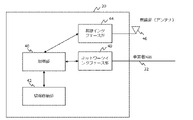
- FIG. 3 is a block diagram for explaining the configuration of the interfering device 30 shown in FIG.
- the interfering device 30 includes a control section 40 and an information storage section 42 .
- the control unit 40 includes a processor unit (CPU).
- the information storage unit 42 also has a memory, and the memory stores programs to be executed by the CPU.
- the functions of the control unit 40 are realized by the CPU of the control unit 40 proceeding with processing according to the above program.
- the information storage unit 42 further stores the ID of the device, location information, and resource information related to the frequency used for communication and the like.
- the interfering device 30 has a wireless interface section 44 .
- the wireless interface unit 44 can establish wireless communication with an external wireless device via the antenna 46 . Also, the wireless interface unit 44 can acquire the GPS information of the device via the antenna 46 .
- the interfering device 30 further includes a network interface section 48 .
- the network interface unit 48 can transmit and receive messages to and from the relay device 34 via the provider's NW 32 .
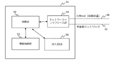
- FIG. 4 is a block diagram for explaining the configuration of the relay device 34 shown in FIG.
- the relay device 34 has a control section 50 and an information storage section 52 .
- the control unit 50 includes a processor unit (CPU).
- the information storage unit 52 also has a memory, and the memory stores programs to be executed by the CPU.
- the functions of the control unit 50 are realized by the CPU of the control unit 50 proceeding with processing according to the above program.
- This program can be recorded on a recording medium and provided to the relay device 34, and can also be provided to the relay device 34 via a network.
- the information storage unit 52 further stores information such as the content of the message to be relayed and the frequency usage table. In the frequency usage table, as will be described later, information on wireless resources used by each of the interfering devices 30 and the like are recorded.
- the relay device 34 has a network interface section 54 .
- the network interface unit 54 can transmit and receive messages to and from each of the interfering devices 30 via the operator NW 32, and can transmit and receive messages to and from the control device 14 via the public NW 36. .
- the relay device 34 further comprises a subscriber database (DB) 56.
- the subscriber DB 56 stores information about the position of the interfering device 30, such as the ID and address of the subscriber who manages the interfering device 30.
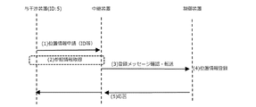
- FIG. 5 is a diagram for explaining the outline of the operation of the interference control system shown in FIG.
- location information of the interfered device 10 and the interfering devices 12 and 30 is pre-registered in the control device 14, as in the case of CBRS shown in FIG.
- the location information includes latitude and longitude, and information indicating whether the device is installed indoors or outdoors.
- FIG. 5 exemplifies the operation when the interfering device 30-5 belonging to the operator NW 32 pre-registers the location information.
- FIG. 5 specifically shows that the following operations are executed in chronological order.
- Interfering device 30-5 issues an application requesting registration of location information. This application includes the ID and the like of the interfering device 30-5.
- the relay device 34 that has received the application for registration of location information refers to the subscriber DB with the ID included in the application, and obtains information such as the address of the subscriber who manages the interfering device 30-5. Get information about the location of 30.
- the relay device 34 sets position information that matches the information acquired in the above process. Then, a registration message including the location information for which matching has been confirmed is transferred to the control device 14 . (4) Control device 14 registers the information as position information of interfering device 30-5. (5) The control device 14 replies with a message indicating the completion of registration.
- the authority to finally determine the position information of the interfering device 30 is given to the relay device 34 . Therefore, according to this system, it is possible to prevent inappropriate location information from being registered in the control device 14 due to the subscriber's intention or mistake, and the total amount of interference I suffered by the interfered device 10 can be calculated. can give a high degree of accuracy.
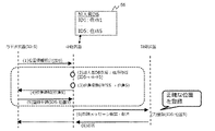
- FIG. 6 is a diagram for specifically explaining the flow of processing executed in this embodiment in order to realize the above functions.
- FIG. 6 shows that the following processes are executed in chronological order in the interference control system of this embodiment. Note that FIG. 6 exemplifies the operation when the interfering device 30-5 pre-registers the position information, as in FIG.
- the interfering device 30-5 requesting registration of location information transmits a location information query to the relay device .
- the request for location information inquiry includes the ID (eg, “ID5”) of the interfering device 30-5.
- the relay device 34 that received the location information inquiry refers to the subscriber DB 56 .
- the subscriber DB 56 stores information about the location of the interfering device 30 such as the address of the subscriber for each ID of the interfering device 30 .
- the relay device 34 acquires the address (eg, “address 5”) corresponding to the ID (eg, “ID5”) from the subscriber DB 56 as the address of the interfering device 30 .
- the relay device 34 performs position conversion on the address (for example, "address 5") and obtains converted position information (for example, "position 5") representing the position of the address.
- the converted position information is information that defines the absolute position of the address, and can be the "latitude and longitude" of the address 5, for example.
- the relay device 34 notifies the interfering device 30 that issued the position information inquiry of the converted position information (for example, "position 5") obtained by the above conversion.
- the interfering device 30 After receiving the notification, the interfering device 30 issues a registration application.
- the registration application includes information on the position of the interfering device 30 in addition to the ID (for example, “ID5”).
- the converted position information for example, "position 5" notified from the relay device 34 is used as the information regarding the position.
- the relay device 34 that receives the registration application agrees that the positional information included in the application (for example, "position 5") matches the converted position information (for example, "position 5") obtained in (3) above. Check whether Then, if the match between the two is recognized, the registration message is transferred to the control device 14 using that information as position information.
- the control device 14 that has received the transfer from the relay device 34 registers the location information (for example, "position 5") included in the registration application as location information corresponding to the ID (for example, "ID5"). do.
- the location information registered in this manner is correct information set by the relay device 34 based on the information in the subscriber DB 56 . Therefore, according to the above processing, accurate position information can be registered in the control device 14 .
- the control device 14 issues a response notifying completion of registration to the interfering device 30 requesting the registration application via the relay device 34 .
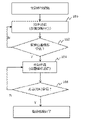
- FIG. 7 is a flowchart for explaining the flow executed by each of the interfering devices 30 included in the operator's NW in order to realize the above operations.
- the interfering device 30 requesting registration of location information first transmits its own ID (for example, "ID5") to request location information inquiry (step 100).
- its own ID for example, "ID5"
- step 102 it is determined whether or not the converted location information (for example, "location 5") corresponding to the above inquiry has been received from the relay device 34 (step 102).
- a registration application including the converted location information is sent along with the ID (step 104).
- step 106 when a response to the effect that the registration application is accepted is received (step 106), the registration processing in the interfering device 30 ends.
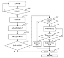
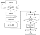
- FIG. 8 is a flowchart for explaining the flow of processing executed by the relay device 34 regarding registration of location information in this embodiment.
- the relay device 34 first determines whether or not an ID has been received from any of the interfering devices 30 (step 110).
- the reception of the ID is recognized, it is determined that the location information inquiry has been received from the interfering device 30, and the address (eg, "Address 5") corresponding to the ID (eg, "ID5") is sent from the subscriber DB 56. is obtained (step 112).
- the relay device 34 then performs position conversion on the acquired address and acquires converted position information representing the position of the address (step 114). Specifically, based on the map information stored in the information storage unit 52, "latitude and longitude" corresponding to the address are acquired as the converted position information.
- the relay device 34 transmits the converted position information to the interfering device 30 that issued the inquiry (step 116).
- the relay device 34 determines whether or not it has received a registration application from the interfering device 30 that returned the converted position information (step 118).
- step 120 If the reception of the registration application is not acknowledged after a certain waiting time, it is determined that the processing of the registration application has been stopped for some reason, and the data of the address and position information referred to in the processing of steps 112 and 114 above is deleted. Clear (step 120).
- step 122 it is determined whether or not the location information included in the application matches the converted location information acquired in step 114.
- the interfering device 30 may request the registration of uncertain information.
- the relay device 34 transmits a response to the effect that the registration is not accepted to the interfering device 30 (step 124).
- step 122 if the two pieces of information are found to match, a registration application is transmitted to the control device 14 using the converted position information as position information (step 126).
- the relay device 34 determines whether or not it has received a response regarding whether registration is possible or not from the control device 14 (step 128).
- the relay device 34 transmits the response to the interfering device 30 that issued the registration application (step 130).
- the location information of the interfering device 30 included in the operator NW 32 can be corrected and confirmed by the relay device 34 and then provided to the control device 14 . Therefore, according to the interference control system of the present embodiment, the accuracy of the position of the interfering device 30 can be reliably ensured, and the amount of interference with the interfered device 10 can be calculated accurately. .
- the relay device 34 notifies the interfering device 30 of the converted position information, and the interfering device 30 includes the converted position information in the registration application.
- the present disclosure is not so limited.
- the above notification may be abolished and the registration application issued by the interfering device 30 may be allowed to include information regarding the location set by the subscriber. If the registration is permitted when the information set by the subscriber matches the converted position information acquired by the relay device 34, the accuracy of the registration information can be properly ensured.
- the location information registered in the control device 14 may be information set by the subscriber, or may be converted location information acquired by the relay device 34 .
- Embodiment 2 Next, a second embodiment of the present disclosure will be described with reference to FIGS. 9 and 10 along with FIGS. 2 to 5.
- FIG. The interference control system of this embodiment can be realized by the hardware configuration shown in FIGS. 2 to 4, as in the case of the first embodiment. Also, the interference control system of this embodiment implements the operation described with reference to FIG. 5 by a specific method different from that of the first embodiment.
- FIG. 9 is a diagram for explaining the flow of processing executed in this embodiment to register the position information of the interfering device 30 in the control device 14. As shown in FIG. Specifically, FIG. 9 shows, in chronological order, the processing executed regarding the registration of position information in the interference control system of this embodiment.
- the subscriber DB 56 stores information on the installation location of the device together with the information on the address.
- the "position” of the "address” indicates a reference point within the premises of the address, and does not necessarily coincide with the installation point of the interfering device 30 within the premises.
- position correction when installing the interfering device 30 on the subscriber's site, the deviation between the reference point and the installation point of the device is measured, and the result is added as "position correction” information. It is recorded in the person DB 56.
- "Position correction" can be, for example, "direction deviation and distance deviation” or "latitude deviation and longitude deviation”.
- the relay device 34 that has received the location information inquiry request (1) from the interfering device 30 refers to the subscriber DB 56 based on the ID (eg, “ID5”) included in the request and obtains an address (eg, “address 5”). ) along with “position correction” information associated with the address.
- the relay device 34 then performs position conversion processing. If the "positional correction" is the deviation of the direction and the distance, first, the installation point of the device is specified from the information of the "address” and the "positional correction". Then, the installation point is converted into latitude and longitude and used as converted position information (for example, "position 5"). Also, if the "positional correction” is a difference between latitude and longitude, first, the "address” is converted into latitude and longitude, and the result reflects the "positional correction" to obtain converted position information.
- the corrected position information is notified to the interfering device 30 as converted position information.
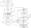
- FIG. 10 is a flowchart for explaining the flow of processing executed by the relay device 34 of this embodiment regarding registration of location information.
- steps similar to those shown in FIG. 8 are assigned common reference numerals, and their explanations are omitted or simplified.
- the relay device 34 of the present embodiment refers to the subscriber DB 56 to obtain information on the corrected position (step 122). Specifically, first, the construction information in the subscriber DB 56 is referred to, and the "position correction" information corresponding to the address is read out therefrom. The "address” and “location correction” are then converted to latitude and longitude to generate the "corrected location".
- the relay device 34 notifies the interfering device 30 of the "corrected position" information as converted position information (step 124).
- the processes after step 118 are performed in the same manner as in the case of the first embodiment. Further, in the interfering device 30 desiring to register the position information, the processing shown in FIG. 7 is executed in the same manner as in the case of the first embodiment. As a result, the control device 14 is registered with accurate position information representing the installation point within the premises. Therefore, according to the present embodiment, the calculation accuracy of the amount of interference that the interfered device 10 suffers can be further improved as compared with the case of the first embodiment.
- Embodiment 3 Next, a third embodiment of the present disclosure will be described with reference to FIGS. 11 to 13 along with FIGS. 2 to 5.
- FIG. The interference control system of this embodiment can be realized by the hardware configuration shown in FIGS. 2 to 4, as in the case of the first embodiment. Also, the interference control system of this embodiment implements the operation described with reference to FIG. 5 by a specific method different from that of the first embodiment.
- FIG. 11 is a diagram for explaining the flow of processing executed in this embodiment to register the position information of the interfering device 30 in the control device 14. As shown in FIG. Specifically, FIG. 11 shows, in chronological order, the processing executed with respect to registration of location information in the interference control system of this embodiment.
- the subscriber DB 56 stores address information and device position range information.
- This "position range” corresponds to an area in which the interfering device 30 can be installed within the premises of the address. Specifically, the east-west width of the area (eg, -a[m] to +b[m]) and the north-south width (eg, -c[m] to +d[m]) of the area with respect to the reference point of the "address” ) is stored as a “position range”.
- the installation work of the interfering device 30 is carried out at the subscriber's site, the information on the above-mentioned "positional range" is obtained and recorded in the subscriber DB 56.
- the "position range” may be determined by latitude and longitude, as well as by distance as described above.
- the relay device 34 Upon receiving location information inquiry (1) from the interfering device 30, the relay device 34 refers to the subscriber DB 56 based on the ID (eg, "ID5") included in the request, and determines the address (eg, "address 5"). Along with this, it acquires information on the "location range" associated with the address.
- the relay device 34 then performs position conversion processing. Specifically, as in the case of the first embodiment, the "address" is converted into the "position”, and the information of the "position” and the “position range” is generated as the converted position information.
- the interfering device 30 issues a registration application including the received "position” and “position range” in a message. Substantially the same processing as in Embodiment 1 is thereafter executed to register the “position” and the “position range” in the control device 14 .
- FIG. 12 is a flowchart for explaining the flow of processing executed by the relay device 34 of this embodiment regarding registration of location information.
- steps similar to those shown in FIG. 8 are assigned common reference numerals, and their explanations are omitted or simplified.
- the relay device 34 of the present embodiment refers to the subscriber DB 56 to obtain converted location information (step 130). Specifically, first, the construction information in the subscriber DB 56 is referred to, and the "location range” information corresponding to the address is read out therefrom. Then, the "address" is transformed into the "location” to generate transformed location information including the "location” and the "location range”.
- the relay device 34 notifies the interfering device 30 of the converted position information including the "position” and the "position range” (step 132).
- the relay device 34 acknowledges the reception of the registration application in step 118, the "position" and the “position range” included in the registration application are replaced with the "position” and the “position” obtained in step 130 above. It is determined whether or not it matches the position range. After that, in the relay device 34, the processing after step 124 or 126 is performed in the same manner as in the case of the first embodiment according to the result of the determination.
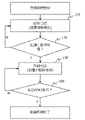
- FIG. 13 is a flowchart for explaining the flow of processing executed by the interfering device 30 regarding registration of location information in this embodiment.
- the same steps as those shown in FIG. 7 are denoted by common reference numerals, and description thereof will be omitted or simplified.
- step 136 it is determined whether or not converted position information including "position” and "position range” has been received from the relay device 34.
- a registration application including the "position” and “position range” contained therein is transmitted to the relay device 34 (step 138).
- the "position” and “position range” thus transmitted are registered in the control device 14 after confirmation by the relay device 34 as described above.
- the processing of the interfering device 30 regarding location registration ends.
- the "position" and “position range” of the device can be registered in the control device 14.
- the position of the interfering device 30 may be relocated within the "position range".
- the amount of interference can be calculated with the width of the "positional range”.
- Embodiment 4 Next, a fourth embodiment of the present disclosure will be described with reference to FIGS. 14 to 18 together with FIGS. 2 to 5.
- FIG. The interference control system of this embodiment can be realized by the hardware configuration shown in FIGS. 2 to 4, as in the case of the first embodiment. Also, the interference control system of this embodiment implements the operation described with reference to FIG. 5 by a specific method different from that of the first embodiment.
- FIG. 14 is a diagram for explaining the flow of processing executed in this embodiment to register the position information of the interfering device 30 in the control device 14. As shown in FIG. Specifically, FIG. 14 shows how the interference control system of the present embodiment executes the following processes in chronological order regarding the registration of position information.
- the converted position information obtained by conversion from the ID is temporarily returned from the relay device 34 to the interfering device 30.
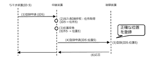
- the present embodiment is characterized in that the relay device 34 acquires the position information from the ID and directly transmits it to the control device 14 without returning it to the interfering device 30 .
- an interfering device 30 requesting position registration transmits a registration application including an ID to the relay device 34 .
- the relay device 34 that receives the registration application refers to the subscriber DB 56 and enters the address (eg, "address 5") corresponding to the ID (eg, "ID5"). get.
- the relay device 34 further converts the address into a position (for example, "position 5") as in the case of the first embodiment.
- the relay device 34 of the present embodiment transmits a registration application to the control device 14 with a message including an ID (eg "ID5") and a location (eg "location 5").
- the control device 14 registers the location information included in the message sent from the relay device 34 in association with the interfering device 30 having the ID included in the message. Thereby, the accurate position information set by the relay device 34 is registered in the control device 14 . (6) Thereafter, a response is returned from the control device 14 to the interfering device 30 via the relay device 34, and the location registration processing in the present embodiment ends.
- FIG. 15 is a flowchart for explaining the flow of processing executed by the interfering device 30 regarding registration of location information in this embodiment.
- the same steps as those shown in FIG. 7 are denoted by common reference numerals, and the description thereof will be omitted or simplified.
- an interfering device 30 requesting location registration transmits an ID as a registration application (step 140). Thereafter, when a response is received in step 106, the processing of the interfering device 30 ends.
- FIG. 16 is a flowchart for explaining the flow of processing executed by the relay device 34 of this embodiment regarding registration of location information.
- steps similar to those shown in FIG. 8 are assigned common reference numerals, and their explanations are omitted or simplified.
- the relay device 34 of the present embodiment determines whether or not a registration application including an ID has been received from the interfering device 30 (step 142). Then, when the reception of such a registration application is accepted, "location information" is acquired by the processing of steps 112 and 114, as in the case of the first embodiment.
- the registration application message containing the ID is converted into a message containing "location information" along with the ID (step 144).
- step 126 the processes from step 126 onward are executed in the same manner as in the first embodiment. Then, in step 120, when the reference data is cleared, the processing in relay device 34 ends.
- the relay device 34 directly transmits the position information acquired by conversion from the ID to the control device 14 without returning it to the interfering device 30 .
- the processing of the interfering device 30 and the processing of the relay device 34 are reduced compared to the first embodiment. can be greatly simplified.
- the technology in which the relay device 34 directly transmits the position information to the control device 14 is combined with the registration information of the first embodiment, but the present disclosure is limited to this. is not.
- FIG. 17 shows the operation when combining the technology in which the relay device 34 directly transmits the position information to the control device 14 with the registration information of the second embodiment, that is, the "correction position".
- the processing of the interfering device 30 and the processing of the relay device 34 are reduced compared to the case of the second embodiment. can be greatly simplified.
- FIG. 18 shows the operation when combining the technology in which the relay device 34 directly transmits the location information to the control device 14 with the registration information of the third embodiment, that is, the location information including the "location” and the "location range". ing.
- the processing of the interfering device 30 and the processing of the relay device 34 are reduced compared to the case of the third embodiment. can be greatly simplified.
- Embodiment 5 Next, a fifth embodiment of the present disclosure will be described with reference to FIGS. 19 to 21 together with FIGS. 2 to 5.
- FIG. The interference control system of this embodiment can be realized by the hardware configuration shown in FIGS. 2 to 4, as in the case of the first embodiment. Also, the interference control system of this embodiment implements the operation described with reference to FIG. 5 by a specific method different from that of the first embodiment.
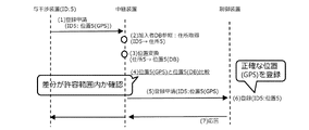
- FIG. 19 is a diagram for explaining the flow of processing executed in this embodiment for registering in the control device 14 the position information of the interfering device 30, which has a function of detecting its own position using GPS. It is a diagram. Specifically, FIG. 19 shows how the interference control system of the present embodiment executes the following processes in chronological order regarding the registration of position information.
- the relay device 34 is given the authority to set the position information of the interfering device 30 .
- the interfering device 30 has a function of detecting its own position using GPS, it is characterized in that the authority to set the position information is given to the interfering device 30. is doing.
- an interfering device 30 requesting position registration uses an ID (for example, “ID5”) and a position acquired using GPS (for example, “position 5 (GPS) , hereinafter referred to as “GPS information”) is transmitted to the relay device 34 .
- ID5 for example, “ID5”
- GPS position 5
- the relay device 34 that receives the registration application refers to the subscriber DB 56 and enters the address (eg, "address 5") corresponding to the ID (eg, "ID5"). get. (3) The relay device 34 further converts the address into a position (for example, "position 5 (DB)”) as in the case of the first embodiment. (4) Next, the relay device 34 acquires the GPS information (eg, “location 5 (GPS)”) received from the interfering device 30 and the acquired location (eg, “location 5 (DB)” by referring to the subscriber DB 56). ). Then, when it is recognized that the two match, more specifically, when the difference between the two falls within a predetermined allowable range, the position information received from the interfering device 30 is recognized as correct.
- GPS location 5
- the relay device 34 Upon recognizing that the GPS information received from the interfering device 30 is correct, the relay device 34 transmits a registration application including an ID (eg, "ID5") and GPS information (eg, "Position 5 (GPS)" to the control device. Send to 14.
- ID eg, "ID5"
- GPS information eg, "Position 5 (GPS)
- the control device 14 registers the GPS information (for example, "Position 5 (GPS)") sent from the relay device 34 in association with the ID included in the registration application. As a result, accurate position information obtained using GPS is registered in the control device 14 .
- GPS Position 5
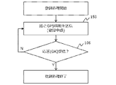
- FIG. 20 is a flowchart for explaining the flow of processing executed by the interfering device 30 regarding registration of location information in this embodiment.
- steps similar to those shown in FIG. 7 are denoted by common reference numerals, and description thereof will be omitted or simplified.
- the interfering device 30 requesting location registration transmits a registration application including GPS information together with an ID (step 150). Thereafter, when a response is received in step 106, the processing of the interfering device 30 ends.
- FIG. 21 is a flowchart for explaining the flow of processing executed by the relay device 34 of this embodiment regarding registration of location information.
- the steps similar to those shown in FIG. 8 are denoted by the same reference numerals, and the description thereof will be omitted or simplified.
- the relay device 34 of the present embodiment determines whether or not a registration application containing GPS information together with an ID has been received from the interfering device 30 (step 152). Then, when the reception of such a registration application is recognized, the "location information (DB)" based on the subscriber DB 56 is acquired by the processing of steps 112 and 114, as in the case of the first embodiment.
- DB location information
- the relay device 34 determines whether or not the GPS information and the location information (DB) match (step 154).
- DB location information
- the difference between the two falls within a preset allowable range, it is determined that the two match.
- This allowable range may be set based on the range in which the device can move within the site, such as the "positional range" described in the third embodiment. If it is determined in step 154 that the two do not match, there is a possibility that the GPS information is incorrect.
- step 126 the processes from step 126 onward are executed in the same manner as in the first embodiment. Then, in step 120, when the reference data is cleared, the processing in relay device 34 ends.
- the GPS information can be registered in the control device 14 as position information.
- the GPS information accurately represents the location of the interfering device 30 and is generally more accurate than the location information (DB) estimated by the repeater 34 based on the subscriber DB 56 . Therefore, according to the present embodiment, the accuracy of registered position information can be further improved as compared with the first to fourth embodiments.
Landscapes
- Engineering & Computer Science (AREA)
- Computer Networks & Wireless Communication (AREA)
- Signal Processing (AREA)
- Mobile Radio Communication Systems (AREA)
Abstract
Description
プロセッサユニットと、
前記プロセッサユニットが実行するプログラムを格納したメモリと、
前記与干渉装置夫々の位置に関する情報を格納した加入者データベースとを備え、
前記プロセッサユニットは、
事業者ネットワークに配置された与干渉装置から、当該与干渉装置のIDを含む登録申請を受け付ける処理と、
前記登録申請を受けて、前記IDについて前記加入者データベースに格納されている情報と合致する位置情報を設定する位置情報生成処理と、
前記位置情報を、登録を求めて前記制御装置に送信する処理と、
を実行することが望ましい。
事業者ネットワークに配置された与干渉装置から、当該与干渉装置のIDを含む登録申請を受け付けるステップと、
前記登録申請を受けて、前記与干渉装置夫々の位置に関する情報を格納した加入者データベースに格納されている情報と合致する位置情報を設定するステップと、
前記位置情報を、登録を求めて前記制御装置に送信するステップと、
を含むことが望ましい。
プロセッサユニットと、
前記プロセッサユニットが実行するプログラムを格納したメモリと、
前記与干渉装置夫々の位置に関する情報を格納した加入者データベースとを備え、
前記プロセッサユニットは、
事業者ネットワークに配置された与干渉装置から、当該与干渉装置のIDを含む登録申請を受け付ける処理と、
前記登録申請を受けて、前記IDについて前記加入者データベースに格納されている情報と合致する位置情報を設定する位置情報生成処理と、
前記位置情報を、登録を求めて前記制御装置に送信する処理と、
を実行することが望ましい。
プロセッサユニットに、
事業者ネットワークに配置された与干渉装置から、当該与干渉装置のIDを含む登録申請を受け付ける処理と、
前記登録申請を受けて、前記与干渉装置夫々の位置に関する情報を格納した加入者データベースに格納されている情報と合致する位置情報を設定するステップと、
前記位置情報を、登録を求めて前記制御装置に送信する処理と、
を実行させるプログラムを含むことが望ましい。
[実施の形態1の比較例]
図1は、CBRSを用いた干渉制御システムの概要を説明するための図である。以下、本開示の実施の形態1の干渉制御システムの比較例として、このシステムの構成および動作を説明する。
1.装置ID=CBSD5
2.装置の設置位置の緯度および経度
3.装置が屋内設置であるか屋外設置であるかを示す情報
4.装置のアンテナ利得
1.通信に使用したい周波数チャネル
2.信号の送信に用いたい送信電力
図2は、本開示の実施の形態1の干渉制御システムの構成を示す。図2に示す干渉制御システムでは、図1に示すCBRSの構成に、特定の通信事業者が提供する光アクセスサービスが組み込まれている。尚、図2において、図1に示す要素と同一の要素については、共通する符号を付してその説明を省略または簡略する。
(1)与干渉装置30-5が位置情報の登録を求める申請を発する。この申請には、与干渉装置30-5のID等が含まれる。
(4)制御装置14は、その情報を与干渉装置30-5の位置情報として登録する。
(5)制御装置14は、登録完了を知らせるメッセージを応答として返信する。
図6は、上記の機能を実現するために、本実施形態において実行される処理の流れを具体的に説明するための図である。図6は、本実施形態の干渉制御システムで、以下の処理が時系列で実行されることを示している。尚、図6は、図5と同様に、与干渉装置30-5が、位置情報を事前登録する際の動作を例示している。
(3)次いで、中継装置34は、その住所(例えば「住所5」)に位置変換を施して、その住所の位置を表す変換位置情報(例えば「位置5」)を取得する。変換位置情報は、住所の絶対的な位置を定めた情報であり、例えば、住所5の「緯度および経度」とすることができる。
(4)中継装置34は、上記の変換により取得した変換位置情報(例えば「位置5」)を、位置情報照会を発した与干渉装置30に通知する。
(8)上記の登録が終わると、制御装置14は、中継装置34を介して、登録の申請を求めた与干渉装置30に向けて、登録完了を知らせる応答を発する。
ところで、上述した実施の形態1では、中継装置34から与干渉装置30に変換位置情報を通知し、与干渉装置30が、その変換位置情報を登録申請に含めることとしている。しかしながら、本開示はこれに限定されるものではない。例えば、上記の通知を廃止して、与干渉装置30が発する登録申請には、加入者が設定した位置に関する情報を含めることを認めても良い。加入者が設定した情報が、中継装置34が取得した変換位置情報と合致する場合に登録を認めることとすれば、登録情報の正確性は適正に担保することができる。尚、この場合、制御装置14に登録される位置情報は、加入者が設定した情報であってもよいし、中継装置34が取得した変換位置情報であってもよい。
次に、図2乃至図5と共に、図9および図10を参照して本開示の実施の形態2について説明する。本実施形態の干渉制御システムは、実施の形態1の場合と同様に、図2乃至図4に示すハードウェア構成により実現することができる。また、本実施形態の干渉制御システムは、図5を参照して説明した動作を、実施の形態1の場合とは異なる具体的手法で実現する。
図9は、与干渉装置30の位置情報を制御装置14に登録するために本実施形態において実行される処理の流れを説明するための図である。図9は、具体的には、本実施形態の干渉制御システムで、位置情報の登録に関して実行される処理を時系列で示している。
尚、中継装置34から与干渉装置30への変換位置情報の通知を廃止して、加入者が設定した位置に関する情報と中継装置34が取得した変換位置情報とが合致する場合に登録を認めるように変形することが可能である点は、実施の形態1の場合と同様である。
次に、図2乃至図5と共に、図11乃至図13を参照して本開示の実施の形態3について説明する。本実施形態の干渉制御システムは、実施の形態1の場合と同様に、図2乃至図4に示すハードウェア構成により実現することができる。また、本実施形態の干渉制御システムは、図5を参照して説明した動作を、実施の形態1の場合とは異なる具体的手法で実現する。
図11は、与干渉装置30の位置情報を制御装置14に登録するために本実施形態において実行される処理の流れを説明するための図である。図11は、具体的には、本実施形態の干渉制御システムで、位置情報の登録に関して実行される処理を時系列で示している。
尚、中継装置34から与干渉装置30への変換位置情報の通知を廃止して、加入者が設定した位置に関する情報と中継装置34が取得した変換位置情報とが合致する場合に登録を認めるように変形することが可能である点は、実施の形態1の場合と同様である。
次に、図2乃至図5と共に、図14乃至図18を参照して本開示の実施の形態4について説明する。本実施形態の干渉制御システムは、実施の形態1の場合と同様に、図2乃至図4に示すハードウェア構成により実現することができる。また、本実施形態の干渉制御システムは、図5を参照して説明した動作を、実施の形態1の場合とは異なる具体的手法で実現する。
図14は、与干渉装置30の位置情報を制御装置14に登録するために本実施形態において実行される処理の流れを説明するための図である。図14は、具体的には、本実施形態の干渉制御システムで、位置情報の登録に関して以下の処理が時系列で実行される様子を示している。
(3)中継装置34は、更に、実施の形態1の場合と同様に、住所を位置(例えば「位置5」)に変換する。
(6)以後、制御装置14から中継装置34を介して与干渉装置30に応答が返信されることにより、本実施形態における位置登録の処理が終了する。
次に、図2乃至図5と共に、図19乃至図21を参照して本開示の実施の形態5について説明する。本実施形態の干渉制御システムは、実施の形態1の場合と同様に、図2乃至図4に示すハードウェア構成により実現することができる。また、本実施形態の干渉制御システムは、図5を参照して説明した動作を、実施の形態1の場合とは異なる具体的手法で実現する。
図19は、GPSを利用して自らの位置を検知する機能を有する与干渉装置30の位置情報を、制御装置14に登録するために本実施形態において実行される処理の流れを説明するための図である。図19は、具体的には、本実施形態の干渉制御システムで、位置情報の登録に関して以下の処理が時系列で実行される様子を示している。
(3)中継装置34は、更に、実施の形態1の場合と、同様に、住所を位置(例えば「位置5(DB)」)に変換する。
(4)次いで、中継装置34は、与干渉装置30から受け取ったGPS情報(例えば「位置5(GPS)」)と、加入者DB56を参照して取得した位置(例えば「位置5(DB)」)とを比較する。そして、両者が合致すると認められる場合、より具体的には、両者の差が予め定めておいた許容範囲に収まる場合は、与干渉装置30から受け取った位置情報を正しいものとして認識する。
12、12-1~12-5、30、30-1~30-3 与干渉装置
14 制御装置
32 事業者ネットワーク(事業者NW)
34 中継装置
36 公衆ネットワーク(公衆NW)
50 制御部
52 情報格納部
56 加入者データベース(DB)
Claims (8)
- 無線通信を行う複数の与干渉装置が無線通信を行う被干渉装置に与える干渉量を計算するために、前記複数の与干渉装置夫々の位置情報を、前記干渉量の計算を担う制御装置に登録させる無線通信の干渉制御システムであって、
プロセッサユニットと、
前記プロセッサユニットが実行するプログラムを格納したメモリと、
前記与干渉装置夫々の位置に関する情報を格納した加入者データベースとを備え、
前記プロセッサユニットは、
事業者ネットワークに配置された与干渉装置から、当該与干渉装置のIDを含む登録申請を受け付ける処理と、
前記登録申請を受けて、前記IDについて前記加入者データベースに格納されている情報と合致する位置情報を設定する位置情報生成処理と、
前記位置情報を、登録を求めて前記制御装置に送信する処理と、
を実行する無線通信の干渉制御システム。 - 前記プロセッサユニットは、
事業者ネットワークに配置された与干渉装置から、当該与干渉装置のIDを含む位置情報照会を受け付ける処理と、
前記位置情報照会を受けて、前記IDについて前記加入者データベースに格納されている住所を特定するDB参照処理と、
前記住所に位置変換を施して当該住所の位置を表す変換位置情報を取得する処理と、
前記変換位置情報を、前記位置情報照会を発した与干渉装置に戻す処理とを更に実行し、
前記登録申請は、前記IDと共に、当該登録申請を発した与干渉装置の位置に関する情報を含んでおり、
前記位置情報生成処理は、前記登録申請に含まれる前記位置に関する情報が、前記変換位置情報と合致する場合に、当該位置に関する情報または前記変換位置情報を前記位置情報とする処理を含む請求項1に記載の無線通信の干渉制御システム。 - 前記加入者データベースは、個々の住所の位置と、個々の住所における前記与干渉装置の設置点とのずれを表す位置補正の情報を格納しており、
前記DB参照処理は、前記IDについて前記加入者データベースに格納されている前記位置補正を特定する処理を含み、
前記変換位置情報は、前記住所の基準点に前記位置補正を反映させた補正位置を表すものである請求項2に記載の無線通信の干渉制御システム。 - 前記加入者データベースは、前記与干渉装置の設置が可能な個々の住所における位置範囲の情報を格納しており、
前記DB参照処理は、前記IDについて前記加入者データベースに格納されている前記位置範囲を特定する処理を含み、
前記変換位置情報は、前記住所の位置と当該住所の位置範囲とを表すものである請求項2に記載の無線通信の干渉制御システム。 - 前記登録申請は、前記IDと共に、与干渉装置がGPSを利用して取得した自らの位置を表すGPS情報を含み、
前記位置情報生成処理は、前記登録申請に含まれる前記GPS情報が、前記加入者データベースに格納されている情報と合致する場合に、当該GPS情報を前記位置情報とする処理を含む請求項1に記載の無線通信の干渉制御システム。 - 無線通信を行う複数の与干渉装置が無線通信を行う被干渉装置に与える干渉量を計算するために、前記複数の与干渉装置夫々の位置情報を、前記干渉量の計算を担う制御装置に登録させる無線通信の干渉制御方法であって、
事業者ネットワークに配置された与干渉装置から、当該与干渉装置のIDを含む登録申請を受け付けるステップと、
前記登録申請を受けて、前記与干渉装置夫々の位置に関する情報を格納した加入者データベースに格納されている情報と合致する位置情報を設定するステップと、
前記位置情報を、登録を求めて前記制御装置に送信するステップと、
を含む無線通信の干渉制御方法。 - 無線通信を行う複数の与干渉装置が無線通信を行う被干渉装置に与える干渉量を計算するために、前記複数の与干渉装置夫々の位置情報を、前記干渉量の計算を担う制御装置に登録させる無線通信の中継装置であって、
プロセッサユニットと、
前記プロセッサユニットが実行するプログラムを格納したメモリと、
前記与干渉装置夫々の位置に関する情報を格納した加入者データベースとを備え、
前記プロセッサユニットは、
事業者ネットワークに配置された与干渉装置から、当該与干渉装置のIDを含む登録申請を受け付ける処理と、
前記登録申請を受けて、前記IDについて前記加入者データベースに格納されている情報と合致する位置情報を設定する位置情報生成処理と、
前記位置情報を、登録を求めて前記制御装置に送信する処理と、
を実行する無線通信の中継装置。 - 請求項7に記載の中継装置を実現するための無線通信の干渉制御用プログラムであって、
プロセッサユニットに、
事業者ネットワークに配置された与干渉装置から、当該与干渉装置のIDを含む登録申請を受け付ける処理と、
前記登録申請を受けて、前記与干渉装置夫々の位置に関する情報を格納した加入者データベースに格納されている情報と合致する位置情報を設定するステップと、
前記位置情報を、登録を求めて前記制御装置に送信する処理と、
を実行させるプログラムを含む無線通信の干渉制御用プログラム。
Priority Applications (3)
| Application Number | Priority Date | Filing Date | Title |
|---|---|---|---|
| PCT/JP2021/008278 WO2022185461A1 (ja) | 2021-03-03 | 2021-03-03 | 無線通信の干渉制御システム、干渉制御方法、中継装置および干渉制御用プログラム |
| JP2023503270A JP7619433B2 (ja) | 2021-03-03 | 2021-03-03 | 無線通信の干渉制御システム、干渉制御方法、中継装置および干渉制御用プログラム |
| US18/278,005 US12615518B2 (en) | 2021-03-03 | 2021-03-03 | Interference control system, interference control method, link-up device and program for interference control for wireless communications |
Applications Claiming Priority (1)
| Application Number | Priority Date | Filing Date | Title |
|---|---|---|---|
| PCT/JP2021/008278 WO2022185461A1 (ja) | 2021-03-03 | 2021-03-03 | 無線通信の干渉制御システム、干渉制御方法、中継装置および干渉制御用プログラム |
Publications (1)
| Publication Number | Publication Date |
|---|---|
| WO2022185461A1 true WO2022185461A1 (ja) | 2022-09-09 |
Family
ID=83155178
Family Applications (1)
| Application Number | Title | Priority Date | Filing Date |
|---|---|---|---|
| PCT/JP2021/008278 Ceased WO2022185461A1 (ja) | 2021-03-03 | 2021-03-03 | 無線通信の干渉制御システム、干渉制御方法、中継装置および干渉制御用プログラム |
Country Status (3)
| Country | Link |
|---|---|
| US (1) | US12615518B2 (ja) |
| JP (1) | JP7619433B2 (ja) |
| WO (1) | WO2022185461A1 (ja) |
Families Citing this family (2)
| Publication number | Priority date | Publication date | Assignee | Title |
|---|---|---|---|---|
| US12615518B2 (en) * | 2021-03-03 | 2026-04-28 | Ntt, Inc. | Interference control system, interference control method, link-up device and program for interference control for wireless communications |
| WO2022259389A1 (ja) * | 2021-06-08 | 2022-12-15 | 日本電信電話株式会社 | 無線通信の干渉制御システム、干渉制御方法、中継装置および干渉制御用プログラム |
Citations (4)
| Publication number | Priority date | Publication date | Assignee | Title |
|---|---|---|---|---|
| JP2006166405A (ja) * | 2004-11-12 | 2006-06-22 | Couei Corp | 位置情報算出システム、レピータ局、移動体通信端末、プログラム、記録媒体、複製部および位置情報算出方法 |
| JP2010219753A (ja) * | 2009-03-16 | 2010-09-30 | Kddi Corp | 無線通信システム、基地局装置、サーバ、基地局装置の設置位置確認方法 |
| WO2011021431A1 (ja) * | 2009-08-20 | 2011-02-24 | 住友電気工業株式会社 | 基地局装置、通信システム、通信方法、及びプログラム |
| WO2020189022A1 (ja) * | 2019-03-15 | 2020-09-24 | ソニー株式会社 | 情報処理装置、情報処理方法、及び通信装置 |
Family Cites Families (5)
| Publication number | Priority date | Publication date | Assignee | Title |
|---|---|---|---|---|
| CN101682900B (zh) * | 2007-06-01 | 2013-05-29 | 松下电器产业株式会社 | 通信系统、无线通信终端、位置推定装置、通信中继装置和连接站 |
| EP3226631B1 (en) * | 2014-11-27 | 2019-09-18 | Kyocera Corporation | Communication system and user terminal |
| JP6316990B2 (ja) * | 2015-02-10 | 2018-04-25 | 京セラ株式会社 | ユーザ端末、プロセッサ及び移動通信システム |
| US9680617B2 (en) * | 2015-03-20 | 2017-06-13 | Acer Incorporated | Method of transmitting reference signal in unlicensed spectrum for LTE-LAA system and wireless device using the same |
| US12615518B2 (en) * | 2021-03-03 | 2026-04-28 | Ntt, Inc. | Interference control system, interference control method, link-up device and program for interference control for wireless communications |
-
2021
- 2021-03-03 US US18/278,005 patent/US12615518B2/en active Active
- 2021-03-03 JP JP2023503270A patent/JP7619433B2/ja active Active
- 2021-03-03 WO PCT/JP2021/008278 patent/WO2022185461A1/ja not_active Ceased
Patent Citations (4)
| Publication number | Priority date | Publication date | Assignee | Title |
|---|---|---|---|---|
| JP2006166405A (ja) * | 2004-11-12 | 2006-06-22 | Couei Corp | 位置情報算出システム、レピータ局、移動体通信端末、プログラム、記録媒体、複製部および位置情報算出方法 |
| JP2010219753A (ja) * | 2009-03-16 | 2010-09-30 | Kddi Corp | 無線通信システム、基地局装置、サーバ、基地局装置の設置位置確認方法 |
| WO2011021431A1 (ja) * | 2009-08-20 | 2011-02-24 | 住友電気工業株式会社 | 基地局装置、通信システム、通信方法、及びプログラム |
| WO2020189022A1 (ja) * | 2019-03-15 | 2020-09-24 | ソニー株式会社 | 情報処理装置、情報処理方法、及び通信装置 |
Also Published As
| Publication number | Publication date |
|---|---|
| US20240129747A1 (en) | 2024-04-18 |
| JP7619433B2 (ja) | 2025-01-22 |
| US12615518B2 (en) | 2026-04-28 |
| JPWO2022185461A1 (ja) | 2022-09-09 |
Similar Documents
| Publication | Publication Date | Title |
|---|---|---|
| JP5826806B2 (ja) | 無線移動通信ネットワークにおいて複数の移動局を用いて基地局の所在位置を決定する方法及び装置 | |
| US10568062B2 (en) | Positioning for WLANs and other wireless networks | |
| JP5583801B2 (ja) | フェムト基地局ロケーションを決定するための方法および装置 | |
| JP4016787B2 (ja) | 移動通信ネットワークにおける測位システム | |
| JP6189538B2 (ja) | 屋内ロケーションのセキュリティおよびプライバシー | |
| US8681741B1 (en) | Autonomous hybrid WLAN/GPS location self-awareness | |
| US20180246218A1 (en) | Positioning method in mobile network, base station, and mobile terminal | |
| EP4185884B1 (en) | Crowd sourced rtt-based positioning | |
| CN110892761B (zh) | 远程用户设备的定位方法和系统 | |
| US20080318596A1 (en) | Method and Apparatus for Determining the Position of a Base Station in a Cellular Communication Network | |
| US20120088521A1 (en) | Mobile communication method, mobile communication system, mobile switching center, server device, and radio base station | |
| JPH11272698A (ja) | 情報提供システム | |
| WO2022185461A1 (ja) | 無線通信の干渉制御システム、干渉制御方法、中継装置および干渉制御用プログラム | |
| EP3262875B1 (en) | Positioning system and method for determining the location of a mobile communication device | |
| WO2005039223A1 (ja) | 位置情報通知システムおよび方法、端末位置特定装置ならびにプライバシチェック装置 | |
| US10051409B2 (en) | Positioning systems and methods for determining the location of a mobile communication device | |
| US20080311931A1 (en) | Location support in wireless networks | |
| KR20210144375A (ko) | 단말 위치 결정 방법 | |
| WO2012097710A1 (zh) | 一种请求获取HeNB的定位信息的方法、装置及系统 | |
| KR101448126B1 (ko) | 호설정에 연동한 자동 위치 정보 전송 방법 및 시스템 | |
| WO2022259389A1 (ja) | 無線通信の干渉制御システム、干渉制御方法、中継装置および干渉制御用プログラム | |
| CN102480676A (zh) | 一种定位信息的传输方法及系统 | |
| JP7526327B2 (ja) | 情報処理装置、情報処理システム、情報処理方法及びプログラム | |
| KR101784215B1 (ko) | Lte 망을 이용하는 이동단말이 전원 off이거나 음영지역에 위치하는 경우를 포함하는 위치 측위 방법 및 시스템 | |
| CN111246387B (zh) | 一种宽带网络网关获取位置信息的方法和系统 |
Legal Events
| Date | Code | Title | Description |
|---|---|---|---|
| 121 | Ep: the epo has been informed by wipo that ep was designated in this application |
Ref document number: 21929037 Country of ref document: EP Kind code of ref document: A1 |
|
| WWE | Wipo information: entry into national phase |
Ref document number: 18278005 Country of ref document: US |
|
| WWE | Wipo information: entry into national phase |
Ref document number: 2023503270 Country of ref document: JP |
|
| NENP | Non-entry into the national phase |
Ref country code: DE |
|
| 122 | Ep: pct application non-entry in european phase |
Ref document number: 21929037 Country of ref document: EP Kind code of ref document: A1 |