WO2022181704A1 - 磁気記録媒体、磁気テープカートリッジおよび磁気記録再生装置 - Google Patents
磁気記録媒体、磁気テープカートリッジおよび磁気記録再生装置 Download PDFInfo
- Publication number
- WO2022181704A1 WO2022181704A1 PCT/JP2022/007650 JP2022007650W WO2022181704A1 WO 2022181704 A1 WO2022181704 A1 WO 2022181704A1 JP 2022007650 W JP2022007650 W JP 2022007650W WO 2022181704 A1 WO2022181704 A1 WO 2022181704A1
- Authority
- WO
- WIPO (PCT)
- Prior art keywords
- magnetic
- recording medium
- magnetic recording
- magnetic layer
- iron oxide
- Prior art date
- Legal status (The legal status is an assumption and is not a legal conclusion. Google has not performed a legal analysis and makes no representation as to the accuracy of the status listed.)
- Ceased
Links
Classifications
-
- G—PHYSICS
- G11—INFORMATION STORAGE
- G11B—INFORMATION STORAGE BASED ON RELATIVE MOVEMENT BETWEEN RECORD CARRIER AND TRANSDUCER
- G11B5/00—Recording by magnetisation or demagnetisation of a record carrier; Reproducing by magnetic means; Record carriers therefor
- G11B5/62—Record carriers characterised by the selection of the material
- G11B5/64—Record carriers characterised by the selection of the material comprising only the magnetic material without bonding agent
- G11B5/66—Record carriers characterised by the selection of the material comprising only the magnetic material without bonding agent the record carriers consisting of several layers
- G11B5/676—Record carriers characterised by the selection of the material comprising only the magnetic material without bonding agent the record carriers consisting of several layers having magnetic layers separated by a nonmagnetic layer, e.g. antiferromagnetic layer, Cu layer or coupling layer
-
- G—PHYSICS
- G11—INFORMATION STORAGE
- G11B—INFORMATION STORAGE BASED ON RELATIVE MOVEMENT BETWEEN RECORD CARRIER AND TRANSDUCER
- G11B23/00—Record carriers not specific to the method of recording or reproducing; Accessories, e.g. containers, specially adapted for co-operation with the recording or reproducing apparatus ; Intermediate mediums; Apparatus or processes specially adapted for their manufacture
- G11B23/02—Containers; Storing means both adapted to cooperate with the recording or reproducing means
- G11B23/037—Single reels or spools
-
- G—PHYSICS
- G11—INFORMATION STORAGE
- G11B—INFORMATION STORAGE BASED ON RELATIVE MOVEMENT BETWEEN RECORD CARRIER AND TRANSDUCER
- G11B5/00—Recording by magnetisation or demagnetisation of a record carrier; Reproducing by magnetic means; Record carriers therefor
- G11B5/62—Record carriers characterised by the selection of the material
- G11B5/68—Record carriers characterised by the selection of the material comprising one or more layers of magnetisable material homogeneously mixed with a bonding agent
- G11B5/70—Record carriers characterised by the selection of the material comprising one or more layers of magnetisable material homogeneously mixed with a bonding agent on a base layer
-
- G—PHYSICS
- G11—INFORMATION STORAGE
- G11B—INFORMATION STORAGE BASED ON RELATIVE MOVEMENT BETWEEN RECORD CARRIER AND TRANSDUCER
- G11B5/00—Recording by magnetisation or demagnetisation of a record carrier; Reproducing by magnetic means; Record carriers therefor
- G11B5/62—Record carriers characterised by the selection of the material
- G11B5/68—Record carriers characterised by the selection of the material comprising one or more layers of magnetisable material homogeneously mixed with a bonding agent
- G11B5/70—Record carriers characterised by the selection of the material comprising one or more layers of magnetisable material homogeneously mixed with a bonding agent on a base layer
- G11B5/706—Record carriers characterised by the selection of the material comprising one or more layers of magnetisable material homogeneously mixed with a bonding agent on a base layer characterised by the composition of the magnetic material
-
- G—PHYSICS
- G11—INFORMATION STORAGE
- G11B—INFORMATION STORAGE BASED ON RELATIVE MOVEMENT BETWEEN RECORD CARRIER AND TRANSDUCER
- G11B5/00—Recording by magnetisation or demagnetisation of a record carrier; Reproducing by magnetic means; Record carriers therefor
- G11B5/62—Record carriers characterised by the selection of the material
- G11B5/68—Record carriers characterised by the selection of the material comprising one or more layers of magnetisable material homogeneously mixed with a bonding agent
- G11B5/70—Record carriers characterised by the selection of the material comprising one or more layers of magnetisable material homogeneously mixed with a bonding agent on a base layer
- G11B5/714—Record carriers characterised by the selection of the material comprising one or more layers of magnetisable material homogeneously mixed with a bonding agent on a base layer characterised by the dimension of the magnetic particles
-
- G—PHYSICS
- G11—INFORMATION STORAGE
- G11B—INFORMATION STORAGE BASED ON RELATIVE MOVEMENT BETWEEN RECORD CARRIER AND TRANSDUCER
- G11B5/00—Recording by magnetisation or demagnetisation of a record carrier; Reproducing by magnetic means; Record carriers therefor
- G11B5/62—Record carriers characterised by the selection of the material
- G11B5/73—Base layers, i.e. all non-magnetic layers lying under a lowermost magnetic recording layer, e.g. including any non-magnetic layer in between a first magnetic recording layer and either an underlying substrate or a soft magnetic underlayer
-
- G—PHYSICS
- G11—INFORMATION STORAGE
- G11B—INFORMATION STORAGE BASED ON RELATIVE MOVEMENT BETWEEN RECORD CARRIER AND TRANSDUCER
- G11B5/00—Recording by magnetisation or demagnetisation of a record carrier; Reproducing by magnetic means; Record carriers therefor
- G11B5/62—Record carriers characterised by the selection of the material
- G11B5/73—Base layers, i.e. all non-magnetic layers lying under a lowermost magnetic recording layer, e.g. including any non-magnetic layer in between a first magnetic recording layer and either an underlying substrate or a soft magnetic underlayer
- G11B5/735—Base layers, i.e. all non-magnetic layers lying under a lowermost magnetic recording layer, e.g. including any non-magnetic layer in between a first magnetic recording layer and either an underlying substrate or a soft magnetic underlayer characterised by the back layer
-
- G—PHYSICS
- G11—INFORMATION STORAGE
- G11B—INFORMATION STORAGE BASED ON RELATIVE MOVEMENT BETWEEN RECORD CARRIER AND TRANSDUCER
- G11B5/00—Recording by magnetisation or demagnetisation of a record carrier; Reproducing by magnetic means; Record carriers therefor
- G11B5/62—Record carriers characterised by the selection of the material
- G11B5/73—Base layers, i.e. all non-magnetic layers lying under a lowermost magnetic recording layer, e.g. including any non-magnetic layer in between a first magnetic recording layer and either an underlying substrate or a soft magnetic underlayer
- G11B5/735—Base layers, i.e. all non-magnetic layers lying under a lowermost magnetic recording layer, e.g. including any non-magnetic layer in between a first magnetic recording layer and either an underlying substrate or a soft magnetic underlayer characterised by the back layer
- G11B5/7356—Base layers, i.e. all non-magnetic layers lying under a lowermost magnetic recording layer, e.g. including any non-magnetic layer in between a first magnetic recording layer and either an underlying substrate or a soft magnetic underlayer characterised by the back layer comprising non-magnetic particles in the back layer, e.g. particles of TiO2, ZnO or SiO2
-
- G—PHYSICS
- G11—INFORMATION STORAGE
- G11B—INFORMATION STORAGE BASED ON RELATIVE MOVEMENT BETWEEN RECORD CARRIER AND TRANSDUCER
- G11B5/00—Recording by magnetisation or demagnetisation of a record carrier; Reproducing by magnetic means; Record carriers therefor
- G11B5/84—Processes or apparatus specially adapted for manufacturing record carriers
Definitions
- the present invention relates to a magnetic recording medium, a magnetic tape cartridge, and a magnetic recording/reproducing device.
- Magnetic recording media are widely used as data storage recording media for recording and storing various data (see Patent Document 1, for example).
- a magnetic recording medium is usually provided with a magnetic layer containing ferromagnetic powder on a non-magnetic support.
- ferromagnetic powders ⁇ -iron oxide powders have recently attracted attention, as described in Patent Document 1, for example.
- Magnetic recording media are expected to have excellent running stability. This is because, if the magnetic recording medium is inferior in running stability, off-track will cause a decrease in reproduction output or the like.
- Hot data, warm data, or cold data Data recorded on various recording media are called hot data, warm data, or cold data, depending on the access frequency (playback frequency).
- the access frequency decreases in the order of hot data, warm data, and cold data.
- Recording and long-term storage of data with low access frequency (for example, cold data) is called an archive.
- a magnetic recording medium with excellent running stability when reproducing data after long-term storage as described above is suitable as a recording medium for archiving.
- the magnetic recording medium containing the ⁇ -iron oxide powder as the ferromagnetic powder in the magnetic layer tends to deteriorate the running stability after long-term storage as described above. A trend was seen.
- one aspect of the present invention is a magnetic recording medium having a magnetic layer containing ⁇ -iron oxide powder as a ferromagnetic powder, the magnetic recording medium being capable of suppressing deterioration in running stability after long-term storage. intended to provide
- One aspect of the present invention is A magnetic recording medium having a non-magnetic support and a magnetic layer containing ferromagnetic powder,
- the ferromagnetic powder is ⁇ -iron oxide powder
- the ratio of diffraction intensities (Int1/Int2) obtained by X-ray diffraction analysis of the magnetic layer using the In-Plane method after pressing the magnetic layer at a pressure of 70 atm (hereinafter referred to as the "intensity ratio after pressing (Int1/ Int2)”) is 1.0 or more and 6.5 or less, Regarding.
- Int1 is the maximum value of the diffraction intensity when the diffraction angle 2 ⁇ is in the range of 29.0° or more and 31.0° or less
- the Int2 is the diffraction angle 2 ⁇ in the range of 36.3° or more and 37.5° or less. is the maximum value of diffraction intensity.
- “Int” is used as an abbreviation for Intensity.
- the intensity ratio (Int1/Int2) can be 1.5 or more and 6.0 or less.
- the intensity ratio (Int1/Int2) can be 3.0 or more and 5.5 or less.
- the ⁇ -iron oxide powder can contain cobalt element.
- the ⁇ -iron oxide powder can further contain an element selected from the group consisting of gallium elements and aluminum elements.
- the ⁇ -iron oxide powder can further contain titanium element.
- the magnetic recording medium can further have a non-magnetic layer containing non-magnetic powder between the non-magnetic support and the magnetic layer.
- the magnetic recording medium can further have a back coat layer containing non-magnetic powder on the surface side of the non-magnetic support opposite to the surface side having the magnetic layer.
- the magnetic recording medium can be a magnetic tape.
- One aspect of the present invention relates to a magnetic tape cartridge containing the above magnetic tape.
- One aspect of the present invention relates to a magnetic recording/reproducing device including the magnetic recording medium.
- a magnetic recording medium having a magnetic layer containing ⁇ -iron oxide powder as a ferromagnetic powder, the magnetic recording medium being capable of suppressing deterioration in running stability after long-term storage. can do. Further, according to one aspect of the present invention, it is possible to provide a magnetic tape cartridge and a magnetic recording/reproducing apparatus including such a magnetic recording medium.
- Magnetic recording medium One aspect of the present invention relates to a magnetic recording medium having a nonmagnetic support and a magnetic layer containing ferromagnetic powder.
- the ferromagnetic powder is ⁇ -iron oxide powder, and the diffraction intensity ratio (Int1/ Int2) is 1.0 or more and 6.5 or less.
- Int1 is the maximum value of the diffraction intensity when the diffraction angle 2 ⁇ is in the range of 29.0° or more and 31.0° or less
- the Int2 is the diffraction angle 2 ⁇ in the range of 36.3° or more and 37.5° or less. is the maximum value of diffraction intensity.
- the inventor of the present invention conducted extensive studies on a magnetic recording medium having a magnetic layer containing ⁇ -iron oxide powder in order to suppress deterioration in running stability after long-term storage. concluded that pressing the magnetic layer at a pressure of 70 atm was appropriate. Details are as follows.
- a magnetic tape is normally housed in a magnetic tape cartridge in a reeled state. Therefore, long-term storage of the magnetic tape after recording data with low access frequency is also performed in a state of being housed in the magnetic tape cartridge.
- a magnetic tape wound on a reel is composed of a magnetic layer surface and a backcoat layer (in the case of having a backcoat layer) or the surface of the non-magnetic support opposite to the magnetic layer side (in the case of no backcoat layer).
- the inventors of the present invention have found that, as an accelerated test equivalent to long-term storage (an example of an archive) of about 10 years in a room temperature environment with a relative humidity of 40 to 60%, the magnetic layer is pressed at a pressure of 70 atm. have come to the conclusion that it is appropriate to In the present invention and this specification, room temperature means a temperature in the range of 20 to 25°C. Therefore, the present inventors evaluated the running stability after pressing the magnetic layer at 70 atm, and as a result of intensive studies based on the results of this evaluation, the strength ratio after pressing (Int1/Int2) was found to be in the above range.
- the strength ratio after pressing is a value obtained by the following method.
- the pressure of 70 atm pressing the magnetic layer is the surface pressure applied to the surface of the magnetic layer by pressing.
- the term "(the) surface of the magnetic layer” is synonymous with the magnetic layer side surface of the magnetic recording medium.
- a surface pressure of 70 atm is applied to the surface of the magnetic layer by passing the magnetic recording medium between two rolls while running at a speed of 20 m/min.
- a tension of 0.5 N/m is applied to the running magnetic recording medium in the running direction. For example, for a tape-shaped magnetic recording medium (that is, a magnetic tape), a tension of 0.5 N/m is applied in the longitudinal direction of the running magnetic tape.
- the pressing is performed by passing the magnetic recording medium between two rolls six times in total and applying a surface pressure of 70 atm each time it passes between the rolls.
- a metal roll is used as the roll, and the roll is not heated.
- the environment for pressing is an environment with an ambient temperature of 20 to 25° C. and a relative humidity of 40 to 60%.
- the magnetic recording medium subjected to the above pressing has been subjected to long-term storage for 10 years or more in a room temperature environment with a relative humidity of 40 to 60%, storage corresponding to such long-term storage, or accelerated testing corresponding to such long-term storage.
- a magnetic recording medium that is not Unless otherwise specified, this point also applies to various physical properties of the magnetic recording medium described in the present invention and this specification.
- the pressing described above can be performed using, for example, a calendering machine used for manufacturing magnetic recording media.
- a magnetic tape contained in a magnetic tape cartridge can be taken out and passed between calender rolls in a calendering machine to press the magnetic tape with a pressure of 70 atm.
- the strength ratio after pressing (Int1/Int2) is obtained by subjecting the magnetic layer containing the ⁇ -iron oxide powder to X-ray diffraction analysis using the In-Plane method after pressing.
- the X-ray diffraction analysis performed using the In-Plane method is also referred to as "In-Plane XRD".
- XRD is an abbreviation for X-ray diffraction.
- In-Plane XRD is performed by irradiating the surface of the magnetic layer after pressing with X-rays under the following conditions using a thin-film X-ray diffractometer.
- the measurement direction is perpendicular to the longitudinal direction of the magnetic tape, and perpendicular to the radial direction of the magnetic disk.
- Scan conditions 0.05°/step, 0.1°/min in the range of 20 to 40° (degree)
- Optical system used Parallel optical system Measurement method: 2 ⁇ scan (X-ray incident angle 0.25°)
- the above conditions are set values in the thin film X-ray diffraction apparatus.
- a known device can be used as the thin film X-ray diffraction device.
- An example of the thin film X-ray diffraction device is SmartLab manufactured by Rigaku Corporation.
- the sample to be subjected to In-Plane XRD analysis is a sample cut out from the magnetic recording medium to be measured after the above pressing, and it is sufficient if the X-ray diffraction spectrum described later can be confirmed, and its size and shape are limited. is not.
- Methods of X-ray diffraction analysis include thin film X-ray diffraction and powder X-ray diffraction. Powder X-ray diffraction measures the X-ray diffraction of a powder sample, while thin-film X-ray diffraction can measure the X-ray diffraction of a layer formed on a substrate. Thin film X-ray diffraction is classified into In-Plane method and Out-Of-Plane method.
- the X-ray incident angle during measurement is usually in the range of 5.00 to 90.00° in the Out-Of-Plane method, while it is usually in the range of 0.20 to 0.50° in the In-Plane method. be.
- the X-ray incident angle is set to 0.25° as described above.
- the In-Plane method has a smaller X-ray incidence angle than the Out-Of-Plane method, so the penetration depth of X-rays is shallow. Therefore, according to the X-ray diffraction analysis (In-Plane XRD) using the In-Plane method, the X-ray diffraction analysis of the surface layer portion of the sample to be measured can be performed.
- In-Plane XRD it is possible to perform X-ray diffraction analysis of the magnetic layer of a sample cut out from the magnetic recording medium.
- the maximum diffraction intensity in the range of 29.0° ⁇ 2 ⁇ ⁇ 31.0° is defined as "Int1”
- the maximum value of the diffraction intensity in the range of 36.3° ⁇ 2 ⁇ 37.5° is defined as "Int2”.
- An intensity ratio (Int1/Int2) is calculated as the ratio of Int1 and Int2 thus obtained.
- the present inventor believes that the strength ratio after pressing (Int1/Int2) required for the magnetic layer containing ⁇ -iron oxide powder can be an index of the state of existence of ⁇ -iron oxide powder in the magnetic layer after pressing. value. More specifically, the present inventor conjectures as follows. In general, recording data on a magnetic recording medium and reproducing recorded data are performed by running the magnetic recording medium in a magnetic recording/reproducing device (usually called a "drive") and bringing the magnetic layer surface and the magnetic head into contact. This is done by sliding the Interposition of foreign matter between the surface of the magnetic layer and the magnetic head during such running causes deterioration in running stability. The foreign matter includes shavings (generally called “debris”) generated by scraping the magnetic recording medium due to sliding with the magnetic head.
- a magnetic recording/reproducing device usually called a "drive”
- lubricants which will be described later.
- Lubricants are thought to contribute to stabilizing the sliding state between the surface of the magnetic layer and the magnetic head, and it is presumed that this can suppress the generation of debris.
- the strength ratio after pressing Int1/Int2
- the value of the post-pressing strength ratio (Int1/Int2) increases with increasing presence in the surface layer portion of the magnetic layer in the state of being oriented in the direction of .
- the present inventor believes that the more the crystal planes are oriented parallel to the surface of the magnetic layer, the more functional groups that can exert the lubricating function of the lubricant can be exposed on the surface of the magnetic layer. That is, it is speculated that the surface of the magnetic layer and the magnetic head can be slid more stably after being placed in a state corresponding to the long-term storage, thereby suppressing the generation of debris.
- the invention is not limited to the inferences described herein.
- the strength ratio after pressing is 1.0 or more, and 1.5 or more. is preferably 2.0 or more, more preferably 2.5 or more, still more preferably 3.0 or more, and even more preferably 3.5 or more . Further, if the strength ratio after pressing (Int1/Int2) is 6.5 or less, it is presumed that the amount of the functional group capable of exhibiting the lubricating function of the lubricant exposed on the surface of the magnetic layer can be maintained at an appropriate amount. The present inventor believes that this also contributes to improving the running stability of the magnetic recording medium having a magnetic layer containing ⁇ -iron oxide powder after long-term storage.
- the intensity ratio (Int1/Int2) of the magnetic recording medium is 6.5 or less, preferably 6.0 or less, and more preferably 5.5 or less.
- a method of controlling the strength ratio after pressing (Int1/Int2) will be described later.
- the magnetic recording medium will be described in more detail below.
- the magnetic recording medium contains ⁇ -iron oxide powder as a ferromagnetic powder in the magnetic layer.
- ⁇ -iron oxide powder refers to a ferromagnetic powder in which the crystal structure ( ⁇ phase) of ⁇ -iron oxide is detected as the main phase by X-ray diffraction analysis.
- the ⁇ -iron oxide crystal structure is detected as the main phase. shall be deemed to have been made.
- the ⁇ -iron oxide powder in the present invention and the specification includes a so-called unsubstituted ⁇ -iron oxide powder composed of iron and oxygen, and a so-called substituted ⁇ -iron oxide powder containing one or more substituting elements for iron. of ⁇ -iron oxide powder.
- Method for producing ⁇ -iron oxide powder As a method for producing ⁇ -iron oxide powder, a method of producing from goethite, a reverse micelle method, and the like are known. All of the above manufacturing methods are known. Also, a method for producing ⁇ -iron oxide powder in which part of iron is substituted with a substitution element is described in J. Am. Jpn. Soc. Powder Metallurgy Vol. 61 Supplement, No. S1, pp. S280-S284, J.P. Mater. Chem. C, 2013, 1, pp. 5200-5206 and the like.
- the ⁇ -iron oxide powder contained in the magnetic layer of the magnetic recording medium is preparing a precursor of ⁇ -iron oxide (hereinafter also referred to as a “precursor preparation step”); subjecting the precursor to a film-forming treatment (hereinafter also referred to as a “film-forming step”); Converting the precursor to ⁇ -iron oxide by subjecting the precursor after the film-forming treatment to heat treatment (hereinafter also referred to as a “heat treatment step”), and removing the film from the ⁇ -iron oxide. (hereinafter also referred to as "film removal step”), It can be obtained by a production method for obtaining ⁇ -iron oxide powder through. The manufacturing method will be further described below. However, the production method described below is merely an example, and the ⁇ -iron oxide powder is not limited to those produced by the production method exemplified below.
- the precursor of ⁇ -iron oxide refers to a substance that contains the crystal structure of ⁇ -iron oxide as a main phase when heated.
- the precursor can be, for example, a hydroxide, oxyhydroxide (hydroxide oxide), etc. containing iron and an element that can replace a portion of the iron in the crystal structure.
- the precursor preparation step can be performed using a coprecipitation method, a reverse micelle method, or the like. Methods for preparing such precursors are known, and the precursor preparation step in the above production method can be performed by known methods.
- ⁇ -iron oxide that does not contain a substitution element that partially substitutes iron (Fe) can be represented by a composition formula: Fe 2 O 3 .
- ⁇ -iron oxide in which iron is partially substituted with, for example, one or more elements is represented by the composition formula: A 1 x A 2 y A 3 z Fe (2-xyz) O 3 be able to.
- a 1 , A 2 and A 3 each independently represent one or more substitution elements that substitute iron, x, y and z are each independently 0 or more and less than 2, provided that at least one is greater than 0 , x+y+z is less than two.
- the ⁇ -iron oxide powder may or may not contain a substitution element that substitutes for iron, and preferably contains a substitution element.
- the number of substitution elements may be 1 or 2 or more, and may be 1 to 3, 1 to 4, 1 to 5 or 1 to 6 types.
- the magnetic properties of the ⁇ -iron oxide powder can be adjusted depending on the type and amount of substitution element.
- a substitution element one or more of Ga, Al, In, Rh, Mn, Co, Ni, Zn, Ti, Sn and the like can be mentioned as the substitution element.
- A1 may be one or more selected from the group consisting of Ga, Al, In and Rh
- A2 may be one selected from the group consisting of Co, Mn, Ni and Zn. or more
- A3 can be one or more selected from the group consisting of Ti and Sn.
- the ⁇ -iron oxide powder can include elemental cobalt (Co), such as elemental cobalt and elemental gallium (Ga), elemental aluminum (Al), elemental indium (In) and elemental rhodium (Rh ) and one or more selected from the group consisting of titanium element (Ti) and tin element (Sn).
- the ⁇ -iron oxide powder can include the elements cobalt, the elements gallium and/or aluminum, and the elements titanium.
- a part of the compound serving as the iron supply source in the ⁇ -iron oxide may be replaced with the compound of the substituting element.
- the composition of the obtained ⁇ -iron oxide powder can be controlled by the substitution amount.
- Compounds that serve as sources of iron and various substitution elements include, for example, inorganic salts such as nitrates, sulfates and chlorides (hydrates may be used), organic salts such as pentakis (hydrogen oxalate) salts ( hydrates), hydroxides, oxyhydroxides, and the like.
- the film-forming treatment is preferably carried out in a solution, and more preferably by adding a film-forming agent (compound for film formation) to the solution containing the precursor.
- a film-forming agent compound for film formation
- Silicon-containing coatings can be mentioned as preferred coatings in terms of the ease with which the coating can be formed on the precursor in solution.
- Film-forming agents for forming silicon-containing films include, for example, silane compounds such as alkoxysilanes.
- a silicon-containing coating can be formed on the precursor by hydrolysis of the silane compound, preferably using a sol-gel process.
- silane compounds include tetraethoxysilane (TEOS; Tetraethyl orthosilicate), tetramethoxysilane, and various silane coupling agents.
- the film-forming treatment can be carried out by stirring a solution containing the precursor and the film-forming agent and having a liquid temperature of 50 to 90°C.
- the stirring time can be, for example, 5 to 36 hours.
- the coating may cover the entire surface of the precursor, or a part of the surface of the precursor may not be covered with the coating.
- the precursor can be converted to ⁇ -iron oxide by subjecting the precursor after the film-forming treatment to heat treatment.
- the heat treatment can be performed, for example, on the powder (precursor powder having the coating) collected from the solution subjected to the coating treatment.
- paragraph 0023 of JP-A-2008-174405 and examples thereof paragraph 0050 of WO2016/047559A1 and examples thereof, paragraphs 0041 and 0043 of WO2008/149785A1 and implementation of the same publication
- Known techniques such as examples can be referred to.
- the heat treatment step can be performed, for example, in a heat treatment furnace with an internal temperature of 900 to 1200° C. for about 3 to 6 hours. The higher the temperature of the heat treatment step and/or the longer the heat treatment time, the larger the average particle size of the resulting ⁇ -iron oxide powder tends to be.
- the precursor having the film can be converted into ⁇ -iron oxide. Since the film remains on the ⁇ -iron oxide thus obtained, the film is preferably removed.
- the coating removal treatment for example, reference can be made to known techniques such as paragraph 0025 and examples of JP-A-2008-174405 and paragraph 0053 and examples of WO2008/149785A1.
- the film removal treatment is performed, for example, by stirring the ⁇ -iron oxide having the film in an aqueous sodium hydroxide solution having a concentration of about 1 to 5 mol/L and a liquid temperature of about 60 to 90° C. for about 5 to 36 hours. can be done.
- the ⁇ -iron oxide powder contained in the magnetic layer of the magnetic recording medium may be produced without undergoing the coating removal treatment, and the coating may not be completely removed in the coating removal treatment, and a part of the coating may remain. Anything that is
- One or more steps may optionally be performed before and/or after the various steps described above. Such steps include, for example, various known steps such as classification, filtration, washing, and drying. Furthermore, a grinding treatment can be carried out on the ⁇ -iron oxide powder obtained, for example, after drying. Performing the pulverization treatment can contribute to break up the agglomeration of the ⁇ -iron oxide powder particles. From the viewpoint of improving the dispersibility of the ⁇ -iron oxide powder, it is preferable to subject the ⁇ -iron oxide powder to the dispersing treatment described later after crushing the agglomerates of the particles.
- the pulverization treatment can be carried out by, for example, pulverization treatment using a mill pulverizer (mill pulverization). Processing conditions for milling may be set according to the milling machine to be used, and are not particularly limited.
- the rotation speed of the mill pulverizer can be 1000 to 20000 rpm (revolutions per minute)
- the treatment time for one mill pulverization can be 0.5 to 10 minutes
- the number of mill pulverization operations can be 1 to 4 times.
- the average particle size of the ⁇ -iron oxide powder contained in the magnetic layer of the magnetic recording medium is preferably 5.0 nm or more, more preferably 6.0 nm or more, from the viewpoint of magnetization stability. , is more preferably 7.0 nm or more, still more preferably 8.0 nm or more, and even more preferably 9.0 nm or more. From the viewpoint of high-density recording, the average particle size of the ⁇ -iron oxide powder is preferably 20.0 nm or less, more preferably 19.0 nm or less, and 18.0 nm or less. is more preferably 17.0 nm or less, even more preferably 16.0 nm or less, and even more preferably 15.0 nm or less.
- the average particle size of various powders such as ⁇ -iron oxide powder is a value measured by the following method using a transmission electron microscope.
- the powder is photographed with a transmission electron microscope at a magnification of 100,000 times, and the photograph of the particles constituting the powder is obtained by printing on photographic paper or displaying on a display so that the total magnification is 500,000 times.
- the particles of interest are selected from the photograph of the particles obtained, and the contours of the particles are traced with a digitizer to measure the size of the particles (primary particles).
- Primary particles refer to individual particles without agglomeration. The above measurements are performed on 500 randomly selected particles.
- the arithmetic mean of the particle sizes of the 500 particles thus obtained is taken as the average particle size of the powder.
- the transmission electron microscope for example, Hitachi's H-9000 transmission electron microscope can be used.
- the particle size can be measured using known image analysis software such as Carl Zeiss image analysis software KS-400.
- the average particle size shown in the examples below is a value measured using a transmission electron microscope H-9000 manufactured by Hitachi as a transmission electron microscope and image analysis software KS-400 manufactured by Carl Zeiss as image analysis software.
- powder means a collection of particles.
- ferromagnetic powder means an aggregate of ferromagnetic particles.
- the aggregation of a plurality of particles is not limited to the aspect in which the particles constituting the aggregation are in direct contact, but also includes the aspect in which a binder, an additive, etc., which will be described later, is interposed between the particles. be.
- the term particles is sometimes used to describe powders.
- the size of the particles constituting the powder is the shape of the particles observed in the above particle photographs.
- particle size is the shape of the particles observed in the above particle photographs.
- (1) In the case of needle-like, spindle-like, columnar (however, the height is greater than the maximum major diameter of the bottom surface), etc., the length of the major axis constituting the particle, that is, the major axis length,
- (2) In the case of a plate-like or columnar shape (where the thickness or height is smaller than the maximum major diameter of the plate surface or bottom surface), it is expressed by the maximum major diameter of the plate surface or bottom surface
- (3) If the particle is spherical, polyhedral, irregular, or the like, and the major axis of the particle cannot be specified from the shape, it is represented by the equivalent circle diameter.
- the equivalent circle diameter is obtained by the circular projection method.
- the average acicular ratio of the powder is obtained by measuring the length of the minor axis of the particles in the above measurement, that is, the minor axis length, and obtaining the value of (long axis length / minor axis length) of each particle. It refers to the arithmetic mean of the values obtained for the particles.
- the minor axis length is the length of the minor axis constituting the particle in the case of (1) in the definition of the particle size, and the thickness or height in the case of (2).
- (long axis length/short axis length) is regarded as 1 for convenience.
- the average particle size is the average major axis length
- the average particle size is Average plate diameter
- the average particle size is the average diameter (also referred to as average particle size or average particle size).
- the ferromagnetic powder content (filling rate) in the magnetic layer is preferably in the range of 50 to 90% by mass, more preferably in the range of 60 to 90% by mass, relative to the mass of the magnetic layer.
- a high ferromagnetic powder content in the magnetic layer is preferable from the viewpoint of improving the recording density.
- the magnetic recording medium can be a coating type magnetic recording medium, and can contain a binder in the magnetic layer.
- a binder is one or more resins.
- various resins commonly used as binders for coating-type magnetic recording media can be used.
- binders include polyurethane resins, polyester resins, polyamide resins, vinyl chloride resins, acrylic resins obtained by copolymerizing styrene, acrylonitrile, methyl methacrylate, etc., cellulose resins such as nitrocellulose, epoxy resins, phenoxy resins, polyvinyl acetal, A resin selected from polyvinyl alkylal resins such as polyvinyl butyral can be used singly, or a plurality of resins can be mixed and used. Preferred among these are polyurethane resins, acrylic resins, cellulose resins, and vinyl chloride resins. These resins may be homopolymers or copolymers.
- the binder may also be a radiation-curable resin such as an electron beam-curable resin.
- paragraphs 0044 to 0045 of JP-A-2011-048878 can be referred to.
- the weight-average molecular weight of the resin used as the binder can be, for example, 10,000 or more and 200,000 or less.
- the weight average molecular weight in the present invention and the specification is a value obtained by converting a value measured by gel permeation chromatography (GPC) under the following measurement conditions into polystyrene.
- the weight-average molecular weight of the binder shown in the examples below is a value obtained by converting the value measured under the following measurement conditions into polystyrene.
- the binder can be used in an amount of, for example, 1.0 to 30.0 parts by mass with respect to 100.0 parts by mass of the ferromagnetic powder.
- GPC device HLC-8120 (manufactured by Tosoh Corporation) Column: TSK gel Multipore HXL-M (manufactured by Tosoh Corporation, 7.8 mmID (Inner Diameter) ⁇ 30.0 cm) Eluent: Tetrahydrofuran (THF)
- a curing agent can also be used together with a resin that can be used as a binder.
- the curing agent can be, in one form, a thermosetting compound which is a compound in which a curing reaction (crosslinking reaction) proceeds by heating, and in another form, a photocuring compound in which a curing reaction (crosslinking reaction) proceeds by light irradiation. can be a chemical compound.
- the curing agent can be contained in the magnetic layer in a state where at least a portion of it reacts (crosslinks) with other components such as a binder as the curing reaction progresses during the process of forming the magnetic layer. In this respect, when the composition used for forming other layers contains a curing agent, the same applies to layers formed using this composition.
- Preferred curing agents are thermosetting compounds, preferably polyisocyanates.
- the curing agent is contained in the composition for forming the magnetic layer in an amount of, for example, 0 to 80.0 parts by weight per 100.0 parts by weight of the binder. It can be used in an amount of 0 parts by weight, more preferably 50.0 to 80.0 parts by weight.
- binder and curing agent can also be applied to the non-magnetic layer and/or backcoat layer.
- the above description regarding the content can be applied by replacing ferromagnetic powder with non-magnetic powder.
- the magnetic layer may optionally contain one or more additives.
- Additives can be appropriately selected from commercial products according to desired properties, or can be produced by known methods and used in any amount. Examples of additives include the curing agents described above.
- Additives contained in the magnetic layer include nonmagnetic powders, lubricants, dispersants, dispersing aids, antifungal agents, antistatic agents, antioxidants, and the like.
- paragraphs 0061 and 0071 of JP-A-2012-133837 can be referred to.
- a dispersant may be added to the non-magnetic layer forming composition. See paragraph 0061 of JP-A-2012-133837 for the dispersant that can be added to the composition for forming a non-magnetic layer.
- Non-magnetic powders that can be contained in the magnetic layer include non-magnetic powders that can function as abrasives.
- Examples of additives that can be used to improve the dispersibility of the abrasive in the magnetic layer containing the abrasive include dispersants described in paragraphs 0012 to 0022 of JP-A-2013-131285.
- non-magnetic powders that can be contained in the magnetic layer include non-magnetic powders that can function as protrusion-forming agents that form moderately projecting protrusions on the surface of the magnetic layer (hereinafter referred to as "protrusion-forming agents"). be able to.
- the protrusion-forming agent particles of an inorganic substance can be used, particles of an organic substance can also be used, and composite particles of an inorganic substance and an organic substance can also be used.
- examples of inorganic substances include inorganic oxides such as metal oxides, metal carbonates, metal sulfates, metal nitrides, metal carbides, and metal sulfides, and inorganic oxides are preferred.
- the protrusion-forming agent can be an inorganic oxide-based particle.
- the term “system” is used in the sense of "including”.
- One form of inorganic oxide particles is particles made of inorganic oxides.
- Another form of inorganic oxide particles is composite particles of an inorganic oxide and an organic substance, and specific examples thereof include composite particles of an inorganic oxide and a polymer. Examples of such particles include particles in which a polymer is bonded to the surface of inorganic oxide particles.
- the average particle size of the projection-forming agent is, for example, 30-300 nm, preferably 40-200 nm. Particles with a shape closer to a true sphere have a smaller pushing resistance when pressure is applied, and are more likely to be pushed into the magnetic layer. On the other hand, if the shape of the particles is far from a true sphere, for example, a so-called deformed shape, a large indentation resistance is likely to act when the particles are subjected to pressure, making it difficult for the particles to be pushed into the magnetic layer. Also, particles with non-homogeneous particle surfaces and low surface smoothness tend to exert a large indentation resistance when subjected to pressure, so that they are less likely to be indented into the magnetic layer.
- a projection-forming agent As a means for suppressing a large change in the state of existence of the ⁇ -iron oxide powder in the magnetic layer due to pressure, as a projection-forming agent, a projection-forming agent that is difficult to be pushed into the magnetic layer even under pressure is used. use. If the protrusion-forming agent is hard to be pushed into the magnetic layer even under pressure, the protrusion-forming agent can play a role of reducing the pressure applied to the ⁇ -iron oxide powder particles when the magnetic layer is pressed. As a result, it is presumed that it is possible to suppress a large change in the state of existence of the ⁇ -iron oxide powder in the magnetic layer due to pressing.
- the content of the protrusion-forming agent in the magnetic layer is preferably 1 part per 100.0 parts by mass of the ferromagnetic powder. 0 to 4.0 parts by mass, more preferably 1.2 to 3.5 parts by mass.
- the content of the abrasive in the magnetic layer is preferably 1.0 to 20.0 parts by mass, more preferably 3.0 to 15.0 parts by mass, per 100.0 parts by mass of the ferromagnetic powder. parts, more preferably 4.0 to 10.0 parts by mass.
- the magnetic recording medium can contain one or more lubricants on the magnetic layer side of the non-magnetic support.
- portion of the nonmagnetic support on the side of the magnetic layer means the magnetic layer in the case of a magnetic recording medium having the magnetic layer directly on the nonmagnetic support.
- a magnetic recording medium having a non-magnetic layer, which will be described later in detail, between the magnetic layer is a magnetic layer and/or a non-magnetic layer.
- the lubricant can be one or more selected from the group consisting of fatty acids, fatty acid esters and fatty acid amides. As described above, a lubricant can contribute to improving the running stability of a magnetic recording medium having a magnetic layer containing ⁇ -iron oxide powder.
- fatty acids examples include lauric acid, myristic acid, palmitic acid, stearic acid, oleic acid, linoleic acid, linolenic acid, behenic acid, erucic acid, and elaidic acid. is preferred, and stearic acid is more preferred.
- the fatty acid may be contained in the magnetic layer in the form of a salt such as a metal salt.
- fatty acid esters include esters of various fatty acids described above as examples of fatty acids.
- examples include isocetyl stearate, isotridecyl stearate, octyl stearate, isooctyl stearate, amyl stearate, and butoxyethyl stearate.
- fatty acid amides include amides of the various fatty acids exemplified above, specifically, lauric acid amide, myristic acid amide, palmitic acid amide, stearic acid amide, and the like.
- the fatty acid-derived portion of the fatty acid derivative preferably has the same or similar structure as the fatty acid used in combination.
- stearic acid when using stearic acid as a fatty acid, it is preferable to use stearic acid amide and/or stearic acid ester in combination.
- the fatty acid content of the composition for forming the magnetic layer is, for example, 0.1 to 10.0 parts by weight, preferably 1.0 to 7.0 parts by weight, per 100.0 parts by weight of the ferromagnetic powder. Department.
- the content refers to the total content of the two or more different fatty acids. This point also applies to other components.
- one component may be used alone, or two or more components may be used.
- the fatty acid ester content of the composition for forming the magnetic layer is, for example, 0 to 10.0 parts by weight, preferably 1.0 to 7.0 parts by weight, per 100.0 parts by weight of the ferromagnetic powder. Department.
- the fatty acid amide content of the magnetic layer-forming composition is, for example, 0.1 to 3.0 parts by weight, preferably 0.1 to 1.0 parts by weight, per 100.0 parts by weight of the ferromagnetic powder.
- the fatty acid content of the nonmagnetic layer-forming composition is, for example, 1.0 to 10.0 parts by mass, preferably 1.0 to 7.0 parts by mass, per 100.0 parts by mass of the nonmagnetic powder.
- the fatty acid ester content of the nonmagnetic layer-forming composition is, for example, 0 to 10.0 parts by weight, preferably 1.0 to 7.0 parts by weight, per 100.0 parts by weight of the nonmagnetic powder.
- the fatty acid amide content of the nonmagnetic layer-forming composition is, for example, 0.1 to 3.0 parts by mass, preferably 0.1 to 1.0 parts by mass, per 100.0 parts by mass of the nonmagnetic powder.
- the non-magnetic layer can serve to retain and supply lubricant to the magnetic layer.
- the lubricant contained in the non-magnetic layer can migrate to the magnetic layer and remain in the magnetic layer.
- the magnetic layer described above can be provided directly on the surface of the non-magnetic support or indirectly via the non-magnetic layer.
- the non-magnetic powder used in the non-magnetic layer may be inorganic powder or organic powder. Carbon black or the like can also be used. Examples of inorganic substances include metals, metal oxides, metal carbonates, metal sulfates, metal nitrides, metal carbides, and metal sulfides. These non-magnetic powders are commercially available and can be produced by known methods. For details, paragraphs 0146 to 0150 of Japanese Patent Application Laid-Open No. 2011-216149 can be referred to. For carbon black that can be used in the non-magnetic layer, see paragraphs 0040 to 0041 of JP-A-2010-24113.
- the non-magnetic powder content (filling rate) in the non-magnetic layer is preferably in the range of 50 to 90 mass %, more preferably in the range of 60 to 90 mass %, based on the mass of the non-magnetic layer.
- the non-magnetic layer can contain a binder and can also contain additives.
- Known techniques for nonmagnetic layers can be applied to other details such as binders and additives for the nonmagnetic layer.
- the type and content of the binder, the type and content of the additive, and the like can be applied to known techniques related to magnetic layers.
- non-magnetic layers include non-magnetic powders as well as substantially non-magnetic layers containing a small amount of ferromagnetic powders, for example as impurities or intentionally.
- the substantially non-magnetic layer means that the residual magnetic flux density of this layer is 10 mT or less, the coercive force is 7.96 kA/m (100 Oe) or less, or the residual magnetic flux density is 10 mT or less. and a coercive force of 7.96 kA/m (100 Oe) or less.
- the non-magnetic layer preferably has no residual magnetic flux density and no coercive force.
- Non-magnetic support examples include known materials such as biaxially stretched polyethylene terephthalate, polyethylene naphthalate, polyamides such as aromatic polyamides, and polyamideimides. Among these, polyethylene terephthalate, polyethylene naphthalate and polyamide are preferred. These supports may be previously subjected to corona discharge, plasma treatment, adhesion-facilitating treatment, heat treatment, or the like.
- the magnetic recording medium can have a backcoat layer containing a nonmagnetic powder on the surface side opposite to the surface side having the magnetic layer of the nonmagnetic support. It can be layerless.
- the backcoat layer preferably contains one or both of carbon black and inorganic powder.
- the backcoat layer may contain a binder and may also contain additives.
- binders and additives for the backcoat layer known techniques for the backcoat layer can be applied, and known techniques for the formulation of the magnetic layer and/or the non-magnetic layer can also be applied. For example, paragraphs 0018 to 0020 of JP-A-2006-331625 and US Pat. .
- the thickness of the nonmagnetic support is preferably 3.0 to 6.0 ⁇ m.
- the thickness of the magnetic layer is preferably 200 nm or less, more preferably in the range of 8 to 200 nm, even more preferably in the range of 10 to 200 nm, from the viewpoint of high-density recording, which has been demanded in recent years. . At least one magnetic layer is required, and the magnetic layer may be separated into two or more layers having different magnetic properties, and a configuration relating to a known multi-layered magnetic layer can be applied. The thickness of the magnetic layer when separated into two or more layers is the total thickness of these layers.
- the thickness of the nonmagnetic layer is, for example, 0.1 to 1.5 ⁇ m, preferably 0.1 to 1.0 ⁇ m.
- the thickness of the backcoat layer is preferably 0.9 ⁇ m or less, more preferably in the range of 0.1 to 0.7 ⁇ m.
- the thickness of each layer of the magnetic recording medium and the non-magnetic support can be determined by a known film thickness measurement method.
- a known technique such as an ion beam or a microtome
- the exposed cross section is subjected to cross-sectional observation using a transmission electron microscope or a scanning electron microscope.
- Various thicknesses can be obtained as the arithmetic average of the thickness obtained at one point in cross-sectional observation, or the thickness obtained at two or more randomly selected points.
- the thickness of each layer may be obtained as a design thickness calculated from manufacturing conditions.
- the process of preparing a composition for forming a magnetic layer, non-magnetic layer or backcoat layer usually includes at least a kneading process, a dispersing process, and a mixing process provided before or after these processes as required. can be done. Each step may be divided into two or more stages. The components used for preparing each layer-forming composition may be added at the beginning or in the middle of any step.
- the solvent one or more of various solvents commonly used in the production of coating-type magnetic recording media can be used.
- paragraph 0153 of JP-A-2011-216149 can be referred to. It is also possible to divide the addition of the individual components in two or more steps.
- a kneader having a strong kneading force such as an open kneader, a continuous kneader, a pressure kneader or an extruder.
- a known disperser can be used.
- the dispersing medium one or more dispersing beads selected from the group consisting of various dispersing beads can be used.
- dispersing beads zirconia beads, titania beads and steel beads, which are high specific gravity dispersing beads, are suitable. Enhancement of the dispersibility of the ⁇ -iron oxide powder by strengthening the dispersion treatment in the preparation of the composition for forming the magnetic layer increases the binding force between the particles of the ⁇ -iron oxide powder and the lubricant due to the electric field application treatment described later. The inventors speculate that this may contribute to making the strong specific crystal planes oriented more parallel to the surface of the magnetic layer. Specific examples of strengthening the dispersing process include prolonging the dispersing process time, reducing the diameter of the dispersing beads used for dispersing, and increasing the number of dispersing processes. Various dispersing conditions can be set according to the dispersing machine to be used.
- the diameter of the dispersed beads can be 0.1 to 1.0 mm
- the treatment time for one dispersion treatment can be 0.5 to 10 hours
- the number of dispersion treatments is two or more.
- Each layer-forming composition may be filtered by a known method before being applied to the coating step. Filtration can be performed, for example, by filter filtration.
- a filter used for filtration for example, a filter having a pore size of 0.01 to 3 ⁇ m (eg, glass fiber filter, polypropylene filter, etc.) can be used.
- this protrusion-forming agent liquid is added to the magnetic layer. It can be mixed with one or more of the other components of the forming composition.
- a protrusion-forming agent liquid a dispersion containing an abrasive
- magnetic liquid a dispersion containing ferromagnetic powder
- a composition for forming a magnetic layer can be prepared by mixing and dispersing.
- the protrusion-forming agent liquid can be prepared by a known dispersion treatment such as ultrasonic treatment.
- the magnetic layer can be formed by directly coating the magnetic layer-forming composition on the non-magnetic support, or by sequentially or simultaneously coating the magnetic layer-forming composition with the non-magnetic layer-forming composition.
- paragraph 0066 of JP-A-2010-231843 can be referred to.
- various treatments such as drying treatment, magnetic layer orientation treatment, and surface smoothing treatment (calender treatment) can be performed.
- drying treatment for various types of processing, reference can be made to known techniques such as paragraphs 0052 to 0057 of JP-A-2010-24113, for example.
- the coating layer of the composition for forming the magnetic layer can be subjected to orientation treatment while the coating layer is in a wet state.
- Various known techniques including those described in paragraph 0067 of JP-A-2010-231843 can be applied to the alignment treatment.
- the vertical alignment treatment can be performed by a known method such as a method using opposed magnets with different polarities.
- the drying speed of the coating layer can be controlled by the temperature and air volume of the drying air and/or the transport speed of the non-magnetic support having the coating layer formed thereon in the orientation zone. Also, the coated layer may be pre-dried before being conveyed to the orientation zone.
- the electric field application treatment can be performed while the coating layer of the composition for forming the magnetic layer is in a wet state.
- the electric field application treatment can be performed, for example, after the alignment treatment.
- An electric field can be applied perpendicularly to the surface of the coating layer by transporting the non-magnetic support on which the coating layer of the composition for forming the magnetic layer is formed between a pair of opposing electrodes.
- a plus electrode can be arranged on the magnetic layer side and a minus electrode can be arranged on the other side (for example, the back coat layer side).
- the applied electric field intensity can be, for example, 0.2 to 2.5 kV/mm, and there is a tendency that the higher the applied electric field intensity, the larger the post-pressing intensity ratio (Int1/Int2).
- the present inventor presumes that the electric field can orient the functional groups of the lubricant that are bonded to the specific crystal planes of the ⁇ -iron oxide powder particles by applying an electric field. The inventor believes that this may contribute to orienting the specific crystal planes of the particles of the ⁇ -iron oxide powder bound to the lubricant more parallel to the surface of the magnetic layer.
- the magnetic recording medium according to one aspect of the present invention can be a tape-shaped magnetic recording medium (magnetic tape), or can be a disk-shaped magnetic recording medium (magnetic disk).
- a magnetic tape is usually housed in a magnetic tape cartridge, and the magnetic tape cartridge is loaded into a magnetic recording/reproducing device.
- Servo patterns can also be formed on the magnetic recording medium by a known method in order to enable head tracking in a magnetic recording/reproducing apparatus. "Formation of servo patterns" can also be called “recording of servo signals.” The formation of a servo pattern will be described below using a magnetic tape as an example.
- a servo pattern is usually formed along the longitudinal direction of the magnetic tape.
- Methods of control using servo signals include timing-based servo (TBS), amplitude servo, frequency servo, and the like.
- a magnetic tape conforming to the LTO (Linear Tape-Open) standard adopts a timing-based servo system.
- LTO tape Linear Tape-Open
- a servo pattern is composed of a plurality of non-parallel pairs of magnetic stripes (also called “servo stripes”) arranged continuously in the longitudinal direction of the magnetic tape.
- the reason why the servo pattern is composed of a pair of non-parallel magnetic stripes as described above is to inform the servo signal reading element passing over the servo pattern of its passing position.
- the pair of magnetic stripes are formed so that the interval between them changes continuously along the width direction of the magnetic tape. and the relative position of the servo signal reading element. This relative position information enables tracking of the data tracks. For this reason, a plurality of servo tracks are usually set on the servo pattern along the width direction of the magnetic tape.
- a servo band is composed of servo signals that are continuous in the longitudinal direction of the magnetic tape.
- a plurality of servo bands are usually provided on the magnetic tape. For example, in LTO tape, the number is five.
- a region sandwiched between two adjacent servo bands is called a data band.
- the data band is composed of a plurality of data tracks, each data track corresponding to each servo track.
- each servo band includes information indicating the number of the servo band ("servo band ID (identification)” or "UDIM (Unique Data Band Identification)”).
- Method also called information
- This servo band ID is recorded by shifting a specific one of a plurality of pairs of servo stripes in the servo band so that the position thereof is relatively displaced in the longitudinal direction of the magnetic tape. Specifically, the method of shifting a specific one of a plurality of pairs of servo stripes is changed for each servo band.
- the recorded servo band ID is unique for each servo band, so that one servo band can be uniquely specified only by reading one servo band with a servo signal reading element.
- a method for uniquely specifying a servo band there is also a method using a staggered method as shown in ECMA-319 (June 2001).
- this staggered method groups of non-parallel pairs of magnetic stripes (servo stripes) arranged continuously in the longitudinal direction of the magnetic tape are recorded so as to be shifted in the longitudinal direction of the magnetic tape for each servo band. do. Since this combination of shifts between adjacent servo bands is unique for the entire magnetic tape, the servo band can be uniquely identified when reading the servo pattern with two servo signal reading elements. It is possible.
- each servo band information indicating the position in the longitudinal direction of the magnetic tape (also called “LPOS (Longitudinal Position) information”) is also usually embedded as indicated in ECMA-319 (June 2001).
- LPOS Longitudinal Position
- this LPOS information is also recorded by shifting the positions of a pair of servo stripes in the longitudinal direction of the magnetic tape.
- the same signal is recorded in each servo band in this LPOS information.
- UDIM and LPOS information can also be embedded in the servo band.
- the embedded information may be different for each servo band, such as UDIM information, or common to all servo bands, such as LPOS information.
- a method of embedding information in the servo band it is possible to adopt a method other than the above.
- a predetermined code may be recorded by thinning out a predetermined pair from a group of paired servo stripes.
- the servo pattern forming head is called a servo write head.
- the servo write head has a pair of gaps corresponding to the pair of magnetic stripes as many as the number of servo bands.
- a core and a coil are connected to each pair of gaps, and by supplying current pulses to the coils, a magnetic field generated in the core can generate a leakage magnetic field in the pair of gaps.
- the magnetic pattern corresponding to the pair of gaps is transferred onto the magnetic tape by inputting a current pulse while the magnetic tape is running over the servo write head, thereby forming the servo pattern. can be done.
- the width of each gap can be appropriately set according to the density of the servo pattern to be formed.
- the width of each gap can be set to, for example, 1 ⁇ m or less, 1 to 10 ⁇ m, or 10 ⁇ m or more.
- the magnetic tape is usually demagnetized (erase).
- This erasing process can be performed by applying a uniform magnetic field to the magnetic tape using a DC magnet or an AC magnet.
- the erase process includes DC (Direct Current) erase and AC (Alternating Current) erase.
- AC erase is performed by gradually decreasing the strength of the magnetic field while reversing the direction of the magnetic field applied to the magnetic tape.
- DC erase is performed by applying a unidirectional magnetic field to the magnetic tape.
- the first method is a horizontal DC erase that applies a unidirectional magnetic field along the length of the magnetic tape.
- the second method is perpendicular DC erase, in which a unidirectional magnetic field is applied along the thickness of the magnetic tape.
- the erase process may be performed on the entire magnetic tape, or may be performed on each servo band of the magnetic tape.
- the direction of the magnetic field of the formed servo pattern is determined according to the erase direction. For example, when horizontal DC erasing is performed on a magnetic tape, the servo pattern is formed so that the direction of the magnetic field is opposite to the direction of erasing. As a result, the output of the servo signal obtained by reading the servo pattern can be increased.
- the formed servo pattern is read and obtained.
- the servo signal has a unipolar pulse shape.
- a servo signal obtained by reading the formed servo pattern has a bipolar pulse shape.
- a magnetic tape is usually housed in a magnetic tape cartridge, and the magnetic tape cartridge is loaded into a magnetic recording/reproducing device.
- Magnetic tape cartridge One aspect of the present invention relates to a magnetic tape cartridge including the tape-shaped magnetic recording medium (that is, magnetic tape).
- the details of the magnetic tape included in the magnetic tape cartridge are as described above.
- a magnetic tape cartridge generally contains a magnetic tape wound on a reel inside the cartridge body.
- the reel is rotatably provided inside the cartridge body.
- As the magnetic tape cartridge a single reel type magnetic tape cartridge having one reel inside the cartridge body and a dual reel type magnetic tape cartridge having two reels inside the cartridge body are widely used.
- the magnetic tape is pulled out from the magnetic tape cartridge and placed on the reel of the magnetic recording/reproducing apparatus. be wound up.
- a magnetic head is arranged in the magnetic tape transport path from the magnetic tape cartridge to the take-up reel.
- the magnetic tape is fed out and taken up between the reel (supply reel) of the magnetic tape cartridge and the reel (take-up reel) of the magnetic recording/reproducing device. During this time, data is recorded and/or reproduced by contact and sliding between the magnetic head and the magnetic layer side surface of the magnetic tape.
- a twin-reel magnetic tape cartridge has both a supply reel and a take-up reel inside the magnetic tape cartridge.
- the magnetic tape cartridge may be either a single-reel type magnetic tape cartridge or a twin-reel type magnetic tape cartridge.
- the magnetic tape cartridge may include the magnetic tape according to one aspect of the present invention, and other known techniques can be applied.
- the total length of the magnetic tape accommodated in the magnetic tape cartridge can be, for example, 800 m or more, and can range from about 800 m to 2000 m. It is preferable from the viewpoint of increasing the capacity of the magnetic tape cartridge that the total length of the tape contained in the magnetic tape cartridge is long.
- Magnetic recording and reproducing device One aspect of the present invention relates to a magnetic recording/reproducing device including the magnetic recording medium.
- the term "magnetic recording/reproducing apparatus” means a device capable of at least one of recording data on a magnetic recording medium and reproducing data recorded on the magnetic recording medium. do. Such devices are commonly called drives.
- the magnetic recording medium is treated as a removable medium (so-called exchangeable medium).
- a magnetic tape cartridge containing a magnetic tape is inserted into and removed from the magnetic recording/reproducing apparatus. That is, in one form, the magnetic recording/reproducing device can detachably include the magnetic tape cartridge.
- the magnetic recording medium is not treated as a replaceable medium, and the magnetic head and the magnetic recording medium are housed in the magnetic recording/reproducing device.
- a magnetic tape is wound and housed on a reel in a magnetic recording/reproducing apparatus equipped with a magnetic head.
- the magnetic recording/reproducing device can be, for example, a sliding type magnetic recording/reproducing device.
- a sliding type magnetic recording/reproducing device is a device in which the surface of the magnetic layer and the magnetic head are in contact with each other and slide when recording data on a magnetic recording medium and/or reproducing recorded data. .
- the magnetic recording/reproducing device can include a magnetic head.
- the magnetic head can be a recording head capable of recording data on a magnetic recording medium, or can be a reproducing head capable of reproducing data recorded on the magnetic recording medium.
- the magnetic recording/reproducing apparatus can include both a recording head and a reproducing head as separate magnetic heads.
- the magnetic head included in the magnetic recording/reproducing device includes both an element for recording data (recording element) and an element for reproducing data (reproducing element) in one magnetic head. It can also have a configuration
- elements for recording data and elements for reproducing data are collectively referred to as "data elements”.
- a magnetic head including a magnetoresistive (MR) element capable of reading data recorded on a magnetic tape with high sensitivity as a reproducing element is preferable.
- various known MR heads such as an AMR (Anisotropic Magnetoresistive) head, a GMR (Giant Magnetoresistive) head, and a TMR (Tunnel Magnetoresistive) head can be used.
- a magnetic head for recording and/or reproducing data may also include a servo signal reading element.
- the magnetic recording/reproducing apparatus may include a magnetic head (servo head) having a servo signal reading element as a separate head from the magnetic head that records and/or reproduces data.
- a magnetic head for recording data and/or reproducing recorded data can include two servo signal reading elements. Each can read two adjacent servo bands simultaneously. One or more data elements can be positioned between the two servo signal read elements.
- the recording of data on the magnetic recording medium and/or the reproduction of data recorded on the magnetic recording medium are performed by, for example, bringing the surface of the magnetic layer side of the magnetic recording medium into contact with the magnetic head. This can be done by moving
- the magnetic recording/reproducing device may include the magnetic recording medium according to one aspect of the present invention, and other known techniques can be applied.
- tracking is performed using a servo signal. That is, by causing the servo signal reading element to follow a predetermined servo track, the data element is controlled to pass over the target data track.
- the data track is moved by changing the servo track read by the servo signal reading element in the width direction of the tape.
- the record/playback head can also record and/or play back other data bands.
- the above-mentioned UDIM information is used to move the servo signal reading element to a predetermined servo band, and tracking for that servo band is started.
- the protrusion-forming agents shown in Table 1 are as follows.
- the protrusion-forming agent 1 and the protrusion-forming agent 3 are particles having low surface smoothness.
- the particle shape of the protrusion forming agent 2 is cocoon-like.
- the particle shape of the projection forming agent 4 is so-called amorphous.
- the particle shape of the protrusion forming agent 5 is a shape close to a true sphere.
- Projection forming agent 1 ATLAS manufactured by Cabot Corporation (composite particles of silica and polymer), average particle size 100 nm
- Projection forming agent 2 TGC6020N (silica particles) manufactured by Cabot Corporation, average particle size 140 nm
- Projection-forming agent 3 Cataloid manufactured by Nikki Shokubai Kasei Co., Ltd.
- Example 1 ⁇ Ferromagnetic powder No. Preparation of 1> Iron (III) nitrate nonahydrate (addition amount: “Fe nitrate amount” in Table 1) and gallium (III) nitrate octahydrate (addition amount: “Ga nitrate amount” in Table 1) are added to 90 g of pure water.
- the precipitated powder after stirring was collected by centrifugation, washed with pure water, and dried in a heating furnace with an internal furnace temperature of 80°C. 8900 g of pure water was added to the dried powder, and the powder was dispersed again in water to obtain a dispersion liquid.
- the temperature of the resulting dispersion was raised to 50° C., and 440 g of an aqueous ammonia solution having a concentration of 25% was added dropwise while stirring. After stirring for 1 hour while maintaining the temperature at 50° C., 160 mL of tetraethoxysilane (TEOS) was added dropwise and the mixture was stirred for 24 hours.
- TEOS tetraethoxysilane
- the ferromagnetic powder after the coating removal step was collected by centrifugal separation, washed with pure water, and dried in a heating furnace at a furnace temperature of 95°C. After drying, a mill pulverization step was performed under the conditions shown in Table 1 using an absolute mill (ABS-W manufactured by Osaka Chemical Co., Ltd.). Ferromagnetic powder no. Regarding 1, inductively coupled plasma-optical emission spectrometry (ICP-OES) was performed to confirm the composition. was done.
- the values listed in Table 1 for the composition are the number of each element in the composition formula: A 1 x A 2 y A 3 z Fe (2-xyz) O 3 ((2-xyz), x,y,z).
- a CuK ⁇ ray was scanned under the conditions of a voltage of 45 kV and an intensity of 40 mA, and an X-ray diffraction pattern was measured under the following conditions (X-ray diffraction analysis). It was confirmed to have a single-phase ⁇ -phase crystal structure ( ⁇ -iron oxide crystal structure) that does not contain a ⁇ -phase crystal structure.
- Magnetic liquid ⁇ -iron oxide powder
- Polyurethane resin containing sulfonic acid group 15.0 parts
- Cyclohexanone 150.0 parts
- Methyl ethyl ketone 150.0 parts
- abrasive liquid ⁇ -Alumina (average particle size: 110 nm): 9.0 parts
- Vinyl chloride copolymer MR110 manufactured by Kaneka Corporation
- Cyclohexanone 20.0 parts
- Projection forming agent liquid Projection forming agent (see Table 1): 1.3 parts Methyl ethyl ketone: 9.0 parts
- Cyclohexanone 6.0 parts (other components)
- Lubricant See Table 1 for types and amounts Polyisocyanate (Coronate manufactured by Tosoh Corporation): 2.5 parts (finishing additive solvent) Cyclohexanone: 180.0 parts Methyl ethyl
- Non-magnetic inorganic powder ⁇ -iron oxide: 80.0 parts (average particle size: 0.15 ⁇ m, average acicular ratio: 7, BET (Brunauer-Emmett-Teller) specific surface area: 52 m 2 /g) Carbon black (average particle size: 20 nm): 20.0 parts
- Electron beam-curable vinyl chloride copolymer 13.0 parts
- Electron beam-curable polyurethane resin 6.0 parts
- Phenylphosphonic acid 3.0 parts
- Cyclohexanone 140 parts .0 parts Methyl ethyl ketone: 170.0 parts
- Non-magnetic inorganic powder ( ⁇ -iron oxide): 80.0 parts (average particle size: 0.15 ⁇ m, average acicular ratio: 7, BET specific surface area: 52 m 2 /g) Carbon black (average particle size: 20 nm): 20.0 parts Carbon black (average particle size: 100 nm): 3.0 parts Vinyl chloride copolymer: 13.0 parts Sulfonic acid group-containing polyurethane resin: 6.0 parts Phenyl Phosphonic acid: 3.0 parts Cyclohexanone: 140.0 parts Methyl ethyl ketone: 170.0 parts Stearic acid: 3.0 parts Polyisocyanate (Coronate manufactured by Tosoh Corporation): 5.0 parts Methyl ethyl ketone: 400.0 parts
- a composition for forming a magnetic layer was prepared by the following method.
- a magnetic liquid was prepared by dispersing various components of the magnetic liquid. Dispersion treatment was carried out using a batch-type vertical sand mill under the conditions shown in Table 1 for the first pass and the second pass. Zirconia beads were used as dispersion beads. After mixing various components of the above abrasive liquid, it is placed in a vertical sand mill dispersing machine together with zirconia beads with a bead diameter of 1 mm, and the ratio of the bead volume to the total of the abrasive liquid volume and the bead volume is adjusted to 60%. Then, sand mill dispersion treatment was performed for 180 minutes.
- the liquid was taken out and subjected to ultrasonic dispersion filtration treatment using a flow-type ultrasonic dispersion filtration apparatus to prepare an abrasive liquid.
- ultrasonic treatment (dispersion treatment) was performed for 60 minutes at an ultrasonic output of 500 watts per 200 cc using a horn-type ultrasonic dispersing machine. to prepare a protrusion-forming agent liquid.
- the magnetic liquid, abrasive liquid, projection forming agent liquid, other components and finishing additive solvent were introduced into a dissolver stirrer and stirred for 30 minutes at a peripheral speed of 10 m/sec.
- the mixture was treated with a flow-type ultrasonic dispersing machine at a flow rate of 7.5 kg/min with two passes, and then filtered once through a filter with a pore size of 1.0 ⁇ m to prepare a composition for forming a magnetic layer.
- a composition for forming a non-magnetic layer was prepared by the following method. After kneading and diluting the above ingredients except the lubricant (butyl stearate and stearic acid) with an open kneader, they were dispersed with a horizontal bead mill disperser. After that, lubricants (butyl stearate and stearic acid) were added, and the mixture was stirred and mixed with a dissolver stirrer to prepare a composition for forming a non-magnetic layer.
- the lubricant butyl stearate and stearic acid
- a composition for forming a backcoat layer was prepared by the following method. After kneading and diluting the above components except the lubricant (stearic acid), polyisocyanate and methyl ethyl ketone (400.0 parts) with an open kneader, they were dispersed with a horizontal bead mill disperser. After that, a lubricant (stearic acid), polyisocyanate and methyl ethyl ketone (400.0 parts) were added and stirred and mixed with a dissolver stirrer to prepare a composition for forming a backcoat layer.
- the lubricant stearic acid
- polyisocyanate and methyl ethyl ketone 400.0 parts
- the composition for forming a non-magnetic layer was coated on the surface of a support made of biaxially oriented polyethylene naphthalate with a thickness of 5.0 ⁇ m so that the thickness after drying would be 1.0 ⁇ m, dried, and then applied an accelerating voltage of 125 kV.
- the electron beam was irradiated so that the energy was 40 kGy at .
- a coating layer was formed by coating a composition for forming a magnetic layer thereon so that the thickness after drying was 50 nm. While this coating layer was in a wet state, a magnetic field with a magnetic field strength of 0.6 T was applied in the direction perpendicular to the surface of the coating layer in the alignment zone to carry out vertical alignment treatment.
- the heat treatment After the heat treatment, it was slit to a width of 1/2 inch (0.0127 m), and a tape cleaning device was attached to the device having a feeding and winding device for the slit product so that the nonwoven fabric and the razor blade were pressed against the surface of the magnetic layer.
- a tape cleaning device was attached to the device having a feeding and winding device for the slit product so that the nonwoven fabric and the razor blade were pressed against the surface of the magnetic layer.
- the magnetic layer of the magnetic tape After cleaning the surface of the magnetic layer, the magnetic layer of the magnetic tape is demagnetized, and a servo pattern having an arrangement and shape conforming to the LTO (Linear Tape-Open) Ultrium format is created by a servo write head mounted on a servo writer. was formed on the magnetic layer.
- LTO Linear Tape-Open
- Examples 2 to 36, Comparative Examples 1 to 8 A ferromagnetic powder and a magnetic tape were prepared in the same manner as in Example 1, except that the items shown in Table 1 were changed as shown in Table 1.
- Ferromagnetic powder No. 8 "Al nitrate amount" in Table 1 indicates the amount of aluminum (III) nitrate nonahydrate.
- Ferromagnetic powder No. in Table 1 indicates the amount of aluminum (III) nitrate nonahydrate.
- ICP-OES was also performed for No. 2 to No. 12 to confirm the composition. Nos. 2 to 8 and 10 to 12 were confirmed to be substituted ⁇ -iron oxides having the compositions shown in Table 1.
- the average particle size of the ferromagnetic powder was measured using a Hitachi transmission electron microscope H-9000 as a transmission electron microscope and Carl Zeiss image analysis software KS-400 as image analysis software. obtained by the method of The obtained average particle size is shown in Table 1 as the ferromagnetic powder size.
- tape samples to be used in (2) below were further cut out.
- the cut tape sample was subjected to In-Plane XRD using a thin film X-ray diffractometer (SmartLab manufactured by Rigaku Co., Ltd.) by irradiating X-rays onto the surface of the magnetic layer and performing In-Plane XRD according to the method described above.
- Int1 and Int2 were obtained from the X-ray diffraction spectrum obtained by In-Plane XRD, and the intensity ratio (Int1/Int2) was calculated from the obtained values.
- the calculated value is shown in Table 1 as "after pressing (Int1/Int2)".
- the PES arithmetic circuit calculates the displacement in the width direction of the magnetic tape from the input electric signal (pulse signal) at any time, and applies a high-pass filter (cutoff: 500 cycles/m ) was calculated as the PES.
- PES can be used as an index of running stability, and if the PES calculated above is 18 nm or less, it can be evaluated that the running stability is excellent.
- One aspect of the present invention is useful in data storage applications.
Landscapes
- Magnetic Record Carriers (AREA)
- Manufacturing Of Magnetic Record Carriers (AREA)
Abstract
非磁性支持体と強磁性粉末を含む磁性層とを有する磁気記録媒体。上記強磁性粉末はε-酸化鉄粉末であり、上記磁性層を70atmの圧力で押圧した後にIn-Plane法を用いた上記磁性層のX線回折分析により求められる回折強度の強度比(Int1/Int2)は1.0以上6.5以下である。上記磁気記録媒体を含む磁気テープカートリッジおよび磁気記録再生装置。
Description
本発明は、磁気記録媒体、磁気テープカートリッジおよび磁気記録再生装置に関する。
各種データを記録し保管するためのデータストレージ用記録媒体として、磁気記録媒体が広く用いられている(例えば特許文献1参照)。
磁気記録媒体では、通常、非磁性支持体の上に強磁性粉末を含む磁性層が設けられる。強磁性粉末に関しては、例えば特許文献1に記載されているように、ε-酸化鉄粉末が近年注目を集めている。
磁気記録媒体には走行安定性に優れることが望まれる。磁気記録媒体が走行安定性に劣るものであると、オフトラックにより再生出力の低下等が発生してしまうためである。
磁気記録媒体等の各種記録媒体に記録されるデータは、アクセス頻度(再生頻度)に応じて、ホットデータ、ウォームデータ、コールドデータと呼ばれる。アクセス頻度は、ホットデータ、ウォームデータ、コールドデータの順に低くなり、アクセス頻度が低いデータ(例えばコールドデータ)を記録し長期保管することは、アーカイブ(archive)と呼ばれる。近年の情報量の飛躍的な増大および各種情報のデジタル化に伴い、アーカイブのために記録媒体に記録し保管されるデータ量は増大しているため、アーカイブに適した記録再生システムに対する注目が高まりつつある。
上記のような長期保管後にデータを再生する際に走行安定性に優れる磁気記録媒体は、アーカイブ用記録媒体として好適である。しかし本発明者の検討によれば、理由は明らかではないものの、強磁性粉末としてε-酸化鉄粉末を磁性層に含む磁気記録媒体では、上記のような長期保管後に走行安定性が低下し易い傾向が見られた。
以上に鑑み、本発明の一態様は、強磁性粉末としてε-酸化鉄粉末を含む磁性層を有する磁気記録媒体であって、長期保管後の走行安定性の低下の抑制が可能な磁気記録媒体を提供することを目的とする。
本発明の一態様は、
非磁性支持体と、強磁性粉末を含む磁性層と、を有する磁気記録媒体であって、
上記強磁性粉末はε-酸化鉄粉末であり、
上記磁性層を70atmの圧力で押圧した後にIn-Plane法を用いた上記磁性層のX線回折分析により求められる回折強度の強度比(Int1/Int2)(以下、「押圧後強度比(Int1/Int2)」とも記載する)が1.0以上6.5以下である磁気記録媒体、
に関する。なお、単位に関して、1atm=101325Pa(パスカル)=101325N(ニュートン)/m2である。
非磁性支持体と、強磁性粉末を含む磁性層と、を有する磁気記録媒体であって、
上記強磁性粉末はε-酸化鉄粉末であり、
上記磁性層を70atmの圧力で押圧した後にIn-Plane法を用いた上記磁性層のX線回折分析により求められる回折強度の強度比(Int1/Int2)(以下、「押圧後強度比(Int1/Int2)」とも記載する)が1.0以上6.5以下である磁気記録媒体、
に関する。なお、単位に関して、1atm=101325Pa(パスカル)=101325N(ニュートン)/m2である。
上記Int1は、回折角2θχが29.0°以上31.0°以下の範囲における回折強度の最大値であり、上記Int2は、回折角2θχが36.3°以上37.5°以下の範囲における回折強度の最大値である。「Int」は、Intensity(強度)の略称として用いている。
一形態では、上記強度比(Int1/Int2)は、1.5以上6.0以下であることができる。
一形態では、上記強度比(Int1/Int2)は、3.0以上5.5以下であることができる。
一形態では、上記ε-酸化鉄粉末は、コバルト元素を含むことができる。
一形態では、上記ε-酸化鉄粉末は、ガリウム元素およびアルミニウム元素からなる群から選択される元素を更に含むことができる。
一形態では、上記ε-酸化鉄粉末は、チタン元素を更に含むことができる。
一形態では、上記磁気記録媒体は、上記非磁性支持体と上記磁性層との間に、非磁性粉末を含む非磁性層を更に有することができる。
一形態では、上記磁気記録媒体は、上記非磁性支持体の上記磁性層を有する表面側とは反対の表面側に、非磁性粉末を含むバックコート層を更に有することができる。
一形態では、上記磁気記録媒体は、磁気テープであることができる。
本発明の一態様は、上記磁気テープを含む磁気テープカートリッジに関する。
本発明の一態様は、上記磁気記録媒体を含む磁気記録再生装置に関する。
本発明の一態様によれば、強磁性粉末としてε-酸化鉄粉末を含む磁性層を有する磁気記録媒体であって、長期保管後の走行安定性の低下の抑制が可能な磁気記録媒体を提供することができる。また、本発明の一態様によれば、かかる磁気記録媒体を含む磁気テープカートリッジおよび磁気記録再生装置を提供することができる。
[磁気記録媒体]
本発明の一態様は、非磁性支持体と、強磁性粉末を含む磁性層と、を有する磁気記録媒体に関する。上記強磁性粉末はε-酸化鉄粉末であり、上記磁性層を70atmの圧力で押圧した後にIn-Plane法を用いた上記磁性層のX線回折分析により求められる回折強度の強度比(Int1/Int2)は1.0以上6.5以下である。上記Int1は、回折角2θχが29.0°以上31.0°以下の範囲における回折強度の最大値であり、上記Int2は、回折角2θχが36.3°以上37.5°以下の範囲における回折強度の最大値である。
本発明の一態様は、非磁性支持体と、強磁性粉末を含む磁性層と、を有する磁気記録媒体に関する。上記強磁性粉末はε-酸化鉄粉末であり、上記磁性層を70atmの圧力で押圧した後にIn-Plane法を用いた上記磁性層のX線回折分析により求められる回折強度の強度比(Int1/Int2)は1.0以上6.5以下である。上記Int1は、回折角2θχが29.0°以上31.0°以下の範囲における回折強度の最大値であり、上記Int2は、回折角2θχが36.3°以上37.5°以下の範囲における回折強度の最大値である。
本発明者は、ε-酸化鉄粉末を含む磁性層を有する磁気記録媒体について、長期保管後の走行安定性の低下を抑制すべく鋭意検討を重ねる中で、アーカイブの一例に相当する加速試験としては、磁性層を70atmの圧力で押圧することが適切であるとの結論を得た。詳しくは、以下の通りである。
例えば、磁気テープは、通常、磁気テープカートリッジ内にリールに巻き取られた状態で収容される。したがって、アクセス頻度が低いデータが記録された後の磁気テープの長期間の保管も、磁気テープカートリッジに収容された状態で行われる。リールに巻き取られた磁気テープは、磁性層表面とバックコート層(バックコート層を有する場合)または非磁性支持体の磁性層側とは反対側の表面(バックコート層を有さない場合)とが接触しているため、磁気テープカートリッジ内で磁性層は押圧された状態にある。本発明者は各種シミュレーションを行った結果、相対湿度40~60%の室温環境下での約10年の長期保管(アーカイブの一例)に相当する加速試験としては、磁性層を70atmの圧力で押圧することが適切であると判断するに至った。なお、本発明および本明細書において、室温とは、20~25℃の範囲の温度をいうものとする。そこで本発明者が、磁性層を70atmで押圧した後に走行安定性の評価を行い、この評価の結果に基づき鋭意検討を重ねた結果、押圧後強度比(Int1/Int2)が上記範囲の磁気記録媒体は、磁性層にε-酸化鉄粉末を含むものの、磁性層が70atmで押圧された後、即ち上記長期保管後に相当する状態に置かれた後の走行安定性の低下が少ないことが判明した。このように押圧後強度比(Int1/Int2)を制御すべきことは、先に示した特開2016-130208号公報(特許文献1)には記載されていない、従来知られていなかった新たな知見である。
例えば、磁気テープは、通常、磁気テープカートリッジ内にリールに巻き取られた状態で収容される。したがって、アクセス頻度が低いデータが記録された後の磁気テープの長期間の保管も、磁気テープカートリッジに収容された状態で行われる。リールに巻き取られた磁気テープは、磁性層表面とバックコート層(バックコート層を有する場合)または非磁性支持体の磁性層側とは反対側の表面(バックコート層を有さない場合)とが接触しているため、磁気テープカートリッジ内で磁性層は押圧された状態にある。本発明者は各種シミュレーションを行った結果、相対湿度40~60%の室温環境下での約10年の長期保管(アーカイブの一例)に相当する加速試験としては、磁性層を70atmの圧力で押圧することが適切であると判断するに至った。なお、本発明および本明細書において、室温とは、20~25℃の範囲の温度をいうものとする。そこで本発明者が、磁性層を70atmで押圧した後に走行安定性の評価を行い、この評価の結果に基づき鋭意検討を重ねた結果、押圧後強度比(Int1/Int2)が上記範囲の磁気記録媒体は、磁性層にε-酸化鉄粉末を含むものの、磁性層が70atmで押圧された後、即ち上記長期保管後に相当する状態に置かれた後の走行安定性の低下が少ないことが判明した。このように押圧後強度比(Int1/Int2)を制御すべきことは、先に示した特開2016-130208号公報(特許文献1)には記載されていない、従来知られていなかった新たな知見である。
<押圧後強度比(Int1/Int2)>
本発明および本明細書において、押圧後強度比(Int1/Int2)は、以下の方法によって求められる値である。
本発明および本明細書において、押圧後強度比(Int1/Int2)は、以下の方法によって求められる値である。
(磁性層の押圧)
上記の磁性層を押圧する圧力70atmは、押圧により磁性層の表面に加わる面圧である。本発明および本明細書において、「磁性層(の)表面」とは、磁気記録媒体の磁性層側表面と同義である。20m/分の速度で磁気記録媒体を走行させながら、2つのロール間を通過させることにより、磁性層の表面に70atmの面圧が加えられる。走行中の磁気記録媒体には、走行方向に0.5N/mの張力が加えられる。例えば、テープ状の磁気記録媒体(即ち磁気テープ)については、走行中の磁気テープの長手方向に0.5N/mの張力が加えられる。上記押圧は、磁気記録媒体を2つのロール間を合計6回通過させ、各ロール間を通過する際にそれぞれ70atmの面圧を加えて行う。上記ロールとしては、金属ロールを使用し、ロールは加熱しない。押圧を行う環境は、雰囲気温度20~25℃、相対湿度40~60%の環境とする。上記の押圧が行われる磁気記録媒体は、相対湿度40~60%の室温環境下での10年以上の長期保管も、かかる長期保管に相当する保管またはかかる長期保管に相当する加速試験も行われていない磁気記録媒体とする。この点は、特記しない限り、本発明および本明細書に記載の磁気記録媒体に関する各種物性についても同様とする。
以上の押圧は、例えば、磁気記録媒体の製造のために使用されるカレンダ処理機を利用して行うことができる。例えば、磁気テープカートリッジに収容されている磁気テープを取り出し、カレンダ処理機においてカレンダロール間を通過させることにより、磁気テープを70atmの圧力で押圧することができる。
上記の磁性層を押圧する圧力70atmは、押圧により磁性層の表面に加わる面圧である。本発明および本明細書において、「磁性層(の)表面」とは、磁気記録媒体の磁性層側表面と同義である。20m/分の速度で磁気記録媒体を走行させながら、2つのロール間を通過させることにより、磁性層の表面に70atmの面圧が加えられる。走行中の磁気記録媒体には、走行方向に0.5N/mの張力が加えられる。例えば、テープ状の磁気記録媒体(即ち磁気テープ)については、走行中の磁気テープの長手方向に0.5N/mの張力が加えられる。上記押圧は、磁気記録媒体を2つのロール間を合計6回通過させ、各ロール間を通過する際にそれぞれ70atmの面圧を加えて行う。上記ロールとしては、金属ロールを使用し、ロールは加熱しない。押圧を行う環境は、雰囲気温度20~25℃、相対湿度40~60%の環境とする。上記の押圧が行われる磁気記録媒体は、相対湿度40~60%の室温環境下での10年以上の長期保管も、かかる長期保管に相当する保管またはかかる長期保管に相当する加速試験も行われていない磁気記録媒体とする。この点は、特記しない限り、本発明および本明細書に記載の磁気記録媒体に関する各種物性についても同様とする。
以上の押圧は、例えば、磁気記録媒体の製造のために使用されるカレンダ処理機を利用して行うことができる。例えば、磁気テープカートリッジに収容されている磁気テープを取り出し、カレンダ処理機においてカレンダロール間を通過させることにより、磁気テープを70atmの圧力で押圧することができる。
(X線回折分析)
押圧後強度比(Int1/Int2)は、上記押圧後、ε-酸化鉄粉末を含む磁性層をIn-Plane法を用いてX線回折分析することによって求められる。以下において、In-Plane法を用いて行われるX線回折分析を、「In-Plane XRD」とも記載する。「XRD」は、X-ray diffraction(X線回折)の略称である。In-Plane XRDは、薄膜X線回折装置を用いて、以下の条件で、上記押圧後の磁性層表面にX線を照射して行うものとする。測定方向は、磁気テープについては長手方向と直交する方向とし、磁気ディスクについては半径方向と直交する方向とする。
Cu線源使用(出力45kV、200mA)
Scan条件:20~40°(degree)の範囲を0.05°/step、0.1°/分
使用光学系:平行光学系
測定方法::2θχスキャン(X線入射角0.25°)
上記条件は、薄膜X線回折装置における設定値である。薄膜X線回折装置としては、公知の装置を用いることができる。薄膜X線回折装置の一例としては、リガク社製SmartLabを挙げることができる。In-Plane XRDの分析に付す試料は、上記押圧後、測定対象の磁気記録媒体から切り出した試料であって、後述するX線回折スペクトルが確認できればよく、その大きさおよび形状は限定されるものではない。
X線回折分析の手法としては、薄膜X線回折と粉末X線回折が挙げられる。粉末X線回折は粉末試料のX線回折を測定するのに対し、薄膜X線回折によれば基板上に形成された層等のX線回折を測定することができる。薄膜X線回折は、In-Plane法とOut-Of-Plane法とに分類される。測定時のX線入射角は、Out-Of-Plane法では通常5.00~90.00°の範囲であるのに対し、In-Plane法では通常0.20~0.50°の範囲である。本発明および本明細書におけるIn-Plane XRDでは、上記の通りX線入射角は0.25°とする。In-Plane法は、Out-Of-Plane法と比べてX線入射角が小さいためX線の侵入深さが浅い。したがって、In-Plane法を用いるX線回折分析(In-Plane XRD)によれば、測定対象試料の表層部のX線回折分析を行うことができる。In-Plane XRDによれば、磁気記録媒体から切り出した試料について、磁性層のX線回折分析を行うことができる。In-Plane XRDにより得られるX線回折スペクトル(縦軸:回折強度Intensity、横軸:回折角2θχ(°))において、29.0°≦2θχ≦31.0°の範囲における回折強度の最大値を「Int1」とし、36.3°≦2θχ≦37.5°の範囲における回折強度の最大値を「Int2」とする。こうして求められたInt1とInt2との比として、強度比(Int1/Int2)を算出する。
押圧後強度比(Int1/Int2)は、上記押圧後、ε-酸化鉄粉末を含む磁性層をIn-Plane法を用いてX線回折分析することによって求められる。以下において、In-Plane法を用いて行われるX線回折分析を、「In-Plane XRD」とも記載する。「XRD」は、X-ray diffraction(X線回折)の略称である。In-Plane XRDは、薄膜X線回折装置を用いて、以下の条件で、上記押圧後の磁性層表面にX線を照射して行うものとする。測定方向は、磁気テープについては長手方向と直交する方向とし、磁気ディスクについては半径方向と直交する方向とする。
Cu線源使用(出力45kV、200mA)
Scan条件:20~40°(degree)の範囲を0.05°/step、0.1°/分
使用光学系:平行光学系
測定方法::2θχスキャン(X線入射角0.25°)
上記条件は、薄膜X線回折装置における設定値である。薄膜X線回折装置としては、公知の装置を用いることができる。薄膜X線回折装置の一例としては、リガク社製SmartLabを挙げることができる。In-Plane XRDの分析に付す試料は、上記押圧後、測定対象の磁気記録媒体から切り出した試料であって、後述するX線回折スペクトルが確認できればよく、その大きさおよび形状は限定されるものではない。
X線回折分析の手法としては、薄膜X線回折と粉末X線回折が挙げられる。粉末X線回折は粉末試料のX線回折を測定するのに対し、薄膜X線回折によれば基板上に形成された層等のX線回折を測定することができる。薄膜X線回折は、In-Plane法とOut-Of-Plane法とに分類される。測定時のX線入射角は、Out-Of-Plane法では通常5.00~90.00°の範囲であるのに対し、In-Plane法では通常0.20~0.50°の範囲である。本発明および本明細書におけるIn-Plane XRDでは、上記の通りX線入射角は0.25°とする。In-Plane法は、Out-Of-Plane法と比べてX線入射角が小さいためX線の侵入深さが浅い。したがって、In-Plane法を用いるX線回折分析(In-Plane XRD)によれば、測定対象試料の表層部のX線回折分析を行うことができる。In-Plane XRDによれば、磁気記録媒体から切り出した試料について、磁性層のX線回折分析を行うことができる。In-Plane XRDにより得られるX線回折スペクトル(縦軸:回折強度Intensity、横軸:回折角2θχ(°))において、29.0°≦2θχ≦31.0°の範囲における回折強度の最大値を「Int1」とし、36.3°≦2θχ≦37.5°の範囲における回折強度の最大値を「Int2」とする。こうして求められたInt1とInt2との比として、強度比(Int1/Int2)を算出する。
本発明者は、ε-酸化鉄粉末を含む磁性層について求められる上記の押圧後強度比(Int1/Int2)は、上記押圧後の磁性層におけるε-酸化鉄粉末の存在状態の指標になり得る値であると考えている。より詳しくは、本発明者は以下のように推察している。
一般に、磁気記録媒体へのデータの記録および記録されたデータの再生は、磁気記録再生装置(通常、「ドライブ」と呼ばれる)内で磁気記録媒体を走行させ、磁性層表面と磁気ヘッドとを接触させて摺動させることによって行われる。かかる走行中に磁性層表面と磁気ヘッドとの間に異物が介在することは、走行安定性低下の原因となる。この異物としては、磁気ヘッドとの摺動により磁気記録媒体が削れて発生する削れ屑(一般に「デブリ(debris)」と呼ばれる)が挙げられる。したがって、デブリ発生を抑制できることは、磁気記録媒体の走行安定性を高めるうえで望ましい。デブリ発生を抑制することに寄与し得る成分としては、例えば後述する潤滑剤を挙げることができる。潤滑剤は、磁性層表面と磁気ヘッドとの摺動状態を安定化することに寄与すると考えられ、これによりデブリ発生を抑制できると推察される。本発明者は、押圧後強度比(Int1/Int2)について、ε-酸化鉄粉末の粒子が、上記押圧後、潤滑剤との結合力が強い特定の結晶面が磁性層表面に対してより平行に配向した状態で磁性層の表層部に存在しているほど、押圧後強度比(Int1/Int2)の値は大きくなると考えている。本発明者は、かかる結晶面が磁性層表面に対してより平行に配向しているほど、潤滑剤の潤滑機能を発揮し得る官能基が磁性層表面により多く露出でき、これにより、上記押圧後、即ち上記長期保管後に相当する状態に置かれた後の磁性層表面と磁気ヘッドとをより安定に摺動させることが可能になりデブリ発生を抑制できると推察している。ただし、本明細書に記載の推察に、本発明は限定されない。
一般に、磁気記録媒体へのデータの記録および記録されたデータの再生は、磁気記録再生装置(通常、「ドライブ」と呼ばれる)内で磁気記録媒体を走行させ、磁性層表面と磁気ヘッドとを接触させて摺動させることによって行われる。かかる走行中に磁性層表面と磁気ヘッドとの間に異物が介在することは、走行安定性低下の原因となる。この異物としては、磁気ヘッドとの摺動により磁気記録媒体が削れて発生する削れ屑(一般に「デブリ(debris)」と呼ばれる)が挙げられる。したがって、デブリ発生を抑制できることは、磁気記録媒体の走行安定性を高めるうえで望ましい。デブリ発生を抑制することに寄与し得る成分としては、例えば後述する潤滑剤を挙げることができる。潤滑剤は、磁性層表面と磁気ヘッドとの摺動状態を安定化することに寄与すると考えられ、これによりデブリ発生を抑制できると推察される。本発明者は、押圧後強度比(Int1/Int2)について、ε-酸化鉄粉末の粒子が、上記押圧後、潤滑剤との結合力が強い特定の結晶面が磁性層表面に対してより平行に配向した状態で磁性層の表層部に存在しているほど、押圧後強度比(Int1/Int2)の値は大きくなると考えている。本発明者は、かかる結晶面が磁性層表面に対してより平行に配向しているほど、潤滑剤の潤滑機能を発揮し得る官能基が磁性層表面により多く露出でき、これにより、上記押圧後、即ち上記長期保管後に相当する状態に置かれた後の磁性層表面と磁気ヘッドとをより安定に摺動させることが可能になりデブリ発生を抑制できると推察している。ただし、本明細書に記載の推察に、本発明は限定されない。
ε-酸化鉄粉末を含む磁性層を有する上記磁気記録媒体の長期保管後の走行安定性向上の観点から、押圧後強度比(Int1/Int2)は、1.0以上であり、1.5以上であることが好ましく、2.0以上であることがより好ましく、2.5以上であることが更に好ましく、3.0以上であることが一層好ましく、3.5以上であることがより一層好ましい。また、押圧後強度比(Int1/Int2)が6.5以下であれば、潤滑剤の潤滑機能を発揮し得る官能基が磁性層表面に露出する量を適量に維持できると推察される。このことも、ε-酸化鉄粉末を含む磁性層を有する上記磁気記録媒体の長期保管後の走行安定性向上に寄与し得ると本発明者は考えている。かかる観点から、上記磁気記録媒体の強度比(Int1/Int2)は、6.5以下であり、6.0以下であることが好ましく、5.5以下であることがより好ましい。押圧後強度比(Int1/Int2)の制御方法については後述する。
以下、上記磁気記録媒体について、更に詳細に説明する。
<磁性層>
<<ε-酸化鉄粉末>>
上記磁気記録媒体は、磁性層に強磁性粉末としてε-酸化鉄粉末を含む。本発明および本明細書において、「ε-酸化鉄粉末」とは、X線回折分析によって、主相としてε-酸化鉄の結晶構造(ε相)が検出される強磁性粉末をいうものとする。例えば、X線回折分析によって得られるX線回折スペクトルにおいて最も高強度の回折ピークがε-酸化鉄の結晶構造(ε相)に帰属される場合、ε-酸化鉄の結晶構造が主相として検出されたと判断するものとする。主相のε相に加えてα相および/またはγ相が含まれていてもよく、含まれなくてもよい。本発明および本明細書におけるε-酸化鉄粉末には、鉄と酸素から構成される所謂無置換型のε-酸化鉄の粉末と、鉄を置換する1種以上の置換元素を含む所謂置換型のε-酸化鉄の粉末とが包含される。
<<ε-酸化鉄粉末>>
上記磁気記録媒体は、磁性層に強磁性粉末としてε-酸化鉄粉末を含む。本発明および本明細書において、「ε-酸化鉄粉末」とは、X線回折分析によって、主相としてε-酸化鉄の結晶構造(ε相)が検出される強磁性粉末をいうものとする。例えば、X線回折分析によって得られるX線回折スペクトルにおいて最も高強度の回折ピークがε-酸化鉄の結晶構造(ε相)に帰属される場合、ε-酸化鉄の結晶構造が主相として検出されたと判断するものとする。主相のε相に加えてα相および/またはγ相が含まれていてもよく、含まれなくてもよい。本発明および本明細書におけるε-酸化鉄粉末には、鉄と酸素から構成される所謂無置換型のε-酸化鉄の粉末と、鉄を置換する1種以上の置換元素を含む所謂置換型のε-酸化鉄の粉末とが包含される。
(ε-酸化鉄粉末の製造方法)
ε-酸化鉄粉末の製造方法としては、ゲーサイトから作製する方法、逆ミセル法等が知られている。上記製造方法は、いずれも公知である。また、鉄の一部が置換元素によって置換されたε-酸化鉄粉末を製造する方法については、例えば、J. Jpn. Soc. Powder Metallurgy Vol. 61 Supplement, No. S1, pp. S280-S284、J. Mater. Chem. C, 2013, 1, pp.5200-5206等を参照できる。
ε-酸化鉄粉末の製造方法としては、ゲーサイトから作製する方法、逆ミセル法等が知られている。上記製造方法は、いずれも公知である。また、鉄の一部が置換元素によって置換されたε-酸化鉄粉末を製造する方法については、例えば、J. Jpn. Soc. Powder Metallurgy Vol. 61 Supplement, No. S1, pp. S280-S284、J. Mater. Chem. C, 2013, 1, pp.5200-5206等を参照できる。
一例として、例えば、上記磁気記録媒体の磁性層に含まれるε-酸化鉄粉末は、
ε-酸化鉄の前駆体を調製すること(以下、「前駆体調製工程」とも記載する)、
上記前駆体を被膜形成処理に付すこと(以下、「被膜形成工程」とも記載する)、
上記被膜形成処理後の上記前駆体に熱処理を施すことにより、上記前駆体をε-酸化鉄に転換すること(以下、「熱処理工程」とも記載する)、および
上記ε-酸化鉄を被膜除去処理に付すこと(以下、「被膜除去工程」とも記載する)、
を経てε-酸化鉄粉末を得る製造方法によって得ることができる。以下に、かかる製造方法について更に説明する。ただし以下に記載する製造方法は例示であって、上記ε-酸化鉄粉末は、以下に例示する製造方法によって製造されたものに限定されるものではない。
ε-酸化鉄の前駆体を調製すること(以下、「前駆体調製工程」とも記載する)、
上記前駆体を被膜形成処理に付すこと(以下、「被膜形成工程」とも記載する)、
上記被膜形成処理後の上記前駆体に熱処理を施すことにより、上記前駆体をε-酸化鉄に転換すること(以下、「熱処理工程」とも記載する)、および
上記ε-酸化鉄を被膜除去処理に付すこと(以下、「被膜除去工程」とも記載する)、
を経てε-酸化鉄粉末を得る製造方法によって得ることができる。以下に、かかる製造方法について更に説明する。ただし以下に記載する製造方法は例示であって、上記ε-酸化鉄粉末は、以下に例示する製造方法によって製造されたものに限定されるものではない。
前駆体調製工程
ε-酸化鉄の前駆体とは、加熱されることによりε-酸化鉄の結晶構造を主相として含むものとなる物質をいう。前駆体は、例えば、鉄および結晶構造において鉄の一部を置換し得る元素を含有する水酸化物、オキシ水酸化物(酸化水酸化物)等であることができる。前駆体調製工程は、共沈法、逆ミセル法等を利用して行うことができる。かかる前駆体の調製方法は公知であり、上記製造方法における前駆体調製工程は、公知の方法によって行うことができる。例えば、前駆体の調製方法については、特開2008-174405号公報の段落0017~0021および同公報の実施例、WO2016/047559A1の段落0025~0046および同公報の実施例、WO2008/149785A1の段落0038~0040、0042、0044、0045および同公報の実施例等の公知技術を参照できる。
ε-酸化鉄の前駆体とは、加熱されることによりε-酸化鉄の結晶構造を主相として含むものとなる物質をいう。前駆体は、例えば、鉄および結晶構造において鉄の一部を置換し得る元素を含有する水酸化物、オキシ水酸化物(酸化水酸化物)等であることができる。前駆体調製工程は、共沈法、逆ミセル法等を利用して行うことができる。かかる前駆体の調製方法は公知であり、上記製造方法における前駆体調製工程は、公知の方法によって行うことができる。例えば、前駆体の調製方法については、特開2008-174405号公報の段落0017~0021および同公報の実施例、WO2016/047559A1の段落0025~0046および同公報の実施例、WO2008/149785A1の段落0038~0040、0042、0044、0045および同公報の実施例等の公知技術を参照できる。
鉄(Fe)の一部を置換する置換元素を含まないε-酸化鉄は、組成式:Fe2O3により表すことができる。一方、鉄の一部が、例えば1種以上の元素により置換されたε-酸化鉄は、組成式:A1
xA2
yA3
zFe(2-x-y-z)O3により表すことができる。A1
、A2およびA3はそれぞれ独立に鉄を置換する置換元素の1種以上を表し、x、yおよびzは、それぞれ独立に0以上2未満であり、ただし少なくとも1つが0超であり、x+y+zは2未満である。上記ε-酸化鉄粉末は、鉄を置換する置換元素を含まなくてもよく、含んでもよく、含むことが好ましい。置換元素の種類は、1種または2種以上であることができ、1種~3種、1種~4種、1種~5種または1種~6種であることもできる。置換元素の種類および置換量によって、ε-酸化鉄粉末の磁気特性を調整することができる。置換元素が含まれる場合、置換元素としては、Ga、Al、In、Rh、Mn、Co、Ni、Zn、Ti、Sn等の1種以上を挙げることができる。例えば、上記組成式において、A1はGa、Al、InおよびRhからなる群から選ばれる1種以上であることができ、A2はCo、Mn、NiおよびZnからなる群から選ばれる1種以上であることができ、A3はTiおよびSnからなる群から選ばれる1種以上であることができる。一形態では、ε-酸化鉄粉末は、コバルト元素(Co)を含むことができ、例えば、コバルト元素と、ガリウム元素(Ga)、アルミニウム元素(Al)、インジウム元素(In)およびロジウム元素(Rh)からなる群から選ばれる1種以上と、チタン元素(Ti)およびスズ元素(Sn)からなる群から選ばれる1種以上と、を含むことができる。一形態では、ε-酸化鉄粉末は、コバルト元素と、ガリウム元素および/またはアルミニウム元素と、チタン元素と、を含むことができる。鉄を置換する置換元素を含むε-酸化鉄粉末を製造する場合、ε-酸化鉄における鉄の供給源となる化合物の一部を、置換元素の化合物に置き換えればよい。その置換量によって、得られるε-酸化鉄粉末の組成を制御することができる。鉄および各種置換元素の供給源となる化合物としては、例えば、硝酸塩、硫酸塩、塩化物等の無機塩(水和物であってもよい)、ペンタキス(シュウ酸水素)塩等の有機塩(水和物であってもよい)、水酸化物、オキシ水酸化物等を挙げることができる。
被膜形成工程
前駆体を被膜形成処理後に加熱すると、前駆体がε-酸化鉄に転換する反応を被膜下で進行させることができる。また、被膜は、加熱時に焼結が起こることを防ぐ役割を果たすこともできると考えられる。被膜形成処理は、被膜形成の容易性の観点からは、溶液中で行うことが好ましく、前駆体を含む溶液に被膜形成剤(被膜形成のための化合物)を添加して行うことがより好ましい。例えば、前駆体調製に引き続き同じ溶液中で被膜形成処理を行う場合には、前駆体調製後の溶液に被膜形成剤を添加し撹拌することにより、前駆体に被膜を形成することができる。溶液中で前駆体に被膜を形成することが容易な点で好ましい被膜としては、ケイ素含有被膜を挙げることができる。ケイ素含有被膜を形成するための被膜形成剤としては、例えば、アルコキシシラン等のシラン化合物を挙げることができる。シラン化合物の加水分解によって、好ましくはゾル-ゲル法を利用して、前駆体にケイ素含有被膜を形成することができる。シラン化合物の具体例としては、テトラエトキシシラン(TEOS;Tetraethyl orthosilicate)、テトラメトキシシランおよび各種シランカップリング剤を例示できる。被膜形成処理については、例えば、特開2008-174405号公報の段落0022および同公報の実施例、WO2016/047559A1の段落0047~0049および同公報の実施例、WO2008/149785A1の段落0041、0043および同公報の実施例等の公知技術を参照できる。例えば、被膜形成処理は、前駆体および被膜形成剤を含む50~90℃の液温の溶液を撹拌することによって行うことができる。撹拌時間は、例えば5~36時間とすることができる。なお、被膜は前駆体の表面の全部を覆ってもよく、前駆体表面の一部に被膜によって被覆されていない部分があってもよい。
前駆体を被膜形成処理後に加熱すると、前駆体がε-酸化鉄に転換する反応を被膜下で進行させることができる。また、被膜は、加熱時に焼結が起こることを防ぐ役割を果たすこともできると考えられる。被膜形成処理は、被膜形成の容易性の観点からは、溶液中で行うことが好ましく、前駆体を含む溶液に被膜形成剤(被膜形成のための化合物)を添加して行うことがより好ましい。例えば、前駆体調製に引き続き同じ溶液中で被膜形成処理を行う場合には、前駆体調製後の溶液に被膜形成剤を添加し撹拌することにより、前駆体に被膜を形成することができる。溶液中で前駆体に被膜を形成することが容易な点で好ましい被膜としては、ケイ素含有被膜を挙げることができる。ケイ素含有被膜を形成するための被膜形成剤としては、例えば、アルコキシシラン等のシラン化合物を挙げることができる。シラン化合物の加水分解によって、好ましくはゾル-ゲル法を利用して、前駆体にケイ素含有被膜を形成することができる。シラン化合物の具体例としては、テトラエトキシシラン(TEOS;Tetraethyl orthosilicate)、テトラメトキシシランおよび各種シランカップリング剤を例示できる。被膜形成処理については、例えば、特開2008-174405号公報の段落0022および同公報の実施例、WO2016/047559A1の段落0047~0049および同公報の実施例、WO2008/149785A1の段落0041、0043および同公報の実施例等の公知技術を参照できる。例えば、被膜形成処理は、前駆体および被膜形成剤を含む50~90℃の液温の溶液を撹拌することによって行うことができる。撹拌時間は、例えば5~36時間とすることができる。なお、被膜は前駆体の表面の全部を覆ってもよく、前駆体表面の一部に被膜によって被覆されていない部分があってもよい。
熱処理工程
上記被膜形成処理後の前駆体に熱処理を施すことにより、前駆体をε-酸化鉄に転換することができる。熱処理は、例えば被膜形成処理を行った溶液から採取した粉末(被膜を有する前駆体の粉末)に対して行うことができる。熱処理工程については、例えば、特開2008-174405号公報の段落0023および同公報の実施例、WO2016/047559A1の段落0050および同公報の実施例、WO2008/149785A1の段落0041、0043および同公報の実施例等の公知技術を参照できる。熱処理工程は、例えば、炉内温度900~1200℃の熱処理炉において、3~6時間程度行うことができる。熱処理工程を高温で行うほど、および/または、熱処理時間が長いほど、得られるε-酸化鉄粉末の平均粒子サイズは大きくなる傾向がある。
上記被膜形成処理後の前駆体に熱処理を施すことにより、前駆体をε-酸化鉄に転換することができる。熱処理は、例えば被膜形成処理を行った溶液から採取した粉末(被膜を有する前駆体の粉末)に対して行うことができる。熱処理工程については、例えば、特開2008-174405号公報の段落0023および同公報の実施例、WO2016/047559A1の段落0050および同公報の実施例、WO2008/149785A1の段落0041、0043および同公報の実施例等の公知技術を参照できる。熱処理工程は、例えば、炉内温度900~1200℃の熱処理炉において、3~6時間程度行うことができる。熱処理工程を高温で行うほど、および/または、熱処理時間が長いほど、得られるε-酸化鉄粉末の平均粒子サイズは大きくなる傾向がある。
被膜除去工程
上記熱処理工程を行うことにより、被膜を有する前駆体をε-酸化鉄に転換することができる。こうして得られるε-酸化鉄には被膜が残留しているため、好ましくは、被膜除去処理を行う。被膜除去処理については、例えば、特開2008-174405号公報の段落0025および同公報の実施例、WO2008/149785A1の段落0053および同公報の実施例等の公知技術を参照できる。被膜除去処理は、例えば、被膜を有するε-酸化鉄を、1~5mol/L程度の濃度の液温60~90℃程度の水酸化ナトリウム水溶液中で5~36時間程度撹拌することによって行うことができる。ただし上記磁気記録媒体の磁性層に含まれるε-酸化鉄粉末は、被膜除去処理を経ずに製造されたものでもよく被膜除去処理において完全に被膜が除去されず、一部の被膜が残留しているものでもよい。
上記熱処理工程を行うことにより、被膜を有する前駆体をε-酸化鉄に転換することができる。こうして得られるε-酸化鉄には被膜が残留しているため、好ましくは、被膜除去処理を行う。被膜除去処理については、例えば、特開2008-174405号公報の段落0025および同公報の実施例、WO2008/149785A1の段落0053および同公報の実施例等の公知技術を参照できる。被膜除去処理は、例えば、被膜を有するε-酸化鉄を、1~5mol/L程度の濃度の液温60~90℃程度の水酸化ナトリウム水溶液中で5~36時間程度撹拌することによって行うことができる。ただし上記磁気記録媒体の磁性層に含まれるε-酸化鉄粉末は、被膜除去処理を経ずに製造されたものでもよく被膜除去処理において完全に被膜が除去されず、一部の被膜が残留しているものでもよい。
粉砕工程
以上記載した各種工程の前および/または後に、1つ以上の工程を任意に実施することもできる。かかる工程としては、例えば、分級、ろ過、洗浄、乾燥等の各種の公知の工程を挙げることができる。更に、例えば乾燥後に得られたε-酸化鉄粉末に対して、粉砕処理を実施することができる。粉砕処理を行うことは、ε-酸化鉄粉末の粒子の凝集を解砕することに寄与し得る。ε-酸化鉄粉末を粒子の凝集を解砕した後に後述の分散処理に付すことは、ε-酸化鉄粉末の分散性向上の観点から好ましい。ε-酸化鉄粉末の分散性を高めることにより、後述する電界印加処理によって、ε-酸化鉄粉末の粒子の潤滑剤との結合力が強い特定の結晶面を、磁性層表面に対してより平行に配向させ得ることができると本発明者は推察している。粉砕処理は、例えばミル粉砕機を用いる粉砕処理(ミル粉砕)実施することができる。ミル粉砕の処理条件は、使用するミル粉砕機に応じて設定すればよく、特に限定されるものではない。一例として、ミル粉砕機の回転数は1000~20000rpm(revolutions per minute)とすることができ、1回のミル粉砕の処理時間は0.5~10分間とすることができ、ミル粉砕の実施回数は1~4回とすることができる。
以上記載した各種工程の前および/または後に、1つ以上の工程を任意に実施することもできる。かかる工程としては、例えば、分級、ろ過、洗浄、乾燥等の各種の公知の工程を挙げることができる。更に、例えば乾燥後に得られたε-酸化鉄粉末に対して、粉砕処理を実施することができる。粉砕処理を行うことは、ε-酸化鉄粉末の粒子の凝集を解砕することに寄与し得る。ε-酸化鉄粉末を粒子の凝集を解砕した後に後述の分散処理に付すことは、ε-酸化鉄粉末の分散性向上の観点から好ましい。ε-酸化鉄粉末の分散性を高めることにより、後述する電界印加処理によって、ε-酸化鉄粉末の粒子の潤滑剤との結合力が強い特定の結晶面を、磁性層表面に対してより平行に配向させ得ることができると本発明者は推察している。粉砕処理は、例えばミル粉砕機を用いる粉砕処理(ミル粉砕)実施することができる。ミル粉砕の処理条件は、使用するミル粉砕機に応じて設定すればよく、特に限定されるものではない。一例として、ミル粉砕機の回転数は1000~20000rpm(revolutions per minute)とすることができ、1回のミル粉砕の処理時間は0.5~10分間とすることができ、ミル粉砕の実施回数は1~4回とすることができる。
(平均粒子サイズ)
上記磁気記録媒体の磁性層に含まれるε-酸化鉄粉末の平均粒子サイズは、磁化の安定性の観点からは、5.0nm以上であることが好ましく、6.0nm以上であることがより好ましく、7.0nm以上であることが更に好ましく、8.0nm以上であることが一層好ましく、9.0nm以上であることがより一層好ましい。また、高密度記録化の観点からは、ε-酸化鉄粉末の平均粒子サイズは、20.0nm以下であることが好ましく、19.0nm以下であることがより好ましく、18.0nm以下であることが更に好ましく、17.0nm以下であることが一層好ましく、16.0nm以下であることがより一層好ましく、15.0nm以下であることが更に一層好ましい。
上記磁気記録媒体の磁性層に含まれるε-酸化鉄粉末の平均粒子サイズは、磁化の安定性の観点からは、5.0nm以上であることが好ましく、6.0nm以上であることがより好ましく、7.0nm以上であることが更に好ましく、8.0nm以上であることが一層好ましく、9.0nm以上であることがより一層好ましい。また、高密度記録化の観点からは、ε-酸化鉄粉末の平均粒子サイズは、20.0nm以下であることが好ましく、19.0nm以下であることがより好ましく、18.0nm以下であることが更に好ましく、17.0nm以下であることが一層好ましく、16.0nm以下であることがより一層好ましく、15.0nm以下であることが更に一層好ましい。
本発明および本明細書において、特記しない限り、ε-酸化鉄粉末等の各種粉末の平均粒子サイズは、透過型電子顕微鏡を用いて、以下の方法により測定される値とする。
粉末を、透過型電子顕微鏡を用いて撮影倍率100000倍で撮影し、総倍率500000倍になるように印画紙にプリントするか、ディスプレイに表示する等して、粉末を構成する粒子の写真を得る。得られた粒子の写真から目的の粒子を選びデジタイザーで粒子の輪郭をトレースし粒子(一次粒子)のサイズを測定する。一次粒子とは、凝集のない独立した粒子をいう。
以上の測定を、無作為に抽出した500個の粒子について行う。こうして得られた500個の粒子の粒子サイズの算術平均を、粉末の平均粒子サイズとする。
上記透過型電子顕微鏡としては、例えば日立製透過型電子顕微鏡H-9000型を用いることができる。また、粒子サイズの測定は、公知の画像解析ソフト、例えばカールツァイス製画像解析ソフトKS-400を用いて行うことができる。後述の実施例に示す平均粒子サイズは、透過型電子顕微鏡として日立製透過型電子顕微鏡H-9000型、画像解析ソフトとしてカールツァイス製画像解析ソフトKS-400を用いて測定された値である。本発明および本明細書において、粉末とは、複数の粒子の集合を意味する。例えば、強磁性粉末とは、複数の強磁性粒子の集合を意味する。また、複数の粒子の集合とは、集合を構成する粒子が直接接触している態様に限定されず、後述する結合剤、添加剤等が、粒子同士の間に介在している態様も包含される。粒子との語が、粉末を表すために用いられることもある。
粉末を、透過型電子顕微鏡を用いて撮影倍率100000倍で撮影し、総倍率500000倍になるように印画紙にプリントするか、ディスプレイに表示する等して、粉末を構成する粒子の写真を得る。得られた粒子の写真から目的の粒子を選びデジタイザーで粒子の輪郭をトレースし粒子(一次粒子)のサイズを測定する。一次粒子とは、凝集のない独立した粒子をいう。
以上の測定を、無作為に抽出した500個の粒子について行う。こうして得られた500個の粒子の粒子サイズの算術平均を、粉末の平均粒子サイズとする。
上記透過型電子顕微鏡としては、例えば日立製透過型電子顕微鏡H-9000型を用いることができる。また、粒子サイズの測定は、公知の画像解析ソフト、例えばカールツァイス製画像解析ソフトKS-400を用いて行うことができる。後述の実施例に示す平均粒子サイズは、透過型電子顕微鏡として日立製透過型電子顕微鏡H-9000型、画像解析ソフトとしてカールツァイス製画像解析ソフトKS-400を用いて測定された値である。本発明および本明細書において、粉末とは、複数の粒子の集合を意味する。例えば、強磁性粉末とは、複数の強磁性粒子の集合を意味する。また、複数の粒子の集合とは、集合を構成する粒子が直接接触している態様に限定されず、後述する結合剤、添加剤等が、粒子同士の間に介在している態様も包含される。粒子との語が、粉末を表すために用いられることもある。
粒子サイズ測定のために磁気記録媒体から試料粉末を採取する方法としては、例えば特開2011-048878号公報の段落0015に記載の方法を採用することができる。
本発明および本明細書において、特記しない限り、粉末を構成する粒子のサイズ(粒子サイズ)は、上記の粒子写真において観察される粒子の形状が、
(1)針状、紡錘状、柱状(ただし、高さが底面の最大長径より大きい)等の場合は、粒子を構成する長軸の長さ、即ち長軸長で表され、
(2)板状または柱状(ただし、厚みまたは高さが板面または底面の最大長径より小さい)の場合は、その板面または底面の最大長径で表され、
(3)球形、多面体状、不定形等であって、かつ形状から粒子を構成する長軸を特定できない場合は、円相当径で表される。円相当径とは、円投影法で求められるものを言う。
(1)針状、紡錘状、柱状(ただし、高さが底面の最大長径より大きい)等の場合は、粒子を構成する長軸の長さ、即ち長軸長で表され、
(2)板状または柱状(ただし、厚みまたは高さが板面または底面の最大長径より小さい)の場合は、その板面または底面の最大長径で表され、
(3)球形、多面体状、不定形等であって、かつ形状から粒子を構成する長軸を特定できない場合は、円相当径で表される。円相当径とは、円投影法で求められるものを言う。
また、粉末の平均針状比は、上記測定において粒子の短軸の長さ、即ち短軸長を測定し、各粒子の(長軸長/短軸長)の値を求め、上記500個の粒子について得た値の算術平均を指す。ここで、特記しない限り、短軸長とは、上記粒子サイズの定義で(1)の場合は、粒子を構成する短軸の長さを、同じく(2)の場合は、厚みまたは高さを各々指し、(3)の場合は、長軸と短軸の区別がないから、(長軸長/短軸長)は、便宜上1とみなす。
そして、特記しない限り、粒子の形状が特定の場合、例えば、上記粒子サイズの定義(1)の場合、平均粒子サイズは平均長軸長であり、同定義(2)の場合、平均粒子サイズは平均板径である。同定義(3)の場合、平均粒子サイズは、平均直径(平均粒径、平均粒子径ともいう)である。
そして、特記しない限り、粒子の形状が特定の場合、例えば、上記粒子サイズの定義(1)の場合、平均粒子サイズは平均長軸長であり、同定義(2)の場合、平均粒子サイズは平均板径である。同定義(3)の場合、平均粒子サイズは、平均直径(平均粒径、平均粒子径ともいう)である。
磁性層における強磁性粉末の含有率(充填率)は、磁性層の質量に対して、好ましくは50~90質量%の範囲であり、より好ましくは60~90質量%の範囲である。磁性層において強磁性粉末の含有率が高いことは、記録密度向上の観点から好ましい。
<<結合剤>>
上記磁気記録媒体は、塗布型磁気記録媒体であることができ、磁性層に結合剤を含むことができる。結合剤とは、1種以上の樹脂である。結合剤としては、塗布型磁気記録媒体の結合剤として通常使用される各種樹脂を用いることができる。例えば、結合剤としては、ポリウレタン樹脂、ポリエステル樹脂、ポリアミド樹脂、塩化ビニル樹脂、スチレン、アクリロニトリル、メチルメタクリレート等を共重合したアクリル樹脂、ニトロセルロース等のセルロース樹脂、エポキシ樹脂、フェノキシ樹脂、ポリビニルアセタール、ポリビニルブチラール等のポリビニルアルキラール樹脂等から選ばれる樹脂を単独で用いるか、または複数の樹脂を混合して用いることができる。これらの中で好ましいものはポリウレタン樹脂、アクリル樹脂、セルロース樹脂、および塩化ビニル樹脂である。これらの樹脂は、ホモポリマーでもよく、コポリマー(共重合体)でもよい。これらの樹脂は、後述する非磁性層および/またはバックコート層においても結合剤として使用することができる。
以上の結合剤については、特開2010-24113号公報の段落0028~0031を参照できる。また、結合剤は、電子線硬化型樹脂等の放射線硬化型樹脂であってもよい。放射線硬化型樹脂については、特開2011-048878号公報の段落0044~0045を参照できる。結合剤として使用される樹脂の平均分子量は、重量平均分子量として、例えば10,000以上200,000以下であることができる。本発明および本明細書における重量平均分子量とは、ゲルパーミエーションクロマトグラフィー(GPC)によって、下記測定条件により測定された値をポリスチレン換算して求められる値である。後述の実施例に示す結合剤の重量平均分子量は、下記測定条件によって測定された値をポリスチレン換算して求めた値である。結合剤は、強磁性粉末100.0質量部に対して、例えば1.0~30.0質量部の量で使用することができる。
GPC装置:HLC-8120(東ソー社製)
カラム:TSK gel Multipore HXL-M(東ソー社製、7.8mmID(Inner Diameter)×30.0cm)
溶離液:テトラヒドロフラン(THF)
上記磁気記録媒体は、塗布型磁気記録媒体であることができ、磁性層に結合剤を含むことができる。結合剤とは、1種以上の樹脂である。結合剤としては、塗布型磁気記録媒体の結合剤として通常使用される各種樹脂を用いることができる。例えば、結合剤としては、ポリウレタン樹脂、ポリエステル樹脂、ポリアミド樹脂、塩化ビニル樹脂、スチレン、アクリロニトリル、メチルメタクリレート等を共重合したアクリル樹脂、ニトロセルロース等のセルロース樹脂、エポキシ樹脂、フェノキシ樹脂、ポリビニルアセタール、ポリビニルブチラール等のポリビニルアルキラール樹脂等から選ばれる樹脂を単独で用いるか、または複数の樹脂を混合して用いることができる。これらの中で好ましいものはポリウレタン樹脂、アクリル樹脂、セルロース樹脂、および塩化ビニル樹脂である。これらの樹脂は、ホモポリマーでもよく、コポリマー(共重合体)でもよい。これらの樹脂は、後述する非磁性層および/またはバックコート層においても結合剤として使用することができる。
以上の結合剤については、特開2010-24113号公報の段落0028~0031を参照できる。また、結合剤は、電子線硬化型樹脂等の放射線硬化型樹脂であってもよい。放射線硬化型樹脂については、特開2011-048878号公報の段落0044~0045を参照できる。結合剤として使用される樹脂の平均分子量は、重量平均分子量として、例えば10,000以上200,000以下であることができる。本発明および本明細書における重量平均分子量とは、ゲルパーミエーションクロマトグラフィー(GPC)によって、下記測定条件により測定された値をポリスチレン換算して求められる値である。後述の実施例に示す結合剤の重量平均分子量は、下記測定条件によって測定された値をポリスチレン換算して求めた値である。結合剤は、強磁性粉末100.0質量部に対して、例えば1.0~30.0質量部の量で使用することができる。
GPC装置:HLC-8120(東ソー社製)
カラム:TSK gel Multipore HXL-M(東ソー社製、7.8mmID(Inner Diameter)×30.0cm)
溶離液:テトラヒドロフラン(THF)
また、結合剤として使用可能な樹脂とともに硬化剤を使用することもできる。硬化剤は、一形態では加熱により硬化反応(架橋反応)が進行する化合物である熱硬化性化合物であることができ、他の一形態では光照射により硬化反応(架橋反応)が進行する光硬化性化合物であることができる。硬化剤は、磁性層形成工程の中で硬化反応が進行することにより、少なくとも一部は、結合剤等の他の成分と反応(架橋)した状態で磁性層に含まれ得る。この点は、他の層を形成するために用いられる組成物が硬化剤を含む場合に、この組成物を用いて形成される層についても同様である。好ましい硬化剤は、熱硬化性化合物であり、ポリイソシアネートが好適である。ポリイソシアネートの詳細については、特開2011-216149号公報の段落0124~0125を参照できる。硬化剤は、磁性層形成用組成物中に、結合剤100.0質量部に対して例えば0~80.0質量部、磁性層の強度向上の観点からは、好ましくは10.0~80.0質量部、より好ましくは50.0~80.0質量部の量で使用することができる。
以上の結合剤および硬化剤に関する記載は、非磁性層および/またはバックコート層についても適用することができる。その場合、含有量に関する上記記載は、強磁性粉末を非磁性粉末に読み替えて適用することができる。
<<添加剤>>
磁性層には、必要に応じて1種以上の添加剤が含まれていてもよい。添加剤は、所望の性質に応じて市販品を適宜選択して、または公知の方法で製造して、任意の量で使用することができる。添加剤としては、一例として、上記の硬化剤が挙げられる。また、磁性層に含まれる添加剤としては、非磁性粉末、潤滑剤、分散剤、分散助剤、防黴剤、帯電防止剤、酸化防止剤等を挙げることができる。分散剤については、特開2012-133837号公報の段落0061および0071を参照できる。分散剤を非磁性層形成用組成物に添加してもよい。非磁性層形成用組成物に添加し得る分散剤については、特開2012-133837号公報の段落0061を参照できる。
磁性層には、必要に応じて1種以上の添加剤が含まれていてもよい。添加剤は、所望の性質に応じて市販品を適宜選択して、または公知の方法で製造して、任意の量で使用することができる。添加剤としては、一例として、上記の硬化剤が挙げられる。また、磁性層に含まれる添加剤としては、非磁性粉末、潤滑剤、分散剤、分散助剤、防黴剤、帯電防止剤、酸化防止剤等を挙げることができる。分散剤については、特開2012-133837号公報の段落0061および0071を参照できる。分散剤を非磁性層形成用組成物に添加してもよい。非磁性層形成用組成物に添加し得る分散剤については、特開2012-133837号公報の段落0061を参照できる。
磁性層に含まれ得る非磁性粉末としては、研磨剤として機能することができる非磁性粉末を挙げることができる。研磨剤を含む磁性層に研磨剤の分散性を向上させるために使用され得る添加剤の一例としては、特開2013-131285号公報の段落0012~0022に記載の分散剤を挙げることができる。
磁性層に含まれ得る非磁性粉末としては、磁性層表面に適度に突出する突起を形成する突起形成剤として機能することができる非磁性粉末(以下、「突起形成剤」と記載する)を挙げることができる。突起形成剤としては、無機物質の粒子を用いることができ、有機物質の粒子を用いることもでき、無機物質と有機物質との複合粒子を用いることもできる。無機物質としては、金属酸化物等の無機酸化物、金属炭酸塩、金属硫酸塩、金属窒化物、金属炭化物、金属硫化物等を挙げることができ、無機酸化物が好ましい。一形態では、突起形成剤は、無機酸化物系粒子であることができる。ここで「系」とは、「含む」との意味で用いられる。無機酸化物系粒子の一形態は、無機酸化物からなる粒子である。また、無機酸化物系粒子の他の一形態は、無機酸化物と有機物質との複合粒子であり、具体例としては、無機酸化物とポリマーとの複合粒子を挙げることができる。そのような粒子としては、例えば、無機酸化物の粒子の表面にポリマーが結合した粒子を挙げることができる。
突起形成剤の平均粒子サイズは、例えば30~300nmであり、好ましくは40~200nmである。粒子の形状が真球に近い粒子ほど、圧力を受けた際に働く押し込み抵抗が小さいため、磁性層内部に押し込まれやすくなる。これに対し、粒子の形状が真球から離れた形状、例えばいわゆる異形と呼ばれる形状であると、圧力を受けた際に大きな押し込み抵抗が働きやすいため、磁性層内部に押し込まれ難くなる。また、粒子表面が不均質であり表面平滑性が低い粒子も、圧力を受けた際に大きな押し込み抵抗が働きやすいため、磁性層内部に押し込まれ難くなる。圧力を受けても磁性層内部に押し込まれ難い突起形成剤を使用することは、押圧後強度比(Int1/Int2)を上記範囲に制御することに寄与すると推察される。この点について、以下に更に説明する。
押圧後強度比(Int1/Int2)を上記範囲に制御するための手段としては、押圧前の磁性層におけるε-酸化鉄粉末の存在状態を制御したうえで、その状態が押圧によって大きく変化することを抑制することが挙げられる。押圧前の磁性層におけるε-酸化鉄粉末の存在状態を制御するための手段の具体例の1つは、先に記載した粉砕工程の実施であり、更に後述の手段も具体例として挙げられる。一方、磁性層におけるε-酸化鉄粉末の存在状態が押圧によって大きく変化することを抑制するための手段としては、突起形成剤として、圧力を受けても磁性層内部に押し込まれ難い突起形成剤を使用することが挙げられる。突起形成剤が圧力を受けても磁性層内部に押し込まれ難いと、磁性層が押圧された際にε-酸化鉄粉末の粒子に加わる圧力を低減する役割を突起形成剤が果たすことができ、その結果、押圧によって磁性層におけるε-酸化鉄粉末の存在状態が大きく変化することを抑制できると推察される。
押圧後強度比(Int1/Int2)を上記範囲に制御するための手段としては、押圧前の磁性層におけるε-酸化鉄粉末の存在状態を制御したうえで、その状態が押圧によって大きく変化することを抑制することが挙げられる。押圧前の磁性層におけるε-酸化鉄粉末の存在状態を制御するための手段の具体例の1つは、先に記載した粉砕工程の実施であり、更に後述の手段も具体例として挙げられる。一方、磁性層におけるε-酸化鉄粉末の存在状態が押圧によって大きく変化することを抑制するための手段としては、突起形成剤として、圧力を受けても磁性層内部に押し込まれ難い突起形成剤を使用することが挙げられる。突起形成剤が圧力を受けても磁性層内部に押し込まれ難いと、磁性層が押圧された際にε-酸化鉄粉末の粒子に加わる圧力を低減する役割を突起形成剤が果たすことができ、その結果、押圧によって磁性層におけるε-酸化鉄粉末の存在状態が大きく変化することを抑制できると推察される。
突起形成剤および研磨剤が、それらの機能をより良好に発揮することができるという観点から、磁性層における突起形成剤の含有量は、好ましくは強磁性粉末100.0質量部に対して、1.0~4.0質量部であり、より好ましくは1.2~3.5質量部である。一方、研磨剤については、磁性層における含有量は、好ましくは強磁性粉末100.0質量部に対して1.0~20.0質量部であり、より好ましくは3.0~15.0質量部であり、更に好ましくは4.0~10.0質量部である。
(潤滑剤)
上記磁気記録媒体は、1種以上の潤滑剤を非磁性支持体上の磁性層側の部分に含むことができる。本発明および本明細書において、「非磁性支持体上の磁性層側の部分」とは、非磁性支持体上に直接磁性層を有する磁気記録媒体については磁性層であり、非磁性支持体と磁性層との間に詳細を後述する非磁性層を有する磁気記録媒体については、磁性層および/または非磁性層である。潤滑剤は、脂肪酸、脂肪酸エステルおよび脂肪酸アミドからなる群から選ばれる1種以上であることができる。先に記載したように、潤滑剤は、ε-酸化鉄粉末を含む磁性層を有する磁気記録媒体の走行安定性向上に寄与し得る。
上記磁気記録媒体は、1種以上の潤滑剤を非磁性支持体上の磁性層側の部分に含むことができる。本発明および本明細書において、「非磁性支持体上の磁性層側の部分」とは、非磁性支持体上に直接磁性層を有する磁気記録媒体については磁性層であり、非磁性支持体と磁性層との間に詳細を後述する非磁性層を有する磁気記録媒体については、磁性層および/または非磁性層である。潤滑剤は、脂肪酸、脂肪酸エステルおよび脂肪酸アミドからなる群から選ばれる1種以上であることができる。先に記載したように、潤滑剤は、ε-酸化鉄粉末を含む磁性層を有する磁気記録媒体の走行安定性向上に寄与し得る。
脂肪酸としては、例えば、ラウリン酸、ミリスチン酸、パルミチン酸、ステアリン酸、オレイン酸、リノール酸、リノレン酸、ベヘン酸、エルカ酸、エライジン酸等を挙げることができ、ステアリン酸、ミリスチン酸、パルミチン酸が好ましく、ステアリン酸がより好ましい。脂肪酸は、金属塩等の塩の形態で磁性層に含まれていてもよい。
脂肪酸エステルとしては、脂肪酸に関して例示した上記の各種脂肪酸のエステル等を挙げることができる。具体例としては、例えば、ミリスチン酸ブチル、パルミチン酸ブチル、ステアリン酸ブチル(ブチルステアレート)、ネオペンチルグリコールジオレエート、ソルビタンモノステアレート、ソルビタンジステアレート、ソルビタントリステアレート、オレイン酸オレイル、ステアリン酸イソセチル、ステアリン酸イソトリデシル、ステアリン酸オクチル、ステアリン酸イソオクチル、ステアリン酸アミル、ステアリン酸ブトキシエチル等を挙げることができる。
脂肪酸アミドとしては、例示した上記各種脂肪酸のアミド、具体的には、例えば、ラウリン酸アミド、ミリスチン酸アミド、パルミチン酸アミド、ステアリン酸アミド等を挙げることができる。
脂肪酸と脂肪酸の誘導体(アミド、エステル等)については、脂肪酸誘導体の脂肪酸由来部位は、併用される脂肪酸と同様または類似の構造を有することが好ましい。例えば、一例として、脂肪酸としてステアリン酸を用いる場合にステアリン酸アミドおよび/またはステアリン酸エステルを併用することは好ましい。
脂肪酸エステルとしては、脂肪酸に関して例示した上記の各種脂肪酸のエステル等を挙げることができる。具体例としては、例えば、ミリスチン酸ブチル、パルミチン酸ブチル、ステアリン酸ブチル(ブチルステアレート)、ネオペンチルグリコールジオレエート、ソルビタンモノステアレート、ソルビタンジステアレート、ソルビタントリステアレート、オレイン酸オレイル、ステアリン酸イソセチル、ステアリン酸イソトリデシル、ステアリン酸オクチル、ステアリン酸イソオクチル、ステアリン酸アミル、ステアリン酸ブトキシエチル等を挙げることができる。
脂肪酸アミドとしては、例示した上記各種脂肪酸のアミド、具体的には、例えば、ラウリン酸アミド、ミリスチン酸アミド、パルミチン酸アミド、ステアリン酸アミド等を挙げることができる。
脂肪酸と脂肪酸の誘導体(アミド、エステル等)については、脂肪酸誘導体の脂肪酸由来部位は、併用される脂肪酸と同様または類似の構造を有することが好ましい。例えば、一例として、脂肪酸としてステアリン酸を用いる場合にステアリン酸アミドおよび/またはステアリン酸エステルを併用することは好ましい。
脂肪酸含有量について、磁性層形成用組成物の脂肪酸含有量は、強磁性粉末100.0質量部あたり、例えば0.1~10.0質量部であり、好ましくは1.0~7.0質量部である。磁性層形成用組成物に2種以上の異なる脂肪酸を添加する場合、含有量とは、それら2種以上の異なる脂肪酸の合計含有量をいうものとする。この点は、他の成分についても同様である。また、本発明および本明細書において、特記しない限り、ある成分は、1種のみ用いてもよく2種以上用いてもよい。
脂肪酸エステル含有量について、磁性層形成用組成物の脂肪酸エステル含有量は、強磁性粉末100.0質量部あたり、例えば0~10.0質量部であり、好ましくは1.0~7.0質量部である。
磁性層形成用組成物の脂肪酸アミド含有量は、強磁性粉末100.0質量部あたり、例えば0.1~3.0質量部であり、好ましくは0.1~1.0質量部である。
脂肪酸エステル含有量について、磁性層形成用組成物の脂肪酸エステル含有量は、強磁性粉末100.0質量部あたり、例えば0~10.0質量部であり、好ましくは1.0~7.0質量部である。
磁性層形成用組成物の脂肪酸アミド含有量は、強磁性粉末100.0質量部あたり、例えば0.1~3.0質量部であり、好ましくは0.1~1.0質量部である。
一方、非磁性層形成用組成物の脂肪酸含有量は、非磁性粉末100.0質量部あたり、例えば1.0~10.0質量部であり、好ましくは1.0~7.0質量部である。また、非磁性層形成用組成物の脂肪酸エステル含有量は、非磁性粉末100.0質量部あたり、例えば0~10.0質量部であり、好ましくは1.0~7.0質量部である。非磁性層形成用組成物の脂肪酸アミド含有量は、非磁性粉末100.0質量部あたり、例えば0.1~3.0質量部であり、好ましくは0.1~1.0質量部である。非磁性層は、潤滑剤を保持し磁性層に供給する役割を果たすことができる。非磁性層に含まれる潤滑剤は、磁性層に移行し磁性層に存在し得る。
以上説明した磁性層は、非磁性支持体表面上に直接、または非磁性層を介して間接的に、設けることができる。
<非磁性層>
非磁性層に使用される非磁性粉末は、無機物質の粉末でも有機物質の粉末でもよい。また、カーボンブラック等も使用できる。無機物質としては、例えば金属、金属酸化物、金属炭酸塩、金属硫酸塩、金属窒化物、金属炭化物、金属硫化物等が挙げられる。これらの非磁性粉末は、市販品として入手可能であり、公知の方法で製造することもできる。その詳細については、特開2011-216149号公報の段落0146~0150を参照できる。非磁性層に使用可能なカーボンブラックについては、特開2010-24113号公報の段落0040~0041も参照できる。非磁性層における非磁性粉末の含有率(充填率)は、非磁性層の質量に対して、好ましくは50~90質量%の範囲であり、より好ましくは60~90質量%の範囲である。
非磁性層に使用される非磁性粉末は、無機物質の粉末でも有機物質の粉末でもよい。また、カーボンブラック等も使用できる。無機物質としては、例えば金属、金属酸化物、金属炭酸塩、金属硫酸塩、金属窒化物、金属炭化物、金属硫化物等が挙げられる。これらの非磁性粉末は、市販品として入手可能であり、公知の方法で製造することもできる。その詳細については、特開2011-216149号公報の段落0146~0150を参照できる。非磁性層に使用可能なカーボンブラックについては、特開2010-24113号公報の段落0040~0041も参照できる。非磁性層における非磁性粉末の含有率(充填率)は、非磁性層の質量に対して、好ましくは50~90質量%の範囲であり、より好ましくは60~90質量%の範囲である。
非磁性層は、結合剤を含むことができ、添加剤を含むこともできる。非磁性層の結合剤、添加剤等のその他詳細については、非磁性層に関する公知技術を適用できる。また、例えば、結合剤の種類および含有量、添加剤の種類および含有量等に関しては、磁性層に関する公知技術も適用できる。
本発明および本明細書において、非磁性層には、非磁性粉末とともに、例えば不純物として、または意図的に、少量の強磁性粉末を含む実質的に非磁性な層も包含されるものとする。ここで実質的に非磁性な層とは、この層の残留磁束密度が10mT以下であるか、保磁力が7.96kA/m(100Oe)以下であるか、または、残留磁束密度が10mT以下であり、かつ保磁力が7.96kA/m(100Oe)以下である層をいうものとする。非磁性層は、残留磁束密度および保磁力を持たないことが好ましい。
<非磁性支持体>
次に、非磁性支持体について説明する。非磁性支持体(以下、単に「支持体」とも記載する)としては、二軸延伸を行ったポリエチレンテレフタレート、ポリエチレンナフタレート、芳香族ポリアミド等のポリアミド、ポリアミドイミド等の公知のものが挙げられる。これらの中でもポリエチレンテレフタレート、ポリエチレンナフタレート、ポリアミドが好ましい。これらの支持体には、あらかじめコロナ放電、プラズマ処理、易接着処理、熱処理等を行ってもよい。
次に、非磁性支持体について説明する。非磁性支持体(以下、単に「支持体」とも記載する)としては、二軸延伸を行ったポリエチレンテレフタレート、ポリエチレンナフタレート、芳香族ポリアミド等のポリアミド、ポリアミドイミド等の公知のものが挙げられる。これらの中でもポリエチレンテレフタレート、ポリエチレンナフタレート、ポリアミドが好ましい。これらの支持体には、あらかじめコロナ放電、プラズマ処理、易接着処理、熱処理等を行ってもよい。
<バックコート層>
上記磁気記録媒体は、一形態では、非磁性支持体の磁性層を有する表面側とは反対の表面側に非磁性粉末を含むバックコート層を有することができ、他の一形態では、バックコート層を有さないものであることができる。バックコート層には、カーボンブラックおよび無機粉末の一方または両方が含有されていることが好ましい。バックコート層は、結合剤を含むことができ、添加剤を含むこともできる。バックコート層の結合剤および添加剤については、バックコート層に関する公知技術を適用することができ、磁性層および/または非磁性層の処方に関する公知技術を適用することもできる。例えば、特開2006-331625号公報の段落0018~0020および米国特許第7,029,774号明細書の第4欄65行目~第5欄38行目の記載を、バックコート層について参照できる。
上記磁気記録媒体は、一形態では、非磁性支持体の磁性層を有する表面側とは反対の表面側に非磁性粉末を含むバックコート層を有することができ、他の一形態では、バックコート層を有さないものであることができる。バックコート層には、カーボンブラックおよび無機粉末の一方または両方が含有されていることが好ましい。バックコート層は、結合剤を含むことができ、添加剤を含むこともできる。バックコート層の結合剤および添加剤については、バックコート層に関する公知技術を適用することができ、磁性層および/または非磁性層の処方に関する公知技術を適用することもできる。例えば、特開2006-331625号公報の段落0018~0020および米国特許第7,029,774号明細書の第4欄65行目~第5欄38行目の記載を、バックコート層について参照できる。
<各種厚み>
非磁性支持体の厚みは、好ましくは3.0~6.0μmである。
非磁性支持体の厚みは、好ましくは3.0~6.0μmである。
磁性層の厚みは、近年求められている高密度記録化の観点からは200nm以下であることが好ましく、8~200nmの範囲であることがより好ましく、10~200nmの範囲であることが更に好ましい。磁性層は少なくとも一層あればよく、磁性層を異なる磁気特性を有する2層以上に分離してもかまわず、公知の重層磁性層に関する構成が適用できる。2層以上に分離する場合の磁性層の厚みとは、これらの層の合計厚みとする。
非磁性層の厚みは、例えば0.1~1.5μmであり、0.1~1.0μmであることが好ましい。
バックコート層の厚みは、0.9μm以下であることが好ましく、0.1~0.7μmの範囲であることが更に好ましい。
磁気記録媒体の各層および非磁性支持体の厚みは、公知の膜厚測定法により求めることができる。一例として、例えば、磁気記録媒体の厚み方向の断面を、イオンビーム、ミクロトーム等の公知の手法により露出させた後、露出した断面において透過型電子顕微鏡または走査型電子顕微鏡を用いて断面観察を行う。断面観察において1箇所において求められた厚み、または無作為に抽出した2箇所以上の複数箇所において求められた厚みの算術平均として、各種厚みを求めることができる。または、各層の厚みは、製造条件から算出される設計厚みとして求めてもよい。
<製造工程>
磁性層、非磁性層またはバックコート層を形成するための組成物を調製する工程は、通常、少なくとも混練工程、分散工程、およびこれらの工程の前後に必要に応じて設けた混合工程を含むことができる。個々の工程はそれぞれ二段階以上に分かれていてもかまわない。各層形成用組成物の調製に用いられる成分は、どの工程の最初または途中で添加してもかまわない。溶媒としては、塗布型磁気記録媒体の製造に通常用いられる各種溶媒の1種または2種以上を用いることができる。溶媒については、例えば特開2011-216149号公報の段落0153を参照できる。また、個々の成分を2つ以上の工程で分割して添加することもできる。上記磁気記録媒体を製造するためには、従来の公知の製造技術を各種工程において用いることができる。混練工程ではオープンニーダ、連続ニーダ、加圧ニーダ、エクストルーダ等の強い混練力をもつものを使用することが好ましい。これらの混練処理の詳細については特開平1-106338号公報および特開平1-79274号公報を参照できる。分散機は公知のものを使用することができる。分散メディアとしては、各種分散ビーズからなる群から選ばれる1種以上の分散ビーズを用いることができる。このような分散ビーズとしては、高比重の分散ビーズであるジルコニアビーズ、チタニアビーズおよびスチールビーズが好適である。磁性層形成用組成物の調製において分散処理を強化してε-酸化鉄粉末の分散性を高めることは、後述する電界印加処理によって、ε-酸化鉄粉末の粒子の潤滑剤との結合力が強い特定の結晶面を、磁性層表面に対してより平行に配向させ得ることに寄与し得ると本発明者は推察している。分散処理の強化の具体例としては、分散処理時間の長時間化、分散に用いる分散ビーズの小径化、分散処理回数の増加等を挙げることができる。各種分散条件は、使用する分散機に応じて設定することができる。一例として、分散ビーズのビーズ径は0.1~1.0mmとすることができ、1回の分散処理の処理時間は0.5~10時間とすることができ、分散処理回数は2回以上とすることができる。各層形成用組成物を、塗布工程に付す前に公知の方法によってろ過してもよい。ろ過は、例えばフィルタろ過によって行うことができる。ろ過に用いるフィルタとしては、例えば孔径0.01~3μmのフィルタ(例えばガラス繊維製フィルタ、ポリプロピレン製フィルタ等)を用いることができる。
磁性層、非磁性層またはバックコート層を形成するための組成物を調製する工程は、通常、少なくとも混練工程、分散工程、およびこれらの工程の前後に必要に応じて設けた混合工程を含むことができる。個々の工程はそれぞれ二段階以上に分かれていてもかまわない。各層形成用組成物の調製に用いられる成分は、どの工程の最初または途中で添加してもかまわない。溶媒としては、塗布型磁気記録媒体の製造に通常用いられる各種溶媒の1種または2種以上を用いることができる。溶媒については、例えば特開2011-216149号公報の段落0153を参照できる。また、個々の成分を2つ以上の工程で分割して添加することもできる。上記磁気記録媒体を製造するためには、従来の公知の製造技術を各種工程において用いることができる。混練工程ではオープンニーダ、連続ニーダ、加圧ニーダ、エクストルーダ等の強い混練力をもつものを使用することが好ましい。これらの混練処理の詳細については特開平1-106338号公報および特開平1-79274号公報を参照できる。分散機は公知のものを使用することができる。分散メディアとしては、各種分散ビーズからなる群から選ばれる1種以上の分散ビーズを用いることができる。このような分散ビーズとしては、高比重の分散ビーズであるジルコニアビーズ、チタニアビーズおよびスチールビーズが好適である。磁性層形成用組成物の調製において分散処理を強化してε-酸化鉄粉末の分散性を高めることは、後述する電界印加処理によって、ε-酸化鉄粉末の粒子の潤滑剤との結合力が強い特定の結晶面を、磁性層表面に対してより平行に配向させ得ることに寄与し得ると本発明者は推察している。分散処理の強化の具体例としては、分散処理時間の長時間化、分散に用いる分散ビーズの小径化、分散処理回数の増加等を挙げることができる。各種分散条件は、使用する分散機に応じて設定することができる。一例として、分散ビーズのビーズ径は0.1~1.0mmとすることができ、1回の分散処理の処理時間は0.5~10時間とすることができ、分散処理回数は2回以上とすることができる。各層形成用組成物を、塗布工程に付す前に公知の方法によってろ過してもよい。ろ過は、例えばフィルタろ過によって行うことができる。ろ過に用いるフィルタとしては、例えば孔径0.01~3μmのフィルタ(例えばガラス繊維製フィルタ、ポリプロピレン製フィルタ等)を用いることができる。
一形態では、磁性層形成用組成物を調製する工程において、突起形成剤を含む分散液(以下、「突起形成剤液」と記載する)を調製した後、この突起形成剤液を、磁性層形成用組成物のその他の成分の1種以上と混合することができる。例えば、突起形成剤液、研磨剤を含む分散液(以下、「研磨剤液」と記載する)および強磁性粉末を含む分散液(以下、「磁性液」と記載する)をそれぞれ別に調製した後に混合し分散させて磁性層形成用組成物を調製することができる。このように各種分散液を別に調製することは、磁性層形成用組成物における強磁性粉末、突起形成剤および研磨剤の分散性向上のために好ましい。例えば、突起形成剤液の調製は、超音波処理等の公知の分散処理によって行うことができる。超音波処理は、例えば200cc(1cc=1cm3)あたり10~2000ワット程度の超音波出力で1~300分間程度行うことができる。また、分散処理後にろ過を行ってもよい。ろ過に用いるフィルタについては先の記載を参照できる。
磁性層は、磁性層形成用組成物を、非磁性支持体上に直接塗布するか、または非磁性層形成用組成物と逐次もしくは同時に重層塗布することにより形成することができる。各層形成のための塗布の詳細については、特開2010-231843号公報の段落0066を参照できる。
塗布工程後には、乾燥処理、磁性層の配向処理、表面平滑化処理(カレンダ処理)等の各種処理を行うことができる。各種処理については、例えば特開2010-24113号公報の段落0052~0057等の公知技術を参照できる。例えば、磁性層形成用組成物の塗布層には、この塗布層が湿潤状態にあるうちに配向処理を施すことができる。配向処理については、特開2010-231843号公報の段落0067の記載をはじめとする各種公知技術を適用することができる。例えば、垂直配向処理は、異極対向磁石を用いる方法等の公知の方法によって行うことができる。配向ゾーンでは、乾燥風の温度、風量および/または配向ゾーンにおける上記塗布層を形成した非磁性支持体の搬送速度によって塗布層の乾燥速度を制御することができる。また、配向ゾーンに搬送する前に塗布層を予備乾燥させてもよい。
好ましくは、磁性層形成用組成物の塗布層が湿潤状態にあるうちに、電界印加処理を施すことができる。電界印加処理は、例えば配向処理後に実施することができる。対向する一対の電極の間に磁性層形成用組成物の塗布層を形成した非磁性支持体を搬送させることによって、上記塗布層の表面に対して垂直に電界を印加することができる。電極の配置については、例えば、磁性層側にプラス電極、他方(例えばバックコート層側)にマイナス電極を配置することができる。印加電界強度は、例えば0.2~2.5kV/mmとすることができ、印加電界強度の値を大きくするほど、押圧後強度比(Int1/Int2)の値は大きくなる傾向がある。本発明者は、電界印加処理を行うことによって、ε-酸化鉄粉末の粒子の特定の結晶面と結合した潤滑剤が有する官能基を電界により配向させることができると推察している。このことが、潤滑剤と結合したε-酸化鉄粉末の粒子の特定の結晶面を磁性層表面に対してより平行に配向させることに寄与し得ると本発明者は考えている。
本発明の一態様にかかる磁気記録媒体は、テープ状の磁気記録媒体(磁気テープ)であることができ、ディスク状の磁気記録媒体(磁気ディスク)であることもできる。例えば磁気テープは、通常、磁気テープカートリッジに収容され、磁気テープカートリッジが磁気記録再生装置に装着される。磁気記録媒体には、磁気記録再生装置においてヘッドトラッキングを行うことを可能とするために、公知の方法によってサーボパターンを形成することもできる。「サーボパターンの形成」は、「サーボ信号の記録」ということもできる。以下に、磁気テープを例として、サーボパターンの形成について説明する。
サーボパターンは、通常、磁気テープの長手方向に沿って形成される。サーボ信号を利用する制御(サーボ制御)の方式としては、タイミングベースサーボ(TBS)、アンプリチュードサーボ、周波数サーボ等が挙げられる。
ECMA(European Computer Manufacturers Association)―319(June 2001)に示される通り、LTO(Linear Tape-Open)規格に準拠した磁気テープ(一般に「LTOテープ」と呼ばれる)では、タイミングベースサーボ方式が採用されている。このタイミングベースサーボ方式において、サーボパターンは、互いに非平行な一対の磁気ストライプ(「サーボストライプ」とも呼ばれる)が、磁気テープの長手方向に連続的に複数配置されることによって構成されている。上記のように、サーボパターンが互いに非平行な一対の磁気ストライプにより構成される理由は、サーボパターン上を通過するサーボ信号読み取り素子に、その通過位置を教えるためである。具体的には、上記の一対の磁気ストライプは、その間隔が磁気テープの幅方向に沿って連続的に変化するように形成されており、サーボ信号読み取り素子がその間隔を読み取ることによって、サーボパターンとサーボ信号読み取り素子との相対位置を知ることができる。この相対位置の情報が、データトラックのトラッキングを可能にする。そのために、サーボパターン上には、通常、磁気テープの幅方向に沿って、複数のサーボトラックが設定されている。
サーボバンドは、磁気テープの長手方向に連続するサーボ信号により構成される。このサーボバンドは、通常、磁気テープに複数本設けられる。例えば、LTOテープにおいて、その数は5本である。隣接する2本のサーボバンドに挟まれた領域は、データバンドと呼ばれる。データバンドは、複数のデータトラックで構成されており、各データトラックは、各サーボトラックに対応している。
また、一形態では、特開2004-318983号公報に示されているように、各サーボバンドには、サーボバンドの番号を示す情報(「サーボバンドID(identification)」または「UDIM(Unique DataBand Identification Method)情報」とも呼ばれる)が埋め込まれている。このサーボバンドIDは、サーボバンド中に複数ある一対のサーボストライプのうちの特定のものを、その位置が磁気テープの長手方向に相対的に変位するように、ずらすことによって記録されている。具体的には、複数ある一対のサーボストライプのうちの特定のもののずらし方を、サーボバンド毎に変えている。これにより、記録されたサーボバンドIDはサーボバンド毎にユニークなものとなるため、一つのサーボバンドをサーボ信号読み取り素子で読み取るだけで、そのサーボバンドを一意に(uniquely)特定することができる。
なお、サーボバンドを一意に特定する方法には、ECMA―319(June 2001)に示されているようなスタッガード方式を用いたものもある。このスタッガード方式では、磁気テープの長手方向に連続的に複数配置された、互いに非平行な一対の磁気ストライプ(サーボストライプ)の群を、サーボバンド毎に磁気テープの長手方向にずらすように記録する。隣接するサーボバンド間における、このずらし方の組み合わせは、磁気テープ全体においてユニークなものとされているため、2つのサーボ信号読み取り素子によりサーボパターンを読み取る際に、サーボバンドを一意に特定することも可能となっている。
また、各サーボバンドには、ECMA―319(June 2001)に示されている通り、通常、磁気テープの長手方向の位置を示す情報(「LPOS(Longitudinal Position)情報」とも呼ばれる)も埋め込まれている。このLPOS情報も、UDIM情報と同様に、一対のサーボストライプの位置を、磁気テープの長手方向にずらすことによって記録されている。ただし、UDIM情報とは異なり、このLPOS情報では、各サーボバンドに同じ信号が記録されている。
上記のUDIM情報およびLPOS情報とは異なる他の情報を、サーボバンドに埋め込むことも可能である。この場合、埋め込まれる情報は、UDIM情報のようにサーボバンド毎に異なるものであってもよいし、LPOS情報のようにすべてのサーボバンドに共通のものであってもよい。
また、サーボバンドに情報を埋め込む方法としては、上記以外の方法を採用することも可能である。例えば、一対のサーボストライプの群の中から、所定の対を間引くことによって、所定のコードを記録するようにしてもよい。
また、サーボバンドに情報を埋め込む方法としては、上記以外の方法を採用することも可能である。例えば、一対のサーボストライプの群の中から、所定の対を間引くことによって、所定のコードを記録するようにしてもよい。
サーボパターン形成用ヘッドは、サーボライトヘッドと呼ばれる。サーボライトヘッドは、上記一対の磁気ストライプに対応した一対のギャップを、サーボバンドの数だけ有する。通常、各一対のギャップには、それぞれコアとコイルが接続されており、コイルに電流パルスを供給することによって、コアに発生した磁界が、一対のギャップに漏れ磁界を生じさせることができる。サーボパターンの形成の際には、サーボライトヘッド上に磁気テープを走行させながら電流パルスを入力することによって、一対のギャップに対応した磁気パターンを磁気テープに転写させて、サーボパターンを形成することができる。各ギャップの幅は、形成されるサーボパターンの密度に応じて適宜設定することができる。各ギャップの幅は、例えば、1μm以下、1~10μm、10μm以上等に設定可能である。
磁気テープにサーボパターンを形成する前には、磁気テープに対して、通常、消磁(イレース)処理が施される。このイレース処理は、直流磁石または交流磁石を用いて、磁気テープに一様な磁界を加えることによって行うことができる。イレース処理には、DC(Direct Current)イレースとAC(Alternating Current)イレースとがある。ACイレースは、磁気テープに印加する磁界の方向を反転させながら、その磁界の強度を徐々に下げることによって行われる。一方、DCイレースは、磁気テープに一方向の磁界を加えることによって行われる。DCイレースには、更に2つの方法がある。第一の方法は、磁気テープの長手方向に沿って一方向の磁界を加える、水平DCイレースである。第二の方法は、磁気テープの厚み方向に沿って一方向の磁界を加える、垂直DCイレースである。イレース処理は、磁気テープ全体に対して行ってもよいし、磁気テープのサーボバンド毎に行ってもよい。
形成されるサーボパターンの磁界の向きは、イレースの向きに応じて決まる。例えば、磁気テープに水平DCイレースが施されている場合、サーボパターンの形成は、磁界の向きがイレースの向きと反対になるように行われる。これにより、サーボパターンが読み取られて得られるサーボ信号の出力を、大きくすることができる。なお、特開2012-53940号公報に示されている通り、垂直DCイレースされた磁気テープに、上記ギャップを用いた磁気パターンの転写を行った場合、形成されたサーボパターンが読み取られて得られるサーボ信号は、単極パルス形状となる。一方、水平DCイレースされた磁気テープに、上記ギャップを用いた磁気パターンの転写を行った場合、形成されたサーボパターンが読み取られて得られるサーボ信号は、双極パルス形状となる。
磁気テープは、通常、磁気テープカートリッジに収容され、磁気テープカートリッジが磁気記録再生装置に装着される。
[磁気テープカートリッジ]
本発明の一態様は、テープ状の上記磁気記録媒体(即ち磁気テープ)を含む磁気テープカートリッジに関する。
本発明の一態様は、テープ状の上記磁気記録媒体(即ち磁気テープ)を含む磁気テープカートリッジに関する。
上記磁気テープカートリッジに含まれる磁気テープの詳細は、先に記載した通りである。
磁気テープカートリッジでは、一般に、カートリッジ本体内部に磁気テープがリールに巻き取られた状態で収容されている。リールは、カートリッジ本体内部に回転可能に備えられている。磁気テープカートリッジとしては、カートリッジ本体内部にリールを1つ具備する単リール型の磁気テープカートリッジおよびカートリッジ本体内部にリールを2つ具備する双リール型の磁気テープカートリッジが広く用いられている。単リール型の磁気テープカートリッジは、磁気テープへのデータの記録および/または再生のために磁気記録再生装置に装着されると、磁気テープカートリッジから磁気テープが引き出されて磁気記録再生装置側のリールに巻き取られる。磁気テープカートリッジから巻き取りリールまでの磁気テープ搬送経路には、磁気ヘッドが配置されている。磁気テープカートリッジ側のリール(供給リール)と磁気記録再生装置側のリール(巻き取りリール)との間で、磁気テープの送り出しと巻き取りが行われる。この間、磁気ヘッドと磁気テープの磁性層側の表面とが接触し摺動することにより、データの記録および/または再生が行われる。これに対し、双リール型の磁気テープカートリッジは、供給リールと巻き取りリールの両リールが、磁気テープカートリッジ内部に具備されている。上記磁気テープカートリッジは、単リール型および双リール型のいずれの磁気テープカートリッジであってもよい。上記磁気テープカートリッジは、本発明の一態様にかかる磁気テープを含むものであればよく、その他については公知技術を適用することができる。磁気テープカートリッジに収容される磁気テープの全長は、例えば800m以上であることができ、800m~2000m程度の範囲であることもできる。磁気テープカートリッジに収容されるテープ全長が長いことは、磁気テープカートリッジの高容量化の観点から好ましい。
[磁気記録再生装置]
本発明の一態様は、上記磁気記録媒体を含む磁気記録再生装置に関する。
本発明の一態様は、上記磁気記録媒体を含む磁気記録再生装置に関する。
本発明および本明細書において、「磁気記録再生装置」とは、磁気記録媒体へのデータの記録および磁気記録媒体に記録されたデータの再生の少なくとも一方を行うことができる装置を意味するものとする。かかる装置は、一般にドライブと呼ばれる。
上記磁気記録再生装置において、一形態では、磁気記録媒体は取り外し可能な媒体(いわゆる可換媒体)として扱われる。かかる形態においては、例えば、磁気テープを収容した磁気テープカートリッジが磁気記録再生装置に挿入され、取り出される。即ち、一形態では、上記磁気記録再生装置は、上記磁気テープカートリッジを着脱可能に含むことができる。他の一形態では、磁気記録媒体は可換媒体として扱われず、磁気ヘッドと磁気記録媒体とが磁気記録再生装置内に収容されている。かかる形態においては、例えば、磁気ヘッドを備えた磁気記録再生装置内のリールに磁気テープが巻き取られて収容されている。
上記磁気記録再生装置は、例えば、摺動型の磁気記録再生装置であることができる。摺動型の磁気記録再生装置とは、磁気記録媒体へのデータの記録および/または記録されたデータの再生を行う際に磁性層側の表面と磁気ヘッドとが接触し摺動する装置をいう。
上記磁気記録再生装置において、一形態では、磁気記録媒体は取り外し可能な媒体(いわゆる可換媒体)として扱われる。かかる形態においては、例えば、磁気テープを収容した磁気テープカートリッジが磁気記録再生装置に挿入され、取り出される。即ち、一形態では、上記磁気記録再生装置は、上記磁気テープカートリッジを着脱可能に含むことができる。他の一形態では、磁気記録媒体は可換媒体として扱われず、磁気ヘッドと磁気記録媒体とが磁気記録再生装置内に収容されている。かかる形態においては、例えば、磁気ヘッドを備えた磁気記録再生装置内のリールに磁気テープが巻き取られて収容されている。
上記磁気記録再生装置は、例えば、摺動型の磁気記録再生装置であることができる。摺動型の磁気記録再生装置とは、磁気記録媒体へのデータの記録および/または記録されたデータの再生を行う際に磁性層側の表面と磁気ヘッドとが接触し摺動する装置をいう。
上記磁気記録再生装置は磁気ヘッドを含むことができる。磁気ヘッドは、磁気記録媒体へのデータの記録を行うことができる記録ヘッドであることができ、磁気記録媒体に記録されたデータの再生を行うことができる再生ヘッドであることもできる。また、上記磁気記録再生装置は、一形態では、別々の磁気ヘッドとして、記録ヘッドと再生ヘッドの両方を含むことができる。他の一形態では、上記磁気記録再生装置に含まれる磁気ヘッドは、データの記録のための素子(記録素子)とデータの再生のための素子(再生素子)の両方を1つの磁気ヘッドに備えた構成を有することもできる。以下において、データの記録のための素子および再生のための素子を、「データ用素子」と総称する。再生ヘッドとしては、磁気テープに記録されたデータを感度よく読み取ることができる磁気抵抗効果型(MR;Magnetoresistive)素子を再生素子として含む磁気ヘッド(MRヘッド)が好ましい。MRヘッドとしては、AMR(Anisotropic Magnetoresistive)ヘッド、GMR(Giant Magnetoresistive)ヘッド、TMR(Tunnel Magnetoresistive)ヘッド等の公知の各種MRヘッドを用いることができる。また、データの記録および/またはデータの再生を行う磁気ヘッドには、サーボ信号読み取り素子が含まれていてもよい。または、データの記録および/またはデータの再生を行う磁気ヘッドとは別のヘッドとして、サーボ信号読み取り素子を備えた磁気ヘッド(サーボヘッド)が上記磁気記録再生装置に含まれていてもよい。例えば、データの記録および/または記録されたデータの再生を行う磁気ヘッド(以下、「記録再生ヘッド」とも呼ぶ)は、サーボ信号読み取り素子を2つ含むことができ、2つのサーボ信号読み取り素子のそれぞれが、隣接する2つのサーボバンドを同時に読み取ることができる。2つのサーボ信号読み取り素子の間に、1つまたは複数のデータ用素子を配置することができる。
上記磁気記録再生装置において、磁気記録媒体へのデータの記録および/または磁気記録媒体に記録されたデータの再生は、例えば、磁気記録媒体の磁性層側の表面と磁気ヘッドとを接触させて摺動させることにより行うことができる。上記磁気記録再生装置は、本発明の一態様にかかる磁気記録媒体を含むものであればよく、その他については公知技術を適用することができる。
例えば、データの記録および/または記録されたデータの再生の際には、まず、サーボ信号を用いたトラッキングが行われる。すなわち、サーボ信号読み取り素子を所定のサーボトラックに追従させることによって、データ用素子が、目的とするデータトラック上を通過するように制御される。データトラックの移動は、サーボ信号読み取り素子が読み取るサーボトラックを、テープ幅方向に変更することにより行われる。
また、記録再生ヘッドは、他のデータバンドに対する記録および/または再生を行うことも可能である。その際には、先に記載したUDIM情報を利用してサーボ信号読み取り素子を所定のサーボバンドに移動させ、そのサーボバンドに対するトラッキングを開始すればよい。
また、記録再生ヘッドは、他のデータバンドに対する記録および/または再生を行うことも可能である。その際には、先に記載したUDIM情報を利用してサーボ信号読み取り素子を所定のサーボバンドに移動させ、そのサーボバンドに対するトラッキングを開始すればよい。
以下に、本発明を実施例に基づき説明する。但し、本発明は実施例に示す実施形態に限定されるものではない。以下に記載の「部」、「%」は、特に断らない限り、「質量部」、「質量%」を示す。「eq」は、当量(equivalent)であり、SI単位に換算不可の単位である。また、以下に記載の工程および評価は、特記しない限り、雰囲気温度23℃±1℃の環境において行った。
[突起形成剤]
表1に示す突起形成剤は、以下の通りである。突起形成剤1および突起形成剤3は、粒子表面の表面平滑性が低い粒子である。突起形成剤2の粒子形状は繭状の形状である。突起形成剤4の粒子形状はいわゆる不定形である。突起形成剤5の粒子形状は真球に近い形状である。
突起形成剤1:キャボット社製ATLAS(シリカとポリマーとの複合粒子)、平均粒子サイズ100nm
突起形成剤2:キャボット社製TGC6020N(シリカ粒子)、平均粒子サイズ140nm
突起形成剤3:日揮触媒化成社製Cataloid(シリカ粒子の水分散ゾル;突起形成剤液調製のための突起形成剤として、上記水分散ゾルを加熱して溶媒を除去して得られた乾固物を使用)、平均粒子サイズ120nm
突起形成剤4:旭カーボン社製旭#50(カーボンブラック)、平均粒子サイズ300nm
突起形成剤5:扶桑化学工業社製クォートロンPL-10L(シリカ粒子の水分散ゾル;突起形成剤液調製のための突起形成剤として、上記水分散ゾルを加熱して溶媒を除去して得られた乾固物を使用)、平均粒子サイズ130nm
表1に示す突起形成剤は、以下の通りである。突起形成剤1および突起形成剤3は、粒子表面の表面平滑性が低い粒子である。突起形成剤2の粒子形状は繭状の形状である。突起形成剤4の粒子形状はいわゆる不定形である。突起形成剤5の粒子形状は真球に近い形状である。
突起形成剤1:キャボット社製ATLAS(シリカとポリマーとの複合粒子)、平均粒子サイズ100nm
突起形成剤2:キャボット社製TGC6020N(シリカ粒子)、平均粒子サイズ140nm
突起形成剤3:日揮触媒化成社製Cataloid(シリカ粒子の水分散ゾル;突起形成剤液調製のための突起形成剤として、上記水分散ゾルを加熱して溶媒を除去して得られた乾固物を使用)、平均粒子サイズ120nm
突起形成剤4:旭カーボン社製旭#50(カーボンブラック)、平均粒子サイズ300nm
突起形成剤5:扶桑化学工業社製クォートロンPL-10L(シリカ粒子の水分散ゾル;突起形成剤液調製のための突起形成剤として、上記水分散ゾルを加熱して溶媒を除去して得られた乾固物を使用)、平均粒子サイズ130nm
[実施例1]
<強磁性粉末No.1の作製>
純水90gに、硝酸鉄(III)9水和物(添加量:表1中「硝酸Fe量」)、硝酸ガリウム(III)8水和物(添加量:表1中「硝酸Ga量」)、硝酸コバルト(II)6水和物(添加量:表1中「硝酸Co量」)、硫酸チタン(IV)(添加量:表1中「硫酸Ti量」)、およびポリビニルピロリドン(PVP)16.7gを溶解させたものを、マグネチックスターラーを用いて撹拌しながら、大気雰囲気中、雰囲気温度25℃の条件下で、濃度25%のアンモニア水溶液44.0gを添加し、雰囲気温度25℃の温度条件のまま2時間撹拌した。得られた溶液に、クエン酸11gを純水100gに溶解させて得たクエン酸水溶液を加え、1時間撹拌した。撹拌後に沈殿した粉末を遠心分離によって採集し、純水で洗浄し、炉内温度80℃の加熱炉内で乾燥させた。
乾燥させた粉末に純水8900gを加えて再度粉末を水に分散させて分散液を得た。得られた分散液を液温50℃に昇温し、撹拌しながら濃度25%アンモニア水溶液を440g滴下した。50℃の温度を保ったまま1時間撹拌した後、テトラエトキシシラン(TEOS)160mLを滴下し、24時間撹拌した。得られた反応溶液に、硫酸アンモニウム500gを加え、沈殿した粉末を遠心分離によって採集し、純水で洗浄し、炉内温度80℃の加熱炉内で24時間乾燥させ、強磁性粉末の前駆体を得た。
得られた強磁性粉末の前駆体を、大気雰囲気下、表1に記載の炉内温度の加熱炉内に装填し、4時間の熱処理を施した。
熱処理後の粉末を、4mol/Lの水酸化ナトリウム(NaOH)水溶液中に投入し、液温を75℃に維持して24時間撹拌して、被膜除去工程を実施した。
その後、遠心分離処理により、被膜除去工程後の強磁性粉末を採集し、純水で洗浄を行い、炉内温度95℃の加熱炉内で乾燥させた。乾燥後、アブソリュートミル(大阪ケミカル株式会社製ABS-W)にて、表1に記載の条件でミル粉砕工程を実施した。
以上の工程を経て得られた強磁性粉末No.1について、高周波誘導結合プラズマ発光分光分析(ICP-OES;Inductively Coupled Plasma-Optical Emission Spectrometry)を行い組成を確認したところ、表1に記載の組成を有する置換型ε-酸化鉄であることが確認された。組成について表1に記載の値は、組成式:A1 xA2 yA3 zFe(2-x-y-z)O3における各元素の数((2-x-y-z)、x、y、z)である。また、CuKα線を電圧45kVかつ強度40mAの条件で走査し、下記条件でX線回折パターンを測定し(X線回折分析)、X線回折パターンのピークから、得られた強磁性粉末がα相およびγ相の結晶構造を含まない、ε相の単相の結晶構造(ε-酸化鉄の結晶構造)を有することを確認した。
PANalytical X’Pert Pro回折計、PIXcel検出器
入射ビームおよび回折ビームのSollerスリット:0.017ラジアン
分散スリットの固定角:1/4度
マスク:10mm
散乱防止スリット:1/4度
測定モード:連続
1段階あたりの測定時間:3秒
測定速度:毎秒0.017度
測定ステップ:0.05度
<強磁性粉末No.1の作製>
純水90gに、硝酸鉄(III)9水和物(添加量:表1中「硝酸Fe量」)、硝酸ガリウム(III)8水和物(添加量:表1中「硝酸Ga量」)、硝酸コバルト(II)6水和物(添加量:表1中「硝酸Co量」)、硫酸チタン(IV)(添加量:表1中「硫酸Ti量」)、およびポリビニルピロリドン(PVP)16.7gを溶解させたものを、マグネチックスターラーを用いて撹拌しながら、大気雰囲気中、雰囲気温度25℃の条件下で、濃度25%のアンモニア水溶液44.0gを添加し、雰囲気温度25℃の温度条件のまま2時間撹拌した。得られた溶液に、クエン酸11gを純水100gに溶解させて得たクエン酸水溶液を加え、1時間撹拌した。撹拌後に沈殿した粉末を遠心分離によって採集し、純水で洗浄し、炉内温度80℃の加熱炉内で乾燥させた。
乾燥させた粉末に純水8900gを加えて再度粉末を水に分散させて分散液を得た。得られた分散液を液温50℃に昇温し、撹拌しながら濃度25%アンモニア水溶液を440g滴下した。50℃の温度を保ったまま1時間撹拌した後、テトラエトキシシラン(TEOS)160mLを滴下し、24時間撹拌した。得られた反応溶液に、硫酸アンモニウム500gを加え、沈殿した粉末を遠心分離によって採集し、純水で洗浄し、炉内温度80℃の加熱炉内で24時間乾燥させ、強磁性粉末の前駆体を得た。
得られた強磁性粉末の前駆体を、大気雰囲気下、表1に記載の炉内温度の加熱炉内に装填し、4時間の熱処理を施した。
熱処理後の粉末を、4mol/Lの水酸化ナトリウム(NaOH)水溶液中に投入し、液温を75℃に維持して24時間撹拌して、被膜除去工程を実施した。
その後、遠心分離処理により、被膜除去工程後の強磁性粉末を採集し、純水で洗浄を行い、炉内温度95℃の加熱炉内で乾燥させた。乾燥後、アブソリュートミル(大阪ケミカル株式会社製ABS-W)にて、表1に記載の条件でミル粉砕工程を実施した。
以上の工程を経て得られた強磁性粉末No.1について、高周波誘導結合プラズマ発光分光分析(ICP-OES;Inductively Coupled Plasma-Optical Emission Spectrometry)を行い組成を確認したところ、表1に記載の組成を有する置換型ε-酸化鉄であることが確認された。組成について表1に記載の値は、組成式:A1 xA2 yA3 zFe(2-x-y-z)O3における各元素の数((2-x-y-z)、x、y、z)である。また、CuKα線を電圧45kVかつ強度40mAの条件で走査し、下記条件でX線回折パターンを測定し(X線回折分析)、X線回折パターンのピークから、得られた強磁性粉末がα相およびγ相の結晶構造を含まない、ε相の単相の結晶構造(ε-酸化鉄の結晶構造)を有することを確認した。
PANalytical X’Pert Pro回折計、PIXcel検出器
入射ビームおよび回折ビームのSollerスリット:0.017ラジアン
分散スリットの固定角:1/4度
マスク:10mm
散乱防止スリット:1/4度
測定モード:連続
1段階あたりの測定時間:3秒
測定速度:毎秒0.017度
測定ステップ:0.05度
<磁気テープの作製>
<<磁性層形成用組成物>>
(磁性液)
ε-酸化鉄粉末(表1記載の強磁性粉末):100.0部
スルホン酸基含有ポリウレタン樹脂:15.0部
シクロヘキサノン:150.0部
メチルエチルケトン:150.0部
(研磨剤液)
α-アルミナ(平均粒子サイズ:110nm):9.0部
塩化ビニル共重合体(カネカ社製MR110):0.7部
シクロヘキサノン:20.0部
(突起形成剤液)
突起形成剤(表1参照):1.3部
メチルエチルケトン:9.0部
シクロヘキサノン:6.0部
(その他の成分)
潤滑剤:種類および量について表1参照
ポリイソシアネート(東ソー社製コロネート):2.5部
(仕上げ添加溶媒)
シクロヘキサノン:180.0部
メチルエチルケトン:180.0部
<<磁性層形成用組成物>>
(磁性液)
ε-酸化鉄粉末(表1記載の強磁性粉末):100.0部
スルホン酸基含有ポリウレタン樹脂:15.0部
シクロヘキサノン:150.0部
メチルエチルケトン:150.0部
(研磨剤液)
α-アルミナ(平均粒子サイズ:110nm):9.0部
塩化ビニル共重合体(カネカ社製MR110):0.7部
シクロヘキサノン:20.0部
(突起形成剤液)
突起形成剤(表1参照):1.3部
メチルエチルケトン:9.0部
シクロヘキサノン:6.0部
(その他の成分)
潤滑剤:種類および量について表1参照
ポリイソシアネート(東ソー社製コロネート):2.5部
(仕上げ添加溶媒)
シクロヘキサノン:180.0部
メチルエチルケトン:180.0部
<<非磁性層形成用組成物>>
非磁性無機粉末(α-酸化鉄):80.0部
(平均粒子サイズ:0.15μm、平均針状比:7、BET(Brunauer-Emmett-Teller)比表面積:52m2/g)
カーボンブラック(平均粒子サイズ:20nm):20.0部
電子線硬化型塩化ビニル共重合体:13.0部
電子線硬化型ポリウレタン樹脂:6.0部
フェニルホスホン酸:3.0部
シクロヘキサノン:140.0部
メチルエチルケトン:170.0部
ブチルステアレート:4.0部
ステアリン酸:1.0部
非磁性無機粉末(α-酸化鉄):80.0部
(平均粒子サイズ:0.15μm、平均針状比:7、BET(Brunauer-Emmett-Teller)比表面積:52m2/g)
カーボンブラック(平均粒子サイズ:20nm):20.0部
電子線硬化型塩化ビニル共重合体:13.0部
電子線硬化型ポリウレタン樹脂:6.0部
フェニルホスホン酸:3.0部
シクロヘキサノン:140.0部
メチルエチルケトン:170.0部
ブチルステアレート:4.0部
ステアリン酸:1.0部
<バックコート層形成用組成物>
非磁性無機粉末(α-酸化鉄):80.0部
(平均粒子サイズ:0.15μm、平均針状比:7、BET比表面積:52m2/g)
カーボンブラック(平均粒子サイズ:20nm):20.0部
カーボンブラック(平均粒子サイズ:100nm):3.0部
塩化ビニル共重合体:13.0部
スルホン酸基含有ポリウレタン樹脂:6.0部
フェニルホスホン酸:3.0部
シクロヘキサノン:140.0部
メチルエチルケトン:170.0部
ステアリン酸:3.0部
ポリイソシアネート(東ソー社製コロネート):5.0部
メチルエチルケトン:400.0部
非磁性無機粉末(α-酸化鉄):80.0部
(平均粒子サイズ:0.15μm、平均針状比:7、BET比表面積:52m2/g)
カーボンブラック(平均粒子サイズ:20nm):20.0部
カーボンブラック(平均粒子サイズ:100nm):3.0部
塩化ビニル共重合体:13.0部
スルホン酸基含有ポリウレタン樹脂:6.0部
フェニルホスホン酸:3.0部
シクロヘキサノン:140.0部
メチルエチルケトン:170.0部
ステアリン酸:3.0部
ポリイソシアネート(東ソー社製コロネート):5.0部
メチルエチルケトン:400.0部
<<各層形成用組成物の調製>>
磁性層形成用組成物は、以下の方法によって調製した。
上記磁性液の各種成分を分散させて磁性液を調製した。分散処理は、バッチ式縦型サンドミルを用いて、1パス目および2パス目の分散処理条件を表1に記載の条件として実施した。分散ビーズとしてはジルコニアビーズを使用した。
上記研磨剤液の各種成分を混合した後、ビーズ径1mmのジルコニアビーズとともに縦型サンドミル分散機に入れ、研磨剤液体積とビーズ体積との合計に対するビーズ体積の割合が60%になるように調整し、180分間サンドミル分散処理を行った。サンドミル分散処理後の液を取り出し、フロー式の超音波分散ろ過装置を用いて、超音波分散ろ過処理を施すことにより、研磨剤液を調製した。
上記突起形成剤液の各種成分を混合した後に、ホーン式超音波分散機により200ccあたり500ワットの超音波出力で60分間超音波処理(分散処理)して得られた分散液を孔径0.5μmのフィルタでろ過して突起形成剤液を調製した。
磁性液、研磨剤液、突起形成剤液、その他の成分および仕上げ添加溶媒をディゾルバー撹拌機に導入し、周速10m/秒で30分間撹拌した。その後、フロー式超音波分散機により流量7.5kg/分でパス回数2回で処理を行った後に、1.0μmの孔径のフィルタで1回ろ過して磁性層形成用組成物を調製した。
磁性層形成用組成物は、以下の方法によって調製した。
上記磁性液の各種成分を分散させて磁性液を調製した。分散処理は、バッチ式縦型サンドミルを用いて、1パス目および2パス目の分散処理条件を表1に記載の条件として実施した。分散ビーズとしてはジルコニアビーズを使用した。
上記研磨剤液の各種成分を混合した後、ビーズ径1mmのジルコニアビーズとともに縦型サンドミル分散機に入れ、研磨剤液体積とビーズ体積との合計に対するビーズ体積の割合が60%になるように調整し、180分間サンドミル分散処理を行った。サンドミル分散処理後の液を取り出し、フロー式の超音波分散ろ過装置を用いて、超音波分散ろ過処理を施すことにより、研磨剤液を調製した。
上記突起形成剤液の各種成分を混合した後に、ホーン式超音波分散機により200ccあたり500ワットの超音波出力で60分間超音波処理(分散処理)して得られた分散液を孔径0.5μmのフィルタでろ過して突起形成剤液を調製した。
磁性液、研磨剤液、突起形成剤液、その他の成分および仕上げ添加溶媒をディゾルバー撹拌機に導入し、周速10m/秒で30分間撹拌した。その後、フロー式超音波分散機により流量7.5kg/分でパス回数2回で処理を行った後に、1.0μmの孔径のフィルタで1回ろ過して磁性層形成用組成物を調製した。
非磁性層形成用組成物は以下の方法によって調製した。
潤滑剤(ブチルステアレートおよびステアリン酸)を除く上記成分をオープンニーダにより混練および希釈処理した後、横型ビーズミル分散機により分散処理を実施した。その後、潤滑剤(ブチルステアレートおよびステアリン酸)を添加して、ディゾルバー撹拌機にて撹拌および混合処理を施して非磁性層形成用組成物を調製した。
潤滑剤(ブチルステアレートおよびステアリン酸)を除く上記成分をオープンニーダにより混練および希釈処理した後、横型ビーズミル分散機により分散処理を実施した。その後、潤滑剤(ブチルステアレートおよびステアリン酸)を添加して、ディゾルバー撹拌機にて撹拌および混合処理を施して非磁性層形成用組成物を調製した。
バックコート層形成用組成物は以下の方法によって調製した。
潤滑剤(ステアリン酸)、ポリイソシアネートおよびメチルエチルケトン(400.0部)を除く上記成分をオープンニーダにより混練および希釈処理した後、横型ビーズミル分散機により分散処理を実施した。その後、潤滑剤(ステアリン酸)、ポリイソシアネートおよびメチルエチルケトン(400.0部)を添加して、ディゾルバー撹拌機にて撹拌および混合処理を施し、バックコート層形成用組成物を調製した。
潤滑剤(ステアリン酸)、ポリイソシアネートおよびメチルエチルケトン(400.0部)を除く上記成分をオープンニーダにより混練および希釈処理した後、横型ビーズミル分散機により分散処理を実施した。その後、潤滑剤(ステアリン酸)、ポリイソシアネートおよびメチルエチルケトン(400.0部)を添加して、ディゾルバー撹拌機にて撹拌および混合処理を施し、バックコート層形成用組成物を調製した。
<<磁気テープの作製>>
厚み5.0μmの二軸延伸ポリエチレンナフタレート製支持体の表面上に、乾燥後の厚みが1.0μmになるように非磁性層形成用組成物を塗布し乾燥させた後、125kVの加速電圧で40kGyのエネルギーとなるように電子線を照射した。その上に乾燥後の厚みが50nmになるように磁性層形成用組成物を塗布して塗布層を形成した。この塗布層が湿潤状態にあるうちに、配向ゾーンにおいて磁界強度0.6Tの磁界を上記塗布層の表面に対して垂直方向に印加し垂直配向処理を行った。その直後に、上記塗布層側に配置したプラス電極と反対側に配置したマイナス電極とによって、表1に示す電界強度の電界を上記塗布層の表面に対して垂直に印加した後、乾燥させて磁性層を形成した。その後、上記支持体の非磁性層および磁性層を形成した表面とは反対の表面に乾燥後の厚みが0.5μmになるようにバックコート層形成用組成物を塗布し乾燥させてバックコート層を形成した。
その後、金属ロールのみから構成されるカレンダロールを用いて、カレンダ処理速度80m/分、線圧300kg/cm(294kN/m)、およびカレンダロールの表面温度110℃にて、表面平滑化処理(カレンダ処理)を行った。
その後、雰囲気温度70℃の環境で36時間熱処理を行った。熱処理後、1/2インチ(0.0127メートル)幅にスリットし、スリット品の送り出しおよび巻き取り装置を持った装置に不織布とカミソリブレードが磁性層表面に押し当たるように取り付けたテープクリーニング装置で磁性層の表面のクリーニングを行った後、磁気テープの磁性層を消磁した状態で、サーボライターに搭載されたサーボライトヘッドによって、LTO(Linear Tape-Open)Ultriumフォーマットにしたがう配置および形状のサーボパターンを磁性層に形成した。こうして、磁性層に、LTO Ultriumフォーマットにしたがう配置でデータバンド、サーボバンド、およびガイドバンドを有し、かつサーボバンド上にLTO Ultriumフォーマットにしたがう配置および形状のサーボパターンを有する磁気テープを得た。
厚み5.0μmの二軸延伸ポリエチレンナフタレート製支持体の表面上に、乾燥後の厚みが1.0μmになるように非磁性層形成用組成物を塗布し乾燥させた後、125kVの加速電圧で40kGyのエネルギーとなるように電子線を照射した。その上に乾燥後の厚みが50nmになるように磁性層形成用組成物を塗布して塗布層を形成した。この塗布層が湿潤状態にあるうちに、配向ゾーンにおいて磁界強度0.6Tの磁界を上記塗布層の表面に対して垂直方向に印加し垂直配向処理を行った。その直後に、上記塗布層側に配置したプラス電極と反対側に配置したマイナス電極とによって、表1に示す電界強度の電界を上記塗布層の表面に対して垂直に印加した後、乾燥させて磁性層を形成した。その後、上記支持体の非磁性層および磁性層を形成した表面とは反対の表面に乾燥後の厚みが0.5μmになるようにバックコート層形成用組成物を塗布し乾燥させてバックコート層を形成した。
その後、金属ロールのみから構成されるカレンダロールを用いて、カレンダ処理速度80m/分、線圧300kg/cm(294kN/m)、およびカレンダロールの表面温度110℃にて、表面平滑化処理(カレンダ処理)を行った。
その後、雰囲気温度70℃の環境で36時間熱処理を行った。熱処理後、1/2インチ(0.0127メートル)幅にスリットし、スリット品の送り出しおよび巻き取り装置を持った装置に不織布とカミソリブレードが磁性層表面に押し当たるように取り付けたテープクリーニング装置で磁性層の表面のクリーニングを行った後、磁気テープの磁性層を消磁した状態で、サーボライターに搭載されたサーボライトヘッドによって、LTO(Linear Tape-Open)Ultriumフォーマットにしたがう配置および形状のサーボパターンを磁性層に形成した。こうして、磁性層に、LTO Ultriumフォーマットにしたがう配置でデータバンド、サーボバンド、およびガイドバンドを有し、かつサーボバンド上にLTO Ultriumフォーマットにしたがう配置および形状のサーボパターンを有する磁気テープを得た。
[実施例2~36、比較例1~8]
表1に示す項目を表1に示すように変更した点以外、実施例1について記載した方法で強磁性粉末の作製および磁気テープの作製を行った。強磁性粉末No.8について、表1中の「硝酸Al量」は、硝酸アルミニウム(III)9水和物の量を示す。表1中、電界強度の欄に「0.0」と表記されている比較例については、磁気テープの作製時、電界印加処理は実施しなかった。
表1中の強磁性粉末No.2~12についてもICP-OESを行い組成を確認したところ、No.2~8、10~12については表1に記載の組成を有する置換型ε-酸化鉄であることが確認され、No.9については無置換型ε-酸化鉄であることが確認された。また、CuKα線を電圧45kVかつ強度40mAの条件で走査し、先に記載の条件でX線回折パターンを測定し(X線回折分析)、X線回折パターンのピークから、得られた強磁性粉末が、いずれもα相およびγ相の結晶構造を含まない、ε相の単相の結晶構造(ε-酸化鉄の結晶構造)を有することを確認した。
表1に示す項目を表1に示すように変更した点以外、実施例1について記載した方法で強磁性粉末の作製および磁気テープの作製を行った。強磁性粉末No.8について、表1中の「硝酸Al量」は、硝酸アルミニウム(III)9水和物の量を示す。表1中、電界強度の欄に「0.0」と表記されている比較例については、磁気テープの作製時、電界印加処理は実施しなかった。
表1中の強磁性粉末No.2~12についてもICP-OESを行い組成を確認したところ、No.2~8、10~12については表1に記載の組成を有する置換型ε-酸化鉄であることが確認され、No.9については無置換型ε-酸化鉄であることが確認された。また、CuKα線を電圧45kVかつ強度40mAの条件で走査し、先に記載の条件でX線回折パターンを測定し(X線回折分析)、X線回折パターンのピークから、得られた強磁性粉末が、いずれもα相およびγ相の結晶構造を含まない、ε相の単相の結晶構造(ε-酸化鉄の結晶構造)を有することを確認した。
上記強磁性粉末の平均粒子サイズを、透過型電子顕微鏡として日立製透過型電子顕微鏡H-9000型を使用し、画像解析ソフトとしてカールツァイス製画像解析ソフトKS-400を使用して、先に記載の方法によって求めた。求められた平均粒子サイズを強磁性粉末サイズとして表1に示す。
[評価方法]
(1)押圧後強度比(Int1/Int2)
実施例および比較例の各磁気テープについて、雰囲気温度20~25℃かつ相対湿度40~60%の環境下で、金属ロールのみから構成される7段のカレンダロールを備えたカレンダ処理機を用いて、20m/分の速度で磁気テープを長手方向に0.5N/mの張力を加えた状態で走行させながら、2つのロール間(ロールの加熱なし)を合計6回通過させることにより、各ロール間を通過する際にそれぞれ磁性層の表面に70atmの面圧を加えて押圧した。
上記押圧後の磁気テープから、テープ試料を切り出した。なお、ここでテープ試料を切り出した残りの磁気テープから、更に下記(2)で使用するテープ試料を切り出した。
切り出したテープ試料について、薄膜X線回折装置(リガク社製SmartLab)を用いて磁性層表面にX線を入射させて、先に記載した方法によりIn-Plane XRDを行った。In-Plane XRDにより得られたX線回折スペクトルから、Int1およびInt2を求め、求められた値から強度比(Int1/Int2)を算出した。算出された値を、「押圧後(Int1/Int2)」として表1に示す。
(1)押圧後強度比(Int1/Int2)
実施例および比較例の各磁気テープについて、雰囲気温度20~25℃かつ相対湿度40~60%の環境下で、金属ロールのみから構成される7段のカレンダロールを備えたカレンダ処理機を用いて、20m/分の速度で磁気テープを長手方向に0.5N/mの張力を加えた状態で走行させながら、2つのロール間(ロールの加熱なし)を合計6回通過させることにより、各ロール間を通過する際にそれぞれ磁性層の表面に70atmの面圧を加えて押圧した。
上記押圧後の磁気テープから、テープ試料を切り出した。なお、ここでテープ試料を切り出した残りの磁気テープから、更に下記(2)で使用するテープ試料を切り出した。
切り出したテープ試料について、薄膜X線回折装置(リガク社製SmartLab)を用いて磁性層表面にX線を入射させて、先に記載した方法によりIn-Plane XRDを行った。In-Plane XRDにより得られたX線回折スペクトルから、Int1およびInt2を求め、求められた値から強度比(Int1/Int2)を算出した。算出された値を、「押圧後(Int1/Int2)」として表1に示す。
(2)70atmの圧力での押圧後の走行安定性の評価
実施例および比較例の各磁気テープについて、上記(1)での押圧後の磁気テープから切り出したテープ試料を用いて、以下の方法によりPES(Position Error Signal)を求めた。
サーボパターンの形成に用いたサーボライター上のベリファイ(verify)ヘッドでサーボパターンを読み取った。ベリファイヘッドは、磁気テープに形成されたサーボパターンの品質を確認するための読取用磁気ヘッドであり、公知の磁気記録再生装置(ドライブ)の磁気ヘッドと同様に、サーボパターンの位置(磁気テープの幅方向の位置)に対応した位置に読取用の素子が配置されている。
ベリファイヘッドには、ベリファイヘッドでサーボパターンを読み取って得た電気信号から、サーボシステムにおけるヘッド位置決め精度をPESとして演算する公知のPES演算回路が接続されている。PES演算回路は、入力された電気信号(パルス信号)から磁気テープの幅方向への変位を随時計算し、この変位の時間的変化情報(信号)に対してハイパスフィルタ(カットオフ:500cycles/m)を適用した値を、PESとして算出した。PESは走行安定性の指標とすることができ、上記で算出されたPESが18nm以下であれば、走行安定性に優れると評価することができる。
実施例および比較例の各磁気テープについて、上記(1)での押圧後の磁気テープから切り出したテープ試料を用いて、以下の方法によりPES(Position Error Signal)を求めた。
サーボパターンの形成に用いたサーボライター上のベリファイ(verify)ヘッドでサーボパターンを読み取った。ベリファイヘッドは、磁気テープに形成されたサーボパターンの品質を確認するための読取用磁気ヘッドであり、公知の磁気記録再生装置(ドライブ)の磁気ヘッドと同様に、サーボパターンの位置(磁気テープの幅方向の位置)に対応した位置に読取用の素子が配置されている。
ベリファイヘッドには、ベリファイヘッドでサーボパターンを読み取って得た電気信号から、サーボシステムにおけるヘッド位置決め精度をPESとして演算する公知のPES演算回路が接続されている。PES演算回路は、入力された電気信号(パルス信号)から磁気テープの幅方向への変位を随時計算し、この変位の時間的変化情報(信号)に対してハイパスフィルタ(カットオフ:500cycles/m)を適用した値を、PESとして算出した。PESは走行安定性の指標とすることができ、上記で算出されたPESが18nm以下であれば、走行安定性に優れると評価することができる。
以上の結果を表1(表1-1~表1-7)に示す。


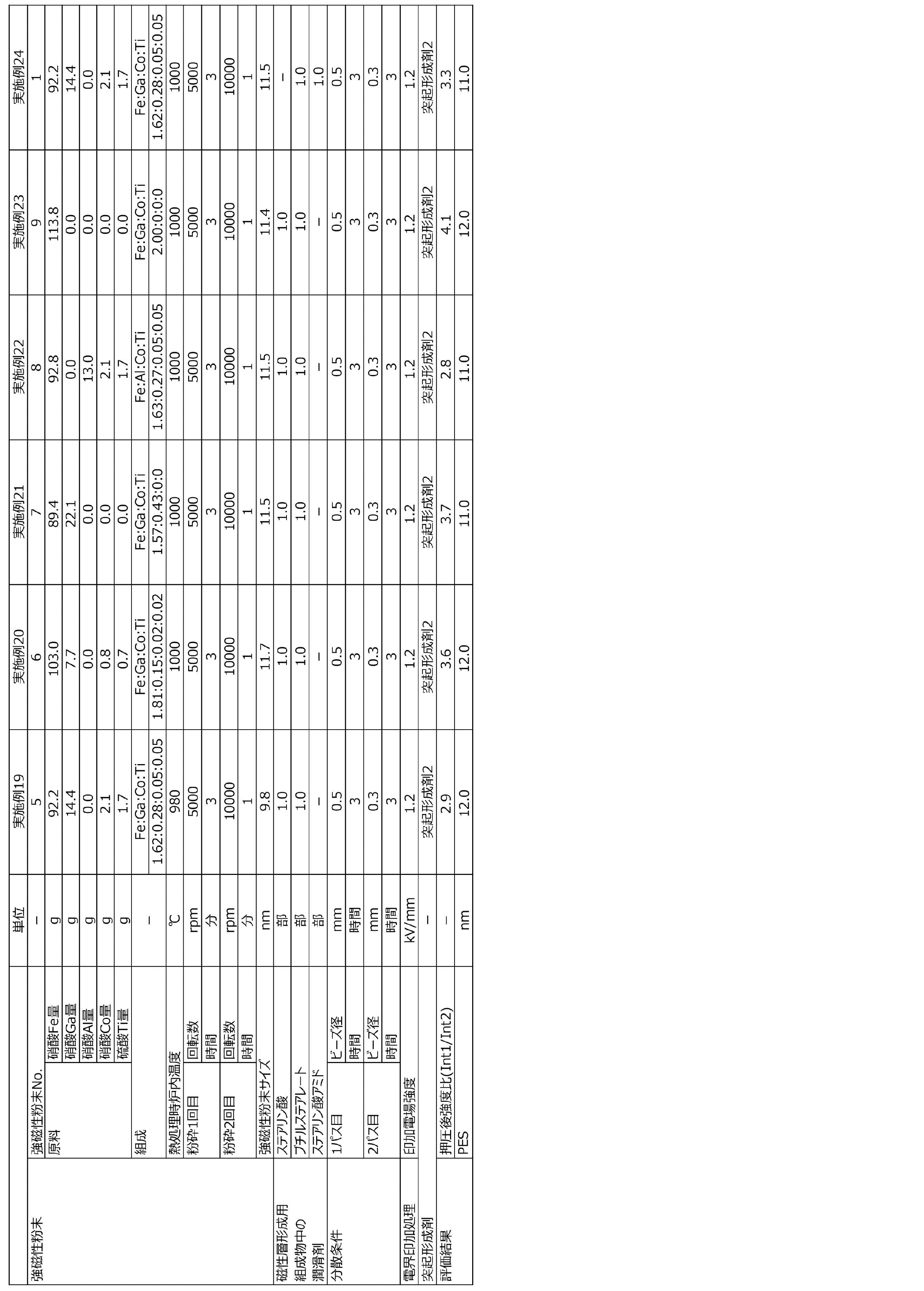


表1に示す結果から、実施例の磁気テープはいずれも、70atmの圧力での押圧後、即ち、長期保管後に相当する状態において、優れた走行安定性を示したことが確認できる。このような磁気テープであれば、アクセス頻度の低い情報が記録された後に長期保管された後に磁気記録再生装置内で安定走行可能であり、アーカイブ用記録媒体として好適である。
本発明の一態様は、データストレージ用途において有用である。
Claims (11)
- 非磁性支持体と、強磁性粉末を含む磁性層と、を有する磁気記録媒体であって、
前記強磁性粉末はε-酸化鉄粉末であり、
前記磁性層を70atmの圧力で押圧した後にIn-Plane法を用いた前記磁性層のX線回折分析により求められる回折強度の強度比、Int1/Int2、が1.0以上6.5以下であり、
前記Int1は、回折角2θχが29.0°以上31.0°以下の範囲における回折強度の最大値であり、
前記Int2は、回折角2θχが36.3°以上37.5°以下の範囲における回折強度の最大値である、磁気記録媒体。 - 前記強度比は1.5以上6.0以下である、請求項1に記載の磁気記録媒体。
- 前記強度比は3.0以上5.5以下である、請求項1または2に記載の磁気記録媒体。
- 前記ε-酸化鉄粉末はコバルト元素を含む、請求項1~3のいずれか1項に記載の磁気記録媒体。
- 前記ε-酸化鉄粉末は、ガリウム元素およびアルミニウム元素からなる群から選択される元素を更に含む、請求項4に記載の磁気記録媒体。
- 前記ε-酸化鉄粉末は、チタン元素を更に含む、請求項4または5に記載の磁気記録媒体。
- 前記非磁性支持体と前記磁性層との間に非磁性粉末を含む非磁性層を更に有する、請求項1~6のいずれか1項に記載の磁気記録媒体。
- 前記非磁性支持体の前記磁性層を有する表面側とは反対の表面側に非磁性粉末を含むバックコート層を更に有する、請求項1~7のいずれか1項に記載の磁気記録媒体。
- 磁気テープである、請求項1~8のいずれか1項に記載の磁気記録媒体。
- 請求項9に記載の磁気テープを含む磁気テープカートリッジ。
- 請求項1~9のいずれか1項に記載の磁気記録媒体を含む磁気記録再生装置。
Priority Applications (2)
| Application Number | Priority Date | Filing Date | Title |
|---|---|---|---|
| CN202280017178.XA CN116917989A (zh) | 2021-02-26 | 2022-02-24 | 磁记录介质、磁带盒及磁记录再生装置 |
| US18/455,273 US12159657B2 (en) | 2021-02-26 | 2023-08-24 | Magnetic recording medium having characterized magnetic layer, magnetic tape cartridge, and magnetic recording and reproducing device |
Applications Claiming Priority (2)
| Application Number | Priority Date | Filing Date | Title |
|---|---|---|---|
| JP2021-030919 | 2021-02-26 | ||
| JP2021030919A JP7558844B2 (ja) | 2021-02-26 | 2021-02-26 | 磁気記録媒体、磁気テープカートリッジおよび磁気記録再生装置 |
Related Child Applications (1)
| Application Number | Title | Priority Date | Filing Date |
|---|---|---|---|
| US18/455,273 Continuation US12159657B2 (en) | 2021-02-26 | 2023-08-24 | Magnetic recording medium having characterized magnetic layer, magnetic tape cartridge, and magnetic recording and reproducing device |
Publications (1)
| Publication Number | Publication Date |
|---|---|
| WO2022181704A1 true WO2022181704A1 (ja) | 2022-09-01 |
Family
ID=83049139
Family Applications (1)
| Application Number | Title | Priority Date | Filing Date |
|---|---|---|---|
| PCT/JP2022/007650 Ceased WO2022181704A1 (ja) | 2021-02-26 | 2022-02-24 | 磁気記録媒体、磁気テープカートリッジおよび磁気記録再生装置 |
Country Status (4)
| Country | Link |
|---|---|
| US (1) | US12159657B2 (ja) |
| JP (1) | JP7558844B2 (ja) |
| CN (1) | CN116917989A (ja) |
| WO (1) | WO2022181704A1 (ja) |
Families Citing this family (1)
| Publication number | Priority date | Publication date | Assignee | Title |
|---|---|---|---|---|
| US12537023B2 (en) * | 2023-09-11 | 2026-01-27 | Fujifilm Corporation | Magnetic tape, magnetic tape cartridge, and magnetic tape apparatus |
Citations (5)
| Publication number | Priority date | Publication date | Assignee | Title |
|---|---|---|---|---|
| JP2016130208A (ja) * | 2015-01-09 | 2016-07-21 | Dowaエレクトロニクス株式会社 | 鉄系酸化物磁性粒子粉およびその製造方法並びに塗料および磁気記録媒体 |
| WO2017094752A1 (ja) * | 2015-11-30 | 2017-06-08 | 国立大学法人 東京大学 | 配向体、その製造方法、その製造装置、及び磁気記録媒体 |
| JP2018110168A (ja) * | 2016-12-28 | 2018-07-12 | 国立研究開発法人産業技術総合研究所 | 磁性粒子およびその製造方法 |
| JP2020123419A (ja) * | 2019-01-31 | 2020-08-13 | 富士フイルム株式会社 | 磁気テープ、磁気テープカートリッジおよび磁気テープ装置 |
| JP2020140748A (ja) * | 2019-02-28 | 2020-09-03 | 富士フイルム株式会社 | 磁気記録媒体、イプシロン型酸化鉄粒子の製造方法、及び磁気記録媒体の製造方法 |
Family Cites Families (3)
| Publication number | Priority date | Publication date | Assignee | Title |
|---|---|---|---|---|
| US10854233B2 (en) * | 2017-09-29 | 2020-12-01 | Fujifilm Corporation | Magnetic recording medium having characterized magnetic layer and magnetic recording and reproducing device |
| WO2020166701A1 (ja) * | 2019-02-15 | 2020-08-20 | ソニー株式会社 | コバルトフェライト磁性粉およびその製造方法、ならびに磁気記録媒体 |
| JP6778803B1 (ja) * | 2019-09-17 | 2020-11-04 | 富士フイルム株式会社 | 磁気記録媒体および磁気記録再生装置 |
-
2021
- 2021-02-26 JP JP2021030919A patent/JP7558844B2/ja active Active
-
2022
- 2022-02-24 WO PCT/JP2022/007650 patent/WO2022181704A1/ja not_active Ceased
- 2022-02-24 CN CN202280017178.XA patent/CN116917989A/zh active Pending
-
2023
- 2023-08-24 US US18/455,273 patent/US12159657B2/en active Active
Patent Citations (5)
| Publication number | Priority date | Publication date | Assignee | Title |
|---|---|---|---|---|
| JP2016130208A (ja) * | 2015-01-09 | 2016-07-21 | Dowaエレクトロニクス株式会社 | 鉄系酸化物磁性粒子粉およびその製造方法並びに塗料および磁気記録媒体 |
| WO2017094752A1 (ja) * | 2015-11-30 | 2017-06-08 | 国立大学法人 東京大学 | 配向体、その製造方法、その製造装置、及び磁気記録媒体 |
| JP2018110168A (ja) * | 2016-12-28 | 2018-07-12 | 国立研究開発法人産業技術総合研究所 | 磁性粒子およびその製造方法 |
| JP2020123419A (ja) * | 2019-01-31 | 2020-08-13 | 富士フイルム株式会社 | 磁気テープ、磁気テープカートリッジおよび磁気テープ装置 |
| JP2020140748A (ja) * | 2019-02-28 | 2020-09-03 | 富士フイルム株式会社 | 磁気記録媒体、イプシロン型酸化鉄粒子の製造方法、及び磁気記録媒体の製造方法 |
Also Published As
| Publication number | Publication date |
|---|---|
| JP2022131787A (ja) | 2022-09-07 |
| US20230402060A1 (en) | 2023-12-14 |
| CN116917989A (zh) | 2023-10-20 |
| JP7558844B2 (ja) | 2024-10-01 |
| US12159657B2 (en) | 2024-12-03 |
Similar Documents
| Publication | Publication Date | Title |
|---|---|---|
| JP7105211B2 (ja) | 磁気テープ、磁気テープカートリッジおよび磁気記録再生装置 | |
| JP7441963B2 (ja) | 磁気記録媒体、磁気テープカートリッジおよび磁気記録再生装置 | |
| JP7277408B2 (ja) | 磁気記録媒体、磁気テープカートリッジおよび磁気記録再生装置 | |
| JP7236493B2 (ja) | 磁気テープおよび磁気記録再生装置 | |
| JP2023073302A (ja) | 磁気テープ、磁気テープカートリッジおよび磁気テープ装置 | |
| JP7685410B2 (ja) | 磁気記録媒体、磁気テープカートリッジおよび磁気記録再生装置 | |
| JP2021144778A (ja) | 磁気記録媒体、磁気テープカートリッジおよび磁気記録再生装置 | |
| JP7303770B2 (ja) | 磁気テープ、磁気テープカートリッジおよび磁気記録再生装置 | |
| JP2023049196A (ja) | 磁気記録媒体、磁気テープカートリッジおよび磁気記録再生装置 | |
| US12159657B2 (en) | Magnetic recording medium having characterized magnetic layer, magnetic tape cartridge, and magnetic recording and reproducing device | |
| JP7580300B2 (ja) | 磁気記録媒体、磁気テープカートリッジおよび磁気記録再生装置 | |
| JP7303769B2 (ja) | 磁気テープ、磁気テープカートリッジおよび磁気記録再生装置 | |
| US20230290376A1 (en) | Magnetic recording medium, magnetic tape cartridge, and magnetic recording and reproducing device | |
| JP2023133920A (ja) | 磁気記録媒体、磁気テープカートリッジおよび磁気記録再生装置 | |
| JP7106481B2 (ja) | 磁気記録媒体および磁気記録再生装置 | |
| JP2021144775A (ja) | 磁気記録媒体、磁気テープカートリッジおよび磁気記録再生装置 | |
| JP7271466B2 (ja) | 磁気記録媒体、磁気テープカートリッジおよび磁気記録再生装置 | |
| JP7232207B2 (ja) | 磁気記録媒体、磁気テープカートリッジおよび磁気記録再生装置 | |
| JP7406647B2 (ja) | 磁気記録媒体、磁気テープカートリッジおよび磁気記録再生装置 | |
| JP7406648B2 (ja) | 磁気記録媒体、磁気テープカートリッジおよび磁気記録再生装置 | |
| JP7303768B2 (ja) | 磁気テープ、磁気テープカートリッジおよび磁気記録再生装置 | |
| JP7441964B2 (ja) | 磁気記録媒体、磁気テープカートリッジおよび磁気記録再生装置 | |
| JP7249969B2 (ja) | 磁気テープ、磁気テープカートリッジおよび磁気記録再生装置 | |
| JP7432785B2 (ja) | 磁気記録媒体および磁気記録再生装置 | |
| JP7299205B2 (ja) | 磁気記録媒体および磁気記録再生装置 |
Legal Events
| Date | Code | Title | Description |
|---|---|---|---|
| 121 | Ep: the epo has been informed by wipo that ep was designated in this application |
Ref document number: 22759739 Country of ref document: EP Kind code of ref document: A1 |
|
| WWE | Wipo information: entry into national phase |
Ref document number: 202280017178.X Country of ref document: CN |
|
| NENP | Non-entry into the national phase |
Ref country code: DE |
|
| 122 | Ep: pct application non-entry in european phase |
Ref document number: 22759739 Country of ref document: EP Kind code of ref document: A1 |