WO2022181031A1 - Work machine - Google Patents
Work machine Download PDFInfo
- Publication number
- WO2022181031A1 WO2022181031A1 PCT/JP2021/048088 JP2021048088W WO2022181031A1 WO 2022181031 A1 WO2022181031 A1 WO 2022181031A1 JP 2021048088 W JP2021048088 W JP 2021048088W WO 2022181031 A1 WO2022181031 A1 WO 2022181031A1
- Authority
- WO
- WIPO (PCT)
- Prior art keywords
- filter member
- filter
- cyclone
- air
- inlet
- Prior art date
Links
- 238000011144 upstream manufacturing Methods 0.000 claims abstract description 6
- 230000002093 peripheral effect Effects 0.000 claims description 25
- 230000035699 permeability Effects 0.000 claims description 4
- 239000004745 nonwoven fabric Substances 0.000 claims description 2
- 239000000428 dust Substances 0.000 description 52
- 229910052602 gypsum Inorganic materials 0.000 description 5
- 239000010440 gypsum Substances 0.000 description 5
- 238000012423 maintenance Methods 0.000 description 4
- 239000011148 porous material Substances 0.000 description 4
- 230000004308 accommodation Effects 0.000 description 3
- 230000004048 modification Effects 0.000 description 3
- 238000012986 modification Methods 0.000 description 3
- 239000002245 particle Substances 0.000 description 3
- 239000011347 resin Substances 0.000 description 3
- 229920005989 resin Polymers 0.000 description 3
- XLYOFNOQVPJJNP-UHFFFAOYSA-N water Substances O XLYOFNOQVPJJNP-UHFFFAOYSA-N 0.000 description 2
- 230000015572 biosynthetic process Effects 0.000 description 1
- 230000000903 blocking effect Effects 0.000 description 1
- 230000000694 effects Effects 0.000 description 1
- 238000001914 filtration Methods 0.000 description 1
- 229920002635 polyurethane Polymers 0.000 description 1
- 239000004814 polyurethane Substances 0.000 description 1
Images


Classifications
-
- A—HUMAN NECESSITIES
- A47—FURNITURE; DOMESTIC ARTICLES OR APPLIANCES; COFFEE MILLS; SPICE MILLS; SUCTION CLEANERS IN GENERAL
- A47L—DOMESTIC WASHING OR CLEANING; SUCTION CLEANERS IN GENERAL
- A47L9/00—Details or accessories of suction cleaners, e.g. mechanical means for controlling the suction or for effecting pulsating action; Storing devices specially adapted to suction cleaners or parts thereof; Carrying-vehicles specially adapted for suction cleaners
- A47L9/10—Filters; Dust separators; Dust removal; Automatic exchange of filters
- A47L9/16—Arrangement or disposition of cyclones or other devices with centrifugal action
Definitions
- the present invention relates to a working machine such as a cleaner.
- a cleaner provided with a cyclone unit for centrifugally separating and collecting dust from air containing dust is known as an example of a working machine.
- a filter member for filtering the air that has passed through the cyclone unit is provided in front of the motor and the fan in order to prevent dust that has passed through the cyclone unit from entering the motor.
- Japanese Patent Laid-Open No. 2002-100001 describes a cleaner having a filter member positioned upstream of a motor or a fan.
- gypsum dust has a relatively large particle size and When dust that easily sticks is sucked, the filter member may quickly become clogged. As a result, the suction force is reduced early, and the maintenance frequency of the filter member is increased, resulting in poor workability of the cleaner.
- An object of the present invention is to provide a working machine with improved workability.
- a work machine includes a fan accommodating section that accommodates a fan rotated by a motor, a first cyclone section in which an air flow sucked by the rotation of the fan circulates, and A second cyclone section in which the air flow discharged from the first cyclone section swirls; and a filter housing section that connects the second cyclone section and the fan housing section and houses a filter section therein.
- the filter unit comprises a first filter member arranged to block an air flow path from the inflow port to the outflow port, and arranged upstream of the flow channel from the first filter member, and a second filter member having higher air permeability than the first filter member, and a space is formed between the second filter member and the inlet.
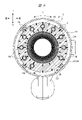
- FIG. 2 is a vertical cross-sectional view of the cleaner shown in FIG. 1 ; 2 is an enlarged partial cross-sectional view showing airflow in the cleaner shown in FIG. 1; FIG. FIG. 2 is a cross-sectional view taken along line AA shown in FIG. 1; FIG. 2 is a cross-sectional view taken along line BB shown in FIG. 1; FIG. 2 is a cross-sectional view taken along line CC shown in FIG. 1; FIG. 2 is a perspective view showing a structure of the cleaner shown in FIG.
- FIG. 2 is a cross-sectional view of the cleaner of the first modified example of the present invention taken along line CC of FIG. 1;
- FIG. 9 is a perspective view showing a state where the second filter member of the cleaner shown in FIG. 8 is attached to the first filter member;
- FIG. 11 is an enlarged partial cross-sectional view showing the airflow in the cleaner of the second modified example of the present invention;
- the cleaner 1 will be described as an example of the working machine.
- An example of a cleaner 1 is shown in FIGS. 1-7.
- the same or equivalent elements shown in each figure are given the same reference numerals.
- the body portion 2 includes a housing 6 that accommodates the fan motor 10 shown in FIG. 2 and a grip portion 4 for handling connected to the housing 6 .
- the fan motor 10 is a motor having a rotating shaft to which a fan is attached, and is provided in a fan accommodating portion 30 inside the housing 6 .
- a battery 5 is detachably attached to the holding portion of the housing 6 as a battery for supplying electric power to the fan motor 10 .
- a plurality of body exhaust ports 20 are formed in the housing 6 in the vicinity of the holding portion of the battery 5 to exhaust the sucked air.
- the grip portion 4 is provided with an operation portion 9 in which a switch for turning ON/OFF the power of the cleaner 1 is arranged.
- the cleaner 1 also includes a dust collecting portion 3 attached to the housing 6 and a dust accommodating member 7 attached to the dust collecting portion 3 and capable of accommodating dust sucked in together with air. Further, inside the dust collecting section 3, a first cyclone section 28 shown in FIG. A plurality of second cyclone units 29 are provided for separating unseparated dust from the air by centrifugal force. In addition, as shown in FIG. 4 , a plurality of second cyclone portions 29 are provided along the circumferential direction R outside the first cyclone portion 28 . In the first cyclone section 28, an air flow, which is a flow of air sucked by the rotation of the fan, swirls inside. On the other hand, in the second cyclone section 29, the air flow that has flowed out from the first cyclone section 28 swirls inside. That is, the cleaner 1 of the present embodiment is a two-stage cyclone working machine.
- the fan motor 10 rotates, and the rotation of the fan motor 10 causes air and dust to pass through the dust collection unit intake port 8 formed near the tip of the cleaner 1. inhale. Then, the sucked air and dust are swirled in the tubular first cyclone portion 28 and separated by centrifugal force. Further, the air enters the plurality of tubular second cyclone portions 29, and is swirled in each of the plurality of second cyclone portions 29, so that the dust that has not been completely separated in the first cyclone portion 28 is removed from the air by centrifugal force. To separate. After that, the air passes through the inside of the housing 6 and is exhausted to the outside from the plurality of body exhaust ports 20 .
- the first cyclone exhaust port 12 which is the exhaust port of the first cyclone section 28 shown in FIG.
- An air flow path is formed so that and communicate with each other. Furthermore, as shown in FIG. 2, the air flow is made so that the second cyclone outlet 16, which is the outlet of the second cyclone section 29, and the fan motor inlet 21, which is the inlet of the fan motor 10, communicate with each other. A path is formed.
- the cleaner 1 of the present embodiment includes a filter housing chamber (filter housing portion) 22 to which the fan motor intake port 21 and the second cyclone exhaust port 16 serving as the exhaust port of the second cyclone portion 29 are connected.
- the filter accommodation chamber 22 is provided between the second cyclone portion 29 and the fan accommodation portion 30 .
- the second cyclone portion 29 and the fan accommodating portion 30 are connected to each other, and the filter accommodating chamber 22 for accommodating the filter portion 31 shown in FIG. 3 is provided inside.
- a first filter member 18 and a second filter member 19 arranged so as to cover the outer peripheral portion of the first filter member 18 are provided in the filter portion 31 inside the filter housing chamber 22 .
- the second filter member 19 is arranged on the upstream side of the air flow path from the first filter member 18 .
- the fan motor 10 rotates to suck in air and dust through the dust collecting section intake port 8 formed near the tip of the cleaner 1.
- the sucked air and dust become an air flow P1 and enter the first cyclone section 28 as shown in FIGS.
- a cylindrical mesh filter 13 is provided in the first cyclone section 28 along an axis (center line) Q, and an airflow P2 containing dust revolves around the mesh filter 13 . Air and dust are separated by the centrifugal force generated when the airflow P2 swirls, and the separated dust is stored in the first cyclone dust collection chamber 14 .
- the air flow P3 that has passed through the mesh filter 13 advances as an air flow P4 through the first cyclone exhaust port 12 as shown in FIG. It enters each of the plurality of second cyclone portions 29 through the port 15 .
- each of the plurality of second cyclone portions 29 turns into an air flow P5 and swirls.
- a centrifugal force is generated by turning the air flow P5 in each of the second cyclone portions 29, and the dust that has not been separated by the first cyclone portion 28 is separated from the air by this centrifugal force.
- the dust separated by the second cyclone section 29 is stored in the second cyclone dust collection chamber 17 shown in FIG. After that, the air becomes an air flow P6 and enters the filter section 31 inside the filter housing chamber 22 via the second cyclone exhaust port (inflow port) 16 .
- the air entering the inside of the filter housing chamber 22 passes through the second filter member 19 as an air flow P7 and then passes through the first filter member 18 as an air flow P8. After passing through the first filter member 18 , the air becomes an air flow P 9 and enters the fan accommodating portion 30 in the housing 6 via the fan motor inlet (outlet) 21 .
- the air that has entered the fan accommodating portion 30 becomes an air flow P10, passes through the fan motor 10, and is then exhausted to the outside of the cleaner 1 through the plurality of main body exhaust ports 20 shown in FIG.
- the filter housing chamber 22 which is the filter housing portion, opens in the first direction (opening direction) X, and has an outlet (outlet) through which the air flow flows out toward the fan housing portion 30. 21 and a plurality of inlets (second cyclone outlets) 16 into which the air flows from the second cyclone section 29 .
- the first direction X is the front-rear direction of the cleaner 1 shown in FIG. That is, both the outflow port 21 and the inflow port 16 are opened along the axis Q. As shown in FIG.
- a first filter member 18 is disposed so as to block the flow path of the air flow from the inlet 16 to the outlet 21 , and the flow path is larger than the first filter member 18 .
- a second filter member 19 arranged upstream of the first filter member 18 and having higher air permeability than the first filter member 18 .
- the second filter member 19 is coarser than the first filter member 18 .
- the pore diameters of the plurality of pores provided in the second filter member 19 are larger than the pore diameters of the plurality of pores provided in the first filter member 18 .
- the second filter member 19 is formed so that the dust particle collection efficiency of the second filter member 19 is lower than the dust particle collection efficiency of the first filter member 18 .
- the first filter member 18 is formed in a tubular shape centered on an axis Q extending in the first direction X shown in FIG. Furthermore, the first filter member 18 also communicates with the inflow port (second cyclone exhaust port) 16 .
- the second filter member 19 is also formed in a tubular shape centered on the axis Q. As shown in FIG. That is, as shown in FIG. 7, both the first filter member 18 and the second filter member 19 are formed in a tubular shape.
- the first filter member 18 is, for example, a HEPA filter made of nonwoven fabric
- the second filter member 19 is made of, for example, sponge.
- a sponge consists of resin, such as a polyurethane, as an example.
- a (space) 25 is formed in the filter housing chamber 22 shown in FIG.
- the cylindrical second filter member 19 has a first air intake surface 23 on the side of its outer peripheral surface facing the second cyclone exhaust port (inlet) 16 .
- a first gap 25 is formed between 23 and the second cyclone outlet 16 . In other words, the formation of the first gap 25 prevents the second filter member 19 from blocking the second cyclone exhaust port (inflow port) 16 .
- the first gap 25 is formed between the first air intake surface 23 on the outer peripheral surface of the second filter member 19 and the second cyclone exhaust port 16 in this way, the air containing dust is allowed to pass through this first space. It can enter the second filter member 19 through the gap 25 . As a result, dust can be collected by the second filter member 19 before the dust reaches the first filter member 18, and clogging of the first filter member 18 can be suppressed. Also, in the second filter member 19 , the first gap 25 allows the airflow to pass over a wide area of the first intake surface 23 . As a result, the dust contained in the airflow can be collected by the large surface area of the second filter member 19, and the total amount of dust that can be collected by the second filter member 19 can be increased.
- a plurality of inlets (second cyclone exhaust ports) 16 are provided in the outer peripheral portion of the second filter member 19 in the radial direction Y about the axis Q in the filter housing chamber 22.
- a second gap (space) 26 communicating with the plurality of inlets (second cyclone exhaust ports) 16 is formed.
- the second air intake surface 24 is provided on the outer peripheral surface of the second filter member 19 shown in FIG.
- a second gap 26 is formed between 24 and the wall surface 27 of the filter housing chamber, which is the inner wall surface of the filter portion 31 .
- the first gap 25 and the second gap 26 communicate with each other at the outer peripheral portion of the second filter member 19 .
- the outer peripheral portion of the second filter member 19 has a wide exposed portion consisting of the first air intake surface 23 and the second air intake surface 24 shown in FIG. That is, the outer peripheral portion of the second filter member 19 has a large surface area that is exposed without being blocked.
- the second gap 26 since the second gap 26 is provided, it is possible to secure a gap for the air to flow toward the second air intake surface 24 side, and the second filter member in a state in which the air flows toward the second air intake surface 24 side. 19 can be entered. As a result, dust contained in the airflow can be collected over a wider surface area by utilizing the second air intake surface 24, and as a result, the total amount of dust that can be collected by the second filter member 19 can be increased. can be done.
- the outer peripheral portion of the second filter member 19 since the outer peripheral surface of the second filter member 19 is provided with the second suction surface 24, the outer peripheral portion of the second filter member 19 has a large volume portion that is exposed without being blocked. As a result, a large amount of dust can adhere to the large-volume portion of the second filter member 19, and the total amount of dust that can be collected by the second filter member 19 can be further increased.
- a plurality of inlets (second cyclone exhaust ports) 16 are arranged side by side in the circumferential direction R centering on the axis Q, and a cylindrical second filter member 19 is provided. are provided so as to overlap with the plurality of inlets (second cyclone exhaust ports) 16 in the radial direction Y about the axis Q. As shown in FIG.
- the air discharged from each of the plurality of inlets (second cyclone outlets) 16 can pass through the second filter member 19 as it is, and dust contained in the air can be easily collected. .
- the second filter member 19 is detachably attached to the outer peripheral portion of the first filter member 18 .
- the first filter member 18 has a disk-shaped resin wall portion 18a disposed on the second cyclone portion 29 side. is formed with a flange portion 18b.
- the second filter member 19 is detachably fitted to the flange portion 18b. Therefore, the second filter member 19 can be easily and independently removed from the first filter member 18 by deforming the second filter member 19 to release the fitting to the flange portion 18b. That is, when performing maintenance on the second filter member 19, only the first filter member 18 and the second filter member 19 can be removed for maintenance.
- the second filter member 19 when the second filter member 19 is made of sponge, only the second filter member 19 can be removed and washed with water easily. Even when a large amount of dust generated from the gypsum board adheres to the second filter member 19, only the second filter member 19 can be removed and washed with water, improving the workability of the cleaner 1. can be planned.
- the first filter member 18 has a disk-shaped resin wall portion 18a disposed on the second cyclone portion 29 side.
- the disk-shaped wall portion 18a can prevent the air containing dust that has flowed into the first gap 25 from flowing toward the central portion inside the filter housing chamber 22 . That is, it is possible to prevent the dust-containing air that has flowed into the first gap 25 from directly entering the first filter member 18 without passing through the second filter member 19 . As a result, it is possible to reduce the adhesion of dust from the gypsum board or the like to the first filter member 18 .
- a first modification shown in FIGS. 8 and 9 is obtained by changing the shape of the outer peripheral portion of the second filter member 19 with respect to the cleaner 1 shown in FIG.
- a tubular second filter member 19 is attached to the outer peripheral portion of the tubular first filter member 18, and the second filter member 19 has unevenness on the outer peripheral portion. is formed.
- a concave portion 19 a and a convex portion 19 b are formed on the outer peripheral portion of the second filter member 19 .
- the upper surface of the convex portion 19b forms an outer peripheral portion so as to contact the wall surface 27 of the filter housing chamber, and has a shape in which the surface area and volume of the outer peripheral portion of the second filter member 19 are increased. be. It is also possible to employ the second filter member 19 having such a shape that unevenness is formed on the outer peripheral portion.
- a second modification shown in FIG. 10 is a filter in which the first filter member 18 is folded. It is intended to enter from the direction along Q. Therefore, since it is necessary for the air to pass through the second filter member 19 before passing through the first filter member 18, the second filter member 19 is composed of a ring-shaped filter outer peripheral portion 19c and an integral portion of the filter outer peripheral portion 19c. and a disk-shaped filter central portion 19d formed in the center portion 19d. As a result, the disk-shaped filter center portion 19d of the second filter member 19 covers the second cyclone portion 29 side of the first filter member 18. As shown in FIG.
- part of the dust-containing air that has flowed into the first gap 25 enters the center-directed flow path 22a formed inside the filter housing chamber 22 and forms an air flow P11 toward the center of the main body. After flowing, it passes through the disk-shaped filter center portion 19 d of the second filter member 19 and then through the first filter member 18 . The other part of the dust-containing air that has flowed into the first gap 25 passes through the filter outer peripheral portion 19 c of the second filter member 19 and then through the first filter member 18 .
- the cleaner 1 of the second modified example shown in FIG. 10 can also obtain the same effect as the cleaner 1 shown in FIG.
- a plurality of inlets (second cyclone exhaust ports) 16 are formed in the second cyclone section 29 , and each of these plurality of inlets (second cyclone exhaust ports) 16 is connected to the filter housing chamber 22 .
- I have described a structure that communicates with the .
- a structure may be adopted in which each of the plurality of second cyclone exhaust ports 16 communicates with one channel, and this one channel communicates with the filter housing chamber 22 .
- both the outflow port 21 and the inflow port 16 are opened along the axis Q, but the opening directions are not limited to this and may be different from each other.
- both the first filter member 18 and the second filter member 19 are formed in a cylindrical shape centered on the axis Q, the axial directions of the cylinders are not limited to this, and may be different from each other.
- the outflow port 21 opens along the axis Q
- the first filter member 18 and the second filter member 19 are formed in a cylindrical shape centered on the axis Q
- the inflow port 16 is perpendicular to the axis Q.
- a configuration in which the inlet is opened along the axis that is, a configuration in which the opening direction of the inlet is different from the axis Q may be employed.
- the first gap 25 is formed between the second filter member 19 and the inlet 16 at least in the opening direction of the inlet 16, that is, in the direction of the axis perpendicular to the axis Q.
- the object of the present invention can be achieved by forming a space between the second filter member 19 and the inlet 16. Therefore, either one of the first gap 25 and the second gap 26 may be provided, or neither of them may be provided.
- the inlet 16 is formed on the outer circumference side of the outer circumference of the second filter member 19, a space is formed without providing the first gap 25, so the object of the present invention is achieved.
Abstract
In order to enhance working efficiency in a work machine, the present invention has a fan accommodating part 30 for accommodating a fan motor 10, a first cyclone part 28 through the inside of which indrawn air circles, a second cyclone part 29 through the inside of which air flowing out from the first cyclone part 28 circles, and a filter accommodating space 22 in which a filter member is provided. The filter accommodating chamber 22 is provided with a fan motor intake port 21, a second cyclone exhaust port 16, a first filter member 18 disposed so as to block an air flow channel from the second cyclone exhaust port 16 to the fan motor intake port 21, and a second filter member 19 disposed further upstream than the first filter member 18. A space is formed between the second filter member 19 and the second cyclone exhaust port 16.
Description
本発明は、クリーナなどの作業機に関する。
The present invention relates to a working machine such as a cleaner.
作業機の一例として、粉塵混じりの空気から粉塵を遠心分離して捕集するサイクロンユニットが設けられたクリーナが知られている。このようなクリーナにおいては、サイクロンユニットを通過した粉塵がモータ側へ進入することを抑制するため、サイクロンユニットを通過した空気を濾過するフィルタ部材がモータやファンの前段の位置に設けられる。
A cleaner provided with a cyclone unit for centrifugally separating and collecting dust from air containing dust is known as an example of a working machine. In such a cleaner, a filter member for filtering the air that has passed through the cyclone unit is provided in front of the motor and the fan in order to prevent dust that has passed through the cyclone unit from entering the motor.
このようにモータやファンの前段の位置にフィルタ部材を備えたクリーナが特許文献1に記載されている。
Japanese Patent Laid-Open No. 2002-100001 describes a cleaner having a filter member positioned upstream of a motor or a fan.
上記特許文献1に記載されたクリーナのように、モータやファンの前段の位置のみにフィルタ部材が設けられた構造では、例えば、石膏の粉塵のように、粒径が比較的大きく、かつ、互いに張り付きやすい塵埃を吸引した場合、フィルタ部材が早期に目詰まりを起こすことがある。その結果、吸引力が早期に低下するとともにフィルタ部材のメンテナンス頻度も多くなり、クリーナの作業性が悪かった。
Like the cleaner described in Patent Document 1, in a structure in which a filter member is provided only at a position in front of a motor or a fan, for example, gypsum dust has a relatively large particle size and When dust that easily sticks is sucked, the filter member may quickly become clogged. As a result, the suction force is reduced early, and the maintenance frequency of the filter member is increased, resulting in poor workability of the cleaner.
本発明の目的は、作業性の向上が図られた作業機を提供することにある。
SUMMARY OF THE INVENTION An object of the present invention is to provide a working machine with improved workability.
一実施の形態の作業機は、モータによって回転されるファンを収容するファン収容部と、前記ファンの回転によって吸引される空気の流れである空気流が内部を旋回する第1サイクロン部と、前記第1サイクロン部から流出した前記空気流が内部を旋回する第2サイクロン部と、前記第2サイクロン部と前記ファン収容部とを接続し、内部にフィルタ部を収容するフィルタ収容部と、を有し、前記フィルタ収容部は、軸線に沿った方向に開口し、前記ファン収容部へ空気が流出される流出口と、前記第2サイクロン部から空気が流入される流入口と、を有し、前記フィルタ部は、前記流入口から前記流出口へ向かう空気の流路を塞ぐように配置される第1フィルタ部材と、前記第1フィルタ部材よりも前記流路の上流側に配置され、かつ、前記第1フィルタ部材よりも通気性が高い第2フィルタ部材と、を備え、前記第2フィルタ部材と前記流入口との間に空間が形成されている。
A work machine according to one embodiment includes a fan accommodating section that accommodates a fan rotated by a motor, a first cyclone section in which an air flow sucked by the rotation of the fan circulates, and A second cyclone section in which the air flow discharged from the first cyclone section swirls; and a filter housing section that connects the second cyclone section and the fan housing section and houses a filter section therein. and the filter accommodating portion has an outlet opening in a direction along the axis, through which air flows out to the fan accommodating portion, and an inlet through which air flows in from the second cyclone portion, The filter unit comprises a first filter member arranged to block an air flow path from the inflow port to the outflow port, and arranged upstream of the flow channel from the first filter member, and a second filter member having higher air permeability than the first filter member, and a space is formed between the second filter member and the inlet.
本発明によれば、作業機における作業性の向上を図ることができる。
ADVANTAGE OF THE INVENTION According to this invention, the improvement of the workability|operativity in a working machine can be aimed at.
本実施の形態の作業機について図面を参照して説明する。
A work machine according to the present embodiment will be described with reference to the drawings.
本実施の形態では、作業機の一例として、クリーナ1を取り上げて説明する。クリーナ1の一例が、図1~図7に示されている。なお、各図に示される同一の要素、または同等の要素には、それぞれ同一の符号を付してある。
In this embodiment, the cleaner 1 will be described as an example of the working machine. An example of a cleaner 1 is shown in FIGS. 1-7. The same or equivalent elements shown in each figure are given the same reference numerals.
図1に示す本実施の形態のクリーナ1は、本体部2を備えている。そして、本体部2は、図2に示すファンモータ10を収容するハウジング6と、ハウジング6に接続されたハンドリング用の把持部4と、を備えている。ファンモータ10は、ファンが取り付けられた回転軸を有するモータであり、ハウジング6内のファン収容部30に設けられている。また、ハウジング6の保持部には、ファンモータ10に電力を供給するバッテリとして電池5が着脱自在に取り付けられている。そして、ハウジング6における電池5の保持部の近傍には、吸い込んだ空気を排気させるための複数の本体排気口20が形成されている。さらに、把持部4には、クリーナ1の電源をON/OFFするスイッチ等が配置された操作部9が設けられている。
The cleaner 1 of this embodiment shown in FIG. The body portion 2 includes a housing 6 that accommodates the fan motor 10 shown in FIG. 2 and a grip portion 4 for handling connected to the housing 6 . The fan motor 10 is a motor having a rotating shaft to which a fan is attached, and is provided in a fan accommodating portion 30 inside the housing 6 . A battery 5 is detachably attached to the holding portion of the housing 6 as a battery for supplying electric power to the fan motor 10 . A plurality of body exhaust ports 20 are formed in the housing 6 in the vicinity of the holding portion of the battery 5 to exhaust the sucked air. Further, the grip portion 4 is provided with an operation portion 9 in which a switch for turning ON/OFF the power of the cleaner 1 is arranged.
また、クリーナ1は、ハウジング6に取り付けられる集じん部3と、集じん部3に取り付けられ、空気とともに吸い込んだ塵埃を収容可能な塵埃収容部材7と、を備えている。さらに、集じん部3の内部には、吸い込んだ空気と塵埃を遠心力で分離する図3に示す第1サイクロン部28と、第1サイクロン部28の周囲に配置され、第1サイクロン部28で分離しきれなかった塵埃を遠心力で空気から分離する複数の第2サイクロン部29と、が設けられている。なお、図4に示すように、第2サイクロン部29は、第1サイクロン部28の外側において周方向Rに沿って複数設けられている。そして、第1サイクロン部28では、その内部において、上記ファンの回転によって吸引された空気の流れである空気流が旋回する。一方、第2サイクロン部29では、第1サイクロン部28から流出した空気流が内部において旋回する。すなわち、本実施の形態のクリーナ1は、2段サイクロン式の作業機である。
The cleaner 1 also includes a dust collecting portion 3 attached to the housing 6 and a dust accommodating member 7 attached to the dust collecting portion 3 and capable of accommodating dust sucked in together with air. Further, inside the dust collecting section 3, a first cyclone section 28 shown in FIG. A plurality of second cyclone units 29 are provided for separating unseparated dust from the air by centrifugal force. In addition, as shown in FIG. 4 , a plurality of second cyclone portions 29 are provided along the circumferential direction R outside the first cyclone portion 28 . In the first cyclone section 28, an air flow, which is a flow of air sucked by the rotation of the fan, swirls inside. On the other hand, in the second cyclone section 29, the air flow that has flowed out from the first cyclone section 28 swirls inside. That is, the cleaner 1 of the present embodiment is a two-stage cyclone working machine.
したがって、作業者が操作部9のスイッチをON状態にすると、ファンモータ10が回転し、ファンモータ10の回転によってクリーナ1の先端付近に形成された集じん部吸気口8を介して空気と塵埃を吸い込む。そして、吸い込まれた空気と塵埃は、筒状の第1サイクロン部28で旋回して遠心力により空気と塵埃とが分離される。さらに、空気はそれぞれ筒状の複数の第2サイクロン部29に進入し、複数の第2サイクロン部29のそれぞれで旋回して第1サイクロン部28で分離しきれなかった塵埃を遠心力で空気から分離する。その後、空気は、ハウジング6内を通って複数の本体排気口20から外部に排気される。
Therefore, when the operator turns on the switch of the operation unit 9, the fan motor 10 rotates, and the rotation of the fan motor 10 causes air and dust to pass through the dust collection unit intake port 8 formed near the tip of the cleaner 1. inhale. Then, the sucked air and dust are swirled in the tubular first cyclone portion 28 and separated by centrifugal force. Further, the air enters the plurality of tubular second cyclone portions 29, and is swirled in each of the plurality of second cyclone portions 29, so that the dust that has not been completely separated in the first cyclone portion 28 is removed from the air by centrifugal force. To separate. After that, the air passes through the inside of the housing 6 and is exhausted to the outside from the plurality of body exhaust ports 20 .
なお、クリーナ1では、図2に示す第1サイクロン部28の排気口である第1サイクロン排気口12と、図5に示す第2サイクロン部29の吸気口である複数の第2サイクロン吸気口15と、が連通するように空気の流路が形成される。さらに、図2に示すように、第2サイクロン部29の排気口である第2サイクロン排気口16と、ファンモータ10の吸気口となるファンモータ吸気口21と、が連通するように空気の流路が形成される。
In the cleaner 1, the first cyclone exhaust port 12, which is the exhaust port of the first cyclone section 28 shown in FIG. An air flow path is formed so that and communicate with each other. Furthermore, as shown in FIG. 2, the air flow is made so that the second cyclone outlet 16, which is the outlet of the second cyclone section 29, and the fan motor inlet 21, which is the inlet of the fan motor 10, communicate with each other. A path is formed.
また、本実施の形態のクリーナ1は、ファンモータ吸気口21と、第2サイクロン部29の排気口となる第2サイクロン排気口16と、が接続されるフィルタ収容室(フィルタ収容部)22を有している。言い換えると、第2サイクロン部29とファン収容部30との間にフィルタ収容室22が設けられている。具体的には、第2サイクロン部29とファン収容部30とを接続し、内部に図3に示すフィルタ部31を収容するフィルタ収容室22を備えている。
In addition, the cleaner 1 of the present embodiment includes a filter housing chamber (filter housing portion) 22 to which the fan motor intake port 21 and the second cyclone exhaust port 16 serving as the exhaust port of the second cyclone portion 29 are connected. have. In other words, the filter accommodation chamber 22 is provided between the second cyclone portion 29 and the fan accommodation portion 30 . Specifically, the second cyclone portion 29 and the fan accommodating portion 30 are connected to each other, and the filter accommodating chamber 22 for accommodating the filter portion 31 shown in FIG. 3 is provided inside.
そして、このフィルタ収容室22内部のフィルタ部31に、第1フィルタ部材18と、第1フィルタ部材18の外周部を覆うように配置された第2フィルタ部材19と、が設けられている。具体的には、第2フィルタ部材19は、第1フィルタ部材18より空気の流路の上流側に配置されている。
A first filter member 18 and a second filter member 19 arranged so as to cover the outer peripheral portion of the first filter member 18 are provided in the filter portion 31 inside the filter housing chamber 22 . Specifically, the second filter member 19 is arranged on the upstream side of the air flow path from the first filter member 18 .
クリーナ1では、図2に示すように、ファンモータ10の回転によってクリーナ1の先端付近に形成された集じん部吸気口8を介して空気と塵埃を吸い込む。そして、吸い込まれた空気と塵埃は空気流P1となって図3および図4に示すように第1サイクロン部28に進入する。第1サイクロン部28には、軸線(中心線)Qに沿って円筒状のメッシュフィルタ13が設けられており、塵埃を含む空気流P2がメッシュフィルタ13の周囲を旋回する。この空気流P2の旋回時の遠心力により、空気と塵埃とが分離され、分離された塵埃は、第1サイクロン集じん室14に収容される。その後、メッシュフィルタ13を通過した空気流P3は,図3に示すように、第1サイクロン排気口12を介して空気流P4となって進み、図5に示すように、複数の第2サイクロン吸気口15を介して複数の第2サイクロン部29のそれぞれに進入する。
In the cleaner 1, as shown in FIG. 2, the fan motor 10 rotates to suck in air and dust through the dust collecting section intake port 8 formed near the tip of the cleaner 1. As shown in FIG. Then, the sucked air and dust become an air flow P1 and enter the first cyclone section 28 as shown in FIGS. A cylindrical mesh filter 13 is provided in the first cyclone section 28 along an axis (center line) Q, and an airflow P2 containing dust revolves around the mesh filter 13 . Air and dust are separated by the centrifugal force generated when the airflow P2 swirls, and the separated dust is stored in the first cyclone dust collection chamber 14 . After that, the air flow P3 that has passed through the mesh filter 13 advances as an air flow P4 through the first cyclone exhaust port 12 as shown in FIG. It enters each of the plurality of second cyclone portions 29 through the port 15 .
そして、図3および図5に示すように複数の第2サイクロン部29のそれぞれで空気流P5となって旋回する。それぞれの第2サイクロン部29で空気流P5が旋回することで遠心力が発生し、この遠心力により、第1サイクロン部28で分離しきれなかった塵埃を空気から分離する。第2サイクロン部29で分離された塵埃は、図3に示す第2サイクロン集じん室17に収容される。その後、空気は空気流P6となって、第2サイクロン排気口(流入口)16を介してフィルタ収容室22内部のフィルタ部31に進入する。フィルタ収容室22内部に進入した空気は、空気流P7となって第2フィルタ部材19を通過し、さらに空気流P8となって第1フィルタ部材18を通過する。第1フィルタ部材18を通過した空気は、空気流P9となってファンモータ吸気口(流出口)21を介してハウジング6内のファン収容部30に進入する。そして、ファン収容部30に進入した空気は、空気流P10となってファンモータ10内を通った後、図2に示す複数の本体排気口20からクリーナ1の外部に排気される。
Then, as shown in FIGS. 3 and 5, each of the plurality of second cyclone portions 29 turns into an air flow P5 and swirls. A centrifugal force is generated by turning the air flow P5 in each of the second cyclone portions 29, and the dust that has not been separated by the first cyclone portion 28 is separated from the air by this centrifugal force. The dust separated by the second cyclone section 29 is stored in the second cyclone dust collection chamber 17 shown in FIG. After that, the air becomes an air flow P6 and enters the filter section 31 inside the filter housing chamber 22 via the second cyclone exhaust port (inflow port) 16 . The air entering the inside of the filter housing chamber 22 passes through the second filter member 19 as an air flow P7 and then passes through the first filter member 18 as an air flow P8. After passing through the first filter member 18 , the air becomes an air flow P 9 and enters the fan accommodating portion 30 in the housing 6 via the fan motor inlet (outlet) 21 . The air that has entered the fan accommodating portion 30 becomes an air flow P10, passes through the fan motor 10, and is then exhausted to the outside of the cleaner 1 through the plurality of main body exhaust ports 20 shown in FIG.
次に、クリーナ1が備えるフィルタ収容室22について詳細に説明する。図3に示すように、フィルタ収容部であるフィルタ収容室22は、第1方向(開口方向)Xに向かって開口し、かつ、ファン収容部30へ向けて空気流が流出される流出口(ファンモータ吸気口)21と、第2サイクロン部29から空気流が流入される複数の流入口(第2サイクロン排気口)16と、を有している。第1方向Xは、図1に示すクリーナ1の前後方向である。つまり、流出口21と流入口16とは、いずれも軸線Qに沿って開口している。
Next, the filter housing chamber 22 provided in the cleaner 1 will be described in detail. As shown in FIG. 3, the filter housing chamber 22, which is the filter housing portion, opens in the first direction (opening direction) X, and has an outlet (outlet) through which the air flow flows out toward the fan housing portion 30. 21 and a plurality of inlets (second cyclone outlets) 16 into which the air flows from the second cyclone section 29 . The first direction X is the front-rear direction of the cleaner 1 shown in FIG. That is, both the outflow port 21 and the inflow port 16 are opened along the axis Q. As shown in FIG.
そして、フィルタ収容室22のフィルタ部31には、流入口16から流出口21へ向かう空気流の流路を塞ぐように配置される第1フィルタ部材18と、第1フィルタ部材18よりも流路の上流側に配置され、かつ、第1フィルタ部材18よりも通気性が高い第2フィルタ部材19と、を備えている。言い換えると、第2フィルタ部材19は、第1フィルタ部材18より目が粗い。さらに、別の言い方をすると、第2フィルタ部材19が備える複数の細孔の孔径は、第1フィルタ部材18が備える複数の細孔の孔径より大きい。したがって、第2フィルタ部材19は、該第2フィルタ部材19の塵埃の粒子捕集率が、第1フィルタ部材18の塵埃の粒子捕集率より低くなるように形成されている。なお、第1フィルタ部材18は、図3に示す第1方向Xに延びる軸線Qを中心とする筒状に形成されており、内部が流出口(ファンモータ吸気口)21と連通している。さらに、第1フィルタ部材18は、流入口(第2サイクロン排気口)16とも連通している。一方、第2フィルタ部材19も軸線Qを中心とする筒状に形成されている。すなわち、図7に示すように、第1フィルタ部材18も第2フィルタ部材19も筒状に形成されている。ここで、第1フィルタ部材18は、例えば、不織布からなるHEPAフィルタであり、第2フィルタ部材19は、例えば、スポンジからなる。スポンジは、一例として、ポリウレタン等の樹脂からなる。
In addition, in the filter portion 31 of the filter housing chamber 22 , a first filter member 18 is disposed so as to block the flow path of the air flow from the inlet 16 to the outlet 21 , and the flow path is larger than the first filter member 18 . and a second filter member 19 arranged upstream of the first filter member 18 and having higher air permeability than the first filter member 18 . In other words, the second filter member 19 is coarser than the first filter member 18 . Furthermore, in other words, the pore diameters of the plurality of pores provided in the second filter member 19 are larger than the pore diameters of the plurality of pores provided in the first filter member 18 . Therefore, the second filter member 19 is formed so that the dust particle collection efficiency of the second filter member 19 is lower than the dust particle collection efficiency of the first filter member 18 . Note that the first filter member 18 is formed in a tubular shape centered on an axis Q extending in the first direction X shown in FIG. Furthermore, the first filter member 18 also communicates with the inflow port (second cyclone exhaust port) 16 . On the other hand, the second filter member 19 is also formed in a tubular shape centered on the axis Q. As shown in FIG. That is, as shown in FIG. 7, both the first filter member 18 and the second filter member 19 are formed in a tubular shape. Here, the first filter member 18 is, for example, a HEPA filter made of nonwoven fabric, and the second filter member 19 is made of, for example, sponge. A sponge consists of resin, such as a polyurethane, as an example.
また、図3に示すフィルタ収容室22には、軸線Qと平行な方向において、フィルタ収容室22の第2フィルタ部材19と流入口(第2サイクロン排気口)16との間に第1の間隙(空間)25が形成されている。言い換えると、筒状の第2フィルタ部材19は、その外周面の第2サイクロン排気口(流入口)16と対向する側の面に第1吸気面23を有しており、この第1吸気面23と第2サイクロン排気口16との間に、第1の間隙25が形成されている。つまり、第1の間隙25を形成したことで、第2フィルタ部材19が第2サイクロン排気口(流入口)16を塞がないようにしている。
Moreover, in the filter housing chamber 22 shown in FIG. A (space) 25 is formed. In other words, the cylindrical second filter member 19 has a first air intake surface 23 on the side of its outer peripheral surface facing the second cyclone exhaust port (inlet) 16 . A first gap 25 is formed between 23 and the second cyclone outlet 16 . In other words, the formation of the first gap 25 prevents the second filter member 19 from blocking the second cyclone exhaust port (inflow port) 16 .
このように第2フィルタ部材19の外周面の第1吸気面23と第2サイクロン排気口16との間に第1の間隙25が形成されたことで、塵埃を含んだ空気がこの第1の間隙25を通って第2フィルタ部材19内に入り込むことができる。これにより、第1フィルタ部材18に塵埃が至る前に第2フィルタ部材19によって塵埃を捕集することができ、第1フィルタ部材18での目詰まりの発生を抑制することができる。また、第2フィルタ部材19において、第1の間隙25によって空気流が第1吸気面23の広範囲を通過することが可能になる。その結果、気流中に含まれる塵埃を第2フィルタ部材19の広い表面積で捕集することができ、第2フィルタ部材19で捕集可能な塵埃の総量を増やすことができる。
Since the first gap 25 is formed between the first air intake surface 23 on the outer peripheral surface of the second filter member 19 and the second cyclone exhaust port 16 in this way, the air containing dust is allowed to pass through this first space. It can enter the second filter member 19 through the gap 25 . As a result, dust can be collected by the second filter member 19 before the dust reaches the first filter member 18, and clogging of the first filter member 18 can be suppressed. Also, in the second filter member 19 , the first gap 25 allows the airflow to pass over a wide area of the first intake surface 23 . As a result, the dust contained in the airflow can be collected by the large surface area of the second filter member 19, and the total amount of dust that can be collected by the second filter member 19 can be increased.
これにより、第1フィルタ部材18が早期に目詰まりを引き起こすことを低減でき、吸引力が早期に低下することを抑制できる。さらに、第1フィルタ部材18のメンテナンス頻度を少なくすることができ、クリーナ1の作業性の向上を図ることができる。
As a result, it is possible to reduce the possibility that the first filter member 18 is clogged at an early stage, and to prevent the suction force from being lowered at an early stage. Furthermore, the maintenance frequency of the first filter member 18 can be reduced, and the workability of the cleaner 1 can be improved.
なお、石膏ボードから発生する粉塵などであっても、第2フィルタ部材19の外周部の広い表面積の部分に付着させて捕集することができる。ただし、第2フィルタ部材19は、目が粗く、通気性が高いため、石膏ボードから発生する粉塵を大量に付着させても空気を確実に通すことが可能である。
Even dust generated from the gypsum board can be collected by adhering to the large surface area of the outer peripheral portion of the second filter member 19 . However, since the second filter member 19 has a coarse mesh and high air permeability, it is possible to reliably pass air even if a large amount of dust generated from the gypsum board adheres to the second filter member 19 .
また、フィルタ収容室22には、軸線Qを中心とした径方向Yにおいて第2フィルタ部材19の外周部に、図6に示すように、複数の流入口(第2サイクロン排気口)16が設けられているとともに、これら複数の流入口(第2サイクロン排気口)16と連通する第2の間隙(空間)26が形成されている。言い換えると、図3に示す第2フィルタ部材19の外周面には、第1吸気面23よりも第2サイクロン排気口16から遠い位置に第2吸気面24が設けられており、第2吸気面24と、フィルタ部31の内壁面であるフィルタ収容室壁面27との間には、第2の間隙26が形成されている。第2フィルタ部材19の外周部において、第1の間隙25と第2の間隙26とは連通している。言い換えれば、第2フィルタ部材19の外周部は、図7に示す第1吸気面23と第2吸気面24とからなる広い面積の露出する部分を有している。つまり、第2フィルタ部材19の外周部は、塞がれることなく露出する広い表面積の部分を有している。
6, a plurality of inlets (second cyclone exhaust ports) 16 are provided in the outer peripheral portion of the second filter member 19 in the radial direction Y about the axis Q in the filter housing chamber 22. A second gap (space) 26 communicating with the plurality of inlets (second cyclone exhaust ports) 16 is formed. In other words, the second air intake surface 24 is provided on the outer peripheral surface of the second filter member 19 shown in FIG. A second gap 26 is formed between 24 and the wall surface 27 of the filter housing chamber, which is the inner wall surface of the filter portion 31 . The first gap 25 and the second gap 26 communicate with each other at the outer peripheral portion of the second filter member 19 . In other words, the outer peripheral portion of the second filter member 19 has a wide exposed portion consisting of the first air intake surface 23 and the second air intake surface 24 shown in FIG. That is, the outer peripheral portion of the second filter member 19 has a large surface area that is exposed without being blocked.
したがって、第2の間隙26が設けられたことで、空気が第2吸気面24側に回り込む間隙を確保することができ、空気を第2吸気面24側に回り込ませた状態で第2フィルタ部材19の内部に進入させることが可能になる。これにより、気流中に含まれる塵埃を、第2吸気面24を活用してより広い表面積で捕集することができ、その結果、第2フィルタ部材19で捕集可能な塵埃の総量を増やすことができる。
Therefore, since the second gap 26 is provided, it is possible to secure a gap for the air to flow toward the second air intake surface 24 side, and the second filter member in a state in which the air flows toward the second air intake surface 24 side. 19 can be entered. As a result, dust contained in the airflow can be collected over a wider surface area by utilizing the second air intake surface 24, and as a result, the total amount of dust that can be collected by the second filter member 19 can be increased. can be done.
また、第2フィルタ部材19の外周面が第2吸気面24を備えていることにより、第2フィルタ部材19の外周部は、塞がれることなく露出する大きな体積の部分を有している。これにより、塵埃を第2フィルタ部材19の大きな体積の部分に大量に付着させることができ、第2フィルタ部材19で捕集可能な塵埃の総量をさらに増やすことができる。
In addition, since the outer peripheral surface of the second filter member 19 is provided with the second suction surface 24, the outer peripheral portion of the second filter member 19 has a large volume portion that is exposed without being blocked. As a result, a large amount of dust can adhere to the large-volume portion of the second filter member 19, and the total amount of dust that can be collected by the second filter member 19 can be further increased.
また、図3および図6に示すように、流入口(第2サイクロン排気口)16は、軸線Qを中心とした周方向Rに複数並んで配置されており、筒状の第2フィルタ部材19は、軸線Qを中心とした径方向Yにおいて、複数の流入口(第2サイクロン排気口)16と重なるように設けられている。
3 and 6, a plurality of inlets (second cyclone exhaust ports) 16 are arranged side by side in the circumferential direction R centering on the axis Q, and a cylindrical second filter member 19 is provided. are provided so as to overlap with the plurality of inlets (second cyclone exhaust ports) 16 in the radial direction Y about the axis Q. As shown in FIG.
これにより、複数の流入口(第2サイクロン排気口)16のそれぞれから排出された空気をそのまま第2フィルタ部材19内に通すことができ、空気に含まれる塵埃を容易に捕集することができる。
As a result, the air discharged from each of the plurality of inlets (second cyclone outlets) 16 can pass through the second filter member 19 as it is, and dust contained in the air can be easily collected. .
また、第2フィルタ部材19は、第1フィルタ部材18の外周部に着脱可能に取り付けられている。ここで、図3に示すように、第1フィルタ部材18は、その第2サイクロン部29側に配置される樹脂製の円盤状の壁部18aを有しており、この壁部18aの外周部にはフランジ部18bが形成されている。そして、第2フィルタ部材19は、フランジ部18bに対して着脱可能に嵌合されている。したがって、第2フィルタ部材19は、第2フィルタ部材19を変形させてフランジ部18bへの嵌合を解除することで、単独で、かつ、容易に第1フィルタ部材18から取り外すことができる。すなわち、第2フィルタ部材19をメンテナンスする際、第1フィルタ部材18第2フィルタ部材19のみを取り外してメンテナンスすることができる。例えば、第2フィルタ部材19がスポンジからなる場合、第2フィルタ部材19のみを取り外して容易に水洗いすることができる。石膏ボードから発生する粉塵が第2フィルタ部材19に大量に付着している場合であっても、第2フィルタ部材19のみを取り外して容易に水洗いすることができ、クリーナ1の作業性の向上を図ることができる。
Also, the second filter member 19 is detachably attached to the outer peripheral portion of the first filter member 18 . Here, as shown in FIG. 3, the first filter member 18 has a disk-shaped resin wall portion 18a disposed on the second cyclone portion 29 side. is formed with a flange portion 18b. The second filter member 19 is detachably fitted to the flange portion 18b. Therefore, the second filter member 19 can be easily and independently removed from the first filter member 18 by deforming the second filter member 19 to release the fitting to the flange portion 18b. That is, when performing maintenance on the second filter member 19, only the first filter member 18 and the second filter member 19 can be removed for maintenance. For example, when the second filter member 19 is made of sponge, only the second filter member 19 can be removed and washed with water easily. Even when a large amount of dust generated from the gypsum board adheres to the second filter member 19, only the second filter member 19 can be removed and washed with water, improving the workability of the cleaner 1. can be planned.
また、第1フィルタ部材18は、その第2サイクロン部29側に配置される樹脂製の円盤状の壁部18aを有している。この円盤状の壁部18aにより、第1の間隙25に流入した塵埃を含む空気が、フィルタ収容室22内部の中心部側に流れることを阻止することができる。つまり、第1の間隙25に流入した塵埃を含む空気が、第2フィルタ部材19を通過することなく直接第1フィルタ部材18内に進入することを阻止できる。これにより、第1フィルタ部材18に石膏ボード等の粉塵が付着することを低減できる。
Further, the first filter member 18 has a disk-shaped resin wall portion 18a disposed on the second cyclone portion 29 side. The disk-shaped wall portion 18a can prevent the air containing dust that has flowed into the first gap 25 from flowing toward the central portion inside the filter housing chamber 22 . That is, it is possible to prevent the dust-containing air that has flowed into the first gap 25 from directly entering the first filter member 18 without passing through the second filter member 19 . As a result, it is possible to reduce the adhesion of dust from the gypsum board or the like to the first filter member 18 .
次に、本実施の形態のクリーナ1の変形例について説明する。図8および図9に示す第1変形例は、図1に示すクリーナ1に対して第2フィルタ部材19の外周部の形状を変えたものである。図9に示すように、第1変形例では、筒状の第1フィルタ部材18の外周部に筒状の第2フィルタ部材19が取り付けられ、この第2フィルタ部材19において、その外周部に凹凸が形成されている。具体的には、第2フィルタ部材19の外周部に凹部19aと凸部19bが形成されている。そして、図8に示すように、凸部19bの上面はフィルタ収容室壁面27に接触するように外周部を形成し、第2フィルタ部材19の外周部の表面積と体積が増えるようにした形状である。このように外周部に凹凸が形成された形状の第2フィルタ部材19を採用することも可能である。
Next, a modified example of the cleaner 1 of this embodiment will be described. A first modification shown in FIGS. 8 and 9 is obtained by changing the shape of the outer peripheral portion of the second filter member 19 with respect to the cleaner 1 shown in FIG. As shown in FIG. 9, in the first modification, a tubular second filter member 19 is attached to the outer peripheral portion of the tubular first filter member 18, and the second filter member 19 has unevenness on the outer peripheral portion. is formed. Specifically, a concave portion 19 a and a convex portion 19 b are formed on the outer peripheral portion of the second filter member 19 . As shown in FIG. 8, the upper surface of the convex portion 19b forms an outer peripheral portion so as to contact the wall surface 27 of the filter housing chamber, and has a shape in which the surface area and volume of the outer peripheral portion of the second filter member 19 are increased. be. It is also possible to employ the second filter member 19 having such a shape that unevenness is formed on the outer peripheral portion.
また、図10に示す第2変形例は、第1フィルタ部材18が折りたたまれた形状のフィルタとなっており、空気が通過する際に、第1フィルタ部材18に対して径方向Yと、軸線Qに沿った方向とから進入させるものである。そこで、空気が第1フィルタ部材18を通過する前に第2フィルタ部材19を通過する必要があるため、第2フィルタ部材19は、リング状のフィルタ外周部19cと、このフィルタ外周部19cと一体に形成された円盤状のフィルタ中央部19dとからなる。これにより、第2フィルタ部材19の円盤状のフィルタ中央部19dが、第1フィルタ部材18の第2サイクロン部29側を覆う構造となっている。これにより、第1の間隙25に流入した塵埃を含む空気の一部が、フィルタ収容室22内部に形成されるの中心向け流路22aに入り込んで本体中心部に向かって空気流P11となって流れた後、第2フィルタ部材19の円盤状のフィルタ中央部19dを通過し、さらに第1フィルタ部材18を通過させる。また、第1の間隙25に流入した塵埃を含む空気の他部は、第2フィルタ部材19のフィルタ外周部19cを通過させて、さらに第1フィルタ部材18を通過させる。
A second modification shown in FIG. 10 is a filter in which the first filter member 18 is folded. It is intended to enter from the direction along Q. Therefore, since it is necessary for the air to pass through the second filter member 19 before passing through the first filter member 18, the second filter member 19 is composed of a ring-shaped filter outer peripheral portion 19c and an integral portion of the filter outer peripheral portion 19c. and a disk-shaped filter central portion 19d formed in the center portion 19d. As a result, the disk-shaped filter center portion 19d of the second filter member 19 covers the second cyclone portion 29 side of the first filter member 18. As shown in FIG. As a result, part of the dust-containing air that has flowed into the first gap 25 enters the center-directed flow path 22a formed inside the filter housing chamber 22 and forms an air flow P11 toward the center of the main body. After flowing, it passes through the disk-shaped filter center portion 19 d of the second filter member 19 and then through the first filter member 18 . The other part of the dust-containing air that has flowed into the first gap 25 passes through the filter outer peripheral portion 19 c of the second filter member 19 and then through the first filter member 18 .
これにより、第1の間隙25に流入した塵埃を含む空気を、より大きな表面積の第2フィルタ部材19に通過させてから第1フィルタ部材18に通過させることができる。したがって、図10に示す第2変形例のクリーナ1においても、図1に示すクリーナ1と同様の効果を得ることが可能である。
As a result, the dust-containing air that has flowed into the first gap 25 can be passed through the second filter member 19 having a larger surface area and then through the first filter member 18 . Therefore, the cleaner 1 of the second modified example shown in FIG. 10 can also obtain the same effect as the cleaner 1 shown in FIG.
本発明は上記実施の形態に限定されるものではなく、その要旨を逸脱しない範囲で種々変更可能である。例えば、上記実施の形態では、第2サイクロン部29に複数の流入口(第2サイクロン排気口)16が形成され、これら複数の流入口(第2サイクロン排気口)16のそれぞれがフィルタ収容室22に連通している構造を説明した。しかしながら、複数の第2サイクロン排気口16のそれぞれが1つの流路に連通し、この1つの流路がフィルタ収容室22に連通している構造であってもよい。
The present invention is not limited to the above embodiments, and can be modified in various ways without departing from the scope of the invention. For example, in the above-described embodiment, a plurality of inlets (second cyclone exhaust ports) 16 are formed in the second cyclone section 29 , and each of these plurality of inlets (second cyclone exhaust ports) 16 is connected to the filter housing chamber 22 . I have described a structure that communicates with the . However, a structure may be adopted in which each of the plurality of second cyclone exhaust ports 16 communicates with one channel, and this one channel communicates with the filter housing chamber 22 .
上記実施の形態では、流出口21と流入口16とがいずれも軸線Qに沿って開口しているが、開口方向はこれに限られず、互いに異なっていてもよい。また、第1フィルタ部材18及び第2フィルタ部材19はいずれも軸線Qを中心とする筒状に形成されているが、筒の軸線方向はこれに限られず、互いに異なっていてもよい。例えば、流出口21が軸線Qに沿って開口し、第1フィルタ部材18及び第2フィルタ部材19は軸線Qを中心とする筒状に形成されているが、流入口16は軸線Qと垂直な軸線に沿って開口する構成、つまり流入口の開口方向を軸線Qと異なる方向とする構成としてもよい。この場合に第1の間隙25は、少なくとも流入口16の開口方向、つまり軸線Qと垂直な該軸線の方向において、第2フィルタ部材19と流入口16との間に形成される。
In the above-described embodiment, both the outflow port 21 and the inflow port 16 are opened along the axis Q, but the opening directions are not limited to this and may be different from each other. Moreover, although both the first filter member 18 and the second filter member 19 are formed in a cylindrical shape centered on the axis Q, the axial directions of the cylinders are not limited to this, and may be different from each other. For example, the outflow port 21 opens along the axis Q, the first filter member 18 and the second filter member 19 are formed in a cylindrical shape centered on the axis Q, but the inflow port 16 is perpendicular to the axis Q. A configuration in which the inlet is opened along the axis, that is, a configuration in which the opening direction of the inlet is different from the axis Q may be employed. In this case, the first gap 25 is formed between the second filter member 19 and the inlet 16 at least in the opening direction of the inlet 16, that is, in the direction of the axis perpendicular to the axis Q.
上記実施の形態では、第1の間隙25と第2の間隙26とを設けたが、第2フィルタ部材19と流入口16との間に空間が形成されれば本発明の目的は達成されるため、第1の間隙25及び第2の間隙26のうちいずれか一方しか設けられない構成、あるいはいずれも設けられない構成としてもよい。例えば第2フィルタ部材19の外周円よりも外周側に流入口16を形成する場合、第1の間隙25が設けられずとも空間は形成されるため、本発明の目的は達成される。
Although the first gap 25 and the second gap 26 are provided in the above embodiment, the object of the present invention can be achieved by forming a space between the second filter member 19 and the inlet 16. Therefore, either one of the first gap 25 and the second gap 26 may be provided, or neither of them may be provided. For example, when the inlet 16 is formed on the outer circumference side of the outer circumference of the second filter member 19, a space is formed without providing the first gap 25, so the object of the present invention is achieved.
1…クリーナ(作業機)、2…本体部、3…集じん部、4…把持部、5…電池、6ハウジング、7…塵埃収容部材、8…集じん部吸気口、9…操作部、10…ファンモータ、11…第1サイクロン吸気口、12…第1サイクロン排気口、13…メッシュフィルタ、14…第1サイクロン集じん室、15…第2サイクロン吸気口、16…第2サイクロン排気口(流入口)、17…第2サイクロン集じん室、18…第1フィルタ部材、18a…壁部、18b…フランジ部、19…第2フィルタ部材、19a…凹部、19b…凸部、19c…フィルタ外周部、19d…フィルタ中央部、20…本体排気口、21…ファンモータ吸気口(流出口)、22…フィルタ収容室(フィルタ収容部)、22a…中心向け流路、23…第1吸気面、24…第2吸気面、25…第1の間隙、26…第2の間隙、27…フィルタ収容室壁面、28…第1サイクロン部、29…第2サイクロン部、30…ファン収容部、31…フィルタ部
DESCRIPTION OF SYMBOLS 1... Cleaner (work machine), 2... Main body part, 3... Dust collection part, 4... Grip part, 5... Battery, 6... Housing, 7... Dust accommodation member, 8... Dust collection part inlet, 9... Operation part, DESCRIPTION OF SYMBOLS 10... Fan motor 11... 1st cyclone air inlet 12... 1st cyclone air outlet 13... Mesh filter 14... 1st cyclone dust collection chamber 15... 2nd cyclone air inlet 16... 2nd cyclone air outlet (Inlet) 17 Second cyclone dust collection chamber 18 First filter member 18a Wall portion 18b Flange portion 19 Second filter member 19a Concave portion 19b Convex portion 19c Filter Outer peripheral portion 19d Filter central portion 20 Body exhaust port 21 Fan motor intake port (outflow port) 22 Filter housing chamber (filter housing portion) 22a Flow path toward center 23 First intake surface , 24 .. Second intake surface 25 .. First gap 26 .. Second gap 27 . … Filter part
Claims (9)
- モータによって回転されるファンを収容するファン収容部と、
前記ファンの回転によって吸引される空気の流れである空気流が内部を旋回する第1サイクロン部と、
前記第1サイクロン部から流出した前記空気流が内部を旋回する第2サイクロン部と、
前記第2サイクロン部と前記ファン収容部とを接続し、内部にフィルタ部を収容するフィルタ収容部と、
を有し、
前記フィルタ収容部は、
軸線に沿った方向に開口し、前記ファン収容部へ空気が流出される流出口と、
前記第2サイクロン部から空気が流入される流入口と、
を有し、
前記フィルタ部は、
前記流入口から前記流出口へ向かう空気の流路を塞ぐように配置される第1フィルタ部材と、
前記第1フィルタ部材よりも前記流路の上流側に配置され、かつ、前記第1フィルタ部材よりも通気性が高い第2フィルタ部材と、
を備え、
前記第2フィルタ部材と前記流入口との間に空間が形成されている、作業機。 a fan housing that houses a fan that is rotated by the motor;
a first cyclone section in which an air flow, which is a flow of air sucked by the rotation of the fan, circulates;
a second cyclone section in which the air flow discharged from the first cyclone section swirls;
a filter accommodating portion connecting the second cyclone portion and the fan accommodating portion and accommodating a filter portion therein;
has
The filter housing part is
an outlet opening in a direction along the axis and through which air flows out to the fan housing;
an inlet into which air is introduced from the second cyclone;
has
The filter section is
a first filter member arranged to block an air flow path from the inflow port to the outflow port;
a second filter member arranged upstream of the flow path from the first filter member and having higher air permeability than the first filter member;
with
A working machine, wherein a space is formed between the second filter member and the inlet. - 前記空間は、前記流入口の開口方向における前記第2フィルタ部材と前記流入口との間に形成されている第1の間隙を含む、請求項1に記載の作業機。 The working machine according to claim 1, wherein the space includes a first gap formed between the second filter member and the inlet in an opening direction of the inlet.
- 前記第2フィルタ部材は、前記開口方向に前記流入口と重なるように配置される、請求項2に記載の作業機。 The working machine according to claim 2, wherein the second filter member is arranged so as to overlap with the inlet in the opening direction.
- 前記空間は、前記軸線を中心とした径方向において前記第2フィルタ部材の外周部に、前記流入口と連通するように形成された第2の間隙を含む、請求項1乃至3の何れか1項に記載の作業機。 4. The space according to any one of claims 1 to 3, wherein the space includes a second gap formed in an outer peripheral portion of the second filter member in a radial direction about the axis so as to communicate with the inlet. Working machine described in paragraph.
- 前記流入口は、該流入口の開口方向に延びる中心線を中心とした周方向に複数並んで配置され、
前記第2フィルタ部材は、前記中心線を中心とした径方向において、前記複数の流入口と重なるように設けられている、請求項1乃至4の何れか1項に記載の作業機。 A plurality of the inlets are arranged side by side in a circumferential direction around a center line extending in an opening direction of the inlets,
The work machine according to any one of claims 1 to 4, wherein the second filter member is provided so as to overlap with the plurality of inlets in a radial direction about the center line. - 前記第2フィルタ部材は、前記軸線を中心とする筒状に形成され、前記第1フィルタ部材の外周部に着脱可能に取り付けられる、請求項1乃至5の何れか1項に記載の作業機。 The working machine according to any one of claims 1 to 5, wherein the second filter member is formed in a tubular shape centered on the axis and is detachably attached to an outer peripheral portion of the first filter member.
- 前記第1フィルタ部材は、前記軸線を中心とする筒状に形成され、内部が前記流入口と連通する、請求項6に記載の作業機。 7. The working machine according to claim 6, wherein said first filter member is formed in a tubular shape centered on said axis, and an interior thereof communicates with said inlet.
- 前記第1フィルタ部材は、不織布からなり、
前記第2フィルタ部材は、スポンジからなる、請求項1乃至7の何れか1項に記載の作業機。 The first filter member is made of nonwoven fabric,
The work machine according to any one of claims 1 to 7, wherein the second filter member is made of sponge. - 前記軸線は、前記流入口の開口方向と平行に伸びる、請求項1乃至8の何れか1項に記載の作業機。 The work machine according to any one of claims 1 to 8, wherein the axis extends parallel to an opening direction of the inlet.
Priority Applications (1)
| Application Number | Priority Date | Filing Date | Title |
|---|---|---|---|
| JP2023502112A JPWO2022181031A1 (en) | 2021-02-26 | 2021-12-24 |
Applications Claiming Priority (2)
| Application Number | Priority Date | Filing Date | Title |
|---|---|---|---|
| JP2021-029882 | 2021-02-26 | ||
| JP2021029882 | 2021-02-26 |
Publications (1)
| Publication Number | Publication Date |
|---|---|
| WO2022181031A1 true WO2022181031A1 (en) | 2022-09-01 |
Family
ID=83048065
Family Applications (1)
| Application Number | Title | Priority Date | Filing Date |
|---|---|---|---|
| PCT/JP2021/048088 WO2022181031A1 (en) | 2021-02-26 | 2021-12-24 | Work machine |
Country Status (2)
| Country | Link |
|---|---|
| JP (1) | JPWO2022181031A1 (en) |
| WO (1) | WO2022181031A1 (en) |
Citations (6)
| Publication number | Priority date | Publication date | Assignee | Title |
|---|---|---|---|---|
| JPS51146858U (en) * | 1975-05-20 | 1976-11-25 | ||
| JPS53102268U (en) * | 1977-01-24 | 1978-08-17 | ||
| WO2004014209A1 (en) * | 2002-08-09 | 2004-02-19 | Dyson Technology Limited | Surface treating appliance |
| JP2020018367A (en) * | 2018-07-30 | 2020-02-06 | 工機ホールディングス株式会社 | Cleaner |
| JP2020178976A (en) * | 2019-04-26 | 2020-11-05 | 工機ホールディングス株式会社 | Cleaner |
| JP2020195710A (en) * | 2019-06-05 | 2020-12-10 | 東芝ライフスタイル株式会社 | Vacuum cleaner |
-
2021
- 2021-12-24 WO PCT/JP2021/048088 patent/WO2022181031A1/en active Application Filing
- 2021-12-24 JP JP2023502112A patent/JPWO2022181031A1/ja active Pending
Patent Citations (6)
| Publication number | Priority date | Publication date | Assignee | Title |
|---|---|---|---|---|
| JPS51146858U (en) * | 1975-05-20 | 1976-11-25 | ||
| JPS53102268U (en) * | 1977-01-24 | 1978-08-17 | ||
| WO2004014209A1 (en) * | 2002-08-09 | 2004-02-19 | Dyson Technology Limited | Surface treating appliance |
| JP2020018367A (en) * | 2018-07-30 | 2020-02-06 | 工機ホールディングス株式会社 | Cleaner |
| JP2020178976A (en) * | 2019-04-26 | 2020-11-05 | 工機ホールディングス株式会社 | Cleaner |
| JP2020195710A (en) * | 2019-06-05 | 2020-12-10 | 東芝ライフスタイル株式会社 | Vacuum cleaner |
Also Published As
| Publication number | Publication date |
|---|---|
| JPWO2022181031A1 (en) | 2022-09-01 |
Similar Documents
| Publication | Publication Date | Title |
|---|---|---|
| US7410517B2 (en) | Dust-separating apparatus for vacuum cleaner | |
| JP4091065B2 (en) | Cyclone vacuum cleaner | |
| TWI633868B (en) | Electric vacuum cleaner | |
| JP5306968B2 (en) | Electric vacuum cleaner | |
| JP4947161B2 (en) | Cyclone separation device and vacuum cleaner | |
| KR20160089202A (en) | Dust collector for vacuum cleaner | |
| KR20040089208A (en) | Cyclone-type dust collecting apparatus for vacuum cleaner | |
| KR102552903B1 (en) | Cleaner | |
| JP2006167708A (en) | Cyclone air purifier | |
| JP2005103251A (en) | Cyclone dust collecting device for vacuum cleaner | |
| WO2015129441A1 (en) | Dust collection device and electric vacuum cleaner | |
| JP5770029B2 (en) | Electric vacuum cleaner | |
| CN112351717B (en) | Vacuum cleaner with a vacuum cleaner head | |
| CN213665058U (en) | Industrial dust collector | |
| KR20190136643A (en) | Cleaning Appliance | |
| WO2022181031A1 (en) | Work machine | |
| JP7159680B2 (en) | Cleaner | |
| KR102344069B1 (en) | Cleaning Appliance | |
| KR102081942B1 (en) | Cleaning Appliance | |
| KR102309309B1 (en) | Cleaning Appliance | |
| JP6491779B2 (en) | Dust collector and vacuum cleaner | |
| EP1707095B1 (en) | Dust-separating apparatus for vacuum cleaner | |
| JP4358335B2 (en) | Cyclone air cleaner | |
| JP7455708B2 (en) | Dust collector and vacuum cleaner | |
| JPH01305917A (en) | Electric cleaner |
Legal Events
| Date | Code | Title | Description |
|---|---|---|---|
| 121 | Ep: the epo has been informed by wipo that ep was designated in this application |
Ref document number: 21928124 Country of ref document: EP Kind code of ref document: A1 |
|
| WWE | Wipo information: entry into national phase |
Ref document number: 2023502112 Country of ref document: JP |
|
| NENP | Non-entry into the national phase |
Ref country code: DE |
|
| 122 | Ep: pct application non-entry in european phase |
Ref document number: 21928124 Country of ref document: EP Kind code of ref document: A1 |