WO2022176192A1 - 置局設計方法及び置局設計装置 - Google Patents
置局設計方法及び置局設計装置 Download PDFInfo
- Publication number
- WO2022176192A1 WO2022176192A1 PCT/JP2021/006594 JP2021006594W WO2022176192A1 WO 2022176192 A1 WO2022176192 A1 WO 2022176192A1 JP 2021006594 W JP2021006594 W JP 2021006594W WO 2022176192 A1 WO2022176192 A1 WO 2022176192A1
- Authority
- WO
- WIPO (PCT)
- Prior art keywords
- evaluation target
- target space
- space
- point cloud
- divided
- Prior art date
- Legal status (The legal status is an assumption and is not a legal conclusion. Google has not performed a legal analysis and makes no representation as to the accuracy of the status listed.)
- Ceased
Links
Images





Classifications
-
- H—ELECTRICITY
- H04—ELECTRIC COMMUNICATION TECHNIQUE
- H04W—WIRELESS COMMUNICATION NETWORKS
- H04W16/00—Network planning, e.g. coverage or traffic planning tools; Network deployment, e.g. resource partitioning or cells structures
- H04W16/18—Network planning tools
Definitions
- the present invention relates to a station placement design method and a station placement design device that perform station placement design using point cloud data.
- the line of sight between the candidate positions for installing two radio station devices is determined based on whether or not there is an obstruction on the line of sight connecting the candidate positions with a straight line. was making judgments. Then, in the conventional station placement design, it was determined at which candidate position the radio station apparatus should be installed based on the result of the line-of-sight determination (see, for example, Patent Document 1).
- Three-dimensional point cloud data is generated, for example, by the following procedure.
- a measuring device mounted on a moving object such as a vehicle that moves in the space to be evaluated irradiates the surroundings with laser light at regular intervals.
- the measuring device receives the reflected wave of the laser light that reaches the shield and is reflected, the round-trip time of the laser light from the irradiation of the laser light to the reception of the reflected wave and the time of the measuring device that irradiated the laser light are calculated.
- Three-dimensional coordinate data indicating the position in the three-dimensional space of the reflection point where the laser beam is reflected by the shield can be obtained based on the position.
- the present invention aims to provide technology capable of shortening the time required for the process of determining visibility when performing stereoscopic visibility determination using point cloud data.
- Point cloud data which is data indicating the position in the three-dimensional space of the reflection point when the laser light irradiated to the three-dimensional space reaches the shield and is reflected, is written and stored in the point cloud data storage unit.
- a candidate position selecting step of selecting two of the radio station candidate position data from the radio station candidate position data storage unit; and a candidate position indicated by each of the selected two radio station candidate position data.
- One aspect of the present invention is a wireless station candidate position data storage unit that stores wireless station candidate position data indicating candidate positions for installing a wireless station device in a three-dimensional space; 2 from a point cloud data storage unit for storing point cloud data, which is data indicating positions in the three-dimensional space of reflection points when the laser light reaches and is reflected by a shield; and the radio station candidate position data storage unit. a candidate position selecting unit for selecting one of the radio station candidate position data; and a space between the candidate positions indicated by each of the two radio station candidate position data selected by the candidate position selecting unit.
- an evaluation space setting unit that sets, as an evaluation space, a space surrounded by a predetermined three-dimensional shape including a line segment connecting the points
- a point cloud data amount detection unit that detects based on the point cloud data stored in the cloud data storage unit, the amount of the point cloud data detected by the point cloud data amount detection unit, and a predetermined threshold value a determination unit that determines whether or not the shield exists in the evaluation target space; and the evaluation target space that the determination unit determines that the shield exists is the evaluation target space to be divided, and the division is performed.
- an evaluation target space dividing unit that sets each of the two divided spaces as a new evaluation target space, and outputs information indicating the evaluation target space that has not been divided when it is determined not to be divided. It is a station placement design device provided.
- FIG. 1 is a block diagram showing the configuration of a station placement design device in this embodiment;
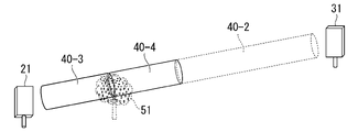
- FIG. It is a figure which shows an example (the 1) of the shape of the evaluation object space in this embodiment. It is a figure which shows an example (2) of the shape of the evaluation object space in this embodiment. It is a figure which shows an example (3) of the shape of the evaluation object space in this embodiment. It is a figure which shows the example of division
- 4 is a flow chart showing the flow of processing performed by the station placement design device according to the present embodiment;
- FIG. 4 is a diagram showing a process (part 1) of division of an evaluation target space performed by the station placement design device according to the present embodiment;
- FIG. 10 is a diagram showing a process (part 2) of division of an evaluation target space performed by the station placement design device according to the present embodiment
- FIG. 11 is a diagram showing a process (part 3) of division of an evaluation target space performed by the station placement design device according to the present embodiment
- FIG. 10 is a diagram showing a process (part 4) of dividing an evaluation target space performed by the station placement design device according to the present embodiment
- FIG. 1 is a block diagram showing the configuration of a station placement design device 1 according to one embodiment of the present invention.
- the station placement design device 1 includes a wireless station candidate position data storage unit 10, a point cloud data storage unit 13, a candidate position selection unit 14, an evaluation target space setting unit 15, a point cloud data amount detection unit 16, a determination unit 17, and an evaluation target.
- a space division unit 18 is provided.
- the wireless station candidate location data storage unit 10 includes a wireless base station candidate location data storage unit 11 and a wireless terminal station candidate location data storage unit 12 .
- the wireless base station candidate position data storage unit 11 stores wireless base station candidate position data in advance.
- the radio base station candidate position data is data indicating candidate positions for installing the radio base station apparatus in the three-dimensional space.
- the wireless terminal station candidate position data storage unit 12 stores wireless terminal station candidate position data in advance.
- the wireless terminal station candidate position data is data indicating candidate positions for installing the wireless terminal station apparatus in the three-dimensional space.
- each of the radio base station candidate position data and each of the radio terminal station candidate position data are, for example, three-dimensional coordinate data indicating the position of one point in a three-dimensional spatial coordinate system.
- the point cloud data storage unit 13 stores point cloud data in advance.
- the point cloud data stored in the point cloud data storage unit 13 are three-dimensional coordinates indicating the position in the three-dimensional space of the reflection point when the laser light irradiated to the three-dimensional space reaches the shield and is reflected. Data.
- Point cloud data is defined as data containing one or more pieces of three-dimensional coordinate data, but in reality it is data containing a huge number of three-dimensional coordinate data.
- Each piece of three-dimensional coordinate data included in the point cloud data indicates one point on the shield that reflects the laser beam. Therefore, when the point cloud data is displayed in a three-dimensional coordinate system, the shape of the shield is represented by points.
- the three-dimensional coordinate system of the point cloud data stored in the point cloud data storage unit 13 the wireless base station candidate location data stored in the wireless base station candidate location data storage unit 11, and the wireless terminal station candidate location data storage unit 12 It is assumed that the three-dimensional coordinate system of the wireless terminal station candidate position data stored by is consistent with the three-dimensional coordinate system.
- Candidate position selection unit 14 selects any one radio base station candidate position data to be determined from radio base station candidate position data storage unit 11 and any one of radio terminal station candidate position data storage unit 12 to be determined. Select one wireless terminal station candidate position data.
- the evaluation space setting unit 15 sets a three-dimensional evaluation space predetermined between two candidate positions indicated by each of the radio base station candidate position data and the radio terminal station candidate position data selected by the candidate position selection unit 14. set.
- FIG. 2 shows the evaluation between the candidate position 21 and the candidate position 31 when the position indicated by the radio base station candidate position data is the candidate position 21 and the position indicated by the radio terminal station candidate position data is the candidate position 31.
- 4 is a diagram showing an example in which a target space setting unit 15 sets a cylindrical evaluation target space 40.
- FIG. Other examples of the three-dimensional shape of the evaluation space include, for example, a rectangular parallelepiped evaluation space 40a shown in FIG. 3 and a triangular pyramid-shaped evaluation space 40b shown in FIG.
- FIGS. 2 to 4 show the shape of the radio base station apparatus and the shape of the radio terminal station apparatus at each of the candidate positions 21 and 31 for the sake of clarity. and candidate positions 31 are actually one point in a three-dimensional coordinate system.
- the evaluation target spaces 40, 40a, and 40b are shown separated from the candidate position 21 and the candidate position 31 for ease of viewing.
- the evaluation target spaces 40, 40a, and 40b are three-dimensional shapes that include line segments that connect the candidate positions 21 and 31 and that the candidate positions 21 and 31 appear on the surface. .
- the three-dimensional shapes of the evaluation target spaces such as the evaluation target spaces 40, 40a, and 40b may be cylinders, rectangular parallelepipeds, and cones other than triangular pyramids.
- a three-dimensional shape formed by rotating an arbitrary two-dimensional shape having a line segment as one side about a line segment connecting the candidate position 21 and the candidate position 31 as a rotation axis may be used.
- the shape of the space to be evaluated is preferably a shape with a line segment connecting the candidate position 21 and the candidate position 31 as a central axis. It may be a shape that is formed.
- the point cloud data amount detection unit 16 detects the point cloud included in the evaluation target space set by the evaluation target space setting unit 15 or the evaluation target space dividing unit 18 from the point cloud data stored in the point cloud data storage unit 13. Extract data. For example, the point cloud data amount detection unit 16 counts the number of three-dimensional coordinate data included in the extracted point cloud data, and detects the counted number as the point cloud data amount.
- the determination unit 17 Based on the amount of point cloud data detected by the point cloud data amount detection unit 16 and a predetermined threshold value, the determination unit 17 detects the amount of point cloud data detected by the point cloud data amount detection unit 16 in the evaluation target space. Determine if an object exists.
- the evaluation target space dividing unit 18 sets the evaluation target space in which the determination unit 17 has determined that an obstacle exists as the evaluation target space to be divided, and divides the evaluation target space to be divided according to the size of the evaluation target space to be divided. is divided. When determining to divide, the evaluation target space dividing unit 18 divides the evaluation target space to be divided into two spaces, and sets each of the two divided spaces as a new evaluation target space. When the evaluation target space dividing unit 18 determines not to divide the evaluation target space, the evaluation target space division unit 18 outputs information regarding the evaluation target space to be divided which is not divided.
- the evaluation target space in which the determination unit 17 determines that an obstacle exists is the cylindrical evaluation target space 40 shown in FIG.
- the evaluation target space 40 has a cylindrical shape with a line segment connecting the candidate position 21 and the candidate position 31 as a central axis.
- the evaluation target space dividing unit 18 determines to divide, the evaluation target space is arranged as shown in FIG. 40 is divided into two spaces 40-1 and 40-2.
- a line segment 60 connecting the candidate position 21 and the candidate position 31 is the central axis of the evaluation target space 40.
- from the position 61 to the candidate position 31 have the same length.
- the evaluation target space dividing unit 18 sets each of the two divided spaces 40-1 and 40-2 as new evaluation target spaces 40-1 and 40-2.
- FIG. 6 is a flow chart showing the flow of processing performed by the station placement design device 1.
- Candidate position selection unit 14 selects any one radio base station candidate position data to be determined from radio base station candidate position data storage unit 11 in response to a selection operation by the user of station placement design device 1 (step S1).
- the candidate position selection unit 14 selects any one wireless terminal station candidate position data to be determined from the wireless terminal station candidate position data storage unit 12 in response to a selection operation by the user of the station placement design device 1 .
- the candidate position selection unit 14 outputs the selected wireless base station candidate position data and wireless terminal station candidate position data to the evaluation target space setting unit 15 (step S2).
- the position indicated by the radio base station candidate position data selected by the candidate position selector 14 is the candidate position 21, and the radio terminal station candidate position data selected by the candidate position selector 14 is indicated by the candidate position 21.
- the position is candidate position 31 .
- the evaluation space setting unit 15 sets a predetermined three-dimensional evaluation space between the two candidate positions 21 and 31 .
- the evaluation target space setting unit 15 has set a cylindrical evaluation target space 40 whose central axis is a line segment connecting the candidate positions 21 and 31 .
- a shielding object 51 such as a tree exists in the evaluation target space 40 .
- the evaluation target space setting unit 15 outputs data indicating the set evaluation target space 40 to the point cloud data amount detection unit 16 (step S3).
- the data indicating the evaluation target space 40 is, for example, data specifying the three-dimensional shape of the evaluation target space 40 in the three-dimensional coordinate system.
- This data includes data indicating that there is, data indicating the radius of the cylindrical bottom surface, and three-dimensional coordinate data of the candidate position 21 and the candidate position 31 in the three-dimensional coordinate system.
- the point cloud data amount detection unit 16 takes in data indicating the evaluation space 40 output by the evaluation space setting unit 15 .
- the number of data indicating the evaluation target space captured by the point cloud data amount detection unit 16 is one, that is, only data indicating the evaluation target space 40. Therefore, the processing of the loops L1s to L1e shown in FIG. It will be done only once.
- the point cloud data amount detection unit 16 specifies the space range of the evaluation target space 40 based on the captured data indicating the evaluation target space 40, and stores point cloud data existing in the specified space range. By reading from the unit 13, point cloud data in the evaluation target space 40 is extracted (step S4).
- the point cloud data amount detection unit 16 counts the number of three-dimensional coordinate data included in the extracted point cloud data, and detects the counted number as the point cloud data amount.
- the point cloud data amount detection unit 16 outputs the detected point cloud data amount and data indicating the evaluation target space 40 corresponding to the detected point cloud data amount to the determination unit 17 (step S5).
- the determination unit 17 takes in the point cloud data amount output by the point cloud data amount detection unit 16 and data indicating the evaluation target space 40 corresponding to the point cloud data amount. The determination unit 17 determines whether or not the amount of captured point cloud data is equal to or greater than a predetermined threshold (step S7). When the determining unit 17 determines that the amount of point cloud data that has been taken in is not equal to or greater than the predetermined threshold value (step S6, No), the process exits the loops L1s to L1e and proceeds to step S9.
- step S6 determines that the amount of captured point cloud data is equal to or greater than the predetermined threshold value.
- step S7 the determining unit 17 stores the captured evaluation target space 40 in the internal storage area. is written and recorded (step S7), the loop L1s-L1e is exited, and the process proceeds to step S9.
- the determination unit 17 determines that the captured point cloud data amount is equal to or greater than a predetermined threshold value, that is, "Yes", and indicates the captured evaluation target space 40. It is assumed that data is written and recorded in an internal storage area.
- the determination unit 17 determines whether the number of data indicating the evaluation target space stored in the internal storage area is 0, 1, or plural (step S9).
- the determining unit 17 determines that the number of data indicating the evaluation target space stored in the internal storage area is 0 (step S9, “0”), it is determined that there is no shielding object in the evaluation target space.
- output to the outside information indicating that there is a line of sight between the candidate position 21 of the radio base station device selected by the candidate position selection unit 14 and the candidate position 31 of the radio terminal station device step S10, End the process.
- the output to the outside in step S10 means, for example, that the determination unit 17 displays the candidate positions 21 of the radio base station apparatus and the candidates of the radio terminal station apparatus on a display or the like that the user of the station placement design apparatus 1 can refer to. It is to display information indicating that there is a line of sight between the position 31 and the position 31 .
- step S9 determines that the number of data indicating the evaluation target space stored in the internal storage area is one (step S9, "1")
- one evaluation is stored in the internal storage area.
- Data indicating the target space is output to the evaluation target space division unit 18 as data indicating the evaluation target space to be divided.
- the determination unit 17 deletes and initializes the data indicating the evaluation target space stored in the internal storage area.
- step S9 determines that the number of data indicating the evaluation target space stored in the internal storage area is plural (step S9, "plural")
- the determination unit 17 determines that the number of evaluation objects stored in the internal storage area is plural. From the data representing the target space, data representing the evaluation target space to be divided is selected from among the data representing a plurality of evaluation target spaces according to a predetermined condition.
- the determination unit 17 outputs data indicating the selected evaluation target space to be divided to the evaluation target space dividing unit 18 .
- the determination unit 17 deletes and initializes the data indicating the evaluation target space stored in the internal storage area (step S11). .
- the storage area inside the determination unit 17 stores only data indicating the evaluation target space 40 . Therefore, in the process of step S9, the determination unit 17 determines that the number of data indicating the detected evaluation target space is "1", and divides the data indicating the evaluation target space 40 stored in the internal storage area. It is output to the evaluation target space division unit 18 as a target.
- the evaluation target space dividing unit 18 takes in data indicating the evaluation target space 40 to be divided output by the determination unit 17 . Based on the acquired data indicating the evaluation target space 40 to be divided, the evaluation target space dividing unit 18 determines whether the length of the central axis of the evaluation target space 40 to be divided exceeds a predetermined length. is determined (step S12).
- the evaluation target space dividing unit 18 determines that the length of the central axis of the evaluation target space 40 to be divided does not exceed the predetermined length (Step S12, No), the evaluation target space 40 to be divided is output to the outside (step S14), and the process ends.
- the evaluation target space dividing unit 18 determines that the length of the central axis of the evaluation target space 40 to be divided exceeds the predetermined length (step S12, Yes)
- the evaluation target to be divided The space 40 is divided into two spaces so that the central axes of the two spaces after division have the same length.
- the evaluation target space dividing unit 18 sets each of the divided spaces as a new evaluation target space, outputs data indicating the two new evaluation target spaces to the point cloud data amount detection unit 16 (step S13), and then again Processing of loops L1s to L1e is performed.
- the evaluation target space dividing unit 18 determines that the length of the central axis of the evaluation target space 40 exceeds a predetermined length, that is, "Yes", and determines that "Yes” in step S13.
- the evaluation target space 40 to be divided is divided into two spaces as shown in FIG.
- the evaluation target space dividing unit 18 sets each of the two divided spaces as new evaluation target spaces 40-1 and 40-2, and sets the data representing each of the evaluation target spaces 40-1 and 40-2 as the point cloud data amount. Output to the detection unit 16 .
- the point cloud data amount detection unit 16 takes in data indicating each of the evaluation target spaces 40-1 and 40-2 output by the evaluation target space dividing unit 18.
- FIG. Since the point cloud data amount detection unit 16 takes in data indicating two evaluation target spaces, data indicating the evaluation target space 40-1 and data indicating the evaluation target space 40-2, the processing of the loops L1s to L1e is It is done twice.
- the point cloud data amount detection unit 16 and the determination unit 17 perform the processing of steps S4 to S6 on the data representing the evaluation target space 40-1.
- step S6 determines that the amount of point cloud data corresponding to the evaluation target space 40-1 is equal to or greater than the threshold, that is, "Yes", and in the process of step S7 , data indicating the evaluation target space 40-1 is written and recorded in the internal storage area.
- the point cloud data amount detection unit 16 and the determination unit 17 perform the processing of steps S4 to S6 on the data representing the evaluation target space 40-2. As shown in FIG. 8, no shield exists in the evaluation target space 40-2. Therefore, in the processing of step S6, the determination unit 17 determines that the amount of point cloud data corresponding to the evaluation target space 40-1 is not equal to or greater than the threshold value, that is, "No".
- the determination unit 17 When the processing of loops L1s to L1e is completed, the determination unit 17 performs the processing of step S9.
- the storage area inside the determination unit 17 stores only data indicating the evaluation target space 40-1. Therefore, in the processing of step S9, the determination unit 17 determines that the number of data indicating the detected evaluation target space is "1", and the data indicating the evaluation target space 40-1 stored in the internal storage area is output to the evaluation target space division unit 18 as a division target.
- the evaluation target space dividing unit 18 takes in the data indicating the evaluation target space 40-1 output by the determination unit 17.
- the evaluation target space dividing unit 18 determines that the length of the central axis of the evaluation target space 40-1 exceeds a predetermined length, that is, "Yes", and determines that step In the process of S13, the evaluation space 40-1 to be divided is divided into two spaces as shown in FIG.
- the evaluation target space dividing unit 18 sets each of the two divided spaces as new evaluation target spaces 40-3 and 40-4, and sets the data representing each of the evaluation target spaces 40-3 and 40-4 as the point cloud data amount. Output to the detection unit 16 .
- the point cloud data amount detection unit 16 takes in data indicating each of the evaluation target spaces 40-3 and 40-4 output by the evaluation target space dividing unit 18.
- FIG. Since the point cloud data amount detection unit 16 takes in data indicating two evaluation target spaces, data indicating the evaluation target space 40-3 and data indicating the evaluation target space 40-4, the processing of the loops L1s to L1e is It will be done twice.
- the point cloud data amount detection unit 16 and the determination unit 17 perform steps S4 to S6 on the data representing the evaluation target space 40-3.
- step S6 the determination unit 17 determines that the point cloud data amount corresponding to the evaluation target space 40-3 is equal to or greater than the threshold, that is, "Yes", and in the process of step S7 , data indicating the evaluation target space 40-3 is written and recorded in the internal storage area.
- the point cloud data amount detection unit 16 and the determination unit 17 perform steps S4 to S6 on the data representing the evaluation target space 40-4. As shown in FIG. 9, a portion of the shield 51 also exists in the evaluation target space 40-4. Therefore, here too, in the process of step S6, the determination unit 17 determines that the point cloud data amount corresponding to the evaluation target space 40-4 is equal to or greater than the threshold, that is, "Yes", and in the process of step S7 , data indicating the evaluation target space 40-4 is written and recorded in the internal storage area.
- the determination unit 17 When the processing of loops L1s to L1e is completed, the determination unit 17 performs the processing of step S9.
- the storage area inside the determination unit 17 stores data indicating the evaluation target space 40-3 and data indicating the evaluation target space 40-4. Therefore, in the process of step S9, the determination unit 17 determines that the number of data indicating the detected evaluation target space is "plural", and performs the process of step S11.
- the predetermined condition in the process of step S11 is to select data indicating the evaluation target space closest to the candidate position 21 indicated by the wireless base station candidate position data.
- the determination unit 17 selects the data representing the evaluation target space 40-3 stored in the internal storage area as a division target.
- the determination unit 17 outputs data indicating the selected evaluation target space 40-3 to the evaluation target space dividing unit 18.
- FIG. The evaluation target space dividing unit 18 takes in the data indicating the evaluation target space 40-3 output by the determination unit 17.
- the evaluation target space dividing unit 18 determines that the length of the central axis of the evaluation target space 40-3 exceeds a predetermined length, that is, "Yes".
- the evaluation target space 40-3 to be divided is divided into two spaces as shown in FIG.
- the evaluation target space dividing unit 18 sets each of the two divided spaces as new evaluation target spaces 40-5 and 40-6, and sets the data representing each of the evaluation target spaces 40-5 and 40-6 as the point cloud data amount. Output to the detection unit 16 .
- the point cloud data amount detection unit 16 takes in data indicating each of the evaluation target spaces 40-5 and 40-6 output by the evaluation target space dividing unit 18.
- FIG. Since the point cloud data amount detection unit 16 takes in data indicating two evaluation target spaces, data indicating the evaluation target space 40-5 and data indicating the evaluation target space 40-6, the processing of the loops L1s to L1e is It will be done twice.
- the point cloud data amount detection unit 16 and the determination unit 17 perform the processing of steps S4 to S6 on the data representing the evaluation target space 40-5.
- the determination unit 17 determines that the amount of point cloud data corresponding to the evaluation target space 40-5 is not equal to or greater than the threshold value, that is, "No".
- the point cloud data amount detection unit 16 and the determination unit 17 perform the processing of steps S4 to S6 on the data representing the evaluation target space 40-6. As shown in FIG. 10, part of the shield 51 exists in the evaluation target space 40-6. Therefore, here, in the process of step S6, the determination unit 17 determines that the point cloud data amount corresponding to the evaluation target space 40-6 is equal to or greater than the threshold, that is, "Yes", and in the process of step S7 , data indicating the evaluation target space 40-6 is written and recorded in the internal storage area.
- the determination unit 17 When the processing of loops L1s to L1e is completed, the determination unit 17 performs the processing of step S9.
- the storage area inside the determination unit 17 stores only data indicating the evaluation target space 40-6. Therefore, in the process of step S9, the determination unit 17 determines that the number of data indicating the detected evaluation target space is "1", and the data indicating the evaluation target space 40-6 stored in the internal storage area is output to the evaluation target space division unit 18 as a division target.
- the evaluation target space dividing unit 18 takes in the data indicating the evaluation target space 40-6 output by the determination unit 17.
- the evaluation target space division unit 18 takes in the data indicating the evaluation target space 40-6 output by the determination unit 17.
- the length of the central axis of the evaluation target space 40-6 does not exceed a predetermined length. Therefore, in the process of step S12, the evaluation target space dividing unit 18 determines that the length of the center axis of the evaluation target space 40-6 does not exceed a predetermined length, ie, "No", and In the process of S14, the data representing the evaluation space 40-6, which is the evaluation space to be divided which has not been divided, is output to the outside.
- the output to the outside in step S14 is, for example, a state in which the evaluation target space 40 as shown in FIG. is displayed, and the evaluation target space 40-6, which is finally divided, is displayed in a color different from the evaluation target spaces 40-2, 40-4, and 40-5.
- the determination unit 17 selects the data indicating the evaluation target space closest to the candidate position indicated by the wireless base station candidate position data as the predetermined condition.
- An applied example is shown.
- a predetermined condition a condition that the determination unit 17 selects data indicating all evaluation target spaces stored in the internal storage area may be applied.
- the processing of step S ⁇ b>12 is performed on the data indicating all the evaluation target spaces stored in the internal storage area of the determination unit 17 .
- the evaluation target space dividing unit 18 divides the evaluation target space 40 between the candidate position 21 and the candidate position 31 to create a space in which the amount of point cloud data is equal to or greater than the threshold. , and the length of the center axis of which is equal to or less than a predetermined length is detected.
- the station placement design device 1 of the above embodiment includes a radio base station candidate position data storage unit 11 that stores radio base station candidate position data indicating candidate positions for installing a radio base station device in a three-dimensional space; A wireless terminal station candidate position data storage unit 12 for storing wireless terminal station candidate position data indicating candidate positions for installing wireless terminal station devices in the original space, and a point cloud data storage unit 13 for storing point cloud data, which is data indicating the position in the three-dimensional space of the reflection point when it reaches and reflects.
- Candidate position selection unit 14 selects any one radio base station candidate position data from radio base station candidate position data storage unit 11, and selects any one radio terminal station candidate position data from radio terminal station candidate position data storage unit 12. Select data.
- the evaluation target space setting unit 15 is a space between candidate positions indicated by the radio base station candidate position data and the radio terminal station candidate position data selected by the candidate position selector 14, and is a line segment connecting the two candidate positions.
- a space surrounded by a predetermined three-dimensional shape including is set as an evaluation target space.
- the point cloud data amount detection unit 16 detects the amount of point cloud data existing in the set evaluation target space based on the point cloud data stored in the point cloud data storage unit 13 . Based on the amount of point cloud data detected by the point cloud data amount detection unit 16 and a predetermined threshold value, the determination unit 17 determines whether or not there is a shield in the evaluation target space.
- the evaluation target space dividing unit 18 sets the evaluation target space in which the determination unit 17 has determined that an obstacle exists as the evaluation target space to be divided, and divides the evaluation target space to be divided according to the size of the evaluation target space to be divided. If it is determined to divide, the evaluation target space to be divided is divided into two spaces, and each of the two divided spaces is set as a new evaluation target space. If determined, the information regarding the evaluation target space to be divided which was not divided is output. As a result, it is possible to narrow down to the point cloud data included in the evaluation target space finally output by the evaluation target space dividing unit 18, and perform the three-dimensional visibility determination processing. can be shortened.
- the station placement design device 1 divides the evaluation target space until the length of the central axis of the evaluation target space is equal to or less than a predetermined length. repeat.
- the evaluation space 40 is calculated from the candidate position 21 indicated by the wireless base station candidate position data. Since it is known that there is a line of sight in the evaluation space 40-5 up to -6, it is possible to determine the range of radio waves transmitted by the radio base station apparatus. Since it is specified that the number of three-dimensional coordinate data included in the point cloud data corresponding to the shielding object 51 is greater than or equal to the threshold in the evaluation space 40-6, it is included in the evaluation space 40-6. By focusing on the point cloud data and performing the stereoscopic visibility determination process, it is possible to shorten the time required for the visibility determination process.
- the point cloud data amount detection unit 16 extracts the point cloud data in the evaluation target space, counts the number of three-dimensional coordinate data included in the extracted point cloud data, and counts the number is detected as the amount of point cloud data.
- the point cloud data amount detection unit 16 may write the extracted point cloud data in an internal storage area, and detect the capacity of the internal storage area after writing as the point cloud data amount.
- the unit of the threshold predetermined in the determination unit 17 is not the number but the value indicating the capacity.
- the determination unit 17 applies a predetermined threshold value in the process of step S6.
- a threshold corresponding to the volume of the evaluation target space may be applied.
- the determination unit 17 can apply a threshold according to the size of the evaluation target space to be determined by doing the following.
- the determination unit 17 pre-stores in an internal storage area a table that associates a plurality of evaluation target space size ranges with thresholds applied to each evaluation target space size range.
- the determination unit 17 determines based on the captured evaluation target space data. to specify the size of the space to be evaluated.
- the determination unit 17 refers to the table stored in the internal storage area and selects a threshold value corresponding to the size of the specified evaluation target space, thereby applying the selected threshold value in the process of step S6. .
- step S11 As shown in the above embodiment, as a predetermined condition for the process of step S11, the condition that data indicating the evaluation target space closest to the candidate position indicated by the wireless base station candidate position data is selected is applied.
- the processing of the flowchart shown in FIG. 6 may be changed to the following processing.
- the determination processing in step S9 the determination unit 17 performs determination processing as to whether the number is “0” or “1” without determining the case of “plural”.
- the data indicating the evaluation target space closer to the candidate position indicated by the base station candidate position data is processed in steps S4 to S6 first.
- the determining unit 17 When the determining unit 17 first determines “Yes” in the process of step S6 and then performs the process of step S7, the data indicating the evaluation target space recorded in the internal storage area of the determining unit 17 is , data indicating the evaluation target space closest to the candidate position indicated by the radio base station candidate position data. Therefore, the determination unit 17 first writes and records the data indicating the evaluation target space in the process of step S7, and then exits the process of loops L1s to L1e. By doing so, it becomes unnecessary to perform the subsequent steps S4 to S6 in the processing of the loops L1s to L1e. is eliminated, the processing load can be reduced.
- the evaluation target space dividing unit 18 determines whether or not the length of the central axis of the evaluation target space exceeds a predetermined length in the process of step S12. On the other hand, it is determined whether a parameter indicating the size of the evaluation space other than the length of the central axis of the evaluation space, such as the volume of the evaluation space, exceeds a predetermined value. A determination may be made. In this case, the evaluation target space dividing unit 18 also applies the parameter to the process of step S13, and divides the two spaces so that the parameters indicating the size of each of the two spaces after division are the same.
- the evaluation target space dividing unit 18 determines whether or not the volume of the evaluation target space exceeds a predetermined volume in the processing of step S12, and determines whether or not the volume of the evaluation target space exceeds a predetermined volume in the processing of step S13.
- the three-dimensional shape of the evaluation target space is the candidate position of the wireless base station selected by the candidate position selection unit 14 and the wireless terminal station. Any shape may be applied as long as it includes a line segment connecting the candidate positions of .
- the data indicating the candidate positions of the radio base station apparatus are stored in the radio base station candidate position data storage section 11, and the data indicating the candidate positions of the radio terminal station apparatus are stored in the radio terminal station candidate position data storage section 12.
- the candidate positions of the radio station devices may be stored in the radio station candidate position data storage unit 10 regardless of the type of radio base station device or radio terminal station device.
- the candidate position selection unit 14 selects two wireless station candidate position data to be determined from the wireless station candidate position data storage unit 10 in response to the user's selection operation of the station design device 1. will do.
- the three-dimensional coordinate system of the point cloud data stored in the point cloud data storage unit 13 the wireless base station candidate position data and the wireless terminal station candidate position data stored in the wireless base station candidate position data storage unit 11 It is assumed that the three-dimensional coordinate system of the wireless terminal station candidate position data stored in the storage unit 12 matches the three-dimensional coordinate system of the point cloud data stored in the point cloud data storage unit 13 and the wireless base station candidate position data.
- the three-dimensional coordinate system of the wireless base station candidate position data stored in the candidate position data storage unit 11 and the wireless terminal station candidate position data stored in the wireless terminal station candidate position data storage unit 12 may be different.
- the point cloud data amount detection unit 16 converts the data indicating the evaluation target space received from the evaluation target space setting unit 15 or the evaluation target space dividing unit 18 into the point cloud data stored in the point cloud data storage unit 13. , and using the data representing the converted evaluation space, point cloud data in the evaluation space is extracted.
- determination processing using an inequality sign or an inequality sign with an equal sign is performed in the processing shown in steps S6 and S12.
- the present invention is not limited to this embodiment. may be replaced with determination processing of “whether it exceeds” and “whether it is greater than or equal to”, respectively.
- the station placement design device 1 in the above-described embodiment may be realized by a computer.
- a program for realizing this function may be recorded in a computer-readable recording medium, and the program recorded in this recording medium may be read into a computer system and executed.
- the "computer system” referred to here includes hardware such as an OS and peripheral devices.
- the term "computer-readable recording medium” refers to portable media such as flexible discs, magneto-optical discs, ROMs and CD-ROMs, and storage devices such as hard discs incorporated in computer systems.
- “computer-readable recording medium” means a medium that dynamically retains a program for a short period of time, like a communication line when transmitting a program via a network such as the Internet or a communication line such as a telephone line. It may also include something that holds the program for a certain period of time, such as a volatile memory inside a computer system that serves as a server or client in that case. Further, the program may be for realizing a part of the functions described above, or may be capable of realizing the functions described above in combination with a program already recorded in the computer system. It may be implemented using a programmable logic device such as an FPGA (Field Programmable Gate Array).
- FPGA Field Programmable Gate Array
- It can be used for station placement design using 3D point cloud data.
- Reference Signs List 1 station placement design device 10 wireless station candidate position data storage unit 11 wireless base station candidate position data storage unit 12 wireless terminal station candidate position data storage unit 13 point cloud data storage unit 14 candidates Position selection unit 15 Evaluation space setting unit 16 Point cloud data amount detection unit 17 Judgment unit 18 Evaluation space division unit
Landscapes
- Engineering & Computer Science (AREA)
- Computer Networks & Wireless Communication (AREA)
- Signal Processing (AREA)
- Mobile Radio Communication Systems (AREA)
- Radar Systems Or Details Thereof (AREA)
Abstract
2つの無線局候補位置データを選択し、選択した2つの無線局候補位置データの各々が示す候補位置の間の空間であって2つの候補位置を結ぶ線分を含む予め定められる三次元形状によって囲まれる空間を評価対象空間として設定し、設定した評価対象空間内に存在する点群データの量を検出し、検出した点群データの量と、予め定められる閾値とに基づいて、評価対象空間内に遮蔽物が存在するか否かを判定し、遮蔽物が存在すると判定された評価対象空間を分割対象の評価対象空間とし、分割対象の評価対象空間の大きさに応じて、分割対象の評価対象空間を分割するか否かを判定し、分割すると判定した場合、分割対象の評価対象空間を2つの空間に分割し、分割した2つの空間の各々を新たな評価対象空間として設定し、分割しないと判定した場合、分割しなかった分割対象の評価対象空間に関する情報を出力する。
Description
本発明は、点群データを用いて置局設計を行う置局設計方法及び置局設計装置に関する。
通信インフラである通信網に対してミリ波を活用するユースケースの提案が、IEEE(Institute of Electrical and Electronics Engineer)802.11ayにおいて行われている(例えば、非特許文献1参照)。ミリ波帯や準ミリ波帯等の高い周波数帯を利用して無線インフラを構築する取り組みが進められている。
ミリ波帯や準ミリ波帯等の高い周波数帯では、電波の直進性が高く、回折等による電波の回り込みが期待できないため、遮蔽物の影響によって電波の到達に大きく影響を受けてしまう。そのため、従来の置局設計では、2つの無線局装置それぞれを設置する候補となる候補位置の間を直線で結んだ見通し線上に遮蔽物が存在するか否かに基づいて候補位置の間の見通し判定を行っていた。そして、従来の置局設計では、見通し判定の結果に基づいて、どの候補位置に無線局装置を設置するかを決めていた(例えば、特許文献1参照)。
上記の従来の置局設計では、見通し線上に遮蔽物が存在する場合、一律に通信ができないと判定してしまうという問題がある。これに対して、通信インフラの設備を監視するために、三次元の点群データを活用することも進められている(例えば、非特許文献2参照)。三次元の点群データを利用することで、第1フレネルゾーン内の遮蔽物の影響を考慮した見通し判定を行うことが可能になる。
三次元の点群データは、例えば、以下の手順によって生成される。評価対象となる空間を移動する車両などの移動体に搭載された測定装置が、一定周期で周囲に対してレーザ光を照射する。レーザ光が遮蔽物に到達して反射する反射波を測定装置が受信することにより、レーザ光を照射してから反射波を受けるまでのレーザ光の往復時間と、レーザ光を照射した測定装置の位置とに基づいて、遮蔽物においてレーザ光を反射した反射点の三次元空間における位置を示す三次元座標データを求めることができる。このレーザ光の照射を評価対象の空間の全体に対して行うことにより、評価対象の空間における複数の三次元座標データを含む点群データが得られることになる。
Djordje Tujkovic, "Changes to IEEE 802.11ay in support of mmW Distribution Network Use Cases", IEEE 802.11-17/1022r0. July 10th 2017,[令和3年1月4日検索],インターネット(URL: https://mentor.ieee.org/802.11/dcn/17/11-17-1022-00-00ay-changes-to-ieee-802-11ay-in-support-of-mmw-mesh-network-use-cases.pptx)
「3D点群解析技術で実世界をデータベース化します」、 NTT R&D FORUM 2017フォーラム展示資料 B-10、[令和3年1月4日検索]、インターネット(URL: https://labevent.ecl.ntt.co.jp/forum2017/elements/pdf_jpn/02/B-10_j.pdf)
しかしながら、点群データを利用して立体的に見通しを判定しようとする場合、点群データは膨大な量があるため、見通し判定の処理において、非常に長い時間を要するという問題がある。
上記事情に鑑み、本発明は、点群データを利用する立体的な見通し判定を行う際に、見通し判定の処理に要する時間を短縮することができる技術の提供を目的としている。
本発明の一態様は、三次元空間における無線局装置を設置する候補となる位置を示す無線局候補位置データを、無線局候補位置データ記憶部に記憶させる無線局候補位置データ記録ステップと、前記三次元空間に対して照射されるレーザ光が遮蔽物に到達して反射する際の反射点の前記三次元空間における位置を示すデータである点群データを、点群データ記憶部に書き込んで記憶させる点群データ記録ステップと、前記無線局候補位置データ記憶部から2つの前記無線局候補位置データを選択する候補位置選択ステップと、選択した2つの前記無線局候補位置データの各々が示す候補位置の間の空間であって2つの前記候補位置を結ぶ線分を含む予め定められる三次元形状によって囲まれる空間を評価対象空間として設定する評価対象空間設定ステップと、設定した前記評価対象空間内に存在する前記点群データの量を前記点群データ記憶部が記憶する前記点群データに基づいて検出する点群データ量検出ステップと、検出した前記点群データの量と、予め定められる閾値とに基づいて、前記評価対象空間内に前記遮蔽物が存在するか否かを判定する判定ステップと、前記判定ステップにより前記遮蔽物が存在すると判定された前記評価対象空間を分割対象の評価対象空間とし、前記分割対象の評価対象空間の大きさに応じて、前記分割対象の評価対象空間を分割するか否かを判定し、分割すると判定した場合、前記分割対象の評価対象空間を2つの空間に分割し、分割した2つの空間の各々を新たな前記評価対象空間として設定し、分割しないと判定した場合、分割しなかった前記分割対象の評価対象空間に関する情報を出力する評価対象空間分割ステップと、を含む置局設計方法である。
本発明の一態様は、三次元空間における無線局装置を設置する候補となる位置を示す無線局候補位置データを記憶する無線局候補位置データ記憶部と、前記三次元空間に対して照射されるレーザ光が遮蔽物に到達して反射する際の反射点の前記三次元空間における位置を示すデータである点群データを記憶する点群データ記憶部と、前記無線局候補位置データ記憶部から2つの前記無線局候補位置データを選択する候補位置選択部と、前記候補位置選択部が選択する2つの前記無線局候補位置データの各々が示す候補位置の間の空間であって2つの前記候補位置を結ぶ線分を含む予め定められる三次元形状によって囲まれる空間を評価対象空間として設定する評価対象空間設定部と、設定される前記評価対象空間内に存在する前記点群データの量を前記点群データ記憶部が記憶する前記点群データに基づいて検出する点群データ量検出部と、前記点群データ量検出部が検出する前記点群データの量と、予め定められる閾値とに基づいて、前記評価対象空間内に前記遮蔽物が存在するか否かを判定する判定部と、前記判定部が前記遮蔽物が存在すると判定した前記評価対象空間を分割対象の評価対象空間とし、前記分割対象の評価対象空間の大きさに応じて、前記分割対象の評価対象空間を分割するか否かを判定し、分割すると判定した場合、前記分割対象の評価対象空間を2つの空間に分割し、分割した2つの空間の各々を新たな前記評価対象空間として設定し、分割しないと判定した場合、分割しなかった前記分割対象の評価対象空間を示す情報を出力する評価対象空間分割部と、を備える置局設計装置である。
本発明により、点群データを利用する立体的な見通し判定を行う際に、見通し判定の処理に要する時間を短縮することが可能になる。
以下、本発明の実施形態について図面を参照して説明する。図1は、本発明の一実施形態における置局設計装置1の構成を示すブロック図である。置局設計装置1は、無線局候補位置データ記憶部10、点群データ記憶部13、候補位置選択部14、評価対象空間設定部15、点群データ量検出部16、判定部17及び評価対象空間分割部18を備える。
無線局候補位置データ記憶部10は、無線基地局候補位置データ記憶部11と、無線端末局候補位置データ記憶部12とを備える。無線基地局候補位置データ記憶部11は、無線基地局候補位置データを予め記憶する。無線基地局候補位置データは、三次元空間における無線基地局装置を設置する候補となる位置を示すデータである。無線端末局候補位置データ記憶部12は、無線端末局候補位置データを予め記憶する。無線端末局候補位置データは、三次元空間における無線端末局装置を設置する候補となる位置を示すデータである。ここで、無線基地局候補位置データの各々及び無線端末局候補位置データの各々は、例えば、三次元の空間座標系における1点の位置を示す三次元座標データである。
点群データ記憶部13は、点群データを予め記憶する。点群データ記憶部13に記憶される点群データは、三次元空間に対して照射されるレーザ光が遮蔽物に到達して反射する際の反射点の三次元空間における位置を示す三次元座標データである。点群データは、1つ以上の三次元座標データを含むデータとして定義されるが、実際には、膨大な数の三次元座標データを含むデータである。点群データに含まれる三次元座標データの各々は、遮蔽物におけるレーザ光を反射した1点を示すことになる。したがって、点群データを三次元座標系において表示すると、遮蔽物の形状が点によって表されることになる。ここでは、点群データ記憶部13が記憶する点群データの三次元座標系と、無線基地局候補位置データ記憶部11が記憶する無線基地局候補位置データ及び無線端末局候補位置データ記憶部12が記憶する無線端末局候補位置データの三次元座標系とは一致しているものとする。
候補位置選択部14は、無線基地局候補位置データ記憶部11から判定対象とするいずれか1つの無線基地局候補位置データと、無線端末局候補位置データ記憶部12から判定対象とするいずれか1つの無線端末局候補位置データとを選択する。
評価対象空間設定部15は、候補位置選択部14が選択した無線基地局候補位置データ及び無線端末局候補位置データの各々が示す2つの候補位置の間に予め定められる三次元形状の評価対象空間を設定する。
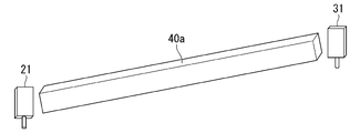
図2は、無線基地局候補位置データが示す位置が候補位置21であり、無線端末局候補位置データが示す位置が候補位置31である場合に、候補位置21と候補位置31との間に評価対象空間設定部15が、円柱形状の評価対象空間40を設定した場合の例を示す図である。評価対象空間の三次元形状の他の例としては、例えば、図3に示す直方体形状の評価対象空間40aや、図4に示す三角錐形状の評価対象空間40bなどがある。
なお、図2から図4では、分かり易さのために、候補位置21と候補位置31の各々において無線基地局装置の形状と、無線端末局装置の形状とを示しているが、候補位置21と候補位置31の各々は、実際には、三次元座標系における1点である。図2から図4では、見易くするために、評価対象空間40,40a,40bを、候補位置21と候補位置31とから離して示しているが、実際には、例えば、後述する図5に示す例のように、評価対象空間40,40a,40bは、候補位置21と候補位置31とを結ぶ線分を含み、かつ表面に候補位置21と候補位置31とが現れている三次元形状である。
そのため、評価対象空間40,40a,40b等の評価対象空間の三次元形状は、円柱や直方体や三角錐以外の円錐などの形状であってもよいし、候補位置21と候補位置31とを結ぶ線分を一辺とする任意の二次元形状を候補位置21と候補位置31とを結ぶ線分を回転軸として回転させて形成される三次元形状であってもよい。評価対象空間の形状は、候補位置21と候補位置31とを結ぶ線分を中心軸とする形状であることが望ましいが、候補位置21と候補位置31とを結ぶ線分が中心軸と平行になっている形状であってもよい。
点群データ量検出部16は、点群データ記憶部13が記憶する点群データの中から評価対象空間設定部15、または、評価対象空間分割部18が設定する評価対象空間に含まれる点群データを抽出する。点群データ量検出部16は、例えば、抽出した点群データに含まれる三次元座標データの数をカウントし、カウントした数を点群データ量として検出する。
判定部17は、点群データ量検出部16が検出した点群データ量と、予め定められる閾値とに基づいて、点群データ量検出部16が点群データ量を検出した評価対象空間において遮蔽物が存在するか否かを判定する。
評価対象空間分割部18は、判定部17が遮蔽物が存在すると判定した評価対象空間を分割対象の評価対象空間とし、分割対象の評価対象空間の大きさに応じて、分割対象の評価対象空間を分割するか否かを判定する。評価対象空間分割部18は、分割すると判定した場合、分割対象の評価対象空間を2つの空間に分割し、分割した2つの空間の各々を新たな評価対象空間として設定する。評価対象空間分割部18は、分割しないと判定した場合、分割しなかった分割対象の評価対象空間に関する情報を出力する。
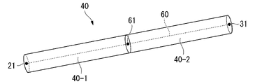
例えば、判定部17が遮蔽物が存在すると判定した評価対象空間が、図2に示す円柱形状の評価対象空間40であるとする。評価対象空間40は、候補位置21と候補位置31とを結ぶ線分を中心軸とする円柱形状であるとする。この場合、評価対象空間分割部18は、分割すると判定した場合、分割後の2つの空間の各々の中心軸の長さが同一の長さになるように、図5に示すように評価対象空間40を2つの空間40-1,40-2に分割する。なお、図5において、候補位置21と候補位置31とを結ぶ線分60が、評価対象空間40の中心軸であり、線分60上の1点である位置61から候補位置21までの長さと、位置61から候補位置31までの長さとが同一の長さである。評価対象空間分割部18は、分割した2つの空間40-1,40-2の各々を新たな評価対象空間40-1,40-2とする。
(置局設計装置1による処理)
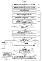
次に、図6から図10を参照しつつ置局設計装置1が行う処理について説明する。図6は、置局設計装置1が行う処理の流れを示すフローチャートである。候補位置選択部14は、置局設計装置1の利用者による選択操作を受けて、無線基地局候補位置データ記憶部11から判定対象とするいずれか1つの無線基地局候補位置データを選択する(ステップS1)。候補位置選択部14は、置局設計装置1の利用者による選択操作を受けて、無線端末局候補位置データ記憶部12から判定対象とするいずれか1つの無線端末局候補位置データを選択する。候補位置選択部14は、選択した無線基地局候補位置データと無線端末局候補位置データを評価対象空間設定部15に出力する(ステップS2)。
次に、図6から図10を参照しつつ置局設計装置1が行う処理について説明する。図6は、置局設計装置1が行う処理の流れを示すフローチャートである。候補位置選択部14は、置局設計装置1の利用者による選択操作を受けて、無線基地局候補位置データ記憶部11から判定対象とするいずれか1つの無線基地局候補位置データを選択する(ステップS1)。候補位置選択部14は、置局設計装置1の利用者による選択操作を受けて、無線端末局候補位置データ記憶部12から判定対象とするいずれか1つの無線端末局候補位置データを選択する。候補位置選択部14は、選択した無線基地局候補位置データと無線端末局候補位置データを評価対象空間設定部15に出力する(ステップS2)。
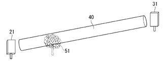
例えば、図7に示すように、候補位置選択部14が選択した無線基地局候補位置データが示す位置が、候補位置21であり、候補位置選択部14が選択した無線端末局候補位置データが示す位置が、候補位置31であるとする。
評価対象空間設定部15は、2つの候補位置21,31の間に予め定められる三次元形状の評価対象空間を設定する。ここでは、図7に示すように、評価対象空間設定部15は、候補位置21と候補位置31とを結ぶ線分を中心軸とする円柱形状の評価対象空間40を設定したとする。図7に示すように、評価対象空間40には、樹木の遮蔽物51が存在しているものとする。
評価対象空間設定部15は、設定した評価対象空間40を示すデータを点群データ量検出部16に出力する(ステップS3)。ここで、評価対象空間40を示すデータとは、例えば、三次元座標系における評価対象空間40の三次元形状を特定するデータであり、円柱形状の評価対象空間40の場合、例えば、円柱形状であることを示すデータと、円柱形状の底面の半径を示すデータと、三次元座標系における候補位置21と候補位置31の三次元座標データとを含むデータである。
点群データ量検出部16は、評価対象空間設定部15が出力する評価対象空間40を示すデータを取り込む。ここでは、点群データ量検出部16が取り込む評価対象空間を示すデータの数は、1個、すなわち評価対象空間40を示すデータのみであるため、図6に示すループL1s~L1eの処理は、一度だけ行われることになる。
点群データ量検出部16は、取り込んだ評価対象空間40を示すデータに基づいて、評価対象空間40の空間の範囲を特定し、特定した空間の範囲に存在する点群データを点群データ記憶部13から読み出すことにより、評価対象空間40内の点群データを抽出する(ステップS4)。
点群データ量検出部16は、抽出した点群データに含まれる三次元座標データの数をカウントし、カウントした数を点群データ量として検出する。点群データ量検出部16は、検出した点群データ量と、検出した点群データ量に対応する評価対象空間40を示すデータとを判定部17に出力する(ステップS5)。
判定部17は、点群データ量検出部16が出力する点群データ量と、当該点群データ量に対応する評価対象空間40を示すデータとを取り込む。判定部17は、取り込んだ点群データ量が、予め定められる閾値以上であるか否かを判定する(ステップS7)。判定部17は、取り込んだ点群データ量が、予め定められる閾値以上でないと判定した場合(ステップS6、No)、ループL1s~L1eを抜けて、ステップS9に処理が進められる。
一方、判定部17は、取り込んだ点群データ量が、予め定められる閾値以上であると判定した場合(ステップS6、Yes)、判定部17は、内部の記憶領域に、取り込んだ評価対象空間40を示すデータを書き込んで記録し(ステップS7)、ループL1s~L1eを抜けて、ステップS9に処理が進められる。
評価対象空間40の場合、図7に示すように、遮蔽物51が存在している。そのため、ここでは、判定部17は、ステップS6の処理において、取り込んだ点群データ量が、予め定められる閾値以上である、すなわち「Yes」であると判定し、取り込んだ評価対象空間40を示すデータを内部の記憶領域に書き込んで記録するものとする。
判定部17は、内部の記憶領域が記憶する評価対象空間を示すデータの数が、0個であるか、1個であるか、複数個であるかを判定する(ステップS9)。判定部17は、内部の記憶領域が記憶する評価対象空間を示すデータの数が0個であると判定した場合(ステップS9、「0個」)、評価対象空間において遮蔽物が存在しないこと、言い換えると、候補位置選択部14が選択した無線基地局装置の候補位置21と、無線端末局装置の候補位置31との間に見通しがあることを示す情報を外部に出力し(ステップS10)、処理を終了する。なお、ステップS10における外部への出力とは、例えば、判定部17が、置局設計装置1の利用者が参照可能なディスプレイなどに無線基地局装置の候補位置21と、無線端末局装置の候補位置31との間に見通しがあることを示す情報を表示することである。
判定部17は、内部の記憶領域が記憶する評価対象空間を示すデータの数が1個であると判定した場合(ステップS9、「1個」)、内部の記憶領域が記憶する1個の評価対象空間を示すデータを分割対象の評価対象空間を示すデータとして評価対象空間分割部18に出力する。判定部17は、分割対象の評価対象空間を示すデータを評価対象空間分割部18に出力した後、内部の記憶領域が記憶する評価対象空間を示すデータを削除して初期化する。
判定部17は、内部の記憶領域が記憶する評価対象空間を示すデータの数が複数個であると判定した場合(ステップS9、「複数個」)、内部の記憶領域が記憶する複数個の評価対象空間を示すデータから、予め定められる所定の条件にしたがって、複数個の評価対象空間を示すデータの中から分割対象の評価対象空間を示すデータを選択する。判定部17は、選択した分割対象の評価対象空間を示すデータを評価対象空間分割部18に出力する。判定部17は、分割対象の評価対象空間を示すデータを評価対象空間分割部18に出力した後、内部の記憶領域が記憶する評価対象空間を示すデータを削除して初期化する(ステップS11)。
ここでは、判定部17の内部の記憶領域は、評価対象空間40を示すデータのみを記憶している。そのため、判定部17は、ステップS9の処理において、検出した評価対象空間を示すデータの数が「1個」であると判定し、内部の記憶領域が記憶する評価対象空間40を示すデータを分割対象として評価対象空間分割部18に出力する。
評価対象空間分割部18は、判定部17が出力する分割対象の評価対象空間40を示すデータを取り込む。評価対象空間分割部18は、取り込んだ分割対象の評価対象空間40を示すデータに基づいて、分割対象の評価対象空間40の中心軸の長さが、予め定められる所定長を超えてるか否かを判定する(ステップS12)。
評価対象空間分割部18は、分割対象の評価対象空間40の中心軸の長さが、予め定められる所定長を超えていないと判定した場合(ステップS12、No)、分割対象の評価対象空間40を示すデータを外部に出力して(ステップS14)、処理を終了する。
一方、評価対象空間分割部18は、分割対象の評価対象空間40の中心軸の長さが、予め定められる所定長を超えていると判定した場合(ステップS12、Yes)、分割対象の評価対象空間40を、分割後の2つの空間の各々の中心軸の長さが同一の長さになるように2つの空間に分割する。評価対象空間分割部18は、分割した空間の各々を新たな評価対象空間とし、2つの新たな評価対象空間を示すデータを点群データ量検出部16に出力し(ステップS13)、その後、再びループL1s~L1eの処理が行われる。
ここでは、評価対象空間40の中心軸の長さが、予め定められる所定長を超えているものとする。そのため、評価対象空間分割部18は、ステップS12の処理において、評価対象空間40の中心軸の長さが、予め定められる所定長を超えている、すなわち「Yes」の判定をし、ステップS13の処理において、分割対象である評価対象空間40を、図8に示すように2つの空間に分割する。評価対象空間分割部18は、分割した2つの空間の各々を新たな評価対象空間40-1,40-2とし、評価対象空間40-1,40-2の各々を示すデータを点群データ量検出部16に出力する。
(初回の分割後の処理)
点群データ量検出部16は、評価対象空間分割部18が出力する評価対象空間40-1,40-2の各々を示すデータを取り込む。点群データ量検出部16が、評価対象空間40-1を示すデータと、評価対象空間40-2を示すデータという2つの評価対象空間を示すデータを取り込むため、ループL1s~L1eの処理が、2回行われる。最初に、点群データ量検出部16と判定部17は、評価対象空間40-1を示すデータに対して、ステップS4~S6の処理を行う。
点群データ量検出部16は、評価対象空間分割部18が出力する評価対象空間40-1,40-2の各々を示すデータを取り込む。点群データ量検出部16が、評価対象空間40-1を示すデータと、評価対象空間40-2を示すデータという2つの評価対象空間を示すデータを取り込むため、ループL1s~L1eの処理が、2回行われる。最初に、点群データ量検出部16と判定部17は、評価対象空間40-1を示すデータに対して、ステップS4~S6の処理を行う。
図8に示すように、評価対象空間40-1には遮蔽物51が存在している。そのため、ここでは、判定部17は、ステップS6の処理において、評価対象空間40-1に対応する点群データ量が、閾値以上である、すなわち「Yes」の判定をし、ステップS7の処理において、評価対象空間40-1を示すデータを内部の記憶領域に書き込んで記録するものとする。
次に、点群データ量検出部16と判定部17は、評価対象空間40-2を示すデータに対して、ステップS4~S6の処理を行う。図8に示すように、評価対象空間40-2には遮蔽物が存在していない。そのため、判定部17は、ステップS6の処理において、評価対象空間40-1に対応する点群データ量が、閾値以上でない、すなわち「No」の判定をする。
ループL1s~L1eの処理が終了すると、判定部17は、ステップS9の処理を行う。ここでは、判定部17の内部の記憶領域は、評価対象空間40-1を示すデータのみを記憶している。そのため、判定部17は、ステップS9の処理において、検出した評価対象空間を示すデータの数が「1個」であると判定し、内部の記憶領域が記憶する評価対象空間40-1を示すデータを分割対象として評価対象空間分割部18に出力する。評価対象空間分割部18は、判定部17が出力する評価対象空間40-1を示すデータを取り込む。
ここでは、評価対象空間40-1の中心軸の長さが、予め定められる所定長を超えているものとする。そのため、評価対象空間分割部18は、ステップS12の処理において、評価対象空間40-1の中心軸の長さが、予め定められる所定長を超えている、すなわち「Yes」の判定をし、ステップS13の処理において、分割対象である評価対象空間40-1を、図9に示すように2つの空間に分割する。評価対象空間分割部18は、分割した2つの空間の各々を新たな評価対象空間40-3,40-4とし、評価対象空間40-3,40-4の各々を示すデータを点群データ量検出部16に出力する。
(2回目の分割後の処理)
点群データ量検出部16は、評価対象空間分割部18が出力する評価対象空間40-3,40-4の各々を示すデータを取り込む。点群データ量検出部16が、評価対象空間40-3を示すデータと、評価対象空間40-4を示すデータという2つの評価対象空間を示すデータを取り込むため、ループL1s~L1eの処理が、2回行われることになる。最初に、点群データ量検出部16と判定部17は、評価対象空間40-3を示すデータに対して、ステップS4~S6の処理を行う。
点群データ量検出部16は、評価対象空間分割部18が出力する評価対象空間40-3,40-4の各々を示すデータを取り込む。点群データ量検出部16が、評価対象空間40-3を示すデータと、評価対象空間40-4を示すデータという2つの評価対象空間を示すデータを取り込むため、ループL1s~L1eの処理が、2回行われることになる。最初に、点群データ量検出部16と判定部17は、評価対象空間40-3を示すデータに対して、ステップS4~S6の処理を行う。
図9に示すように、評価対象空間40-3には遮蔽物51の一部が存在している。そのため、ここでは、判定部17は、ステップS6の処理において、評価対象空間40-3に対応する点群データ量が、閾値以上である、すなわち「Yes」の判定をし、ステップS7の処理において、評価対象空間40-3を示すデータを内部の記憶領域に書き込んで記録するものとする。
次に、点群データ量検出部16と判定部17は、評価対象空間40-4を示すデータに対して、ステップS4~S6の処理を行う。図9に示すように、評価対象空間40-4にも遮蔽物51の一部が存在している。そのため、ここでも、判定部17は、ステップS6の処理において、評価対象空間40-4に対応する点群データ量が、閾値以上である、すなわち「Yes」の判定をし、ステップS7の処理において、評価対象空間40-4を示すデータを内部の記憶領域に書き込んで記録するものとする。
ループL1s~L1eの処理が終了すると、判定部17は、ステップS9の処理を行う。ここでは、判定部17の内部の記憶領域は、評価対象空間40-3を示すデータと、評価対象空間40-4を示すデータとを記憶している。そのため、判定部17は、ステップS9の処理において、検出した評価対象空間を示すデータの数が「複数個」であると判定し、ステップS11の処理を行うことになる。
例えば、ステップS11の処理における予め定められる所定の条件が、例えば、無線基地局候補位置データが示す候補位置21に最も近い評価対象空間を示すデータを選択するという条件であるとする。この場合、評価対象空間40-3の方が、候補位置21に近いため、判定部17は、内部の記憶領域が記憶する評価対象空間40-3を示すデータを分割対象として選択する。判定部17は、選択した評価対象空間40-3を示すデータを評価対象空間分割部18に出力する。評価対象空間分割部18は、判定部17が出力する評価対象空間40-3を示すデータを取り込む。
ここでは、評価対象空間40-3の中心軸の長さが、予め定められる所定長を超えているものとする。そのため、評価対象空間分割部18は、ステップS12の処理において、評価対象空間40-3の中心軸の長さが、予め定められる所定長を超えている、すなわち「Yes」の判定をし、ステップS13の処理において、分割対象である評価対象空間40-3を、図10に示すように2つの空間に分割する。評価対象空間分割部18は、分割した2つの空間の各々を新たな評価対象空間40-5,40-6とし、評価対象空間40-5,40-6の各々を示すデータを点群データ量検出部16に出力する。
(3回目の分割後の処理)
点群データ量検出部16は、評価対象空間分割部18が出力する評価対象空間40-5,40-6の各々を示すデータを取り込む。点群データ量検出部16が、評価対象空間40-5を示すデータと、評価対象空間40-6を示すデータという2つの評価対象空間を示すデータを取り込むため、ループL1s~L1eの処理が、2回行われることになる。最初に、点群データ量検出部16と判定部17は、評価対象空間40-5を示すデータに対して、ステップS4~S6の処理を行う。
点群データ量検出部16は、評価対象空間分割部18が出力する評価対象空間40-5,40-6の各々を示すデータを取り込む。点群データ量検出部16が、評価対象空間40-5を示すデータと、評価対象空間40-6を示すデータという2つの評価対象空間を示すデータを取り込むため、ループL1s~L1eの処理が、2回行われることになる。最初に、点群データ量検出部16と判定部17は、評価対象空間40-5を示すデータに対して、ステップS4~S6の処理を行う。
図10に示すように、評価対象空間40-5には遮蔽物が存在していない。そのため、判定部17は、ステップS6の処理において、評価対象空間40-5に対応する点群データ量が、閾値以上でない、すなわち「No」の判定をする。
次に、点群データ量検出部16と判定部17は、評価対象空間40-6を示すデータに対して、ステップS4~S6の処理を行う。図10に示すように、評価対象空間40-6には遮蔽物51の一部が存在している。そのため、ここでは、判定部17は、ステップS6の処理において、評価対象空間40-6に対応する点群データ量が、閾値以上である、すなわち「Yes」の判定をし、ステップS7の処理において、評価対象空間40-6を示すデータを内部の記憶領域に書き込んで記録するものとする。
ループL1s~L1eの処理が終了すると、判定部17は、ステップS9の処理を行う。ここでは、判定部17の内部の記憶領域は、評価対象空間40-6を示すデータのみを記憶している。そのため、判定部17は、ステップS9の処理において、検出した評価対象空間を示すデータの数が「1個」であると判定し、内部の記憶領域が記憶する評価対象空間40-6を示すデータを分割対象として評価対象空間分割部18に出力する。評価対象空間分割部18は、判定部17が出力する評価対象空間40-6を示すデータを取り込む。
ステップS12の処理において、評価対象空間分割部18は、判定部17が出力する評価対象空間40-6を示すデータを取り込む。ここでは、評価対象空間40-6の中心軸の長さが、予め定められる所定長を超えていないものとする。そのため、評価対象空間分割部18は、ステップS12の処理において、評価対象空間40-6の中心軸の長さが、予め定められる所定長を超えていない、すなわち「No」の判定をし、ステップS14の処理において、分割しなかった分割対象の評価対象空間である評価対象空間40-6を示すデータを外部に出力する。
なお、ステップS14における外部への出力とは、例えば、判定部17が、置局設計装置1の利用者が参照可能なディスプレイなどに、図10に示すような評価対象空間40が分割された状態の図を表示した上で評価対象空間40-2,40-4,40-5とは異なる色で、最終的に分割対象となった評価対象空間40-6を表示することである。
上記の実施形態では、判定部17は、ステップS11の処理において、予め定められる所定の条件として、無線基地局候補位置データが示す候補位置に最も近い評価対象空間を示すデータを選択するという条件を適用した例を示した。これに対して、予め定められる条件として、判定部17が、内部の記憶領域が記憶する全ての評価対象空間を示すデータを選択するという条件を適用してもよい。この場合、判定部17の内部の記憶領域が記憶する全ての評価対象空間を示すデータに対してステップS12の処理が行われることになる。そして、最終的には、評価対象空間分割部18は、候補位置21と候補位置31の間の評価対象空間40を分割することにより生成される空間であって点群データ量が閾値以上であり、かつ中心軸の長さが予め定められる所定長以下の全ての空間を検出することになる。
上記の実施形態の置局設計装置1は、三次元空間における無線基地局装置を設置する候補となる位置を示す無線基地局候補位置データを記憶する無線基地局候補位置データ記憶部11と、三次元空間における無線端末局装置を設置する候補となる位置を示す無線端末局候補位置データを記憶する無線端末局候補位置データ記憶部12と、三次元空間に対して照射されるレーザ光が遮蔽物に到達して反射する際の反射点の三次元空間における位置を示すデータである点群データを記憶する点群データ記憶部13とを備える。候補位置選択部14は、無線基地局候補位置データ記憶部11からいずれか1つの無線基地局候補位置データを選択し、無線端末局候補位置データ記憶部12からいずれか1つの無線端末局候補位置データを選択する。評価対象空間設定部15は、候補位置選択部14が選択する無線基地局候補位置データと無線端末局候補位置データの各々が示す候補位置の間の空間であって2つの候補位置を結ぶ線分を含む予め定められる三次元形状によって囲まれる空間を評価対象空間として設定する。点群データ量検出部16は、設定される評価対象空間内に存在する点群データの量を点群データ記憶部13が記憶する点群データに基づいて検出する。判定部17は、点群データ量検出部16が検出する点群データの量と、予め定められる閾値とに基づいて、評価対象空間内に遮蔽物が存在するか否かを判定する。評価対象空間分割部18は、判定部17が遮蔽物が存在すると判定した評価対象空間を分割対象の評価対象空間とし、分割対象の評価対象空間の大きさに応じて、分割対象の評価対象空間を分割するか否かを判定し、分割すると判定した場合、分割対象の評価対象空間を2つの空間に分割し、分割した2つの空間の各々を新たな評価対象空間として設定し、分割しないと判定した場合、分割しなかった分割対象の評価対象空間に関する情報を出力する。これにより、評価対象空間分割部18が最終的に出力する評価対象空間に含まれる点群データに絞って、立体的な見通し判定の処理を行うことができるので、見通し判定の処理に要する時間を短縮することが可能になる。
より具体的には、上記の実施形態において示したように、置局設計装置1は、評価対象空間の中心軸の長さが予め定められる所定長以下になるまで、評価対象空間を分割することを繰り返す。そして、最終的に、判定部17が出力する評価対象空間分割部18が出力する評価対象空間40-6を示すデータに基づいて、無線基地局候補位置データが示す候補位置21から評価対象空間40-6に至るまでの評価対象空間40-5の間は、見通しがあることが分かるので、無線基地局装置が送信する無線電波の到達範囲を確定することができる。評価対象空間40-6に遮蔽物51に対応する点群データに含まれる三次元座標データの数が閾値以上、存在していることを特定しているので、評価対象空間40-6に含まれる点群データに絞って、立体的な見通し判定の処理を行うことにより、見通し判定の処理に要する時間を短縮することが可能になる。
なお、上記の実施形態では、点群データ量検出部16は、評価対象空間内の点群データを抽出し、抽出した点群データに含まれる三次元座標データの数をカウントし、カウントした数を点群データ量として検出している。これに対して、点群データ量検出部16は、抽出した点群データを内部の記憶領域に書き込み、書き込んだ後の内部の記憶領域の容量を点群データ量として検出するようにしてもよい。この場合、判定部17において予め定められる閾値の単位は、個数ではなく、容量を示す値になる。
上記の実施形態では、判定部17は、ステップS6の処理において、予め定められる閾値を適用しているが、判定対象の評価対象空間の大きさ、例えば、評価対象空間の中心軸の長さや、評価対象空間の体積に応じた閾値を適用するようにしてもよい。
より具体的には、例えば、以下のようにすることで、判定部17は、判定対象の評価対象空間の大きさに応じた閾値を適用することができる。判定部17は、内部の記憶領域に、複数の評価対象空間の大きさの範囲と、評価対象空間の大きさの範囲ごとに適用する閾値とを対応付けたテーブルを予め記憶する。判定部17は、点群データ量検出部16が出力する点群データ量と、当該点群データ量に対応する評価対象空間を示すデータを取り込んだ際、取り込んだ評価対象空間を示すデータに基づいて、評価対象空間の大きさを特定する。判定部17は、内部の記憶領域が記憶するテーブルを参照して、特定した評価対象空間の大きさに対応する閾値を選定することにより、選定した閾値をステップS6の処理において適用することができる。
上記の実施形態に示したように、ステップS11の処理の予め定められる所定の条件として、無線基地局候補位置データが示す候補位置に最も近い評価対象空間を示すデータを選択するという条件を適用する場合、図6に示したフローチャートの処理を以下のような処理に変更してもよい。ステップS9の判定処理において、判定部17は、「複数個」の場合を判定せずに、「0個」であるか、または、「1個」であるかの判定処理を行い、更に、無線基地局候補位置データが示す候補位置に近い方の評価対象空間を示すデータの方から先にステップS4~S6の処理を行う。判定部17が、最初にステップS6の処理において「Yes」の判定を行ってステップS7の処理を行った場合に、判定部17の内部の記憶領域に記録されている評価対象空間を示すデータが、無線基地局候補位置データが示す候補位置に最も近い評価対象空間を示すデータになる。そのため、判定部17は、ステップS7の処理において最初に評価対象空間を示すデータを書き込んで記録した後に、ループL1s~L1eの処理を抜けるようにする。このようにすることで、ループL1s~L1eの処理における、それ以降のステップS4~S6の処理を行わなくてもよくなり、ステップS9の処理における判定処理も「複数個」の場合を判定する必要がなくなるため、処理の負荷を軽減することができる。
上記の実施形態では、評価対象空間分割部18は、ステップS12の処理において、評価対象空間の中心軸の長さが、予め定められる所定長を超えているか否かという判定している。これに対して、評価対象空間の中心軸の長さ以外の評価対象空間の大きさを示すパラメータ、例えば、評価対象空間の体積などのパラメータが、予め定められる所定値を超えているか否かという判定を行うようにしてもよい。この場合、評価対象空間分割部18は、ステップS13の処理にも当該パラメータを適用し、分割後の2つの空間の各々の大きさを示すパラメータが同一になるように分割することになる。
なお、評価対象空間分割部18が、ステップS12の処理において、評価対象空間の体積が、予め定められる所定の体積を超えているか否かという判定を行い、ステップS13の処理において、分割後の2つの空間の各々の体積が同一になるように評価対象空間を分割する場合、評価対象空間の三次元形状として、候補位置選択部14が選択する無線基地局装置の候補位置と、無線端末局装置の候補位置とを結ぶ線分を含む三次元形状であれば、どのような形状を適用してもよいことになる。
上記の実施形態では、無線基地局装置の候補位置を示すデータを無線基地局候補位置データ記憶部11に記憶させ、無線端末局装置の候補位置を示すデータを無線端末局候補位置データ記憶部12に記憶させるようにしているが、無線基地局装置や無線端末局装置といった種類の区別なく、無線局装置の候補位置を無線局候補位置データ記憶部10に記憶させておくようにしてもよい。この場合、候補位置選択部14が、置局設計装置1の利用者の選択操作を受けて、無線局候補位置データ記憶部10から判定対象となる2つの無線局候補位置データを選択する処理を行うことになる。
上記の実施形態では、点群データ記憶部13が記憶する点群データの三次元座標系と、無線基地局候補位置データ記憶部11が記憶する無線基地局候補位置データ及び無線端末局候補位置データ記憶部12が記憶する無線端末局候補位置データの三次元座標系とが一致しているものとしているが、点群データ記憶部13が記憶する点群データの三次元座標系と、無線基地局候補位置データ記憶部11が記憶する無線基地局候補位置データ及び無線端末局候補位置データ記憶部12が記憶する無線端末局候補位置データの三次元座標系とが異なっていてもよい。この場合、点群データ量検出部16は、評価対象空間設定部15、または、評価対象空間分割部18から受けた評価対象空間を示すデータを、点群データ記憶部13が記憶する点群データの三次元座標系に変換し、変換した評価対象空間を示すデータを用いて、評価対象空間内の点群データを抽出することになる。
上記の実施形態の構成では、ステップS6、ステップS12に示す処理において、不等号または、等号付き不等号を用いた判定処理を行っている。しかしながら、本発明は、当該実施の形態に限られるものではなく、「以上であるか否か」、「超えるか否か」という判定処理は一例に過ぎず、閾値や所定長の定め方に応じて、それぞれ「超えるか否か」、「以上であるか否か」という判定処理に置き換えられてもよい。
上述した実施形態における置局設計装置1をコンピュータで実現するようにしてもよい。その場合、この機能を実現するためのプログラムをコンピュータ読み取り可能な記録媒体に記録して、この記録媒体に記録されたプログラムをコンピュータシステムに読み込ませ、実行することによって実現してもよい。なお、ここでいう「コンピュータシステム」とは、OSや周辺機器等のハードウェアを含むものとする。また、「コンピュータ読み取り可能な記録媒体」とは、フレキシブルディスク、光磁気ディスク、ROM、CD-ROM等の可搬媒体、コンピュータシステムに内蔵されるハードディスク等の記憶装置のことをいう。さらに「コンピュータ読み取り可能な記録媒体」とは、インターネット等のネットワークや電話回線等の通信回線を介してプログラムを送信する場合の通信線のように、短時間の間、動的にプログラムを保持するもの、その場合のサーバやクライアントとなるコンピュータシステム内部の揮発性メモリのように、一定時間プログラムを保持しているものも含んでもよい。また上記プログラムは、前述した機能の一部を実現するためのものであってもよく、さらに前述した機能をコンピュータシステムにすでに記録されているプログラムとの組み合わせで実現できるものであってもよく、FPGA(Field Programmable Gate Array)等のプログラマブルロジックデバイスを用いて実現されるものであってもよい。
以上、この発明の実施形態について図面を参照して詳述してきたが、具体的な構成はこの実施形態に限られるものではなく、この発明の要旨を逸脱しない範囲の設計等も含まれる。
三次元の点群データを用いた置局設計に用いることができる。
1…置局設計装置、10…無線局候補位置データ記憶部、11…無線基地局候補位置データ記憶部、12…無線端末局候補位置データ記憶部、13…点群データ記憶部、14…候補位置選択部、15…評価対象空間設定部、16…点群データ量検出部、17…判定部、18…評価対象空間分割部
Claims (8)
- 三次元空間における無線局装置を設置する候補となる位置を示す無線局候補位置データを、無線局候補位置データ記憶部に記憶させる無線局候補位置データ記録ステップと、
前記三次元空間に対して照射されるレーザ光が遮蔽物に到達して反射する際の反射点の前記三次元空間における位置を示すデータである点群データを、点群データ記憶部に書き込んで記憶させる点群データ記録ステップと、
前記無線局候補位置データ記憶部から2つの前記無線局候補位置データを選択する候補位置選択ステップと、
選択した2つの前記無線局候補位置データの各々が示す候補位置の間の空間であって2つの前記候補位置を結ぶ線分を含む予め定められる三次元形状によって囲まれる空間を評価対象空間として設定する評価対象空間設定ステップと、
設定した前記評価対象空間内に存在する前記点群データの量を前記点群データ記憶部が記憶する前記点群データに基づいて検出する点群データ量検出ステップと、
検出した前記点群データの量と、予め定められる閾値とに基づいて、前記評価対象空間内に前記遮蔽物が存在するか否かを判定する判定ステップと、
前記判定ステップにより前記遮蔽物が存在すると判定された前記評価対象空間を分割対象の評価対象空間とし、前記分割対象の評価対象空間の大きさに応じて、前記分割対象の評価対象空間を分割するか否かを判定し、分割すると判定した場合、前記分割対象の評価対象空間を2つの空間に分割し、分割した2つの空間の各々を新たな前記評価対象空間として設定し、分割しないと判定した場合、分割しなかった前記分割対象の評価対象空間に関する情報を出力する評価対象空間分割ステップと、
を含む置局設計方法。 - 前記判定ステップにおいて、
前記評価対象空間の大きさに応じた閾値を選定し、選定した前記閾値を、前記予め定められる閾値に替えて、前記評価対象空間内に前記遮蔽物が存在するか否かを判定する際に用いる、
請求項1に記載の置局設計方法。 - 前記評価対象空間分割ステップにおいて、
前記判定ステップにより前記遮蔽物が存在すると判定された前記評価対象空間の大きさを示すパラメータが、予め定められる所定値を超えている場合、当該評価対象空間を分割すると判定する、
請求項1又は2に記載の置局設計方法。 - 前記評価対象空間分割ステップにおいて、
前記分割対象の評価対象空間を2つの空間に分割する際、分割後の2つの空間の大きさを示すパラメータが同一になるように分割を行う、
請求項1から3のいずれか一項に記載の置局設計方法。 - 前記評価対象空間分割ステップにおいて、
前記判定ステップにより前記遮蔽物が存在すると判定された前記評価対象空間が、複数存在する場合、予め定められる所定の条件にしたがって、複数の前記評価対象空間の中から前記分割対象の評価対象空間を選択する、
請求項1から4のいずれか一項に記載の置局設計方法。 - 前記候補位置選択ステップにおいて選択される2つの前記無線局候補位置データの一方が、無線基地局装置を設置する候補となる位置を示す無線基地局候補位置データであり、他方が、無線端末局装置を設置する候補となる位置を示す無線端末局候補位置データである場合、
前記予め定められる所定の条件を、前記無線基地局候補位置データが示す位置に最も近い前記評価対象空間を前記分割対象の評価対象空間として選択するという条件にする、
請求項5に記載の置局設計方法。 - 前記点群データ量検出ステップにおいて、
前記評価対象空間内に存在する前記点群データに含まれる前記三次元空間における三次元座標データの数をカウントし、カウントした数を前記点群データの量とするか、または、前記評価対象空間内に存在する前記点群データを抽出して記憶領域に書き込み、書き込み後の前記記憶領域の容量を前記点群データの量とする、
請求項1から6のいずれか一項に記載の置局設計方法。 - 三次元空間における無線局装置を設置する候補となる位置を示す無線局候補位置データを記憶する無線局候補位置データ記憶部と、
前記三次元空間に対して照射されるレーザ光が遮蔽物に到達して反射する際の反射点の前記三次元空間における位置を示すデータである点群データを記憶する点群データ記憶部と、
前記無線局候補位置データ記憶部から2つの前記無線局候補位置データを選択する候補位置選択部と、
前記候補位置選択部が選択する2つの前記無線局候補位置データの各々が示す候補位置の間の空間であって2つの前記候補位置を結ぶ線分を含む予め定められる三次元形状によって囲まれる空間を評価対象空間として設定する評価対象空間設定部と、
設定される前記評価対象空間内に存在する前記点群データの量を前記点群データ記憶部が記憶する前記点群データに基づいて検出する点群データ量検出部と、
前記点群データ量検出部が検出する前記点群データの量と、予め定められる閾値とに基づいて、前記評価対象空間内に前記遮蔽物が存在するか否かを判定する判定部と、
前記判定部が前記遮蔽物が存在すると判定した前記評価対象空間を分割対象の評価対象空間とし、前記分割対象の評価対象空間の大きさに応じて、前記分割対象の評価対象空間を分割するか否かを判定し、分割すると判定した場合、前記分割対象の評価対象空間を2つの空間に分割し、分割した2つの空間の各々を新たな前記評価対象空間として設定し、分割しないと判定した場合、分割しなかった前記分割対象の評価対象空間を示す情報を出力する評価対象空間分割部と、
を備える置局設計装置。
Priority Applications (2)
| Application Number | Priority Date | Filing Date | Title |
|---|---|---|---|
| JP2023500484A JP7506349B2 (ja) | 2021-02-22 | 2021-02-22 | 置局設計方法及び置局設計装置 |
| PCT/JP2021/006594 WO2022176192A1 (ja) | 2021-02-22 | 2021-02-22 | 置局設計方法及び置局設計装置 |
Applications Claiming Priority (1)
| Application Number | Priority Date | Filing Date | Title |
|---|---|---|---|
| PCT/JP2021/006594 WO2022176192A1 (ja) | 2021-02-22 | 2021-02-22 | 置局設計方法及び置局設計装置 |
Publications (1)
| Publication Number | Publication Date |
|---|---|
| WO2022176192A1 true WO2022176192A1 (ja) | 2022-08-25 |
Family
ID=82930497
Family Applications (1)
| Application Number | Title | Priority Date | Filing Date |
|---|---|---|---|
| PCT/JP2021/006594 Ceased WO2022176192A1 (ja) | 2021-02-22 | 2021-02-22 | 置局設計方法及び置局設計装置 |
Country Status (2)
| Country | Link |
|---|---|
| JP (1) | JP7506349B2 (ja) |
| WO (1) | WO2022176192A1 (ja) |
Citations (2)
| Publication number | Priority date | Publication date | Assignee | Title |
|---|---|---|---|---|
| JP2020107955A (ja) * | 2018-12-26 | 2020-07-09 | 日本電信電話株式会社 | 置局設計方法、置局設計装置、及び置局設計プログラム |
| WO2021005646A1 (ja) * | 2019-07-05 | 2021-01-14 | 日本電信電話株式会社 | 遮蔽率算出装置、遮蔽率算出方法及びプログラム |
Family Cites Families (1)
| Publication number | Priority date | Publication date | Assignee | Title |
|---|---|---|---|---|
| JP6960895B2 (ja) * | 2018-09-27 | 2021-11-05 | Kddi株式会社 | 伝搬障害判定装置、伝搬障害判定システム及び伝搬障害判定方法 |
-
2021
- 2021-02-22 WO PCT/JP2021/006594 patent/WO2022176192A1/ja not_active Ceased
- 2021-02-22 JP JP2023500484A patent/JP7506349B2/ja active Active
Patent Citations (2)
| Publication number | Priority date | Publication date | Assignee | Title |
|---|---|---|---|---|
| JP2020107955A (ja) * | 2018-12-26 | 2020-07-09 | 日本電信電話株式会社 | 置局設計方法、置局設計装置、及び置局設計プログラム |
| WO2021005646A1 (ja) * | 2019-07-05 | 2021-01-14 | 日本電信電話株式会社 | 遮蔽率算出装置、遮蔽率算出方法及びプログラム |
Also Published As
| Publication number | Publication date |
|---|---|
| JP7506349B2 (ja) | 2024-06-26 |
| JPWO2022176192A1 (ja) | 2022-08-25 |
Similar Documents
| Publication | Publication Date | Title |
|---|---|---|
| AU2018212700B2 (en) | Apparatus, method, and system for alignment of 3D datasets | |
| KR101838839B1 (ko) | 보안 검사 ct 시스템 및 그 방법 | |
| Egea-Lopez et al. | Opal: An open source ray-tracing propagation simulator for electromagnetic characterization | |
| CN108875804B (zh) | 一种基于激光点云数据的数据处理方法和相关装置 | |
| CN113607185A (zh) | 车道线信息显示方法、装置、电子设备和计算机可读介质 | |
| CN108629231A (zh) | 障碍物检测方法、装置、设备及存储介质 | |
| JP2018537877A (ja) | ライトフィールドコンテンツをエンコードする方法 | |
| CN113658263A (zh) | 基于视觉场景的电磁干扰源可视化标注方法 | |
| CN112816993A (zh) | 激光雷达点云处理方法和装置 | |
| JP2020120161A (ja) | 置局設計方法、置局設計装置、及びプログラム | |
| US11467148B2 (en) | Method and apparatus for analyzing communication environments and designing networks in consideration of trees | |
| JP7244785B2 (ja) | 遮蔽率算出装置、遮蔽率算出方法及びプログラム | |
| WO2022176192A1 (ja) | 置局設計方法及び置局設計装置 | |
| CN117726868A (zh) | 用于少量源探的ct安检方法 | |
| WO2022176191A1 (ja) | 置局設計方法及び置局設計装置 | |
| JP7244787B2 (ja) | 遮蔽率算出装置、遮蔽率算出方法及びプログラム | |
| CN119360092B (zh) | 一种基于多视角投影的三维点云对象分类方法、装置、终端设备及存储介质 | |
| CN116400374B (zh) | 一种基于高精度激光信号采集的测量装置及方法 | |
| KR101496205B1 (ko) | 위상 어레이 데이터의 재구성 | |
| US20240354992A1 (en) | Apparatus and method for determining position of object sensed by radar using spatial voxelization | |
| EP4576001A1 (en) | Method and apparatus for predicting characteristics representative of a scene | |
| KR20230004109A (ko) | 포인트 클라우드 데이터 수집 방법 및 장치 | |
| JP2009005250A (ja) | 電波伝搬解析装置 | |
| US20180295047A1 (en) | Protocol test device and method for operating a protocol test device | |
| CN117579203A (zh) | 多模态数据驱动的无线环境重构方法 |
Legal Events
| Date | Code | Title | Description |
|---|---|---|---|
| 121 | Ep: the epo has been informed by wipo that ep was designated in this application |
Ref document number: 21926622 Country of ref document: EP Kind code of ref document: A1 |
|
| ENP | Entry into the national phase |
Ref document number: 2023500484 Country of ref document: JP Kind code of ref document: A |
|
| NENP | Non-entry into the national phase |
Ref country code: DE |
|
| 122 | Ep: pct application non-entry in european phase |
Ref document number: 21926622 Country of ref document: EP Kind code of ref document: A1 |