WO2022176155A1 - 半導体装置の製造方法、基板処理装置、およびプログラム - Google Patents
半導体装置の製造方法、基板処理装置、およびプログラム Download PDFInfo
- Publication number
- WO2022176155A1 WO2022176155A1 PCT/JP2021/006327 JP2021006327W WO2022176155A1 WO 2022176155 A1 WO2022176155 A1 WO 2022176155A1 JP 2021006327 W JP2021006327 W JP 2021006327W WO 2022176155 A1 WO2022176155 A1 WO 2022176155A1
- Authority
- WO
- WIPO (PCT)
- Prior art keywords
- gas
- group
- substrate
- supplying
- wafer
- Prior art date
- Legal status (The legal status is an assumption and is not a legal conclusion. Google has not performed a legal analysis and makes no representation as to the accuracy of the status listed.)
- Ceased
Links
Images



Classifications
-
- H—ELECTRICITY
- H10—SEMICONDUCTOR DEVICES; ELECTRIC SOLID-STATE DEVICES NOT OTHERWISE PROVIDED FOR
- H10P—GENERIC PROCESSES OR APPARATUS FOR THE MANUFACTURE OR TREATMENT OF DEVICES COVERED BY CLASS H10
- H10P14/00—Formation of materials, e.g. in the shape of layers or pillars
- H10P14/60—Formation of materials, e.g. in the shape of layers or pillars of insulating materials
- H10P14/63—Formation of materials, e.g. in the shape of layers or pillars of insulating materials characterised by the formation processes
- H10P14/6326—Deposition processes
- H10P14/6328—Deposition from the gas or vapour phase
- H10P14/6334—Deposition from the gas or vapour phase using decomposition or reaction of gaseous or vapour phase compounds, i.e. chemical vapour deposition
- H10P14/6336—Deposition from the gas or vapour phase using decomposition or reaction of gaseous or vapour phase compounds, i.e. chemical vapour deposition in the presence of a plasma [PECVD]
-
- H—ELECTRICITY
- H10—SEMICONDUCTOR DEVICES; ELECTRIC SOLID-STATE DEVICES NOT OTHERWISE PROVIDED FOR
- H10P—GENERIC PROCESSES OR APPARATUS FOR THE MANUFACTURE OR TREATMENT OF DEVICES COVERED BY CLASS H10
- H10P14/00—Formation of materials, e.g. in the shape of layers or pillars
- H10P14/20—Formation of materials, e.g. in the shape of layers or pillars of semiconductor materials
- H10P14/34—Deposited materials, e.g. layers
- H10P14/3402—Deposited materials, e.g. layers characterised by the chemical composition
- H10P14/3404—Deposited materials, e.g. layers characterised by the chemical composition being Group IVA materials
- H10P14/3411—Silicon, silicon germanium or germanium
-
- C—CHEMISTRY; METALLURGY
- C23—COATING METALLIC MATERIAL; COATING MATERIAL WITH METALLIC MATERIAL; CHEMICAL SURFACE TREATMENT; DIFFUSION TREATMENT OF METALLIC MATERIAL; COATING BY VACUUM EVAPORATION, BY SPUTTERING, BY ION IMPLANTATION OR BY CHEMICAL VAPOUR DEPOSITION, IN GENERAL; INHIBITING CORROSION OF METALLIC MATERIAL OR INCRUSTATION IN GENERAL
- C23C—COATING METALLIC MATERIAL; COATING MATERIAL WITH METALLIC MATERIAL; SURFACE TREATMENT OF METALLIC MATERIAL BY DIFFUSION INTO THE SURFACE, BY CHEMICAL CONVERSION OR SUBSTITUTION; COATING BY VACUUM EVAPORATION, BY SPUTTERING, BY ION IMPLANTATION OR BY CHEMICAL VAPOUR DEPOSITION, IN GENERAL
- C23C16/00—Chemical coating by decomposition of gaseous compounds, without leaving reaction products of surface material in the coating, i.e. chemical vapour deposition [CVD] processes
- C23C16/22—Chemical coating by decomposition of gaseous compounds, without leaving reaction products of surface material in the coating, i.e. chemical vapour deposition [CVD] processes characterised by the deposition of inorganic material, other than metallic material
- C23C16/24—Deposition of silicon only
-
- C—CHEMISTRY; METALLURGY
- C23—COATING METALLIC MATERIAL; COATING MATERIAL WITH METALLIC MATERIAL; CHEMICAL SURFACE TREATMENT; DIFFUSION TREATMENT OF METALLIC MATERIAL; COATING BY VACUUM EVAPORATION, BY SPUTTERING, BY ION IMPLANTATION OR BY CHEMICAL VAPOUR DEPOSITION, IN GENERAL; INHIBITING CORROSION OF METALLIC MATERIAL OR INCRUSTATION IN GENERAL
- C23C—COATING METALLIC MATERIAL; COATING MATERIAL WITH METALLIC MATERIAL; SURFACE TREATMENT OF METALLIC MATERIAL BY DIFFUSION INTO THE SURFACE, BY CHEMICAL CONVERSION OR SUBSTITUTION; COATING BY VACUUM EVAPORATION, BY SPUTTERING, BY ION IMPLANTATION OR BY CHEMICAL VAPOUR DEPOSITION, IN GENERAL
- C23C16/00—Chemical coating by decomposition of gaseous compounds, without leaving reaction products of surface material in the coating, i.e. chemical vapour deposition [CVD] processes
- C23C16/44—Chemical coating by decomposition of gaseous compounds, without leaving reaction products of surface material in the coating, i.e. chemical vapour deposition [CVD] processes characterised by the method of coating
- C23C16/4412—Details relating to the exhausts, e.g. pumps, filters, scrubbers, particle traps
-
- C—CHEMISTRY; METALLURGY
- C23—COATING METALLIC MATERIAL; COATING MATERIAL WITH METALLIC MATERIAL; CHEMICAL SURFACE TREATMENT; DIFFUSION TREATMENT OF METALLIC MATERIAL; COATING BY VACUUM EVAPORATION, BY SPUTTERING, BY ION IMPLANTATION OR BY CHEMICAL VAPOUR DEPOSITION, IN GENERAL; INHIBITING CORROSION OF METALLIC MATERIAL OR INCRUSTATION IN GENERAL
- C23C—COATING METALLIC MATERIAL; COATING MATERIAL WITH METALLIC MATERIAL; SURFACE TREATMENT OF METALLIC MATERIAL BY DIFFUSION INTO THE SURFACE, BY CHEMICAL CONVERSION OR SUBSTITUTION; COATING BY VACUUM EVAPORATION, BY SPUTTERING, BY ION IMPLANTATION OR BY CHEMICAL VAPOUR DEPOSITION, IN GENERAL
- C23C16/00—Chemical coating by decomposition of gaseous compounds, without leaving reaction products of surface material in the coating, i.e. chemical vapour deposition [CVD] processes
- C23C16/44—Chemical coating by decomposition of gaseous compounds, without leaving reaction products of surface material in the coating, i.e. chemical vapour deposition [CVD] processes characterised by the method of coating
- C23C16/455—Chemical coating by decomposition of gaseous compounds, without leaving reaction products of surface material in the coating, i.e. chemical vapour deposition [CVD] processes characterised by the method of coating characterised by the method used for introducing gases into reaction chamber or for modifying gas flows in reaction chamber
- C23C16/45561—Gas plumbing upstream of the reaction chamber
-
- C—CHEMISTRY; METALLURGY
- C23—COATING METALLIC MATERIAL; COATING MATERIAL WITH METALLIC MATERIAL; CHEMICAL SURFACE TREATMENT; DIFFUSION TREATMENT OF METALLIC MATERIAL; COATING BY VACUUM EVAPORATION, BY SPUTTERING, BY ION IMPLANTATION OR BY CHEMICAL VAPOUR DEPOSITION, IN GENERAL; INHIBITING CORROSION OF METALLIC MATERIAL OR INCRUSTATION IN GENERAL
- C23C—COATING METALLIC MATERIAL; COATING MATERIAL WITH METALLIC MATERIAL; SURFACE TREATMENT OF METALLIC MATERIAL BY DIFFUSION INTO THE SURFACE, BY CHEMICAL CONVERSION OR SUBSTITUTION; COATING BY VACUUM EVAPORATION, BY SPUTTERING, BY ION IMPLANTATION OR BY CHEMICAL VAPOUR DEPOSITION, IN GENERAL
- C23C16/00—Chemical coating by decomposition of gaseous compounds, without leaving reaction products of surface material in the coating, i.e. chemical vapour deposition [CVD] processes
- C23C16/44—Chemical coating by decomposition of gaseous compounds, without leaving reaction products of surface material in the coating, i.e. chemical vapour deposition [CVD] processes characterised by the method of coating
- C23C16/455—Chemical coating by decomposition of gaseous compounds, without leaving reaction products of surface material in the coating, i.e. chemical vapour deposition [CVD] processes characterised by the method of coating characterised by the method used for introducing gases into reaction chamber or for modifying gas flows in reaction chamber
- C23C16/45563—Gas nozzles
- C23C16/45578—Elongated nozzles, tubes with holes
-
- C—CHEMISTRY; METALLURGY
- C23—COATING METALLIC MATERIAL; COATING MATERIAL WITH METALLIC MATERIAL; CHEMICAL SURFACE TREATMENT; DIFFUSION TREATMENT OF METALLIC MATERIAL; COATING BY VACUUM EVAPORATION, BY SPUTTERING, BY ION IMPLANTATION OR BY CHEMICAL VAPOUR DEPOSITION, IN GENERAL; INHIBITING CORROSION OF METALLIC MATERIAL OR INCRUSTATION IN GENERAL
- C23C—COATING METALLIC MATERIAL; COATING MATERIAL WITH METALLIC MATERIAL; SURFACE TREATMENT OF METALLIC MATERIAL BY DIFFUSION INTO THE SURFACE, BY CHEMICAL CONVERSION OR SUBSTITUTION; COATING BY VACUUM EVAPORATION, BY SPUTTERING, BY ION IMPLANTATION OR BY CHEMICAL VAPOUR DEPOSITION, IN GENERAL
- C23C16/00—Chemical coating by decomposition of gaseous compounds, without leaving reaction products of surface material in the coating, i.e. chemical vapour deposition [CVD] processes
- C23C16/44—Chemical coating by decomposition of gaseous compounds, without leaving reaction products of surface material in the coating, i.e. chemical vapour deposition [CVD] processes characterised by the method of coating
- C23C16/54—Apparatus specially adapted for continuous coating
-
- H—ELECTRICITY
- H10—SEMICONDUCTOR DEVICES; ELECTRIC SOLID-STATE DEVICES NOT OTHERWISE PROVIDED FOR
- H10P—GENERIC PROCESSES OR APPARATUS FOR THE MANUFACTURE OR TREATMENT OF DEVICES COVERED BY CLASS H10
- H10P14/00—Formation of materials, e.g. in the shape of layers or pillars
- H10P14/20—Formation of materials, e.g. in the shape of layers or pillars of semiconductor materials
- H10P14/24—Formation of materials, e.g. in the shape of layers or pillars of semiconductor materials using chemical vapour deposition [CVD]
-
- H—ELECTRICITY
- H10—SEMICONDUCTOR DEVICES; ELECTRIC SOLID-STATE DEVICES NOT OTHERWISE PROVIDED FOR
- H10P—GENERIC PROCESSES OR APPARATUS FOR THE MANUFACTURE OR TREATMENT OF DEVICES COVERED BY CLASS H10
- H10P14/00—Formation of materials, e.g. in the shape of layers or pillars
- H10P14/20—Formation of materials, e.g. in the shape of layers or pillars of semiconductor materials
- H10P14/34—Deposited materials, e.g. layers
- H10P14/3438—Doping during depositing
- H10P14/3441—Conductivity type
- H10P14/3442—N-type
-
- H—ELECTRICITY
- H10—SEMICONDUCTOR DEVICES; ELECTRIC SOLID-STATE DEVICES NOT OTHERWISE PROVIDED FOR
- H10P—GENERIC PROCESSES OR APPARATUS FOR THE MANUFACTURE OR TREATMENT OF DEVICES COVERED BY CLASS H10
- H10P14/00—Formation of materials, e.g. in the shape of layers or pillars
- H10P14/20—Formation of materials, e.g. in the shape of layers or pillars of semiconductor materials
- H10P14/34—Deposited materials, e.g. layers
- H10P14/3438—Doping during depositing
- H10P14/3441—Conductivity type
- H10P14/3444—P-type
-
- H—ELECTRICITY
- H10—SEMICONDUCTOR DEVICES; ELECTRIC SOLID-STATE DEVICES NOT OTHERWISE PROVIDED FOR
- H10P—GENERIC PROCESSES OR APPARATUS FOR THE MANUFACTURE OR TREATMENT OF DEVICES COVERED BY CLASS H10
- H10P14/00—Formation of materials, e.g. in the shape of layers or pillars
- H10P14/60—Formation of materials, e.g. in the shape of layers or pillars of insulating materials
- H10P14/66—Formation of materials, e.g. in the shape of layers or pillars of insulating materials characterised by the type of materials
- H10P14/668—Formation of materials, e.g. in the shape of layers or pillars of insulating materials characterised by the type of materials the materials being characterised by the deposition precursor materials
- H10P14/6681—Formation of materials, e.g. in the shape of layers or pillars of insulating materials characterised by the type of materials the materials being characterised by the deposition precursor materials the precursor containing a compound comprising Si
-
- H—ELECTRICITY
- H10—SEMICONDUCTOR DEVICES; ELECTRIC SOLID-STATE DEVICES NOT OTHERWISE PROVIDED FOR
- H10P—GENERIC PROCESSES OR APPARATUS FOR THE MANUFACTURE OR TREATMENT OF DEVICES COVERED BY CLASS H10
- H10P14/00—Formation of materials, e.g. in the shape of layers or pillars
- H10P14/60—Formation of materials, e.g. in the shape of layers or pillars of insulating materials
- H10P14/69—Inorganic materials
- H10P14/6903—Inorganic materials containing silicon
Definitions
- the present disclosure relates to a semiconductor device manufacturing method, a substrate processing apparatus, and a program.
- a process of forming a film on a substrate is sometimes performed as one step of the manufacturing process of a semiconductor device (see, for example, Japanese Patent Application Laid-Open No. 2010-118462).
- An object of the present disclosure is to provide a technique capable of forming on a substrate a film doped with a group 13 element or a group 15 element and containing a group 14 element as a main element and having a small surface roughness. to do.
- FIG. 1 is a schematic configuration diagram of a vertical processing furnace of a substrate processing apparatus preferably used in one aspect of the present disclosure, and is a longitudinal sectional view showing a processing furnace 202 portion.
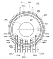
- FIG. 2 is a schematic configuration diagram of part of a vertical processing furnace of a substrate processing apparatus suitably used in one aspect of the present disclosure, and is a diagram showing the processing furnace 202 portion along the AA line cross-sectional view of FIG. be.
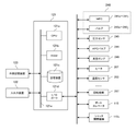
- FIG. 3 is a schematic configuration diagram of the controller 121 of the substrate processing apparatus preferably used in one aspect of the present disclosure, and is a block diagram showing the control system of the controller 121.
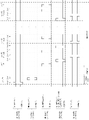
- FIG. 5 is a flow diagram illustrating a processing sequence in accordance with one aspect of the present disclosure
- FIG. 4 is a diagram illustrating a processing sequence of one aspect of the present disclosure.
- FIG. 6 is a plan view showing part of a substrate used in one aspect of the present disclosure;
- FIG. 1 One aspect of the present disclosure will be described below with reference to FIGS. 1 to 6.
- FIG. 1 The drawings used in the following description are all schematic, and the dimensional relationship of each element, the ratio of each element, etc. shown in the drawings do not necessarily match the actual ones. Moreover, the dimensional relationship of each element, the ratio of each element, etc. do not necessarily match between a plurality of drawings.
- the processing furnace 202 has a heater 207 as a temperature controller (heating unit).
- the heater 207 has a cylindrical shape and is installed vertically by being supported by a holding plate.
- the heater 207 also functions as an activation mechanism (excitation section) that thermally activates (excites) the gas.
- a reaction tube 203 is arranged concentrically with the heater 207 inside the heater 207 .
- the reaction tube 203 is made of a heat-resistant material such as quartz (SiO 2 ) or silicon carbide (SiC), and has a cylindrical shape with a closed upper end and an open lower end.
- a manifold 209 is arranged concentrically with the reaction tube 203 below the reaction tube 203 .
- the manifold 209 is made of a metal material such as stainless steel (SUS), and is formed in a cylindrical shape with open upper and lower ends. The upper end of the manifold 209 engages the lower end of the reaction tube 203 and is configured to support the reaction tube 203 .
- An O-ring 220a is provided between the manifold 209 and the reaction tube 203 as a sealing member.
- Reactor tube 203 is mounted vertically like heater 207 .
- a processing vessel (reaction vessel) is mainly configured by the reaction tube 203 and the manifold 209 .
- a processing chamber 201 is formed in the cylindrical hollow portion of the processing container. The processing chamber 201 is configured to accommodate a wafer 200 as a substrate. A wafer 200 is processed in the processing chamber 201 .
- nozzles 249a to 249e as first to fifth supply units are provided so as to penetrate the side wall of the manifold 209, respectively.
- Gas supply pipes 232a to 232e are connected to the nozzles 249a to 249e, respectively.
- the nozzles 249a to 249e are different nozzles, and each of the nozzles 249b and 249d is provided adjacent to the nozzle 249c.
- Each of the nozzles 249a and 249e is provided adjacent to the side opposite to the side adjacent to the nozzle 249c of the nozzle 249b and the nozzle 249d.
- the gas supply pipes 232a to 232e are provided with mass flow controllers (MFC) 241a to 241e as flow rate controllers (flow control units) and valves 243a to 243e as opening/closing valves, respectively, in this order from the upstream side of the gas flow. .
- Gas supply pipes 232f to 232j are connected to the gas supply pipes 232a to 232e downstream of the valves 243a to 243e, respectively.
- the gas supply pipes 232f to 232j are provided with MFCs 241f to 241j and valves 243f to 243j, respectively, in this order from the upstream side of the gas flow.
- the gas supply pipes 232a to 232e are made of metal material such as SUS, for example.
- the nozzles 249a to 249e are arranged in an annular space between the inner wall of the reaction tube 203 and the wafer 200 in a plan view, along the inner wall of the reaction tube 203 from the bottom to the top. They are provided so as to rise upward in the arrangement direction. That is, the nozzles 249a to 249e are provided on the sides of the wafer arrangement area in which the wafers 200 are arranged, in the area horizontally surrounding the wafer arrangement area, along the wafer arrangement area. In a plan view, the nozzle 249c is arranged so as to face an exhaust port 231a, which will be described later, on a straight line with the center of the wafer 200 carried into the processing chamber 201 interposed therebetween.
- the nozzles 249b and 249d are arranged along the inner wall of the reaction tube 203 (peripheral portion of the wafer 200) to sandwich a straight line L passing through the nozzle 249c and the center of the exhaust port 231a from both sides. Further, the nozzles 249a and 249e are arranged so as to sandwich the straight line L from both sides along the inner wall of the reaction tube 203 on the opposite side of the nozzles 249b and 249d adjacent to 249c.
- the straight line L is also a straight line passing through the nozzle 249 c and the center of the wafer 200 . That is, it can be said that the nozzle 249d is provided on the opposite side of the straight line L from the nozzle 249b.
- the nozzle 249e is provided on the opposite side of the straight line L from the nozzle 249a.
- the nozzles 249b and 249d are arranged line-symmetrically with the straight line L as the axis of symmetry.
- the nozzles 249a and 249e are arranged line-symmetrically with the straight line L as the axis of symmetry.
- Gas supply holes 250a to 250e for supplying gas are provided on the side surfaces of the nozzles 249a to 249e, respectively.
- Each of the gas supply holes 250a to 250e is open to face the exhaust port 231a in a plan view, and is capable of supplying gas toward the wafer 200.
- a plurality of gas supply holes 250 a to 250 e are provided from the bottom to the top of the reaction tube 203 .
- a Group 14 element-containing gas is supplied as a processing gas from the gas supply pipe 232a into the processing chamber 201 via the MFC 241a, the valve 243a, and the nozzle 249a.
- a dopant gas containing a halide of a group 13 element or a group 15 element is supplied from the gas supply pipe 232b into the processing chamber 201 via the MFC 241b, the valve 243b, and the nozzle 249b.
- a first reducing gas is supplied as a reducing gas from the gas supply pipe 232c into the processing chamber 201 via the MFC 241c, the valve 243c, and the nozzle 249c.
- a first halosilane-based gas is supplied as a processing gas from the gas supply pipe 232d into the processing chamber 201 via the MFC 241d, the valve 243d, and the nozzle 249d.
- a second halosilane-based gas is supplied as a processing gas from the gas supply pipe 232e into the processing chamber 201 via the MFC 241e, the valve 243e, and the nozzle 249e.
- inert gas is supplied into processing chamber 201 through MFCs 241f to 241j, valves 243f to 243j, gas supply pipes 232a to 232e, and nozzles 249a to 249e, respectively.
- Inert gases act as purge gas, carrier gas, diluent gas, and the like.
- a processing gas supply system is mainly composed of gas supply pipes 232a, 232d, 232e, MFCs 241a, 241d, 241e, and valves 243a, 243d, 243e.
- the gas supply pipe 232b, the MFC 241b, and the valve 243b may be included in the processing gas supply system.
- a reducing gas supply system is mainly composed of the gas supply pipe 232c, the MFC 241c, and the valve 243c.
- An inert gas supply system is mainly composed of gas supply pipes 232f to 232j, MFCs 241f to 241j, and valves 243f to 243j.
- the gas supply system including the gas supply pipe 232a, the MFC 241a, and the valve 243a is also referred to as a first supply system.
- the gas supply pipe 232f, MFC 241f, and valve 243f may be included in the first supply system.
- a gas supply system including the gas supply pipe 232b, the MFC 241b, and the valve 243b is also called a second supply system.
- the gas supply pipe 232g, MFC 241g, and valve 243g may be included in the second supply system.
- a gas supply system including the gas supply pipe 232c, the MFC 241c, and the valve 243c is also called a third supply system.
- the gas supply pipe 232h, MFC 241h, and valve 243h may be included in the third supply system.
- a gas supply system including the gas supply pipe 232d, the MFC 241d, and the valve 243d is also called a third supply system.
- the gas supply pipe 232i, MFC 241i, and valve 243i may be included in the third supply system.
- a gas supply system including the gas supply pipe 232e, the MFC 241e, and the valve 243e is also called a third supply system.
- the gas supply pipe 232j, MFC 241j, and valve 243j may be included in the third supply system.
- any or all of the various supply systems described above may be configured as an integrated supply system 248 in which valves 243a to 243j, MFCs 241a to 241j, etc. are integrated.
- the integrated supply system 248 is connected to each of the gas supply pipes 232a to 232j, and supplies various gases into the gas supply pipes 232a to 232j, that is, the opening and closing operations of the valves 243a to 243j and the MFCs 241a to 241j.
- the flow rate adjustment operation and the like are configured to be controlled by a controller 121, which will be described later.
- the integrated supply system 248 is configured as an integral or divided integrated unit, and can be attached/detached to/from the gas supply pipes 232a to 232j and the like in units of integrated units. It is configured so that maintenance, replacement, expansion, etc. can be performed on an integrated unit basis.
- An exhaust port 231 a for exhausting the atmosphere in the processing chamber 201 is provided below the side wall of the reaction tube 203 . As shown in FIG. 2, the exhaust port 231a is provided at a position facing the nozzles 249a to 249e (gas supply holes 250a to 250e) across the wafer 200 in plan view. The exhaust port 231a may be provided along the upper portion of the side wall of the reaction tube 203, that is, along the wafer arrangement area.
- An exhaust pipe 231 is connected to the exhaust port 231a.
- the exhaust pipe 231 is supplied with a pressure sensor 245 as a pressure detector (pressure detector) for detecting the pressure in the processing chamber 201 and an APC (Auto Pressure Controller) valve 244 as a pressure regulator (pressure regulator).
- a vacuum pump 246 as an evacuation device is connected.
- the inside of the processing chamber 201 can be evacuated and stopped.
- the pressure in the processing chamber 201 can be adjusted.
- An exhaust system is mainly composed of the exhaust pipe 231 , the APC valve 244 and the pressure sensor 245 .
- a vacuum pump 246 may be considered to be included in the exhaust system.
- a seal cap 219 is provided below the manifold 209 as a furnace mouth cover capable of airtightly closing the lower end opening of the manifold 209 .
- the seal cap 219 is made of, for example, a metal material such as SUS, and is shaped like a disc.
- An O-ring 220 b is provided on the upper surface of the seal cap 219 as a sealing member that contacts the lower end of the manifold 209 .
- a rotating mechanism 267 for rotating the boat 217 which will be described later, is installed below the seal cap 219.
- a rotating shaft 255 of the rotating mechanism 267 passes through the seal cap 219 and is connected to the boat 217 .
- the rotating mechanism 267 is configured to rotate the wafers 200 by rotating the boat 217 .
- the seal cap 219 is vertically moved up and down by a boat elevator 115 as a lifting mechanism installed outside the reaction tube 203 .
- the boat elevator 115 is configured as a transport device (transport mechanism) for loading and unloading (transporting) the wafer 200 into and out of the processing chamber 201 by raising and lowering the seal cap 219 .
- a shutter 219s is provided as a furnace port cover that can airtightly close the lower end opening of the manifold 209 in a state in which the seal cap 219 is lowered and the boat 217 is carried out of the processing chamber 201.
- the shutter 219s is made of a metal material such as SUS, and is shaped like a disc.
- An O-ring 220c is provided on the upper surface of the shutter 219s as a sealing member that contacts the lower end of the manifold 209. As shown in FIG.
- the opening/closing operation (elevating operation, rotating operation, etc.) of the shutter 219s is controlled by the shutter opening/closing mechanism 115s.
- the boat 217 as a substrate support supports a plurality of wafers 200, for example, 25 to 200 wafers 200, in a horizontal posture, aligned vertically with their centers aligned with each other, and supported in multiple stages. It is configured to be spaced and arranged.
- the boat 217 is made of a heat-resistant material such as quartz or SiC.
- a plurality of heat insulating plates 218 made of a heat-resistant material such as quartz or SiC are supported.
- a temperature sensor 263 as a temperature detector is installed in the reaction tube 203 .
- the temperature inside the processing chamber 201 has a desired temperature distribution.
- a temperature sensor 263 is provided along the inner wall of the reaction tube 203 .
- the controller 121 which is a control unit (control means), is configured as a computer comprising a CPU (Central Processing Unit) 121a, a RAM (Random Access Memory) 121b, a storage device 121c, and an I/O port 121d. It is The RAM 121b, storage device 121c, and I/O port 121d are configured to exchange data with the CPU 121a via an internal bus 121e.
- An input/output device 122 configured as, for example, a touch panel or the like is connected to the controller 121 .
- the storage device 121c is composed of, for example, flash memory, HDD (Hard Disk Drive), SSD (Solid State Drive), and the like.
- a control program for controlling the operation of the substrate processing apparatus, a process recipe describing procedures and conditions for substrate processing, which will be described later, and the like are stored in a readable manner.
- the process recipe functions as a program in which the controller 121 executes each procedure in substrate processing, which will be described later, and is combined so as to obtain a predetermined result.
- process recipes, control programs, and the like are collectively referred to simply as programs.
- a process recipe is also simply referred to as a recipe.
- the term program is used in the present disclosure, it may include only recipes alone, may include only control programs alone, or may include both.
- the RAM 121b is configured as a memory area (work area) in which programs and data read by the CPU 121a are temporarily held.
- the I/O port 121d includes the MFCs 241a to 241j, valves 243a to 243j, pressure sensor 245, APC valve 244, vacuum pump 246, temperature sensor 263, heater 207, rotating mechanism 267, boat elevator 115, shutter opening/closing mechanism 115s, and the like. It is connected to the.
- the CPU 121a is configured to read and execute a control program from the storage device 121c, and to read recipes from the storage device 121c in response to input of operation commands from the input/output device 122 and the like.
- the CPU 121a adjusts the flow rate of various gases by the MFCs 241a to 241g, the opening and closing operations of the valves 243a to 243g, the opening and closing operations of the APC valve 244, and the pressure adjustment by the APC valve 244 based on the pressure sensor 245 so as to follow the content of the read recipe.
- shutter opening/closing mechanism 115s is configured to be able to control the opening/closing operation of the shutter 219s and the like.
- the controller 121 can be configured by installing the above-described program stored in the external storage device 123 in the computer.
- the external storage device 123 includes, for example, a magnetic disk such as an HDD, an optical disk such as a CD, a magneto-optical disk such as an MO, a USB memory, a semiconductor memory such as an SSD, and the like.
- the storage device 121c and the external storage device 123 are configured as computer-readable recording media. Hereinafter, these are also collectively referred to simply as recording media.
- recording medium may include only the storage device 121c alone, may include only the external storage device 123 alone, or may include both of them.
- the program may be provided to the computer using communication means such as the Internet or a dedicated line without using the external storage device 123 .
- step F of supplying the Group 14 element-containing gas to the wafer 200 is performed after step E.
- a step of forming a film containing a group 14 element as a main element to which a group 13 element or a group 15 element is added (doped) on the wafer 200 is performed.
- a film containing a group 14 element as a main element doped with a group 13 element or a group 15 element is also referred to as a doped film.
- step F of supplying a Group 14 element-containing gas as a processing gas to the wafer 200 from the nozzle 249a is performed.
- step G of supplying two types of halosilane-based gases to wafer 200 is performed before step A.
- step G of supplying two types of halosilane-based gases to wafer 200 is performed before step A.
- step G of supplying two types of halosilane-based gases to wafer 200 is performed before step A.
- a step of forming a seed layer is performed on the wafer 200 .
- step G1 of supplying a first halosilane-based gas from the nozzle 249d to the wafer 200; After step 1, step G2 of supplying a second halosilane-based gas different from the first halosilane-based gas to the wafer 200 from the nozzle 249e is performed.
- wafer When the term “wafer” is used in the present disclosure, it may mean the wafer itself, or it may mean a laminate of the wafer and predetermined layers or films formed on its surface.
- wafer surface When the term “wafer surface” is used in the present disclosure, it may mean the surface of the wafer itself or the surface of a predetermined layer or the like formed on the wafer.
- a predetermined layer is formed on a wafer
- it means that a predetermined layer is directly formed on the surface of the wafer itself, or a layer formed on the wafer, etc. It may mean forming a given layer on top.
- substrate in this disclosure is synonymous with the use of the term "wafer.”
- the inside of the processing chamber 201 that is, the space in which the wafer 200 exists is evacuated (reduced pressure) by the vacuum pump 246 so that it has a desired pressure (degree of vacuum).
- the pressure in the processing chamber 201 is measured by the pressure sensor 245, and the APC valve 244 is feedback-controlled based on the measured pressure information.
- the wafer 200 in the processing chamber 201 is heated by the heater 207 so as to reach a desired film formation temperature.
- the energization state of the heater 207 is feedback-controlled based on the temperature information detected by the temperature sensor 263 so that the inside of the processing chamber 201 has a desired temperature distribution.
- the rotation of the wafer 200 by the rotation mechanism 267 is started. The evacuation of the processing chamber 201 and the heating and rotation of the wafer 200 continue at least until the processing of the wafer 200 is completed.
- a step G1 of supplying a first halosilane-based gas and a step G2 of supplying a second halosilane-based gas different from the first halosilane-based gas are sequentially performed.
- Step G1 the first halosilane-based gas is supplied from the nozzle 249d to the wafer 200 in the processing chamber 201, and the inert gas is supplied from each of the nozzles 249a to 249c and 249e.
- valve 243d is opened to allow the first halosilane-based gas to flow into the gas supply pipe 232d.
- the flow rate of the first halosilane-based gas is adjusted by the MFC 241d, supplied into the processing chamber 201 through the nozzle 249d, and exhausted through the exhaust port 231a.
- the first halosilane-based gas is supplied to the wafer 200 .
- the valves 243f to 243h and 243j are opened to supply the inert gas into the processing chamber 201 through the nozzles 249a to 249c and 249e, respectively.
- the natural oxide film, impurities, etc. are removed from the surface of the wafer 200 by the treatment action (etching action) of the first halosilane-based gas. It is possible to clean this surface.
- the valve 243d is closed and the supply of the halosilane-based gas into the processing chamber 201 is stopped. Then, the inside of the processing chamber 201 is evacuated, and gas and the like remaining in the processing chamber 201 are removed from the inside of the processing chamber 201 . At this time, the valves 243f to 243j are opened to supply the inert gas into the processing chamber 201 through the nozzles 249a to 249e. The inert gas supplied from the nozzles 249a to 249e acts as a purge gas, thereby purging the inside of the processing chamber 201 (purge step).
- Examples of the first halosilane-based gas include dichlorosilane (SiH 2 Cl 2 , abbreviation: DCS) gas, monochlorosilane (SiH 3 Cl, abbreviation: MCS) gas, tetrachlorosilane (SiCl 4 , abbreviation: STC) gas, and trichlorosilane (SiCl 4 , abbreviation: STC) gas.
- DCS dichlorosilane
- MCS monochlorosilane
- STC tetrachlorosilane
- STC trichlorosilane
- Chlorosilane-based gases such as chlorosilane (SiHCl 3 , abbreviation: TCS) gas, hexachlorodisilane (Si 2 Cl 6 , abbreviation: HCDS) gas, and octachlorotrisilane (Si 3 Cl 8 , abbreviation: OCTS) gas can be used.
- TCS chlorosilane
- HCDS hexachlorodisilane
- OCTS octachlorotrisilane
- the first halosilane-based gas for example, tetrafluorosilane (SiF 4 ) gas, tetrabromosilane (SiBr 4 ) gas, tetraiodosilane (SiI 4 ) gas, or the like can be used.
- a halosilane-based gas for example, in addition to the chlorosilane-based gas, a halosilane-based gas such as a fluorosilane-based gas, a bromosilane-based gas, and an iodosilane-based gas can be used.
- Step G2 After step G1 is completed, the second halosilane-based gas is supplied from the nozzle 249e to the wafer 200 in the processing chamber 201, that is, the cleaned surface of the wafer 200, and is inerted from each of the nozzles 249a to 249d. Supply gas.
- valve 243e is opened to allow the second halosilane-based gas to flow into the gas supply pipe 232e.
- the flow rate of the second halosilane-based gas is adjusted by the MFC 241e, supplied into the processing chamber 201 through the nozzle 249e, and exhausted through the exhaust port 231a.
- the second halosilane-based gas is supplied to the wafer 200 .
- the valves 243f to 243i are opened to supply the inert gas into the processing chamber 201 through the nozzles 249a to 249d, respectively.
- the Si element contained in the second halosilane-based gas is adsorbed on the surface of the wafers 200 cleaned in step G1, thereby forming a seed. (Nucleus) can be formed. Under the processing conditions described later, the crystal structure of the nuclei formed on the surface of the wafer 200 becomes amorphous.
- the valve 243e is closed and the supply of the second halosilane-based gas into the processing chamber 201 is stopped. Then, the gas remaining in the processing chamber 201 is removed from the processing chamber 201 by the same processing procedure as the purge step of step G1.
- the halosilane-based gas described above for the first halosilane-based gas can be used.
- First halosilane-based gas supply flow rate 100 to 1000 sccm
- First halosilane-based gas supply time 1 to 30 minutes
- Processing pressure: 2 to 1000 Pa are exemplified.
- First halosilane-based gas or second reducing gas supply flow rate 50 to 1000 sccm
- First halosilane-based gas or second reducing gas supply time 10 seconds to 5 minutes are exemplified.
- Other processing conditions are the same as the processing conditions in step G1.
- the notation of a numerical range such as “2 to 1000 Pa” in the present disclosure means that the lower limit and upper limit are included in the range. Therefore, for example, “2 to 1000 Pa” means “2 Pa or more and 1000 Pa or less”.
- the processing temperature means the temperature of the wafer 200
- the processing pressure means the pressure inside the processing chamber 201 .
- the gas supply flow rate: 0 sccm means a case where the gas is not supplied.
- the inert gas for example, rare gases such as N2 gas, Ar gas, He gas, Ne gas, and Xe gas can be used. This point also applies to the temperature raising step, the film forming step, and the like, which will be described later.
- the output of the heater 207 is adjusted so as to change the temperature inside the processing chamber 201 to a second temperature higher than the first temperature.
- the valves 243f to 243j are opened to supply an inert gas into the processing chamber 201 through the nozzles 249a to 249e to purge the inside of the processing chamber 201.
- FIG. After the temperature inside the processing chamber 201 reaches the second temperature and becomes stable, a film forming step, which will be described later, is started.
- step A of supplying a Group 14 element-containing gas As a film formation step, a step A of supplying a Group 14 element-containing gas; Step B of supplying a dopant gas containing a halide of a group 13 element or a group 15 element, step C of supplying a first reducing gas, and step D of supplying a group 14 element-containing gas are performed in this manner.
- a step E of performing a cycle including in order a predetermined number of times after step A; are executed sequentially. Furthermore, after step E, step F of supplying the Group 14 element-containing gas is performed.
- Step A the Group 14 element-containing gas is supplied from the nozzle 249a to the wafer 200 in the processing chamber 201, that is, the surface of the seed layer formed on the wafer 200, and the undesired gas is supplied from the nozzles 249b to 249e. Supply active gas.
- valve 243a is opened to allow the Group 14 element-containing gas to flow into the gas supply pipe 232a.
- the group 14 element-containing gas is adjusted in flow rate by the MFC 241a, supplied into the processing chamber 201 through the nozzle 249a, and exhausted through the exhaust port 231a.
- the valves 243g to 243j are opened to supply the inert gas into the processing chamber 201 through the nozzles 249b to 249e, respectively.
- the group 14 element is deposited on the surface of the wafer 200, that is, on the seed layer formed on the wafer 200. can be formed as a main element.
- Group 14 element-containing gas supply flow rate 100 to 3000 sccm
- Group 14 element-containing gas supply time 1 to 30 minutes
- Processing pressure 1 to 1000 Pa
- the processing conditions shown here are the conditions under which the Group 14 element-containing gas thermally decomposes when the Group 14 element-containing gas exists alone in the processing chamber 201, that is, the conditions under which the CVD reaction occurs.
- the processing conditions shown here are conditions under which the adsorption (deposition) of the Group 14 element onto the wafer 200 is not self-limited, that is, the adsorption of the Group 14 element onto the wafer 200 is non-self-limited. It is a condition.
- Group 14 element-containing gases examples include monosilane (SiH 4 , abbreviation: MS) gas, disilane (Si 2 H 6 , abbreviation: DS) gas, trisilane (Si 3 H 8 ) gas, and tetrasilane (Si 4 H 10 ) gas.
- germane hydride gas such as hexasilane (Si 6 H 14 ) gas, germane (GeH 4 ) gas, digermane (Ge 2 H 6 ) gas, trigermane (Ge 3 H 8 ) gas, tetragermane (Ge 4 H 10 ) gas, pentagermane (Ge 5 H 12 ) gas, hexagermane (Ge 6 H 14 ) gas, and other germanium hydride gases can be used.
- Group 14 element-containing gases include monosilane (SiH 4 , abbreviation: MS) gas, disilane (Si 2 H 6 , abbreviation: DS) gas, trisilane (Si 3 H 8 ) gas, and germane (GeH 4 ) gas. , digermane (Ge 2 H 6 ) gas, or trigermane (Ge 3 H 8 ) gas. Since these react (decompose) relatively easily, the film formation rate can be improved.
- step E a cycle including steps B, C, and D below in this order is performed a predetermined number of times (n times, where n is an integer of 2 or more).
- n times an integer of 2 or more
- a film doped with a group 13 element or a group 15 element and containing a group 14 element as a main element and having a small surface roughness can be formed on the wafer 200 .
- Step B After step A is completed, the wafer 200 in the processing chamber 201, that is, the surface of the film containing the group 14 element as the main element formed on the wafer 200 is subjected to the group 13 element or the group 13 element from the nozzle 249b.
- a dopant gas containing a halide of a Group 15 element is supplied, and an inert gas is supplied from each of nozzles 249a, 249c to 249e.
- valve 243b is opened to allow the dopant gas to flow into the gas supply pipe 232b.
- the dopant gas is adjusted in flow rate by the MFC 241b, supplied into the processing chamber 201 through the nozzle 249b, and exhausted through the exhaust port 231a.
- the valves 243f, 243h to 243j are opened to supply the inert gas into the processing chamber 201 through the nozzles 249a, 249c to 249e, respectively.
- a group 13 element or a group 15 A film containing a halide of a group element as a main component can be formed.
- a dopant gas containing a halide of a Group 13 element a gas containing an element (boron (B), etc.) that is a Group 13 element and becomes a solid by itself, such as trichloroborane (BCl 3 ) gas.
- a dopant gas containing the halide of the Group 15 element for example, an element (P, arsenic ( As) etc.) can be used.
- one containing B element is preferable.
- a gas containing BCl 3 film formation can be easily performed even when the surface of the wafer 200 has a fine structure.
- a gas containing Cl element in addition to B element is preferable.
- the Cl element of BCl 3 adsorbed on the film containing the Group 14 element as the main element inhibits the adsorption of the Group 14 element-containing gas on the film, but is easily reduced in step C to remove the Cl element. Detach. Therefore, in steps D and F, adsorption of the Group 14 element-containing gas to the film is promoted, and the film formation speed can be improved.
- Step C After step B is completed, the nozzle A first reducing gas is supplied from 249c, and an inert gas is supplied from each of nozzles 249a, 249b, 249d, and 249e.
- valve 243c is opened to allow the first reducing gas to flow into the gas supply pipe 232c.
- the flow rate of the first reducing gas is adjusted by the MFC 241c, supplied into the processing chamber 201 through the nozzle 249c, and exhausted through the exhaust port 231a.
- the valves 243f, 243g, 243i and 243j are opened to supply the inert gas into the processing chamber 201 through the nozzles 249a, 249b, 249d and 249e, respectively.
- the group 13 element or the group 15 element formed on the surface of the wafer 200 is removed.
- a halogen element in a film containing a halide as a main component can be removed by reduction. This makes it possible to form a film containing a group 13 element or a group 15 element as a main element.
- a hydrogen-based gas such as hydrogen (H 2 ) gas, hydrogen-containing gas, or activated hydrogen gas
- Activated hydrogen gas includes, for example, plasma-activated gas.
- a hydrogen-containing gas is preferably used as the first reducing gas.
- the halogen element that inhibits the adsorption of the Group 14 element-containing gas to the film is easily reduced and desorbed. Therefore, in steps D and F, adsorption of the group 14 element to the film is promoted, and the film formation speed can be improved.
- Step D After step C is completed, the wafer 200 in the processing chamber 201, that is, the surface of the film formed on the wafer 200 and containing the group 13 element or the group 15 element as the main element is subjected to the first A Group 14 element-containing gas is supplied, and an inert gas is supplied from each of the nozzles 249b to 249e.
- valve 243a is opened to allow the Group 14 element-containing gas to flow into the gas supply pipe 232a.
- the group 14 element-containing gas is adjusted in flow rate by the MFC 241a, supplied into the processing chamber 201 through the nozzle 249a, and exhausted through the exhaust port 231a.
- the valves 243g to 243j are opened to supply the inert gas into the processing chamber 201 through the nozzles 249b to 249e, respectively.
- the group 13 element or group 15 element formed on the surface of the wafer 200 that is, on the wafer 200
- a film containing a group 14 element as a main element can be formed on a film containing an element as a main element.
- the gas described above for step A can be used.
- step B Dopant gas supply flow rate: 10 to 400 sccm Dopant gas supply time: 1 to 30 minutes Inert gas supply flow rate (per gas supply pipe): 300 to 5000 sccm Processing temperature (second temperature): 350-550°C Processing pressure: 0.1 to 1000 Pa are exemplified.
- First reducing gas supply flow rate 10 to 3000 sccm
- First reducing gas supply time 1 to 30 minutes is exemplified.
- Other processing conditions are the same processing conditions as the processing conditions in step B.
- step D Group 14 element-containing gas supply flow rate: 10 to 3000 sccm
- Group 14 element-containing gas supply time 0.1 to 30 minutes is exemplified.
- Other processing conditions are the same processing conditions as the processing conditions in step B. FIG.
- Step F After step E is completed, the Group 14 element-containing gas is applied from the nozzle 249 a to the wafer 200 in the processing chamber 201 , that is, the surface of the film containing the Group 14 element as the main element formed on the wafer 200 . is supplied, and an inert gas is supplied from each of the nozzles 249b to 249e.
- valve 243a is opened to allow the Group 14 element-containing gas to flow into the gas supply pipe 232a.
- the group 14 element-containing gas is adjusted in flow rate by the MFC 241a, supplied into the processing chamber 201 through the nozzle 249a, and exhausted through the exhaust port 231a.
- the valves 243g to 243j are opened to supply the inert gas into the processing chamber 201 through the nozzles 249b to 249e, respectively.
- the group 14 element formed on the surface of the wafer 200 that is, the wafer 200 as a main element
- a film containing a Group 14 element as a main element can be further formed on the containing film.
- the gas described above for step A can be used.
- step F Group 14 element-containing gas supply flow rate: 10 to 5000 sccm
- Group 14 element-containing gas supply time 1 to 30 minutes
- Processing pressure 0.1 to 1000 Pa
- Other processing conditions are the same processing conditions as the processing conditions in step B.
- N 2 gas as a purge gas is supplied into the processing chamber 201 from each of the nozzles 249a to 249c and exhausted from the exhaust port 231a.
- the inside of the processing chamber 201 is purged, and gas remaining in the processing chamber 201 and reaction by-products are removed from the inside of the processing chamber 201 (afterpurge).
- the atmosphere in the processing chamber 201 is replaced with an inert gas (inert gas replacement), and the pressure in the processing chamber 201 is returned to normal pressure (atmospheric pressure recovery).
- the seal cap 219 is lowered by the boat elevator 115, and the lower end of the manifold 209 is opened. Then, the processed wafer 200 is unloaded from the reaction tube 203 from the lower end of the manifold 209 while being supported by the boat 217 (boat unloading). After the boat is unloaded, the shutter 219s is moved and the lower end opening of the manifold 209 is sealed by the shutter 219s via the O-ring 220c (shutter closed). The processed wafers 200 are carried out of the reaction tube 203 and then taken out from the boat 217 (wafer discharge).
- step A a film containing a group 14 element as a main element is formed on the seed layer.
- step B a film containing a halide of a group 13 element or a group 15 element as a main component is formed in step B, an increase in surface roughness can be suppressed.
- step C the halogen element of the film containing the group 13 element or group 15 element halide as a main component is reduced and removed to form a film containing the group 13 element or group 15 element as a main element; can be formed. Therefore, in step D, it is possible to prevent the adsorption of the Group 14 element-containing gas on the film from being inhibited by the halogen element.
- step D By providing a film containing a group 14 element as a main element as a cap layer on the film containing a group 13 element or a group 15 element as a main element in step D, the dopant from the film (i.e., 13th group element or 15th group element) can be suppressed.
- step D a film containing a group 14 element as a main element is provided as a cap layer on the film containing a group 13 element or a group 15 element as a main element, thereby removing dopants from the film. It is possible to suppress an increase in surface roughness due to removal.
- step E A surface doped with a group 13 element or a group 15 element and containing a group 14 element as a main element by step E in which a cycle including such steps B to D in this order is performed a predetermined number of times A film with low roughness can be formed.
- step F In the film formation step, by further performing step F, the Cap layer of the film on the wafer 200 can be thickened, and the escape of dopants from the film can be further suppressed.
- the surface roughness of the film formed on the wafer 200 can be reduced by forming the seed layer.
- the film forming step in this embodiment is not limited to the embodiments shown in FIGS. 4 and 5, and can be modified as in the following modifications. These modifications can be combined arbitrarily. Unless otherwise specified, the processing procedures and processing conditions in each step of each modification can be the same as the processing procedures and processing conditions in each step of the substrate processing sequence described above.
- step C (Modification 2)
- step C the step of supplying the first reducing gas
- step B a dopant containing a halide of the 13th element or the 15th group element was used, but a non-halogen compound of the 13th element or the 15th group element, , hydride-containing dopants may be used.
- the dopant gas containing the hydride of the 13th element an element that is a group 13 element such as borane (BH 3 ), diborane (B 2 H 6 ) gas, etc. and is solid by itself (boron (B), etc.) ) can be used.
- the dopant gas containing a hydride of a Group 15 element an element that is a Group 15 element that is solid by itself, such as phosphine (PH 3 , abbreviation: PH) gas, arsine (AsH 3 ) gas, etc.
- PH phosphine
- a gas containing (P, arsenic (As), etc.) can be used.
- N nitrogen
- the group 14 element-containing gas supply time in step D may be set longer than the group 14 element-containing gas supply time in step A.
- the cap layer formed in step E can be thickened while the film formation time in step A is shortened, thereby suppressing dopant removal from the film on the wafer 200 .
- the Group 14 element-containing gas supply time in Step D may be set longer than the Group 14 element-containing gas supply time in Step A. As a result, all the films formed in step D can be thickened, so that dopant removal from the films on the wafer 200 can be further suppressed.
- the Group 14 element-containing gas supply time in step D may be, for example, 1 to 10 times the Group 14 element-containing gas supply time in step A.
- step G2 is performed in step G has been described, but step G2 may not be performed.
- step G2 (Modification 8)
- the second reducing gas may be supplied instead of the second halosilane-based gas.
- step G2 may be performed in the same procedure as in the case of using the second halosilane-based gas.
- Examples of the second reducing gas include hydrogen (H 2 ) gas, monosilane (SiH 4 , abbreviation: MS) gas, disilane (Si 2 H 6 , abbreviation: DS) gas, trisilane (Si 3 H 8 ) gas, and tetrasilane.
- Silicon hydride gas such as (Si 4 H 10 ) gas, pentasilane (Si 5 H 12 ) gas, hexasilane (Si 6 H 14 ) gas can be used.
- the second reducing gas one containing Si element may be used. By using the second reducing gas, the surface roughness of the film formed on the wafer 200 can be reduced.
- the surface of the wafer 200 cleaned in step G1 can adsorb Si contained in the second reducing gas to form seeds (nuclei). Further, the H element contained in the second reducing gas can reduce and remove the halogen element derived from the first halosilane gas on the surface of the wafer 200 cleaned in step G1. Thereby, the surface roughness of the film formed on the wafer 200 can be reduced.
- a film may be formed on the wafer 200 by, for example, the following film formation sequence.
- a seed layer may be formed on the wafer 200 by, for example, the following film formation sequence.
- the wafer 200 as a substrate may have a microstructure by performing microfabrication on the surface in advance.
- the surface of the wafer 200 may be formed with a first recess D1 extending in a direction perpendicular to the surface of the wafer 200 .
- a plurality of second recesses D2 may be formed which are perpendicular to the longitudinal direction of the first recesses D1 and extend in the in-plane direction of the wafer 200.
- the first recess D1 means a trench or hole
- the second recess D2 means a space in which a floating gate is formed in the trench or hole.
- films are formed in the first recess D1 and the second recess D2.
- the film formation step of the present disclosure allows formation of a film with low surface roughness even when the wafer 200 has a fine structure. That is, it becomes possible to form a film uniformly in the first recess D1 and the second recess D2.
- the nozzles 249a to 249e are provided adjacent (adjacent)
- the present disclosure is not limited to such an aspect.
- the nozzles 249a, 249b, 249d, and 249c may be provided at positions away from the nozzle 249c in the annular space between the inner wall of the reaction tube 203 and the wafer 200 in plan view.
- the present disclosure is not limited to such an aspect.
- at least one of the first to fifth supply units may be composed of two or more nozzles.
- a nozzle other than the first to fifth supply units may be newly provided in the processing chamber 201, and the inert gas and various processing gases may be further supplied using this nozzle.
- the newly provided nozzles may or may not be provided at positions facing the exhaust port 231a in plan view.
- the newly provided nozzles are positioned away from the nozzles 249a to 249e, for example, along the outer periphery of the wafer 200 in the annular space in plan view between the inner wall of the reaction tube 203 and the wafer 200. It may be provided at an intermediate position between the nozzles 249a to 249e and the exhaust port 231a, or at a position near the intermediate position.
- Recipes used for substrate processing are preferably prepared individually according to the processing content and stored in the storage device 121c via an electric communication line or the external storage device 123. Then, when starting the processing, it is preferable that the CPU 121a appropriately selects an appropriate recipe from among the plurality of recipes stored in the storage device 121c according to the content of the substrate processing.
- a single substrate processing apparatus can form films having various film types, composition ratios, film qualities, and film thicknesses with good reproducibility.
- the burden on the operator can be reduced, and the processing can be started quickly while avoiding operational errors.
- the recipes described above are not limited to the case of newly creating them, and for example, they may be prepared by modifying existing recipes that have already been installed in the substrate processing apparatus.
- the changed recipe may be installed in the substrate processing apparatus via an electric communication line or a recording medium recording the recipe.
- an existing recipe already installed in the substrate processing apparatus may be directly changed by operating the input/output device 122 provided in the existing substrate processing apparatus.
- an example of forming a film using a batch-type substrate processing apparatus that processes a plurality of substrates at once has been described.
- the present disclosure is not limited to the embodiments described above, and can be suitably applied, for example, to the case of forming a film using a single substrate processing apparatus that processes one or several substrates at a time.
- an example of forming a film using a substrate processing apparatus having a hot wall type processing furnace has been described.
- the present disclosure is not limited to the above embodiments, and can be suitably applied to the case of forming a film using a substrate processing apparatus having a cold wall type processing furnace.
- processing procedure and processing conditions at this time can be, for example, the same as the processing procedures and processing conditions of the above-described mode.
- the various effects described in the present disclosure can be obtained not only under conditions in which the process gas supplied to the substrate thermally decomposes (conditions under which self-limiting is not applied), but also under conditions in which the film is formed on the substrate. A similar tendency is obtained even under conditions in which the treated gas does not thermally decompose (under self-limiting conditions).
- the effect related to the adjustment of the in-plane film thickness distribution in particular, is that the film formation on the substrate is performed under the conditions in which the processing gas supplied to the substrate thermally decomposes and the CVD reaction occurs. is obtained particularly effectively.
- (Appendix 1) (a) supplying a Group 14 element-containing gas to the substrate; (e) (b) supplying a dopant gas containing a halide of a group 13 element or a group 15 element to the substrate; and (c) supplying a first reducing gas to the substrate. and (d) supplying the Group 14 element-containing gas to the substrate, in this order, performing a predetermined number of cycles after (a);
- Appendix 2 The method of Appendix 1, In at least the last said cycle in (e), said feeding time in (d) is longer than said feeding time in (a).
- Appendix 4 The method according to any one of Appendices 1 to 3, (f) after (e), supplying the Group 14 element-containing gas to the substrate;
- Appendix 5 The method according to any one of Appendices 1 to 4, (g) A step of supplying a halosilane-based gas to the substrate before (a).
- the first reducing gas is a hydrogen-containing gas.
- Appendix 13 The method according to any one of Appendices 1 to 12, A first concave portion extending in the in-plane direction of the substrate is formed on the surface of the substrate.
- Appendix 14 13
- the method according to Appendix 13 A plurality of second recesses are formed on the surface of the substrate so as to vertically communicate with the longitudinal direction of the first recesses and extend in the in-plane direction of the substrate.
- (Appendix 15) According to another aspect of the present disclosure, (a) supplying a Group 14 element-containing gas to the substrate; (e) (b) supplying a group 13 element or group 15 element-containing gas to the substrate; and (d) supplying the group 14 element-containing gas to the substrate. A step of performing a cycle including in this order a predetermined number of times after (a); A method for manufacturing a semiconductor device having
- a processing chamber in which the substrate is processed a first supply system for supplying a Group 14 element-containing gas from a first supply unit to the substrate in the processing chamber; a second supply system for supplying a dopant gas containing a halide of a group 13 element or a group 15 element from a second supply unit to the substrate in the processing chamber; a third supply system for supplying a first reducing gas from a third supply unit to the substrate in the processing chamber;
- supplying the Group 14 element-containing gas to the substrate (e) (b) supplying a dopant gas containing a halide of the group 13 element or the group 15 element to the substrate; and (c) supplying the first reducing gas to the substrate.
Landscapes
- Chemical & Material Sciences (AREA)
- Engineering & Computer Science (AREA)
- General Chemical & Material Sciences (AREA)
- Chemical Kinetics & Catalysis (AREA)
- Materials Engineering (AREA)
- Mechanical Engineering (AREA)
- Metallurgy (AREA)
- Organic Chemistry (AREA)
- Inorganic Chemistry (AREA)
- Chemical Vapour Deposition (AREA)
- Physics & Mathematics (AREA)
- Plasma & Fusion (AREA)
Abstract
Description
(a)基板に対して、第14族元素含有ガスを供給する工程と、
(e)(b)前記基板に対して、第13族元素または第15族元素のハロゲン化物を含有するドーパントガスを供給する工程と、(c)前記基板に対して、第1還元ガスを供給する工程と、(d)前記基板に対して、前記第14族元素含有ガスを供給する工程と、をこの順に含むサイクルを(a)の後に所定回数行う工程と、
を行う技術が提供される。
以下、本開示の一態様について、図1~図6を参照しながら説明する。なお、以下の説明において用いられる図面は、いずれも模式的なものであり、図面に示される、各要素の寸法の関係、各要素の比率等は、現実のものとは必ずしも一致していない。また、複数の図面の相互間においても、各要素の寸法の関係、各要素の比率等は必ずしも一致していない。
図1に示すように、処理炉202は温度調整器(加熱部)としてのヒータ207を有する。ヒータ207は円筒形状であり、保持板に支持されることにより垂直に据え付けられている。ヒータ207は、ガスを熱で活性化(励起)させる活性化機構(励起部)としても機能する。
上述の基板処理装置を用い、半導体装置の製造工程の一工程として、基板上に膜を形成する処理シーケンス例について、主に、図4,図5を用いて説明する。以下の説明において、基板処理装置を構成する各部の動作はコントローラ121により制御される。
基板としてのウエハ200に対して、第14族元素含有ガスを供給するステップAと、
ウエハ200に対して、第13族元素または第15族元素のハロゲン化物を含有するドーパントガスを供給するステップBと、ウエハ200に対して、第1還元ガスを供給するステップCと、ウエハ200に対して、第14族元素含有ガスを供給するステップDと、をこの順に含むサイクルをステップAの後に所定回数(n回、nは2以上の整数)行うステップEと、
を行う。
更に、ステップEの後に、ウエハ200に対して、第14族元素含有ガスを供給するステップFを行う。
これにより、ウエハ200上に、第13族元素または第15族元素が添加(ドープ)された、第14族元素を主元素として含む膜を形成するステップ(膜形成ステップ)を行う。本開示では、第13族元素または第15族元素がドープされた、第14族元素を主元素として含む膜を、ドープ膜とも称する。
ウエハ200に対してノズル249aより処理ガスとしての第14族元素含有ガスを供給するステップAと、
ウエハ200に対してノズル249bよりドーパントガスとしての第13族元素または第15族元素のハロゲン化物を含有するドーパントガスを供給するステップBと、ウエハ200に対してノズル249cより第1還元ガスを供給するステップCと、ウエハ200に対してノズル249aより処理ガスとしての第14族元素含有ガスを供給するステップAと、をこの順に含むサイクルをステップAの後に所定回数行うステップEと、
を行う。
更に、ウエハ200に対してノズル249aより処理ガスとしての第14族元素含有ガスを供給するステップFを行う。
ステップAの前に、ウエハ200に対してノズル249dより第1ハロシラン系ガスを供給するステップG1と、
ステップ1の後、ウエハ200に対してノズル249eより第1ハロシラン系ガスとは異なる第2ハロシラン系ガスを供給するステップG2と、を行う。
複数枚のウエハ200がボート217に装填(ウエハチャージ)されると、シャッタ開閉機構115sによりシャッタ219sが移動させられて、マニホールド209の下端開口が開放される(シャッタオープン)。その後、図1に示すように、複数枚のウエハ200を支持したボート217は、ボートエレベータ115によって持ち上げられて処理室201内へ搬入(ボートロード)される。この状態で、シールキャップ219は、Oリング220bを介してマニホールド209の下端をシールした状態となる。
処理室201内、すなわち、ウエハ200が存在する空間が所望の圧力(真空度)となるように、真空ポンプ246によって真空排気(減圧排気)される。この際、処理室201内の圧力は圧力センサ245で測定され、この測定された圧力情報に基づきAPCバルブ244がフィードバック制御される。また、処理室201内のウエハ200が所望の成膜温度となるように、ヒータ207によって加熱される。この際、処理室201内が所望の温度分布となるように、温度センサ263が検出した温度情報に基づきヒータ207への通電具合がフィードバック制御される。また、回転機構267によるウエハ200の回転を開始する。処理室201内の排気、ウエハ200の加熱および回転は、いずれも、少なくともウエハ200に対する処理が終了するまでの間は継続して行われる。
その後、シード層形成ステップとして、ステップ、すなわち、第1ハロシラン系ガスを供給するステップG1、第1ハロシラン系ガスとは異なる第2ハロシラン系ガスを供給するステップG2を順次実行する。
このステップでは、処理室201内のウエハ200に対して、ノズル249dより第1ハロシラン系ガスを供給し、ノズル249a~249c,249eのそれぞれより不活性ガスを供給する。
ステップG1が終了した後、処理室201内のウエハ200、すなわち、清浄化されたウエハ200の表面に対して、ノズル249eより第2ハロシラン系ガスを供給し、ノズル249a~249dのそれぞれより不活性ガスを供給する。
第1ハロシラン系ガス供給流量:100~1000sccm
第1ハロシラン系ガス供給時間:1~30分
不活性ガス供給流量(ガス供給管毎):1000~3000sccm
処理温度(第1温度):300~500℃
処理圧力:2~1000Pa
が例示される。
第1ハロシラン系ガスまたは第2還元ガス供給流量:50~1000sccm
第1ハロシラン系ガスまたは第2還元ガス供給時間:10秒~5分
が例示される。他の処理条件は、ステップG1における処理条件と同様な処理条件とする。
シード層形成ステップが終了した後、処理室201内の温度を、上述の第1温度よりも高い第2温度へ変更させるように、ヒータ207の出力を調整する。本ステップを行う際、バルブ243f~243jを開き、ノズル249a~249eを介して処理室201内へ不活性ガスを供給し、処理室201内をパージする。処理室201内の温度が第2温度に到達して安定した後、後述する膜形成ステップを開始する。
膜形成ステップとして、
第14族元素含有ガスを供給するステップAと、
第13族元素または第15族元素のハロゲン化物を含有するドーパントガスを供給するステップBと、第1還元ガスを供給するステップCと、第14族元素含有ガスを供給するステップDと、をこの順に含むサイクルをステップAの後に所定回数行うステップEと、
を順次実行する。
更に、ステップEの後、第14族元素含有ガスを供給するステップFを実行する。
このステップでは、処理室201内のウエハ200、すなわち、ウエハ200上に形成されたシード層の表面に対して、ノズル249aより第14族元素含有ガスを供給し、ノズル249b~249eのそれぞれより不活性ガスを供給する。
第14族元素含有ガス供給流量:100~3000sccm
第14族元素含有ガス供給時間:1~30分
不活性ガス供給流量(ガス供給管毎):100~2000sccm
処理温度(第2温度):300~600℃
処理圧力:1~1000Pa
が例示される。ここに示した処理条件は、処理室201内において、第14族元素含有ガスが単独で存在した場合に第14族元素含有ガスが熱分解する条件、すなわち、CVD反応が生じる条件である。すなわち、ここに示した処理条件は、ウエハ200上への第14族元素の吸着(堆積)にセルフリミットがかからない条件、つまり、ウエハ200上への第14族元素の吸着がノンセルフリミットとなる条件である。
第14族元素含有ガスとしては、例えば、モノシラン(SiH4、略称:MS)ガス、ジシラン(Si2H6、略称:DS)ガス、トリシラン(Si3H8)ガス、ゲルマン(GeH4)ガス、ジゲルマン(Ge2H6)ガス、またはトリゲルマン(Ge3H8)ガスのいずれかであることが好ましい。これらは比較的容易に反応(分解)するため、成膜速度を向上させることができる。
ステップEにおいて、下記のステップB,C,Dをこの順に含むサイクルを所定回数(n回、nは2以上の整数)行う。これにより、ウエハ200上に、第13族元素または第15族元素がドープされ、かつ、第14族元素を主元素として含む、表面粗さが小さな膜を形成することができる。
ステップAが終了した後、処理室201内のウエハ200、すなわち、ウエハ200上に形成された、第14族元素を主元素として含む膜の表面に対して、ノズル249bより第13族元素または第15族元素のハロゲン化物を含有するドーパントガスを供給し、ノズル249a,249c~249eのそれぞれより不活性ガスを供給する。
また、第15族元素のハロゲン化物を含有するドーパントガスとしては、例えば、三塩化リン(PCl3)ガス等の第15族元素であってそれ単独で固体となる元素(P,砒素(As)等)を含むガスを用いることができる。
ステップBが終了した後、処理室201内のウエハ200、すなわち、ウエハ200上に形成された、第13族元素または第15族元素のハロゲン化物を主成分として含む膜の表面に対して、ノズル249cより第1還元ガスを供給し、ノズル249a,249b,249d,249eのそれぞれより不活性ガスを供給する。
ステップCが終了した後、処理室201内のウエハ200、すなわち、ウエハ200上に形成された、第13族元素または第15族元素を主元素とする膜の表面に対して、ノズル249aより第14族元素含有ガスを供給し、ノズル249b~249eのそれぞれより不活性ガスを供給する。
ドーパントガス供給流量:10~400sccm
ドーパントガス供給時間:1~30分
不活性ガス供給流量(ガス供給管毎):300~5000sccm
処理温度(第2温度):350~550℃
処理圧力:0.1~1000Pa
が例示される。
第1還元ガス供給流量:10~3000sccm
第1還元ガス供給時間:1~30分
が例示される。他の処理条件は、ステップBにおける処理条件と同様な処理条件とする。
第14族元素含有ガス供給流量:10~3000sccm
第14族元素含有ガス供給時間:0.1~30分
が例示される。他の処理条件は、ステップBにおける処理条件と同様な処理条件とする。
ステップEが終了した後、処理室201内のウエハ200、すなわち、ウエハ200上に形成された、第14族元素を主元素として含む膜の表面に対して、ノズル249aより第14族元素含有ガスを供給し、ノズル249b~249eのそれぞれより不活性ガスを供給する。
第14族元素含有ガス供給流量:10~5000sccm
第14族元素含有ガス供給時間:1~30分
不活性ガス供給流量(ガス供給管毎):300~3000sccm
処理温度(第2温度):350~550℃
処理圧力:0.1~1000Pa
が例示される。他の処理条件は、ステップBにおける処理条件と同様な処理条件とする。
Si膜形成ステップが終了した後、ノズル249a~249cのそれぞれからパージガスとしてのN2ガスを処理室201内へ供給し、排気口231aより排気する。これにより、処理室201内がパージされ、処理室201内に残留するガスや反応副生成物が処理室201内から除去される(アフターパージ)。その後、処理室201内の雰囲気が不活性ガスに置換され(不活性ガス置換)、処理室201内の圧力が常圧に復帰される(大気圧復帰)。
ボートエレベータ115によりシールキャップ219が下降され、マニホールド209の下端が開口される。そして、処理済のウエハ200が、ボート217に支持された状態でマニホールド209の下端から反応管203の外部に搬出(ボートアンロード)される。ボートアンロードの後は、シャッタ219sが移動させられ、マニホールド209の下端開口がOリング220cを介してシャッタ219sによりシールされる(シャッタクローズ)。処理済のウエハ200は、反応管203の外部に搬出された後、ボート217より取り出される(ウエハディスチャージ)。
本態様によれば、以下に示す1つ又は複数の効果が得られる。
本態様における成膜ステップは、図4,図5に示す態様に限定されず、以下に示す変形例のように変更することができる。これらの変形例は任意に組み合わせることができる。特に説明がない限り、各変形例の各ステップにおける処理手順、処理条件は、上述の基板処理シーケンスの各ステップにおける処理手順、処理条件と同様とすることができる。
図4,図5に示す成膜シーケンスでは、すなわち、シード層形成ステップを実施する例について説明したが、ステップGを不実施としてもよい。
図4,図5に示す成膜シーケンスでは、ステップC、すなわち、第1還元ガスを供給するステップを実施する例について説明したが、ステップCを不実施としてもよい。
図4,図5に示す成膜シーケンスでは、ステップBにおいて、第13元素または第15族元素のハロゲン化物を含有するドーパントを用いたが、第13元素または第15族元素の非ハロゲン化合物、例えば、水素化物を含有するドーパントを用いてよい。
第13元素の水素化物を含有するドーパントガスとしては、ボラン(BH3)、ジボラン(B2H6)ガス等の第13族元素であってそれ単独で固体となる元素(硼素(B)等)を含むガス等を用いることができる。
また、第15族元素の水素化物を含有するドーパントガスとしては、ホスフィン(PH3、略称:PH)ガス、アルシン(AsH3)ガス等の第15族元素であってそれ単独で固体となる元素(P,砒素(As)等)を含むガスを用いることができる。
なお、第13元素または第15族元素の非ハロゲン化合物の場合、本開示における第15族元素には、窒素(N)は含まない元素が選択される。
図4,図5に示す成膜シーケンスではステップFを実施する例について説明したが、ステップFを不実施としてもよい。
ステップEにおける少なくとも最後のサイクルにおいて、ステップDにおける第14族元素含有ガス供給時間は、ステップAにおける第14族元素含有ガス供給時間より長く設定してよい。これにより、ステップAにおける成膜時間を短縮しつつ、ステップEにおいて形成されるCap層を厚くすることで、ウエハ200上の膜からのドーパントの抜けを抑制することができる。
また、ステップEにおける全てのサイクルにおいて、ステップDにおける第14族元素含有ガス供給時間は、ステップAにおける第14族元素含有ガス供給時間より長く設定してよい。これにより、ステップDで形成される全ての膜を厚くすることできるため、ウエハ200上の膜からのドーパントの抜けを更に抑制することができる。
図4,図5に示す成膜シーケンスでは、ステップGにおいて、ステップG1,G2をこの順に1回ずつ実施する例について説明したが、ステップG1,G2を交互に、すなわち、同期させることなく非同時に行うサイクルを所定回数(m回、mは1以上の整数)行ってよい。これにより、ウエハ200上に、上述の核が高密度に形成されてなるシード層を形成することができる。
図4,図5に示す成膜シーケンスでは、ステップGにおいて、ステップG2を実施する例について説明したが、ステップG2を不実施としてもよい。
図4,図5に示す成膜シーケンスでは、ステップGのステップG2において、第2ハロシラン系ガスを供給する例について説明したが、第2ハロシラン系ガスの代わりに第2還元ガスを供給してよい。第2ハロシラン系ガスの代わりに第2還元ガスを供給する場合、第2ハロシラン系ガスを用いる場合と同様の処理手順でステップG2を行ってよい。
膜形成ステップにおいて、例えば、以下に示す成膜シーケンスにより、ウエハ200上に膜を形成してよい。
MS→(BCl3→H2→MS)×n→MS
シード層形成ステップ、すなわち、ステップGにおいて、例えば、以下に示す成膜シーケンスにより、ウエハ200上にシード層を形成してよい。
(DCS→DS)×m
(HCDS→H2)×m
(HCDS→SiH4)×m
(HCDS→Si2H6)×m
基板としてのウエハ200は、予め表面に微細加工が施されて、微細構造を有するものであってよい。例えば、図6に示すように、ウエハ200の表面に、ウエハ200の面に対して垂直方向に延在する第1凹部D1が形成されていてよい。また、例えば、図6に示すように、第1凹部D1の長手方向に垂直に連通しており、かつ、ウエハ200の面内方向に延在する複数の第2凹部D2が形成されていてよい。第1凹部D1は、トレンチやホールを意味し、第2凹部D2は、トレンチやホール内に形成されたフローティングゲートが形成される空間を意味する。本開示の膜形成ステップでは、この第1凹部D1や第2凹部D2内に膜が形成される。本開示の膜形成ステップにより、ウエハ200が微細構造を有する場合であっても、表面粗さが小さい膜を形成することができる。即ち、第1凹部D1と第2凹部D2内に、均一に膜を形成することが可能となる。
以上、本開示の態様を具体的に説明した。但し、本開示は上述の態様に限定されるものではなく、その要旨を逸脱しない範囲で種々変更可能である。
以下、本開示の好ましい態様について付記する。
本開示の一態様によれば、
(a)基板に対して、第14族元素含有ガスを供給する工程と、
(e)(b)前記基板に対して、第13族元素または第15族元素のハロゲン化物を含有するドーパントガスを供給する工程と、(c)前記基板に対して、第1還元ガスを供給する工程と、(d)前記基板に対して、前記第14族元素含有ガスを供給する工程と、をこの順に含むサイクルを(a)の後に所定回数行う工程と、
を有する半導体装置の製造方法が提供される。
付記1に記載の方法であって、
(e)における少なくとも最後の前記サイクルにおいて、(d)における前記供給する時間が、(a)における前記供給する時間より長い。
付記2に記載の方法であって、
(e)における全ての前記サイクルにおいて、(d)における前記供給する時間が、(a)における前記供給する時間より長い。
付記1~3のいずれか1つに記載の方法であって、
(f)(e)の後、前記基板に対して、前記第14族元素含有ガスを供給する工程、を含む。
付記1~4のいずれか1つに記載の方法であって、
(g)(a)の前に、前記基板に対して、ハロシラン系ガスを供給する工程、を含む。
付記5に記載の方法であって、
(g)において、2種類の前記ハロシラン系ガスを供給する。
付記5に記載の方法であって、
(g)において、前記ハロシラン系ガスを供給した後、第2還元ガスを供給する。
付記7に記載の方法であって、
前記第2還元ガスが、Si元素を含有する。
付記1~8のいずれか1つに記載の方法であって、
前記第14族元素含有ガスが、SiH4ガス、Si2H6ガス、Si3H8ガス、GeH4ガス、Ge2H6ガスまたはGe3H8ガスのいずれかである請求項1~請求項8のいずれか1項に記載の半導体装置の製造方法。
付記1~9のいずれか1つに記載の方法であって、
前記ドーパントガスが、B元素を含有する。
付記10に記載の方法であって、
前記ドーパントガスが、Cl元素を含有する。
付記1~11のいずれか1つに記載の方法であって、
前記第1還元ガスが、水素含有ガスである。
付記1~12のいずれか1つに記載の方法であって、
前記基板の表面に、前記基板の面内方向に延在する第1凹部が形成されている。
付記13に記載の方法であって、
前記基板の表面に、前記第1凹部の長手方向に垂直に連通しており、かつ、前記基板の面内方向に延在する複数の第2凹部が形成されている。
本開示の他の態様によれば、
(a)基板に対して、第14族元素含有ガスを供給する工程と、
(e)(b)前記基板に対して、第13族元素または第15族元素含有ガスを供給する工程と、(d)前記基板に対して、前記第14族元素含有ガスを供給する工程と、をこの順に含むサイクルを(a)の後に所定回数行う工程と、
を有する半導体装置の製造方法が提供される。
本開示の他の態様によれば、
基板が処理される処理室と、
前記処理室内の基板に対して第1供給部より第14族元素含有ガスを供給する第1供給系と、
前記処理室内の基板に対して第2供給部より第13族元素または第15族元素のハロゲン化物を含有するドーパントガスを供給する第2供給系と、
前記処理室内の基板に対して第3供給部より第1還元ガスを供給する第3供給系と、
前記処理室内において、
(a)前記基板に対して、前記第14族元素含有ガスを供給する処理と、
(e)(b)前記基板に対して、前記第13族元素または第15族元素のハロゲン化物を含有するドーパントガスを供給する処理と、(c)前記基板に対して、前記第1還元ガスを供給する処理と、(d)前記基板に対して、前記第14族元素含有ガスを供給する処理と、をこの順に含むサイクルを(a)の後に所定回数行う処理と、
を行わせるように、前記第1供給系、前記第2供給系、および前記第3供給系を制御することが可能なよう構成される制御部と、
を有する基板処理装置が提供される。
本開示の他の態様によれば、
付記1における各手順(各工程)をコンピュータによって基板処理装置に実行させるプログラム、または、該プログラムを記録したコンピュータ読み取り可能な記録媒体が提供される。
Claims (17)
- (a)基板に対して、第14族元素含有ガスを供給する工程と、
(e)(b)前記基板に対して、第13族元素または第15族元素のハロゲン化物を含有するドーパントガスを供給する工程と、(c)前記基板に対して、第1還元ガスを供給する工程と、(d)前記基板に対して、前記第14族元素含有ガスを供給する工程と、をこの順に含むサイクルを(a)の後に所定回数行う工程と、
を有する半導体装置の製造方法。 - (e)における少なくとも最後の前記サイクルにおいて、(d)における前記供給する時間が、(a)における前記供給する時間より長い請求項1に記載の半導体装置の製造方法。
- (e)における全ての前記サイクルにおいて、(d)における前記供給する時間が、(a)における前記供給する時間より長い請求項2に記載の半導体装置の製造方法。
- (f)(e)の後、前記基板に対して、前記第14族元素含有ガスを供給する工程、を含む請求項1~請求項3のいずれか1項に記載の半導体装置の製造方法。
- (g)(a)の前に、前記基板に対して、ハロシラン系ガスを供給する工程、を含む請求項1~請求項4のいずれか1項に記載の半導体装置の製造方法。
- (g)において、2種類の前記ハロシラン系ガスを供給する請求項5に記載の半導体装置の製造方法。
- (g)において、前記ハロシラン系ガスを供給した後、第2還元ガスを供給する請求項5に記載の半導体装置の製造方法。
- 前記第2還元ガスが、Si元素を含有する請求項7に記載の半導体装置の製造方法。
- 前記第14族元素含有ガスが、SiH4ガス、Si2H6ガス、Si3H8ガス、GeH4ガス、Ge2H6ガスまたはGe3H8ガスのいずれかである請求項1~請求項8のいずれか1項に記載の半導体装置の製造方法。
- 前記ドーパントガスが、B元素を含有する請求項1~請求項9のいずれか1項に記載の半導体装置の製造方法。
- 前記ドーパントガスが、Cl元素を含有する請求項10に記載の半導体装置の製造方法。
- 前記第1還元ガスが、水素含有ガスである請求項1~請求項11のいずれか1項に記載の半導体装置の製造方法。
- 前記基板の表面に、前記基板の面内方向に延在する第1凹部が形成されている請求項1~請求項12のいずれか1項に記載の半導体装置の製造方法。
- 前記基板の表面に、前記第1凹部の長手方向に垂直に連通しており、かつ、前記基板の面内方向に延在する複数の第2凹部が形成されている請求項13に記載の半導体装置の製造方法。
- (a)基板に対して、第14族元素含有ガスを供給する工程と、
(e)(b)前記基板に対して、第13族元素または第15族元素含有ガスを供給する工程と、(d)前記基板に対して、前記第14族元素含有ガスを供給する工程と、をこの順に含むサイクルを(a)の後に所定回数行う工程と、
を有する半導体装置の製造方法。 - 基板が処理される処理室と、
前記処理室内の基板に対して第1供給部より第14族元素含有ガスを供給する第1供給系と、
前記処理室内の基板に対して第2供給部より第13族元素または第15族元素のハロゲン化物を含有するドーパントガスを供給する第2供給系と、
前記処理室内の基板に対して第3供給部より第1還元ガスを供給する第3供給系と、
前記処理室内において、
(a)前記基板に対して、前記第14族元素含有ガスを供給する処理と、
(e)(b)前記基板に対して、前記第13族元素または第15族元素のハロゲン化物を含有するドーパントガスを供給する処理と、(c)前記基板に対して、前記第1還元ガスを供給する処理と、(d)前記基板に対して、前記第14族元素含有ガスを供給する処理と、をこの順に含むサイクルを(a)の後に所定回数行う処理と、
を行わせるように、前記第1供給系、前記第2供給系、および前記第3供給系を制御することが可能なよう構成される制御部と、
を有する基板処理装置。 - 基板処理装置の処理室内において、
(a)基板に対して、第14族元素含有ガスを供給する手順と、
(e)(b)前記基板に対して、第13族元素または第15族元素のハロゲン化物を含有するドーパントガスを供給する手順と、(c)前記基板に対して、第1還元ガスを供給する手順と、(d)前記基板に対して、前記第14族元素含有ガスを供給する手順と、をこの順に含むサイクルを(a)の後に所定回数行う手順と、
をコンピュータによって前記基板処理装置に実行させるプログラム。
Priority Applications (5)
| Application Number | Priority Date | Filing Date | Title |
|---|---|---|---|
| JP2023500456A JP7599546B2 (ja) | 2021-02-19 | 2021-02-19 | 基板処理方法、基板処理装置、プログラムおよび半導体装置の製造方法 |
| CN202180085059.3A CN116783685A (zh) | 2021-02-19 | 2021-02-19 | 半导体装置的制造方法、基板处理装置以及程序 |
| PCT/JP2021/006327 WO2022176155A1 (ja) | 2021-02-19 | 2021-02-19 | 半導体装置の製造方法、基板処理装置、およびプログラム |
| KR1020237016915A KR102893447B1 (ko) | 2021-02-19 | 2021-02-19 | 기판 처리 방법, 기판 처리 장치, 프로그램 및 반도체 장치의 제조 방법 |
| US18/451,999 US20230395378A1 (en) | 2021-02-19 | 2023-08-18 | Method of processing substrate, method of manufacturing semiconductor device, substrate processing apparatus, and recording medium |
Applications Claiming Priority (1)
| Application Number | Priority Date | Filing Date | Title |
|---|---|---|---|
| PCT/JP2021/006327 WO2022176155A1 (ja) | 2021-02-19 | 2021-02-19 | 半導体装置の製造方法、基板処理装置、およびプログラム |
Related Child Applications (1)
| Application Number | Title | Priority Date | Filing Date |
|---|---|---|---|
| US18/451,999 Continuation US20230395378A1 (en) | 2021-02-19 | 2023-08-18 | Method of processing substrate, method of manufacturing semiconductor device, substrate processing apparatus, and recording medium |
Publications (1)
| Publication Number | Publication Date |
|---|---|
| WO2022176155A1 true WO2022176155A1 (ja) | 2022-08-25 |
Family
ID=82930418
Family Applications (1)
| Application Number | Title | Priority Date | Filing Date |
|---|---|---|---|
| PCT/JP2021/006327 Ceased WO2022176155A1 (ja) | 2021-02-19 | 2021-02-19 | 半導体装置の製造方法、基板処理装置、およびプログラム |
Country Status (5)
| Country | Link |
|---|---|
| US (1) | US20230395378A1 (ja) |
| JP (1) | JP7599546B2 (ja) |
| KR (1) | KR102893447B1 (ja) |
| CN (1) | CN116783685A (ja) |
| WO (1) | WO2022176155A1 (ja) |
Citations (5)
| Publication number | Priority date | Publication date | Assignee | Title |
|---|---|---|---|---|
| JPH08250435A (ja) * | 1995-03-10 | 1996-09-27 | Canon Inc | 多結晶Si薄膜の堆積法 |
| JP2013082986A (ja) * | 2011-09-30 | 2013-05-09 | Tokyo Electron Ltd | 薄膜の形成方法及び成膜装置 |
| JP2013222725A (ja) * | 2012-04-12 | 2013-10-28 | Hitachi Kokusai Electric Inc | 半導体装置の製造方法、基板処理方法、基板処理装置およびプログラム |
| JP2020043262A (ja) * | 2018-09-12 | 2020-03-19 | 株式会社Kokusai Electric | 半導体装置の製造方法、基板処理装置、およびプログラム |
| JP2020170752A (ja) * | 2019-04-01 | 2020-10-15 | 東京エレクトロン株式会社 | 成膜方法及び成膜装置 |
-
2021
- 2021-02-19 JP JP2023500456A patent/JP7599546B2/ja active Active
- 2021-02-19 KR KR1020237016915A patent/KR102893447B1/ko active Active
- 2021-02-19 WO PCT/JP2021/006327 patent/WO2022176155A1/ja not_active Ceased
- 2021-02-19 CN CN202180085059.3A patent/CN116783685A/zh active Pending
-
2023
- 2023-08-18 US US18/451,999 patent/US20230395378A1/en active Pending
Patent Citations (5)
| Publication number | Priority date | Publication date | Assignee | Title |
|---|---|---|---|---|
| JPH08250435A (ja) * | 1995-03-10 | 1996-09-27 | Canon Inc | 多結晶Si薄膜の堆積法 |
| JP2013082986A (ja) * | 2011-09-30 | 2013-05-09 | Tokyo Electron Ltd | 薄膜の形成方法及び成膜装置 |
| JP2013222725A (ja) * | 2012-04-12 | 2013-10-28 | Hitachi Kokusai Electric Inc | 半導体装置の製造方法、基板処理方法、基板処理装置およびプログラム |
| JP2020043262A (ja) * | 2018-09-12 | 2020-03-19 | 株式会社Kokusai Electric | 半導体装置の製造方法、基板処理装置、およびプログラム |
| JP2020170752A (ja) * | 2019-04-01 | 2020-10-15 | 東京エレクトロン株式会社 | 成膜方法及び成膜装置 |
Also Published As
| Publication number | Publication date |
|---|---|
| KR20230085207A (ko) | 2023-06-13 |
| CN116783685A (zh) | 2023-09-19 |
| KR102893447B1 (ko) | 2025-11-28 |
| US20230395378A1 (en) | 2023-12-07 |
| JPWO2022176155A1 (ja) | 2022-08-25 |
| JP7599546B2 (ja) | 2024-12-13 |
Similar Documents
| Publication | Publication Date | Title |
|---|---|---|
| CN107680898B (zh) | 半导体装置的制造方法、基板处理装置和存储介质 | |
| KR102401389B1 (ko) | 반도체 장치의 제조 방법, 기판 처리 장치 및 프로그램 | |
| KR102726911B1 (ko) | 기판 처리 방법, 반도체 장치의 제조 방법, 기판 처리 장치, 및 프로그램 | |
| KR102802852B1 (ko) | 기판 처리 방법, 반도체 장치의 제조 방법, 프로그램 및 기판 처리 장치 | |
| JP7599546B2 (ja) | 基板処理方法、基板処理装置、プログラムおよび半導体装置の製造方法 | |
| JP7706428B2 (ja) | 基板処理方法、半導体装置の製造方法、プログラム、および基板処理装置 | |
| US20230098703A1 (en) | Method of processing substrate, method of manufacturing semiconductor device, substrate processing apparatus, and recording medium | |
| JP7604541B2 (ja) | 基板処理方法、半導体装置の製造方法、プログラム及び基板処理装置 | |
| TWI879313B (zh) | 基板處理方法、半導體裝置之製造方法、基板處理裝置及程式 | |
| KR102824349B1 (ko) | 기판 처리 방법, 반도체 장치의 제조 방법, 프로그램 및 기판 처리 장치 | |
| JP2025047791A (ja) | 基板処理方法、半導体装置の製造方法、プログラム、および基板処理装置 | |
| WO2024062634A1 (ja) | 基板処理方法、半導体装置の製造方法、基板処理装置およびプログラム |
Legal Events
| Date | Code | Title | Description |
|---|---|---|---|
| 121 | Ep: the epo has been informed by wipo that ep was designated in this application |
Ref document number: 21926588 Country of ref document: EP Kind code of ref document: A1 |
|
| ENP | Entry into the national phase |
Ref document number: 20237016915 Country of ref document: KR Kind code of ref document: A |
|
| ENP | Entry into the national phase |
Ref document number: 2023500456 Country of ref document: JP Kind code of ref document: A |
|
| WWE | Wipo information: entry into national phase |
Ref document number: 202180085059.3 Country of ref document: CN |
|
| NENP | Non-entry into the national phase |
Ref country code: DE |
|
| 122 | Ep: pct application non-entry in european phase |
Ref document number: 21926588 Country of ref document: EP Kind code of ref document: A1 |