WO2022172695A1 - Fuel tank - Google Patents
Fuel tank Download PDFInfo
- Publication number
- WO2022172695A1 WO2022172695A1 PCT/JP2022/001376 JP2022001376W WO2022172695A1 WO 2022172695 A1 WO2022172695 A1 WO 2022172695A1 JP 2022001376 W JP2022001376 W JP 2022001376W WO 2022172695 A1 WO2022172695 A1 WO 2022172695A1
- Authority
- WO
- WIPO (PCT)
- Prior art keywords
- fitted
- fuel tank
- post
- slidable
- fitting portion
- Prior art date
Links
- 239000002828 fuel tank Substances 0.000 title claims abstract description 57
- 238000006073 displacement reaction Methods 0.000 claims description 9
- 238000000465 moulding Methods 0.000 description 48
- 210000000078 claw Anatomy 0.000 description 14
- 238000010586 diagram Methods 0.000 description 13
- 230000008602 contraction Effects 0.000 description 8
- 239000000470 constituent Substances 0.000 description 5
- 239000000463 material Substances 0.000 description 5
- 239000000446 fuel Substances 0.000 description 4
- 238000001816 cooling Methods 0.000 description 3
- 238000010521 absorption reaction Methods 0.000 description 2
- 238000000071 blow moulding Methods 0.000 description 2
- 238000005516 engineering process Methods 0.000 description 2
- 238000003780 insertion Methods 0.000 description 2
- 230000037431 insertion Effects 0.000 description 2
- 230000001105 regulatory effect Effects 0.000 description 2
- 239000004698 Polyethylene Substances 0.000 description 1
- 239000004793 Polystyrene Substances 0.000 description 1
- 238000005452 bending Methods 0.000 description 1
- 238000006243 chemical reaction Methods 0.000 description 1
- 238000005520 cutting process Methods 0.000 description 1
- 230000002950 deficient Effects 0.000 description 1
- 238000013461 design Methods 0.000 description 1
- 230000000694 effects Effects 0.000 description 1
- 238000002474 experimental method Methods 0.000 description 1
- 239000003502 gasoline Substances 0.000 description 1
- 238000004519 manufacturing process Methods 0.000 description 1
- 230000002093 peripheral effect Effects 0.000 description 1
- -1 polyethylene Polymers 0.000 description 1
- 229920000573 polyethylene Polymers 0.000 description 1
- 229920002223 polystyrene Polymers 0.000 description 1
- 229920005989 resin Polymers 0.000 description 1
- 239000011347 resin Substances 0.000 description 1
- 230000000630 rising effect Effects 0.000 description 1
- 238000000926 separation method Methods 0.000 description 1
- 239000007787 solid Substances 0.000 description 1
- 229920005992 thermoplastic resin Polymers 0.000 description 1
- 238000012546 transfer Methods 0.000 description 1
- 238000003466 welding Methods 0.000 description 1
Images


Classifications
-
- B—PERFORMING OPERATIONS; TRANSPORTING
- B60—VEHICLES IN GENERAL
- B60K—ARRANGEMENT OR MOUNTING OF PROPULSION UNITS OR OF TRANSMISSIONS IN VEHICLES; ARRANGEMENT OR MOUNTING OF PLURAL DIVERSE PRIME-MOVERS IN VEHICLES; AUXILIARY DRIVES FOR VEHICLES; INSTRUMENTATION OR DASHBOARDS FOR VEHICLES; ARRANGEMENTS IN CONNECTION WITH COOLING, AIR INTAKE, GAS EXHAUST OR FUEL SUPPLY OF PROPULSION UNITS IN VEHICLES
- B60K15/00—Arrangement in connection with fuel supply of combustion engines or other fuel consuming energy converters, e.g. fuel cells; Mounting or construction of fuel tanks
- B60K15/03—Fuel tanks
- B60K15/03177—Fuel tanks made of non-metallic material, e.g. plastics, or of a combination of non-metallic and metallic material
-
- B—PERFORMING OPERATIONS; TRANSPORTING
- B29—WORKING OF PLASTICS; WORKING OF SUBSTANCES IN A PLASTIC STATE IN GENERAL
- B29C—SHAPING OR JOINING OF PLASTICS; SHAPING OF MATERIAL IN A PLASTIC STATE, NOT OTHERWISE PROVIDED FOR; AFTER-TREATMENT OF THE SHAPED PRODUCTS, e.g. REPAIRING
- B29C49/00—Blow-moulding, i.e. blowing a preform or parison to a desired shape within a mould; Apparatus therefor
- B29C49/20—Blow-moulding, i.e. blowing a preform or parison to a desired shape within a mould; Apparatus therefor of articles having inserts or reinforcements ; Handling of inserts or reinforcements
- B29C2049/2008—Blow-moulding, i.e. blowing a preform or parison to a desired shape within a mould; Apparatus therefor of articles having inserts or reinforcements ; Handling of inserts or reinforcements inside the article
- B29C2049/2013—Blow-moulding, i.e. blowing a preform or parison to a desired shape within a mould; Apparatus therefor of articles having inserts or reinforcements ; Handling of inserts or reinforcements inside the article for connecting opposite walls, e.g. baffles in a fuel tank
-
- B—PERFORMING OPERATIONS; TRANSPORTING
- B29—WORKING OF PLASTICS; WORKING OF SUBSTANCES IN A PLASTIC STATE IN GENERAL
- B29L—INDEXING SCHEME ASSOCIATED WITH SUBCLASS B29C, RELATING TO PARTICULAR ARTICLES
- B29L2031/00—Other particular articles
- B29L2031/712—Containers; Packaging elements or accessories, Packages
- B29L2031/7172—Fuel tanks, jerry cans
-
- B—PERFORMING OPERATIONS; TRANSPORTING
- B60—VEHICLES IN GENERAL
- B60K—ARRANGEMENT OR MOUNTING OF PROPULSION UNITS OR OF TRANSMISSIONS IN VEHICLES; ARRANGEMENT OR MOUNTING OF PLURAL DIVERSE PRIME-MOVERS IN VEHICLES; AUXILIARY DRIVES FOR VEHICLES; INSTRUMENTATION OR DASHBOARDS FOR VEHICLES; ARRANGEMENTS IN CONNECTION WITH COOLING, AIR INTAKE, GAS EXHAUST OR FUEL SUPPLY OF PROPULSION UNITS IN VEHICLES
- B60K15/00—Arrangement in connection with fuel supply of combustion engines or other fuel consuming energy converters, e.g. fuel cells; Mounting or construction of fuel tanks
- B60K15/03—Fuel tanks
- B60K2015/03032—Manufacturing of fuel tanks
-
- B—PERFORMING OPERATIONS; TRANSPORTING
- B60—VEHICLES IN GENERAL
- B60K—ARRANGEMENT OR MOUNTING OF PROPULSION UNITS OR OF TRANSMISSIONS IN VEHICLES; ARRANGEMENT OR MOUNTING OF PLURAL DIVERSE PRIME-MOVERS IN VEHICLES; AUXILIARY DRIVES FOR VEHICLES; INSTRUMENTATION OR DASHBOARDS FOR VEHICLES; ARRANGEMENTS IN CONNECTION WITH COOLING, AIR INTAKE, GAS EXHAUST OR FUEL SUPPLY OF PROPULSION UNITS IN VEHICLES
- B60K15/00—Arrangement in connection with fuel supply of combustion engines or other fuel consuming energy converters, e.g. fuel cells; Mounting or construction of fuel tanks
- B60K15/03—Fuel tanks
- B60K2015/03328—Arrangements or special measures related to fuel tanks or fuel handling
- B60K2015/03453—Arrangements or special measures related to fuel tanks or fuel handling for fixing or mounting parts of the fuel tank together
- B60K2015/03467—Arrangements or special measures related to fuel tanks or fuel handling for fixing or mounting parts of the fuel tank together by clip or snap fit fittings
Definitions
- the present invention relates to fuel tanks.
- Patent Document 1 There is known a method of manufacturing a fuel tank by inserting an internal component between a pair of molding dies and fixing or welding the internal component to the inner surface of a parison when molding a resin fuel tank (see Patent Document 1). .
- the built-in parts are composed of, for example, parts such as struts and valves, and a carrier part in which these parts are arranged.
- the carrier portion is transported between a pair of molds using a robot arm, and the molds are clamped and molded.
- the pillars are arranged in the carrier portion.
- the pillars may tilt during transportation and may be fixed in an inclined state. There is As a result, there is a problem that the bonding strength is lowered or defective bonding occurs.
- an object of the present invention is to provide a fuel tank that can improve molding accuracy.
- the present invention provides a fuel tank having built-in parts, wherein the built-in parts are rigid carrier parts having a plurality of fitting parts and are fitted to the plurality of fitting parts, respectively. a plurality of struts having mated portions to be mated, wherein the mated portions of the struts have upper contact surfaces and lower contact surfaces spaced apart in the height direction; and the carrier portion.
- the fitting portion enters between the upper contact surface and the lower contact surface when fitting with the support, and generates a biasing force in the direction in which the upper contact surface and the lower contact surface are separated from each other. It is characterized by having a part.
- the present invention it is possible to suppress tilting of the support column with respect to the carrier section due to the biasing force of the biasing section. Thereby, the molding accuracy of the fuel tank can be improved.
- a temporary locking rib is provided on the urging portion, and a temporary engaging portion is provided on the fitted portion. and the carrier portion, the provisional engagement is released when a relative displacement occurs between them, and a provisional engagement structure is provided that allows the relative displacement of the two.
- the parison hardens and shrinks after molding, so there is a risk that the struts will shift and be fixed to the fuel tank.
- the column and the carrier portion are displaced relative to each other, the position of the column can follow and slide according to shrinkage after molding.
- provision of the provisional engagement structure enables positioning between the fitting portion and the post. This makes it easier to control the sliding distance of each strut, and it is possible to further improve the molding accuracy.
- the biasing portion of the fitting portion is a leaf spring extending in the height direction from the base portion.
- the biasing section can be configured simply.
- FIG. 1 is an external perspective view of a fuel tank according to a first embodiment
- FIG. FIG. 4 is a diagram illustrating absorption of post-molding shrinkage of the fuel tank by the built-in component according to the first embodiment
- It is an external appearance perspective view of the built-in component which concerns on 1st embodiment.
- It is a top view of the internal component which concerns on 1st embodiment, and is a top view which shows the state which removed the support
- It is a perspective view of the support
- FIG. 7 is a top view of FIG. 6;
- FIG. 7 is a top view of FIG. 6; FIG.
- FIG. 7 is a bottom view of FIG. 6; It is a figure explaining a movement of a support
- 11A and 11B are diagrams for explaining a case where an erroneous assembly occurs during the assembly of FIG. 10; FIG. 11 is a top view of FIG. 10; FIG. 11 is a bottom view of FIG. 10; It is a perspective view of the fixed fitting part which concerns on 1st embodiment.
- FIG. 15 is a top view of FIG. 14; It is a figure explaining assembly
- FIG. 17 is a diagram for explaining a case where an erroneous assembly occurs during assembly of FIG. 16;
- FIG. 18 is a top view of FIG. 17; It is an external appearance perspective view of the built-in component which concerns on 2nd embodiment. It is a perspective view of the support
- FIG. 11 is an exploded perspective view illustrating assembly of a support column to a slidable fitting portion according to the second embodiment; It is a perspective view which shows the state which fitted the to-be-fitted part of the support
- FIG. 23 is a top view of FIG. 22;
- FIG. 23 is a view taken along line XXIV-XXIV of FIG.
- FIG. 22 It is a top view which shows the state which fitted the to-be-fitted part of the support
- FIG. 23 is a view taken along line XXIV-XXIV in FIG. 22, showing a state after the struts have slid;
- FIG. 1 is an external perspective view of the fuel tank 1 according to the first embodiment.
- the fuel tank 1 is configured in a box shape with width in the X direction, depth in the Y direction, and height in the Z direction.
- the fuel tank 1 is for an automobile, for example, and can contain fuel such as gasoline and light oil.
- the fuel tank 1 has an opening 2 in which a fuel pump (not shown) can be installed. A fuel pump can feed the fuel stored in the fuel tank 1 to an engine (not shown).
- the fuel tank 1 has an internal component 10 (described later) inside.
- the built-in part 10 can be arranged inside the fuel tank 1, for example, when the fuel tank 1 is blow-molded. That is, by molding and cooling the parison with the built-in part 10 arranged inside a cylindrical parison (not shown) or between a pair of sheet-shaped parisons, the built-in part 10 is placed in the fuel tank 1. Can be placed inside.
- the built-in part 10 absorbs post-molding shrinkage of the fuel tank 1 that occurs during cooling after blow molding, absorbs expansion or contraction due to positive or negative pressure inside the fuel tank 1 that occurs during use, and absorbs waves. It erases. Post-molding shrinkage will be described with reference to FIGS. 2 and 3. FIG.
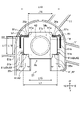
- FIG. 2 is a diagram for explaining absorption of post-molding shrinkage of the fuel tank 1 by the built-in component 10 according to the first embodiment.
- the built-in part 10 is fixed to a parison (not shown), which is a constituent material of the fuel tank 1, by means of upper surfaces 12a and lower surfaces (not shown) of each support 12 fitted in a plurality of fitting portions 15. As shown in FIG. Therefore, when the parison cools and shrinks after molding, a force acts on the struts 12 in the contraction direction of the fuel tank 1 .
- Post-molding shrinkage is usually similar deformation.
- the slidable (movable) post 12 (the post 12 fitted to the slidable fitting portion 13 described later) is attached to the fixed post 12 (the post fitted to the fixed fitting portion 14 to be described later). 12) acts.
- the direction of this force is indicated by a black arrow in the upper diagram of FIG.
- the slidable struts 12 will slide towards the fixed one of the struts 12 .
- the bottom view of FIG. 2 shows the built-in part 10 after sliding.
- FIG. 3 is an external perspective view of the built-in component 10 according to the first embodiment.
- the built-in component 10 comprises a carrier portion 11 , a post 12 , a slidable fitting 13 and a fixed fitting 14 .
- the distance between the post 12 of the slidable fitting 13 having the largest displacement on the XY plane and the post 12 of the fixed fitting 14 is length L2.
- the distance between the columns 12, 12 means the distance between the centers P0, P0 of the columns 12.
- the distances between the struts 12, 12 are partly the same and partly different in the illustrated example, but they may be all the same or all different.
- the carrier part 11 is a rigid body having a fitting part 15 .
- the fitting portion 15 is fitted with the fitted portion 30 (FIG. 5).
- deformation of the carrier portion 11 that accompanies shrinkage after the fuel tank 1 is molded can be suppressed.
- the built-in part 10 when the built-in part 10 is arranged inside the fuel tank 1, the built-in part 10 can be prevented from bending, so that the built-in part 10 can be arranged inside the fuel tank 1 with high accuracy.
- a plurality of fitting portions 15 are provided, and although there are seven in the illustrated example, the number may be two or more and six or less, or may be eight or more.
- the carrier section 11 is configured in a frame shape extending in both the X direction and the Y direction.
- the rigidity of the carrier portion 11 can be improved by configuring it in a frame shape.
- the carrier portion 11 is made of thermoplastic resin such as polyethylene or polystyrene. The shape of the carrier portion 11 will be described with reference to FIG.
- FIG. 4 is a top view of the built-in component 10 according to the first embodiment, showing a state in which the strut 12 is removed.
- the internal component 10 more specifically the fitting 15 , comprises a slidable fitting 13 and a fixed fitting 14 .
- the slidable fitting portion 13 is displaced from the fitting portion 15 (here, the slidable fitting portion 13) of the carrier portion 11 by the post 12 (FIG. 3). , FIG. 5) are slidably fitted to the fitted portion 30 (FIGS. 3 and 5).
- the sliding direction of the post 12 during contraction after molding is defined as the slidable direction.
- the slidable direction is the direction indicated by the black arrow in FIG.
- At least one slidable fitting portion 13 is provided, and although there are six in the illustrated example, the number may be two or more and five or less, or may be seven or more.
- the fitted portion 30 (FIGS. 3 and 5) of the post 12 (FIGS. 3 and 5) is positioned relative to the fitting portion 15 (here, the fixed fitting portion 14) of the carrier portion 11. They are non-slidably fitted. Only one fixed fitting portion 14 is provided in the illustrated example.
- FIG. 4 shows a simplified illustration of the post 12 fitted to the fixed fitting portion 14 .
- a point P is the axial center of the support 12 .
- the slidable direction of at least one (may be one) slidable fitting portion 13 is the direction toward the fixed fitting portion 14 .
- the slidable direction of each of the plurality of slidable fitting portions 13 is the post 12 ( 3 and 5).
- the slidable fitting portion 13 is open on at least one side or the other side in the slidable direction.
- An open portion 21 is formed on the open side.
- the fitted portion 30 FIGS. 3 and 5
- the side of the slidable fitting portion 13 opposite to the fixed fitting portion 14 is opened to form an open portion 21 .
- FIG. 5 is a perspective view of the strut 12 according to the first embodiment.
- the post 12 can be fitted in all the fitting portions 15 of the slidable fitting portion 13 and the fixed fitting portion 14, but for example, it fits into the slidable fitting portion 13.
- the shape of the strut 12 and the shape of the strut 12 fitted to the fixed fitting portion 14 may be different.
- the column 12 includes a columnar supporting column 17 and a fitted portion 30 .
- the fitted portion 30 is fitted to each of the plurality of fitting portions 15 of the carrier portion 11 .
- Support columns 17 having the same shape extend in the +Z direction and the -Z direction of the fitted portion 30, respectively.
- the fitted portion 30 has a rectangular or substantially rectangular flat plate 31 with notches 36 at four corners.
- the fitted portion 30 has a rectangular or substantially rectangular flat plate 33 provided with notches 32 on two of the four sides facing each other (only the notch 32 formed on one side is shown).
- substantially rectangular refers to a substantially rectangular shape when viewed from above, although it is not strictly rectangular. Specifically, for example, the corners are not right-angled, but are rounded by chamfering, for example.
- the fitted portion 30 includes a holding portion 35 .
- the sandwiching portion 35 is fitted to the fitting portion 15 (FIG. 2) by being sandwiched by a flat plate group 34 including a pair of flat plates 31 and 33 arranged to face each other.
- the sandwiching portion 35 includes a prism 18 between the pair of flat plates 31 and 33, both of which have the same dimensions as the length L3 in the X direction and the length L4 in the Z direction of the open portion 21, as shown in FIG.
- FIG. 6 is a perspective view showing a state in which the fitted portion 30 of the post 12 is fitted to the slidable fitting portion 13 according to the first embodiment.
- the length (width) of the open portion 21 in the X direction is L3.
- the length of the slidable fitting portion 13 in the X direction (the portion where the clamping portion 35 is clamped) is a length L3 over the entire Y direction of the slidable fitting portion 13 .
- the length (height) of the open portion 21 in the Z direction is L4.
- the length of the slidable fitting portion 13 in the Z direction (the portion where the holding portion 35 is held) is also the length L4. Therefore, by inserting the to-be-fitted portion 30 into the slidable fitting portion 13 through the open portion 21 , the to-be-fitted portion 30 can be fitted to the slidable fitting portion 13 .
- the slidable fitting portion 13 includes a sliding restricting member 41 that restricts the sliding of the fitted portion 30 toward the opening side where the opening portion 21 is formed. By providing the sliding restricting member 41 , it is possible to prevent the fitted portion 30 fitted in the slidable fitting portion 13 from coming off from the open portion 21 .
- the sliding restricting member 41 is a claw 42 having an inclined surface 42a that rises from the open side (-Y direction) where the open portion 21 is formed toward the back side (+Y direction).
- the rear end of the claw 42 becomes a free end, and the claw 42 can be elastically deformed.
- the inclined surface 42a is pushed in the -Z direction so that the fitted portion 30 can slide in the +Y direction.
- the inclined surface 42 a is lifted in the +Z direction by the reaction force, and the fitted part 30 can be locked to the slidable fitting part 13 .
- FIG. 7 is a top view of FIG. FIG. 7 is a view from the +Z direction to the ⁇ Z direction in FIG.
- the fitting part 30 is locked to the slidable fitting part 13 by bringing the end faces 36a of the two cutouts 36 on the open part 21 side into contact with the ends 42b of the claws 42 .
- the notch 36 is locked by the pawl 42, the Y-direction position of the end 42b of the pawl 42 and the Y-direction position of the front end 18a of the prism 18 substantially match.
- the distance between the end face 43 located on the back side (opposite side to the opening portion 21) when viewed from the opening portion 21 and the end portion 42b of the claw 42 is length L5.
- the distance between the +Y-direction end face 18b of the prism 18 and the -Y-direction end face 36a of the notch 36 is length L6.
- Length L5 is longer than length L6.
- the strut 12 has an end surface 43 and end 42b. The amount of sliding during sliding in the slidable region is the length obtained by subtracting the length L6 from the length L5.
- the length of the flat plate 31 in the X direction is length L7.
- the distance between the sliding restricting members 41, 41 is length L8.
- Length L7 is longer than length L8. Therefore, even if the flat plate 31 tries to slide toward the opening 21 , the flat plate 31 is caught by the sliding restricting members 41 , 41 , and the end surface 43 of the slidable fitting portion 13 and the end 42 b of the pawl 42 are separated from the post 12 . can be placed between
- FIG. 8 is a bottom view of FIG. FIG. 8 is a diagram viewed from the ⁇ Z direction to the +Z direction in FIG. FIG. 8 shows a state in which the end surfaces 36a (FIG. 7) of the two cutouts 36 (FIG. 7) on the open portion 21 side are in contact with the ends 42b (FIG. 7) of the claw 42.
- FIG. 8 is a bottom view of FIG. FIG. 8 is a diagram viewed from the ⁇ Z direction to the +Z direction in FIG. FIG. 8 shows a state in which the end surfaces 36a (FIG. 7) of the two cutouts 36 (FIG. 7) on the open portion 21 side are in contact with the ends 42b (FIG. 7) of the claw 42.
- FIG. 8 is a bottom view of FIG. FIG. 8 is a diagram viewed from the ⁇ Z direction to the +Z direction in FIG. FIG. 8 shows a state in which the end surfaces 36a (FIG. 7) of the two cutouts 36 (FIG.
- the flat plate 33 has cutouts 32 on two of the four sides facing each other.
- the slidable fitting portion 13 is provided with a locking portion 45 at a position facing the notch portion 32 for locking the fitted portion 30 in a temporary state of being fitted to the slidable fitting portion 13 .
- the provisional state here is a state after molding and before shrinkage, specifically, for example, a state before cooling of the parison after blow molding with the built-in part 10 arranged. Therefore, the slidable fitting portion 13 has a positioning mechanism in the slidable direction (Y direction) constituted by the locking portion 45 .
- the locking portion 45 is, for example, a plate spring configured such that the bent portion 45a fits into the notch portion 32 when no stress is applied.
- the column 12 can be locked in a temporary state in which the fitted portion 30 is fitted to the slidable fitting portion 13 .
- the built-in part 10 can be arranged in the fuel tank 1 in a state where the strut 12 is locked.
- a pair of locking portions 45 are provided so as to sandwich the support 12 .
- the length in the X direction between the pair of locking portions 45, 45 is length L9.
- the length in the X direction between the notch portions 32 provided on the two opposing sides is also the length L9.
- the length of the flat plate 33 in the X direction is L10. Length L10 is longer than length L9. Therefore, the support 12 having the flat plate 33 can be locked by the locking portion 45 .
- FIG. 9 is a diagram explaining the movement of the struts 12 during contraction after molding in the first embodiment.
- the cutout portion 32 is locked by the locking portion 45 in the temporary state.
- the interval in the X direction between the locking portions 45, 45 is equal to the interval in the X direction between the notch portions 32, 32, and is a length L9 (FIG. 8).
- the strut 12 slides by a sliding amount L11.
- the amount of sliding L11 of the strut 12 depends on the distance between the slidable fitting portion 13 and the fixed fitting portion 14, and the constituent material of the parison (the member that shrinks after molding in the fuel tank 1) that accommodates the built-in part 10. can be determined from the shrinkage of The distance between the slidable fitting portion 13 and the fixed fitting portion 14 is determined for each support 12 that determines the sliding amount L11.
- the sliding amount of the post 12 of the slidable fitting portion 13 having displacement can be determined based on the length L2, which is the distance on the XY plane between the fixed fitting portion 14 and the post 12 .
- the shrinkage rate of the constituent material of the parison housing the built-in part 10 may be selected from known values according to the constituent material, or may be determined by experiments or the like.
- the magnitude of shrinkage after molding that is, the sliding amount L11 of the strut 12 can be calculated by multiplying the above distance by the above shrinkage ratio.
- the post 12 slides in a slidable area having a length L5 (FIG. 7) in the Y direction formed between the end surface 43 of the slidable fitting portion 13 and the end portion 42b of the pawl 42.
- the length L6 is the distance between the +Y-direction end face 18b of the prism 18 and the -Y-direction end face 36a of the notch 36, as described above. Therefore, if the value obtained by subtracting the length L6 from the length L5 of the sliding portion is equal to or greater than the sliding amount L11, it is possible to suppress movement restriction by the slidable fitting portion 13 during contraction after molding.
- the length of the slidable region in the slidable direction (length L5) is equal to the distance between the slidable fitting portion 13 and the fixed fitting portion 14 (length L2 in the example of FIG. 3). ) and the shrinkage rate of the constituent material of the parison accommodating the built-in part. This makes it possible to estimate the amount of sliding during contraction after molding, and to provide a sufficient slidable area.
- FIGS. 10A and 10B are diagrams for explaining the assembly of the strut 12 to the slidable fitting portion 13 according to the first embodiment.
- the post 12 is assembled to the slidable fitting portion 13 by inserting the post 12 into the opening 21 as indicated by the black arrow.
- the strut 12 is inserted into the open portion 21 so that the arrangement direction (X direction) of the slide restricting members 41 and 41 and the longitudinal direction of the flat plate 31 having the length L5 are the same.
- the post 12 is assembled to the slidable fitting portion 13 as shown in FIGS.
- the built-in component 10 can detect such erroneous assembly.
- FIG. 11 is a diagram for explaining a case in which an erroneous assembly occurs during assembly of FIG.
- the example of FIG. 11 shows a state in which the support 12 is inserted into the open portion 21 while being rotated 90° within the XY plane from the orientation of the support 12 shown in FIG. 10 .
- FIG. 12 is a top view of FIG.
- the length of the flat plate 31 in the lateral direction is length L12.
- the length L12 is longer than the length L3 of the open portion 21 in the X direction. Therefore, even if the post 12 is inserted into the open portion 21 after being rotated 90° in the XY plane from the orientation of the post 12 shown in FIG. Mate.
- the length L12 is longer than the length L8 of the interval between the sliding restricting members 41,41. Therefore, even if the support 12 is inserted into the opening 21 after being rotated 90° in the XY plane from the orientation of the support 12 shown in FIG. It is regulated by the regulating member 41 .
- FIG. 13 is a bottom view of FIG.
- the strut 12 is inserted into the opening 21 while being rotated 90° from the orientation shown in FIG.
- the length of the flat plate 33 in the lateral direction is length L13.
- the length L13 is shorter than the length L9 between the pair of locking portions 45, 45 in the X direction. Therefore, the flat plate 33 does not come into contact with the pair of locking portions 45,45.
- the cutout portion 32 provided on the flat plate 33 and the locking portion 45 provided on the slidable fitting portion 13 do not come into contact with each other. Therefore, in the state shown in FIG. 13, the locking portion 45 does not lock the flat plate 33 of the column 12, and positioning is not performed. As a result, the strut 12 wobbles, and misassembly of the strut 12 at the slidable fitting portion 13 can be detected.
- FIG. 14 is a perspective view of the fixed fitting portion 14 according to the first embodiment.
- the fixed fitting portion 14 includes a sliding restricting member 41 that restricts sliding of the clamping portion 35 of the post 12 .
- the fixed fitting 14 is provided with ribs 51 unlike the slidable fitting 13 .
- a sandwiching portion 35 of the strut 12 is arranged between the rib 51 and the sliding restricting member 41 .
- FIG. 15 is a top view of FIG. 14.
- FIG. A pair of ribs 51 are provided symmetrically so as to sandwich the flat plate 31 .
- the rib 51 may have a shape that can regulate the position of the flat plate 31 in the Y direction. It extends in two parallel directions (X direction).
- the ribs 51 include ribs 51c extending in the X direction and ribs 51b extending in the Y direction. Of these, the rib 51c can position the column 12 in the X direction when the column 12 is fixed.
- the rib 51b can guide the insertion in the +Y direction when the post 12 is inserted from the open portion 21, details of which will be described later with reference to FIG.
- the distance between the ⁇ X direction end 51a of one rib 51 and the +X direction end 51a of the other rib 51 is length L14.
- the length L14 is slightly longer than the length L15 of the end face 31a of the end face of the flat plate 31 extending in the X direction, excluding the cutout portion 36 . Therefore, a portion of the flat plate 31 is arranged between the ends 51a, 51a. Thereby, the support 12 having the flat plate 31 is positioned in the X direction.
- the distance between the ribs 51b, 51b is length L16. Length L16 is longer than length L7, which is the length of flat plate 31 in the X direction. Therefore, the flat plate 31 is arranged between the ribs 51b, 51b.
- ribs 51b extending in the Y direction face end surfaces 31b of the flat plate 31 extending in the same direction (Y direction) as the slidable direction.
- the rib 51 c faces the Y-direction end surfaces 36 a of the two notch portions 36 arranged farther from the open portion 21 .
- the rib 51c is arranged on the side opposite to the open portion 21 when viewed from the end surface 36a.
- the post 12 with the flat plate 31 is fixed.
- one side of the fixed fitting portion 14 is open to form an open portion 21, and the other end side is formed with an end face 43 (closed end face).
- the fixed fitting portion 14 includes a sliding restricting member 41 between the open portion 21 and the end surface 43 that restricts sliding of the clamping portion 35 .
- the holding portion 35 is engaged with the sliding restricting member 41 and the end surface 43 .
- the Y-direction position of the end face 18b of the prism 18 forming the holding portion 35 substantially coincides with the Y-direction position of the end face 43 of the fixed fitting portion 14 . That is, the end surface 18b contacts the end surface 43. As shown in FIG.
- the Y-direction positions of the end faces 36 a of the two notch portions 36 on the open portion 21 side substantially coincide with the Y-direction positions of the end portions 42 b of the claws 42 constituting the sliding restricting member 41 . That is, the end portion 42b contacts the end surface 36a. By doing so, the post 12 can be fixed to the fixed fitting portion 14 .
- the distance between the rib 51c and the end portion 42b of the sliding restricting member 41 is length L17.
- the length of the end surface 31b of the end surface of the flat plate 31 extending in the Y direction, excluding the notch 36, is L18.
- Length L17 is longer than length L18. Therefore, the flat plate 31 is arranged between the end portion 42b of the slide restricting member 41 and the rib 51c.
- 16A and 16B are diagrams for explaining the assembly of the post 12 to the fixed fitting portion 14 according to the first embodiment.
- the post 12 By inserting the post 12 into the open portion 21 as indicated by the black arrow, the post 12 is attached to the fixed fitting portion 14 .
- the strut 12 is inserted into the open portion 21 so that the arrangement direction (X direction) of the slide restricting members 41 and 41 and the longitudinal direction of the flat plate 31 having the length L5 are the same.
- the insertion of the strut 12 in the +Y direction is guided by the rib 51b.
- the post 12 is assembled to the fixed fitting portion 14 as shown in FIGS. 14 and 15 .
- the built-in component 10 can detect such erroneous assembly.
- FIG. 17 is a diagram for explaining a case where incorrect assembly occurs during assembly of FIG.
- the example of FIG. 17 shows a state in which the support 12 is inserted into the open portion 21 while being rotated 90° within the XY plane from the orientation of the support 12 shown in FIG. 16 .
- FIG. 18 is a top view of FIG. 17.
- the distance between the sliding restricting members 41, 41 is length L8.
- the length of the flat plate 31 in the lateral direction is L12. Length L12 is longer than length L8. Therefore, when the strut 12 is inserted into the open portion 21, the flat plate 31 is arranged on the sliding restricting members 41,41.
- the length in the X direction of the end face 31a of the end face 31a of the flat plate 31 extending in the X direction, excluding the notch 36, is L15.
- the distance between the rib 51c and the end portion 42b of the sliding restricting member 41 is a length L17.
- Length L14 is longer than length L17. Therefore, even if the flat plate 31 is inserted all the way through the open portion 21, the flat plate 31 does not fit between the rib 51c and the end portion 42b of the sliding restricting member 41, and the sliding restricting members 41, 41 do not fit. remains placed in the As a result, the post 12 is not fixed, and the post 12 can be pulled out with a little force, so that misassembly of the post 12 at the fixing fitting portion 14 can be detected.
- the fitted portion 30 of the strut 12 is slidably fitted to the fitting portion 15 of the carrier portion 11 . Therefore, the carrier portion 11 itself can be prevented from becoming non-rigid, and the built-in component 10 can be accurately arranged in the fuel tank 1 . As a result, the post-molding shrinkage of the fuel tank 1 can be absorbed appropriately.
- the slidable direction of the plurality of slidable fitting portions 13 is the direction toward the fixed fitting portion 14 . Therefore, displacement due to contraction after molding of the complicated fuel tank 1 can be absorbed more than before. As a result, separation of the strut 12 from the fuel tank 1 due to post-molding shrinkage can be suppressed, and the reliability of the fuel tank 1 can be improved.
- the fuel tank according to the second embodiment mainly differs from the first embodiment described above in that the fitting portion 15A is provided with an urging portion (for example, a leaf spring).
- an urging portion for example, a leaf spring
- FIG. 19 is an external perspective view of the built-in component 10A according to the second embodiment.
- the built-in component 10A includes a carrier portion 11A, a post 12A, a slidable fitting portion 13A, and a fixed fitting portion 14A.
- the slidable fitting portions 13A (here, six locations) are slidably fitted with the struts 12A.
- the sliding direction of the strut 12 is generally the same as in the first embodiment (see FIG. 4).
- the support 12A is non-slidably fitted to the fixed fitting portion 14A (here, one place).
- FIG. 20 is a perspective view of the strut 12A according to the second embodiment.
- the post 12A can be fitted into all the fitting portions 15A of the slidable fitting portion 13A and the fixed fitting portion 14A, but for example, it fits into the slidable fitting portion 13A.
- the shape of the column 12A and the shape of the column 12A fitted to the fixed fitting portion 14A may be different.
- the column 12A includes a columnar supporting column 17 and a fitted portion 30A.
- the fitted portion 30A is a portion that is fitted to each of the plurality of fitting portions 15A of the carrier portion 11 .
- Support columns 17 having the same shape extend in the +Z direction (upward direction) and -Z direction (downward direction), which are the height directions of the fitted portion 30A.
- the end surface of each support column 17 is fixed to the opposing inner surface of the tank body.
- the fitted portion 30A has a flat plate 31A having notch portions 36A, 36A at two corners on the +Y side (see also FIG. 23).
- Temporary engagement portions (notches) 132 are formed on two sides of the four sides of the flat plate 31A that face each other in the X direction. The temporary engaging portion 132 is cut out at the end of the flat plate 31A so as to open in the +X direction or the -X direction.
- the fitted portion 30A includes a flat plate 33A arranged below the flat plate 31A and spaced from the flat plate 31A.
- the flat plate 33A has approximately the same size as the flat plate 31A and has a rectangular or substantially rectangular shape. It should be noted that the term “substantially rectangular” as used herein refers to a substantially rectangular shape when viewed from above, although it is not strictly rectangular. Specifically, for example, the corners are not right-angled, but are rounded by chamfering, for example.
- the fitted portion 30A includes a holding portion 35A.
- the clamping portion 35A is a portion that is fitted into the fitting portion 15A (FIG. 19) by being clamped by a flat plate group 34A including a pair of flat plates 31A and 33A arranged to face each other.
- the sandwiching portion 35A includes a solid column portion 138 (see the dotted line portion in FIG. 23) in the gap between the pair of flat plates 31A and 33A, and a plurality of intermediate ribs 139 (here, 4).
- the intermediate ribs 139 are arranged parallel to each other along the Y direction. As shown in FIG. 20, out of the intermediate ribs 139, the intermediate ribs 139A, 139A located on both outer sides extend longer in the -Y direction than the intermediate ribs 139B, 139B located in the center.
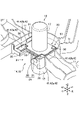
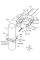
- FIG. 21 is an exploded perspective view illustrating assembly of the post 12A to the slidable fitting portion 13A according to the second embodiment.
- the slidable fitting portion 13A includes a base portion 111, a concave portion 112, a guide 113 with a stopper, and an urging portion 114.
- the base 111 is a plate-like member and has a substantially horseshoe shape when viewed from above.
- a side wall 116 rising from the base portion 111 is provided at the peripheral portion of the base portion 111 .
- the recessed portion 112 is a recessed portion that opens toward the open portion 21 side ( ⁇ Y side) and is a portion to which the support column 12A is fitted.
- Relief portions 117 and 117 are formed on both sides in the X direction on the +Y side end face 112a of the recess 112 .
- the relief portion 117 is a portion that is slightly recessed on the +Y side from the end surface 112 a of the recess portion 112 .
- the escape portion 117 may be omitted, providing the escape portion 117 as in the present embodiment can reliably avoid interference with the post 12A when the post 12A slides.
- the base 111 has a horseshoe shape in plan view has been exemplified, it may have another shape.
- a pair of guides 113 with stoppers are provided on the -Y side of the base 111 .
- the height dimension of the guide 113 with stopper is smaller than the dimension of the gap between the flat plates 31A and 33A. That is, the guide 113 with a stopper is formed so as to be able to pass through the gap between the flat plates 31A and 33A.
- the stopper-equipped guide 113 includes an arm portion 113a and a claw portion 113b.
- the arm portion 113a extends obliquely from the ⁇ Y side end of the side wall 116 toward the center, and has a free end.
- the claw portion 113b is a plate-like portion provided at the tip of the arm portion 113a and arranged parallel to the X direction. Since the arm portions 113a, 113a extend in the +Y direction and are inclined toward the center in the direction of approaching each other, the support column 12A can be guided to the concave portion 112. As shown in FIG.
- the distance between the guides 113, 113 with stoppers is smaller than the distance between the intermediate ribs (the distance between the outer intermediate ribs 139A, 39A).
- the guides 113, 113 with stoppers may be pushed open so that the support 12A can be removed.
- the urging portions 114 are formed on both sides of the base portion 111 in the X direction with the concave portion 112 interposed therebetween.
- the biasing portion 114 is configured by a leaf spring that is rectangular in plan view and rises from the base portion 111 in the +Z direction.
- the biasing portion 114 extends in the +Y direction from the -Y side and is formed at a position corresponding to the opening 115 (see FIG. 23) that opens in the base portion 111 . Since the tip side (+Y side) of the biasing portion 114 is a free end, the biasing portion 114 has elasticity.
- the urging portion 114 has a base end portion 114 a forming a large angle with the base portion 111 and formed on the base end side, and a tip end portion 114 b formed on the tip end side forming a small angle with the base portion 111 .
- a temporary locking rib 118 extending in the X direction and having a convex shape is formed on the upper surface of the tip portion 114b.
- the temporary locking rib 118 is formed to engage with a temporary engaging portion (notch portion) 132 of the flat plate 31A.
- the height dimension from the base portion 111 to the tip portion 114b is larger than the gap dimension between the flat plates 31A and 33A before the support 12A is fitted.
- the cutout portions 36A, 36A of the post 12A are opposed to the slidable fitting portion 13A, and both are fitted.
- the notches 36A, 36A serve as marks to prevent misassembly.
- guides 113, 113 with stoppers are inserted into gaps between flat plates 31A, 33A of column 12A to enter slidable fitting portion 13A.
- the post 12A is guided by the guides 113, 113 with stoppers.
- the temporary locking rib 118 of the biasing portion 114 enters into and engages with the temporary engaging portion 132 of the flat plate 31A as shown in FIGS. 22-24. This state is the "temporary engagement state”.
- the stopper-equipped guides 113, 113 are restored to their original states and face the intermediate ribs 139A, 139A.
- the distance LA of the gap S from the end surface 112a of the recess 112 to the intermediate rib 139 is the sliding allowance for the strut 12A to slide when molding the fuel tank.
- the distance LA may be constant for each slidable fitting portion 13A, or may vary. It is preferable to appropriately set the distance LA according to the degree of post-molding shrinkage.
- Each intermediate rib 139 has a constant length on the +Y side.
- the lower surface 111b of the base 111 and the upper surface (lower contact surface) 33Aa of the flat plate 33A are in contact or surface contact.
- the tip portion 114b of the biasing portion 114 which is a leaf spring, and the lower surface (upper contact surface) 31Aa of the flat plate 31A come into contact or surface contact. Since the biasing portion 114 biases the base portion 111 upward, it is possible to prevent the column 12 ⁇ /b>A from tilting with respect to the base portion 111 .
- the biasing portion 114 enters between the upper surface (lower contact surface) 33Aa of the flat plate 33A and the lower surface (upper contact surface) 31Aa of the flat plate 31A, and the upper surface (lower contact surface) 33Aa and the lower surface (upper contact surface). Since the urging force is generated in the direction in which 31Aa separates, rattling of the support 12A with respect to the base 111 can be suppressed. Further, since the temporary locking rib 118 of the biasing portion 114 engages the temporary engaging portion (notch portion) 132 of the flat plate 31A, the position in the depth direction (Y direction) is determined. This makes it possible to easily position the post 12A with respect to the slidable fitting portion 13A.
- the temporary locking rib 118 of the biasing portion 114 and the temporary engaging portion 132 of the flat plate 31A are preferably formed in a size and shape that allows the temporary engaging state to be released when shrinkage occurs after molding.
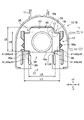
- FIG. 25 is a top view showing a state in which the fitted portion of the column 12A is fitted to the fixed fitting portion 14A according to the second embodiment.
- the fixed fitting portion 14A differs from the slidable fitting portion 13A in that the post 12A does not slide from the provisionally engaged state.
- the temporary engagement state is reached, the post 12A is fitted into the concave portion 112 in the same manner as the slidable fitting portion 13A, and the temporary engagement portion 132 of the flat plate 31A and the temporary locking rib 118 of the urging portion 114 are engaged. engages.
- the end surface 112a of the concave portion 112 and each intermediate rib 139 are in contact with each other or face each other with a small gap therebetween.
- the fixed fitting portion 14A is formed so that the post 12A is restrained and does not slide from the provisionally engaged state.
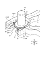
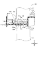
- FIG. 26 is a XXIV-XXIV arrow view of FIG. 22 showing the state after the strut 12A has slid.
- the post 12A fitted to the slidable fitting portion 13A slides toward the fixed fitting portion 14A.
- the temporary locking rib 118 of the biasing portion 114 is disengaged from the temporary engaging portion 132 of the flat plate 31A, and the slidable fitting portion 13A (carrier portion 11A) is The strut 12A moves in the +Y direction (back side of the slidable fitting portion 13A).
- the provisional engagement is released and the relative displacement between the two is released. It has a temporary engagement structure that allows When the post-molding shrinkage is completed, the strut 12A is fixed (fixed) to the parison (the opposing inner surface of the tank body) at that position.
- the biasing force of the biasing portion 114 can suppress the tilting of the strut 12A with respect to the slidable fitting portion 13A (carrier portion 11A). Thereby, the molding accuracy of the fuel tank can be improved.
- the biasing structure can be configured easily.
- the biasing portion 114 may have another form.
- the urging portion 114 may enter between the flat plate 31A and the flat plate 33A and urge them in a direction to separate them.
- the biasing portion 114 brings the upper surface of the tip portion 114b of the biasing portion 114 into surface contact with the lower surface (upper contact surface) 31Aa of the flat plate 31A. , the temporary engagement state can be stably maintained. Further, by providing a pair of urging portions 114 on both sides of the concave portion 112 in the X direction, the engaged state can be maintained more stably.
- the struts slide when shrinkage occurs after molding. good.
- the provisional engagement structure provisional engagement rib 118 and provisional engagement portion 132
- the upper contact surface is the lower surface of the flat plate 31A and the lower contact surface is the upper surface of the flat plate 33A, but the upper contact surface and the lower contact surface may be surfaces in other parts.
- the biasing portion 114 extends from the -Y direction to the +Y direction, but may extend in other directions. Also, the plurality of urging portions 114 may extend in the same direction, or may extend in different directions. Further, the biasing portion 114 may be arranged so as to surround the support 12A. Further, in the present embodiment, the tip portion 114b of the biasing portion 114 contacts the flat plate 31A, but the tip portion 114b of the biasing portion 114 may contact the flat plate 33A.
Abstract
Description
しかし、本発明によれば、支柱とキャリア部とが相対変位するため、成形後収縮に応じて支柱の位置も追従して摺動することができる。また、仮係合構造を備えることで、嵌合部と支柱との間の位置決めをすることができる。これにより、各支柱の摺動距離がコントロールし易くなり、成形精度をより高めることができる。 When molding the fuel tank, the parison hardens and shrinks after molding, so there is a risk that the struts will shift and be fixed to the fuel tank.
However, according to the present invention, since the column and the carrier portion are displaced relative to each other, the position of the column can follow and slide according to shrinkage after molding. In addition, provision of the provisional engagement structure enables positioning between the fitting portion and the post. This makes it easier to control the sliding distance of each strut, and it is possible to further improve the molding accuracy.
以下、本発明の第一実施形態(本実施形態)を説明する。ただし、本発明は以下の内容及び図示の内容になんら限定されず、本発明の効果を著しく損なわない範囲で任意に変形して実施できる。本発明は、異なる実施形態同士を組み合わせて実施できる。以下の記載において、異なる実施形態において同じ部材については同じ符号を付し、重複する説明は省略する。また、同じ機能のものについては同じ名称を使用し、重複する説明は省略する。 [First embodiment]
A first embodiment (this embodiment) of the present invention will be described below. However, the present invention is by no means limited to the following content and the content of the drawings, and can be arbitrarily modified within the scope that does not significantly impair the effects of the present invention. The present invention can be practiced by combining different embodiments. In the following description, the same reference numerals are given to the same members in different embodiments, and overlapping descriptions are omitted. In addition, the same names are used for those with the same functions, and overlapping explanations are omitted.
の内壁からの剥離又は脱離を抑制できる。この結果、成形後収縮後においても燃料タンク1の内部に内蔵部品10を保持でき、内蔵部品10による使用時等の燃料タンク1の変形を抑制できる。 In this way, by sliding the
can suppress peeling or detachment from the inner wall of the As a result, the built-in
と端部42bとの間に形成される摺動可能領域において摺動する。摺動可能領域での摺動時の摺動量は、長さL5から長さL6を引いた長さである。 In the slidable fitting portion 13, the distance between the
and end 42b. The amount of sliding during sliding in the slidable region is the length obtained by subtracting the length L6 from the length L5.
によって決定してもよい。 As shown in the lower diagram of FIG. 9, the
次に、本発明の第二実施形態について説明する。第二実施形態に係る燃料タンクは、嵌合部15Aに、付勢部(例えば、板ばね)を備えている点で前記した第一実施形態と主に相違する。第二実施形態では、第一実施形態と相違する部分を中心に説明する。 [Second embodiment]
Next, a second embodiment of the invention will be described. The fuel tank according to the second embodiment mainly differs from the first embodiment described above in that the
しかし、本実施形態によれば、摺動可能嵌合部13Aにおいて、支柱12Aとキャリア部11Aとが相対変位することができるため、成形後収縮に応じて支柱12Aの位置も追従して摺動する。成形後収縮に応じて摺動代を設定することで、所望の位置に支柱12Aを固定させることができる。また、仮係合構造(仮係止リブ118及び仮係合部132)を備えることで、嵌合部(摺動可能嵌合部13A)と支柱12Aとの間の位置決めをすることができる。これにより、各支柱12Aの摺動距離がコントロールし易くなり、成形精度をより高めることができる。 In addition, in the conventional technology, when the fuel tank is molded, post-molding shrinkage occurs when the parison hardens, so there is a risk that the position of the built-in part (pillar) will be shifted relative to the fuel tank and fixed.
However, according to this embodiment, since the
10 内蔵部品
11 キャリア部
12 支柱
13 摺動可能嵌合部
14 固定嵌合部
15 嵌合部
30 被嵌合部
32 切り欠き部
33 平板
35 挟持部
36 切り欠き部
41 摺動規制部材
42 爪
42a 傾斜面
42b 端部
43 端面(閉塞端面)
45 係止部
10A 内蔵部品
11A キャリア部
12A 支柱
13A 摺動可能嵌合部
14A 固定嵌合部
15A 嵌合部
31A 平板
31Aa 平板31Aの下面(上部接触面)
33A 平板
33Aa 平板33Aの上面(下部接触面)
111 基部
114 付勢部(板ばね)
118 仮係止リブ
132 仮係合部 1
45 locking
33A flat plate 33Aa upper surface (lower contact surface) of
111
118
Claims (3)
- 内蔵部品を有する燃料タンクであって、
前記内蔵部品は、複数の嵌合部を有する剛体であるキャリア部と、前記複数の嵌合部のそれぞれに嵌合される被嵌合部を有する複数の支柱と、を備え、
前記支柱の被嵌合部は、高さ方向に離間して形成された上部接触面及び下部接触面を有し、
前記キャリア部の嵌合部は、前記支柱との嵌合時に前記上部接触面と前記下部接触面との間に入りこみ、前記上部接触面と前記下部接触面とが離間する方向に付勢力を生じさせる付勢部を有することを特徴とする燃料タンク。 A fuel tank having built-in parts,
The built-in component includes a carrier portion that is a rigid body having a plurality of fitting portions, and a plurality of struts having fitted portions that are fitted to the plurality of fitting portions, respectively;
The fitted portion of the support has an upper contact surface and a lower contact surface spaced apart in the height direction,
The fitting portion of the carrier portion enters between the upper contact surface and the lower contact surface when fitting with the support, and generates a biasing force in the direction in which the upper contact surface and the lower contact surface are separated from each other. A fuel tank characterized by having an urging portion for urging. - 前記付勢部に仮係止リブを設けるとともに、前記被嵌合部に仮係合部をそれぞれ設け、前記仮係止リブと前記仮係合部とが仮係合する一方、前記支柱と前記キャリア部との間に相対変位が生じた場合に仮係合が解かれ、両者の相対変位を許容する仮係合構造を有することを特徴とする請求項1に記載の燃料タンク。 A temporary locking rib is provided on the urging portion, and a temporary engaging portion is provided on the fitted portion. 2. The fuel tank according to claim 1, further comprising a provisional engagement structure that releases the provisional engagement when relative displacement occurs between the fuel tank and the carrier portion, thereby permitting the relative displacement between the two.
- 前記嵌合部の付勢部は、基部から高さ方向に延設された板ばねであることを特徴とする請求項1又は請求項2に記載の燃料タンク。
3. The fuel tank according to claim 1, wherein the biasing portion of the fitting portion is a plate spring extending in the height direction from the base portion.
Priority Applications (4)
| Application Number | Priority Date | Filing Date | Title |
|---|---|---|---|
| JP2022581273A JP7445792B2 (en) | 2021-02-12 | 2022-01-17 | fuel tank |
| CN202280010277.5A CN116723951A (en) | 2021-02-12 | 2022-01-17 | Fuel tank |
| EP22751251.4A EP4292794A1 (en) | 2021-02-12 | 2022-01-17 | Fuel tank |
| US18/546,040 US20240123818A1 (en) | 2021-02-12 | 2022-01-17 | Fuel tank |
Applications Claiming Priority (2)
| Application Number | Priority Date | Filing Date | Title |
|---|---|---|---|
| JP2021-020630 | 2021-02-12 | ||
| JP2021020630 | 2021-02-12 |
Publications (1)
| Publication Number | Publication Date |
|---|---|
| WO2022172695A1 true WO2022172695A1 (en) | 2022-08-18 |
Family
ID=82837704
Family Applications (1)
| Application Number | Title | Priority Date | Filing Date |
|---|---|---|---|
| PCT/JP2022/001376 WO2022172695A1 (en) | 2021-02-12 | 2022-01-17 | Fuel tank |
Country Status (5)
| Country | Link |
|---|---|
| US (1) | US20240123818A1 (en) |
| EP (1) | EP4292794A1 (en) |
| JP (1) | JP7445792B2 (en) |
| CN (1) | CN116723951A (en) |
| WO (1) | WO2022172695A1 (en) |
Citations (7)
| Publication number | Priority date | Publication date | Assignee | Title |
|---|---|---|---|---|
| JP2002536586A (en) * | 1999-02-08 | 2002-10-29 | サルフレックス ポリマーズ リミテッド | Fuel tank deflection prevention device |
| JP2003170751A (en) * | 2001-12-04 | 2003-06-17 | Yachiyo Industry Co Ltd | Noise suppressor for fuel tank |
| WO2014053285A1 (en) * | 2012-10-02 | 2014-04-10 | Kautex Textron Gmbh & Co. Kg | Container of thermoplastic material |
| JP2018053878A (en) * | 2016-09-30 | 2018-04-05 | ダイハツ工業株式会社 | Fuel tank |
| JP2018187853A (en) | 2017-05-09 | 2018-11-29 | 株式会社Fts | Blow molding method |
| JP2018192910A (en) * | 2017-05-17 | 2018-12-06 | 愛三工業株式会社 | Tank deformation inhibition device and fuel tank device |
| JP2021008261A (en) * | 2019-05-31 | 2021-01-28 | テーイー オートモーティブ テクノロジー センター ゲゼルシャフト ミット ベシュレンクテル ハフツング | Fuel tank with reinforcement device |
-
2022
- 2022-01-17 US US18/546,040 patent/US20240123818A1/en active Pending
- 2022-01-17 WO PCT/JP2022/001376 patent/WO2022172695A1/en active Application Filing
- 2022-01-17 CN CN202280010277.5A patent/CN116723951A/en active Pending
- 2022-01-17 EP EP22751251.4A patent/EP4292794A1/en active Pending
- 2022-01-17 JP JP2022581273A patent/JP7445792B2/en active Active
Patent Citations (7)
| Publication number | Priority date | Publication date | Assignee | Title |
|---|---|---|---|---|
| JP2002536586A (en) * | 1999-02-08 | 2002-10-29 | サルフレックス ポリマーズ リミテッド | Fuel tank deflection prevention device |
| JP2003170751A (en) * | 2001-12-04 | 2003-06-17 | Yachiyo Industry Co Ltd | Noise suppressor for fuel tank |
| WO2014053285A1 (en) * | 2012-10-02 | 2014-04-10 | Kautex Textron Gmbh & Co. Kg | Container of thermoplastic material |
| JP2018053878A (en) * | 2016-09-30 | 2018-04-05 | ダイハツ工業株式会社 | Fuel tank |
| JP2018187853A (en) | 2017-05-09 | 2018-11-29 | 株式会社Fts | Blow molding method |
| JP2018192910A (en) * | 2017-05-17 | 2018-12-06 | 愛三工業株式会社 | Tank deformation inhibition device and fuel tank device |
| JP2021008261A (en) * | 2019-05-31 | 2021-01-28 | テーイー オートモーティブ テクノロジー センター ゲゼルシャフト ミット ベシュレンクテル ハフツング | Fuel tank with reinforcement device |
Also Published As
| Publication number | Publication date |
|---|---|
| CN116723951A (en) | 2023-09-08 |
| JPWO2022172695A1 (en) | 2022-08-18 |
| JP7445792B2 (en) | 2024-03-07 |
| EP4292794A1 (en) | 2023-12-20 |
| US20240123818A1 (en) | 2024-04-18 |
Similar Documents
| Publication | Publication Date | Title |
|---|---|---|
| JP3136978B2 (en) | Air cleaner | |
| US8763836B2 (en) | Modular equipment case with sealing system | |
| EP1120738B1 (en) | Memory card | |
| CN110778798B (en) | Hinge structure | |
| EP0260876B1 (en) | Disk cartridge | |
| WO2022172695A1 (en) | Fuel tank | |
| JP7153164B2 (en) | fuel tank | |
| KR101103965B1 (en) | Push-up device | |
| CN108058648B (en) | Storage box | |
| JP5238845B2 (en) | Slide core device | |
| EP3252857B1 (en) | Fuel battery gasket | |
| JP7445825B2 (en) | fuel tank | |
| US10232803B2 (en) | Temporary placement structure for sub cover | |
| JP4459015B2 (en) | Substrate storage container | |
| WO2021234808A1 (en) | Substrate storage container | |
| US20210028573A1 (en) | Terminal protection device of connector | |
| US20210324665A1 (en) | Hood lock device attachment structure | |
| JP2020009981A (en) | Substrate housing container | |
| KR102449263B1 (en) | Battery Module Case for Electric Vehicle | |
| JP7207209B2 (en) | Vehicle containment device | |
| JP7134580B2 (en) | Mounting structure of fuel filler cap | |
| US20210367304A1 (en) | Combination of container and mountable component, and container | |
| TWI697979B (en) | Substrate container | |
| KR20240006954A (en) | The assembly structure of the baffle and the baffle and the tank in which the baffle is assembled | |
| KR200210019Y1 (en) | Box to take charge of photomask |
Legal Events
| Date | Code | Title | Description |
|---|---|---|---|
| 121 | Ep: the epo has been informed by wipo that ep was designated in this application |
Ref document number: 22751251 Country of ref document: EP Kind code of ref document: A1 |
|
| ENP | Entry into the national phase |
Ref document number: 2022581273 Country of ref document: JP Kind code of ref document: A |
|
| WWE | Wipo information: entry into national phase |
Ref document number: 202280010277.5 Country of ref document: CN |
|
| WWE | Wipo information: entry into national phase |
Ref document number: 18546040 Country of ref document: US |
|
| WWE | Wipo information: entry into national phase |
Ref document number: 2022751251 Country of ref document: EP |
|
| NENP | Non-entry into the national phase |
Ref country code: DE |
|
| ENP | Entry into the national phase |
Ref document number: 2022751251 Country of ref document: EP Effective date: 20230912 |