WO2022172392A1 - 検証システム、検証方法および検証プログラム - Google Patents
検証システム、検証方法および検証プログラム Download PDFInfo
- Publication number
- WO2022172392A1 WO2022172392A1 PCT/JP2021/005213 JP2021005213W WO2022172392A1 WO 2022172392 A1 WO2022172392 A1 WO 2022172392A1 JP 2021005213 W JP2021005213 W JP 2021005213W WO 2022172392 A1 WO2022172392 A1 WO 2022172392A1
- Authority
- WO
- WIPO (PCT)
- Prior art keywords
- verification
- surrogate model
- unit
- data
- analysis target
- Prior art date
Links
- 238000012795 verification Methods 0.000 title claims abstract description 288
- 238000000034 method Methods 0.000 title claims description 75
- 238000004458 analytical method Methods 0.000 claims abstract description 108
- 238000010276 construction Methods 0.000 claims abstract description 37
- 238000011156 evaluation Methods 0.000 claims description 94
- 230000007547 defect Effects 0.000 claims description 55
- 230000006399 behavior Effects 0.000 claims description 36
- 230000006870 function Effects 0.000 claims description 7
- 238000004088 simulation Methods 0.000 description 16
- 238000010586 diagram Methods 0.000 description 15
- 238000013500 data storage Methods 0.000 description 10
- 238000012545 processing Methods 0.000 description 9
- 238000013461 design Methods 0.000 description 8
- 238000011161 development Methods 0.000 description 8
- 238000004891 communication Methods 0.000 description 6
- 239000000446 fuel Substances 0.000 description 6
- 238000012360 testing method Methods 0.000 description 6
- 238000002347 injection Methods 0.000 description 4
- 239000007924 injection Substances 0.000 description 4
- 230000010354 integration Effects 0.000 description 4
- 239000000243 solution Substances 0.000 description 4
- 238000006073 displacement reaction Methods 0.000 description 3
- 230000010365 information processing Effects 0.000 description 3
- 238000004364 calculation method Methods 0.000 description 2
- 238000005259 measurement Methods 0.000 description 2
- 230000002159 abnormal effect Effects 0.000 description 1
- 230000005856 abnormality Effects 0.000 description 1
- 238000002790 cross-validation Methods 0.000 description 1
- 238000001514 detection method Methods 0.000 description 1
- 230000002349 favourable effect Effects 0.000 description 1
- 238000007429 general method Methods 0.000 description 1
- 238000010801 machine learning Methods 0.000 description 1
- 230000002250 progressing effect Effects 0.000 description 1
Images


Classifications
-
- G—PHYSICS
- G06—COMPUTING; CALCULATING OR COUNTING
- G06F—ELECTRIC DIGITAL DATA PROCESSING
- G06F30/00—Computer-aided design [CAD]
- G06F30/20—Design optimisation, verification or simulation
- G06F30/27—Design optimisation, verification or simulation using machine learning, e.g. artificial intelligence, neural networks, support vector machines [SVM] or training a model
-
- G—PHYSICS
- G06—COMPUTING; CALCULATING OR COUNTING
- G06F—ELECTRIC DIGITAL DATA PROCESSING
- G06F30/00—Computer-aided design [CAD]
- G06F30/10—Geometric CAD
- G06F30/15—Vehicle, aircraft or watercraft design
Definitions
- the present invention relates to a verification system, verification method, and verification program that perform verification using a surrogate model.
- a method using a surrogate model is also known as a method of performing simulations at high speed.
- a surrogate model is a model that substitutes simulation-based evaluation, and is used to derive an approximate solution at high speed.
- Patent Literature 1 describes product design and simulation using a surrogate model.
- an object of the present invention is to provide a verification system, a verification method, and a verification program that can reduce the cost required for a verification process using a surrogate model.
- a verification system includes surrogate model construction means for constructing a surrogate model that simulates the behavior of the analysis target using operation data to be analyzed as learning data, and Originally, a surrogate model selection means for selecting a surrogate model that is judged to reproduce the behavior of the analysis target based on the operation data according to the verification content, and a verification means for verifying the analysis target using the selected surrogate model. characterized by comprising
- the verification method uses operation data to be analyzed as learning data to construct a surrogate model that simulates the behavior of the analysis object, and from the operation data to be analyzed, verification content under specified conditions A surrogate model that is judged to reproduce the behavior of the analysis object most accurately based on the operation data according to the condition is selected, and the analysis object is verified using the selected surrogate model.
- a verification program provides a computer with a surrogate model construction process for constructing a surrogate model that simulates the behavior of an analysis target using operation data to be analyzed as learning data, and a specified Under conditions, a surrogate model selection process that selects a surrogate model that is judged to reproduce the behavior of the analysis target based on the operation data according to the verification details, and the analysis target is verified using the selected surrogate model. It is characterized by executing verification processing.
- the cost required for the verification process using surrogate models can be reduced.
- FIG. 1 is a block diagram showing a configuration example of a first embodiment of a verification system according to the present invention
- FIG. It is a block diagram which shows the structural example of the verification part of 1st embodiment.
- 4 is a flow chart showing an operation example of the verification system of the first embodiment
- 4 is a flow chart showing an operation example of a verification unit of the first embodiment
- FIG. 4 is a block diagram showing a configuration example of a verification system according to a second embodiment of the present invention
- FIG. 11 is a block diagram showing a configuration example of a verification unit according to the second embodiment
- FIG. 9 is a flow chart showing an operation example of a verification unit according to the second embodiment
- FIG. 11 is a block diagram showing a configuration example of a verification system according to a third embodiment of the present invention. It is explanatory drawing which shows the example which visualized the surrogate model of each unit.
- FIG. 12 is a block diagram showing a configuration example of a verification unit according to the third embodiment; FIG. It is a flow chart which shows an example of operation of a verification part of a third embodiment.
- 1 is a block diagram showing an overview of a verification system according to the invention; FIG.
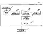
- FIG. 1 is a block diagram showing a configuration example of a first embodiment of a verification system according to the present invention.
- the verification system 100 of this embodiment is a system that verifies an analysis target using a surrogate model. Since the surrogate model described above can be said to be a model capable of narrowing down the approximate solution, the verification system 100 of the present embodiment can be said to be a system that performs verification using the surrogate model capable of narrowing down the approximate solution.
- the verification system 100 of the present embodiment includes a data acquisition unit 10, a data storage unit 20, a surrogate model construction unit 30, a surrogate model storage unit 40, a surrogate model evaluation unit 50, a surrogate model selection unit 60, a verification a portion 170;
- the verification system 100 is connected to an output device 70 that outputs various processing results.
- the output device 70 is realized by, for example, a display device or a printer. Also, the output device 70 may be realized as a control device that outputs control information according to the processing result to each unit.
- the data acquisition unit 10 acquires data used for various processes by the verification system 100 and stores the data in the data storage unit 20 .
- the verification system 100 is used in automobile design development. In other words, in this embodiment, the verification system 100 is used to verify the operating state of the automobile and the situation when a problem occurs.
- the object for which the verification system 100 of the present invention is used is not limited to the design and development of automobiles, and may be, for example, the design and development of motorcycles and the design and development of various control devices.
- the data acquisition unit 10 acquires operation data and verification data to be analyzed.
- the operating data to be analyzed is the driving data of the automobile, the data when a problem occurs, and the like, and the verification data is the normal data of the automobile. Details of the operation data will be described later.
- the data acquisition unit 10 may receive various data such as the state of the vehicle and the surrounding road conditions collected by the connected car as travel data.
- the data acquisition unit 10 stores in the data storage unit 20 the operation data and the verification data to which the identification information for identifying the analysis target is added. For example, when the acquired data does not contain the identification information, the data acquisition unit 10 adds the identification information to the acquired data and stores the acquired data in the data storage unit 20 .
- identification information information identifying a unit, which is the minimum unit of verification, and information identifying a domain grouping a plurality of units are assumed.
- the content of each unit grouped into a domain is arbitrary, and is preset by a designer or the like and stored in the data storage unit 20 . A method of setting domains in the case of automobile design will be specifically described below.
- the first setting method is to set a domain for each vehicle function.
- Automobile functions include, for example, a control system, a body system, a safety system, and an information system.
- the control system includes those that control the basic functions of the automobile such as the engine and brakes, ie, engine control, idling stop control, gear shift control, and the like.
- the body system is not directly related to driving, but is related to the automobile, and includes, for example, an air conditioner, a headlamp, an electronic key, an electronic mirror, and the like.
- Safety systems are those that ensure safety during driving, and include, for example, airbags, ADAS (Advanced Driver-Assistance Systems)/automated driving systems, brake control, and steering control.
- the information system is related to so-called infotainment of automobiles, and includes, for example, a car navigation system, a communication unit between in-vehicle communication devices, a communication unit between a communication device used by a driver and an in-vehicle device, and the like.
- the second setting method is to set the domain according to the proximity of physical locations.
- Examples of near-position objects include the vicinity of the engine room, the underbody, the ceiling, and the vicinity of the rear.
- a third setting method is to set the domain based on the wiring.
- an automobile bus uses a plurality of buses such as LIN (Local Interconnect Network) and CAN (Controller Area Network), so units connected to each bus may be grouped into one domain.
- LIN Local Interconnect Network
- CAN Controller Area Network
- each bus unit connected to a CGW Central Gateway
- ECUs Electronic Control Units
- Vehicle operation data includes, for example, operating units, used software versions, and input/output parameter information. Operation data can be classified into, for example, unit test data, integration test data, and the like.
- the unit test data may include, for example, information on other connected units.
- information such as position and speed obtained by GPS (Global Positioning System), video data while driving, information obtained by various sensors such as lidar (light detection and ranging), etc. be done.
- GPS Global Positioning System
- lidar light detection and ranging
- the data at the time of the occurrence of the problem may also include reports obtained by interviewing the driver at a dealership.
- the data storage unit 20 stores the operation data and verification data described above, as well as information indicating the contents of the units included in each domain.
- the data storage unit 20 is implemented by, for example, a magnetic disk.
- the surrogate model building unit 30 uses the operation data to be analyzed as learning data to build a surrogate model that simulates the behavior of the target to be analyzed.
- the surrogate model construction unit 30 constructs a surrogate model for each unit or each domain.
- the surrogate model construction unit 30 acquires learning data from the data acquisition unit 10 for each unit or domain to be analyzed that is specified based on the identification information. Then, the surrogate model construction unit 30 constructs a surrogate model for each analysis target by machine learning using the acquired learning data.
- the surrogate model building unit 30 builds a surrogate model for each domain grouping each unit, there is no need to combine simulators for each unit and software in the integration test, so the cost required for the verification process can be reduced. .
- the surrogate model construction unit 30 constructs a surrogate model for each domain set based on the wiring as described above, for example. This eliminates the need to combine simulators and surrogate models for individual units connected to each bus, thereby reducing the cost required for the verification process.
- the surrogate model construction unit 30 may generate a surrogate model for each condition.
- the condition is determined in advance by the designer or the like, and uses, for example, the area, time, environment, etc. where the learning data is acquired.
- the surrogate model construction unit 30 may construct the surrogate model using, for example, the method described in Patent Document 1, or may construct the surrogate model using another known technique.
- the surrogate model construction unit 30 stores the constructed surrogate model in the surrogate model storage unit 40 .
- the surrogate model storage unit 40 stores surrogate models.
- the surrogate model storage unit 40 may store not only surrogate models generated by the surrogate model construction unit 30 but also surrogate models created by other devices (not shown).
- the surrogate model storage unit 40 is implemented by, for example, a magnetic disk.
- the surrogate model evaluation unit 50 evaluates the accuracy of the constructed surrogate model.
- the method of evaluating surrogate models is arbitrary.
- the surrogate model evaluation unit 50 may evaluate the accuracy of the surrogate model, for example, based on the error when reproducing the original data with the constructed surrogate model.
- an output F is obtained from parameters A through E in a surrogate model.
- the parameters are, for example, fuel injection timing and amount, pressure, number of injections, intervals, and the like, and the output is fuel consumption, displacement, and the like.
- the parameters A to E when the value of the output F is favorable are the optimum solutions.
- a plurality of sets of data of parameters A to E and their outputs F are prepared, and these data are divided into a data group for learning and a data group for verification.
- the surrogate model construction unit 30 performs learning using the learning data group to construct a surrogate model.
- the surrogate model evaluation unit 50 applies verification parameters A to E to the constructed surrogate model to obtain an output F'.
- the surrogate model evaluation unit 50 calculates the error F ⁇ ( ⁇ is a superscript tilde) between the obtained output F' and the original value F for each verification data group.
- the surrogate model evaluation unit 50 calculates a predetermined verification value (for example, sum or average value) from the obtained error F , and the calculated verification value satisfies a predetermined criterion. Accuracy may be evaluated based on whether or not there is.
- the surrogate model evaluation unit 50 instructs the surrogate model construction unit 30 to reconstruct the surrogate model. good.
- the surrogate model construction unit 30 may reconstruct the surrogate model by adding learning data or tuning parameters (hyperparameters) during construction.
- the surrogate model selection unit 60 receives input of analysis target data and selects a surrogate model highly relevant to the analysis target. Specifically, the surrogate model selection unit 60 selects a surrogate model that is determined to best reproduce the behavior of the analysis target based on the operation data according to the verification details under the specified conditions from the operation data to be analyzed. select.
- the first method of determination is to select a surrogate model in which the data items to be analyzed and the input/output data items match. This is because it can be determined that a surrogate model that has been trained to obtain a desired output value from input data best reproduces the behavior of the analysis object.
- the first method of determination is to select a surrogate model that has a similar setting environment in the simulation and the measurement environment to be analyzed.
- the measurement environment include ambient information such as temperature, weather, and road conditions. This is because the closer the assumed environment is, the more the behavior of the analysis target can be determined to be reproduced.
- a third judgment method there is a method of selecting a surrogate model with a small error between the simulation result of interest and the output value.
- the surrogate model a plurality of output values are obtained, but the error of each output value is biased. Therefore, it is judged that a surrogate model constructed with emphasis on the parameter of interest reproduces the behavior of the analysis target of interest more effectively.
- a surrogate model with the smallest error during verification For example, among the operation data to be analyzed, pairs of input data and output data are prepared. Then, when the output value is obtained by applying the input data to the surrogate model, the surrogate model having the smallest error between the output value and the output data should be selected.
- a surrogate model whose characteristics are similar to the data items of the operation data to be analyzed and the data group used at the time of construction.
- Information representing features includes, for example, statistical information (average and variance), input/output correlation values, correlation between specific parameters, and the like. For example, when the operation data of the analysis target is to reproduce the operation situation at a low temperature, by selecting a surrogate model trained using more operation data acquired at a low temperature, the analysis target of interest It is judged that the behavior is more reproduced.
- the verification unit 170 verifies the analysis target using the selected surrogate model. As the contents of the verification, it is assumed that the operation verification of the analysis target, the verification of the parameters used when operating the analysis target, and the failure verification of the analysis target are performed. In the first embodiment, a case will be described in which the verification unit 170 verifies the operation and parameters of the analysis target.
- FIG. 2 is a block diagram showing a configuration example of the verification unit 170 of this embodiment.
- the verification unit 170 of this embodiment includes an operation verification unit 171 and a simulator operation unit 172 .
- the motion verification unit 171 uses the selected surrogate model to verify the motion and parameters to be analyzed. Specifically, the operation verification unit 171 inputs operation data including parameters used when operating the analysis object, applies the input parameters to the selected surrogate model, and calculates an evaluation value.
- the operation verification unit 171 repeats this verification process up to a predetermined condition, and identifies optimum parameters as verification results based on the obtained evaluation values.
- the operation verification unit 171 may, for example, set the parameter corresponding to the most preferable evaluation value as the verification result.
- the operation verification unit 171 may, for example, repeat the verification process until all expected parameter patterns are covered, or may repeat the verification process a predetermined number of times until a desired evaluation value is obtained.
- the operation verification unit 171 outputs the verification result.
- the operation verification unit 171 may output an evaluation value when the parameters are applied, information on the surrogate model used, etc., in addition to the optimum parameters at the time of verification.
- the operation verification unit 171 uses the selected surrogate model to perform verification processing of the analysis target.
- evaluation values can be obtained simply by applying the parameters to the surrogate model, so the cost required for the verification process can be reduced.
- the simulator operation unit 172 applies the verification result obtained by the operation verification unit 171 to the simulator to obtain the operation result.
- the surrogate model can be used to obtain an approximation of the optimal parameters. Therefore, the simulator operation unit 172 operates the simulator based on the obtained approximate values to derive the optimum values of the parameters with higher accuracy. Note that the simulator is prepared in advance according to the analysis target.
- the simulator operating unit 172 operates the simulator based on the verification results derived from the surrogate model, thereby deriving the optimum values of the parameters. Therefore, compared with the case where all verification is performed using a simulator, it is possible to obtain highly accurate optimal values while reducing costs.
- the verification unit 170 does not have to include the simulator operation unit 172 when the verification result by the operation verification unit 171 is used as it is.
- the operation of the verification unit 170 when the analysis target is a vehicle engine will be described below using a specific example. Assume that the surrogate model that simulates the behavior of the engine of the vehicle is selected by the surrogate model selection unit 60 as a premise for the verification by the verification unit 170 .
- the operation verification unit 171 inputs operation data to be analyzed and applies it to the parameters of the surrogate model.
- Input parameters include the fuel injection timing (e.g., [0, 2, 4]), amount (e.g., 10L), pressure, number of times, interval, control software version (e.g., Eng-003) and the like. Then, the operation verification unit 171 outputs evaluation values when the parameters are applied.
- Control items indicating output values include, for example, fuel consumption (km/L), displacement (cm 3 ), output, rotation speed, and temperature.
- the operation verification unit 171 When an appropriate control item is obtained (for example, the fuel efficiency is equal to or less than a predetermined value), the operation verification unit 171 outputs the parameter at that time as the optimum value.
- the simulator operation unit 172 applies the verification result (optimal value) obtained by the operation verification unit 171 to the simulator to derive a more accurate evaluation value. For example, when the injection timing (e.g., [0, 2, 4]) and amount (e.g., 10L) described above are output as verification results, the simulator operation unit 172 applies the verification results to the simulator, Obtain a more accurate evaluation value (for example, fuel consumption (km/L) or engine displacement (cm 3 )).
- a more accurate evaluation value for example, fuel consumption (km/L) or engine displacement (cm 3 )
- the data acquisition unit 10, the surrogate model construction unit 30, the surrogate model evaluation unit 50, the surrogate model selection unit 60, and the verification unit 170 (more specifically, the operation verification unit 171 and the simulator operation unit 172) , is implemented by a computer processor (for example, a CPU (Central Processing Unit)) that operates according to a program (verification program).
- a computer processor for example, a CPU (Central Processing Unit)
- CPU Central Processing Unit
- the program is stored in a storage unit (not shown) of the verification system
- the processor reads the program, and according to the program, the data acquisition unit 10, the surrogate model construction unit 30, the surrogate model evaluation unit 50, the surrogate model selection unit It may operate as unit 60 and verification unit 170 .
- the functions of the verification system 100 may be provided in a SaaS (Software as a Service) format.
- the data acquisition unit 10, the surrogate model construction unit 30, the surrogate model evaluation unit 50, the surrogate model selection unit 60, and the verification unit 170 (more specifically, the operation verification unit 171 and the simulator operation unit 172) , each of which may be realized by dedicated hardware. Also, part or all of each component of each device may be implemented by general-purpose or dedicated circuitry, processors, etc., or combinations thereof. These may be composed of a single chip, or may be composed of multiple chips connected via a bus. A part or all of each component of each device may be implemented by a combination of the above-described circuits and the like and programs.
- each component of the verification system 100 when part or all of each component of the verification system 100 is realized by a plurality of information processing devices, circuits, etc., the plurality of information processing devices, circuits, etc. may be centrally arranged or distributed. may be placed.
- the information processing device, circuits, and the like may be implemented as a form in which each is connected via a communication network, such as a client-server system, a cloud computing system, or the like.
- the surrogate model storage unit 40, the surrogate model evaluation unit 50, the surrogate model selection unit 60, and the verification unit 170 perform verification using surrogate models. Therefore, a device including the surrogate model storage unit 40, the surrogate model evaluation unit 50, the surrogate model selection unit 60, and the verification unit 170 can be called a verification device.
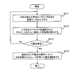
- FIG. 3 is a flowchart showing an operation example of the verification system of this embodiment.
- the surrogate model construction unit 30 constructs a surrogate model that simulates the behavior of the analysis target using the analysis target operation data as learning data (step S11).
- the surrogate model selection unit 60 selects, from the operation data to be analyzed, a surrogate model judged to best reproduce the behavior of the analysis object based on the operation data corresponding to the verification details under the specified conditions (step S12). .
- the verification unit 170 verifies the analysis target using the selected surrogate model (step S13).
- FIG. 4 is a flowchart showing an operation example of the verification unit 170 of this embodiment.
- the operation verification unit 171 inputs operation data including parameters used when operating the analysis object, applies the input parameters to the selected surrogate model, and calculates an evaluation value (step S111).
- the operation verification unit 171 determines whether or not a predetermined condition is satisfied (step S112). If the condition is not satisfied (No in step S112), the operation verification unit 171 repeats the process of step S111.
- step S112 the operation verification unit 171 identifies the optimum parameter as the verification result based on the calculated evaluation value (step S113).
- the simulator operation unit 172 applies the verification result obtained by the operation verification unit 171 to the simulator to obtain an evaluation value (step S114). After that, the final parameters are determined based on the obtained evaluation values.
- the surrogate model construction unit 30 constructs a surrogate model using the operation data to be analyzed as learning data, and the surrogate model selection unit 60 selects the specified data from the operation data to be analyzed. Under the conditions, select a surrogate model according to the verification content. Then, the verification unit 170 verifies the analysis target using the selected surrogate model. Therefore, the cost required for the verification process using the surrogate model can be reduced.
- the operation verification unit 171 of the verification unit 170 inputs operation data to be analyzed, applies the input operation data to the surrogate model, and calculates an evaluation value. Also, the operation verification unit 171 identifies the optimum parameter as a verification result based on the calculated evaluation value. Then, the simulator operation unit 172 applies the verification result obtained by the operation verification unit 171 to the simulator to be analyzed to obtain the operation result. Therefore, it is possible to obtain a more accurate output value while reducing the cost required for the verification process.
- FIG. 5 is a block diagram showing a configuration example of a second embodiment of the verification system according to the present invention.
- the verification system 200 of the present embodiment includes a data acquisition unit 10, a data storage unit 20, a surrogate model construction unit 30, a surrogate model storage unit 40, a surrogate model evaluation unit 50, a surrogate model selection unit 61, a verification a portion 270;
- the configuration of the verification system 200 of this embodiment is different from the configuration of the first embodiment illustrated in FIG. is provided with a verification unit 270.
- Other configurations are the same as those of the first embodiment.
- the surrogate model selection unit 61 receives input of analysis target data and selects a surrogate model highly relevant to the analysis target. It should be noted that the surrogate model selection unit 61 of the present embodiment receives input of data at the time of failure occurrence as data to be analyzed. The method of selecting a surrogate model highly relevant to the analysis target is the same as in the first embodiment.
- the surrogate model building unit 30 builds a surrogate model in a manner that can reproduce the original simulation to some extent.
- the surrogate model simulates the behavior of the subject of analysis, if the accuracy of the surrogate model is high, it is possible to reproduce the situation at the time of the failure even if there is no direct data at the time of the failure. be done.
- the surrogate model selection unit 61 may select a plurality of surrogate models highly relevant to the analysis target.
- the surrogate model selected here may be a unit-based surrogate model or a domain-based surrogate model.
- the surrogate model selection unit 61 may cause the verification unit 270, which will be described later, to perform verification using a plurality of surrogate models.
- FIG. 6 is a block diagram showing a configuration example of the verification unit 270 of this embodiment.
- the verification unit 270 of this embodiment includes a defect reproducing unit 271 and a defect estimating unit 272 .
- the problem reproducing unit 271 reproduces the problem situation to be analyzed using the selected surrogate model. Specifically, the defect reproduction unit 271 inputs data at the time of the defect occurrence including the parameters when the defect occurred in the analysis object, applies the input parameters to the selected surrogate model, and calculates the evaluation value. do.
- the evaluation value calculated by the defect reproduction unit 271 may also be referred to as the first evaluation value. Note that when a plurality of surrogate models are selected, the defect reproduction unit 271 calculates an evaluation value based on each surrogate model.
- the fault estimating unit 272 applies the normal data to the surrogate model used by the fault reproducing unit 271 to reproduce the fault situation, and calculates the normal evaluation value.
- the evaluation value calculated using normal data may be referred to as a second evaluation value.
- the defect estimation unit 272 compares the evaluation value calculated from the data when the defect occurred and the evaluation value calculated from the data when the defect occurred, and estimates the location where the defect occurred.
- Normal data is data that matches or is close to the operating data (driving data) items, and that no abnormality has occurred (it is not judged to be abnormal). predetermined. Further, the method of estimating the defect occurrence location is arbitrary, and the defect estimation unit 272 may estimate the defect occurrence location, for example, based on whether the difference between the two evaluation values is within a predetermined range.
- the defect estimating unit 272 may compare the evaluation values calculated from the surrogate models to estimate the location of the defect.
- the data acquisition unit 10, the surrogate model construction unit 30, the surrogate model evaluation unit 50, the surrogate model selection unit 61, and the verification unit 270 (more specifically, the defect reproduction unit 271 and the defect estimation unit 272) , is implemented by a computer processor that operates according to a program (verification program).
- the operation of the verification system 200 of this embodiment is the same as the operation shown in the flowchart illustrated in FIG. More specifically, the surrogate model selection unit 61 of the present embodiment accepts input of data at the time of failure occurrence as data to be analyzed. Then, the verification unit 270 verifies the analysis target using the selected surrogate model.
- FIG. 7 is a flowchart showing an operation example of the verification unit 270 of this embodiment.
- the defect reproduction unit 271 inputs data at the time of defect occurrence including parameters when the defect occurred in the analysis object (step S211). Then, the defect reproduction unit 271 applies the input parameters to the selected surrogate model to calculate a first evaluation value (step S212).
- the failure estimation unit 272 applies the normal data to the surrogate model to calculate a second evaluation value (step S213). Then, the defect estimator 272 compares the first evaluation value and the second evaluation value to estimate the defect occurrence location (step S214).
- the defect reproduction unit 271 of the verification unit 270 inputs parameters at the time of defect occurrence, applies the input parameters to the selected surrogate model, and calculates the first evaluation value. do. Then, the fault estimating unit 272 applies the normal data to the surrogate model to calculate the second evaluation value, compares the first evaluation value and the second evaluation value, and estimates the fault occurrence location. do. Therefore, since it is possible to easily reproduce the failure occurrence situation and isolate the cause, the cost required for the verification process can be reduced.
- HILS Hard-In-the-Loop-Simulation
- surrogate models generated for each domain can be used, so it is easy to verify in which domain a problem has occurred.
- Embodiment 3 Next, a third embodiment of the verification system of the present invention will be described.
- the third embodiment shows a configuration in which the verification system of the present invention is used for operation verification of an analysis target (in particular, unit basis).
- each unit of an automobile is manufactured by Tier 1. Even if the specifications of these units such as input and output are known, the inside is often black boxed.
- verifying the operation of delivered parts it is necessary to confirm whether they operate according to specifications and whether there are any problems that occur in special cases. In such a case, it is possible to use a simulator, but there is a problem that the method of verifying the operation only by the simulator takes a lot of time. Therefore, by using the verification system of this embodiment, the operation verification can be easily performed.
- FIG. 8 is a block diagram showing a configuration example of the third embodiment of the verification system according to the present invention.
- the verification system 300 of the present embodiment includes a data acquisition unit 10, a data storage unit 20, a surrogate model construction unit 30, a surrogate model storage unit 40, a surrogate model evaluation unit 50, a surrogate model selection unit 62, a verification 370.
- the configuration of the verification system 300 of this embodiment is different from the configuration of the first embodiment illustrated in FIG. differs in that a verification unit 370 is provided in .
- Other configurations are the same as those of the second embodiment.
- the surrogate model selection unit 62 receives input of analysis target data and selects a surrogate model highly relevant to the analysis target. It should be noted that the surrogate model selection unit 62 of the present embodiment receives an input of operation data for each unit as data to be analyzed. The method of selecting a surrogate model highly relevant to the analysis target is the same as in the first embodiment. In particular, in this embodiment, a unit-wise surrogate model is selected.
- the output device 70 may visualize a combination of surrogate models of each unit used for verification.
- FIG. 9 is an explanatory diagram showing an example of visualizing the surrogate model of each unit.
- FIG. 9 exemplifies a combination of surrogate models assuming a power train portion of an automobile. As illustrated in FIG. 9, the output device 70 may associate and visualize related units (or domains).
- the output device 70 may accept designation of a surrogate model used for verification by the designer from a combination of visualized surrogate models.
- the example shown in FIG. 9 indicates that the surrogate model for evaluating the engine temperature has been selected from among the surrogate models of the engine.
- the surrogate model selection unit 62 may specify the surrogate model selected from the output device 70 as the surrogate model used for verification by the verification unit 370, which will be described later.
- FIG. 10 is a block diagram showing a configuration example of the verification unit 370 of this embodiment.
- the verification unit 370 of this embodiment includes an operation verification unit 371 and a simulator operation verification unit 372 .
- the operation verification unit 371 uses the selected surrogate model to verify the operation of the analysis target. Specifically, the operation verification unit 371 inputs evaluation data including normal parameters to be analyzed, applies the input parameters to the selected surrogate model, and calculates an evaluation value. Then, the operation verification unit 371 compares the calculated evaluation value with the evaluation value assumed in the evaluation data, and verifies whether or not a problem has occurred.
- Any method can be used to determine whether or not a defect has occurred. For example, a method similar to the method for estimating a defect by the defect estimation unit 272 of the second embodiment (whether the difference between the two evaluation values is within a predetermined range , etc.) may be used.
- the simulator operation verification unit 372 When it is estimated that a defect will occur based on the evaluation value, the simulator operation verification unit 372 performs operation verification using a simulator for the estimated defect location. Note that the simulator is prepared in advance according to the analysis target. Any method may be used for the simulator operation verification unit 372 to verify the operation. For example, the simulator operation verification unit 372 may obtain an operation result by applying parameters used when it is estimated that a problem will occur to the simulator. Also, the simulator operation verification unit 372 may obtain an operation result based on the parameters instructed by the designer according to the location of the estimated defect.
- a data acquisition unit 10 a surrogate model construction unit 30, a surrogate model evaluation unit 50, a surrogate model selection unit 62, and a verification unit 370 (more specifically, an operation verification unit 371 and a simulator operation verification unit 372) is implemented by a computer processor that operates according to a program (verification program).
- the operation of the verification system 300 of this embodiment is the same as the operation shown in the flowchart illustrated in FIG. More specifically, the surrogate model selection unit 62 of the present embodiment receives an input of operation data for each unit as data to be analyzed. Then, the verification unit 370 verifies each unit to be analyzed using the selected surrogate model.
- FIG. 11 is a flowchart showing an operation example of the verification unit 370 of this embodiment.
- the operation verification unit 371 inputs evaluation data including normal parameters to be analyzed (step S311).
- the operation verification unit 371 then applies the input parameters to the selected surrogate model to calculate an evaluation value (step S312).
- the operation verification unit 371 estimates whether or not a problem has occurred based on the evaluation value (step S313).
- step S313 If it is estimated that no problem has occurred (No in step S313), the processes after step S311 are repeated. On the other hand, if it is estimated that a problem has occurred (Yes in step S313), the simulator operation verification unit 372 performs operation verification on the estimated problem location using the simulator to be analyzed (step S314).
- the operation verification unit 371 of the verification unit 370 inputs evaluation data including normal parameters to be analyzed, and applies the input parameters to the selected surrogate model for evaluation. Calculate the value. Then, when it is estimated that a defect will occur based on the evaluation value, the simulator operation verification unit 372 performs operation verification using the simulator to be analyzed for the estimated defect location. Therefore, since the operation verification can be performed simply, the cost required for the verification process can be reduced.
- the verification unit 370 of the present embodiment verifies normal data at high speed using a surrogate model, and when it is estimated that a problem will occur, verifies a more detailed operating situation using a simulator. In this way, the cost required for the verification process can be reduced because the simulator is used only for verification that requires higher accuracy.
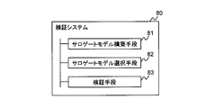
- FIG. 12 is a block diagram showing an overview of a verification system according to the invention.
- a verification system 80 (for example, verification system 100) according to the present invention uses operation data (for example, running data) of an analysis target (for example, automobile) as learning data to construct a surrogate model that simulates the behavior of the analysis target.
- the surrogate model construction means 81 (for example, the surrogate model construction unit 30) and the operation data of the analysis object are determined to reproduce the behavior of the analysis object by the operation data corresponding to the verification content under the specified conditions.
- surrogate model selection means 82 (surrogate model selection unit 60) for selecting a surrogate model to be used, and verification means 83 (for example, verification unit 170) for verifying the analysis object using the selected surrogate model.
- the surrogate model construction means 81 may construct a surrogate model for each domain grouping units, which are the minimum units of verification.
- the surrogate model construction means 81 (for example, in the case of an automobile) creates a surrogate model for each domain grouping units for each function of the automobile (for example, a control system, a body system, a safety system, an information system, etc.). may be constructed.
- the verification means 83 (for example, the verification unit 170) inputs operation data including parameters used when operating the analysis target, applies the input parameters to the selected surrogate model, and calculates an evaluation value. Then, based on the calculated evaluation value, an operation verification means (for example, an operation verification unit 171) that specifies the optimum parameter as a verification result, and the obtained verification result is applied to the simulator to be analyzed to obtain the operation result.
- simulator operating means for example, the simulator operating unit 172 for obtaining
- the verification means 83 (for example, the verification unit 270) inputs the data at the time of failure occurrence including the parameters when the failure occurred in the analysis object, applies the input parameters to the selected surrogate model, and applies the A defect reproducing means (for example, a defect reproducing unit 271) that calculates one evaluation value, and a second evaluation value is calculated by applying normal data to the surrogate model, and the first evaluation value and the second evaluation value are calculated. It may also include defect estimating means (for example, defect estimating section 272) for estimating a defect occurrence location by comparing the evaluation value.
- the verification means 83 (for example, the verification unit 370) inputs evaluation data including the parameters of the normal state of the analysis target, applies the input parameters to the selected surrogate model, and calculates an evaluation value.
- means for example, operation verification unit 371
- simulator operation verification means for example, , simulator operation verification unit 372.
- the surrogate model selection means 82 may select a surrogate model in which the data item to be analyzed and the input/output data item match.
- Appendix 2 The verification system according to Appendix 1, wherein the surrogate model building means builds a surrogate model in units of domains in which units, which are minimum verification units, are put together.
- appendix 3 The verification system according to appendix 1 or appendix 2, wherein the surrogate model construction means constructs a surrogate model in units of domains in which units are organized for each function of the automobile.
- the verification means is Input the operation data including the parameters used when operating the analysis target, apply the input parameters to the selected surrogate model to calculate the evaluation value, and based on the calculated evaluation value, determine the optimal parameter as a verification result;
- the verification system according to any one of Appendices 1 to 3, including a simulator operating means for applying the obtained verification result to a simulator to be analyzed to obtain an operation result.
- the verification means is a defect reproducing means for inputting data at the time of defect occurrence including parameters when the defect occurred in the analysis target, applying the input parameters to the selected surrogate model, and calculating a first evaluation value; Defect estimating means for applying normal data to the surrogate model to calculate a second evaluation value, comparing the first evaluation value and the second evaluation value, and estimating a defect occurrence location and the verification system of any one of Clauses 1-3.
- the verification means is an operation verification means for inputting evaluation data including parameters of a normal state to be analyzed and applying the input parameters to a selected surrogate model to calculate an evaluation value; simulator operation verification means for performing operation verification using the simulator to be analyzed for the estimated defect location when it is estimated that a defect will occur based on the evaluation value.
- a verification system according to any one of the preceding claims.
- Appendix 7 The verification system according to any one of Appendices 1 to 6, wherein the surrogate model selection means selects a surrogate model in which the data item to be analyzed and the input/output data item match.
- a surrogate model building process for building a surrogate model that simulates the behavior of the analysis target using the operation data of the analysis target as learning data
- a surrogate model selection process for selecting the surrogate model that is determined to reproduce the behavior of the analysis target according to the operation data according to the verification content most closely under specified conditions from the analysis target operation data
- a program storage medium for storing a verification program for executing a verification process for verifying an analysis target using the selected surrogate model.
- the program storage medium which stores a verification program for constructing a surrogate model in units of domains in which units, which are minimum verification units, are grouped together in the surrogate model construction processing.
- a surrogate model building process for building a surrogate model that simulates the behavior of the analysis target using the operation data of the analysis target as learning data
- a surrogate model selection process for selecting the surrogate model that is determined to reproduce the behavior of the analysis target according to the operation data according to the verification content most closely under specified conditions from the analysis target operation data
- a verification program for executing verification processing for verifying an analysis target using the selected surrogate model.
- a surrogate model storage means for storing a surrogate model that simulates the behavior of the analysis target, constructed using the operation data of the analysis target as learning data; a surrogate model selection means for selecting, from the operation data to be analyzed, the surrogate model that is judged to reproduce the behavior of the analysis object most accurately based on the operation data according to the verification content under specified conditions;
- a verification device comprising verification means for verifying an analysis target using the selected surrogate model.
Landscapes
- Engineering & Computer Science (AREA)
- Physics & Mathematics (AREA)
- Theoretical Computer Science (AREA)
- Evolutionary Computation (AREA)
- Geometry (AREA)
- General Physics & Mathematics (AREA)
- General Engineering & Computer Science (AREA)
- Computer Hardware Design (AREA)
- Medical Informatics (AREA)
- Software Systems (AREA)
- Computer Vision & Pattern Recognition (AREA)
- Artificial Intelligence (AREA)
- Automation & Control Theory (AREA)
- Aviation & Aerospace Engineering (AREA)
- Computational Mathematics (AREA)
- Mathematical Analysis (AREA)
- Mathematical Optimization (AREA)
- Pure & Applied Mathematics (AREA)
- Management, Administration, Business Operations System, And Electronic Commerce (AREA)
Abstract
Description
図1は、本発明による検証システムの第一の実施形態の構成例を示すブロック図である。本実施形態の検証システム100は、サロゲートモデルを用いて、分析対象の検証を行うシステムである。上述するサロゲートモデルは近似解の絞り込みが可能なモデルと言えるため、本実施形態の検証システム100は、近似解の絞り込みが可能なサロゲートモデルを用いて検証を行うシステムと言える。
次に、本発明の検証システムの第二の実施形態を説明する。第二の実施形態では、本発明の検証システムが分析対象の不具合検証に用いられる場合の構成を示す。図5は、本発明による検証システムの第二の実施形態の構成例を示すブロック図である。
次に、本発明の検証システムの第三の実施形態を説明する。第三の実施形態では、本発明の検証システムが分析対象(特に、ユニット単位)の動作検証に用いられる場合の構成を示す。
分析対象の稼動データから、指定された条件のもと、検証内容に応じた当該稼動データによる分析対象の挙動を最も再現すると判断される前記サロゲートモデルを選択するサロゲートモデル選択手段と、
選択された前記サロゲートモデルを用いて分析対象の検証を行う検証手段とを備えた
ことを特徴とする検証システム。
付記1記載の検証システム。
付記1または付記2記載の検証システム。
分析対象を稼動させる際に用いられるパラメータを含む稼動データを入力し、入力されたパラメータを選択されたサロゲートモデルに適用して評価値を算出し、算出された評価値に基づいて、最適なパラメータを検証結果として特定する動作検証手段と、
得られた検証結果を、分析対象のシミュレータに適用して動作結果を得るシミュレータ動作手段とを含む
付記1から付記3のうちのいずれか1つに記載の検証システム。
分析対象に不具合が発生した際のパラメータを含む不具合発生時のデータを入力し、入力されたパラメータを選択されたサロゲートモデルに適用して第一の評価値を算出する不具合再現手段と、
前記サロゲートモデルに正常時のデータを適用して第二の評価値を算出し、前記第一の評価値と、前記第二の評価値とを比較して、不具合発生個所を推定する不具合推定手段とを含む
付記1から付記3のうちのいずれか1つに記載の検証システム。
分析対象の正常時のパラメータを含む評価データを入力し、入力されたパラメータを選択されたサロゲートモデルに適用して評価値を算出する動作検証手段と、
前記評価値に基づいて不具合が発生すると推定された場合、推定された不具合の個所について、前記分析対象のシミュレータを用いた動作検証を行うシミュレータ動作検証手段とを含む
付記1から付記3のうちのいずれか1つに記載の検証システム。
付記1から付記6のうちのいずれか1つに記載の検証システム。
分析対象の稼動データから、指定された条件のもと、検証内容に応じた当該稼動データによる分析対象の挙動を最も再現すると判断される前記サロゲートモデルを選択し、
選択された前記サロゲートモデルを用いて分析対象の検証を行う
ことを特徴とする検証方法。
付記8記載の検証方法。
分析対象の稼動データを学習データとして用いて、当該分析対象の挙動を模擬するサロゲートモデルを構築するサロゲートモデル構築処理、
分析対象の稼動データから、指定された条件のもと、検証内容に応じた当該稼動データによる分析対象の挙動を最も再現すると判断される前記サロゲートモデルを選択するサロゲートモデル選択処理、および、
選択された前記サロゲートモデルを用いて分析対象の検証を行う検証処理
を実行させるための検証プログラムを記憶するプログラム記憶媒体。
サロゲートモデル構築処理で、検証の最小単位であるユニットをまとめたドメイン単位でサロゲートモデルを構築させる検証プログラムを記憶する
付記10記載のプログラム記憶媒体。
分析対象の稼動データを学習データとして用いて、当該分析対象の挙動を模擬するサロゲートモデルを構築するサロゲートモデル構築処理、
分析対象の稼動データから、指定された条件のもと、検証内容に応じた当該稼動データによる分析対象の挙動を最も再現すると判断される前記サロゲートモデルを選択するサロゲートモデル選択処理、および、
選択された前記サロゲートモデルを用いて分析対象の検証を行う検証処理
を実行させるための検証プログラム。
サロゲートモデル構築処理で、検証の最小単位であるユニットをまとめたドメイン単位でサロゲートモデルを構築させる
付記12記載の検証プログラム。
分析対象の稼動データから、指定された条件のもと、検証内容に応じた当該稼動データによる分析対象の挙動を最も再現すると判断される前記サロゲートモデルを選択するサロゲートモデル選択手段と、
選択された前記サロゲートモデルを用いて分析対象の検証を行う検証手段を備えた
ことを特徴とする検証装置。
20 データ記憶部
30 サロゲートモデル構築部
40 サロゲートモデル記憶部
50 サロゲートモデル評価部
60,61,62 サロゲートモデル選択部
70 出力装置
170,270,370 検証部
171 動作検証部
172 シミュレータ動作部
271 不具合再現部
272 不具合推定部
371 動作検証部
372 シミュレータ動作検証部
100,200,300 検証システム
Claims (11)
- 分析対象の稼動データを学習データとして用いて、当該分析対象の挙動を模擬するサロゲートモデルを構築するサロゲートモデル構築手段と、
分析対象の稼動データから、指定された条件のもと、検証内容に応じた当該稼動データによる分析対象の挙動を最も再現すると判断される前記サロゲートモデルを選択するサロゲートモデル選択手段と、
選択された前記サロゲートモデルを用いて分析対象の検証を行う検証手段とを備えた
ことを特徴とする検証システム。 - サロゲートモデル構築手段は、検証の最小単位であるユニットをまとめたドメイン単位でサロゲートモデルを構築する
請求項1記載の検証システム。 - サロゲートモデル構築手段は、自動車の機能ごとにユニットをまとめたドメイン単位でサロゲートモデルを構築する
請求項1または請求項2記載の検証システム。 - 検証手段は、
分析対象を稼動させる際に用いられるパラメータを含む稼動データを入力し、入力されたパラメータを選択されたサロゲートモデルに適用して評価値を算出し、算出された評価値に基づいて、最適なパラメータを検証結果として特定する動作検証手段と、
得られた検証結果を、分析対象のシミュレータに適用して動作結果を得るシミュレータ動作手段とを含む
請求項1から請求項3のうちのいずれか1項に記載の検証システム。 - 検証手段は、
分析対象に不具合が発生した際のパラメータを含む不具合発生時のデータを入力し、入力されたパラメータを選択されたサロゲートモデルに適用して第一の評価値を算出する不具合再現手段と、
前記サロゲートモデルに正常時のデータを適用して第二の評価値を算出し、前記第一の評価値と、前記第二の評価値とを比較して、不具合発生個所を推定する不具合推定手段とを含む
請求項1から請求項3のうちのいずれか1項に記載の検証システム。 - 検証手段は、
分析対象の正常時のパラメータを含む評価データを入力し、入力されたパラメータを選択されたサロゲートモデルに適用して評価値を算出する動作検証手段と、
前記評価値に基づいて不具合が発生すると推定された場合、推定された不具合の個所について、前記分析対象のシミュレータを用いた動作検証を行うシミュレータ動作検証手段とを含む
請求項1から請求項3のうちのいずれか1項に記載の検証システム。 - サロゲートモデル選択手段は、分析対象のデータ項目と入出力データ項目とが一致するサロゲートモデルを選択する
請求項1から請求項6のうちのいずれか1項に記載の検証システム。 - 分析対象の稼動データを学習データとして用いて、当該分析対象の挙動を模擬するサロゲートモデルを構築し、
分析対象の稼動データから、指定された条件のもと、検証内容に応じた当該稼動データによる分析対象の挙動を最も再現すると判断される前記サロゲートモデルを選択し、
選択された前記サロゲートモデルを用いて分析対象の検証を行う
ことを特徴とする検証方法。 - 検証の最小単位であるユニットをまとめたドメイン単位でサロゲートモデルを構築する
請求項8記載の検証方法。 - コンピュータに、
分析対象の稼動データを学習データとして用いて、当該分析対象の挙動を模擬するサロゲートモデルを構築するサロゲートモデル構築処理、
分析対象の稼動データから、指定された条件のもと、検証内容に応じた当該稼動データによる分析対象の挙動を最も再現すると判断される前記サロゲートモデルを選択するサロゲートモデル選択処理、および、
選択された前記サロゲートモデルを用いて分析対象の検証を行う検証処理
を実行させるための検証プログラムを記憶するプログラム記憶媒体。 - コンピュータに、
サロゲートモデル構築処理で、検証の最小単位であるユニットをまとめたドメイン単位でサロゲートモデルを構築させる検証プログラムを記憶する
請求項10記載のプログラム記憶媒体。
Priority Applications (3)
| Application Number | Priority Date | Filing Date | Title |
|---|---|---|---|
| JP2022581108A JPWO2022172392A1 (ja) | 2021-02-12 | 2021-02-12 | |
| PCT/JP2021/005213 WO2022172392A1 (ja) | 2021-02-12 | 2021-02-12 | 検証システム、検証方法および検証プログラム |
| US18/275,560 US20240104273A1 (en) | 2021-02-12 | 2021-02-12 | Verification system, verification method, and verification program |
Applications Claiming Priority (1)
| Application Number | Priority Date | Filing Date | Title |
|---|---|---|---|
| PCT/JP2021/005213 WO2022172392A1 (ja) | 2021-02-12 | 2021-02-12 | 検証システム、検証方法および検証プログラム |
Publications (1)
| Publication Number | Publication Date |
|---|---|
| WO2022172392A1 true WO2022172392A1 (ja) | 2022-08-18 |
Family
ID=82838542
Family Applications (1)
| Application Number | Title | Priority Date | Filing Date |
|---|---|---|---|
| PCT/JP2021/005213 WO2022172392A1 (ja) | 2021-02-12 | 2021-02-12 | 検証システム、検証方法および検証プログラム |
Country Status (3)
| Country | Link |
|---|---|
| US (1) | US20240104273A1 (ja) |
| JP (1) | JPWO2022172392A1 (ja) |
| WO (1) | WO2022172392A1 (ja) |
Citations (3)
| Publication number | Priority date | Publication date | Assignee | Title |
|---|---|---|---|---|
| US6760693B1 (en) * | 2000-03-29 | 2004-07-06 | Ford Global Technologies, Llc | Method of integrating computer visualization for the design of a vehicle |
| US6850921B1 (en) * | 2000-11-02 | 2005-02-01 | Ford Global Technologies, Llc | Method for cascading vehicle system targets to component level design objectives |
| JP2016146169A (ja) * | 2014-12-18 | 2016-08-12 | ダッソー システムズ シムリア コーポレイション | データに基づくインタラクティブ3dエクスペリエンス |
-
2021
- 2021-02-12 US US18/275,560 patent/US20240104273A1/en active Pending
- 2021-02-12 JP JP2022581108A patent/JPWO2022172392A1/ja active Pending
- 2021-02-12 WO PCT/JP2021/005213 patent/WO2022172392A1/ja active Application Filing
Patent Citations (3)
| Publication number | Priority date | Publication date | Assignee | Title |
|---|---|---|---|---|
| US6760693B1 (en) * | 2000-03-29 | 2004-07-06 | Ford Global Technologies, Llc | Method of integrating computer visualization for the design of a vehicle |
| US6850921B1 (en) * | 2000-11-02 | 2005-02-01 | Ford Global Technologies, Llc | Method for cascading vehicle system targets to component level design objectives |
| JP2016146169A (ja) * | 2014-12-18 | 2016-08-12 | ダッソー システムズ シムリア コーポレイション | データに基づくインタラクティブ3dエクスペリエンス |
Also Published As
| Publication number | Publication date |
|---|---|
| US20240104273A1 (en) | 2024-03-28 |
| JPWO2022172392A1 (ja) | 2022-08-18 |
Similar Documents
| Publication | Publication Date | Title |
|---|---|---|
| US10816978B1 (en) | Automated vehicle artificial intelligence training based on simulations | |
| US7991583B2 (en) | Diagnosis in automotive applications | |
| JP7053147B2 (ja) | 自動車特に自動車の装置のエネルギー効率を分析するためのシステムおよび方法 | |
| JP2017522212A (ja) | 車両のエネルギー効率を分析するためのシステムおよび方法 | |
| US20170050590A1 (en) | System for assessing and/or optimising the operating behaviour | |
| US20160025025A1 (en) | Method for optimizing vehicles and engines used for driving such vehicles | |
| Lamberg et al. | Model-based testing of embedded automotive software using MTest | |
| Tatar | Enhancing ADAS test and validation with automated search for critical situations | |
| CN107783529B (zh) | 用于验证执行器控制数据的方法 | |
| King et al. | A taxonomy and survey on validation approaches for automated driving systems | |
| US6101432A (en) | Vehicle rattle detection method and system | |
| US8751094B2 (en) | Method for validation of a graphically based executable control specification using model extraction | |
| Eisele et al. | ADAS virtual prototyping with the OpenMETA toolchain | |
| WO2022172392A1 (ja) | 検証システム、検証方法および検証プログラム | |
| Hilf et al. | Automated simulation of scenarios to guide the development of a crosswind stabilization function | |
| JP2007507765A (ja) | 車両用の制御プロセスをテストするシステムおよび方法 | |
| Wehner et al. | Development of driver assistance systems using virtual hardware-in-the-loop | |
| Zander-Nowicka et al. | Automotive validation functions for on-line test evaluation of hybrid real-time systems | |
| Koller et al. | Implementation of vehicle simulation model in a modern dynamometer test environment | |
| Lauber et al. | Virtual test method for complex and variant-rich automotive systems | |
| CN113590458A (zh) | 用于检查技术系统的方法和设备 | |
| CN113704085A (zh) | 用于检查技术系统的方法和设备 | |
| Neubauer et al. | Model-based development and simulative verification of logical vehicle functions using executable UN/ECE regulations | |
| KR20210023722A (ko) | 요구 사항에 대한 시스템의 테스트 방법 | |
| Altinger | State-of-the-art tools and methods used in the automotive industry |
Legal Events
| Date | Code | Title | Description |
|---|---|---|---|
| 121 | Ep: the epo has been informed by wipo that ep was designated in this application |
Ref document number: 21925645 Country of ref document: EP Kind code of ref document: A1 |
|
| ENP | Entry into the national phase |
Ref document number: 2022581108 Country of ref document: JP Kind code of ref document: A |
|
| WWE | Wipo information: entry into national phase |
Ref document number: 18275560 Country of ref document: US |
|
| NENP | Non-entry into the national phase |
Ref country code: DE |
|
| 122 | Ep: pct application non-entry in european phase |
Ref document number: 21925645 Country of ref document: EP Kind code of ref document: A1 |