WO2022168841A1 - 端子 - Google Patents
端子 Download PDFInfo
- Publication number
- WO2022168841A1 WO2022168841A1 PCT/JP2022/003889 JP2022003889W WO2022168841A1 WO 2022168841 A1 WO2022168841 A1 WO 2022168841A1 JP 2022003889 W JP2022003889 W JP 2022003889W WO 2022168841 A1 WO2022168841 A1 WO 2022168841A1
- Authority
- WO
- WIPO (PCT)
- Prior art keywords
- terminal
- leg
- contact
- contact portion
- protection
- Prior art date
- Legal status (The legal status is an assumption and is not a legal conclusion. Google has not performed a legal analysis and makes no representation as to the accuracy of the status listed.)
- Ceased
Links
Images










Classifications
-
- H—ELECTRICITY
- H01—ELECTRIC ELEMENTS
- H01R—ELECTRICALLY-CONDUCTIVE CONNECTIONS; STRUCTURAL ASSOCIATIONS OF A PLURALITY OF MUTUALLY-INSULATED ELECTRICAL CONNECTING ELEMENTS; COUPLING DEVICES; CURRENT COLLECTORS
- H01R13/00—Details of coupling devices of the kinds covered by groups H01R12/70 or H01R24/00 - H01R33/00
- H01R13/02—Contact members
- H01R13/10—Sockets for co-operation with pins or blades
-
- H—ELECTRICITY
- H01—ELECTRIC ELEMENTS
- H01R—ELECTRICALLY-CONDUCTIVE CONNECTIONS; STRUCTURAL ASSOCIATIONS OF A PLURALITY OF MUTUALLY-INSULATED ELECTRICAL CONNECTING ELEMENTS; COUPLING DEVICES; CURRENT COLLECTORS
- H01R13/00—Details of coupling devices of the kinds covered by groups H01R12/70 or H01R24/00 - H01R33/00
- H01R13/02—Contact members
- H01R13/10—Sockets for co-operation with pins or blades
- H01R13/11—Resilient sockets
Definitions
- the present disclosure relates to terminals provided for electrical connection. Specifically, the present disclosure relates to terminals (more specifically, receptacle terminals, for example) having mating portions for mating with other terminals.
- Patent Document 1 discloses a receptacle terminal using a contact spring.
- a protection member (specifically, a protection flap 56) is provided at the opening of the part (see FIG. 6 of Patent Document 1).
- a protective portion 103 having a simple standing wall-like structure (that is, a standing wall structure extending only in the transverse direction of the terminal) is provided in the opening as a protective member (FIG. 15 (D ) and FIG. 15(F)).
- FIG. 15(A) is a top view of the fitting portion of the conventional terminal 100.
- FIG. FIG. 15B is a side view of one of the fitting portions of the conventional terminal 100.
- FIG. FIG. 15(C) is a cross-sectional view of the fitting portion of the terminal 100 shown in FIG. 15(B) taken along line Y-Y'.
- FIG. 15(D) is a cross-sectional view of the fitting portion of the terminal 100 shown in FIG. 15(A) taken along the line XX'.
- FIG. 15E is a perspective view of the terminal 100 viewed from the side of the rear end portion 104 opposite to the opening of the fitting portion.
- FIG. 15F is a perspective view of the fitting portion of the terminal 100 viewed from the opening side (the front side of the terminal).
- another metal plate-shaped terminal 105 can be inserted into the fitting portion of the conventional terminal 100 (see FIGS. 16 and 17).
- the protection portion 103 can guide the other terminal 105 to the inside of the fitting portion, especially the contact portion 102 . This can reduce inappropriate contact (for example, so-called “thud” or "interference") between the tip portion 106 of the other terminal 105 and the contact portion 102 of the elastic member 101.
- the protection portion 103 can protect the contact portion 102 from damage or the like. By doing so, for example, when another terminal 105 is inserted into the fitting portion of the conventional terminal 100 (fitting state) as shown in FIG. can be physically and electrically contacted to form a contact point 102p.
- the tip portion 102t of the contact portion 102 located at the free end of the elastic member 101 is pushed down below the tip portion 103t of the protection portion 103. As shown in FIG. As a result, the contact portion 102 can elastically press the other terminal 105 from below.
- a plated layer is provided on the terminal 100 . More specifically, a plated layer is provided on the surface of the terminal 100 .
- the contact portion 102 and other terminals 105 may be provided with a plating layer from the viewpoint of imparting conductivity and/or rust resistance.
- terminals may not be handled as desired.
- terminals may be abused.
- FIGS. 18 and 19 it must be assumed that another terminal 105 is undesirably inserted obliquely into the fitting portion of the conventional terminal 100 (see FIG. 18(B)). In other words, it must be assumed that the terminal is inserted so as to form an angle with respect to the axial direction of the terminal.
- the tip portion 106 of the other terminal 105 and the tip portion 102t of the contact portion 102 are It has been found that the collision damages the plated layers provided on each of the other terminal 105 and the contact portion 102 and scrapes or reduces them.
- the contact point 102 of the elastic member 101 has an electrical contact point or a portion capable of forming a contact point, especially the plated layer of the contact point 102p (see FIG. 17(D)) is damaged and scraped off or reduced.
- the research of the inventors of the present application has found for the first time that the plating layer can be damaged and scraped or reduced by inserting in an oblique direction. If the plated layer is damaged and scraped or reduced, the resistance value of the terminal may fluctuate, which may lead to concerns that the resistance value of the terminal may become unstable.
- a main object of the present disclosure is to provide a terminal that can further suppress or reduce scraping of the plated layer.
- the inventors of the present application have tried to solve the above problems by dealing with them in a new direction, rather than dealing with them on the extension of the conventional technology. As a result, the present inventors have invented a terminal having a fitting portion that achieves the above main object.
- leg portions branched portions or portions
- leg portions in at least one of the contact portion and the protection portion in a terminal having a fitting portion.
- legs are sometimes called “claws” or “fingers” because of their shape).
- FIGS. better disperses and reduces impact forces and/or pressures that may occur in contact with other terminals, even if the terminal is inserted into the mating at an angle, and It has been found that the other terminal can be introduced more successfully and smoothly into the terminal (see FIGS. 5 and 12).
- the contact portion and the protection portion with two or more branched legs, even if another terminal is inserted into the fitting portion from an undesired oblique direction. Even if there is, the force can be distributed so that the pressure is not concentrated and/or excessive on the contact portion and/or the protective portion (see FIG. 5(D), FIG. 12(D)).
- the present disclosure provides a terminal having a fitting portion, wherein the fitting portion has a contact portion and a protection portion, and the contact portion contacts with another terminal that can be accommodated in the fitting portion. a portion including a point, the protection portion is provided in an opening (or an opening end) of the fitting portion, and the contact portion and the protection portion are positioned so as to face each other; At least one of the contact portion and the protection portion has two or more branched legs.
- terminals described above may be referred to as "terminals of the present disclosure” or simply "terminals”.
- the present disclosure can provide a terminal that can further suppress or reduce scraping of the plated layer. It should be noted that the effects described in this specification are merely examples and are not limited, and additional effects may be provided.
- FIG. 1 is a schematic diagram schematically showing a fitting portion of a terminal according to an embodiment of the present disclosure (first embodiment).
- FIG. 2 is a schematic top view exemplifying the relationship between the contact portion and the protection portion in the fitting portion of the terminal according to the first embodiment of the present disclosure.
- FIG. 3 is a schematic top view schematically showing the relationship (modification) between the contact portion and the protection portion in the fitting portion of the terminal according to the first embodiment of the present disclosure.
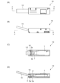
- FIG. 4 is a schematic diagram (before insertion) schematically showing “oblique insertion” of another terminal into the fitting portion of the terminal according to the first embodiment of the present disclosure.
- FIG. 1 is a schematic diagram schematically showing a fitting portion of a terminal according to an embodiment of the present disclosure (first embodiment).
- FIG. 2 is a schematic top view exemplifying the relationship between the contact portion and the protection portion in the fitting portion of the terminal according to the first embodiment of the present disclosure.
- FIG. 3 is a schematic top view schematically showing
- FIG. 5 is a schematic diagram schematically showing “oblique insertion” of another terminal into the fitting portion of the terminal according to the first embodiment of the present disclosure (at the time of insertion).
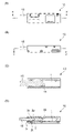
- FIG. 6 is a schematic diagram (before insertion) schematically showing insertion of another terminal into the fitting portion of the terminal according to the first embodiment of the present disclosure;
- FIG. 7 is a schematic diagram schematically showing a state in which another terminal is inserted into the fitting portion of the terminal according to the first embodiment of the present disclosure and coupled to each other (fitting state).
- FIG. 8 is a schematic diagram schematically showing a fitting portion of a terminal according to another embodiment of the present disclosure (second embodiment).
- FIG. 9 is a schematic top view exemplifying the relationship between the contact portion and the protection portion in the fitting portion of the terminal according to the second embodiment of the present disclosure.
- FIG. 10 is a schematic top view schematically showing the relationship (modification) between the contact portion and the protection portion in the fitting portion of the terminal according to the second embodiment of the present disclosure.
- FIG. 11 is a schematic diagram (before insertion) schematically showing “oblique insertion” of another terminal into the fitting portion of the terminal according to the second embodiment of the present disclosure.
- FIG. 12 is a schematic diagram schematically showing “oblique insertion” of another terminal into the fitting portion of the terminal according to the second embodiment of the present disclosure (at the time of insertion).
- FIG. 10 is a schematic top view schematically showing the relationship (modification) between the contact portion and the protection portion in the fitting portion of the terminal according to the second embodiment of the present disclosure.
- FIG. 11 is a schematic diagram (before insertion) schematically showing “oblique insertion” of another terminal into the fitting
- FIG. 13 is a schematic diagram schematically showing insertion of another terminal into the fitting portion of the terminal according to the second embodiment of the present disclosure (before insertion);
- FIG. 14 is a schematic diagram schematically showing a state where another terminal is inserted into the fitting portion of the terminal according to the second embodiment of the present disclosure and coupled to each other (fitting state).
- FIG. 15 is a schematic diagram schematically showing a fitting portion of a conventional terminal (conventional form).
- FIG. 16 is a schematic diagram schematically showing insertion of another terminal into the fitting portion of the conventional terminal (before insertion).
- FIG. 17 is a schematic diagram schematically showing a state in which another terminal is inserted into the fitting portion of the conventional terminal and coupled to each other (fitting state).
- FIG. 18 is a schematic diagram (before insertion) schematically showing "oblique insertion” of another terminal into the fitting portion of the conventional terminal.
- FIG. 19 is a schematic diagram schematically showing "oblique insertion” of another terminal into the fitting portion of the conventional terminal (at the time of insertion).
- a terminal of the present disclosure is a terminal for electrical connection.
- the present disclosure relates to terminals having mating portions for providing electrical connections (hereinafter terminals of the present disclosure may also be referred to as "receptacle terminals" or “female terminals").
- terminals of the present disclosure may also be referred to as "receptacle terminals" or “female terminals”).
- the fitting portion has at least a contact portion and a protection portion (see FIGS. 1 and 8).
- terminal means a part or member that contributes to electrical connection together with other terminals.
- the term "fitting portion” means a portion or site that can receive and accommodate at least a portion of another terminal.
- the terminals of the present disclosure and other terminals may be engaged with or combined with each other, and do not necessarily have to be in a strict manner of being perfectly or closely fitted. Therefore, in short, it can be said that a portion or portion of a terminal that is used for engagement or combination with another terminal is a fitting portion.
- the mating portion is provided with a contact portion that can be brought into physical and/or electrical contact with another terminal to form a point of contact or contact.
- the shape of the fitting portion is not particularly limited as long as it can accommodate at least part of the other terminals.
- it may have a shape such as a box shape or a cylinder shape.
- the shape of the fitting portion is box-shaped, such fitting portion may be referred to as a "box".
- contact portion means a portion or portion comprising a contact point that can be formed by physical and/or electrical contact with another terminal that can be accommodated in the mating portion.
- the “contact portion” is the point of contact between the terminal of the present disclosure and the other terminal (in other words, “direct contact” or “ It corresponds to a terminal portion or terminal part having a portion or portion serving as an electrical contact.
- the contact portion may be provided at or near one end of the metal member used for the terminal.
- the contact portion may be included in a metallic member (for example, a plate-shaped and/or elongated metallic member) provided on the terminal.
- the contact portion may be provided at one end of, for example, a metal elastic member (for example, a plate-shaped and/or elongated metal member).
- the other end of the elastic member or its periphery may be fixed within the fitting.
- the terminal of the present disclosure is a metal member (for example, an elongated metal member or a metal plate-like member; in a preferred embodiment, a metal member or metal plate-like member extending in the longitudinal direction of the terminal).
- a contact portion may be provided at one end corresponding to the free end of the metal member), and the other end of the metal member may be a fixed end.
- One end of such a metal member ie the end having the contact portion on the elastic member, can be moved or displaced as a free end. Therefore, the contact portion can physically contact (for example, directly contact) another terminal and elastically press the other terminal, which contributes to the formation of an electrical contact point (FIGS. 7 and 14). reference).
- the contact portion or the portion of the free end of the elastic member provided with the contact point may be referred to as the contact portion as a whole or comprehensively.
- the elastic member may be plate-shaped as a whole. If the elastic member is generally plate-shaped, the elastic member can be moved or displaced like a spring. That is, such a member may be provided as a leaf spring.
- a plate with a free end at the more proximal or more forward end of the opening side and a fixed end at the more distal or more posterior end of the opening side It may be provided as a spring and a contact portion may be provided at the free end of the leaf spring.
- the elastic member having the contact portion as a leaf spring may have an elongated shape extending along the longitudinal direction of the terminal. Such a plate-like elastic member is sometimes called a "leaf".
- an additional plate-like elastic member may be arranged below or behind the plate-like elastic member having the contact portion (not shown).
- the plate-shaped elastic member having the contact portion is called “main leaf” or “main leaf spring”
- the additional additional elastic member is called “assist leaf” or “assist leaf spring”.
- the shape of the assist leaf (spring) is not particularly limited as long as it can press the main leaf (spring).
- a contact portion is a terminal portion that contributes to contact or abutment with another terminal. That is, the contact portion has a contact point with another terminal (see, for example, the contact point 2p in FIG. 7(D) and the contact point 22p in FIG. 14(D)).
- a portion having such a contact point may be convexly raised.
- the contact point may correspond to a curved or displaced portion of the contact portion (in particular, a curved or displaced portion when viewed in cross section).
- the elastic member may have a shape in which the portion having the contact point is locally curved (curved upward).
- the elastic member has a convex or ridged displaced or curved configuration more upward (or transverse to the opening) at the point of contact. More specifically, such a portion may protrude so as to have a substantially V-shaped, substantially U-shaped, or substantially L-shaped shape in a cross-sectional view in the direction in which the thickness of the contact portion can be seen. Good (see FIGS. 1(D), 8(D) and 15(D)).
- the portion having the contact point may be provided by applying an external force to the metal member provided as the elastic member.
- it may be molded by cutting and pressing a metallic plate material.
- the “protection portion” is a portion or portion that can be provided around the opening of the fitting portion of the terminal of the present disclosure or around it (hereinafter sometimes referred to as “protector”) (FIG. 1 (G ) and FIG. 8(G)).
- the protection portion may be provided by bending or folding back a portion of the terminal portion forming the opening toward the rear of the terminal. It can be said that the protection portion may be provided at the opening end (particularly inside thereof) of the housing of the terminal (the terminal member forming a housing having an elastic member inside).
- Such a protection portion is a portion of the terminal that contributes to protection of at least the contact portion.
- the protection portion in the present disclosure preferably protects the contact portion and guides other terminals to the contact portion.
- the protection portion can reduce adverse effects on the contact portion from, for example, physical collision (“thump” or “interference”) between the contact portion and another terminal due to excessive force or excessive speed.
- the shape of the protection part is not particularly limited as long as it can be provided in or around the opening.
- the protective portion may be provided at the open end of the terminal so as to partially reduce or block the open area formed by the open end. terminal member).
- the protection portion may be positioned close to the opening provided in the fitting portion or its periphery, for example, the contact portion.
- the protection portion may be provided at the opening end of the terminal (the opening of the housing-like member of the terminal) provided with the opening of the terminal.
- the protection portion may have a shape extending from the opening/opening end of the fitting portion, for example, and may extend toward the rear of the bent terminal so as to protrude.
- the protection part is part of the terminal portion forming the opening, that is, part of the opening end, for example, the bottom of the opening end of the terminal (for example, the opening end of the housing of the terminal). portion) bent backwards to form a ridge (see FIGS. 1(G) and 8(G)).
- the protection part may be formed, for example, by cutting, bending, and/or folding a metal plate material.
- the protection portion is formed by cutting and folding back or bending a metallic plate material (see FIGS. 1(H) and 8(H)).
- the protection portion may have a shape in which a member forming the housing of the terminal is partially bent (preferably bent so as to be folded back).
- the member forming the housing of the terminal has a bent shape (preferably bent back toward the rear side of the terminal) so that a portion of the member is folded back at the opening/opening end. good.
- a portion of the terminal housing portion is bent (preferably folded) at the opening/opening end so that the outer surface of the terminal housing portion serves as the protector surface.
- the protection part may have a bent shape).
- the "opening" of the fitting portion refers to a portion or site for receiving another terminal in the fitting portion, and there is no particular limitation on its shape.
- an opening portion or an opening end that contributes to fitting with another member corresponds to the "opening portion”.
- the opening or the opening end of the housing-like member having the elastic member inside can correspond to the "opening”.
- the openings may have complementary shapes (ie, opening shapes) that match the shape of the other terminals.
- the opening may have a substantially rectangular opening shape (see FIGS. 1(G) and 8(G)).
- the opening shape of the opening may be other shapes such as a substantially circular shape.
- substantially rectangular mainly means a quadrilateral shape such as a square and a rectangle, and may be any shape that can be recognized as a quadrilateral at a glance by those skilled in the art. Therefore, its corners may be rounded.
- substantially circular mainly means a circular shape such as a perfect circle or an ellipse, and may be any shape that can be recognized as a circle by a person skilled in the art at first glance.
- shapes such as oval and teardrop can also be included in the substantially circular shape.
- the contact portion and the protection portion may be positioned so as to face each other (see FIGS. 2 and 9).
- the contact portion and the protection portion may be adjacent to each other, preferably side by side along the axial direction of the terminal.
- the protective portion and the contact portion may be provided so as to face each other in the axial direction of the terminal, that is, in the longitudinal direction of the terminal (preferably, the protective portion is located closer to the opening side of the terminal). or more forwardly positioned while the contact portion is positioned more distally or more rearwardly of the opening side of the terminal).
- the terminal of the present disclosure is characterized in that at least one of the contact portion and the protection portion has two or more branched legs.
- at least one of the contact portion and the protection portion may have portions/forms that are separated from each other in plan view.
- a “leg portion” refers to a portion that extends so as to branch from the body portion of the contact portion and/or the protection portion, or a portion that extends in a branched form in the contact portion and/or the protection portion.
- the body portion of the contact portion and the protection portion can also be called the “trunk portion” or the “arm portion”.
- the leg portion is a portion provided so as to extend so as to separate the tip end side of the contact portion and/or the protection portion extending in the axial direction of the terminal.
- the leg portion of the contact portion may correspond to a portion in which the contact portion (or the elastic member) extends forward and branches off.
- the leg portion of the protection portion may correspond to a portion in which the protection portion is provided with a branched rearward extension.
- the contact portion may have two or more branched legs (fingers or claws) (see FIG. 1).
- the protective portion may also have two or more branched legs (fingers or claws) (see FIG. 8). Both the contact portion and the protection portion may each have two or more branched legs (fingers or claws) (see FIG. 2).
- the contact portion and the protection portion has two or more branched legs
- the contact portion and/or the protection portion has two or more branched end portions, particularly when viewed in plan view. That is, it means having legs (fingers or claws).
- the number of branches or legs of the contact portion and/or the protection portion is no particular limit to the number of branches or legs of the contact portion and/or the protection portion (in short, there is no limit to the number of fingers or claws).
- the number of branches or legs i.e., the number of sub-portions provided by having a configuration in which the distal portion or extreme ends are separated from each other
- the number of branches or legs is 2 or more and, for example, 10 or less, It is preferably 5 or less, more preferably 4 or less or 3 or less.
- the contact portion and/or the protection portion are, for example, approximately Y-shaped, approximately C-shaped, or approximately half-shaped when viewed from the top or plan view. It may have a shape such as circular, generally V-shaped, generally U-shaped.
- the elastic member having the contact portion in a plan view, has branched portions (that is, legs) that gradually increase the separation distance toward the front side (that is, the open end of the terminal). It has a free end. It can be said that the end portion or the tip portion of the elastic member corresponding to the front side of the terminal is branched.
- the contact portion and/or the protection portion may have, for example, the shape described above, a comb shape, a fork shape, or the like.
- the terminals of the present disclosure are primarily metals (such as metals containing elements such as iron, copper, nickel, aluminum, zinc, tin, lead, titanium, gold, silver, and/or platinum) or alloys (such as metals containing the above elements). alloys, such as steel and/or brass.
- the elastic member of the terminal may be made of such metal.
- the terminal of the present disclosure is preferably manufactured from a plate-like material made of metal or alloy that is plated.
- another terminal means a component or member capable of forming an electrical contact point or contact point by physically contacting the terminal of the present disclosure, particularly the contact portion disposed within the fitting portion.
- Other terminals may also be referred to as “male terminals" in this disclosure.
- the shape of the other terminals is not particularly limited as long as a part thereof can be positioned within the fitting portion of the terminal of the present disclosure.
- the other terminal has an elongated shape as a whole.
- the other terminal has, for example, a cross-sectional shape facing the contact portion of the terminal of the present disclosure, in other words, a cross-sectional shape in a direction perpendicular to the longitudinal axis direction of the other terminal is the above-described substantially rectangular or substantially circular shape. It can be.
- Other terminal tips may be tapered and/or rounded as desired.
- Other terminals are primarily metals (such as those containing elements such as iron, copper, nickel, aluminum, zinc, tin, lead, titanium, gold, silver, platinum, silicon, and/or magnesium) or alloys (such as those mentioned above). It may be manufactured from an alloy containing elements, such as steel and/or brass. For example, in other terminals, members/members contributing to electrical connection with the contact portions of the terminals of the present disclosure may be formed from such metals.
- the other terminals are preferably made of plated metal or alloy plate or bar material. In short, the other terminal may be a bar terminal. Moreover, you may use a commercially available thing as another terminal.
- plating or plating layer in the present disclosure usually means plating or plating layer used in the field of terminals.
- plating or plating layer means a part or layer that can be formed from a metal or alloy containing elements such as chromium, zinc, nickel, tin, copper, gold, silver and/or palladium.
- specific plating include chrome plating, zinc plating, nickel plating, tin plating, copper plating, gold plating, silver plating, palladium plating, and alloy plating containing a plurality of the above metals. .
- it may be tin plating, particularly tin plating containing Sn element and Cu element.
- a tin plating that contributes to low insertion force may also be used, including elements such as Sn, Cu and Ni.
- Plating can improve performance such as electrical conductivity and/or rust resistance of the terminal.
- the thickness of the "plated layer" in the terminal of the present disclosure may be provided at least in the contact portion.
- the thickness of the plated layer is, for example, 0.01 ⁇ m or more and 100 ⁇ m or less.
- the thinner the plated layer provided on the terminal the more likely it is that the plated layer will be more suppressed or reduced.
- the greater the thickness of the plated layer the easier it is for the effect of the present invention to manifest itself.
- the thickness of the "plated layer" of the other terminal may be provided at least in the portion that contacts the contact portion of the terminal, and is, for example, 0.01 ⁇ m or more and 100 ⁇ m or less. Similarly, the thinner the plated layer provided on the other terminal, the more easily the scraping of the plated layer is suppressed or reduced. On the other hand, the greater the thickness of the plated layer, the easier the effect of the present invention becomes.
- the terminal of the present disclosure may further have a portion or site for attaching a wire (hereinafter sometimes referred to as "wire connection part” or simply “connection part”).
- a wire connection part for example, a portion or section extending longitudinally from the rear end of the fitting, preferably from the bottom and/or side of the rear end of the fitting, is present as an extension. good (not shown).
- the cross-sectional shape of the wire connecting portion for example, the shape of the cross section perpendicular to the longitudinal axis direction is preferably substantially U-shaped or substantially V-shaped (not shown).
- connection part having a shape similar to that of a conventional receptacle terminal can be included as the wire connection part.
- the terminal of the present disclosure is formed by cutting a plate-shaped metal or alloy plate-shaped member that has been plated, then forming it by pressing, in particular, forming the contact portion by pressing, further bending the plate-shaped member, and/or Or it may be manufactured by folding.
- the thickness of the plate member used to manufacture the terminal of the present disclosure is, for example, 0.1 mm or more and 0.5 mm or less.
- Plant view used in this specification is based on a sketch (including a sketch as a perspective view) when an object is viewed from above or below.
- the terms “vertical direction” and “horizontal direction” used directly or indirectly in this specification correspond to the vertical direction and the lateral direction in the drawings, respectively. Unless otherwise specified, the same reference numerals or symbols indicate the same members or parts or the same meanings.
- the downward vertical direction (that is, the direction in which gravity acts) corresponds to the "downward direction”
- the opposite direction corresponds to the "upward direction”.
- the side on which the opening or the open end exists corresponds to the "front" of the terminal, and the opposite side corresponds to the "rear” of the terminal.
- the terminal 10 according to the first embodiment mainly has the following features.
- the terminal 10 according to the first embodiment is a terminal that can accommodate another terminal 15 .
- terminal 10 has a mating portion for receiving another terminal 15 (see FIGS. 1, 6 and 7).
- the fitting portion has a contact portion 2 and a protection portion 3 (see FIGS. 1 and 2).
- the contact portion 2 is a portion including a contact point (2p) with another terminal 15 that can be accommodated in the fitting portion (see FIG. 7(D)).
- the protection portion 3 is provided at the open end of the terminal 10 . In other words, the protection portion 3 is provided in the opening of the fitting portion (see FIGS.
- the contact portion 2 and the protection portion 3 are positioned so as to face each other (see FIG. 1(C) and the top view of FIG. 2). As shown, the contact portion 2 and the protection portion 3 may be provided adjacent to each other (in particular, they may be aligned and/or adjacent to each other along the axial direction of the terminal).
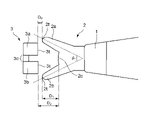
- the contact portion 2 has two legs (fingers or claws) of a first leg (2a) and a second leg (2b) as branched legs (see FIGS. 1(C) and 2). ). As shown, the bifurcated legs of the contact portion 2 may extend toward the open end so as to be gradually spaced apart from each other.
- the terminal 10 has a fitting portion for accommodating another terminal 15 (see FIGS. 6 and 7), and the fitting portion has a plate-like shape inside.
- An elastic member for example, a leaf or leaf spring
- a contact portion 2 is provided at one end of the elastic member 1, and the other end of the elastic member 1 is fixed at or around a rear end portion 4 of the fitting portion. Therefore, the end portion of the elastic member 1 having the contact portion 2 is displaceable (especially vertically displaceable) as a free end inside the fitting portion (see FIG. 1(D)).
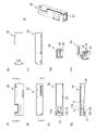
- FIG. 1A shows a top view of the fitting portion of the terminal 10 according to the first embodiment.
- FIG. 1B is a side view of one of the fitting portions of the terminal 10.
- FIG. 1(C) is a cross-sectional view of the fitting portion of the terminal 10 shown in FIG. 1(B) taken along line YY'.
- FIG. 1(D) is a cross-sectional view of the fitting portion of the terminal 10 shown in FIG. 1(A) taken along the line XX'.
- FIG. 1E is a bottom view of the fitting portion of the terminal 10.
- FIG. 1F is the other side view of the fitting portion of the terminal 10.
- FIG. 1G is a front view of the fitting portion of the terminal 10 viewed from the opening side.
- FIG. 1G is a front view of the fitting portion of the terminal 10 viewed from the opening side.
- FIG. 1H is a perspective view of the fitting portion of the terminal 10 viewed from the opening side.
- FIG. 1(I) is a perspective view of the fitting portion of the terminal 10 viewed from the rear end side.
- a rear end portion of the terminal 10 shown in FIG. 1(I) may optionally be provided with a portion or site for attaching an electric wire.
- 4 to 7 also show the terminal 10 and another terminal 15 according to the first embodiment.
- the first leg (2a) and the second leg (2b) of the contact portion 2 may be positioned symmetrically in plan view, as shown in FIG. 2, for example.
- the first leg (2a) and the second leg (2b) may be arranged line-symmetrically with respect to the longitudinal axis of the elastic member 1, for example.
- the first leg (2a) and the second leg (2b) may be arranged at an angle to each other to form a virtual corner or corner.
- a virtual corner formed by the intersection of straight lines (for example, two dashed lines shown in FIG. 2) passing through the geometric centers of the first leg (2a) and the second leg (2b), or
- the angle ⁇ 1 of the corner is in the range of greater than 0° and 120° or less, preferably in the range of 15° or more and 60° or less.
- the first leg (2a) and the second leg (2b) may have a scissor-like shape. That is, the first leg (2a) and the second leg (2b) are arranged such that the distance between them gradually changes (for example, gradually increases toward the front side of the terminal).
- the first leg (2a) and the second leg (2b) can be called fingers or claws.
- the first leg (2a) and the second leg (2b) may be arranged parallel to each other. That is, the first leg (2a) and the second leg (2b) may be provided such that the distance between them is constant or substantially constant.
- the first leg portion (2a) and the second leg portion (2b) may have such a shape as to contact the tip portion 16 of the other terminal 15 first among the contact portions 2 (FIG. 5(C)). ) and FIG. 5(D)).
- the cross-sectional shape of the first leg (2a) and the second leg (2b) for example, the cross-sectional shape in the direction perpendicular to the dashed line shown in FIG. 2 may be a substantially U-shaped or substantially V-shaped convex shape. .
- Each length of the first leg (2a) and the second leg (2b), specifically, the distance D1 in the longitudinal direction of the terminal is, for example, 0.1 mm or more and 2 mm or less.
- FIGS. 4 and 5 show the case where the other terminal 15 is undesirably inserted obliquely.
- the tip portion 16 of the other terminal 15 comes into first contact with the first leg portion (2a) and the second leg portion (2b) of the contact portion 2 (FIG. 5(C)). ) and FIG. 5(D)). Therefore, the impact force applied to the contact portion 2, particularly the contact point (2p) can be reduced, and preferably, the plated layer provided on the contact portion 2, particularly the plated layer provided at the contact point (2p) can be scraped off. can be suppressed or reduced (see FIG. 7(D)).
- the protection portion 3 is provided so as to face the contact portion 2.
- the tip (or the tip) (3t) may be positioned between the .
- An arrangement relationship in which the leg portion and the protection portion partially overlap each other in the lateral direction of the terminal an arrangement relationship in which the protection portion is partially provided inside the branching leg portion in a plan view). It can be said that it is good to have.
- the terminals of the present disclosure can perform an anti-over function.
- the protective portion 3 may be a member that can extend from the opening of the fitting portion of the terminal 10, particularly from the bottom or bottom surface, and has a substantially U-shape or shape at or around the opening of the fitting portion. Preferably, it is folded back into a substantially V shape and can be arranged facing the contact portion 2 (see FIGS. 1(C), 1(D) and 1(H)).
- the protection portion 3 may have a curved surface on the opening side (see FIG. 1(H)).
- the protection part has a curved form in which the part forming the open end of the terminal extends longer than a part (particularly, a form folded back to the rear side, or a curved form folded back from the front side to the rear side). morphology).
- the tip portion (3t) of the protection portion 3 may be bent downward, that is, toward the bottom surface of the fitting portion and/or tilted.
- the protective portion 3 Since the protective portion 3 has a folded form, the contact with the distal end portion 16 of the other terminal 15 can be alleviated (FIGS. 4(D), 5(D), 6(D) and 7 ( D)). Also, in a preferred embodiment, the protective portion having a folded form can have higher strength (can have structural strength that can more preferably withstand contact with another terminal).
- the protect part 3 may be provided with a hollow part or a recess 3c, specifically a slit, for example, in the folded back part (for example, in the part corresponding to the protect area extending from the point with the largest curvature to the rear side, such hollow portions, recesses or slits may be provided).
- the protection part 3 may have two or more branched legs, for example, a first leg (3a) and a second leg (3b) (FIGS. 1(C) and 1(G)). and FIG. 1(H)). That is, the protection portion may have portions (local portions) separated from each other in a plan view, and the portions used for the separation may have a recessed shape.
- the recess (3c) hollow portion, slit, or the like is an arbitrary configuration, and may or may not exist in the protection portion 3 .
- the first leg ( 3 a ) of the protection portion 3 can be arranged facing or adjacent to the first leg ( 2 a ) of the contact portion 2 .
- the second leg ( 3 b ) of the protection portion 3 can be arranged facing or adjacent to the second leg ( 2 b ) of the contact portion 2 . That is, the first leg (3a) is provided more proximal to the first leg (2a), while the second leg (3b) is more proximal to the second leg (2b). may be provided as
- At least part of the protection portion 3 may be positioned between the first leg (2a) and the second leg (2b) of the contact portion 2 in plan view.
- at least a part of the first leg (3a) and the second leg (3b) of the protection part 3 is between the first leg (2a) and the second leg (2b) of the contact part 2. located in the spatial domain.
- each tip (especially each tip end) 3t of the first leg (3a) and the second leg (3b) of the protection part 3 is the contact part 2, preferably the contact part 2. It can be located close to or adjacent to an intermediate portion (or bifurcation or crotch) 2c provided between one leg (2a) and a second leg (2b).
- the intermediate portion 2c of the contact portion 2 (that is, the contact portion contour portion located between the legs separated from each other in plan view) may or may not be present, but the intermediate portion (2c) is present.
- the tip (3t) of the protection portion 3 can be easily positioned closer to or adjacent to the contact portion 2. As shown in FIG.
- the first leg (3a) and the second leg (3b) of the protection part 3 and the first leg (2a) and the second leg (2b) of the contact part 2 have mutually complementary shapes. (in particular, at least part of their contours may be complementary to each other in plan view). For example, adjacent sides may be positioned in a substantially parallel relationship. Moreover, the tip portion 3t of the protection portion 3 and the intermediate portion 2c of the contact portion 2 may have shapes complementary to each other so that they are positioned close to or adjacent to each other.
- the tip portion (3t) of the protection portion 3 When the tip portion (3t) of the protection portion 3 is positioned between the first leg portion (2a) and the second leg portion (2b) of the contact portion 2, the other terminal 15 can be smoothly inserted into the fitting portion. easier to guide to
- FIGS. 4 and 5 show the case where another terminal 15 is erroneously inserted obliquely.
- the tip portion 16 of the other terminal 15 can slide on the surfaces (especially the upper surface) of the first leg portion (3a) and the second leg portion (3b) of the protection portion 3.
- the tip portion 16 of the other terminal 15 contacts at least a part of the first leg (2a) and the second leg (2b) of the contact portion 2, for example, at least one of their faces (especially the upper face).
- FIGS. 5(C) and 5(D) See FIGS. 5(C) and 5(D)
- the tip 16 of the other terminal 15 can slide on the upper surface of the first leg (2a) and the second leg (2b) of the contact portion 2 (Fig. 5(C), 5(D) and 7(D)).
- the lower surface of the other terminal 15 comes into physical and/or electrical contact with the contact portion 2 to form a contact point 2p.
- the tip portion 16 of the other terminal 15 contacts. While avoiding direct and/or initial contact with the point (2p), it becomes easier to smoothly introduce the other terminal 15 into the fitting portion. In particular, even when the other terminal 15 is inserted from an oblique direction, it suppresses or reduces scraping of the plated layer of the other terminal 15 and the terminal 10 of the present disclosure, especially the contact portion 2, especially the contact point (2p). As a result, the resistance value of each terminal can be further stabilized.
- the other terminal 15 is connected to the upper surface of the first leg (3a) and the second leg (3b) of the protection section 3, then the first leg (2a) and the second leg (2a) of the contact section 2 ( 2b) can be continuously slid and slid (see FIGS. 5(C) and 5(D)). Therefore, it is possible to suppress or prevent the other terminal 15 from slipping under the contact portion 2 (see FIG. 5(D)). As a result, damage to the plated layers of other terminals 15 can be easily suppressed or prevented.
- the ratio (D 3 / D 2 ) is not particularly limited.
- the ratio of D 3 /D 2 is, for example, 1/99 or more and 99/1 or less, and may be 20/80 or more and 80/20 or less. When the ratio of D 3 /D 2 is within the above range, it becomes easier to suppress scraping or reduction of the plated layer.
- a hollow portion or a concave portion (3c) may be formed in the protecting portion 3 (for example, a recessed portion of the protecting portion may be provided between legs separated from each other). It can also be said that the leg portions of the protecting portion may be connected to each other by the protecting portion (solid protecting portion) located in the recessed portion or contributing to the formation of the recessed portion.
- the presence of such a recess (3c) causes the protection portion 3 and the Areas can be provided that are not in direct contact with other terminals 15 . In other words, a non-contact portion with the protection portion 3 can be formed with respect to the other terminal 15 .
- the protection portion 3 may have a hollow portion or recess (3c) provided so as not to contact (in particular, direct contact) with other terminals 15.
- the hollow portion or recess (3c) synergistically suppresses or reduces scraping of the plated layer together with the first leg (2a) and second leg (2b) of the branched contact portion 2.
- FIG. It should be noted that "not to contact with other terminals” here means that when the terminals of the present disclosure and other terminals are combined with each other or when they are combined with each other, a portion that does not directly contact with other terminals. It refers to the mode possessed by the protection section.
- the ratio of the dimension D5 in the width direction ( perpendicular to the longitudinal axis direction) of the recess ( 3c) to the dimension D4 in the width direction (perpendicular to the longitudinal axis direction) of the protection part 3 (D5/ D4 ) is not particularly limited.
- the ratio of D 5 /D 4 is, for example, 1/99 or more and less than 50/50, and may be 10/90 or more and 30/70 or less. When the ratio of D 5 /D 4 is within the above range, it becomes easier to suppress scraping or reduction of the plated layer.
- the terminal 10 between the legs (2a, 2b) of the contact portion 2, for example, between the two tip portions (2t) of the contact portion 2, part of the protection portion 3, for example, the protection portion 3
- the two tips (2t) of the contact portion 2 and the tip (3t) of the protection portion 3 overlap in the longitudinal direction, and a distance D3 exists.
- FIG. 2 for example, as shown in FIG. It can come into contact with both ends (3t) of the protection part 3 (see FIGS. 5(C) and 5(D)). Therefore, even if the other terminal 15 is inserted from an oblique direction (see FIGS. 4B and 5B), the contact between the other terminal 15 and the contact portion 2 is prevented by dispersing the pressure. It becomes easier to avoid a direct collision at point (2p). That is, as a result, scraping of the plated layer at the contact point (2p) of the contact portion 2 can be more easily suppressed or reduced.
- the tip (3t) of the protection portion 3 may be separated from each other. That is, in a plan view, the legs of the contact portion and the protection portion may have a non-overlapping arrangement relationship in the lateral direction of the terminal. Even in such a case, scraping of the plated layers of the two terminals (10, 15) can be significantly suppressed or reduced.
- the separation direction may be the traveling direction of other terminals as in the illustrated embodiment, or may be the vertical direction (thickness direction or height direction of the terminal 10).
- the ratio of D 2 /D 1 shown in FIG. ) to the tip (3t) of the protection portion 3 should be 1 or more.
- a distance (distance in the longitudinal direction) D6 from the tip (2t) of the contact portion 2 to the tip (3t) of the protection portion 3 is, for example, 0 mm or more and 1 mm or less.
- the tip (2t) of the first leg (2a) of the contact portion 2, particularly the upper surface of the tip (2t) and/or the second leg ( 2b), the tip (2t), especially the upper surface of the tip (2t), may be positioned lower than the tip (3t), especially the upper surface of the tip (3t) of the protection part 3 (FIG. 4(D) reference).
- the tip (3t) of the protection portion 3, especially the upper surface of the tip (3t), the tip (2t) of the first leg (2a) of the contact portion 2, especially the upper surface of the tip (2t) and /or it may be positioned higher than the tip (2t) of the second leg (2b), in particular the upper surface of the tip (2t). That is, in the state of the terminal before being combined with other terminals, the extreme edge of the first leg (2a) and/or the second leg (2b) of the contact portion 2 branching and extending forward may be positioned lower than the farthest edge of the protection portion 3 extending so as to be folded rearward.
- the tip level of the first leg ( 2 a ) and/or the second leg ( 2 b ) of the contact portion 2 may be lower than the tip level of the protection portion 3 .
- the contact area of the first leg ( 2 a ) and/or the second leg ( 2 b ) other than the extreme edge may include a portion positioned higher than the protection portion 3 .
- the other terminal 15 slides and slides on the upper surfaces of the first leg (3a) and the second leg (3b) of the protection portion 3, and then slides on the upper surface of the first leg (3a) and second leg (3b) of the contact portion 2.
- the upper surface of the leg portion (2a) and the second leg portion (2b) can be continuously and smoothly slid/slid easily (see FIG. 5(C)). Therefore, it becomes easier to suppress or prevent the other terminals 15, particularly the tip portion 16, from slipping under the contact portion 2, and by extension, damage to the plated layer of the other terminals 15 (see FIG. 5D).
- the angle is, for example, 1° or more and less than 90°, preferably 1° or more and 60° or less, more preferably 1° or more. Even when the other terminal 15 is inserted obliquely at an angle of 45° or less, the other terminal 15 can be more successfully inserted into the fitting portion of the terminal 10 (see FIGS. 4 and 5). At that time, the risk of damaging the two terminals (10, 15), particularly the plating layer of the contact portion 2 of the terminal 10 of the present disclosure, can be relatively greatly reduced.
- the terminal 10 makes it easier to significantly reduce the abrasion of the plated layers of the two terminals (10, 15), and the physical and physical contact between the other terminal 15 and the contact portion 2.
- the contact point 2p can be formed more simply by electrical contact (see FIG. 7(D)). As a result, it becomes easier to stabilize the resistance values of the two terminals (10, 15).
- the first leg portion (2a) and the second leg portion (2b) of the contact portion 2 may be coupled to each other to form a ring.
- the ends of the branched first leg (2a) and the second leg (2b) may be connected to each other.
- the contact portion may have an annular shape including the first leg (2a) and the second leg (2b). Note that the contact portion 2 may form a ring continuously with, for example, the first leg portion (2a), the second leg portion (2b), and the intermediate portion (2c).
- the shape of the ring is not particularly limited, and may be substantially circular (including oval, oval, teardrop, etc.), substantially rectangular (including quadrilateral, trapezoid, etc.), substantially triangular, and polygons with pentagons or more. It's okay. More specifically, the contact portion 2 may have a shape similar to that of a bottle opener, a goldfish scooping tool, or a magnifying glass frame. Thus, when the first leg (2a) and the second leg (2b) of the contact portion (2) are connected to each other at their tips, a higher structural strength can be provided to the contact portion.
- a terminal according to a second embodiment of the present disclosure is shown in FIGS. 8-14.
- the terminal (20) according to the second embodiment mainly has the following features.
- a terminal 20 according to the second embodiment is a terminal that can accommodate another terminal 25 .
- terminal 20 has a mating portion for receiving another terminal 25 (see FIGS. 8, 13 and 14).
- the fitting portion has a contact portion 22 and a protection portion 23 (see FIGS. 8 and 9).
- the contact portion 22 is a portion that can include a contact point (22p) with another terminal 25 that can be accommodated in the fitting portion (see FIG. 14(D)).
- the protection portion 23 is provided at the open end of the terminal 20 .
- the protection portion 23 is provided at the opening of the fitting portion (see FIGS. 8(G) and 8(H)).
- the contact portion 22 and the protection portion 23 are positioned so as to face each other (see FIG. 8C and the top view of FIG. 9).
- the contact portion 22 and the protection portion 23 may be provided adjacent to each other (particularly, they may be aligned or adjacent to each other along the axial direction of the terminal).
- the protect portion 23 has two legs (fingers or claws), a first leg (23a) and a second leg (23b), as branched legs (fingers or claws) (FIG. 8). (C) and see FIG. 9).
- the terminal 20 according to the second embodiment includes an elastic member 21.
- the elastic member 21 has a contact portion 22 at one end like the elastic member 1 included in the terminal 10 according to the first embodiment, and the other end is the rear end portion of the fitting portion or its periphery. Fixed.
- the elastic member 21 included in the terminal 20 according to the second embodiment is a member that can correspond to the elastic member 1 included in the terminal 10 according to the first embodiment.
- the contact portion 22 included in the terminal 20 according to the second embodiment is a portion or site that can correspond to the contact portion 2 included in the terminal 10 according to the first embodiment.
- the protection portion 23 included in the terminal 20 according to the second embodiment is a portion or site that can correspond to the protection portion 3 included in the terminal 10 according to the first embodiment.
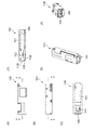
- FIG. 8A shows a top view of the fitting portion of the terminal 20 according to the second embodiment.
- FIG. 8B is a side view of one of the fitting portions of the terminal 20.
- FIG. FIG. 8(C) is a cross-sectional view of the fitting portion of the terminal 20 shown in FIG. 8(B) taken along line YY'.
- FIG. 8(D) is a cross-sectional view of the fitting portion of the terminal 20 shown in FIG. 8(A) taken along line XX'.
- FIG. 8E is a bottom view of the fitting portion of the terminal 20.
- FIG. FIG. 8F is the other side view of the fitting portion of the terminal 20.
- FIG. FIG. 8G is a front view of the fitting portion of the terminal 20 viewed from the opening side.
- FIG. 8G is a front view of the fitting portion of the terminal 20 viewed from the opening side.
- FIG. 8H is a perspective view of the fitting portion of the terminal 20 viewed from the opening side.
- FIG. 8I is a perspective view of the fitting portion of the terminal 20 viewed from the rear end side.
- a rear end portion of the terminal 20 shown in FIG. 8(I) may optionally be provided with a portion or site for attaching an electric wire.
- 11 to 14 also show the terminal 20 and another terminal 25 according to the second embodiment.
- first leg (23a) and a second leg (23b) may have a form that branches and extends from the front to the rear. It can also be said that the first leg (23a) and the second leg (23b) may protrude rearward in plan view.
- the first leg (23a) and the second leg (23b) of the protection section 23 may be positioned symmetrically in a plan view, as shown in FIG. 9, for example.
- the first leg ( 23 a ) and the second leg ( 23 b ) of protect portion 23 may be arranged line-symmetrically with respect to the longitudinal axis of the fitting portion of terminal 20 .
- the contact portion 22 is between the first leg (23a) and the second leg (23b) of the protection portion 23 in plan view. (22t) may be located. Due to such a positional relationship, for example, even when the contact portion 22 is displaced in the horizontal direction (or the width direction) as well as in the vertical direction, the tip portion 22t of the contact portion 22 is positioned at the first leg portion (23a) of the protection portion 23. And/or the contact portion 22 can be returned to its original position (or the central or central position) by contacting or interfering with the second leg portion (23b). In other words, the terminal of the present disclosure can serve as a guide.
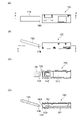
- FIGS. 11 and 12 show the case where another terminal 25 is undesirably inserted obliquely.
- the tip portion 26 of the other terminal 25 contacts the upper surface of the protect portion 23 and then at least one of the first leg portion (23a) and the second leg portion (23b) of the protect portion 23. becomes (see FIG. 12(D)). Therefore, the first leg portion (23a) and the second leg portion (23b) of the protection portion 23 receive the impact force applied to the contact portion 22, particularly the contact point (22p), thereby reducing the impact force or pressure.
- another terminal 25 slides and slides on the upper surfaces of the first leg (23a) and the second leg (23b) of the protection section 23, so that the plated layer provided on the contact section 22, particularly the contact point 22p, is removed. It is possible to suppress or reduce scraping of the plated layer (see FIG. 14(D)). This is because the tip 26 of the other terminal 25 does not directly and/or first contact the plated layer of the contact point 22p. By providing two or more leg portions (23a, 23b) in the protection portion in this way, scraping of the plated layer is suppressed or reduced, thereby facilitating stabilization of the resistance value of the terminal.
- the tip portion (22t) between the first leg (23a) and the second leg (23b) of the protection portion 23
- the other terminal 25 slides continuously on the surface (especially the upper surface) of the first leg (23a) and the second leg (23b) of the protection portion 23, and then the surface (especially the upper surface) of the contact portion 22. be able to. Therefore, it is possible to suppress or prevent the other terminal 25 , particularly the tip portion 26 , from slipping under the contact portion 22 . As a result, it is possible to suppress or prevent damage to the plated layers of other terminals 25 (see FIG. 12(D)).
- another terminal 25 continuously slides and slides on the upper surface of the first leg (23a) and the second leg (23b) of the protection portion 23 and then the upper surface of the contact portion 22 (FIG. 12 ( C) and FIG. 12(D)), it becomes easier to smoothly introduce the other terminal 25 into the fitting portion (see FIG. 14(D)). Therefore, damage to the other terminal 25 and the contact portion 22 of the terminal 20 according to the second embodiment, particularly the plated layer of the contact point 22p, is further suppressed or prevented.
- the protection portion 23 is a member that can extend from the opening of the fitting portion of the terminal 20 , particularly from the bottom or bottom surface, and is folded back into a substantially U-shape or a substantially V-shape at the opening of the fitting portion to form the contact portion 22 . Preferably, they can be arranged oppositely (see top views of FIGS. 8(D), 8(H) and 9).
- the protection portion 23 preferably has a curved surface on the opening side (see FIGS. 8(D) and 8(H)).
- the protect portion may have a curved form (particularly, a form folded back toward the rear) in which the portion forming the open end of the terminal extends longer than a part of the protect portion.
- the tip of the protection portion 23 for example, the tip 23t of the first leg (23a) and the second leg (23b) is bent downward, that is, toward the bottom surface of the fitting portion. , and/or may be tilted (see FIG. 8(D)).
- the length of each of the first leg (23a) and the second leg (23b) of the protection portion 23, specifically, the distance D7 in the longitudinal axis direction of the terminal is, for example, 0.5. It is 1 mm or more and 1 mm or less.
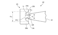
- An intermediate portion 23c may be provided between the first leg portion (23a) and the second leg portion (23b) of the protection portion 23.
- the first leg (23a) or the second leg of the protect portion 23 relative to the maximum distance ( longitudinal distance) D8 between the intermediate portion (23c) of the protect portion 23 and the tip portion 22t of the contact portion 22
- the ratio of D 9 /D 8 is, for example, 1/99 or more and 99/1 or less, and may be 30/70 or more and 70/30 or less.
- the ratio of the dimension D11 in the width direction (perpendicular to the longitudinal direction) of the contact portion 22 to the distance (perpendicular to the longitudinal direction) D10 between the two tips ( 23t ) of the protection portion 23 is not particularly limited.
- the ratio of D 11 /D 10 is, for example, 1/99 or more and less than 50/50, and may be 30/70 or more and 40/60 or less. When the ratio of D 11 /D 10 is within the above range, it becomes easier to suppress scraping of the plated layer.
- the first leg (23a) and/or the second leg (23b) of the protection part 23 may open outward from each other. In other words, it may extend or protrude obliquely outward.
- the two tips ( 23t ) of the protection portion 23 and the tips (22t) of the contact portion 22 overlap in the longitudinal direction and a distance D9 exists.
- FIG. 9 for example, as shown in FIG. It can come into contact with both tip portions (22t) of the contact portion 22 (see FIG. 12(D)). Therefore, even if the other terminal 25 is inserted obliquely (see FIGS. 11B and 12B), the pressure is dispersed to prevent contact between the other terminal 25 and the contact portion 22 . It becomes easier to avoid a direct collision at the point (22p). That is, as a result, scraping of the plated layer at the contact point (22p) of the contact portion 22 can be more easily suppressed or reduced.
- the tip portion (22t) of the contact portion 22 may be separated from each other. That is, in a plan view, the leg portions of the protection portion and the contact portions may have a non-overlapping arrangement relationship in which they do not overlap each other in the transverse direction of the terminal. Even in such a case, scraping of the plated layers of the two terminals (20, 25) can be significantly suppressed or reduced.
- the separation direction may be the traveling direction of the other terminals as in the illustrated embodiment, or may be the vertical direction (thickness direction or height direction of the terminal 20).
- the maximum length (lengthwise distance) D ( 8 ratio) from the tip (22t) to the protection portion 23 (specifically, the intermediate portion (23c)) should be 1 or more.
- a distance (lengthwise distance) D12 between the tip ( 23t ) of the protection portion 23 and the tip (22t) of the contact portion 22 is, for example, 0 mm or more and 1 mm or less.
- the tip (23t) of the first leg (23a) of the protection portion 23, particularly the upper surface of the tip (23t) and/or the second leg ( 23b), especially the upper surface of the tip (23t), may be positioned higher than the tip (22t) of the contact part 22, especially the upper surface of the tip (22t) (Fig. 11 (D )reference).
- the tip (22t) of the contact portion 22, especially the upper surface of the tip (22t), the tip (23t) of the first leg (23a) of the protection portion 23, especially the upper surface of the tip (23t) and /or may be positioned lower than the tip (23t) of the second leg (23b), in particular the upper surface of the tip (23t).
- the first leg (23a) and/or the second leg (23b) at the extreme edge of the protection portion 23 extending to fold back to the rear side.
- the extreme edge may be positioned higher than the extreme edge of the forwardly extending contact portion 22 .
- the tip level of the first leg ( 23 a ) and/or the second leg ( 23 b ) of the protecting portion may be higher than the tip level of the contact portion 22 .
- the region other than the extreme edge of the contact portion may include a portion positioned higher than the protect portion.
- the other terminal 25 is smoothly connected to the upper surface of the first leg (23a) and the second leg (23b) of the protection portion 23, and then the upper surface of the contact portion 22. It is possible to slide and slide on Therefore, it becomes easier to suppress or prevent the tip portion 26 of the other terminal 25 from slipping under the tip portion 22t of the contact portion 22, and it becomes easier to suppress or prevent damage to the plated layer of the other terminal 25. .
- the angle is, for example, 1° or more and less than 90°, preferably 1° or more and 60° or less, more preferably 1° or more. Even if the other terminal 25 is inserted obliquely at an angle of 45° or less, the other terminal 25 can be more successfully inserted into the fitting portion (Figs. 11, 12 and 14 (D )reference).
- the possibility of damaging the two terminals (20, 25) for example, the contact portion 22 of the terminal 20 of the present disclosure, particularly the plating layer of the contact point 22p, can be relatively significantly reduced (FIGS. 11(D) and 12). (D) and FIG. 14(D)). As a result, scraping of the plated layers of the two terminals (20, 25) can be greatly reduced.
- scraping of the plated layers of the two terminals (20, 25) can be greatly reduced, and physical and electrical contact between the other terminal 25 and the contact portion 22 can be reduced.
- a contact point 22p can be formed by such contact (see FIG. 14(D)).
- the resistance values of the two terminals (20, 25) are made easier to stabilize.
- terminals of the present disclosure have been described in detail in the first and second embodiments, but the terminals of the present disclosure should not be construed as being limited to the first and second embodiments.
- the configurations or elements described in the first and second embodiments may be used in any suitable combination within the scope of the idea or spirit of the present disclosure.
- the recess 3c provided in the protect portion 3 of the terminal 10 according to the first embodiment may be formed in the protect portion 23 of the terminal 20 according to the second embodiment. By doing so, scraping of the plated layer can be more easily suppressed.
- the contact portion may be composed of an elastic member.
- the contact portion may be composed of an elastic member so as to press or be able to press another terminal (FIGS. 1(D), 7(D), 8(D) and 14(D). reference).
- “to press the other terminal” means that when the terminal of the present disclosure and the other terminal are combined with each other or when the other terminal is combined, an external force is exerted on the other terminal due to the contact portion. (for example, when another terminal is inserted into the opening of the terminal of the present disclosure, an external force that resists the insertion is exerted on the other terminal).
- the elastic member may have both a free end and a fixed end, thereby pressing against the other terminal. More specifically, the elastic member has both a free end and a fixed end, the free end has a contact portion, the fixed end is fixed to the fitting portion, and the other terminal is accommodated in the fitting portion. It may be configured such that the contact portion provided at the free end is displaced while the other terminal is pressed (see FIGS. 7(D) and 14(D)). With such a configuration of the terminal of the present disclosure, when the other terminal is accommodated in the fitting portion, it is easier to elastically hold the other terminal in the fitting portion more appropriately. On the other hand, the terminal of the present disclosure can suppress or reduce scraping of the plated layer. That is, according to the terminal of the present disclosure, preferably, it is possible to more successfully achieve both of the two conflicting performances of pressing other terminals and suppressing scraping of the plated layer.
- the terminal of the present disclosure can be used in a wide range of fields where electrical connections are required.
- the field of application is not particularly limited, but the terminals of the present disclosure can be used, for example, for electrical connections in the electromechanical field.
- the terminal of the present disclosure can be utilized in fields where more stabilized resistance and/or pressing force are required, for example, in the field of vehicles such as automobiles, hybrid automobiles, and electric automobiles.
- the terminals of the present disclosure can be used as terminals for connecting to a vehicle computer such as an ECU. It can also be used in various vehicles and devices including computers.
Landscapes
- Connections Effected By Soldering, Adhesion, Or Permanent Deformation (AREA)
Priority Applications (1)
| Application Number | Priority Date | Filing Date | Title |
|---|---|---|---|
| JP2022579558A JPWO2022168841A1 (https=) | 2021-02-03 | 2022-02-01 |
Applications Claiming Priority (2)
| Application Number | Priority Date | Filing Date | Title |
|---|---|---|---|
| JP2021015824 | 2021-02-03 | ||
| JP2021-015824 | 2021-02-03 |
Publications (1)
| Publication Number | Publication Date |
|---|---|
| WO2022168841A1 true WO2022168841A1 (ja) | 2022-08-11 |
Family
ID=82741511
Family Applications (1)
| Application Number | Title | Priority Date | Filing Date |
|---|---|---|---|
| PCT/JP2022/003889 Ceased WO2022168841A1 (ja) | 2021-02-03 | 2022-02-01 | 端子 |
Country Status (2)
| Country | Link |
|---|---|
| JP (1) | JPWO2022168841A1 (https=) |
| WO (1) | WO2022168841A1 (https=) |
Citations (4)
| Publication number | Priority date | Publication date | Assignee | Title |
|---|---|---|---|---|
| JPH02110184U (https=) * | 1989-02-20 | 1990-09-04 | ||
| JP2000150041A (ja) * | 1998-09-11 | 2000-05-30 | Jst Mfg Co Ltd | コネクタの端子及びハウジング |
| JP2011530154A (ja) * | 2008-08-04 | 2011-12-15 | タイコ・エレクトロニクス・コーポレイション | ソケットコンタクト |
| WO2014096886A1 (en) * | 2012-12-21 | 2014-06-26 | Delphi International Operations Luxembourg S.À.R.L. | Assembly of male terminal and female terminal having a contact point and a retention arm |
-
2022
- 2022-02-01 JP JP2022579558A patent/JPWO2022168841A1/ja active Pending
- 2022-02-01 WO PCT/JP2022/003889 patent/WO2022168841A1/ja not_active Ceased
Patent Citations (4)
| Publication number | Priority date | Publication date | Assignee | Title |
|---|---|---|---|---|
| JPH02110184U (https=) * | 1989-02-20 | 1990-09-04 | ||
| JP2000150041A (ja) * | 1998-09-11 | 2000-05-30 | Jst Mfg Co Ltd | コネクタの端子及びハウジング |
| JP2011530154A (ja) * | 2008-08-04 | 2011-12-15 | タイコ・エレクトロニクス・コーポレイション | ソケットコンタクト |
| WO2014096886A1 (en) * | 2012-12-21 | 2014-06-26 | Delphi International Operations Luxembourg S.À.R.L. | Assembly of male terminal and female terminal having a contact point and a retention arm |
Also Published As
| Publication number | Publication date |
|---|---|
| JPWO2022168841A1 (https=) | 2022-08-11 |
Similar Documents
| Publication | Publication Date | Title |
|---|---|---|
| JP4172658B2 (ja) | 高力コンタクト | |
| US6921270B2 (en) | Electrical connector | |
| JP4650918B2 (ja) | 電気コネクタ | |
| KR940022952A (ko) | 암전기단자 | |
| US5741162A (en) | Electrical contact having improved locking lances | |
| EP2876743B1 (en) | Connector between cable and substrate | |
| US5645458A (en) | Electrical receptacle terminal | |
| JP2000150041A (ja) | コネクタの端子及びハウジング | |
| JP2008123720A (ja) | 雌型コンタクト | |
| JPH04294073A (ja) | タブ形コンタクト | |
| CN1909297B (zh) | 双梁插座触头 | |
| US8043130B2 (en) | Female electrical contact comprising spring contact plates | |
| US20200274270A1 (en) | Chained terminals and board connector with terminals in chained terminals | |
| JP4226737B2 (ja) | フラットケーブル用コネクタ及びその製造方法 | |
| WO2022168841A1 (ja) | 端子 | |
| KR101665473B1 (ko) | 단자 | |
| US6322403B1 (en) | Low insertion force mating electrical contact structure | |
| US20090269966A1 (en) | Lever-fitting connector | |
| CN112350093B (zh) | 净主体式电端子 | |
| JP3468880B2 (ja) | 接続端子 | |
| JP7322499B2 (ja) | 電気コネクタ、および電気コネクタ装置 | |
| US12368257B2 (en) | Terminal fitting and connector with deformation-suppressible elastic contact portion | |
| JPH10125378A (ja) | 雌型端子 | |
| JP2024036858A (ja) | 端子ユニット,雌端子,雄端子 | |
| US7544098B2 (en) | Connector having a stopper mechanism defining a movable range of a housing receiving a connection object |
Legal Events
| Date | Code | Title | Description |
|---|---|---|---|
| 121 | Ep: the epo has been informed by wipo that ep was designated in this application |
Ref document number: 22749713 Country of ref document: EP Kind code of ref document: A1 |
|
| ENP | Entry into the national phase |
Ref document number: 2022579558 Country of ref document: JP Kind code of ref document: A |
|
| NENP | Non-entry into the national phase |
Ref country code: DE |
|
| 122 | Ep: pct application non-entry in european phase |
Ref document number: 22749713 Country of ref document: EP Kind code of ref document: A1 |