WO2022168779A1 - Bracket fixing member, buffer, and manufacturing method for buffer - Google Patents
Bracket fixing member, buffer, and manufacturing method for buffer Download PDFInfo
- Publication number
- WO2022168779A1 WO2022168779A1 PCT/JP2022/003557 JP2022003557W WO2022168779A1 WO 2022168779 A1 WO2022168779 A1 WO 2022168779A1 JP 2022003557 W JP2022003557 W JP 2022003557W WO 2022168779 A1 WO2022168779 A1 WO 2022168779A1
- Authority
- WO
- WIPO (PCT)
- Prior art keywords
- bracket
- arcuate
- cylinder
- arc
- base member
- Prior art date
Links
- 239000000872 buffer Substances 0.000 title claims abstract description 11
- 238000004519 manufacturing process Methods 0.000 title claims description 28
- 230000002093 peripheral effect Effects 0.000 claims abstract description 114
- 238000003466 welding Methods 0.000 claims abstract description 83
- 239000006096 absorbing agent Substances 0.000 claims description 59
- 230000035939 shock Effects 0.000 claims description 59
- 238000000034 method Methods 0.000 claims description 31
- 239000000463 material Substances 0.000 claims description 9
- 238000000465 moulding Methods 0.000 claims description 6
- 238000002360 preparation method Methods 0.000 description 15
- 230000006866 deterioration Effects 0.000 description 14
- 239000011810 insulating material Substances 0.000 description 10
- 238000013016 damping Methods 0.000 description 7
- 230000006835 compression Effects 0.000 description 4
- 238000007906 compression Methods 0.000 description 4
- 239000012530 fluid Substances 0.000 description 3
- 238000003825 pressing Methods 0.000 description 3
- 239000007788 liquid Substances 0.000 description 2
- 230000013011 mating Effects 0.000 description 2
- 239000002184 metal Substances 0.000 description 2
- 239000000725 suspension Substances 0.000 description 2
- 238000013459 approach Methods 0.000 description 1
- 239000003795 chemical substances by application Substances 0.000 description 1
- 230000007423 decrease Effects 0.000 description 1
- 230000010354 integration Effects 0.000 description 1
- 238000012986 modification Methods 0.000 description 1
- 230000004048 modification Effects 0.000 description 1
- 230000000149 penetrating effect Effects 0.000 description 1
- 238000004080 punching Methods 0.000 description 1
Images


Classifications
-
- B—PERFORMING OPERATIONS; TRANSPORTING
- B60—VEHICLES IN GENERAL
- B60G—VEHICLE SUSPENSION ARRANGEMENTS
- B60G15/00—Resilient suspensions characterised by arrangement, location or type of combined spring and vibration damper, e.g. telescopic type
- B60G15/02—Resilient suspensions characterised by arrangement, location or type of combined spring and vibration damper, e.g. telescopic type having mechanical spring
- B60G15/06—Resilient suspensions characterised by arrangement, location or type of combined spring and vibration damper, e.g. telescopic type having mechanical spring and fluid damper
-
- B—PERFORMING OPERATIONS; TRANSPORTING
- B60—VEHICLES IN GENERAL
- B60G—VEHICLE SUSPENSION ARRANGEMENTS
- B60G7/00—Pivoted suspension arms; Accessories thereof
-
- F—MECHANICAL ENGINEERING; LIGHTING; HEATING; WEAPONS; BLASTING
- F16—ENGINEERING ELEMENTS AND UNITS; GENERAL MEASURES FOR PRODUCING AND MAINTAINING EFFECTIVE FUNCTIONING OF MACHINES OR INSTALLATIONS; THERMAL INSULATION IN GENERAL
- F16F—SPRINGS; SHOCK-ABSORBERS; MEANS FOR DAMPING VIBRATION
- F16F9/00—Springs, vibration-dampers, shock-absorbers, or similarly-constructed movement-dampers using a fluid or the equivalent as damping medium
- F16F9/32—Details
- F16F9/54—Arrangements for attachment
Definitions
- the present invention relates to a bracket fixing member, a shock absorber, and a manufacturing method of the shock absorber.
- shock absorbers with brackets attached there are shock absorbers with brackets attached (see Patent Documents 1 and 2, for example).
- the bracket may be attached to the base member by resistance welding. It is desired to suppress deterioration in welding quality in such an attachment structure.
- the present invention provides a bracket fixing member, a shock absorber, and a method of manufacturing the shock absorber that can suppress deterioration in welding quality.
- the bracket fixing member has a cylindrical or arcuate base member, and a plurality of fixing portions provided in the circumferential direction of the base member, and the bracket fixing member is provided on the outer peripheral side of the base member.
- the fixing portions are fixed to the base member so as to overlap each other by resistance welding, and at least the curvature of the outer portion in the circumferential direction is formed to spread in the outer diameter direction more than the curvature between the plurality of fixing portions.
- a bracket comprising an arcuate portion that is curved.
- the damper comprises a cylindrical cylinder.
- This shock absorber is formed by molding a plate material so as to cover at least a portion of the outer peripheral side of the cylinder, and has a first bracket and a second bracket fixed to the cylinder.
- the second bracket has a holding portion for holding another member and a plurality of fixed portions in the circumferential direction of the base member composed of the cylinder or the first bracket, and is arranged so as to overlap the outer peripheral side of the base member.
- the fixing portion is fixed to the base member by resistance welding, and the arc shape is formed such that the curvature of the outer portion in the circumferential direction is wider than the curvature between at least a plurality of the fixing portions in the outer diameter direction.
- a method of manufacturing a shock absorber having a cylindrical cylinder comprises: a first bracket and a second bracket at least partially formed in an arc shape; is a first arcuate portion formed in an arcuate shape, and a plurality of protrusions protruding to the inner peripheral side of the first arcuate portion; preparing a second bracket having a second arc-shaped portion formed to be wider in the outer diameter direction than the first arc-shaped portion; fixing the first bracket to the cylinder; Alternatively, a step of arranging the second bracket so that the protruding portion abuts against the outer periphery of the base member composed of the first bracket, and a step of applying an electric current between the base member and the protruding portion to perform resistance welding. , including.
- shock absorber and the method for manufacturing the shock absorber described above it is possible to suppress deterioration in welding quality.
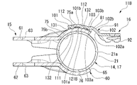
- FIG. 3 is a cross-sectional view taken along line III-III in FIG. 2, showing the essential parts of the shock absorber according to the first embodiment of the present invention; It is sectional drawing before a 2nd bracket welding process after a 2nd bracket arrangement
- FIG. 1 A first embodiment of the present invention will be described below with reference to FIGS. 1 to 4.
- FIG. 1 A first embodiment of the present invention will be described below with reference to FIGS. 1 to 4.
- FIG. 1 shows the shock absorber 11 (bracket fixing member) of the first embodiment.
- the shock absorber 11 is used in a suspension device for vehicles such as automobiles and railroad vehicles. Specifically, it is a shock absorber used in strut-type suspensions of automobiles.
- the shock absorber 11 is attached by welding to a cylindrical inner cylinder 12, a bottomed cylindrical outer cylinder 14, a first bracket 15 (base member), and the outer peripheral side of the first bracket 15 as shown in FIG. and a second bracket 16 (bracket).
- the outer cylinder 14 has a larger diameter than the inner cylinder 12 .
- the outer cylinder 14 is provided on the outer peripheral side of the inner cylinder 12 and forms a reservoir chamber 13 between itself and the inner cylinder 12 .
- the first bracket 15 is attached to the outer peripheral side of the outer cylinder 14 by welding.
- the inner cylinder 12 and the outer cylinder 14 shown in FIG. 1 constitute a cylindrical cylinder 17 .
- the outer cylinder 14 is an integrally molded product made of one metal member.
- the outer cylinder 14 has a cylindrical side wall portion 21 , a bottom portion 22 closing one end side of the side wall portion 21 in the axial direction, and an opening portion 23 on the side opposite to the bottom portion 22 of the side wall portion 21 .
- the shock absorber 11 has an annular body member 30 attached to one axial end of the inner cylinder 12 and an annular rod guide 31 attached to the other axial end of the inner cylinder 12 .
- the inner cylinder 12 is fitted to the bottom portion 22 of the outer cylinder 14 via the body member 30 .
- the inner cylinder 12 is fitted to the opening 23 side of the side wall 21 of the outer cylinder 14 via the rod guide 31 . In this state, the inner cylinder 12 is radially and axially positioned with respect to the outer cylinder 14 .
- the shock absorber 11 has an annular seal member 33 on the opposite side of the rod guide 31 from the bottom portion 22 .
- the seal member 33 is fitted to the inner peripheral portion of the side wall portion 21 on the side of the opening portion 23 .
- a locking portion 34 is formed at the end portion of the side wall portion 21 opposite to the bottom portion 22 .
- the locking portion 34 is formed by plastically deforming radially inward by curling.
- the seal member 33 is sandwiched between the locking portion 34 and the rod guide 31 .
- the shock absorber 11 has a piston 35 slidably fitted in the inner cylinder 12 .
- the piston 35 defines a first chamber 38 and a second chamber 39 within the inner cylinder 12 .
- the first chamber 38 is provided between the piston 35 and the rod guide 31 inside the inner cylinder 12 .
- the second chamber 39 is provided between the piston 35 and the body member 30 inside the inner cylinder 12 .
- a second chamber 39 in the inner cylinder 12 is defined as the reservoir chamber 13 by the body member 30 .
- the first chamber 38 and the second chamber 39 in the inner cylinder 12 are filled with an oil liquid, which is a working fluid.
- a reservoir chamber 13 between the inner cylinder 12 and the outer cylinder 14 is filled with gas and oil as working fluids.
- the buffer 11 has a piston rod 41.
- One side of the piston rod 41 is coupled to the piston 35 .
- the other side of the piston rod 41 extends outside through the opening 23 from the outer cylinder 14 .
- a piston 35 is connected to the piston rod 41 by a nut 43 .
- the piston rod 41 extends outside from the inner cylinder 12 and the outer cylinder 14 through the rod guide 31 and the seal member 33 .
- a portion of the piston rod 41 extending from the outer cylinder 14 to the outside is connected to the vehicle body side.
- the piston rod 41 is guided by the rod guide 31 and axially moves together with the piston 35 relative to the inner cylinder 12 and the outer cylinder 14 .
- the seal member 33 closes the space between the outer cylinder 14 and the piston rod 41 to restrict leakage of the oil in the inner cylinder 12 and the gas and oil in the reservoir chamber 13 to the outside.
- a passage 44 and a passage 45 are formed through the piston 35 in the axial direction. Passages 44 and 45 can communicate between first chamber 38 and second chamber 39 .
- the damper 11 has an annular disk valve 46 on the axial side of the piston 35 opposite the bottom 22 . The disk valve 46 can close the passage 44 by contacting the piston 35 .
- the shock absorber 11 also has an annular disk valve 47 on the bottom 22 side of the piston 35 in the axial direction. The disc valve 47 can block the passage 45 by coming into contact with the piston 35 .
- the disc valve 46 is a compression side damping valve. That is, the piston rod 41 moves to the compression side to increase the amount of entry into the inner cylinder 12 and the outer cylinder 14, the piston 35 moves in the direction to narrow the second chamber 39, and the pressure in the second chamber 39 increases to the first pressure.
- the disk valve 46 opens the passage 44 when the pressure in the chamber 38 exceeds the predetermined value. A damping force is generated when the disc valve 46 opens the passage 44 .
- At least one of the piston 35 and the disc valve 46 has a fixed orifice (not shown) that allows the first chamber 38 and the second chamber 39 to communicate with each other through the passage 44 even when the disc valve 46 closes the passage 44 to the maximum. formed.
- the disk valve 47 is a damping valve on the extension side. That is, the piston rod 41 moves to the extension side to increase the amount of protrusion from the inner cylinder 12 and the outer cylinder 14, the piston 35 moves in the direction to narrow the first chamber 38, and the pressure in the first chamber 38 increases to the second chamber.
- the disc valve 47 opens the passage 45 when the pressure at 39 is higher than the pressure by a predetermined value. A damping force is generated when the disc valve 47 opens the passage 45 .
- At least one of the piston 35 and the disc valve 47 has a fixed orifice (not shown) that allows the first chamber 38 and the second chamber 39 to communicate with each other through the passage 45 even when the disc valve 47 closes the passage 45 to the maximum. formed.
- a passage 52 and a passage 53 are formed through the body member 30 in the axial direction. Passages 52 and 53 are capable of communicating second chamber 39 and reservoir chamber 13 .
- An annular disc valve 55 is provided on the bottom portion 22 side of the body member 30 in the axial direction.
- An annular disk valve 56 is provided on the axial side of the body member 30 opposite the bottom portion 22 . The disk valve 55 can block the passage 52 by coming into contact with the body member 30 .
- the disc valve 56 can block the passage 53 by coming into contact with the body member 30 .
- the disc valve 55 is a compression side damping valve. That is, when the piston rod 41 moves toward the compression side and the piston 35 moves in the direction of narrowing the second chamber 39 and the pressure in the second chamber 39 becomes higher than the pressure in the reservoir chamber 13 by a predetermined value or more, the disc valve 55 opens passageway 52 . A damping force is generated when the disc valve 55 opens the passage 52 .
- Disk valve 56 is a suction valve. That is, when the piston rod 41 moves to the extension side, the piston 35 moves to the first chamber 38 side, and the pressure in the second chamber 39 becomes lower than the pressure in the reservoir chamber 13, the passage 53 is opened. At that time, the disk valve 56 allows hydraulic fluid to flow from the reservoir chamber 13 into the second chamber 39 substantially without generating a damping force.
- the first bracket 15 is made of metal.
- the first bracket 15 is fixed by being fitted and welded to the side wall portion 21 on the bottom portion 22 side of the outer cylinder 14 relative to the center position in the axial direction.
- the first bracket 15 has a fitting portion 60 which is in the shape of a part of a cylinder and is fitted to the outer peripheral portion of the side wall portion 21 , and a fitting portion 60 extending substantially parallel to each other from the fitting portion 60 . It has a pair of substantially flat plate-shaped first and second extension portions 61 and 62 extending radially outwardly of the fitting portion 60 in the same direction.
- the first bracket 15 has a fitting portion 60, which is at least a portion thereof, formed in an arc shape. Two mounting holes 63 are formed in each of the first extending portion 61 and the second extending portion 62 .
- the first bracket 15 is connected to the wheel side with fasteners (not shown) inserted into these mounting holes 63 .
- the fitting portion 60 has a through hole penetrating the fitting portion 60 in the radial direction thereof on the side opposite to the pair of the first extending portion 61 and the second extending portion 62 in the circumferential direction. 65 are formed.
- the through hole 65 is formed at an intermediate position in the axial direction of the fitting portion 60, as shown in FIG.
- a portion of the fitting portion 60 on the side opposite to the bottom portion 22 with respect to the axial direction of the cylinder 17 with respect to the through hole 65 is a first arc-shaped main fitting portion 71 .
- the first main fitting portion 71 continuously covers the outer peripheral surface 21a of the side wall portion 21 of the outer cylinder 14 for more than half the circumference.
- the fitting portion 60 has an arc-shaped second main fitting portion 72 at a portion closer to the bottom portion 22 than the through hole 65 in the axial direction of the cylinder 17 .
- the second main fitting portion 72 continuously covers the outer peripheral surface 21a of the side wall portion 21 of the outer cylinder 14 for more than half the circumference.
- the fitting portion 60 has a pair of arcuate first clamping portions 75 between the first main fitting portion 71 and the second main fitting portion 72 in the axial direction of the cylinder 17. As shown in FIG. and a second holding portion 76 .
- the first clamping portion 75 has an arc shape that continuously covers the outer peripheral surface 21a of the side wall portion 21 of the outer cylinder 14 in a range less than half the circumference.
- the second clamping portion 76 also has an arc shape that continuously covers the outer peripheral surface 21a of the side wall portion 21 of the outer cylinder 14 in a range less than half the circumference.
- the first main fitting portion 71 and the second main fitting portion 72 shown in FIG. 2 and the first clamping portion 75 and the second clamping portion 76 shown in FIG. 3 each form a part of the same cylinder. ing.
- the first main fitting portion 71 and the second main fitting portion 72 are fitted to the outer peripheral portion of the side wall portion 21 of the outer cylinder 14 respectively, and the first clamping portion 75 and the second clamping portion 76 are fitted to the side wall portion of the outer cylinder 14 .
- 21 is sandwiched from the opposite side in the radial direction.
- the first extending portion 61 includes the edge portion of the first holding portion 75 opposite to the through hole 65 and the edge portions of the first main fitting portion 71 adjacent to both sides thereof. and the edge portion of the second main fitting portion 72 to the outside in the radial direction of the first clamping portion 75 , the first main fitting portion 71 and the second main fitting portion 72 .
- the first extending portion 61 extends parallel to the central axis of the fitting portion 60 .
- the second extending portion 62 shown in FIG. 3 includes the edge portion of the second holding portion 76 opposite to the through hole 65, the edge portion of the first main fitting portion 71 adjacent to both sides thereof, and the second extending portion 62. It extends radially outward of the second clamping portion 76 , the first main fitting portion 71 and the second main fitting portion 72 from the edge portion of the main fitting portion 72 .
- the second extending portion 62 extends parallel to the central axis of the fitting portion 60 .
- the first bracket 15 is formed by pressing a single flat plate into the above shape.
- the second main fitting portion 72 is fitted to the side wall portion 21 on the side of the bottom portion 22 in the axial direction of the cylinder 17 .
- the first main fitting portion 71 is fitted to the side wall portion 21 on the side opposite to the bottom portion 22 in the axial direction of the cylinder 17 with respect to the second main fitting portion 72 .
- the first clamping portion 75 and the second clamping portion 76 are in a state of clamping the side wall portion 21 .
- the first bracket 15 is fixed to the outer cylinder 14 by welding. Then, the first bracket 15 covers the outer peripheral surface 21a of the side wall portion 21 of the outer cylinder 14, that is, the outer peripheral surface 21a of the cylinder 17 at the fitting portion 60, and the pair of substantially flat plate-like first extending portions 61 and the second The extending portions 62 extend radially outward from the fitting portion 60 in substantially parallel relation to each other. Therefore, the first bracket 15 is formed by molding a plate material so as to cover at least a part of the outer peripheral side of the cylinder 17 and is fixed to the cylinder 17 .
- the first clamping portion 75 is provided on the outer peripheral side of the first clamping portion 75 on the radially outer side (curved convex side) at the edge of the first clamping portion 75 on the side of the through hole 65 .
- a projecting portion 81 projecting radially outward from the radially outer peripheral surface 75 a of the portion 75 may be formed.
- the protruding portion 81 is a burr or a burr that is generated when the punched hole 65 is formed by press working.
- the fitting portion 60 is formed by curving in accordance with the punching direction of the punched hole 65 in the plate material of the first bracket 15 in a flat plate state. Even if the protrusion 81 is formed, the protruding portion 81 is made to protrude radially outward from the outer peripheral surface 75a.
- a pair of the first extending portion 61 and the second extending portion 62 of the first bracket 15 are connected to a wheel-side knuckle (not shown). That is, the first bracket 15 is a knuckle bracket that is connected to a knuckle.
- the second bracket 16 has an arcuate portion 91 that is generally arcuate and is fixed to the first bracket 15, and a holding portion 92 that extends from the arcuate portion 91 and holds another member. .
- the arcuate portion 91 includes a first arcuate portion 101 having a shape of a part of a cylinder, a second arcuate portion 102 having a shape of a part of a cylinder, the first arcuate portion 101 and the second arcuate portion. , and a flat plate-like connecting portion 103 that connects with 102 .
- a connecting portion 103 extends from one circumferential edge portion of the first arcuate portion 101 in a direction substantially extending the first arcuate portion 101 .
- a second arcuate portion 102 extends from the edge of the connecting portion 103 opposite to the first arcuate portion 101 in a direction substantially extending the connecting portion 103 .
- the arcuate portion 91 is fixed to the outer peripheral surface 75 a of the first clamping portion 75 of the first bracket 15 at the first arcuate portion 101 .
- the second bracket 16 before being attached to the first bracket 15, extends radially inwardly from the inner peripheral surface 101a of the first arc-shaped portion 101 on the radially inner side (curved concave side).
- a plurality of, specifically two, protrusions 111 are provided at intervals in the circumferential direction of the first arcuate portion 101 .
- the plurality of protruding portions 111 are aligned in the axial direction of the first arcuate portion 101 .
- a concave portion 112 is formed in the first arcuate portion 101 so that the projecting portion 111 and the first arcuate portion 101 are aligned in the axial direction and the circumferential direction.
- the recess 112 is recessed radially inward from the radially outer (curved convex side) outer peripheral surface 101b.
- the concave portion 112 is a secondarily formed portion for forming the projecting portion 111 on the plate-shaped material by plastic deformation. Therefore, the second bracket 16 has a plurality of, more specifically, two recesses 112 that are the same as the projections 111 and are spaced apart in the circumferential direction of the first arcuate portion 101 .
- the second arcuate portion 102 is located outside the first arcuate portion 101 in which the plurality of projecting portions 111 are formed, in the circumferential direction, and is formed to extend radially outward from the first arcuate portion 101. .
- the second arcuate portion 102 has the same radial thickness as the first arcuate portion 101 .
- the second arcuate portion 102 is coaxial with the first arcuate portion 101 and has a larger outer diameter and a larger inner diameter than the first arcuate portion 101 .
- the inner peripheral surface 102a of the second arcuate portion 102 on the radially inner side (curved concave side) has a larger diameter than the inner peripheral surface 101a of the first arcuate portion 101 .
- the outer peripheral surface 102b of the second arcuate portion 102 on the radially outer side (curved convex side) has a larger diameter than the outer peripheral surface 101b of the first arcuate portion 101 .
- the connecting portion 103 extends in the direction of the second arcuate portion 102 from the edge portion of the first arcuate portion 101 on the side of the second arcuate portion 102 in the circumferential direction. It is connected to the edge portion on the first arcuate portion 101 side in the direction.
- the connecting portion 103 has a connecting surface 103a and a connecting surface 103b.
- the connecting surface 103 a connects the inner peripheral surface 101 a of the first arcuate portion 101 and the inner peripheral surface 102 a of the second arcuate portion 102 .
- the connecting surface 103 b connects the outer peripheral surface 101 b of the first arcuate portion 101 and the outer peripheral surface 102 b of the second arcuate portion 102 .
- connecting portion 103 moves first arc-shaped portion 101 and second arc-shaped portion 102 closer to second arc-shaped portion 102 from first arc-shaped portion 101 . It extends so as to be positioned radially outward of the arcuate portion 102 .
- Arc portion 91 having first arc portion 101, connecting portion 103, and second arc portion 102 has a stepped arc shape.
- the second bracket 16 is formed from a sheet of plate material by pressing into the above shape.
- the second bracket 16 is arranged such that the first arc-shaped portion 101 covers the outer peripheral surface 75a of the first clamping portion 75 of the first bracket 15 , and the plurality of projecting portions 111 are arranged to cover the outer peripheral surface 75a of the first clamping portion 75 . abut.
- the inner peripheral surface 101a and the outer peripheral surface 101b of the first arcuate portion 101 and the inner peripheral surface 101a and the outer peripheral surface 102b of the second arcuate portion 102 are substantially the same as the outer peripheral surface 75a of the first clamping portion 75.
- a plurality of projecting portions 111 are arranged coaxially, aligned in the axial direction of the first holding portion 75 and spaced apart in the circumferential direction of the first holding portion 75 .
- the second bracket 16 has a plurality of projecting portions 111 and a second arcuate portion 102 . At least part of the projecting portion 111 is a first arc-shaped portion 101 formed in an arc shape. A plurality of protruding portions 111 protrude to the inner peripheral side of the first arcuate portion 101 .
- the second arcuate portion 102 is arranged circumferentially outside the first arcuate portion 101 .
- the second arcuate portion 102 is formed to be wider in the radial direction than the first arcuate portion 101 .
- the plurality of projecting portions 111 are fixed to the first holding portion 75 by resistance welding such as projection welding.
- the plurality of projecting portions 111 of the second bracket 16 and the contact portions of the first clamping portion 75 of the first bracket 15 with respect to the projecting portions 111 are melted and integrated to form the plurality of projections shown in FIG. It becomes the fixing part 121 .
- the plurality of fixing portions 121 are all provided from the first arcuate portion 101 to the first clamping portion 75 , and join the first arcuate portion 101 to the first clamping portion 75 .
- the second bracket 16 is such that the inner peripheral surface 101a and the outer peripheral surface 101b of the first arcuate portion 101 and the inner peripheral surface 102a and the outer peripheral surface 102b of the second arcuate portion 102 are aligned with the first holding portion 75. is positioned substantially coaxially with the outer peripheral surface 75a, closer to the outer peripheral surface 75a than before welding.
- the arc-shaped portion 91 has a plurality of fixing portions 121 provided in the circumferential direction of the first bracket 15 and the outer circumference of the first bracket 15 . arranged side by side.
- the second bracket 16 has the fixing portion 121 fixed to the first bracket 15 by resistance welding.
- the curvature of the second arc-shaped portion 102 which is the outer portion in the circumferential direction, is greater than the curvature between the fixing portions 121 and 121 of the first arc-shaped portion 101 at least. , are formed to expand in the outer diameter direction.
- the first arcuate portion 101 is joined to the first bracket 15, while the portion of the connecting portion 103 on the second arcuate portion 102 side and the second arcuate portion 102 are connected to the first bracket. away from 15.
- the arcuate portion 91 is formed such that the portion of the connecting portion 103 on the side of the second arcuate portion 102 and the second arcuate portion 102 extend from the edge of the first gripping portion 75 on the side of the through hole 65 to the first gripping portion 75 . It is spaced outward in the radial direction.
- the end edge portion of the first clamping portion 75 on the side of the through hole 65 may be radially outward of the outer peripheral surface 75a of the first clamping portion 75.
- a projecting protrusion 81 may be formed.
- the arcuate portion 91 is a portion of the connecting portion 103 on the side of the second arcuate portion 102 or the second arcuate portion 102 overlaps the positions of the projecting portion 81 and the first holding portion 75 in the circumferential direction.
- the second arcuate portion 102 side portion of the connecting portion 103 and the second arcuate portion 102 are separated from the projecting portion 81 radially outwardly of the first clamping portion 75.
- the second bracket 16 does not contact the projecting portion 81 of the first bracket 15 at all and is completely separated from the projecting portion 81 .
- the periphery of the fixing portion 121 of the first arcuate portion 101 of the second bracket 16 may come into contact with the first clamping portion 75 of the first bracket 15 .
- the second bracket 16 does not come into contact with the projecting portion 81 . That is, the second bracket 16 secures a clearance from the first bracket 15 for portions other than the protrusion 111 while suppressing a reduction in the seating area of the protrusion 111 that abuts the first bracket 15, which is a mating component. It has a structure.
- the holding portion 92 extends in the direction opposite to the connecting portion 103 from the edge portion of the second arc-shaped portion 102 opposite to the connecting portion 103 in the circumferential direction.
- the holding portion 92 is formed to extend in the radial direction of the second arcuate portion 102 more than the second arcuate portion 102 .
- the second bracket 16 serves as a hose bracket.
- the second bracket 16 serves as a harness bracket.
- the manufacturing method of the shock absorber 11 of the first embodiment includes a first bracket preparation step of preparing the first bracket 15 in which at least a part of the fitting portion 60 is formed in an arc shape.
- the manufacturing method of the shock absorber 11 of the first embodiment includes a second bracket preparing step of preparing the second bracket 16 having a plurality of projecting portions 111 and a second arc-shaped portion 102 .
- At least part of the projecting portion 111 is a first arc-shaped portion 101 formed in an arc shape.
- the protruding portion 111 protrudes toward the inner peripheral side of the first arcuate portion 101 .
- the second arcuate portion 102 is arranged circumferentially outside the first arcuate portion 101 .
- the second arcuate portion 102 is formed to be wider in the radial direction than the first arcuate portion 101 .
- the manufacturing method of the shock absorber 11 of the first embodiment includes a first bracket welding step of fixing the first bracket 15 prepared in the first bracket preparation step to the cylinder 17.
- the second main fitting portion 72 of the first bracket 15 is fitted to the outer peripheral surface 21a of the side wall portion 21 on the side of the bottom portion 22 in the axial direction of the cylinder 17.
- 71 is fitted to the outer peripheral surface 21a of the side wall portion 21 on the opposite side of the bottom portion 22 in the axial direction of the cylinder 17 from the second main fitting portion 72, and the first clamping portion 75 and the second clamping portion 76 are connected to the side wall portion. 21 is in contact with the outer peripheral surface 21a.
- the first bracket 15 is fixed to the outer cylinder 14 of the cylinder 17 by welding.
- the method for manufacturing the shock absorber 11 of the first embodiment includes a second bracket arrangement step of arranging the second bracket 16 prepared in the second bracket preparation step so that the projecting portion 111 abuts on the outer circumference of the first bracket 15. contains.
- the second bracket 16 is arranged so that the first arcuate portion 101 covers the outer peripheral surface 75a of the first clamping portion 75 of the first bracket 15, and the plurality of protruding portions 111 are arranged on the first bracket 15. 1 is brought into contact with the outer peripheral surface 75 a of the holding portion 75 .
- the second bracket 16 is arranged such that the central axis of the first arcuate portion 101 and the central axis of the second arcuate portion 102 are parallel to the central axis of the first clamping portion 75, and the plurality of protruding portions 111 are arranged. , aligned with each other in the axial direction of the first holding portion 75 and spaced apart in the circumferential direction of the first holding portion 75 .
- the second bracket 16 abuts on the first bracket 15 only at two projecting portions 111 . Even if the first bracket 15 has the projecting portion 81 , the second bracket 16 does not come into contact with the projecting portion 81 .
- the method for manufacturing the shock absorber 11 of the first embodiment includes the plurality of projecting portions 111 of the second bracket 16 arranged so as to contact the outer periphery of the first bracket 15 at the plurality of projecting portions 111 in the second bracket arranging step, It includes a second bracket welding step in which current is applied to the first bracket 15 to perform resistance welding such as projection welding.
- a second bracket welding step in which current is applied to the first bracket 15 to perform resistance welding such as projection welding.
- the two protruding portions 111 of the second bracket 16 and the abutting portions of the first clamping portion 75 of the first bracket 15 with respect to the protruding portions 111 are melted and integrated.
- the two protruding portions 111 are melted and the arcuate portion 91 approaches the first clamping portion 75. does not come into contact with the projecting portion 81 .
- the first bracket welding process may be performed before the second bracket arranging process or after the second bracket welding process. Also good.
- Patent Documents 1 and 2 disclose attaching a bracket to a shock absorber. By the way, there are cases where the bracket is attached to the base member by resistance welding, and it is desired to suppress the deterioration of welding quality in such an attachment structure.
- One of the reasons for the deterioration of the welding quality of resistance welding is the generation of shunt currents in which the current flows to parts other than the object to be welded.
- the shock absorber 11 of the first embodiment includes a first bracket 15 that is an arc-shaped base member, a plurality of fixing portions 121 provided in the circumferential direction of the first bracket 15, and an arc-shaped portion 91 and a second bracket 16 comprising:
- the fixing portion 121 is arranged so as to overlap the outer peripheral side of the first bracket 15 .
- the fixed portion 121 is fixed to the first bracket 15 by resistance welding.
- the arcuate portion 91 is at least circumferentially greater than the curvature of the first arcuate portion 101 between the stationary portions 121 and 121 with respect to the first arcuate portion 101 between the stationary portions 121 and 121 .
- the curvature of the second arcuate portion 102, which is the outer portion, is formed so as to widen in the outer diameter direction.
- the shock absorber 11 of the first embodiment is formed by molding a plate material so as to cover at least a part of the outer peripheral side of the cylinder 17, and has a first bracket 15 fixed to the cylinder 17.
- the shock absorber 11 also has a second bracket 16 that includes a holding portion 92 that holds another member, a plurality of fixing portions 121 in the circumferential direction of the first bracket 15 , and an arc-shaped portion 91 .
- the fixing portion 121 is arranged so as to overlap the outer peripheral side of the first bracket 15 .
- the fixed portion 121 is fixed to the first bracket 15 by resistance welding.
- the arcuate portion 91 is at least circumferentially greater than the curvature of the first arcuate portion 101 between the stationary portions 121 and 121 with respect to the first arcuate portion 101 between the stationary portions 121 and 121 .
- the curvature of the second arcuate portion 102, which is the outer portion, is formed so as to widen in the outer diameter direction.
- the manufacturing method of the shock absorber 11 of the first embodiment includes a first bracket preparation process and a second bracket process.
- first bracket preparation step the first bracket 15 having at least a portion of the fitting portion 60 formed in an arc shape is prepared.
- second bracket preparing step the first arc-shaped portion 101 is at least partially formed into an arc shape, and a plurality of protruding portions 111 that protrude toward the inner peripheral side of the first arc-shaped portion 101 and the first arc-shaped
- a second bracket 16 is prepared which has a second arc-shaped portion 102 which is located on the outer side of the portion 101 in the circumferential direction and is formed to extend radially outward beyond the first arc-shaped portion 101 .
- the method for manufacturing the shock absorber 11 of the first embodiment includes a first bracket welding step of fixing the first bracket 15 prepared in the first bracket preparation step to the cylinder 17, and a second bracket preparation step.
- the second bracket 16 when the second bracket 16 is welded to the first bracket 15, it is possible to suppress shunting of the electric current through portions other than the plurality of projecting portions 111 to be welded. Therefore, it is possible to suppress the deterioration of welding quality. In addition, it becomes possible to lower the precision of the second bracket 16 and the first bracket 15, which have been required to have high precision in order to prevent shunting, so that productivity can be improved. Further, even if the second bracket 16 is slightly tilted when the second bracket 16 is welded to the first bracket 15 and pressure is applied in the radial direction, the branch current can be suppressed.
- the degree of freedom in layout of the second bracket 16 and the first bracket 15, which has been limited in layout due to the branch flow, can be increased.
- design restrictions and process restrictions for countermeasures against current division can be relaxed, and the degree of freedom in design and process can be increased.
- a projection projecting radially outward from the outer peripheral surface 75 a of the first clamping portion 75 may be provided on the end edge portion of the first clamping portion 75 on the side of the through hole 65 .
- a portion 81 may be formed. Therefore, if the arc-shaped portion 91 of the second bracket 16 has a certain curved shape, the portion of the arc-shaped portion 91 facing the projecting portion 81, which is a portion other than the plurality of projecting portions 111 to be welded, may be deformed. However, there is a possibility that it will come close to the projecting portion 81 and cause a branch flow.
- the arc-shaped portion 91 has the second arc-shaped portion 102 formed to be wider in the outer diameter direction than the first arc-shaped portion 101 , thereby separating the arc-shaped portion 91 from the projecting portion 81 . It has a shape that Therefore, it is possible to prevent the portion of the arc-shaped portion 91 facing the protruding portion 81 , which is a portion other than the plurality of protruding portions 111 to be welded, from approaching the protruding portion 81 and causing a branch flow. Therefore, it is possible to suppress the shunting of the current flowing through portions other than the plurality of projecting portions 111 to be welded. Therefore, it is possible to suppress the deterioration of welding quality.
- the second bracket 16 has a second arcuate portion 102, which is a circumferentially outer portion with respect to the first arcuate portion 101 between the fixing portions 121, extending from the first bracket 15, which is a base member. away. Therefore, it is possible to further suppress the shunting of the current flowing through portions other than the plurality of projecting portions 111 to be welded, thereby further suppressing deterioration in welding quality.
- a shock absorber 11A (bracket fixing member) of the second embodiment is provided with a second bracket 16A instead of the second bracket 16 of the first embodiment.
- the second bracket 16A has an arcuate portion 91A that is partially different from the arcuate portion 91, and a holding portion 92 similar to that of the first embodiment.
- the arcuate portion 91A also has an arcuate shape as a whole.
- the second bracket 16A is fixed to the first bracket 15 at the arcuate portion 91A.
- the arcuate portion 91A has a first arcuate portion 101 similar to that of the first embodiment and a second arcuate portion 102A that is partially different from the second arcuate portion 102 .
- a second arcuate portion 102 ⁇ /b>A extends from one circumferential edge portion of the first arcuate portion 101 in a direction in which the first arcuate portion 101 extends.
- the arcuate portion 91A is fixed to the outer peripheral surface 75a of the first clamping portion 75 of the first bracket 15 at the first arcuate portion 101 .
- the outer peripheral surface 102Ab of the second arcuate portion 102A on the radially outer side is arranged on the same cylindrical surface as the outer peripheral surface 101b of the first arcuate portion 101.
- the outer peripheral surface 101b of the first arcuate portion 101 and the outer peripheral surface 102Ab of the second arcuate portion 102A are continuous with the same diameter.
- a radially inner (curved concave side) inner peripheral surface 102 ⁇ /b>Aa of the second arcuate portion 102 ⁇ /b>A is recessed radially outward from the inner peripheral surface 101 a of the first arcuate portion 101 .
- the inner peripheral surface 102Aa of the second arcuate portion 102A is located outside the inner peripheral surface 101a of the first arcuate portion 101 in the circumferential direction, and the inner peripheral surface 101a of the first arcuate portion 101 It is formed so as to expand in the outer diameter direction.
- An inner peripheral surface 102Aa of the second arcuate portion 102A is a curved surface.
- the second arcuate portion 102A has a radial thickness that decreases toward the intermediate portion in the circumferential direction. It's becoming
- the second bracket 16A is formed by pressing a single plate into the above shape.
- the second bracket 16A is arranged such that the first arcuate portion 101 covers the outer peripheral surface 75a of the first holding portion 75 of the first bracket 15, and the first holding portion 111 (see FIG. 4) is provided. It abuts on the outer peripheral surface 75 a of the portion 75 .
- the inner peripheral surface 101a and the outer peripheral surface 101b of the first arcuate portion 101 and the outer peripheral surface 102Ab of the second arcuate portion 102A of the second bracket 16A are arranged substantially coaxially with the first clamping portion 75.
- a plurality of protruding portions 111 are aligned in the axial direction of the first clamping portion 75 and spaced apart in the circumferential direction of the first clamping portion 75 .
- the second bracket 16A has a plurality of projections 111 (see FIG. 4) and a second arcuate portion 102A. At least part of the projecting portion 111 is a first arc-shaped portion 101 formed in an arc shape. The protruding portion 111 protrudes toward the inner peripheral side of the first arcuate portion 101 .
- the second arcuate portion 102A is arranged outside the inner peripheral surface 101a of the first arcuate portion 101 in the circumferential direction.
- the second arcuate portion 102A has an inner peripheral surface 102Aa that is formed to extend radially outward from the inner peripheral surface 101a of the first arcuate portion 101 .
- the plurality of projecting portions 111 are fixed to the first holding portion 75 by resistance welding such as projection welding. Then, the plurality of projecting portions 111 (see FIG. 4) of the second bracket 16A and the abutting portions of the first clamping portion 75 of the first bracket 15 to the projecting portions 111 (see FIG. 4) are melted.
- a plurality of fixing portions 121 are formed by integration.
- the second bracket 16A is such that the inner peripheral surface 101a and the outer peripheral surface 101b of the first arcuate portion 101 and the outer peripheral surface 102Ab of the second arcuate portion 102A are welded to the outer peripheral surface 75a of the first clamping portion 75. It is closer than the front and arranged substantially coaxially with the outer peripheral surface 75a.
- the arcuate portion 91A has a plurality of fixing portions 121 provided in the circumferential direction of the first bracket 15, and the outer circumference of the first bracket 15.
- a fixing portion 121 is fixed to the first bracket 15 by resistance welding so as to overlap the side.
- the arcuate portion 91A is at least the second arcuate portion 102A, which is a portion of the inner peripheral surface 101a of the first arcuate portion 101, which is circumferentially outside the curve between the fixing portions 121 and 121.
- the curvature of the inner peripheral surface 102Aa of is formed so as to widen in the outer diameter direction.
- the first arcuate portion 101 is in contact with the first bracket 15, while the second arcuate portion 102A is separated from the first bracket 15. As shown in FIG.
- the inner peripheral surface 102Aa of the second arcuate portion 102A of the arcuate portion 91A is separated from the edge of the first gripping portion 75 on the side of the through hole 65 to the outside of the first gripping portion 75 in the radial direction. is doing.
- the end edge portion of the first clamping portion 75 on the side of the through hole 65 may be radially outward of the outer peripheral surface 75a of the first clamping portion 75.
- a projecting protrusion 81 may be formed.
- the projecting portion 81 and the second arc-shaped portion 102A overlap each other in the circumferential direction of the first clamping portion 75. As shown in FIG.
- the second arcuate portion 102A of the arcuate portion 91A is separated from the projecting portion 81 radially outward of the first holding portion 75 due to the concave shape of the inner peripheral surface 102Aa.
- the second bracket 16A does not contact the projecting portion 81 of the first bracket 15 at all and is completely separated from the projecting portion 81 .
- the second bracket 16 ⁇ /b>A may contact the first bracket 15 at the periphery of the fixing portion 121 of the first arc-shaped portion 101 .
- the second bracket 16A does not come into contact with the projecting portion 81.
- the second bracket 16A suppresses a reduction in the seating area of the protrusion 111 (see FIG. 4) that abuts on the first bracket 15, which is an assembly mating component, while suppressing the seating area of the protrusion 111 (see FIG. 4). It has a structure that secures a clearance with the first bracket 15 .
- the holding portion 92 extends in the direction opposite to the first arcuate portion 101 from the edge portion of the second arcuate portion 102A opposite to the first arcuate portion 101 in the circumferential direction.
- the holding portion 92 is formed to extend in the radial direction of the second arcuate portion 102A beyond the second arcuate portion 102A.
- a method of manufacturing the shock absorber 11A of the second embodiment includes a first bracket preparation step of preparing the first bracket 15, a second bracket preparation step of preparing the second bracket 16A, and a first bracket similar to the first embodiment. and a bracket welding process.
- the second bracket 16A prepared in the second bracket preparing step is arranged so that the projecting portion 111 (see FIG. 4) contacts the outer periphery of the first bracket 15. and a second bracket positioning step.
- the second bracket 16A contacts the first bracket 15 only at two projecting portions 111 (see FIG. 4). Even if the first bracket 15 has the projecting portion 81, the second bracket 16A does not come into contact with the projecting portion 81. As shown in FIG.
- the second bracket 16A is disposed so as to abut on the outer periphery of the first bracket 15 at the plurality of projecting portions 111 (see FIG. 4) in the second bracket disposing step.
- a second bracket welding step is included in which resistance welding such as projection welding is performed by applying current between the plurality of protrusions 111 (see FIG. 4) and the first bracket 15 .
- resistance welding such as projection welding
- the two projecting portions 111 (see FIG. 4) of the second bracket 16A and the abutting portions of the first clamping portion 75 of the first bracket 15 to the projecting portions 111 (see FIG. 4) are melted and integrated to form two fixed portions 121 . Even if the first bracket 15 has the projecting portion 81, the second bracket 16A does not come into contact with the projecting portion 81 in the second bracket welding process.
- the first bracket welding process may be performed before the second bracket arrangement process, or may be performed after the second bracket welding process.
- the shock absorber 11A of the second embodiment includes a first bracket 15 that is an arcuate base member, a plurality of fixing portions 121 provided in the circumferential direction of the first bracket 15, and an arcuate portion 91A. 2 brackets 16A.
- the fixing portion 121 is arranged so as to overlap the outer peripheral side of the first bracket 15 .
- the fixed portion 121 is fixed to the first bracket 15 by resistance welding.
- the arcuate portion 91A is at least the first arcuate portion between the fixing portions 121 and 121 rather than the curvature of the inner peripheral surface 101a of the first arcuate portion 101 between the fixing portions 121 and 121 .
- the curvature of the inner peripheral surface 102Aa of the second arcuate portion 102A which is the outer portion in the circumferential direction with respect to 101, is formed so as to widen in the outer diameter direction.
- the shock absorber 11A of the second embodiment has a first bracket 15 that is formed by molding a plate material so as to cover at least a portion of the outer peripheral side of the cylinder 17 and that is fixed to the cylinder 17 .
- the shock absorber 11A also has a second bracket 16A that includes a holding portion 92 that holds another member, a plurality of fixing portions 121 in the circumferential direction of the first bracket 15, and an arc-shaped portion 91A.
- the arcuate portion 91A is arranged so as to overlap the outer peripheral side of the first bracket 15, and the fixing portion 121 is fixed to the first bracket 15 by resistance welding.
- the arcuate portion 91A is at least the first arcuate portion between the fixing portions 121 and 121 rather than the curvature of the inner peripheral surface 101a of the first arcuate portion 101 between the fixing portions 121 and 121 .
- the curvature of the inner peripheral surface 102Aa of the second arcuate portion 102A which is the outer portion in the circumferential direction with respect to 101, is formed so as to widen in the outer diameter direction.
- the manufacturing method of the shock absorber 11A of the second embodiment includes a first bracket preparation step of preparing the first bracket 15 in which the fitting portion 60, which is at least a part thereof, is formed in an arc shape. Moreover, the manufacturing method of the shock absorber 11A of 2nd Embodiment contains the 2nd bracket preparation process.
- the second bracket preparing step the second bracket 16A is prepared.
- the second bracket 16A includes a plurality of protrusions 111 (see FIG. 4) and a second arcuate portion 102A.
- the protruding portion 111 is the first arcuate portion 101 at least partially formed in an arc shape, and protrudes toward the inner peripheral side of the first arcuate portion 101 .
- the arcuate portion 102A has an inner peripheral surface 102Aa that is located on the outer side of the first arcuate portion 101 in the circumferential direction and is formed to extend radially outward from the inner peripheral surface 101a of the first arcuate portion 101 .
- the method of manufacturing the shock absorber 11A of the second embodiment includes a first bracket welding step of fixing the first bracket 15 prepared in the first bracket preparation step to the cylinder 17, and a second bracket preparation step prepared in the second bracket preparation step. a second bracket arranging step of arranging the second bracket 16A so that the projections 111 (see FIG. 4) contact the outer periphery of the first bracket 15; and a second bracket welding step of applying a current between and performing resistance welding.
- the electric current flows through a portion other than the plurality of projecting portions 111 (see FIG. 4) to be welded. It is possible to suppress the shunting of the flow. Therefore, it is possible to suppress the deterioration of welding quality.
- a third embodiment of the present invention will be described mainly with reference to FIG. 6, focusing on differences from the first embodiment. Parts common to those of the first embodiment are denoted by the same designations and the same reference numerals.
- An insulating material 131 is provided between the first bracket 15 and the second bracket 16 in the shock absorber 11B (bracket fixing member) of the third embodiment.
- the insulating material 131 is provided over the entire range of the second bracket 16 covering the first clamping portion 75 of the first bracket 15 excluding the plurality of projecting portions 111 .
- the insulating material 131 is formed in a sheet shape with holes 132 at the positions of the plurality of protrusions 111 .
- the insulating material 131 is attached to the outer peripheral surface 75 a of the first holding portion 75 .
- the insulating material 131 may be formed by applying an insulating liquid agent to the outer peripheral surface 75a of the first holding portion 75 except for the positions where the plurality of projecting portions 111 abut and curing.
- the second bracket 16 abuts on the outer peripheral surface 75 a of the first clamping part 75 of the first bracket 15 through the corresponding holes 132 of the insulating material 131 with the plurality of protruding parts 111 .
- the plurality of projecting portions 111 are fixed to the first holding portion 75 by resistance welding such as projection welding.
- the two protruding portions 111 of the second bracket 16 and the abutting portions of the first clamping portion 75 of the first bracket 15 to the protruding portions 111 are melted and integrated to form the fixed portion 121B.
- the manufacturing method of the shock absorber 11B of the third embodiment includes a first bracket preparing step of preparing the first bracket 15, a second bracket preparing step of preparing the second bracket 16A, and a first bracket similar to the first embodiment. and a bracket welding process.
- the first bracket preparing step includes a step of disposing insulating material 131 on outer peripheral surface 75 a of first clamping portion 75 of first bracket 15 .
- the second bracket 16 prepared in the second bracket preparation step is arranged so that the projecting portion 111 abuts on the outer periphery of the first bracket 15. Includes process.
- the second bracket 16 abuts on the outer peripheral surface 75 a of the first holding portion 75 through the corresponding holes 132 of the insulating material 131 at the two projecting portions 111 .
- the second bracket 16 abuts on the first bracket 15 only at these two protrusions 111 . Even if the first bracket 15 has the projecting portion 81 , the second bracket 16 does not come into contact with the projecting portion 81 .
- the plurality of projecting portions 111 of the second bracket 16 arranged so as to contact the outer periphery of the first bracket 15 at the plurality of projecting portions 111 in the second bracket arranging step. and the first bracket 15 to conduct resistance welding such as projection welding.
- the two protruding portions 111 of the second bracket 16 and the abutting portions of the first clamping portion 75 of the first bracket 15 with respect to the protruding portions 111 are melted and integrated.
- the first bracket welding process may be performed before the second bracket arrangement process or after the second bracket welding process.
- the shock absorber 11B of the third embodiment is provided with an insulating material 131 at a position other than the projecting portion 111 between the first bracket 15 and the second bracket 16. As shown in FIG. Therefore, in the welding of the second bracket 16 to the first bracket 15 , it is possible to further suppress shunting of the current flowing through portions other than the plurality of projecting portions 111 to be welded. For this reason, it becomes possible to further suppress deterioration in welding quality.
- the first embodiment is modified so that the plurality of projections 111 of the second bracket 16 are brought into contact with the side wall portion 21 of the outer cylinder 14 of the cylindrical cylinder 17 and directly welded.
- the second brackets 16 and 16A can be applied not to the first bracket 15 but to the cylindrical cylinder 17 directly welded.
- the insulating material 131 is provided in the portion of the side wall portion 21 of the outer cylinder 14 that is covered with the first arcuate portion 101 .
- the second brackets 16, 16A are attached to the first bracket 15 or the cylinder 17 by welding. It is also possible to apply the present invention to That is, when a bracket is welded to a cylindrical or arc-shaped base member, the bracket has a plurality of fixing portions provided in the circumferential direction of the base member and is arranged so as to overlap the outer peripheral side of the base member.
- a structure comprising an arc-shaped portion in which a fixing portion is fixed to a member by resistance welding, and at least the curvature of the outer portion in the circumferential direction is wider in the outer diameter direction than the curvature between the plurality of fixing portions. do it.
- the bracket fixing member of the first aspect of the above-described embodiment has a cylindrical or arc-shaped base member and a plurality of fixing portions provided in the circumferential direction of the base member, and the outer peripheral side of the base member and the fixing portion is fixed to the base member by resistance welding, and the curvature of the outer portion in the circumferential direction is wider than the curvature between at least a plurality of the fixing portions in the outer diameter direction.
- a bracket having an arcuate portion formed thereon Thereby, it becomes possible to suppress deterioration in welding quality.
- a bracket fixing member of the second aspect of the embodiment is the bracket fixing member of the first aspect, and the bracket has the circumferentially outer portion separated from the base member.
- a shock absorber is a shock absorber with a cylindrical cylinder and has a first bracket and a second bracket.
- the first bracket is formed by molding a plate material so as to cover at least a portion of the outer peripheral side of the cylinder.
- a first bracket is fixed to the cylinder.
- the second bracket has a holding portion, a plurality of fixing portions, and an arcuate portion.
- the holding section holds the separate member.
- the fixed portion is provided in the circumferential direction of the base member composed of the cylinder or the first bracket.
- the fixing portion is arranged so as to overlap the outer peripheral side of the base member and is fixed to the base member by resistance welding.
- the arcuate portion is formed so that the curvature of the circumferentially outer portion is wider in the outer diameter direction than the curvature between at least the plurality of fixing portions. Thereby, it becomes possible to suppress deterioration in welding quality.
- the shock absorber of the fourth aspect of the embodiment is the shock absorber of the third aspect, and the second bracket has the circumferentially outer portion separated from the base member.
- a method of manufacturing a shock absorber is a method of manufacturing a shock absorber provided with a cylindrical cylinder, and comprises a first bracket and a second bracket at least partially formed in an arc shape.
- a first arc-shaped portion at least partially formed in an arc shape, a plurality of projecting portions projecting toward the inner peripheral side of the first arc-shaped portion, and a circumferential direction of the first arc-shaped portion; a step of preparing a second bracket having a second arcuate portion outside the first arcuate portion formed in an arcuate shape so as to extend radially outward from the first arcuate portion; fixing to a cylinder; arranging the second bracket so that the protrusion abuts against the outer circumference of a base member composed of the cylinder or the first bracket; and applying an electric current between the base member and the protrusion. and resistance welding by energizing. Thereby, it becomes possible to suppress deterioration in welding quality.
- shock absorber and the method for manufacturing the shock absorber described above it is possible to suppress deterioration in welding quality.
Landscapes
- Engineering & Computer Science (AREA)
- Mechanical Engineering (AREA)
- General Engineering & Computer Science (AREA)
- Fluid-Damping Devices (AREA)
- Vehicle Body Suspensions (AREA)
Abstract
Description
本願は、2021年2月2日に、日本に出願された特願2021-014842号に基づき優先権を主張し、その内容をここに援用する。 TECHNICAL FIELD The present invention relates to a bracket fixing member, a shock absorber, and a manufacturing method of the shock absorber.
This application claims priority based on Japanese Patent Application No. 2021-014842 filed in Japan on February 2, 2021, the content of which is incorporated herein.
本発明の第1実施形態を図1~図4を参照しつつ以下に説明する。 [First embodiment]
A first embodiment of the present invention will be described below with reference to FIGS. 1 to 4. FIG.
本発明の第2実施形態を主に図5に基づいて第1実施形態との相違部分を中心に説明する。なお、第1実施形態と共通する部位については、同一称呼、同一の符号で表す。 [Second embodiment]
A second embodiment of the present invention will be described mainly based on FIG. 5, focusing on differences from the first embodiment. Parts common to those of the first embodiment are denoted by the same designations and the same reference numerals.
本発明の第3実施形態を主に図6に基づいて第1実施形態との相違部分を中心に説明する。なお、第1実施形態と共通する部位については、同一称呼、同一の符号で表す。 [Third embodiment]
A third embodiment of the present invention will be described mainly with reference to FIG. 6, focusing on differences from the first embodiment. Parts common to those of the first embodiment are denoted by the same designations and the same reference numerals.
15 第1ブラケット(ベース部材)
16,16A 第2ブラケット(ブラケット)
17 シリンダ(ベース部材)
91,91A 円弧状部
92 保持部
101 第1円弧状部
102,102A 第2円弧状部(円周方向外側部位)
111 突出部
121 固定部 11, 11A, 11B, 11C buffer (bracket fixing member)
15 first bracket (base member)
16, 16A Second bracket (bracket)
17 cylinder (base member)
91, 91A
111 protruding
Claims (5)
- 筒状または円弧状のベース部材と、
固定部と、円弧状部と、を備えるブラケットと、
を備え、
前記固定部は、前記ベース部材の円周方向に複数設けられ、該ベース部材の外周側と重なり合うように配置されて該ベース部材に前記固定部が抵抗溶接にて固定され、
前記円弧状部は、少なくとも複数の前記固定部間の湾曲よりも円周方向外側部位の湾曲の方が、外径方向に広がるよう形成されている
ブラケット固定部材。 a cylindrical or arc-shaped base member;
a bracket comprising a fixing portion and an arcuate portion;
with
A plurality of the fixing portions are provided in the circumferential direction of the base member, are arranged so as to overlap the outer peripheral side of the base member, and are fixed to the base member by resistance welding,
The bracket fixing member, wherein the arc-shaped portion is formed such that the curvature of the outer portion in the circumferential direction is wider in the outer diameter direction than the curvature between at least the plurality of fixing portions. - 請求項1に記載のブラケット固定部材であって、
前記ブラケットは、前記円周方向外側部位が、前記ベース部材から離間している
ブラケット固定部材。 The bracket fixing member according to claim 1,
A bracket fixing member, wherein the bracket has the circumferentially outer portion separated from the base member. - 円筒状のシリンダを備えた緩衝器であって、
板材を前記シリンダの外周側の少なくとも一部を覆うように成型して形成され、前記シリンダに固定される第1ブラケットと、
第2ブラケットと、
を有し、
前記第2ブラケットは、
別部材を保持する保持部と、
前記シリンダまたは前記第1ブラケットからなるベース部材の円周方向に複数の固定部と、
少なくとも複数の前記固定部間の湾曲よりも円周方向外側部位の湾曲の方が、外径方向に広がるよう形成されている円弧状部と、
を備え
前記固定部は、該ベース部材の外周側と重なり合うように配置されて該ベース部材に抵抗溶接にて固定される
緩衝器。 A shock absorber with a cylindrical cylinder,
a first bracket formed by molding a plate material so as to cover at least a portion of an outer peripheral side of the cylinder and fixed to the cylinder;
a second bracket;
has
The second bracket is
a holding portion that holds another member;
a plurality of fixing portions in a circumferential direction of a base member composed of the cylinder or the first bracket;
an arc-shaped portion formed so that the curvature of the circumferentially outer portion is wider in the outer diameter direction than the curvature between at least the plurality of fixing portions;
The fixing part is arranged so as to overlap the outer peripheral side of the base member and fixed to the base member by resistance welding. - 請求項3に記載の緩衝器であり、
前記第2ブラケットは、前記円周方向外側部位が、前記ベース部材から離間している
緩衝器。 A shock absorber according to claim 3,
The second bracket has the circumferentially outer portion spaced apart from the base member. - 円筒状のシリンダを備えた緩衝器の製造方法であって、
少なくとも一部が円弧状に形成された第1ブラケットと、
少なくとも一部が円弧状に形成された第1円弧状部とされ、該第1円弧状部の内周側に突出する複数の突出部と、前記第1円弧状部の円周方向外側にあって、前記第1円弧状部よりも外径方向に広がるよう円弧状に形成された第2円弧状部とを有する第2ブラケットと、
を準備する工程と、
前記第1ブラケットを前記シリンダに固定する工程と、
前記シリンダまたは前記第1ブラケットからなるベース部材の外周に前記突出部が当接するよう前記第2ブラケットを配置する工程と、
前記ベース部材と前記突出部との間に電流を通電して抵抗溶接する工程と、
を含む緩衝器の製造方法。 A method for manufacturing a shock absorber having a cylindrical cylinder,
a first bracket at least partially formed in an arc shape;
A first arc-shaped portion, at least a portion of which is formed in an arc shape, includes a plurality of protrusions protruding toward the inner peripheral side of the first arc-shaped portion, and a plurality of protruding portions that are located on the outer side of the first arc-shaped portion in the circumferential direction. a second bracket having a second arcuate portion formed in an arcuate shape so as to be wider in the outer diameter direction than the first arcuate portion;
a step of preparing
fixing the first bracket to the cylinder;
arranging the second bracket so that the protrusion abuts against the outer periphery of the base member composed of the cylinder or the first bracket;
a step of applying a current between the base member and the protrusion to perform resistance welding;
A method of manufacturing a buffer comprising:
Priority Applications (2)
| Application Number | Priority Date | Filing Date | Title |
|---|---|---|---|
| JP2022579522A JP7504237B2 (en) | 2021-02-02 | 2022-01-31 | Bracket fixing member, shock absorber, and method of manufacturing shock absorber |
| CN202280012920.8A CN116848338A (en) | 2021-02-02 | 2022-01-31 | Bracket fixing member, damper, and method for manufacturing damper |
Applications Claiming Priority (2)
| Application Number | Priority Date | Filing Date | Title |
|---|---|---|---|
| JP2021014842 | 2021-02-02 | ||
| JP2021-014842 | 2021-02-02 |
Publications (1)
| Publication Number | Publication Date |
|---|---|
| WO2022168779A1 true WO2022168779A1 (en) | 2022-08-11 |
Family
ID=82741418
Family Applications (1)
| Application Number | Title | Priority Date | Filing Date |
|---|---|---|---|
| PCT/JP2022/003557 WO2022168779A1 (en) | 2021-02-02 | 2022-01-31 | Bracket fixing member, buffer, and manufacturing method for buffer |
Country Status (3)
| Country | Link |
|---|---|
| JP (1) | JP7504237B2 (en) |
| CN (1) | CN116848338A (en) |
| WO (1) | WO2022168779A1 (en) |
Cited By (1)
| Publication number | Priority date | Publication date | Assignee | Title |
|---|---|---|---|---|
| DE102022203398A1 (en) | 2022-04-06 | 2023-10-12 | Zf Friedrichshafen Ag | Fastening arrangement for fastening a vibration damper to a wheel carrier of a motor vehicle. |
Citations (5)
| Publication number | Priority date | Publication date | Assignee | Title |
|---|---|---|---|---|
| JPH07259914A (en) * | 1994-03-18 | 1995-10-13 | Tokico Ltd | Cylinder device |
| JPH10119527A (en) * | 1996-10-16 | 1998-05-12 | Kayaba Ind Co Ltd | Connecting structure of stabilizer bracket to hydraulic buffer |
| JP2001182772A (en) * | 1999-10-15 | 2001-07-06 | Showa Corp | Inverted-type hydraulic shock absorber |
| JP2002283993A (en) * | 2001-03-29 | 2002-10-03 | Kayaba Ind Co Ltd | Mounting device of hose bracket |
| JP2014000928A (en) * | 2012-06-21 | 2014-01-09 | Hitachi Automotive Systems Kyushu Ltd | Propeller shaft |
-
2022
- 2022-01-31 JP JP2022579522A patent/JP7504237B2/en active Active
- 2022-01-31 WO PCT/JP2022/003557 patent/WO2022168779A1/en active Application Filing
- 2022-01-31 CN CN202280012920.8A patent/CN116848338A/en active Pending
Patent Citations (5)
| Publication number | Priority date | Publication date | Assignee | Title |
|---|---|---|---|---|
| JPH07259914A (en) * | 1994-03-18 | 1995-10-13 | Tokico Ltd | Cylinder device |
| JPH10119527A (en) * | 1996-10-16 | 1998-05-12 | Kayaba Ind Co Ltd | Connecting structure of stabilizer bracket to hydraulic buffer |
| JP2001182772A (en) * | 1999-10-15 | 2001-07-06 | Showa Corp | Inverted-type hydraulic shock absorber |
| JP2002283993A (en) * | 2001-03-29 | 2002-10-03 | Kayaba Ind Co Ltd | Mounting device of hose bracket |
| JP2014000928A (en) * | 2012-06-21 | 2014-01-09 | Hitachi Automotive Systems Kyushu Ltd | Propeller shaft |
Cited By (2)
| Publication number | Priority date | Publication date | Assignee | Title |
|---|---|---|---|---|
| DE102022203398A1 (en) | 2022-04-06 | 2023-10-12 | Zf Friedrichshafen Ag | Fastening arrangement for fastening a vibration damper to a wheel carrier of a motor vehicle. |
| DE102022203398B4 (en) | 2022-04-06 | 2023-11-16 | Zf Friedrichshafen Ag | Fastening arrangement for fastening a vibration damper to a wheel carrier of a motor vehicle. |
Also Published As
| Publication number | Publication date |
|---|---|
| JP7504237B2 (en) | 2024-06-21 |
| JPWO2022168779A1 (en) | 2022-08-11 |
| CN116848338A (en) | 2023-10-03 |
Similar Documents
| Publication | Publication Date | Title |
|---|---|---|
| JP4828778B2 (en) | Solenoid valve for hydraulic vehicle brake devices with special slip control | |
| US8899391B2 (en) | Shock absorber | |
| US11384810B2 (en) | Damper with two-piece shell | |
| JP5653367B2 (en) | Triple tube shock absorber with shortened intermediate tube | |
| US20120048666A1 (en) | Shock absorber | |
| EP1959173B1 (en) | Sealing device | |
| JP4371342B2 (en) | Tube structure of hydraulic shock absorber and tube manufacturing method | |
| CN104343881A (en) | Shock absorber | |
| WO2022168779A1 (en) | Bracket fixing member, buffer, and manufacturing method for buffer | |
| JPH0858609A (en) | Damper valve | |
| JP7275061B2 (en) | Cylinder device | |
| CN110662906B (en) | Buffer device | |
| WO2016104548A1 (en) | Cylinder device | |
| US10794447B2 (en) | Bump stopper and shock absorber | |
| WO2021153378A1 (en) | Shock absorber | |
| JP2023120536A (en) | Cylinder device | |
| JP2001311444A (en) | Hydraulic shock absorber | |
| JP2023120740A (en) | Cylinder device | |
| US20240221986A1 (en) | Solenoid, solenoid valve, suspension device, and method of assembling solenoid | |
| WO2024084846A1 (en) | Shock absorber and method for attaching damping force adjustment device | |
| JP2023013523A (en) | buffer | |
| JP3772535B2 (en) | Mounting bracket for shock absorber | |
| WO2024009883A1 (en) | Damper, damper manufacturing method, valve, and valve manufacturing method | |
| JP7199513B2 (en) | buffer | |
| JP2023013515A (en) | Weld member and shock absorber |
Legal Events
| Date | Code | Title | Description |
|---|---|---|---|
| 121 | Ep: the epo has been informed by wipo that ep was designated in this application |
Ref document number: 22749651 Country of ref document: EP Kind code of ref document: A1 |
|
| ENP | Entry into the national phase |
Ref document number: 2022579522 Country of ref document: JP Kind code of ref document: A |
|
| WWE | Wipo information: entry into national phase |
Ref document number: 202280012920.8 Country of ref document: CN |
|
| NENP | Non-entry into the national phase |
Ref country code: DE |
|
| 122 | Ep: pct application non-entry in european phase |
Ref document number: 22749651 Country of ref document: EP Kind code of ref document: A1 |