WO2022163841A1 - Procédé de fabrication d'une plaque en verre, procédé de fabrication d'un substrat en verre pour disque magnétique, procédé de fabrication d'un disque magnétique, et appareil de traitement de plaque de verre - Google Patents
Procédé de fabrication d'une plaque en verre, procédé de fabrication d'un substrat en verre pour disque magnétique, procédé de fabrication d'un disque magnétique, et appareil de traitement de plaque de verre Download PDFInfo
- Publication number
- WO2022163841A1 WO2022163841A1 PCT/JP2022/003442 JP2022003442W WO2022163841A1 WO 2022163841 A1 WO2022163841 A1 WO 2022163841A1 JP 2022003442 W JP2022003442 W JP 2022003442W WO 2022163841 A1 WO2022163841 A1 WO 2022163841A1
- Authority
- WO
- WIPO (PCT)
- Prior art keywords
- glass plate
- peripheral end
- inner peripheral
- face
- manufacturing
- Prior art date
Links
- 239000011521 glass Substances 0.000 title claims abstract description 252
- 238000004519 manufacturing process Methods 0.000 title claims abstract description 59
- 238000000034 method Methods 0.000 title claims abstract description 54
- 238000012545 processing Methods 0.000 title claims abstract description 14
- 239000000758 substrate Substances 0.000 title claims description 39
- 230000002093 peripheral effect Effects 0.000 claims abstract description 100
- 230000001678 irradiating effect Effects 0.000 claims abstract description 20
- 238000009792 diffusion process Methods 0.000 claims abstract description 11
- 238000005498 polishing Methods 0.000 claims description 50
- 238000011282 treatment Methods 0.000 claims description 17
- 230000008569 process Effects 0.000 claims description 11
- 239000011148 porous material Substances 0.000 abstract 1
- 230000004907 flux Effects 0.000 description 18
- 239000006061 abrasive grain Substances 0.000 description 10
- 230000003746 surface roughness Effects 0.000 description 8
- 230000015572 biosynthetic process Effects 0.000 description 7
- 230000003287 optical effect Effects 0.000 description 7
- 239000002245 particle Substances 0.000 description 5
- 238000010586 diagram Methods 0.000 description 4
- 239000007788 liquid Substances 0.000 description 4
- 239000000463 material Substances 0.000 description 4
- 230000007246 mechanism Effects 0.000 description 4
- 230000010355 oscillation Effects 0.000 description 4
- 239000011347 resin Substances 0.000 description 4
- 229920005989 resin Polymers 0.000 description 4
- 238000003426 chemical strengthening reaction Methods 0.000 description 3
- 238000007517 polishing process Methods 0.000 description 3
- MCMNRKCIXSYSNV-UHFFFAOYSA-N Zirconium dioxide Chemical compound O=[Zr]=O MCMNRKCIXSYSNV-UHFFFAOYSA-N 0.000 description 2
- 239000005354 aluminosilicate glass Substances 0.000 description 2
- 238000013459 approach Methods 0.000 description 2
- 230000009477 glass transition Effects 0.000 description 2
- 238000010438 heat treatment Methods 0.000 description 2
- FGIUAXJPYTZDNR-UHFFFAOYSA-N potassium nitrate Chemical compound [K+].[O-][N+]([O-])=O FGIUAXJPYTZDNR-UHFFFAOYSA-N 0.000 description 2
- 238000004088 simulation Methods 0.000 description 2
- 239000002002 slurry Substances 0.000 description 2
- VWDWKYIASSYTQR-UHFFFAOYSA-N sodium nitrate Chemical compound [Na+].[O-][N+]([O-])=O VWDWKYIASSYTQR-UHFFFAOYSA-N 0.000 description 2
- OKTJSMMVPCPJKN-UHFFFAOYSA-N Carbon Chemical compound [C] OKTJSMMVPCPJKN-UHFFFAOYSA-N 0.000 description 1
- 238000006124 Pilkington process Methods 0.000 description 1
- VYPSYNLAJGMNEJ-UHFFFAOYSA-N Silicium dioxide Chemical compound O=[Si]=O VYPSYNLAJGMNEJ-UHFFFAOYSA-N 0.000 description 1
- 230000002411 adverse Effects 0.000 description 1
- 230000008901 benefit Effects 0.000 description 1
- 239000005388 borosilicate glass Substances 0.000 description 1
- 238000004364 calculation method Methods 0.000 description 1
- 229910052799 carbon Inorganic materials 0.000 description 1
- 229910000420 cerium oxide Inorganic materials 0.000 description 1
- 230000008859 change Effects 0.000 description 1
- 239000008119 colloidal silica Substances 0.000 description 1
- 239000002826 coolant Substances 0.000 description 1
- 238000005336 cracking Methods 0.000 description 1
- 238000005520 cutting process Methods 0.000 description 1
- 230000007547 defect Effects 0.000 description 1
- 229910003460 diamond Inorganic materials 0.000 description 1
- 239000010432 diamond Substances 0.000 description 1
- 238000006073 displacement reaction Methods 0.000 description 1
- 238000003280 down draw process Methods 0.000 description 1
- 230000000694 effects Effects 0.000 description 1
- 238000011156 evaluation Methods 0.000 description 1
- 239000012467 final product Substances 0.000 description 1
- 239000010419 fine particle Substances 0.000 description 1
- 230000006870 function Effects 0.000 description 1
- 238000009499 grossing Methods 0.000 description 1
- 229910052736 halogen Inorganic materials 0.000 description 1
- 150000002367 halogens Chemical class 0.000 description 1
- 230000006872 improvement Effects 0.000 description 1
- 238000005342 ion exchange Methods 0.000 description 1
- 239000000203 mixture Substances 0.000 description 1
- 230000004048 modification Effects 0.000 description 1
- 238000012986 modification Methods 0.000 description 1
- BMMGVYCKOGBVEV-UHFFFAOYSA-N oxo(oxoceriooxy)cerium Chemical compound [Ce]=O.O=[Ce]=O BMMGVYCKOGBVEV-UHFFFAOYSA-N 0.000 description 1
- 238000007494 plate polishing Methods 0.000 description 1
- 235000010333 potassium nitrate Nutrition 0.000 description 1
- 239000004323 potassium nitrate Substances 0.000 description 1
- 239000005361 soda-lime glass Substances 0.000 description 1
- 235000010344 sodium nitrate Nutrition 0.000 description 1
- 239000004317 sodium nitrate Substances 0.000 description 1
- 230000007480 spreading Effects 0.000 description 1
- 238000003892 spreading Methods 0.000 description 1
Images

Classifications
-
- C—CHEMISTRY; METALLURGY
- C03—GLASS; MINERAL OR SLAG WOOL
- C03C—CHEMICAL COMPOSITION OF GLASSES, GLAZES OR VITREOUS ENAMELS; SURFACE TREATMENT OF GLASS; SURFACE TREATMENT OF FIBRES OR FILAMENTS MADE FROM GLASS, MINERALS OR SLAGS; JOINING GLASS TO GLASS OR OTHER MATERIALS
- C03C23/00—Other surface treatment of glass not in the form of fibres or filaments
- C03C23/0005—Other surface treatment of glass not in the form of fibres or filaments by irradiation
- C03C23/0025—Other surface treatment of glass not in the form of fibres or filaments by irradiation by a laser beam
-
- B—PERFORMING OPERATIONS; TRANSPORTING
- B23—MACHINE TOOLS; METAL-WORKING NOT OTHERWISE PROVIDED FOR
- B23K—SOLDERING OR UNSOLDERING; WELDING; CLADDING OR PLATING BY SOLDERING OR WELDING; CUTTING BY APPLYING HEAT LOCALLY, e.g. FLAME CUTTING; WORKING BY LASER BEAM
- B23K26/00—Working by laser beam, e.g. welding, cutting or boring
- B23K26/352—Working by laser beam, e.g. welding, cutting or boring for surface treatment
- B23K26/354—Working by laser beam, e.g. welding, cutting or boring for surface treatment by melting
-
- C—CHEMISTRY; METALLURGY
- C03—GLASS; MINERAL OR SLAG WOOL
- C03B—MANUFACTURE, SHAPING, OR SUPPLEMENTARY PROCESSES
- C03B29/00—Reheating glass products for softening or fusing their surfaces; Fire-polishing; Fusing of margins
- C03B29/04—Reheating glass products for softening or fusing their surfaces; Fire-polishing; Fusing of margins in a continuous way
- C03B29/06—Reheating glass products for softening or fusing their surfaces; Fire-polishing; Fusing of margins in a continuous way with horizontal displacement of the products
- C03B29/08—Glass sheets
-
- C—CHEMISTRY; METALLURGY
- C03—GLASS; MINERAL OR SLAG WOOL
- C03C—CHEMICAL COMPOSITION OF GLASSES, GLAZES OR VITREOUS ENAMELS; SURFACE TREATMENT OF GLASS; SURFACE TREATMENT OF FIBRES OR FILAMENTS MADE FROM GLASS, MINERALS OR SLAGS; JOINING GLASS TO GLASS OR OTHER MATERIALS
- C03C15/00—Surface treatment of glass, not in the form of fibres or filaments, by etching
- C03C15/02—Surface treatment of glass, not in the form of fibres or filaments, by etching for making a smooth surface
-
- G—PHYSICS
- G11—INFORMATION STORAGE
- G11B—INFORMATION STORAGE BASED ON RELATIVE MOVEMENT BETWEEN RECORD CARRIER AND TRANSDUCER
- G11B5/00—Recording by magnetisation or demagnetisation of a record carrier; Reproducing by magnetic means; Record carriers therefor
- G11B5/62—Record carriers characterised by the selection of the material
- G11B5/73—Base layers, i.e. all non-magnetic layers lying under a lowermost magnetic recording layer, e.g. including any non-magnetic layer in between a first magnetic recording layer and either an underlying substrate or a soft magnetic underlayer
- G11B5/739—Magnetic recording media substrates
- G11B5/73911—Inorganic substrates
- G11B5/73921—Glass or ceramic substrates
-
- G—PHYSICS
- G11—INFORMATION STORAGE
- G11B—INFORMATION STORAGE BASED ON RELATIVE MOVEMENT BETWEEN RECORD CARRIER AND TRANSDUCER
- G11B5/00—Recording by magnetisation or demagnetisation of a record carrier; Reproducing by magnetic means; Record carriers therefor
- G11B5/84—Processes or apparatus specially adapted for manufacturing record carriers
- G11B5/8404—Processes or apparatus specially adapted for manufacturing record carriers manufacturing base layers
-
- G—PHYSICS
- G11—INFORMATION STORAGE
- G11B—INFORMATION STORAGE BASED ON RELATIVE MOVEMENT BETWEEN RECORD CARRIER AND TRANSDUCER
- G11B7/00—Recording or reproducing by optical means, e.g. recording using a thermal beam of optical radiation by modifying optical properties or the physical structure, reproducing using an optical beam at lower power by sensing optical properties; Record carriers therefor
- G11B7/24—Record carriers characterised by shape, structure or physical properties, or by the selection of the material
- G11B7/26—Apparatus or processes specially adapted for the manufacture of record carriers
-
- B—PERFORMING OPERATIONS; TRANSPORTING
- B23—MACHINE TOOLS; METAL-WORKING NOT OTHERWISE PROVIDED FOR
- B23K—SOLDERING OR UNSOLDERING; WELDING; CLADDING OR PLATING BY SOLDERING OR WELDING; CUTTING BY APPLYING HEAT LOCALLY, e.g. FLAME CUTTING; WORKING BY LASER BEAM
- B23K2103/00—Materials to be soldered, welded or cut
- B23K2103/50—Inorganic material, e.g. metals, not provided for in B23K2103/02 – B23K2103/26
- B23K2103/54—Glass
Definitions
- the present invention provides a method for manufacturing a glass plate including a process of irradiating the inner peripheral end face of a ring-shaped glass plate with a laser beam, a method for manufacturing a glass substrate for a magnetic disk using this method for manufacturing a glass plate, and a method for manufacturing a magnetic disk.
- the present invention relates to a disk manufacturing method and a glass plate processing apparatus.
- a hard disk drive (HDD) device for data recording uses a magnetic disk in which a magnetic layer is provided on an annular non-magnetic glass substrate for magnetic disk.
- a magnetic disk glass substrate is manufactured, fine particles adhere to the main surface of the end surface of the annular glass plate, which is the base material of the final magnetic disk glass substrate, and adversely affect the performance of the magnetic disk.
- the glass plate is It is preferable to align the end face with the target shape.
- a method for chamfering the edge of the glass plate using a laser beam is known.
- a technique capable of easily smoothing the inner and outer peripheral end surfaces of a glass substrate for information recording media at low cost using a laser beam Patent Document 1.
- a reflecting mirror is placed in the inner hole of an annular glass plate, and a laser beam is directed toward the reflecting mirror from above the main surface of the glass plate.
- the reflected light of the laser beam reflected by the reflecting mirror is applied to the inner peripheral end face.
- the present invention provides a glass plate that can be irradiated with a laser beam with a simple device configuration when manufacturing a glass plate by irradiating the inner peripheral end surface of a ring-shaped glass plate with a laser beam. It aims at providing the manufacturing method, the manufacturing method of the glass substrate for magnetic discs, and the manufacturing method of a magnetic disc.
- One aspect of the present invention is a method for manufacturing a glass plate that includes a process of irradiating a laser beam along an inner peripheral end face along an inner hole of an annular glass plate.
- the treatment when the inner peripheral end surface is irradiated with the laser light, the laser light is condensed by a condensing lens and then diffused, and the diffused light is slanted with respect to the main surface of the glass plate. to irradiate the inner peripheral end face from. It is preferable that the treatment chamfers corners between each of the main surfaces on both sides of the glass plate and the inner peripheral end face.
- the inclination angle of the central axis of the laser beam with respect to the main surface is preferably 20 degrees or less.
- the diffusion angle of the laser light is preferably 20 degrees or less.
- the treatment chamfers the corners between each of the main surfaces on both sides of the glass plate and the inner peripheral end face, It is preferable that the cross-sectional shape of the inner peripheral end face with the chamfered corners is line-symmetrical with respect to a center line passing through the center in the thickness direction of the glass plate and parallel to the main surface.
- the position where the laser light is condensed by the condensing lens is radially greater than the position of the inner peripheral end face facing the irradiation position of the laser light on the inner peripheral end face across the center of the inner hole. It is preferably above a plane containing said outer major surface.
- the glass plate is a glass substrate from which a glass substrate for a magnetic disk is made.
- the main surface of the glass plate is ground or polished without polishing the inner peripheral end face after the irradiation with the laser beam.
- Another aspect of the present invention is a method for manufacturing a magnetic disk glass substrate.
- the main surface of the glass plate is ground or polished to manufacture the glass substrate for a magnetic disk. do.
- Yet another aspect of the present invention is a method for manufacturing a magnetic disk, characterized by forming a magnetic film on the main surface of the glass plate manufactured by the method for manufacturing a glass substrate for a magnetic disk.
- Yet another aspect of the present invention is a glass plate processing apparatus that performs a process of irradiating a laser beam along an inner peripheral end face along an inner hole of an annular glass plate.
- the treatment when the inner peripheral end surface is irradiated with the laser light, the laser light is condensed by a condensing lens and then diffused, and the diffused light is slanted with respect to the main surface of the glass plate. to irradiate the inner peripheral end face from. It is preferable that the treatment chamfers corners between each of the main surfaces on both sides of the glass plate and the inner peripheral end face.
- the inner peripheral end face of the annular glass plate is irradiated with a laser beam.
- laser light irradiation can be performed with a simple apparatus configuration.
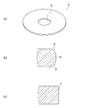
- (a) is a perspective view of an example of a glass plate manufactured by a method for manufacturing a glass plate according to an embodiment
- (b) is an example of a cross-sectional shape of an end face of the glass plate after formation of a chamfered surface
- (c) is a diagram showing an example of the cross-sectional shape of the end face of the glass plate before the formation of the chamfered surface.
- a glass plate manufactured by the method for manufacturing a glass plate according to one embodiment is a ring-shaped glass plate whose end face is chamfered, and is used, for example, as a glass substrate for a magnetic disk.
- FIG. 1(a) is a perspective view of an example of an annular glass plate manufactured by a method for manufacturing a glass plate according to an embodiment.
- a ring-shaped glass plate is a glass plate having a circular outer periphery. Further, the annular glass plate has an inner circumference with an inner hole concentric with the circular circle. Moreover, the ring-shaped glass plate has a pair of main surfaces.
- the glass plate 1 shown in FIG. 1(a) can be used as a magnetic disk glass substrate.
- the size of the magnetic-disk glass substrate is not limited, but is, for example, the size of a magnetic-disk glass substrate having a nominal diameter of 2.5 inches or 3.5 inches.
- the outer diameter (diameter) is 55 to 70 mm, for example, the outer diameter is 65 mm or 67 mm, the inner hole diameter (diameter) is 20 mm, and the plate thickness is 0.3 mm. ⁇ 1.3 mm.
- a magnetic disk glass substrate having a nominal diameter of 3.5 inches has an outer diameter of 85 to 100 mm, for example, an outer diameter of 95 mm, 96 mm or 97 mm, an inner hole diameter of 25 mm, and a plate thickness of 0.3 mm. ⁇ 1.3 mm.
- the glass plate 1 shown in FIG. 1(a) has a chamfered surface (or a chamfered surface) by chamfering the corners between the end surface (inner peripheral end surface and/or outer peripheral end surface) and the main surface by shape processing of the end surface. part) is formed.
- the chamfered portion which is a chamfered area, is not a flat surface as described later, the chamfered portion is called a chamfered surface.
- FIG. 1(b) is a diagram showing an example of the cross-sectional shape of the entire end face with chamfered corners according to the present invention.
- the end face with two chamfered corners has two chamfered surfaces 5 .
- the cross-sectional shape is the shape of the glass plate 1 passing through the center of the annular shape of the glass plate 1 along the radial direction and the plate thickness direction.
- the cross-sectional shape of the chamfered surface 5 is a curved surface formed by a smooth curved line convex outward on the surface of the glass plate.
- the cross-sectional shape of the end face after chamfering (already chamfered) is, as in the example shown in FIG.
- the side wall surface 6 existing in the 1 may form one curved surface as a whole.
- the cross-sectional shape shown in FIG. It may be formed in a linear shape orthogonal to the main surface or in a curved curved shape different from the chamfered surface.
- the chamfered length in the radial direction of the glass plate 1 after the chamfering process is defined as the difference between the radius of the position where the end face protrudes most in the radial direction and the radius of the position where the main surface starts to incline toward the end face. and can be, for example, 30-200 ⁇ m.
- the main surface of the glass plate 1 is ground and/or polished as necessary, and then a magnetic film is formed on the main surface of the glass plate 1 to form a magnetic disk. made.
- FIG. 1(c) is a diagram showing an example of the cross-sectional shape of the inner peripheral end face 7 of the glass plate (hereinafter also referred to as the glass base plate) before the formation of the chamfered surface.
- the glass base plate By irradiating the inner peripheral end surface 7 with a laser beam, which will be described later, the corner portion of the boundary between the main surface of the glass base plate and the inner peripheral end surface 7 is heated to a temperature equal to or higher than the softening point and partially melted, for example, the chamfering process is performed by forming a curved surface as shown in FIG. 1(b).
- the inner peripheral end surface 7 of the glass plate before forming the chamfered surface is a surface substantially perpendicular to the main surface of the glass plate.
- the outer peripheral end face 7 Like the inner peripheral end face 7, the outer peripheral end face also has a surface substantially orthogonal to the main surface of the glass base plate. By irradiating such a surface with a laser beam, which will be described later, the corner between the main surface and the inner peripheral end face 7 is chamfered, for example, a chamfered surface 5 shown in FIG. 1(b) is formed. can be done. Note that the cross-sectional shape of the inner peripheral end face 7 shown in FIG. 1(c) is an example, and is not limited to a shape substantially perpendicular to the main surface.
- the cross-sectional shape of the inner peripheral end surface 7 may be inclined with respect to the main surface, but the cross-sectional shape of the inner peripheral end surface 7 is the center parallel to the main surface passing through the center of the thickness in the thickness direction of the glass base plate before the chamfered surface 5 is formed. If it is axisymmetric with respect to a line (described later), the cross-sectional shape of the inner peripheral end face after irradiation with the laser beam, that is, the inner peripheral end face after the formation of the chamfered surface 5, tends to be similarly axisymmetric. preferable.
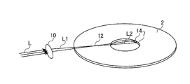
- FIG.2 and FIG.3 is a figure explaining the irradiation of the laser beam performed in the manufacturing method of the glass plate 1 which is one Embodiment.
- the chamfered surface 5 can be formed on the inner peripheral end surface 7 and the surface roughness of the inner peripheral end surface 7 or the chamfered surface 5 can be reduced.
- the surface roughness of the inner peripheral end surface (chamfered surface 5 and/or side wall surface 6) after irradiation with laser light L is 50 nm or less in arithmetic mean roughness Ra (JIS B0601 2001) and/or maximum height Rz (JIS B0601 2001) is 500 nm or less.
- the surface roughness can be measured, for example, with a laser microscope.
- the inner peripheral end face 7 is irradiated with the laser light L so that the laser light L moves relative to the inner peripheral end face 7 in the circumferential direction of the glass base plate 2 .
- the laser light L is passed through the condensing position 12 by the condensing lens 10 to change from the converging light L1 to the diffused light L2, and the diffused light L2 is inclined with respect to the main surface of the glass base plate 2.
- the inner peripheral end surface 7 is irradiated from the direction shown.
- the laser light L is condensed by the condensing lens 10 and then diffused into the diffused light L2, and the diffused light L2 is projected onto the inner peripheral end surface 7 from a direction inclined with respect to the main surface. to irradiate.
- Irradiating the diffused light L2 from a direction inclined with respect to the main surface means that the central axis of the light flux of the diffused light L2 is inclined with respect to the main surface.
- the laser light L condensed by the condensing lens 10 passes through the condensing position (focus) 12 and becomes the diffused light L2, and the light reaches the inner peripheral end face 7. to irradiate.
- the convergence and diffusion of the laser light L need only occur at least in the plate thickness direction of the glass base plate.
- the luminous flux of the diffused light L2 is small near the condensing position 12.
- the part of the glass base plate 2 facing the irradiation position 14 of the laser beam L on the inner peripheral end face 7 across the center of the ring-shaped glass base plate 2 becomes an obstacle in the optical path. is scattered, or even if it is transmitted through the opposing portion, the light intensity of the transmitted light is reduced, making it difficult to form the chamfered surface 5, or making the cross-sectional shape of the inner peripheral end surface a line-symmetrical shape. strength cannot be guaranteed.
- the luminous flux can be reduced near the place where the glass plate 2 tends to become an obstacle (position A described later). .
- the temperature of the corners on both sides in the thickness direction of the inner peripheral end surface 7 at the condensing position 12 is approximately approach the same temperature.
- the cross-sectional shape of the inner peripheral end surface is a line-symmetrical shape, and the desired shape can be easily obtained. That is, the cross-sectional shape of the inner peripheral end face can be made symmetrical with respect to the center line passing through the center in the thickness direction of the glass plate 1 and parallel to the main surface.
- the line-symmetrical shape means the contour of the end face at each position in the thickness direction when the contour line of the cross-sectional shape is folded back with respect to the center line that passes through the center in the thickness direction of the glass plate 1 and is parallel to the main surface. It means that the maximum deviation of the lines in the direction parallel to the main surface is 30 [ ⁇ m] or less. More preferably, the maximum deviation is 20 [ ⁇ m] or less. If the maximum deviation exceeds 30 [ ⁇ m], the posture of the glass plate 1 becomes unstable when holding the inner hole 3 in a film forming apparatus for forming a magnetic film or the like for functioning as a magnetic disk. Troubles such as cracking and dropping of the plate 1 are more likely to occur.
- the line-symmetrical shape with respect to the cross-sectional shape of the inner peripheral end face of the glass plate 2 means that the maximum deviation is 30 [ ⁇ m] or less when the glass plate 2 is used instead of the glass plate 1 .
- the condensing position 12 is positioned on the inner peripheral end face 7 of the diffused light L2. is preferably set in an area centered above the position of the inner peripheral end surface 7 (hereinafter also referred to as "position A") facing the irradiation position 14 of the inner hole 3 across the center.
- the condensing position 12 may be variously adjusted in consideration of the specifications of the laser light L (inclined angle ⁇ , diffusion angle ⁇ , etc.), the plate thickness of the glass base plate 2, the diameter of the inner hole 3, and the like.
- the condensing position 12 is preferably set above the plane including the main surface radially outward of the position A. As shown in FIG. By doing so, the effect of sufficiently widening the area (spot diameter) of the diffused light L2 at the irradiation position 14 can also be obtained.
- the condensing position 12 is preferably spaced radially outward from the position A by more than 0 mm in plan view.
- the distance is more preferably 10 mm or more, and even more preferably 20 mm or more. Although it is not necessary to set an upper limit for the distance, it may be set to 300 mm or less, for example, in order to avoid an increase in the size of the apparatus.
- plane view means viewing from a direction perpendicular to the main surface of the glass plate.
- the laser light L can be obtained by being emitted from a laser oscillation device (not shown).
- a laser oscillation device not shown
- the center of the annular shape of the glass plate 2 is A method can be used in which the glass base plate 2 is rotated while being aligned with the rotation center of the turntable and fixed.
- the laser light L may be scanned along the inner peripheral end face 7 of the glass plate 2 by irradiating the laser light L onto the inner peripheral end face 7 of the glass plate 2 that rotates together with the turntable.
- the relative moving speed between the laser beam L and the inner peripheral end face 7 of the glass base plate 2 may be, for example, 0.7 to 100 [mm/sec].
- the laser light L CO 2 laser light can be used, for example. It is preferable that the wavelength of the CO 2 laser beam is 3 ⁇ m or more.
- Laser light L may be other than CO 2 laser light as long as it has an oscillation wavelength that is absorbed by glass. wavelength of about 2.94 ⁇ m).
- the size and shape of the beam (irradiation spot) of the laser beam L at the irradiation position on the inner peripheral end face 7 may be, for example, a circular shape with a diameter of 1 to 10 mm, but it may be an elliptical shape with an area equivalent to this. .
- the size and shape of the irradiation spot may be appropriately selected according to the plate thickness of the glass plate 2 to be chamfered. is preferably larger than the plate thickness of the glass base plate 2 in .
- the average power density of the luminous flux at the irradiation position of the laser light L may be, for example, 1 to 30 [W/mm 2 ].
- the average power density is obtained by dividing the total power [W] of the laser beam L into the area [mm 2 ] of the luminous flux on the surface including the portion of the inner peripheral end face 7 irradiated with the laser beam L (that is, the area of the luminous flux [mm 2 ]) (that is, a part of the luminous flux (If it protrudes from the peripheral end face 7, the area of the protruding portion is also included.).
- the total power of the laser beam L may be, for example, 10 to 300 [W].
- the central axis of the luminous flux of the diffused light L2 is positioned above the center of the annular shape of the glass base plate 2 (on the central axis of the glass base plate 2 perpendicular to the main surface). It is preferable to irradiate the laser light L so as to pass through the position above the glass base plate 2). By doing so, the angle of incidence of the laser light L on the inner peripheral end surface 7 approaches the vertical, so that the energy loss due to the reflection of the laser light L can be minimized, so that the chamfered surface 5 can be formed efficiently. can.
- a heating method for example, a heater or the like may be arranged around the glass base plate 2 to raise the temperature of the entire glass base plate 2 .
- a heater for example, a halogen lamp heater, a carbon heater, an infrared heater such as a sheathed heater, or the like can be used.
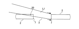
- FIG. 4 is a diagram for explaining laser light irradiation performed in a method for manufacturing the glass plate 1 using a method different from the present invention.
- FIG. 4 shows an example of irradiating the inner peripheral end face 7 with the convergent light L1. Since the luminous flux of the convergent light L1 spreads as it moves away from the irradiation position 14 of the inner peripheral end face 7, the facing portion 20 of the glass base plate 2 facing the irradiation position 14 of the laser light L on the inner peripheral end face 7 becomes an obstacle.
- the intensity of the transmitted light is reduced, making it difficult to form the chamfered surface 5, or making the cross-sectional shape of the inner peripheral end surface a line-symmetrical shape.
- the light intensity cannot be secured.
- the inclination angle ⁇ (see FIG. 3) of the central axis of the luminous flux of the diffused light L2 (laser light) with respect to the main surface is preferably small in order to make the cross-sectional shape of the inner peripheral end surface a line-symmetrical shape, as described above. Specifically, it is preferably 20 degrees or less, more preferably 15 degrees or less, and even more preferably 10 degrees or less. Moreover, it is preferable to irradiate the diffused light L2 only from one main surface side of the glass base plate 2 from a direction inclined with respect to this main surface.
- the device configuration can be greatly simplified.
- the minimum value of the inclination angle ⁇ is not particularly limited, it is preferably 1 degree or more, for example. If the tilt angle ⁇ is less than 1 degree, it may be difficult to adjust the optical system during mass production.
- the diffusion angle ⁇ of the laser light L (see FIG.
- the angle indicating the narrowing or spreading of the light flux when condensing or diffusing is 20 degrees in full-width display from the viewpoint of making it easier to reduce the above-described inclination angle ⁇ . It is preferably 10 degrees or less, more preferably 10 degrees or less, and even more preferably 5 degrees or less. Further, the smaller the diffusion angle ⁇ , the easier it is to move the position of the laser oscillation device and/or optical system components such as lenses relatively far from the glass base plate 2, which is the object to be processed. There is also the advantage that the degree of freedom in designing auxiliary devices that are loaded/unloaded to/from the device is increased.
- the minimum value of the diffusion angle ⁇ is not particularly limited, it is preferably 0.5 degrees or more in full-width display, for example. If the diffusion angle ⁇ is less than 0.5 degrees, the size of the device may increase.
- the manufacturing method is not particularly limited.
- a plurality of disc-shaped glass plates having inner holes can be taken out from a wide sheet-like glass plate manufactured by the float method or the down-draw method.
- the method of extracting a disk-shaped glass plate from a wide sheet-shaped glass plate may be performed by cutting using a known scriber, or by irradiating the glass plate with a laser beam to form a circular defect. It may be cut out in an annular shape.
- a glass plate processing apparatus which is an embodiment, is configured to perform the above-described glass plate manufacturing method.
- the glass plate processing apparatus includes a laser beam irradiation device.
- the laser light irradiation device has a laser oscillation device and an optical system component.
- the optical system components include lenses including the condensing lens 10 and the like.
- the glass plate processing apparatus may include a holding portion that holds the glass base plate by fixing or placing it, and a rotation mechanism for rotating the holding portion. Further, the glass plate processing apparatus may be provided with a turntable in which the functions of the holding part and the rotating mechanism are integrated.
- the magnetic-disk glass substrate is manufactured from the glass plate 1 having the chamfered surface 5
- various treatments described below are performed so that the magnetic-disk glass substrate, which is the final product, has suitable properties.
- the main surface of the glass plate 1 is ground and polished.
- the glass plate 1 is ground and/or polished.
- polishing is performed after grinding.
- a pair of main surfaces of the glass plate 1 are ground using a double-side grinding device equipped with a planetary gear mechanism. Specifically, both main surfaces of the glass plate 1 are ground while holding the outer peripheral end face of the glass plate 1 in holding holes provided in a holding member (grinding carrier) of the double-sided grinding apparatus.
- the double-sided grinding apparatus has a pair of upper and lower surface plates (an upper surface plate and a lower surface plate), and a glass plate 1 is sandwiched between the upper surface plate and the lower surface plate.
- the glass plate 1 and each surface plate are moved relatively to each main surface of the glass plate 1.
- a grinding member in which fixed abrasive grains having fine diamond particles fixed with a resin are formed in a sheet shape can be mounted on a surface plate for grinding.
- the pair of main surfaces of the glass plate 1 after grinding is subjected to first polishing. Specifically, both main surfaces of the glass plate 1 are polished while holding the outer peripheral end face of the glass plate 1 in holding holes provided in a polishing carrier of the double-sided polishing apparatus.
- the purpose of the first polishing is to remove scratches and distortions remaining on the main surface after grinding, or to adjust fine surface unevenness (micro-waviness, roughness).
- the glass plate 1 is polished while applying polishing slurry using a double-side polishing machine having the same configuration as the double-side polishing machine used in the above-described grinding process using fixed abrasive grains.
- a polishing slurry containing free abrasive grains is used in the first polishing process.
- loose abrasive grains used in the first polishing for example, abrasive grains such as cerium oxide or zirconia are used.
- the glass plate 1 is sandwiched between a pair of upper and lower surface plates as in the double-side polishing apparatus.
- a flat plate polishing pad (for example, a resin polisher) having an annular shape as a whole is attached to the upper surface of the lower surface plate and the bottom surface of the upper surface plate. Then, by moving either or both of the upper surface plate and the lower surface plate, the glass plate 1 and each surface plate are relatively moved to polish both main surfaces of the glass plate 1. .
- the size of the abrasive grains is preferably in the range of 0.5 to 3 ⁇ m in average particle diameter (D50).
- the glass plate 1 may be chemically strengthened.
- the chemical strengthening liquid for example, a mixed molten liquid of potassium nitrate and sodium nitrate or the like is used, and the glass plate 1 is immersed in the chemical strengthening liquid. Thereby, a compressive stress layer can be formed on the surface of the glass plate 1 by ion exchange.
- the glass plate 1 is subjected to the second polishing.
- the purpose of the second polishing treatment is to mirror polish the main surface.
- a double-sided polishing apparatus having the same structure as the double-sided polishing apparatus used in the first polishing is used. Specifically, both main surfaces of the glass plate 1 are polished while holding the outer peripheral end face of the glass plate 1 in holding holes provided in a polishing carrier of the double-sided polishing apparatus.
- the type and particle size of free abrasive grains are different from those in the first polishing treatment, and the hardness of the resin polisher is different. It is preferable that the hardness of the resin polisher is lower than that during the first polishing treatment.
- a polishing liquid containing colloidal silica as free abrasive grains is supplied between the polishing pad of the double-sided polishing apparatus and the main surface of the glass plate 1, and the main surface of the glass plate 1 is polished.
- the size of the abrasive grains used in the second polishing is preferably within the range of 5 to 50 nm in average grain size (d50).
- the roughness of the pair of main surfaces of the glass plate 1 after the second polishing is preferably 0.2 nm or less in arithmetic mean roughness Ra (JIS B0601 2001). The surface roughness can be measured by AFM, for example.
- the chemical strengthening treatment is necessary or not may be appropriately selected in consideration of the glass composition and necessity.
- another polishing treatment may be added, and the two main surfaces may be polished with one polishing treatment.
- the order of the above processes may be changed as appropriate. In this way, after the glass plate 1 having the chamfered surface 5 formed on the end face is produced by irradiating the end face with the above-described laser light L (diffused light L2), the main surface of the glass plate 1 is ground or polished to obtain a magnetic field.
- a magnetic disk glass substrate satisfying the conditions required for a disk glass substrate is manufactured. Thereafter, a magnetic disk is manufactured by forming at least a magnetic film on the main surface of the magnetic disk glass substrate.
- the end face (inner peripheral end face and/or outer peripheral end face) of the glass plate 1 may be polished.
- the arithmetic mean roughness Ra of the end face of the glass plate 1 on which the chamfered surface 5 is formed by irradiation with the laser beam L is 50 nm or less and/or Rz is 500 nm or less. Therefore, the time required for end surface polishing can be shortened.
- a polishing brush method may be used in which the end face is polished using a polishing brush while free abrasive grains are supplied to the end face.
- the main surface of the glass plate 1 without polishing the end face. That is, it is preferable to grind or polish the main surface of the glass plate 1 while maintaining the surface roughness of the end face of the glass plate 1 at the surface roughness of the end face obtained by the irradiation of the laser light L. Since the surface roughness of the end face formed by the irradiation of the laser light L performed in this embodiment is small, it may be said that the formation of the chamfered surface 5 also serves as end face polishing.
- the above-mentioned end face polishing refers to additional end face polishing other than the end face polishing performed simultaneously with the formation of the chamfered surface 5 .
- Amorphous glass such as aluminosilicate glass, soda-lime glass, and borosilicate glass can be used as the glass material for the glass plate 1 and the glass base plate 2 serving as the base plate.
- the glass material is preferably amorphous glass in that a magnetic disk glass substrate having excellent flatness of the main surface and excellent substrate strength can be produced.
- the glass transition temperature Tg of the glass plate 1 and the glass base plate 2 is preferably 450 to 850° C. so that they can withstand the heating during the formation of the magnetic film.
- Example 1 A simulation was conducted to confirm whether or not the luminous flux is blocked by the glass plate when the conditions for irradiating the inner peripheral end face of the annular glass plate with the laser light L are variously changed.
- the irradiation spot diameter was the maximum length of the cross section of the luminous flux in the plate thickness direction of the glass plate at the irradiation position on the inner peripheral end surface (that is, the central axis of the laser beam L with the inclination angle ⁇ not the length taken from the perpendicular section). Also, the center of the irradiation spot diameter was aligned with the center of the plate thickness of the inner peripheral end surface.
- ⁇ Evaluation result A case where the light flux is blocked by the glass plate even a little is BAD (that is, the case as shown in Fig. 4), and a case that the light flux is not blocked at all is judged as GOOD (that is, the case as shown in Fig. 3).
- the laser light can be irradiated without the light flux being blocked by using the divergent light.
- the position of the focal point is located radially outside the inner diameter end of the glass base plate in plan view. That is, it is positioned radially outside of the aforementioned "position A".
- the degree of freedom in designing ancillary equipment for loading/unloading the glass base plate to/from the laser beam irradiation equipment is increased, which is preferable.
- Example 2 Using conditions 10, 12, and 14 in Table 1, the inner peripheral end surface of the glass plate was actually chamfered.
- the shape of the annular glass base plate was the same as in Experimental Example 1, except that the thickness was changed to 0.7 mm.
- Amorphous aluminosilicate glass having a glass transition point of about 500° C. was used as the material of the glass base plate.
- a CO 2 laser was used as the laser light L.
- the entire main surface of the glass plate 2 was heated with an infrared heater.
- Other conditions and methods for performing irradiation were appropriately adjusted with reference to the above-described embodiment so that the inner peripheral end face after chamfering had the same cross-sectional shape as in FIG. 1(b).
- the inner peripheral end surface of the obtained glass plate had a cross-sectional shape similar to that of FIG. 1(b), and a chamfered surface was formed.
- the surface roughness of the inner peripheral end faces thereof was 50 nm or less in terms of arithmetic mean roughness Ra (measured with a laser microscope).
- the shape was axisymmetric with respect to a center line passing through the center of the glass plate in the thickness direction and parallel to the main surface.
Landscapes
- Chemical & Material Sciences (AREA)
- Engineering & Computer Science (AREA)
- Organic Chemistry (AREA)
- Materials Engineering (AREA)
- Chemical Kinetics & Catalysis (AREA)
- Geochemistry & Mineralogy (AREA)
- General Chemical & Material Sciences (AREA)
- Life Sciences & Earth Sciences (AREA)
- Manufacturing & Machinery (AREA)
- Optics & Photonics (AREA)
- Physics & Mathematics (AREA)
- Health & Medical Sciences (AREA)
- Toxicology (AREA)
- Ceramic Engineering (AREA)
- Inorganic Chemistry (AREA)
- Mechanical Engineering (AREA)
- Plasma & Fusion (AREA)
- Manufacturing Of Magnetic Record Carriers (AREA)
Abstract
Priority Applications (3)
| Application Number | Priority Date | Filing Date | Title |
|---|---|---|---|
| JP2022578529A JP7458511B2 (ja) | 2021-01-28 | 2022-01-28 | ガラス板の製造方法、磁気ディスク用ガラス基板の製造方法、磁気ディスクの製造方法、およびガラス板の処理装置 |
| US18/276,685 US20240101473A1 (en) | 2021-01-28 | 2022-01-28 | Method for manufacturing glass plate, method for manufacturing glass substrate for magnetic disk, method for manufacturing magnetic disk, and apparatus for processing glass plate |
| CN202280009463.7A CN116745244A (zh) | 2021-01-28 | 2022-01-28 | 玻璃板的制造方法、磁盘用玻璃基板的制造方法、磁盘的制造方法和玻璃板的处理装置 |
Applications Claiming Priority (2)
| Application Number | Priority Date | Filing Date | Title |
|---|---|---|---|
| VN1202100461 | 2021-01-28 | ||
| VN1-2021-00461 | 2021-01-28 |
Publications (1)
| Publication Number | Publication Date |
|---|---|
| WO2022163841A1 true WO2022163841A1 (fr) | 2022-08-04 |
Family
ID=82654695
Family Applications (1)
| Application Number | Title | Priority Date | Filing Date |
|---|---|---|---|
| PCT/JP2022/003442 WO2022163841A1 (fr) | 2021-01-28 | 2022-01-28 | Procédé de fabrication d'une plaque en verre, procédé de fabrication d'un substrat en verre pour disque magnétique, procédé de fabrication d'un disque magnétique, et appareil de traitement de plaque de verre |
Country Status (4)
| Country | Link |
|---|---|
| US (1) | US20240101473A1 (fr) |
| JP (1) | JP7458511B2 (fr) |
| CN (1) | CN116745244A (fr) |
| WO (1) | WO2022163841A1 (fr) |
Citations (4)
| Publication number | Priority date | Publication date | Assignee | Title |
|---|---|---|---|---|
| JP2002150546A (ja) * | 2000-11-06 | 2002-05-24 | Nippon Sheet Glass Co Ltd | 情報記録媒体用ガラス基板の製造方法、及び該製造方法により製造された情報記録媒体用ガラス基板、並びに情報記録媒体 |
| WO2014051127A1 (fr) * | 2012-09-28 | 2014-04-03 | Hoya株式会社 | Procédé de fabrication de substrat de verre pour disque magnétique |
| JP2018519229A (ja) * | 2015-03-24 | 2018-07-19 | コーニング インコーポレイテッド | ディスプレイガラス組成物のレーザ切断及び加工 |
| WO2020262702A1 (fr) * | 2019-06-28 | 2020-12-30 | Hoya株式会社 | Procédé de fabrication de plaque de verre et procédé de fabrication de disque magnétique |
Family Cites Families (1)
| Publication number | Priority date | Publication date | Assignee | Title |
|---|---|---|---|---|
| JP7227273B2 (ja) * | 2018-11-30 | 2023-02-21 | Hoya株式会社 | ガラス板の製造方法、ガラス板の面取り方法、および磁気ディスクの製造方法 |
-
2022
- 2022-01-28 CN CN202280009463.7A patent/CN116745244A/zh active Pending
- 2022-01-28 WO PCT/JP2022/003442 patent/WO2022163841A1/fr active Application Filing
- 2022-01-28 US US18/276,685 patent/US20240101473A1/en active Pending
- 2022-01-28 JP JP2022578529A patent/JP7458511B2/ja active Active
Patent Citations (4)
| Publication number | Priority date | Publication date | Assignee | Title |
|---|---|---|---|---|
| JP2002150546A (ja) * | 2000-11-06 | 2002-05-24 | Nippon Sheet Glass Co Ltd | 情報記録媒体用ガラス基板の製造方法、及び該製造方法により製造された情報記録媒体用ガラス基板、並びに情報記録媒体 |
| WO2014051127A1 (fr) * | 2012-09-28 | 2014-04-03 | Hoya株式会社 | Procédé de fabrication de substrat de verre pour disque magnétique |
| JP2018519229A (ja) * | 2015-03-24 | 2018-07-19 | コーニング インコーポレイテッド | ディスプレイガラス組成物のレーザ切断及び加工 |
| WO2020262702A1 (fr) * | 2019-06-28 | 2020-12-30 | Hoya株式会社 | Procédé de fabrication de plaque de verre et procédé de fabrication de disque magnétique |
Also Published As
| Publication number | Publication date |
|---|---|
| JP7458511B2 (ja) | 2024-03-29 |
| CN116745244A (zh) | 2023-09-12 |
| US20240101473A1 (en) | 2024-03-28 |
| JPWO2022163841A1 (fr) | 2022-08-04 |
Similar Documents
| Publication | Publication Date | Title |
|---|---|---|
| JP7311702B2 (ja) | ガラス板および磁気ディスク | |
| US6845635B2 (en) | Method of manufacturing glass substrate for information recording media, glass substrate for information recording media manufactured using the method, and information recording medium using the glass substrate | |
| JP7411660B2 (ja) | 円環形状のガラス板の製造方法、磁気ディスク用ガラス基板の製造方法、磁気ディスクの製造方法、円環形状のガラス板、磁気ディスク用ガラス基板、及び磁気ディスク | |
| JP6783401B2 (ja) | 円盤形状のガラス素板の製造方法、及び磁気ディスク用ガラス基板の製造方法 | |
| JP7227273B2 (ja) | ガラス板の製造方法、ガラス板の面取り方法、および磁気ディスクの製造方法 | |
| US12084376B2 (en) | Method for manufacturing glass substrate and method for manufacturing magnetic disk | |
| JP7366141B2 (ja) | ガラス板の製造方法、磁気ディスク用ガラス基板の製造方法、および磁気ディスクの製造方法 | |
| WO2022163841A1 (fr) | Procédé de fabrication d'une plaque en verre, procédé de fabrication d'un substrat en verre pour disque magnétique, procédé de fabrication d'un disque magnétique, et appareil de traitement de plaque de verre | |
| WO2023171824A1 (fr) | Procédé de fabrication de substrat de verre discoïde, procédé de fabrication de substrat de verre annulaire, procédé de fabrication de substrat de verre à usage de disque magnétique, substrat de verre discoïde, substrat de verre annulaire et substrat de verre à usage de disque magnétique | |
| JP7523579B2 (ja) | ガラス板の製造方法、磁気ディスク用ガラス基板の製造方法、磁気ディスクの製造方法、及び円環形状のガラス板 | |
| WO2023282252A1 (fr) | Procédé de fabrication pour substrat en verre et substrat en verre en forme de disque | |
| CN118830022A (zh) | 盘状玻璃基板制造方法、环形玻璃基板制造方法、磁盘用玻璃基板制造方法、盘状玻璃基板、环形玻璃基板和磁盘用玻璃基板 |
Legal Events
| Date | Code | Title | Description |
|---|---|---|---|
| 121 | Ep: the epo has been informed by wipo that ep was designated in this application |
Ref document number: 22746060 Country of ref document: EP Kind code of ref document: A1 |
|
| WWE | Wipo information: entry into national phase |
Ref document number: 202280009463.7 Country of ref document: CN |
|
| ENP | Entry into the national phase |
Ref document number: 2022578529 Country of ref document: JP Kind code of ref document: A |
|
| WWE | Wipo information: entry into national phase |
Ref document number: 18276685 Country of ref document: US |
|
| NENP | Non-entry into the national phase |
Ref country code: DE |
|
| WWE | Wipo information: entry into national phase |
Ref document number: 11202305378X Country of ref document: SG |
|
| 122 | Ep: pct application non-entry in european phase |
Ref document number: 22746060 Country of ref document: EP Kind code of ref document: A1 |