WO2022162930A1 - Rotor of rotating electrical machine and rotating electrical machine - Google Patents
Rotor of rotating electrical machine and rotating electrical machine Download PDFInfo
- Publication number
- WO2022162930A1 WO2022162930A1 PCT/JP2021/003479 JP2021003479W WO2022162930A1 WO 2022162930 A1 WO2022162930 A1 WO 2022162930A1 JP 2021003479 W JP2021003479 W JP 2021003479W WO 2022162930 A1 WO2022162930 A1 WO 2022162930A1
- Authority
- WO
- WIPO (PCT)
- Prior art keywords
- rotor
- stepped portion
- axis
- bending
- pole
- Prior art date
Links
- 238000005452 bending Methods 0.000 claims abstract description 132
- 238000005457 optimization Methods 0.000 abstract description 2
- 230000005284 excitation Effects 0.000 description 19
- 230000000694 effects Effects 0.000 description 7
- 238000010586 diagram Methods 0.000 description 6
- 238000005516 engineering process Methods 0.000 description 1
- 238000000605 extraction Methods 0.000 description 1
- 238000000034 method Methods 0.000 description 1
- 230000004048 modification Effects 0.000 description 1
- 238000012986 modification Methods 0.000 description 1
- 230000010355 oscillation Effects 0.000 description 1
- 230000001629 suppression Effects 0.000 description 1
Images


Classifications
-
- H—ELECTRICITY
- H02—GENERATION; CONVERSION OR DISTRIBUTION OF ELECTRIC POWER
- H02K—DYNAMO-ELECTRIC MACHINES
- H02K1/00—Details of the magnetic circuit
- H02K1/06—Details of the magnetic circuit characterised by the shape, form or construction
- H02K1/22—Rotating parts of the magnetic circuit
- H02K1/26—Rotor cores with slots for windings
-
- H—ELECTRICITY
- H02—GENERATION; CONVERSION OR DISTRIBUTION OF ELECTRIC POWER
- H02K—DYNAMO-ELECTRIC MACHINES
- H02K7/00—Arrangements for handling mechanical energy structurally associated with dynamo-electric machines, e.g. structural association with mechanical driving motors or auxiliary dynamo-electric machines
- H02K7/08—Structural association with bearings
- H02K7/083—Structural association with bearings radially supporting the rotary shaft at both ends of the rotor
-
- H—ELECTRICITY
- H02—GENERATION; CONVERSION OR DISTRIBUTION OF ELECTRIC POWER
- H02K—DYNAMO-ELECTRIC MACHINES
- H02K5/00—Casings; Enclosures; Supports
- H02K5/24—Casings; Enclosures; Supports specially adapted for suppression or reduction of noise or vibrations
-
- H—ELECTRICITY
- H02—GENERATION; CONVERSION OR DISTRIBUTION OF ELECTRIC POWER
- H02K—DYNAMO-ELECTRIC MACHINES
- H02K7/00—Arrangements for handling mechanical energy structurally associated with dynamo-electric machines, e.g. structural association with mechanical driving motors or auxiliary dynamo-electric machines
- H02K7/003—Couplings; Details of shafts
Definitions
- This application relates to a rotor of a rotating electrical machine and a rotating electrical machine.
- a two-pole rotor of a rotary electric machine such as a turbine generator
- a plurality of rotor slots are provided in a rotor core in a circumferential direction around a rotation axis. Coil is included.
- a rotor wedge for holding the rotor coil is inserted in the outer diameter side of the rotor slot.
- the rotor slots of the two-pole rotor are not evenly arranged in the circumferential direction of 360 degrees of the rotor core, but are concentrated on the inter-polar shaft side. That is, this means that the rotor core has asymmetry in bending stiffness about the inter-pole axis and bending stiffness about the center pole axis. This asymmetry produces changes in gravitational deflection that have twice the frequency with respect to rotational speed (double frequency oscillation).
- a plurality of cross slots are provided along the direction of the rotation axis, and the asymmetry of the bending rigidity of the rotor core can be adjusted by adjusting the pitch of the cross slots in the direction of the rotation axis or the depth of cut of the cross slots.
- the rotor coils in the rotor slots are held by the rotor wedges, but when the rotor rotates, centrifugal forces act on the rotor coils and the rotor wedges, so these are especially the interpole shaft It is constrained in the direction and contributes to the increase in bending stiffness around the pole central axis. That is, the bending stiffness around the pole center axis with respect to the bending stiffness around the axis between poles of the rotor main section including the rotor core, rotor coils, rotor wedges, and cross slots is defined as the asymmetry factor of the bending stiffness of the rotor main section.
- the bending stiffness around the pole center axis increases as the rotational speed increases, so the asymmetry rate of the bending stiffness of the main part of the rotor also increases. Therefore, it is necessary to determine the pitch of the cross slots in the rotation axis direction and the depth of cut of the cross slots in consideration of the rotation speed dependence of the asymmetry rate.
- the rated rotation speed of a two-pole rotor of a rotary electric machine such as a turbine generator is 3,000 rpm or 3,600 rpm, and a plurality of double frequency Pass through the critical speed of the bending vibration mode of vibration.
- the primary bending vibration mode has one antinode between two bearings, and the tertiary bending vibration mode has three antinodes between two bearings. be.
- the rotor main section corresponds to the position of the antinode of the vibration mode in any bending vibration mode. ing.
- the rotor of a rotating electric machine such as a turbine generator has a stepped portion of the rotor on the side of the exciter that has asymmetry in bending rigidity in addition to the main portion of the rotor. Only by optimizing the stiffness asymmetry, double frequency vibration may not be sufficiently suppressed over the entire operating speed range.
- the rotor core of rotating electric machines plays the role of an electromagnet, and the rotor coil is connected to an external power supply.
- the rotor coil wound around the rotor core is adjacent to the rotor core in the direction of the rotation axis and has an outer diameter smaller than that of the rotor core. through and connected to the exciter.
- the rotor coil passes through a rotor coil lead groove provided over the rotation axis direction at the outer diameter position of the rotor stepped portion on the side of the excitation device in the axial direction of the pole, and passes through the rotor coil lead groove to the rotation of the excitation device side.
- a radial lead groove provided parallel to the pole center axis toward the inner diameter side of the child stepped portion, it passes through an axial lead groove provided along the central axis of the stepped portion of the rotor on the side of the exciter.
- Both the rotor coil lead groove and the radial lead groove reduce the bending rigidity of the rotor stepped portion on the exciter side around the inter-polar axis.
- the bending rigidity of the stepped portion of the rotor on the side of the exciter is asymmetry also acts as an excitation source for double frequency vibration.
- the asymmetry of the bending rigidity of the stepped portion of the rotor on the side of the exciter is Since the stepped portion of the rotor on the side of the exciter exists at the position of the antinode of the vibration mode, it acts as an excitation source of the double frequency vibration.
- Patent Document 1 aims to optimize the asymmetry of the bending rigidity of the main portion of the rotor. was inadequate for
- the present application has been made to solve the above-described problems, and is directed to suppressing double-frequency vibration in a rotor of a rotating electric machine, which is caused by the excitation source of the asymmetry of the bending rigidity of the stepped portion of the rotor. It is an object of the present invention to provide a rotor that is effective even against
- the stepped portion of the rotor adjusts the bending rigidity around the pole center axis, and the bending rigidity around the pole center axis and the bending rigidity around the pole center axis are asymmetrical.
- At least one notch groove is provided in the rotation axis direction of the stepped portion of the rotor.
- the cross slots provided in the rotor core adjust the asymmetry of the bending rigidity of the rotor main portion, and the notched grooves provided in the stepped portion of the rotor
- optimization is achieved by combining the asymmetry of the bending rigidity of the main portion of the rotor and the asymmetry of the bending rigidity of the stepped portion of the rotor. Therefore, it is possible to reduce the excitation force existing at the position of the antinode of the vibration mode for each bending vibration mode of the double frequency vibration. There is an effect that the vibration of each bending vibration mode can be suppressed.
- FIG. 2 is an external side view showing the configuration of the two-pole rotor of the rotary electric machine according to Embodiment 1;
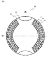
- FIG. 2 is a cross-sectional view showing the configuration of the rotor main part when viewed from the direction of the arrow in the AA section of FIG. 1;
- FIG. 2 is an external plan view of the two-pole rotor in FIG. 1 as viewed from the Y-axis direction;
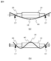
- FIG. 4 is a diagram showing the shapes of the primary bending vibration mode and the tertiary bending vibration mode of a two-pole rotor;
- 2 is a front cross-sectional view showing connection of rotor coils of a stepped portion of the rotor in FIG. 1;
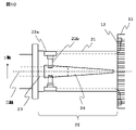
- FIG. 4 is a front perspective view showing a first example of a stepped portion of the rotor according to Embodiment 1;
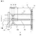
- FIG. 7 is a cross-sectional view taken along line BB of FIG. 6;
- FIG. 10 is a diagram showing an excitation force due to the asymmetry of the bending stiffness of a bipolar rotor;
- FIG. 8 is a front perspective view showing a second example of the rotor stepped portion in the first embodiment;
- FIG. 11 is a front perspective view showing a third example of the rotor stepped portion according to the first embodiment;
- FIG. 11 is a front perspective view showing a fourth example of the rotor stepped portion according to Embodiment 1;
- FIG. 7 is a sectional view taken along line BB in FIG.
- FIG. 7 is a diagram showing an example of division for calculating an equivalent bending rigidity asymmetry of the full length in the Z-axis direction of the stepped portion of the rotor in the first embodiment of FIG. 6 ;
- FIG. 7 is a sectional view taken along line BB in FIG. 6, showing an example of a stepped portion of the rotor according to Embodiment 2;
- FIG. 1 is an external side view showing the configuration of a two-pole rotor of a rotary electric machine according to Embodiment 1.
- FIG. FIG. 2 is a cross-sectional view showing the configuration of the rotor main portion when viewed from the direction of the arrows along the line AA in FIG.
- FIG. 3 is an external plan view of the dipole rotor in FIG. 1 as seen from the Y-axis direction.
- FIG. 4 is a diagram showing the shapes of the primary bending vibration mode and the tertiary bending vibration mode of the two-pole rotor.
- 5 is a front sectional view showing the connection of the rotor coils of the stepped portion of the rotor in FIG. 1.
- FIG. 6 is a front perspective view showing a first example of the rotor stepped portion according to Embodiment 1.
- FIG. 7 shows a cross-sectional view of the BB portion of FIG.
- FIG. 8 is a diagram showing the excitation force due to the asymmetry of the bending stiffness of the two-pole rotor.
- the configuration of the two-pole rotor 1 of the rotary electric machine according to Embodiment 1 will be described with reference to FIG.
- the two-pole rotor 1 shown in FIG. 1 has a rotor main portion 10 and a rotor stepped portion 20 provided on the side of the excitation device (the D direction in the drawing).
- the rotor main section 10 includes the rotor coil 13 wound around the rotor core 11, and the rotor core 11 with respect to its rotation axis (Z-axis).
- a plurality of rotor slots 12 are provided along the circumference and accommodate rotor coils 13, and rotor slots 12 are inserted into the outer diameter side of the rotor slots 12 to hold down the rotor coils 13. It is composed of a child wedge 14 and a plurality of cross slots 15 provided in the rotor core 11 at predetermined intervals (pitch) with respect to the direction of rotation of the bipolar rotor 1 and the direction of the axis of rotation.
- the operation of the dipole rotor 1 of Embodiment 1 will be described.
- the spacing of the cross slots 15 in the Z-axis direction as shown in FIG. 3 or the depth of cut of the cross slots 15 as shown in FIG. adjusting is the axis in the direction in which the rotor coils 13 of the rotor core 11 face each other.
- the axis orthogonal to it is the pole center axis (hereinafter referred to as the Y-axis). ).
- the rotor coils 13 in the rotor slots 12 are held by the rotor wedges 14, but when the bipolar rotor 1 rotates, the rotor coils 13 and the rotor wedges 14 are held. Due to the action of centrifugal force, they are constrained particularly in the axial direction between the poles and contribute to an increase in the bending stiffness around the center pole axis. That is, the bending rigidity about the X-axis of the rotor main portion 10 including the rotor core 11, the rotor coil 13, the rotor wedge 14, and the cross slot 15 is EIbrX, the bending rigidity about the Y-axis is EIbrY, and the rotor main portion 10 is EIbrY.
- EIbrY increases
- EIbr% of the rotor main portion 10 also increases. Therefore, it is necessary to determine the spacing of the cross slots 15 in the Z-axis direction or the depth of cut of the cross slots 15 in consideration of the rotation speed dependence of the asymmetry rate.
- E Young's modulus
- I is the geometrical moment of inertia
- b is the rotor main portion 10
- r is a subscript representing a ratio.
- the rated rotation speed of the two-pole rotor 1 such as a turbine generator is 3,000 rpm or 3,600 rpm, and a plurality of double frequency vibrations occur from a stopped state to the rated rotation speed. Pass the critical speed of bending vibration mode.
- FIG. 4 shows the shapes of the primary bending vibration mode and the tertiary bending vibration mode of the two-pole rotor. In both the primary bending vibration mode W1 (FIG. 4(a)) and the tertiary bending vibration mode W2 (FIG. 4(b)), the rotor main section 10 is at the antinode of the vibration mode with respect to the bearing 17.
- each bending vibration of the double-frequency vibration is Mode vibration must be suppressed.
- the two-pole rotor 1 of a rotary electric machine such as a turbine generator has a rotor stepped portion 20 having an asymmetric bending rigidity in addition to the rotor main portion 10, the rotor main portion 10 Only by optimizing the asymmetry of the bending stiffness, it may not be possible to sufficiently suppress the double frequency vibration in the entire operating speed range.
- FIG. 5 A side cross-sectional view of the rotor stepped portion 20 is shown in FIG.
- the rotor coil 13 passes through a rotor coil lead groove 21 provided over the rotation axis (Z-axis) direction at the outer diameter position of the rotor stepped portion 20 in the Y-axis direction, and rotates from the rotor coil lead groove 21 .
- the rotor coil lead portions are shown deformed from the actual ones in order to clarify the connection relationship with the rotor coil 13.
- the rotor stepped portion 20 is similar to the rotor main portion 10. It has asymmetry of bending stiffness. Further, as shown in FIG. 4, the rotor stepped portion 20 exists at the antinode 18 of the vibration mode with respect to the primary bending vibration mode W1 and the tertiary bending vibration mode W2. The asymmetry of the bending stiffness of the portion 20 also acts as a vibration source for the double frequency vibration.
- the asymmetry of the bending rigidity of the rotor main portion 10 also affects the bending rigidity of the rotor stepped portion 20 in the secondary bending vibration mode (not shown) that does not act as a vibration source.
- the rotor stepped portion 20 exists at the position of the antinode of the vibration mode, so it acts as a vibration source of the double frequency vibration.
- FIG. 6 is a front perspective view showing a first example of the rotor stepped portion according to Embodiment 1.
- FIG. 7 shows a cross-sectional view taken along the line BB in FIG.
- a set of cutout grooves 24 having the same cross-sectional shape are formed at the outer diameter position on the X-axis of the rotor stepped portion 20 so as to rotate substantially with respect to the Z-axis direction. It is provided over the entire length of the stepped portion 20 .
- the rotor stepped portion 20 is provided with the rotor coil lead groove 21 and the radial lead grooves 22a and 22b. descend.
- EIsrX is the bending rigidity of the rotor stepped portion 20 about the X axis
- EIsrY is the bending rigidity about the Y axis
- EIsrX is smaller than EIsrY, so the asymmetry ratio EIsr% does not become 0%. It means that it has asymmetry with respect to bending stiffness.
- E is Young's modulus
- I is the geometrical moment of inertia
- s is the stepped portion 20 of the rotor
- r is a subscript representing a ratio.
- the optimum bending rigidity asymmetry ratio EIbr% of the rotor main portion 10 and the rotor stepped portion 20 are A combination of the bending rigidity asymmetry ratio EIsr% will be described with reference to FIG.
- FIG. 8 shows the excitation force of the primary bending vibration mode W1 of the double frequency vibration caused by the asymmetry rate EIbr% of the rotor main portion 10 and the asymmetry rate EIsr% of the rotor stepped portion 20 (FIG. 8(a ), (b)) and the excitation force of the tertiary bending vibration mode W2 (FIGS. 8(c), (d)).
- the rotor stepped portion 20 has EIsr%>0% because the rotor coil lead groove 21 and the radial lead grooves 22a and 22b reduce the bending rigidity around the X axis.
- the rotor stepped section 20 does not change the excitation force over the entire range of the operating speed.
- the asymmetry rate EIsr% of does not change over the entire operating speed range.
- the asymmetry ratio EIbr% of the bending rigidity of the rotor main section 10 should be such that EIbr% ⁇ when the primary bending vibration mode W1 resonates. 0%, and adjustment may be made so that EIbr%>0% at the time of resonance in the tertiary bending vibration mode W2.
- EIbr% ⁇ 0% and EIsr%>0%, 3 EIbr%>0% and EIsr%>0% should be satisfied at the resonance of the next bending vibration mode W2, but the asymmetry ratios EIbr% and EIsr% have an optimum applicable range.
- Formula 1 shows the optimum range during resonance of the primary bending vibration mode W1 of double frequency vibration
- Formula 2 shows the optimum range during resonance of the tertiary bending vibration mode W2.
- Equation (2) As for the secondary bending vibration mode of the double frequency vibration, it is possible to sufficiently suppress the double frequency vibration by applying Equation (2).
- the notch groove 24 is a groove provided at the outer diameter position on the X-axis of the rotor stepped portion 20, and means a groove that has no role other than suppressing the double frequency vibration of the rotor. Note that the shape of the notch groove 24 is not limited to the shapes shown in FIGS. 6 and 7, as described below.
- FIGS. 9 to 12 show other examples of the shape of the notch groove 24 of the rotor stepped portion 20 of the bipolar rotor 1 according to the first embodiment.
- FIG. 9 shows a second embodiment of the notch groove.
- the pair of cutout grooves 24 of the rotor stepped portion 20 have the same cross-sectional shape in the Z-axis direction, whereas in the second embodiment
- a notch groove 24 is provided in the Z-axis direction, which is composed of two notch grooves 24a and 24b having different cross-sectional shapes and lengths.
- FIG. 10 shows a third embodiment of notch grooves.
- a set of notch grooves 24 of the rotor stepped portion 20 has a tapered cross-sectional shape with respect to the Z-axis direction. Note that the length of the notch groove 24 in the Z-axis direction is not limited. may be provided.
- FIG. 11 shows a fourth embodiment.
- a plurality of notch grooves 24a and 24b are provided at different positions of the notch groove 24 with respect to the Z-axis direction.
- the notch groove 24 having a symmetrical shape with respect to the Y-axis is provided with the effect of suppressing the double frequency vibration.
- the notched groove 24 may be provided only on one side with respect to the Y axis.
- the attached portion 20 has a different cross-sectional shape in the Z-axis direction.
- the asymmetry ratio EIsr% defined in the present embodiment does not indicate the asymmetry ratio of one cross section where the rotor stepped portion 20 is present, but the equivalent bending rigidity of the rotor stepped portion 20 over the entire length in the axial direction. Refers to the asymmetry rate.
- FIG. 13 is a diagram showing an example of division for calculating the equivalent bending rigidity asymmetry over the entire length in the Z-axis direction of the stepped portion of the rotor in the first embodiment shown in FIG.
- the bending rigidity asymmetry ratio EIsr% of the rotor stepped portion 20 in FIG. 6 can be calculated by dividing n as shown in FIG. EIsr% can be expressed by Equation 3 below.
- EIsrn (EIsrYn/EIsrXn ⁇ 1) ⁇ 100, which indicates the asymmetry rate of the bending rigidity of each portion of length Ln in the Z-axis direction.
- the asymmetry of the bending rigidity of the rotor main portion is adjusted by the cross slots provided in the rotor core, and the stepped portion of the rotor is adjusted.
- the asymmetry of the bending rigidity of the stepped portion of the rotor with the notch groove provided in the rotor the asymmetry of the bending rigidity of the rotor main portion and the bending rigidity of the stepped portion of the rotor are combined. Therefore, it is possible to reduce the excitation force existing at the antinode position of the vibration mode for each bending vibration mode of the double frequency vibration. There is an effect that the vibration of each bending vibration mode of the double frequency vibration can be suppressed over the region.
- FIG. 14 shows the rotor stepped portion 20 on the side of the excitation device of the two-pole rotor 1 of the rotary electric machine according to Embodiment 2.
- FIG. A cross-sectional view is shown. The difference from the first embodiment is that, in the second embodiment, four notch grooves 24 are formed in the outer diameter position of the rotor stepped portion 20 within an angle range of 0 to 45 degrees in the Y-axis direction centering on the X-axis. It is a point that is provided in places. Note that the description of the configuration similar to that of the first embodiment is omitted.
- the notched grooves 24 are not limited to being provided at four locations in the circumferential direction.
- the shape of the cutout groove 24 is not limited to the shape shown in FIG. 14, and the cross-sectional shape may be changed in a plurality of stages in the Z-axis direction, and the cross-sectional shape in the Z-axis direction is tapered. may be changed to have Furthermore, there is no restriction on the length of the notch groove 24 in the Z-axis direction. Alternatively, it may be partially provided in the Z-axis direction. Furthermore, the notch grooves 24 may be provided at a plurality of locations in the Z-axis direction.
- the cutout groove is provided in the stepped portion on the side of the excitation device in order to suppress the double frequency vibration of the two-pole rotor of the rotary electric machine.
- a notch groove may be provided in the portion. It is also applicable to rotors of other rotating electric machines.
- the notch groove has a shape extending in the rotation axis direction, but it may have a shape extending in the circumferential direction.
Abstract
Description
2極回転子の回転子スロットは、回転子鉄心の円周方向360度に対して等配置にはなっておらず、極間軸側に集中して配置される。即ち、これは、回転子鉄心が、極間軸まわりの曲げ剛性及び極中軸まわりの曲げ剛性に非対称性を有することを意味する。この非対称性により、回転数に対して2倍の周波数を有する重力たわみの変化(2倍周波数振動)が発生する。 2. Description of the Related Art In a two-pole rotor of a rotary electric machine such as a turbine generator, a plurality of rotor slots are provided in a rotor core in a circumferential direction around a rotation axis. Coil is included. A rotor wedge for holding the rotor coil is inserted in the outer diameter side of the rotor slot.
The rotor slots of the two-pole rotor are not evenly arranged in the circumferential direction of 360 degrees of the rotor core, but are concentrated on the inter-polar shaft side. That is, this means that the rotor core has asymmetry in bending stiffness about the inter-pole axis and bending stiffness about the center pole axis. This asymmetry produces changes in gravitational deflection that have twice the frequency with respect to rotational speed (double frequency oscillation).
図1は、実施の形態1に係る回転電機の2極回転子の構成を示す外観側面図である。図2は、図1のA-A部を矢印方向から見た回転子主部の構成を示す断面図である。図3は、図1における2極回転子をY軸方向から見た外観平面図である。図4は、2極回転子の1次曲げ振動モード及び3次曲げ振動モードの形状を示す図である。図5は、図1における回転子段付部の回転子コイルの接続を示す正面断面図である。図6は、実施の形態1における回転子段付部の第1の実施例を示す正面透視図である。図7は、図6のB-B部の断面図を示す。また、図8は、2極回転子の曲げ剛性の非対称性による加振力を示す図である。
FIG. 1 is an external side view showing the configuration of a two-pole rotor of a rotary electric machine according to
図3に示すように、クロススロット15のZ軸方向の間隔、あるいは図2に示すように、クロススロット15の切り込みの深さを調整することで、回転子鉄心11の曲げ剛性の非対称性を調整している。ここで、図2において、回転子鉄心11の回転子コイル13同士が対向する方向の軸を極間軸(以下、X軸と称する。)、それに直交する軸を極中軸(以下、Y軸と称する。)と定義する。 Next, the operation of the
By adjusting the spacing of the
なお、Eはヤング率、Iは断面二次モーメント、bは回転子主部10、rは比率を表す添字である。 As shown in FIG. 2, the rotor coils 13 in the
Here, E is Young's modulus, I is the geometrical moment of inertia, b is the rotor
なお、Eはヤング率、Iは断面二次モーメント、sは回転子段付部20、rは比率を表す添字である。 FIG. 6 is a front perspective view showing a first example of the rotor stepped portion according to
Here, E is Young's modulus, I is the geometrical moment of inertia, s is the stepped


図14は、実施の形態2に係る回転電機の2極回転子1の励磁装置側の回転子段付部20を示すものであり、図6の回転子段付部20のB-B部における断面図を示す。実施の形態1との相違点は、実施の形態2では、X軸を中心としてY軸方向に0から45度の角度範囲で回転子段付部20の外径位置に切り欠き溝24が4ヶ所設けられている点である。なお、実施の形態1と同様の構成については、説明を省略する。 Embodiment 2.
FIG. 14 shows the rotor stepped
従って、例示されていない無数の変形例が、本願明細書に開示される技術の範囲内において想定される。例えば、少なくとも1つの構成要素を変形する場合、追加する場合または省略する場合、さらには、少なくとも1つの構成要素を抽出し、他の実施の形態の構成要素と組み合わせる場合が含まれるものとする。 Also, while this application has described various exemplary embodiments and example implementations, the various features, aspects, and functions described in one or more embodiments may be construed in particular implementations. The embodiments are not limited to the application of the forms, but can be applied to the embodiments singly or in various combinations.
Accordingly, numerous variations not illustrated are envisioned within the scope of the technology disclosed herein. For example, modification, addition or omission of at least one component, extraction of at least one component, and combination with components of other embodiments shall be included.
Claims (11)
- 回転子段付部に、極中軸まわりの曲げ剛性を調整し、かつ極間軸まわりの曲げ剛性と前記極中軸まわりの曲げ剛性とが非対称性を有するように切り欠き溝が、前記回転子段付部の回転軸方向に少なくとも一つ設けられていることを特徴とする回転電機の回転子。 The rotor stepped portion is provided with notched grooves for adjusting the bending rigidity about the pole center axis and providing asymmetry between the bending rigidity about the inter-pole axis and the bending rigidity about the pole center axis. A rotor for a rotary electric machine, wherein at least one rotor is provided in the rotation axis direction of the attached portion.
- 前記回転子段付部の前記極間軸上の外径位置に、断面形状が同一の複数の前記切り欠き溝が、前記回転軸方向に対して前記回転子段付部の一部あるいは全長に亘り、少なくとも一組設けられていることを特徴とする請求項1に記載の回転電機の回転子。 A plurality of notch grooves having the same cross-sectional shape are formed at the outer diameter position of the rotor stepped portion on the interpolar axis, along a part or the entire length of the rotor stepped portion with respect to the rotation axis direction. 2. The rotor for a rotary electric machine according to claim 1, wherein at least one set of rotors is provided over the entire length of the rotor.
- 前記回転子段付部の前記極間軸上の外径位置に、断面形状が異なる複数の前記切り欠き溝が、前記回転軸方向に対して前記回転子段付部の一部あるいは全長に亘り、少なくとも一組設けられていることを特徴とする請求項1に記載の回転電機の回転子。 A plurality of notch grooves having different cross-sectional shapes are formed at the outer diameter position of the rotor stepped portion on the interpolar axis, extending over part or the entire length of the rotor stepped portion with respect to the rotation axis direction. , at least one set of rotors for a rotary electric machine according to claim 1.
- 前記回転子段付部の前記極間軸上の外径位置に、断面形状がテーパ形状を有する前記切り欠き溝が、前記回転軸方向に対して前記回転子段付部の一部あるいは全長に亘り、少なくとも一つ設けられていることを特徴とする請求項1に記載の回転電機の回転子。 The notch groove having a tapered cross-sectional shape is provided at the outer diameter position of the rotor stepped portion on the interpolar axis, along a part or the entire length of the rotor stepped portion with respect to the rotation axis direction. 2. The rotor of a rotary electric machine according to claim 1, wherein at least one rotor is provided along the length of the rotor.
- 前記極間軸を中心とした前記極中軸方向に0から45度の角度範囲で、前記回転子段付部の外径位置に、断面形状が同一の複数の前記切り欠き溝が、前記回転軸方向に対して前記回転子段付部の一部あるいは全長に亘り、少なくとも一組設けられていることを特徴とする請求項1に記載の回転電機の回転子。 A plurality of notch grooves having the same cross-sectional shape are formed on the outer diameter position of the rotor stepped portion within an angle range of 0 to 45 degrees in the pole center axis direction about the inter-pole axis. 2. A rotor for a rotary electric machine according to claim 1, wherein at least one pair of said rotor stepped portions is provided along a part or over the entire length of said rotor stepped portion.
- 前記極間軸を中心とした前記極中軸方向に0から45度の角度範囲で、前記回転子段付部の外径位置に、断面形状が異なる複数の前記切り欠き溝が、前記回転軸方向に対して前記回転子段付部の一部あるいは全長に亘り、少なくとも一組設けられていることを特徴とする請求項1に記載の回転電機の回転子。 A plurality of cutout grooves having different cross-sectional shapes are formed at outer diameter positions of the rotor stepped portion within an angle range of 0 to 45 degrees in the pole center axial direction centered on the interpolar axis. 2. The rotor for a rotary electric machine according to claim 1, wherein at least one set of the stepped portions of the rotor is provided over a portion or the entire length of the stepped portion of the rotor.
- 前記極間軸を中心とした前記極中軸方向に0から45度の角度範囲で、前記回転子段付部の外径位置に、断面形状がテーパ形状を有する複数の前記切り欠き溝が、前記回転軸方向に対して前記回転子段付部の一部あるいは全長に亘り、少なくとも一組設けられていることを特徴とする請求項1に記載の回転電機の回転子。 A plurality of cutout grooves having a tapered cross-sectional shape are provided at outer diameter positions of the rotor stepped portion within an angle range of 0 to 45 degrees in the pole center axis direction about the inter-pole axis. 2. The rotor of a rotary electric machine according to claim 1, wherein at least one set of the stepped portion of the rotor is provided along the direction of the rotating shaft or over the entire length of the stepped portion of the rotor.
- 前記回転子段付部の極中軸まわりの曲げ剛性を前記切り欠き溝によって調整することで、運転回転数の全領域における2倍周波数振動を抑制することを特徴とする請求項2から7のいずれか1項に記載の回転電機の回転子。 8. The double frequency vibration in the entire operating speed range is suppressed by adjusting the flexural rigidity of the stepped portion of the rotor about the pole center axis by means of the cutout groove. 1. A rotor of a rotary electric machine according to claim 1.
- 回転子主部の前記極間軸まわりの曲げ剛性に対する前記極中軸まわりの曲げ剛性の非対称率が、2倍周波数振動の1次曲げ振動モードの共振時に-6から-1%かつ3次曲げ振動モードの共振時に1から6%を有し、前記回転子段付部の前記極間軸まわりの曲げ剛性に対する前記極中軸まわりの曲げ剛性の非対称率が1から6%を有することを特徴とする請求項8に記載の回転電機の回転子。 The asymmetry ratio of the bending stiffness about the center pole axis with respect to the bending stiffness about the inter-pole axis of the rotor main part is -6 to -1% at the resonance of the first bending vibration mode of the double frequency vibration and the third bending vibration. 1 to 6% at mode resonance, and an asymmetry ratio of the bending stiffness about the center pole axis to the bending stiffness about the inter-pole axis of the rotor stepped portion is 1 to 6%. A rotor for a rotary electric machine according to claim 8 .
- 前記回転子段付部の前記極間軸まわりの曲げ剛性に対する前記極中軸まわりの曲げ剛性の非対称率が1から6%を有することで、2倍周波数振動の2次曲げ振動モードの振動を抑制することを特徴とする請求項9に記載の回転電機の回転子。 The asymmetry ratio of the bending rigidity about the center pole axis with respect to the bending rigidity about the inter-pole axis of the rotor stepped portion is 1 to 6%, thereby suppressing the vibration of the secondary bending vibration mode of the double frequency vibration. The rotor of a rotary electric machine according to claim 9, characterized in that:
- 請求項1から10のいずれか1項に記載の前記回転子を備えたことを特徴とする回転電機。 A rotating electrical machine comprising the rotor according to any one of claims 1 to 10.
Priority Applications (5)
| Application Number | Priority Date | Filing Date | Title |
|---|---|---|---|
| CN202180091933.4A CN116746034A (en) | 2021-02-01 | 2021-02-01 | Rotor of rotating electrical machine and rotating electrical machine |
| PCT/JP2021/003479 WO2022162930A1 (en) | 2021-02-01 | 2021-02-01 | Rotor of rotating electrical machine and rotating electrical machine |
| US18/251,642 US20230421005A1 (en) | 2021-02-01 | 2021-02-01 | Rotor of rotating electric machine and rotating electric machine |
| DE112021007001.0T DE112021007001T5 (en) | 2021-02-01 | 2021-02-01 | ROTOR OF A ROTATING ELECTRICAL MACHINE AND ROTATING ELECTRIC MACHINE |
| JP2022577997A JP7387035B2 (en) | 2021-02-01 | 2021-02-01 | Rotor of rotating electrical machine and rotating electrical machine |
Applications Claiming Priority (1)
| Application Number | Priority Date | Filing Date | Title |
|---|---|---|---|
| PCT/JP2021/003479 WO2022162930A1 (en) | 2021-02-01 | 2021-02-01 | Rotor of rotating electrical machine and rotating electrical machine |
Publications (1)
| Publication Number | Publication Date |
|---|---|
| WO2022162930A1 true WO2022162930A1 (en) | 2022-08-04 |
Family
ID=82653243
Family Applications (1)
| Application Number | Title | Priority Date | Filing Date |
|---|---|---|---|
| PCT/JP2021/003479 WO2022162930A1 (en) | 2021-02-01 | 2021-02-01 | Rotor of rotating electrical machine and rotating electrical machine |
Country Status (5)
| Country | Link |
|---|---|
| US (1) | US20230421005A1 (en) |
| JP (1) | JP7387035B2 (en) |
| CN (1) | CN116746034A (en) |
| DE (1) | DE112021007001T5 (en) |
| WO (1) | WO2022162930A1 (en) |
Citations (4)
| Publication number | Priority date | Publication date | Assignee | Title |
|---|---|---|---|---|
| JPS54125407A (en) * | 1978-03-22 | 1979-09-28 | Toshiba Corp | Rotor of rotary machine |
| JPS54136603A (en) * | 1978-04-17 | 1979-10-23 | Toshiba Corp | Rotor for rotating electric machine |
| JPS56174934U (en) * | 1980-05-26 | 1981-12-24 | ||
| JP2005160141A (en) * | 2003-11-20 | 2005-06-16 | Toshiba Corp | Rotor for dynamo-electric machine |
-
2021
- 2021-02-01 DE DE112021007001.0T patent/DE112021007001T5/en active Pending
- 2021-02-01 US US18/251,642 patent/US20230421005A1/en active Pending
- 2021-02-01 WO PCT/JP2021/003479 patent/WO2022162930A1/en active Application Filing
- 2021-02-01 JP JP2022577997A patent/JP7387035B2/en active Active
- 2021-02-01 CN CN202180091933.4A patent/CN116746034A/en active Pending
Patent Citations (4)
| Publication number | Priority date | Publication date | Assignee | Title |
|---|---|---|---|---|
| JPS54125407A (en) * | 1978-03-22 | 1979-09-28 | Toshiba Corp | Rotor of rotary machine |
| JPS54136603A (en) * | 1978-04-17 | 1979-10-23 | Toshiba Corp | Rotor for rotating electric machine |
| JPS56174934U (en) * | 1980-05-26 | 1981-12-24 | ||
| JP2005160141A (en) * | 2003-11-20 | 2005-06-16 | Toshiba Corp | Rotor for dynamo-electric machine |
Also Published As
| Publication number | Publication date |
|---|---|
| JP7387035B2 (en) | 2023-11-27 |
| JPWO2022162930A1 (en) | 2022-08-04 |
| US20230421005A1 (en) | 2023-12-28 |
| CN116746034A (en) | 2023-09-12 |
| DE112021007001T5 (en) | 2023-11-30 |
Similar Documents
| Publication | Publication Date | Title |
|---|---|---|
| US20190348879A1 (en) | Rotor for rotating electric machine | |
| CN111130234B (en) | Electric machine with hybrid tooth design | |
| US20120112600A1 (en) | Stator for electric rotating machine | |
| JP6191370B2 (en) | Synchronous motor | |
| JP5511921B2 (en) | Electric motor, blower and compressor | |
| CN111937276A (en) | Coil formation in an electric machine with concentrated windings | |
| RU2654211C2 (en) | Electric machine rotor | |
| JP6987310B1 (en) | Rotating machine | |
| WO2022162930A1 (en) | Rotor of rotating electrical machine and rotating electrical machine | |
| JP6738395B2 (en) | Rotor | |
| JP2009106001A (en) | Rotary electric machine | |
| KR101054155B1 (en) | Rotor and damper windings for rotor in generator | |
| EP4220899A1 (en) | Rotor core | |
| JP2020114129A (en) | Rotor core of rotary electric machine | |
| JP2010148294A (en) | Rotor of electric motor | |
| JP2015220846A (en) | Rotor of dynamo-electric machine | |
| JP6420488B2 (en) | Permanent magnet type rotary electric motor and compressor using the same | |
| WO2018070430A1 (en) | Synchronous reluctance rotary electric machine | |
| JPH0556100B2 (en) | ||
| US11329535B2 (en) | Manufacturing method for a segmented stator or rotor of an electrical machine | |
| JP2015002565A (en) | Dynamo-electric machine | |
| JP2005160141A (en) | Rotor for dynamo-electric machine | |
| JP2021005990A (en) | Induction motor | |
| JP6641520B2 (en) | Rotary electric machine control device, rotary electric machine, and control method for rotary electric machine | |
| CN108233570B (en) | Rotor and permanent magnet type rotating electric machine |
Legal Events
| Date | Code | Title | Description |
|---|---|---|---|
| 121 | Ep: the epo has been informed by wipo that ep was designated in this application |
Ref document number: 21922942 Country of ref document: EP Kind code of ref document: A1 |
|
| ENP | Entry into the national phase |
Ref document number: 2022577997 Country of ref document: JP Kind code of ref document: A |
|
| WWE | Wipo information: entry into national phase |
Ref document number: 202180091933.4 Country of ref document: CN |
|
| WWE | Wipo information: entry into national phase |
Ref document number: 112021007001 Country of ref document: DE |
|
| 122 | Ep: pct application non-entry in european phase |
Ref document number: 21922942 Country of ref document: EP Kind code of ref document: A1 |