CN111130234B - Electric machine with hybrid tooth design - Google Patents
Electric machine with hybrid tooth design Download PDFInfo
- Publication number
- CN111130234B CN111130234B CN201911044674.0A CN201911044674A CN111130234B CN 111130234 B CN111130234 B CN 111130234B CN 201911044674 A CN201911044674 A CN 201911044674A CN 111130234 B CN111130234 B CN 111130234B
- Authority
- CN
- China
- Prior art keywords
- teeth
- stator
- circumferentially
- rotor
- slots
- Prior art date
- Legal status (The legal status is an assumption and is not a legal conclusion. Google has not performed a legal analysis and makes no representation as to the accuracy of the status listed.)
- Active
Links
Images


Classifications
-
- H—ELECTRICITY
- H02—GENERATION; CONVERSION OR DISTRIBUTION OF ELECTRIC POWER
- H02K—DYNAMO-ELECTRIC MACHINES
- H02K1/00—Details of the magnetic circuit
- H02K1/06—Details of the magnetic circuit characterised by the shape, form or construction
- H02K1/12—Stationary parts of the magnetic circuit
- H02K1/16—Stator cores with slots for windings
- H02K1/165—Shape, form or location of the slots
-
- H—ELECTRICITY
- H02—GENERATION; CONVERSION OR DISTRIBUTION OF ELECTRIC POWER
- H02K—DYNAMO-ELECTRIC MACHINES
- H02K1/00—Details of the magnetic circuit
- H02K1/06—Details of the magnetic circuit characterised by the shape, form or construction
- H02K1/12—Stationary parts of the magnetic circuit
- H02K1/18—Means for mounting or fastening magnetic stationary parts on to, or to, the stator structures
- H02K1/187—Means for mounting or fastening magnetic stationary parts on to, or to, the stator structures to inner stators
-
- H—ELECTRICITY
- H02—GENERATION; CONVERSION OR DISTRIBUTION OF ELECTRIC POWER
- H02K—DYNAMO-ELECTRIC MACHINES
- H02K1/00—Details of the magnetic circuit
- H02K1/06—Details of the magnetic circuit characterised by the shape, form or construction
- H02K1/22—Rotating parts of the magnetic circuit
- H02K1/26—Rotor cores with slots for windings
- H02K1/265—Shape, form or location of the slots
-
- H—ELECTRICITY
- H02—GENERATION; CONVERSION OR DISTRIBUTION OF ELECTRIC POWER
- H02K—DYNAMO-ELECTRIC MACHINES
- H02K3/00—Details of windings
- H02K3/04—Windings characterised by the conductor shape, form or construction, e.g. with bar conductors
- H02K3/28—Layout of windings or of connections between windings
-
- H—ELECTRICITY
- H02—GENERATION; CONVERSION OR DISTRIBUTION OF ELECTRIC POWER
- H02K—DYNAMO-ELECTRIC MACHINES
- H02K1/00—Details of the magnetic circuit
- H02K1/06—Details of the magnetic circuit characterised by the shape, form or construction
- H02K1/12—Stationary parts of the magnetic circuit
- H02K1/14—Stator cores with salient poles
- H02K1/146—Stator cores with salient poles consisting of a generally annular yoke with salient poles
- H02K1/148—Sectional cores
-
- H—ELECTRICITY
- H02—GENERATION; CONVERSION OR DISTRIBUTION OF ELECTRIC POWER
- H02K—DYNAMO-ELECTRIC MACHINES
- H02K2213/00—Specific aspects, not otherwise provided for and not covered by codes H02K2201/00 - H02K2211/00
- H02K2213/12—Machines characterised by the modularity of some components
-
- H—ELECTRICITY
- H02—GENERATION; CONVERSION OR DISTRIBUTION OF ELECTRIC POWER
- H02K—DYNAMO-ELECTRIC MACHINES
- H02K7/00—Arrangements for handling mechanical energy structurally associated with dynamo-electric machines, e.g. structural association with mechanical driving motors or auxiliary dynamo-electric machines
- H02K7/18—Structural association of electric generators with mechanical driving motors, e.g. with turbines
- H02K7/1807—Rotary generators
- H02K7/1823—Rotary generators structurally associated with turbines or similar engines
- H02K7/183—Rotary generators structurally associated with turbines or similar engines wherein the turbine is a wind turbine
-
- Y—GENERAL TAGGING OF NEW TECHNOLOGICAL DEVELOPMENTS; GENERAL TAGGING OF CROSS-SECTIONAL TECHNOLOGIES SPANNING OVER SEVERAL SECTIONS OF THE IPC; TECHNICAL SUBJECTS COVERED BY FORMER USPC CROSS-REFERENCE ART COLLECTIONS [XRACs] AND DIGESTS
- Y02—TECHNOLOGIES OR APPLICATIONS FOR MITIGATION OR ADAPTATION AGAINST CLIMATE CHANGE
- Y02E—REDUCTION OF GREENHOUSE GAS [GHG] EMISSIONS, RELATED TO ENERGY GENERATION, TRANSMISSION OR DISTRIBUTION
- Y02E10/00—Energy generation through renewable energy sources
- Y02E10/70—Wind energy
- Y02E10/72—Wind turbines with rotation axis in wind direction
Abstract
A stator segment (100) for a stator (11) or a rotor (12) of an electrical machine (10) is described, comprising a segment body (22) extending circumferentially around a longitudinal axis (Y) of the stator segment (100) between two circumferential ends (23). The segment body (22) includes: a plurality of teeth (15, 16) projecting according to a radial direction orthogonal to the longitudinal axis (Y), each tooth (15, 16) extending circumferentially between two respective lateral faces (25, 26), the plurality of teeth (15, 16) being distributed circumferentially between two end teeth (15) of the plurality of teeth (15, 16), the plurality of teeth (15, 16) comprising at least one intermediate tooth (16) circumferentially comprised between the end teeth (15); a plurality of grooves (17, 18), the plurality of grooves (17, 18) comprising a plurality of intermediate grooves (18) circumferentially comprised between the two end grooves (17), wherein the side faces (25) of the two end teeth (15) are inclined with respect to each other or parallel to each other and the side face (26) of at least one intermediate tooth (16) is parallel to each other or inclined with respect to each other, respectively.
Description
Technical Field
The present invention relates to an electric machine having a stator or rotor with a segmented geometry (i.e., a stator or rotor comprising a plurality of stator segments circumferentially joined together).
Background
In large electrical machines, segmentation of the stator and/or rotor structure is required for ease of manufacture and transportation. This is particularly required for stators or rotors in which the windings are arranged. Due to manufacturing tolerances and limitations, it is common to design a tolerance circumferential gap between the segments.
The segment circumferential gap often leads to problems with undesired harmonics of the torque and output power of the electrical machine, which may lead to high levels of vibration and acoustic noise as well as losses and complex control. Therefore, to minimize the adverse impact on performance, it is important to control the shape and size of the circumferential gap.
For motors having half-teeth at the circumferential ends of the segments (typically, integer slot motors with distributed windings), the shape and size of the segment circumferential gap can be controlled by conveniently shaping and sizing the half-teeth. This has no adverse effect on the area of the slots for accommodating the copper windings and, therefore, the torque and output power of the motor are not affected.
For electrical machines in which half slots are present at each circumferential end of a segment (typically, fractional slot machines with concentrated windings), it is not possible to modify the slots, for example by reducing their width, as this would reduce the area of the windings. A reduction in the winding area will increase the resistance in this particular coil and thus increase the losses. By having an unbalanced loss between the coils, it would be expected to create hot spots in the circumferential end coils, thus limiting the operating point of the entire machine from a thermal perspective.
Disclosure of Invention
It is the scope of the present invention to provide a new segment design for controlling the shape and size of the circumferential gap in a segmented stator or rotor having half-slots at the circumferential ends of the segments in order to minimize the above-mentioned adverse effects.
This scope is met by the subject matter according to the independent claims. Advantageous embodiments of the invention are described by the dependent claims.
According to the invention, a segment for a stator or rotor of an electrical machine is provided, comprising a segment body extending circumferentially around a longitudinal axis of the stator segment between two circumferential ends. The segment body includes:
a plurality of teeth projecting according to a radial direction orthogonal to the longitudinal axis, each tooth extending circumferentially between two respective lateral faces, the plurality of teeth being distributed circumferentially between two end teeth of the plurality of teeth, the plurality of teeth comprising at least one intermediate tooth circumferentially comprised between the end teeth,
a plurality of slots circumferentially interposed between the teeth of the stator, said plurality of slots being circumferentially distributed between two end slots, each end slot being circumferentially comprised between a respective end tooth and a respective circumferential end, said plurality of slots comprising a plurality of intermediate slots circumferentially comprised between said two end slots,
wherein the side faces of the two end teeth are inclined or parallel to each other and the side faces of the at least one intermediate tooth are parallel or inclined to each other, respectively.
The above-described segments can advantageously be integrated in a segmented stator or rotor of an electrical machine (generator or electric motor). For example, the above-described segment may advantageously be integrated in a stator of a generator for a wind turbine.
According to the present invention, the mixing of tooth designs combines the advantages of both designs in order to reduce torque and power harmonics caused by the addition of the required segment tolerance circumferential gap, without modifying the presence of half slots at each circumferential end of the segment.
According to one embodiment of the invention, the side faces of the two end teeth are inclined with respect to each other and the side faces of the at least one intermediate tooth are parallel to each other. In particular, the side faces of the two end teeth may be oriented radially with respect to the longitudinal axis.
In the circumferentially intermediate region of the segment, the intermediate teeth with side faces parallel to each other (parallel tooth geometry) define slots with a lower copper fill factor. This allows providing a reduction in the end winding length by using an easier coil insertion procedure, i.e. the coil does not have to be deformed in order to get over a wider tooth crest, as is the case with the parallel slot configuration.
Alternatively, a parallel slot design geometry is provided at the circumferential ends, which provides a good slot fill factor, which is particularly advantageous for machines with large conductor sizes. The use of parallel slots further allows torque ripple reduction to be achieved.
According to another possible embodiment of the invention, the side faces of the two end teeth are parallel to each other and the side faces of the at least one intermediate tooth are inclined with respect to each other. In particular, the side faces of the at least one intermediate tooth may be oriented radially with respect to the longitudinal axis.
Also, in this embodiment, the mixing of the tooth design combines the advantages of both designs in order to reduce torque and power harmonics caused by the addition of the required segment tolerance gap, as explained in detail above with reference to the previously described embodiments.
According to an embodiment of the invention, the segment comprises a coil winding arranged in a segment body, the coil winding comprising at least two side coils respectively received in end slots. The coil winding may be a double layer winding including two coils in each of the intermediate slots. In particular, the coil winding may be a coil concentrated winding or a double-layer coil distributed winding.
The aspects defined above and further aspects of the invention are apparent from the examples of embodiment to be described hereinafter and are explained with reference to these examples of embodiment. The invention will be described in more detail hereinafter with reference to examples of embodiment but to which the invention is not limited.
Drawings
Fig. 1 shows a schematic cross section of a wind turbine comprising a generator with a stator geometry according to the present invention.
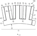
Fig. 2 shows a partial cross section of a generator according to the invention.
Fig. 3 shows a partial cross-section of a first embodiment of the generator of fig. 2.
Fig. 4 shows a partial cross-section of a second embodiment of the generator of fig. 2.
Detailed Description
The illustration in the drawings is schematically. It should be noted that in different figures, similar or identical elements are provided with the same reference numerals.
Fig. 1 shows a wind turbine 1 according to the invention. The wind turbine 1 comprises a tower 2, which tower 2 is mounted on a foundation, not depicted. The nacelle 3 is arranged on top of the tower 2.
The wind turbine 1 further comprises a wind rotor 5 with two, three or more blades 4 (in the perspective view of fig. 1 only two blades 4 are visible). The wind rotor 5 is rotatable about an axis of rotation Y. When not specifically specified, the terms axial, radial and circumferential are made with reference to the axis of rotation Y in the following.
The blades 4 extend radially with respect to the rotation axis Y.
The wind turbine 1 comprises a concentrated winding generator 10.
The wind rotor 5 is rotationally coupled with a generator 10 by means of a rotatable main shaft 9.
According to other possible embodiments of the invention (not shown in the drawings), the wind rotor 5 is directly rotationally coupled with the generator 10 (direct drive generator configuration).
In order to hold the rotor 5 in place, a schematically depicted bearing assembly 8 is provided. The rotatable spindle 9 extends along the axis of rotation Y. The permanent magnet generator 10 includes a stator 11 and a rotor 12. The rotor 12 is radially external to the stator 11 and is rotatable relative to the stator 11 about a rotation axis Y. According to other embodiments of the invention (not shown), the rotor is radially inside the stator 11.
According to other possible embodiments of the invention (not shown in the figures), the invention can be applied to any generator or electric motor with a concentrated winding topology, for example a gear train or an electric machine of synchronous or asynchronous type.
According to other possible embodiments of the invention (not shown in the drawings), the invention can be applied to any generator or electric motor with double-layer distributed winding of coils.
Fig. 2 shows a partial schematic view of a cross section orthogonal to the axis of rotation Y of a generator 10 with a radially inner stator 11 and a radially outer rotor 12. The generator 10 comprises a circumferential air gap 19 interposed radially between the stator 11 and the rotor 12. The rotor 12 comprises a plurality of circumferentially distributed permanent magnets 31. A circumferential air gap 19 is radially interposed between the permanent magnet 31 and the stator 11.
The stator 11 comprises a plurality of circumferential segments 100, the circumferential segments 100 being circumferentially joined together as follows: a circumferential gap 110 is interposed between two circumferentially adjacent stator segments 100. The stator 11 has a tooth-like structure as described below for accommodating the coil windings 30 arranged in each of the stator segments 100.
According to other possible embodiments of the invention (not shown in the drawings), the invention and the following description apply to the rotor of an electric machine.
Referring to fig. 3 and 4, each segment 100 includes a segment body 22 extending circumferentially about the longitudinal axis Y between two circumferential ends 23. The segment body 22 includes a yoke 13, a plurality of teeth 15, 16, and a plurality of grooves 17, 18.
Each tooth 15, 16 projects from the yoke 13 according to a radial direction orthogonal to the longitudinal axis Y. The plurality of teeth 15, 16 are circumferentially distributed between two end teeth 15 of the plurality of teeth 15, 16. Each end tooth 15 extends circumferentially between two respective side faces 25. The plurality of teeth 15, 16 comprises at least one intermediate tooth 16 (two intermediate teeth 16 are shown in fig. 3 and 4) circumferentially comprised between the end teeth 15. Each intermediate tooth 16 extends circumferentially between two respective side faces 26.
A plurality of grooves 17, 18 is circumferentially interposed between the teeth 15, 16 and is circumferentially distributed between the two end grooves 17. Each end slot 17 is circumferentially comprised between a respective end tooth 15 and a respective circumferential end 23 of the segment body 22. The plurality of grooves 17, 18 comprises a plurality of intermediate grooves 18 circumferentially comprised between the two end grooves 17 (two complete intermediate grooves 18 are shown in fig. 3 and 4).
The coil winding 30 is a double layer winding comprising two side coils 41 respectively housed in the end slots 17 and two coils 42 in each of the intermediate slots 18. Each of the side coils 41 and 42 extends radially from the yoke towards the radially outer end of the respective slot 17, 18 (i.e. towards the circumferential air gap 19).
According to a possible embodiment of the invention, the coil winding 30 may be a coil concentrated winding or a double-layer coil distributed winding.
With reference to the embodiment of fig. 3, the two lateral faces 25 of the two end teeth 15 are oriented radially with respect to each other and the two lateral faces 26 of each intermediate tooth 16 are parallel to each other.
According to other embodiments of the invention, the two lateral faces 25 of the two end teeth 15 are inclined with respect to each other.
According to the embodiment of fig. 3, the intermediate slots 18 have a lower copper fill factor because the V-shaped gap 28 is provided between two coils 42 accommodated in each intermediate slot 18. This allows providing a reduction in the end-winding length by using an easier coil insertion procedure, i.e. the coil does not have to be deformed in order to get over a wider tooth top.
Instead, the parallel slot design geometry is provided at the circumferential end for the end slot 17, i.e. the side faces 25 of the end tooth 15 are parallel to the circumferential end 23 of the segment 100, thus providing an improved good slot fill factor, which is particularly advantageous for machines with large conductor sizes. The use of parallel slots further allows torque ripple reduction to be achieved.
With reference to the embodiment of fig. 4, the two lateral faces 25 of the two end teeth 15 are parallel to each other and the two lateral faces 26 of each intermediate tooth 16 are radially oriented with respect to each other.
According to other embodiments of the invention, the two lateral faces 26 of each intermediate tooth 16 are inclined with respect to each other.
According to the embodiment of fig. 4, the intermediate slots 18 exhibit a parallel slot design geometry characterized by a higher copper fill factor than in the embodiment of fig. 3, since a smaller and constant gap 28 is provided between the two coils 42 housed in each intermediate slot 18. This provides an improved good slot fill factor, which is particularly advantageous for machines with large conductor sizes. The use of a parallel groove geometry further allows for torque ripple reduction.
Instead, the parallel tooth design geometry is provided at the circumferential end for the end tooth 15, thus reducing the copper fill factor, thereby providing a reduction in end winding length by utilizing an easier coil insertion procedure, i.e., the coil does not have to be deformed in order to pass over a wider tooth crest, as is the case in the parallel slot design geometry.
In both embodiments, the mixing of the tooth designs combines the advantages of both designs in order to reduce torque and power harmonics caused by the addition of the required segment tolerance gap.
Furthermore, as described above, the size and shape of the gap can be effectively controlled by effectively combining a parallel groove design geometry with a parallel tooth design geometry.
Claims (8)
1. A stator (11) or rotor (12) for an electrical machine comprising a plurality of segments (100), each segment (100) comprising a segment body (22) extending circumferentially around a rotational axis (Y) of the stator (11) or rotor (12) between two circumferential ends (23), the segment body (22) comprising:
-a plurality of teeth (15, 16) projecting according to a radial direction orthogonal to the rotation axis (Y), each tooth (15, 16) extending circumferentially between two respective lateral faces (25, 26), the plurality of teeth (15, 16) being circumferentially distributed between two end teeth (15) of the plurality of teeth (15, 16), the plurality of teeth (15, 16) comprising at least one intermediate tooth (16) circumferentially comprised between the end teeth (15),
-a plurality of slots (17, 18) circumferentially interposed between the teeth (15, 16) of the stator (11), the plurality of slots (17, 18) being circumferentially distributed between two end slots (17), each end slot (17) being circumferentially comprised between a respective end tooth (15) and a respective circumferential end (23), the plurality of slots (17, 18) comprising a plurality of intermediate slots (18) circumferentially comprised between the two end slots (17),
wherein the side faces (25) of the two end teeth (15) are inclined with respect to each other and the side faces (26) of each intermediate tooth (16) are parallel to each other,
or the side faces (25) of the two end teeth (15) are parallel to each other and the side faces (26) of each intermediate tooth (16) are inclined with respect to each other,
wherein the plurality of segments (100) are circumferentially joined together as follows: a circumferential gap (110) is interposed between two circumferentially adjacent segments (100).
2. A stator (11) or a rotor (12) according to claim 1, wherein the side faces (25) of the two end teeth (15) are radially oriented or parallel to each other and the side faces (26) of the at least one intermediate tooth (16) are respectively parallel or radially oriented to each other.
3. A stator (11) or a rotor (12) according to claim 1 or 2, wherein the segment (100) comprises a coil winding (30) arranged in the segment body (22), the coil winding (30) comprising at least two side coils (41) respectively accommodated in the end slots (17).
4. A stator (11) or a rotor (12) according to claim 3, wherein the coil winding (30) is a coil concentrated winding or a double layer coil distributed winding.
5. A stator (11) or a rotor (12) according to claim 3, wherein the coil winding (30) is a double layer winding comprising two coils (42) in each of the intermediate slots (18).
6. The stator (11) or rotor (12) of claim 5, wherein the coil winding (30) is a coil concentrated winding or a double layer coil distributed winding.
7. An electrical machine comprising a stator (11) or a rotor (12) according to any of claims 1-6.
8. Wind turbine (1) comprising a generator (10), the generator (10) comprising a stator (11) or a rotor (12) according to any of claims 1-6.
Applications Claiming Priority (2)
| Application Number | Priority Date | Filing Date | Title |
|---|---|---|---|
| EP18203383.7 | 2018-10-30 | ||
| EP18203383.7A EP3648305B1 (en) | 2018-10-30 | 2018-10-30 | Electrical machine with hybrid tooth design |
Publications (2)
| Publication Number | Publication Date |
|---|---|
| CN111130234A CN111130234A (en) | 2020-05-08 |
| CN111130234B true CN111130234B (en) | 2022-12-13 |
Family
ID=64048767
Family Applications (1)
| Application Number | Title | Priority Date | Filing Date |
|---|---|---|---|
| CN201911044674.0A Active CN111130234B (en) | 2018-10-30 | 2019-10-30 | Electric machine with hybrid tooth design |
Country Status (3)
| Country | Link |
|---|---|
| US (1) | US11362550B2 (en) |
| EP (1) | EP3648305B1 (en) |
| CN (1) | CN111130234B (en) |
Families Citing this family (5)
| Publication number | Priority date | Publication date | Assignee | Title |
|---|---|---|---|---|
| DE102018206512A1 (en) * | 2018-04-26 | 2019-10-31 | Siemens Aktiengesellschaft | Electric machine and hybrid electric aircraft |
| EP3614533A1 (en) * | 2018-08-21 | 2020-02-26 | Siemens Gamesa Renewable Energy A/S | Concentrated winding layout for a stator of an electrical ac machine |
| EP3817197B1 (en) * | 2019-10-28 | 2023-09-20 | Siemens Gamesa Renewable Energy A/S | Stator assembly comprising electrical insulation devices having an outer surface with elevated surface portions |
| EP3934059A1 (en) * | 2020-06-30 | 2022-01-05 | Siemens Gamesa Renewable Energy A/S | Electrical machine having a segmented stator or rotor |
| CA3170195A1 (en) * | 2020-09-21 | 2022-03-24 | Evr Motors Ltd. | Radial flux electric machine |
Citations (5)
| Publication number | Priority date | Publication date | Assignee | Title |
|---|---|---|---|---|
| JP2008160939A (en) * | 2006-12-21 | 2008-07-10 | Toyota Motor Corp | Stator core |
| CN102780286A (en) * | 2011-05-09 | 2012-11-14 | 通用汽车环球科技运作有限责任公司 | Asymmetric stator teeth in an electric motor |
| CN103597712A (en) * | 2011-01-11 | 2014-02-19 | Qm电力公司 | Magnetically isolated phase interior permanent magnet electrical rotating machine |
| CN103812288A (en) * | 2012-11-14 | 2014-05-21 | 通用电气能源能量变换技术有限公司 | A rotating electrical machine having a segmented stator |
| JP2014209829A (en) * | 2013-03-28 | 2014-11-06 | アイシン・エィ・ダブリュ株式会社 | Stator |
Family Cites Families (12)
| Publication number | Priority date | Publication date | Assignee | Title |
|---|---|---|---|---|
| TW483216B (en) * | 1998-09-08 | 2002-04-11 | Toshiba Corp | Motor |
| DE10352814A1 (en) * | 2003-11-12 | 2005-06-30 | Siemens Ag | Electric machine |
| DE102005051380A1 (en) * | 2005-10-27 | 2007-05-03 | Zf Friedrichshafen Ag | Stator of an electric machine |
| NO324241B1 (en) * | 2006-02-28 | 2007-09-17 | Smartmotor As | Device by electric machine |
| CN100514804C (en) | 2006-07-11 | 2009-07-15 | 天津大学 | Sectional modular stator structural direct-driving permanent magnetic synchro wind generator |
| GB2442507B (en) * | 2006-10-04 | 2011-05-11 | Converteam Ltd | Stators for electrical machines |
| US8912704B2 (en) | 2010-09-23 | 2014-12-16 | Northern Power Systems, Inc. | Sectionalized electromechanical machines having low torque ripple and low cogging torque characteristics |
| US8487502B2 (en) | 2011-06-30 | 2013-07-16 | GM Global Technology Operations LLC | Segmented stator core |
| DK2806534T3 (en) * | 2013-05-23 | 2016-06-06 | Siemens Ag | Electric machine with partial parallel slots and teeth |
| WO2015044949A2 (en) * | 2013-09-25 | 2015-04-02 | Tvs Motor Company Limited | Electrical member for electrical machines |
| EP2922177A1 (en) | 2014-03-19 | 2015-09-23 | Siemens Aktiengesellschaft | Stator segment with asymmetrical half tooth shape for large generators |
| CN105406629A (en) | 2015-12-14 | 2016-03-16 | 新疆金风科技股份有限公司 | Motor stator and permanent magnet generator |
-
2018
- 2018-10-30 EP EP18203383.7A patent/EP3648305B1/en active Active
-
2019
- 2019-10-17 US US16/656,100 patent/US11362550B2/en active Active
- 2019-10-30 CN CN201911044674.0A patent/CN111130234B/en active Active
Patent Citations (5)
| Publication number | Priority date | Publication date | Assignee | Title |
|---|---|---|---|---|
| JP2008160939A (en) * | 2006-12-21 | 2008-07-10 | Toyota Motor Corp | Stator core |
| CN103597712A (en) * | 2011-01-11 | 2014-02-19 | Qm电力公司 | Magnetically isolated phase interior permanent magnet electrical rotating machine |
| CN102780286A (en) * | 2011-05-09 | 2012-11-14 | 通用汽车环球科技运作有限责任公司 | Asymmetric stator teeth in an electric motor |
| CN103812288A (en) * | 2012-11-14 | 2014-05-21 | 通用电气能源能量变换技术有限公司 | A rotating electrical machine having a segmented stator |
| JP2014209829A (en) * | 2013-03-28 | 2014-11-06 | アイシン・エィ・ダブリュ株式会社 | Stator |
Also Published As
| Publication number | Publication date |
|---|---|
| US11362550B2 (en) | 2022-06-14 |
| CN111130234A (en) | 2020-05-08 |
| US20200136441A1 (en) | 2020-04-30 |
| EP3648305B1 (en) | 2021-06-30 |
| EP3648305A1 (en) | 2020-05-06 |
Similar Documents
| Publication | Publication Date | Title |
|---|---|---|
| CN111130234B (en) | Electric machine with hybrid tooth design | |
| US10862355B2 (en) | Armature with a core having teeth of different circumferential widths and electric motor including the armature and a rotor | |
| KR20060051920A (en) | Rotary electric machine using permanent magnet and wind turbine system | |
| US9236784B2 (en) | Flux-switching electric machine | |
| JP5695748B2 (en) | Rotating electric machine | |
| US20120086288A1 (en) | Electric rotating machine | |
| CN111937276B (en) | Coil formation in an electric machine with concentrated windings | |
| US11043867B2 (en) | Cooling of the end-windings of an electric generator | |
| JP5605721B2 (en) | Rotating electric machine | |
| US11888348B2 (en) | Electrical machine having a segmented stator or rotor | |
| JP5918760B2 (en) | Rotating electric machine | |
| JP2005348512A (en) | Dynamo-electric machine | |
| US11329535B2 (en) | Manufacturing method for a segmented stator or rotor of an electrical machine | |
| EP3989399A1 (en) | Stator or rotor segment comprising coils on teeth and adhesive anchor of outermost coil edge | |
| CN218771641U (en) | Generator and wind turbine comprising such a generator | |
| JP7290863B2 (en) | synchronous motor | |
| US20220393536A1 (en) | Electrical machine having a segmented stator or rotor | |
| EP3496233A1 (en) | Electric generator having end-windings with reduced axial protrusion | |
| CN115769470A (en) | Electrical machine with a segmented stator or rotor |
Legal Events
| Date | Code | Title | Description |
|---|---|---|---|
| PB01 | Publication | ||
| PB01 | Publication | ||
| SE01 | Entry into force of request for substantive examination | ||
| SE01 | Entry into force of request for substantive examination | ||
| GR01 | Patent grant | ||
| GR01 | Patent grant |