WO2022158574A1 - Heat exchanger - Google Patents
Heat exchanger Download PDFInfo
- Publication number
- WO2022158574A1 WO2022158574A1 PCT/JP2022/002237 JP2022002237W WO2022158574A1 WO 2022158574 A1 WO2022158574 A1 WO 2022158574A1 JP 2022002237 W JP2022002237 W JP 2022002237W WO 2022158574 A1 WO2022158574 A1 WO 2022158574A1
- Authority
- WO
- WIPO (PCT)
- Prior art keywords
- heat
- heat transfer
- transfer tube
- heat exchanger
- refrigerant
- Prior art date
Links
- 238000004519 manufacturing process Methods 0.000 abstract description 5
- 239000003507 refrigerant Substances 0.000 description 115
- 239000007788 liquid Substances 0.000 description 25
- 230000004048 modification Effects 0.000 description 12
- 238000012986 modification Methods 0.000 description 12
- 238000005057 refrigeration Methods 0.000 description 10
- 238000010438 heat treatment Methods 0.000 description 6
- 239000002826 coolant Substances 0.000 description 5
- 238000001816 cooling Methods 0.000 description 4
- 230000006835 compression Effects 0.000 description 2
- 238000007906 compression Methods 0.000 description 2
- 238000010586 diagram Methods 0.000 description 2
- 230000014509 gene expression Effects 0.000 description 2
- 229910000838 Al alloy Inorganic materials 0.000 description 1
- XAGFODPZIPBFFR-UHFFFAOYSA-N aluminium Chemical compound [Al] XAGFODPZIPBFFR-UHFFFAOYSA-N 0.000 description 1
- 229910052782 aluminium Inorganic materials 0.000 description 1
- 238000005452 bending Methods 0.000 description 1
- 238000005219 brazing Methods 0.000 description 1
- 230000006866 deterioration Effects 0.000 description 1
- 238000009423 ventilation Methods 0.000 description 1
- XLYOFNOQVPJJNP-UHFFFAOYSA-N water Substances O XLYOFNOQVPJJNP-UHFFFAOYSA-N 0.000 description 1
Images


Classifications
-
- F—MECHANICAL ENGINEERING; LIGHTING; HEATING; WEAPONS; BLASTING
- F28—HEAT EXCHANGE IN GENERAL
- F28D—HEAT-EXCHANGE APPARATUS, NOT PROVIDED FOR IN ANOTHER SUBCLASS, IN WHICH THE HEAT-EXCHANGE MEDIA DO NOT COME INTO DIRECT CONTACT
- F28D1/00—Heat-exchange apparatus having stationary conduit assemblies for one heat-exchange medium only, the media being in contact with different sides of the conduit wall, in which the other heat-exchange medium is a large body of fluid, e.g. domestic or motor car radiators
- F28D1/02—Heat-exchange apparatus having stationary conduit assemblies for one heat-exchange medium only, the media being in contact with different sides of the conduit wall, in which the other heat-exchange medium is a large body of fluid, e.g. domestic or motor car radiators with heat-exchange conduits immersed in the body of fluid
- F28D1/0233—Heat-exchange apparatus having stationary conduit assemblies for one heat-exchange medium only, the media being in contact with different sides of the conduit wall, in which the other heat-exchange medium is a large body of fluid, e.g. domestic or motor car radiators with heat-exchange conduits immersed in the body of fluid with air flow channels
- F28D1/024—Heat-exchange apparatus having stationary conduit assemblies for one heat-exchange medium only, the media being in contact with different sides of the conduit wall, in which the other heat-exchange medium is a large body of fluid, e.g. domestic or motor car radiators with heat-exchange conduits immersed in the body of fluid with air flow channels with an air driving element
-
- F—MECHANICAL ENGINEERING; LIGHTING; HEATING; WEAPONS; BLASTING
- F25—REFRIGERATION OR COOLING; COMBINED HEATING AND REFRIGERATION SYSTEMS; HEAT PUMP SYSTEMS; MANUFACTURE OR STORAGE OF ICE; LIQUEFACTION SOLIDIFICATION OF GASES
- F25B—REFRIGERATION MACHINES, PLANTS OR SYSTEMS; COMBINED HEATING AND REFRIGERATION SYSTEMS; HEAT PUMP SYSTEMS
- F25B13/00—Compression machines, plants or systems, with reversible cycle
-
- F—MECHANICAL ENGINEERING; LIGHTING; HEATING; WEAPONS; BLASTING
- F25—REFRIGERATION OR COOLING; COMBINED HEATING AND REFRIGERATION SYSTEMS; HEAT PUMP SYSTEMS; MANUFACTURE OR STORAGE OF ICE; LIQUEFACTION SOLIDIFICATION OF GASES
- F25B—REFRIGERATION MACHINES, PLANTS OR SYSTEMS; COMBINED HEATING AND REFRIGERATION SYSTEMS; HEAT PUMP SYSTEMS
- F25B39/00—Evaporators; Condensers
-
- F—MECHANICAL ENGINEERING; LIGHTING; HEATING; WEAPONS; BLASTING
- F25—REFRIGERATION OR COOLING; COMBINED HEATING AND REFRIGERATION SYSTEMS; HEAT PUMP SYSTEMS; MANUFACTURE OR STORAGE OF ICE; LIQUEFACTION SOLIDIFICATION OF GASES
- F25B—REFRIGERATION MACHINES, PLANTS OR SYSTEMS; COMBINED HEATING AND REFRIGERATION SYSTEMS; HEAT PUMP SYSTEMS
- F25B41/00—Fluid-circulation arrangements
- F25B41/20—Disposition of valves, e.g. of on-off valves or flow control valves
- F25B41/24—Arrangement of shut-off valves for disconnecting a part of the refrigerant cycle, e.g. an outdoor part
-
- F—MECHANICAL ENGINEERING; LIGHTING; HEATING; WEAPONS; BLASTING
- F25—REFRIGERATION OR COOLING; COMBINED HEATING AND REFRIGERATION SYSTEMS; HEAT PUMP SYSTEMS; MANUFACTURE OR STORAGE OF ICE; LIQUEFACTION SOLIDIFICATION OF GASES
- F25B—REFRIGERATION MACHINES, PLANTS OR SYSTEMS; COMBINED HEATING AND REFRIGERATION SYSTEMS; HEAT PUMP SYSTEMS
- F25B49/00—Arrangement or mounting of control or safety devices
- F25B49/02—Arrangement or mounting of control or safety devices for compression type machines, plants or systems
-
- F—MECHANICAL ENGINEERING; LIGHTING; HEATING; WEAPONS; BLASTING
- F28—HEAT EXCHANGE IN GENERAL
- F28D—HEAT-EXCHANGE APPARATUS, NOT PROVIDED FOR IN ANOTHER SUBCLASS, IN WHICH THE HEAT-EXCHANGE MEDIA DO NOT COME INTO DIRECT CONTACT
- F28D1/00—Heat-exchange apparatus having stationary conduit assemblies for one heat-exchange medium only, the media being in contact with different sides of the conduit wall, in which the other heat-exchange medium is a large body of fluid, e.g. domestic or motor car radiators
- F28D1/02—Heat-exchange apparatus having stationary conduit assemblies for one heat-exchange medium only, the media being in contact with different sides of the conduit wall, in which the other heat-exchange medium is a large body of fluid, e.g. domestic or motor car radiators with heat-exchange conduits immersed in the body of fluid
- F28D1/04—Heat-exchange apparatus having stationary conduit assemblies for one heat-exchange medium only, the media being in contact with different sides of the conduit wall, in which the other heat-exchange medium is a large body of fluid, e.g. domestic or motor car radiators with heat-exchange conduits immersed in the body of fluid with tubular conduits
- F28D1/0408—Multi-circuit heat exchangers, e.g. integrating different heat exchange sections in the same unit or heat exchangers for more than two fluids
- F28D1/0426—Multi-circuit heat exchangers, e.g. integrating different heat exchange sections in the same unit or heat exchangers for more than two fluids with units having particular arrangement relative to the large body of fluid, e.g. with interleaved units or with adjacent heat exchange units in common air flow or with units extending at an angle to each other or with units arranged around a central element
- F28D1/0435—Combination of units extending one behind the other
-
- F—MECHANICAL ENGINEERING; LIGHTING; HEATING; WEAPONS; BLASTING
- F28—HEAT EXCHANGE IN GENERAL
- F28D—HEAT-EXCHANGE APPARATUS, NOT PROVIDED FOR IN ANOTHER SUBCLASS, IN WHICH THE HEAT-EXCHANGE MEDIA DO NOT COME INTO DIRECT CONTACT
- F28D1/00—Heat-exchange apparatus having stationary conduit assemblies for one heat-exchange medium only, the media being in contact with different sides of the conduit wall, in which the other heat-exchange medium is a large body of fluid, e.g. domestic or motor car radiators
- F28D1/02—Heat-exchange apparatus having stationary conduit assemblies for one heat-exchange medium only, the media being in contact with different sides of the conduit wall, in which the other heat-exchange medium is a large body of fluid, e.g. domestic or motor car radiators with heat-exchange conduits immersed in the body of fluid
- F28D1/04—Heat-exchange apparatus having stationary conduit assemblies for one heat-exchange medium only, the media being in contact with different sides of the conduit wall, in which the other heat-exchange medium is a large body of fluid, e.g. domestic or motor car radiators with heat-exchange conduits immersed in the body of fluid with tubular conduits
- F28D1/047—Heat-exchange apparatus having stationary conduit assemblies for one heat-exchange medium only, the media being in contact with different sides of the conduit wall, in which the other heat-exchange medium is a large body of fluid, e.g. domestic or motor car radiators with heat-exchange conduits immersed in the body of fluid with tubular conduits the conduits being bent, e.g. in a serpentine or zig-zag
- F28D1/0477—Heat-exchange apparatus having stationary conduit assemblies for one heat-exchange medium only, the media being in contact with different sides of the conduit wall, in which the other heat-exchange medium is a large body of fluid, e.g. domestic or motor car radiators with heat-exchange conduits immersed in the body of fluid with tubular conduits the conduits being bent, e.g. in a serpentine or zig-zag the conduits being bent in a serpentine or zig-zag
-
- F—MECHANICAL ENGINEERING; LIGHTING; HEATING; WEAPONS; BLASTING
- F28—HEAT EXCHANGE IN GENERAL
- F28F—DETAILS OF HEAT-EXCHANGE AND HEAT-TRANSFER APPARATUS, OF GENERAL APPLICATION
- F28F9/00—Casings; Header boxes; Auxiliary supports for elements; Auxiliary members within casings
- F28F9/02—Header boxes; End plates
- F28F9/026—Header boxes; End plates with static flow control means, e.g. with means for uniformly distributing heat exchange media into conduits
- F28F9/027—Header boxes; End plates with static flow control means, e.g. with means for uniformly distributing heat exchange media into conduits in the form of distribution pipes
- F28F9/0275—Header boxes; End plates with static flow control means, e.g. with means for uniformly distributing heat exchange media into conduits in the form of distribution pipes with multiple branch pipes
-
- F—MECHANICAL ENGINEERING; LIGHTING; HEATING; WEAPONS; BLASTING
- F25—REFRIGERATION OR COOLING; COMBINED HEATING AND REFRIGERATION SYSTEMS; HEAT PUMP SYSTEMS; MANUFACTURE OR STORAGE OF ICE; LIQUEFACTION SOLIDIFICATION OF GASES
- F25B—REFRIGERATION MACHINES, PLANTS OR SYSTEMS; COMBINED HEATING AND REFRIGERATION SYSTEMS; HEAT PUMP SYSTEMS
- F25B2313/00—Compression machines, plants or systems with reversible cycle not otherwise provided for
- F25B2313/029—Control issues
- F25B2313/0292—Control issues related to reversing valves
-
- F—MECHANICAL ENGINEERING; LIGHTING; HEATING; WEAPONS; BLASTING
- F25—REFRIGERATION OR COOLING; COMBINED HEATING AND REFRIGERATION SYSTEMS; HEAT PUMP SYSTEMS; MANUFACTURE OR STORAGE OF ICE; LIQUEFACTION SOLIDIFICATION OF GASES
- F25B—REFRIGERATION MACHINES, PLANTS OR SYSTEMS; COMBINED HEATING AND REFRIGERATION SYSTEMS; HEAT PUMP SYSTEMS
- F25B2600/00—Control issues
- F25B2600/25—Control of valves
- F25B2600/2507—Flow-diverting valves
-
- F—MECHANICAL ENGINEERING; LIGHTING; HEATING; WEAPONS; BLASTING
- F28—HEAT EXCHANGE IN GENERAL
- F28D—HEAT-EXCHANGE APPARATUS, NOT PROVIDED FOR IN ANOTHER SUBCLASS, IN WHICH THE HEAT-EXCHANGE MEDIA DO NOT COME INTO DIRECT CONTACT
- F28D21/00—Heat-exchange apparatus not covered by any of the groups F28D1/00 - F28D20/00
- F28D2021/0019—Other heat exchangers for particular applications; Heat exchange systems not otherwise provided for
- F28D2021/0068—Other heat exchangers for particular applications; Heat exchange systems not otherwise provided for for refrigerant cycles
-
- F—MECHANICAL ENGINEERING; LIGHTING; HEATING; WEAPONS; BLASTING
- F28—HEAT EXCHANGE IN GENERAL
- F28F—DETAILS OF HEAT-EXCHANGE AND HEAT-TRANSFER APPARATUS, OF GENERAL APPLICATION
- F28F2210/00—Heat exchange conduits
- F28F2210/10—Particular layout, e.g. for uniform temperature distribution
Definitions
- a heat exchanger that constitutes a refrigerant circuit of an air conditioner is known.
- Patent Document 1 JP-A-1-3052766 discloses a heat exchanger comprising a plurality of pipes (heat transfer pipes) and branch pipes connected to the pipes.
- the plurality of pipes are arranged side by side on the windward side and the leeward side of the wind generated by the fan.
- the branch pipe has one inlet pipe and two branch ports, and the refrigerant flowing from the inlet pipe flows through the two branch ports to the pipe arranged on the windward side and the pipe arranged on the leeward side.
- the present disclosure proposes a heat exchanger capable of improving capacity while suppressing increases in manufacturing costs.
- the heat exchanger of the first aspect includes a first heat transfer tube, a second heat transfer tube, and a flow dividing tube.
- the flow dividing tube has a first end connected to the end of the first heat transfer tube, a second end connected to the end of the second heat transfer tube, and a third end.
- a flow diverter tube connects the first end, the second end and the third end to each other.
- the amount of heat exchanged in the first heat transfer tube is greater than the amount of heat exchanged in the second heat transfer tube.
- the length of the first flow path connecting the first end and the third end is shorter than the length of the second flow path connecting the second end and the third end.
- the pressure loss suffered by the refrigerant flowing through the first flow path is the pressure loss suffered by the refrigerant flowing through the second flow path. small compared to Therefore, the flow rate of the refrigerant flowing through the branch pipe into the first heat transfer tube is greater than that of the refrigerant flowing into the second heat transfer pipe through the branch pipe.
- the heat exchanger it is possible to improve the capacity while suppressing the increase in manufacturing cost by using the branch pipe with a simple structure.
- the heat exchanger of the second aspect is the heat exchanger of the first aspect, in which the first heat transfer tubes are arranged on the windward side of the second heat transfer tubes.
- the heat exchanger of the third aspect is the heat exchanger of the first aspect or the second aspect, further comprising a third heat transfer tube connected to the third end.
- the heat exchanger according to the fourth aspect is the heat exchanger according to the third aspect, and the third heat transfer tube is arranged on the windward side of the first heat transfer tube.
- a heat exchanger according to a fifth aspect is the heat exchanger according to any one of the first aspect to the fourth aspect, wherein the ratio of the length of the first flow path to the length of the second flow path is the length of the first heat transfer tube. It corresponds to the ratio of the heat exchange amount and the heat exchange amount of the second heat transfer tube.
- the amount of refrigerant flowing out from the first end and the amount of refrigerant flowing out from the second end are the pressure loss received by the refrigerant in the first flow path and the pressure loss in the second flow path. It is determined by the pressure loss that the refrigerant receives at Therefore, the ratio between the amount of refrigerant flowing into the first heat transfer tube and the amount of refrigerant flowing into the second heat transfer tube is determined by the ratio of the length of the first flow path to the length of the second flow path. .
- the tubes can reduce the difference in superheat between the central heat exchange section and the leeward heat exchange section, providing a higher capacity heat exchanger.
- a heat exchanger is the heat exchanger according to any one of the first aspect to the fifth aspect, wherein the branch pipe has a U-shaped portion and an inflow portion having one end connected to the U-shaped portion. .
- the U-shaped portion has a bent portion, a first straight portion and a second straight portion.
- the bending portion bends with a predetermined radius.
- the first linear portion extends linearly from one end of the bent portion.
- the second straight portion extends linearly from the other end of the bent portion.
- the end of the first linear portion opposite to the bent portion is the first end.
- the end of the second linear portion opposite to the bent portion is the second end.
- the inflow portion has one end connected to the first straight portion and the other end serving as the third end.
- the first flow path includes an inflow portion and a portion of the first straight portion.
- the second flow path includes an inflow portion, a portion of the curved portion, and a second straight portion.
- the branch pipe has a simple structure consisting of the U-shaped portion and the inflow portion, so it can be manufactured at low cost. Also, the lengths of the first flow path and the second flow path can be easily adjusted by changing the attachment position of the inflow portion to the U-shaped portion.
- the heat exchanger according to the seventh aspect is the heat exchanger according to the sixth aspect, and has a third straight portion linearly extending from a portion connected to the first straight portion.
- the angle on the first end side is 90° or more and 135° or less.
- the first flow path is more flexible than when the angle is smaller than 90°.
- the coolant passing through smoothly flows into the first linear portion from the inflow portion. Therefore, a large flow rate of the refrigerant flowing into the first heat transfer tubes is ensured, and a heat exchanger with higher capacity can be provided.
- FIG. 1 is a schematic configuration diagram of an air conditioner 1.
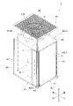
- FIG. 2 is a schematic external perspective view of a heat source unit 2.
- FIG. 2 is a schematic front view of the heat source unit 2;
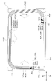
- FIG. 2 is a schematic plan view of the heat source unit 2;
- FIG. 3 is a schematic perspective view of a flow divider 80 and its surroundings, showing a state of attachment to a heat exchange section 50;
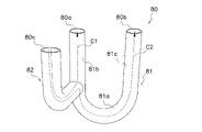
- 3 is a schematic perspective view of a flow dividing pipe 80;
- FIG. FIG. 10 is a cross-sectional view of a branch pipe 80 according to Modification 1 having a third straight portion 82a.
- the heat exchanger of the present disclosure is used, for example, as a heat exchanger for a refrigeration cycle device that uses a vapor compression refrigeration cycle, although its application is not limited.
- a case where the heat exchanger of the present disclosure is used as the heat source side heat exchanger 11 of an air conditioner 1, which is an example of a refrigeration cycle device will be described with reference to the drawings.
- an air conditioner is only an example of a refrigeration cycle device, and the heat exchanger of the present disclosure is used in other refrigeration cycle devices such as refrigerators, freezers, water heaters, floor heating devices, and the like. may
- FIG. 1 is a schematic configuration diagram of an air conditioner 1 having a heat exchanger according to an embodiment of the present disclosure as a heat source side heat exchanger 11.
- FIG. 1 is a schematic configuration diagram of an air conditioner 1 having a heat exchanger according to an embodiment of the present disclosure as a heat source side heat exchanger 11.
- the air conditioner 1 is a device that cools and heats the air-conditioned space by performing a vapor compression refrigeration cycle.
- the air-conditioned space is, for example, a space within a building such as an office building, a commercial facility, or a residence.
- the air conditioner 1 mainly controls the heat source unit 2, the utilization unit 3, the liquid refrigerant communication pipe 4, the gas refrigerant communication pipe 5, and the equipment that constitutes the heat source unit 2 and the utilization unit 3. and a control unit 23 for
- the liquid refrigerant communication pipe 4 and the gas refrigerant communication pipe 5 are refrigerant communication pipes that connect the heat source unit 2 and the utilization unit 3 .
- a refrigerant circuit 6 is configured by connecting the heat source unit 2 and the utilization unit 3 through the refrigerant communication pipes 4 and 5 .
- the air conditioner 1 has one usage unit 3, but the air conditioner 1 has a plurality of usage units 3 connected in parallel to the heat source unit 2 by refrigerant connecting pipes 4 and 5. may have Also, the air conditioner 1 may have a plurality of heat source units 2 . Also, the air conditioner 1 may be an integrated air conditioner in which the heat source unit 2 and the utilization unit 3 are integrally formed.
- the heat source unit 2 mainly includes an accumulator 7, a compressor 8, a flow direction switching mechanism 10, a heat source side heat exchanger 11, an expansion mechanism 12, a liquid side shutoff valve 13, a gas side shutoff valve 14, and a heat source. It has a side fan 15 .
- the usage unit 3 mainly includes a usage side heat exchanger 32 and a usage side fan 33 as shown in FIG.
- the operation of the air conditioner 1 will be outlined.
- the control unit 23 controls the operation of the flow direction switching mechanism 10 to change the state of the refrigerant circuit 6 so that the heat source side heat exchanger 11 functions as a refrigerant radiator (condenser) and the use side heat exchanger 32 is switched to function as a refrigerant evaporator.
- the control unit 23 controls the operation of the flow direction switching mechanism 10 to connect the suction pipe 17 connected to the suction side of the compressor 8 between the flow direction switching mechanism 10 and the gas side shutoff valve 14 . It communicates with the second gas refrigerant pipe 21 .
- control unit 23 controls the operation of the flow direction switching mechanism 10 to connect the discharge pipe 18 connected to the discharge side of the compressor 8 to the flow direction switching mechanism 10 and the gas side of the heat source side heat exchanger 11. (See the solid line in the flow direction switching mechanism 10 in FIG. 1).
- the controller 23 operates the compressor 8 , the heat source side fan 15 and the user side fan 33 .
- the control unit 23 controls the number of rotations of the motors of the compressor 8, the heat source side fan 15, and the user side fan 33, and the electronic expansion valve, which is an example of the expansion mechanism 12, based on the measured values of various sensors. is adjusted to a predetermined opening.
- the low-pressure gas refrigerant in the refrigeration cycle is sucked into the compressor 8 and compressed to a high pressure in the refrigeration cycle, and then discharged from the compressor 8 . be done.
- the high-pressure gas refrigerant discharged from the compressor 8 is sent to the heat source side heat exchanger 11 through the flow direction switching mechanism 10 .
- the high-pressure gas refrigerant sent to the heat source side heat exchanger 11 exchanges heat with air as a cooling source supplied by the heat source side fan 15 in the heat source side heat exchanger 11 functioning as a refrigerant radiator. It dissipates heat and becomes a high-pressure liquid refrigerant.
- the high-pressure liquid refrigerant that has released heat in the heat source side heat exchanger 11 is sent to the expansion mechanism 12 through the liquid refrigerant pipe 20 .
- the high-pressure liquid refrigerant is decompressed to become a low-pressure gas-liquid two-phase refrigerant.
- the low-pressure gas-liquid two-phase refrigerant decompressed by the expansion mechanism 12 is sent to the utilization side heat exchanger 32 through the liquid refrigerant pipe 20 , the liquid side shutoff valve 13 and the liquid refrigerant connecting pipe 4 .
- the low-pressure gas-liquid two-phase refrigerant sent to the user-side heat exchanger 32 is mixed with the air in the air-conditioned space supplied by the user-side fan 33 in the user-side heat exchanger 32 that functions as a refrigerant evaporator. It evaporates through heat exchange. At this time, the air that has been cooled by exchanging heat with the refrigerant is supplied to the air-conditioned space, and the air-conditioned space is cooled.
- the low-pressure gas refrigerant evaporated in the utilization side heat exchanger 32 is sucked into the compressor 8 again through the gas refrigerant communication pipe 5 , the gas side shutoff valve 14 , the flow direction switching mechanism 10 and the accumulator 7 .
- the control unit 23 controls the operation of the flow direction switching mechanism 10 to change the state of the refrigerant circuit 6 so that the heat source side heat exchanger 11 functions as a refrigerant evaporator and the use side heat exchanger 32 functions as a refrigerant evaporator. Switch to a state where it functions as a container (condenser). Specifically, the control unit 23 controls the operation of the flow direction switching mechanism 10 to communicate the suction pipe 17 with the first gas refrigerant pipe 19 and communicate the discharge pipe 18 with the second gas refrigerant pipe 21 (Fig. 1 (see broken line in flow direction switching mechanism 10). During heating operation, the controller 23 operates the compressor 8 , the heat source side fan 15 and the user side fan 33 .
- control unit 23 controls the rotational speeds of the motors of the compressor 8, the heat source side fan 15, and the user side fan 33, and the electronic expansion valve, which is an example of the expansion mechanism 12, based on the measured values of various sensors. is adjusted to a predetermined opening.
- the low-pressure gas refrigerant in the refrigeration cycle is sucked into the compressor 8 and compressed to a high pressure in the refrigeration cycle, and then 8 is discharged.
- the high-pressure gas refrigerant discharged from the compressor 8 is sent to the utilization side heat exchanger 32 through the flow direction switching mechanism 10 , the gas side shutoff valve 14 and the gas refrigerant communication pipe 5 .
- the high-pressure gas refrigerant sent to the user-side heat exchanger 32 is combined with the air and heat in the air-conditioned space supplied by the user-side fan 33 in the user-side heat exchanger 32, which functions as a radiator (condenser) for the refrigerant.
- the heat is exchanged and the heat is released to become a high-pressure liquid refrigerant.
- the air heated by exchanging heat with the refrigerant is supplied to the air-conditioned space, and the air-conditioned space is heated.
- the high-pressure liquid refrigerant that has dissipated heat in the user-side heat exchanger 32 is sent to the expansion mechanism 12 through the liquid-refrigerant communication pipe 4 , the liquid-side shutoff valve 13 , and the liquid-refrigerant pipe 20 .
- the refrigerant sent to the expansion mechanism 12 is depressurized by the expansion mechanism 12 and becomes a low-pressure gas-liquid two-phase refrigerant.
- the low-pressure gas-liquid two-phase refrigerant decompressed by the expansion mechanism 12 is sent to the heat source side heat exchanger 11 through the liquid refrigerant pipe 20 .
- the low-pressure gas-liquid two-phase refrigerant sent to the heat source side heat exchanger 11 is mixed with air as a heat source supplied by the heat source side fan 15 in the heat source side heat exchanger 11 functioning as a refrigerant evaporator. After heat exchange, it evaporates and becomes a low-pressure gas refrigerant.
- the low-pressure refrigerant evaporated in the heat source side heat exchanger 11 is sucked into the compressor 8 again through the flow direction switching mechanism 10 and the accumulator 7 .
- FIG. 2 is a schematic external perspective view of the heat source unit 2.
- FIG. FIG. 3 is a schematic front view of the heat source unit 2 (illustration of refrigerant circuit components other than the heat source side heat exchanger 11 is omitted).
- FIG. 4 is a schematic plan view of the heat source unit 2 (illustration of a fan module 44 to be described later and refrigerant circuit components other than the heat source side heat exchanger 11 is omitted).
- the heat source unit 2 is a top-blown heat exchange unit that draws in air from the sides of the casing 40 and blows air out from the top surface of the casing 40 .
- the heat source unit 2 mainly has a substantially rectangular parallelepiped box-shaped casing 40 and refrigerant circuit components that form part of the refrigerant circuit 6 .
- the refrigerant circuit components include an accumulator 7, a compressor 8, a heat source side heat exchanger 11, a flow direction switching mechanism 10, an expansion mechanism 12, a liquid side stop valve 13, a gas side stop valve 14, and the like.
- the heat source side fan 15 and refrigerant circuit components are housed in the casing 40 .
- the casing 40 mainly includes a pair of mounting legs 41 extending in the left-right direction, a bottom frame 42 spanning over the pair of mounting legs 41, a support 43, a fan module 44, and a side panel 45. and have The struts 43 extend vertically from corners of the bottom frame 42 .
- a fan module 44 is attached to the upper end of the column 43 .
- the side panel 45 is a plate-like member. The side panel 45 is arranged so as to cover the front surface and left side front side of the heat source unit 2 .
- the bottom frame 42 forms the bottom surface of the casing 40.
- the heat source side heat exchanger 11, the compressor 8, the accumulator 7, and the like are arranged on the bottom frame 42.
- the side panel 45 is a plate-shaped member extending vertically from the bottom frame 42 to the fan module 44 .
- the side panel 45 is generally arranged at a position not facing the heat exchange section 50 of the heat source side heat exchanger 11, which will be described later.
- the side panel 45 includes a front panel 45a arranged on the front side and a left side panel 45b arranged on the left side.
- the front panel 45a extends in the left-right direction from near the right end 50R of the heat exchange section 50, which will be described later, to the left front corner of the heat source unit 2.
- the left side panel 45b extends in the front-rear direction from the left front corner of the heat source unit 2 to the vicinity of the left end 50L of the heat exchange section 50.
- the fan module 44 is arranged above the heat source side heat exchanger 11 (above the casing 40).
- the fan module 44 is an assembly in which the heat source side fan 15 is accommodated in a substantially rectangular parallelepiped box having an open upper surface and a lower surface. An opening on the top surface of the fan module 44 is the air outlet 40 b of the casing 40 .
- a blowout grill 46 is provided at the air blowout port 40b.
- the heat source side fan 15 is arranged inside the casing 40 so as to face the air outlet 40b.
- the heat source side fan 15 is a blower that draws air into the casing 40 from an air intake port 40a on the side of the casing 40 and discharges air from an air outlet 40b, as indicated by arrows in FIGS.
- An air intake port 40a for air is formed on the side surface (here, front surface, rear surface, and left and right side surfaces) of the casing 40, and an air outlet 40b for air is formed on the top surface. Due to the airflow generated by the heat source side fan 15 housed in the fan module 44, the air passing through the air intake port 40a flows from the outside to the inside of the casing 40 as indicated by the arrows in FIGS. It is captured.
- the air intake 40a has an air intake 40a1 formed on the front side, an air intake 40a2 formed on the right side, an air intake 40a3 formed on the back, and an air intake 40a3 formed on the left side.
- An air intake 40a4 is included.
- the heat source side heat exchanger 11 is a heat exchanger that exchanges heat between refrigerant and outdoor air.
- the heat source side heat exchanger 11 is a cross fin type fin and tube heat exchanger.
- the heat source side heat exchanger 11 has three heat exchange sections 50 , a plurality of branch pipes 80 and a U-shaped pipe 90 .
- the heat source side heat exchanger 11 is an example of a heat exchanger.
- the heat exchange section 50, the branch pipe 80, and the U-shaped pipe 90 are made of aluminum or an aluminum alloy, and are joined together by brazing or the like.
- the heat source side heat exchanger 11 is formed in a substantially rectangular shape along the side surface of the casing 40 in plan view (see FIG. 4). However, the heat exchange section 50 of the heat source side heat exchanger 11, which will be described later, is not arranged in a portion other than the right side of the front of the heat source unit 2 and on the front left side, and the heat source side heat exchanger 11 is, in plan view, It is formed in a substantially rectangular shape with a part (left front side) missing.
- the heat exchange section 50 has an upwind heat exchange section 50a, a central heat exchange section 50b, and a leeward heat exchange section 50c.
- the windward heat exchange section 50a, the central heat exchange section 50b, and the leeward heat exchange section 50c are collectively referred to as the heat exchange section 50 as well.
- Each heat exchange section 50 is composed of a plurality of heat transfer tubes 52 extending in a predetermined shape on the horizontal plane.
- the windward heat exchange section 50a is composed of a plurality of heat transfer tubes 52a
- the central heat exchange section 50b is composed of a plurality of heat transfer tubes 52b
- the leeward heat exchange section 50c is composed of a plurality of heat transfer tubes. 52c.
- the heat transfer tubes 52a, 52b, and 52c are collectively referred to as the heat transfer tube 52 as well.
- Each heat transfer tube 52 is formed in a shape that draws a substantially rectangular shape in which each side is along the side surface of the casing 40 in plan view, and a portion other than the right front side of the heat source unit 2 and a portion corresponding to the left front side are removed. be done.
- a predetermined number of the heat transfer tubes 52 of each heat exchange section 50 are arranged in a row direction, which is the vertical direction.
- the windward heat exchange section 50a, the central heat exchange section 50b, and the leeward heat exchange section 50c are arranged side by side in the flow direction of the air generated by the heat source side fan 15.
- the air flow direction generated by the heat source side fan 15 means the air flow direction when the heat exchange section 50 is viewed from above (in plan view).
- Each heat exchange section 50 is arranged in the order of the windward heat exchange section 50a, the central heat exchange section 50b, and the leeward side heat exchange section 50c from the windward side in the flow direction of the air generated by the heat source side fan 15.
- the windward heat exchange section 50a is arranged outside the central heat exchange section 50b so as to surround the central heat exchange section 50b.
- the central heat exchange section 50b is arranged outside the leeward heat exchange section 50c so as to surround the leeward heat exchange section 50c in plan view.
- the heat transfer tubes 52 are arranged in multiple stages in the vertical direction (row direction) and arranged in multiple rows (here, three rows) in the air ventilation direction (row direction). ing.
- each heat exchange section 50 By arranging each heat exchange section 50 as described above, when the heat source side fan 15 generates an air flow, the heat exchange amount of the windward heat exchange section 50a is equal to that of the central heat exchange section 50b. The amount of heat exchanged in the central heat exchange section 50b is greater than the amount of heat exchanged in the leeward heat exchange section 50c.
- Each heat transfer tube 52 is supported by a plurality of fins 50d with a predetermined space therebetween in the vertical direction.
- a hole (not shown) for inserting the heat transfer tube 52 is formed in the fin 50d.
- the plurality of fins 50d are orthogonal to the horizontal direction and arranged at predetermined intervals in the extending direction of the heat transfer tubes 52 .
- Each heat transfer tube 52 is supported by the fins 50d by being inserted into holes formed in the fins 50d.
- the heat transfer tubes 52 are arranged vertically so that the central axes of the heat transfer tubes 52 of the heat exchange sections 50 do not overlap each other when viewed from the horizontal direction, in order to effectively perform heat exchange between the refrigerant and the outdoor air. be. Note that FIG. 4 shows only a portion of the plurality of fins 50d for convenience.
- the heat exchange unit 50 is provided with pipes at the right end 50R and the left end 50L for causing the refrigerant that has flowed into the heat transfer pipe 52 to meander and flow vertically.
- the right end 50R of the heat exchange portion 50 is an end located on the front right side of the heat source unit 2 in plan view.
- 50 L of left ends of the heat exchange part 50 are edge parts located in front of the left surface of the heat-source unit 2 in planar view.
- a plurality of U-shaped tubes 90 are provided at the right end portion 52R, which is the end portion of the heat transfer tube 52 positioned at the right end 50R.
- a plurality of branch pipes 80 are provided at the left end portion 52L, which is the end portion of the heat transfer tube 52 located at the left end 50L.
- the U-tube 90 is a pipe that connects the right end 52bR of the heat transfer tube 52b and the right end 52cR of the heat transfer tube 52c in a predetermined stage, and the right end 50aR of the heat transfer tube 52a in the upper stage. .
- the refrigerant flowing out from the right end portion 52bR of the heat transfer tube 52b and the right end portion 52cR of the heat transfer tube 52c of a predetermined stage flows through the U-shaped tube 90 to the stage one stage above. flow into the windward heat exchange section 50a.
- the branch pipe 80 is a pipe that connects the left end 52aL of the heat transfer tube 52a in a given stage, the left end 52bL of the heat transfer tube 52b in the same stage, and the left end 52cL of the heat transfer tube 52c. Details of the flow dividing pipe 80 will be described later.
- the heat transfer tube 52a that constitutes the windward heat exchange section 50a is an example of a third heat transfer tube.
- the heat transfer tubes 52b forming the central heat exchange section 50b are an example of first heat transfer tubes.
- the heat transfer tube 52c forming the leeward heat exchange section 50c is an example of a second heat transfer tube.
- the flow division pipe 80 divides the refrigerant flowing out of the heat transfer pipe 52a of the windward heat exchange section 50a to transfer the refrigerant to the heat transfer pipe 52b of the central heat exchange section 50b and the leeward heat exchange section 50c. It is a pipe for flowing into the heat pipe 52c.
- the branch pipe 80 is a branch pipe having three ends, a first end 80a, a second end 80b, and a third end 80c, which are connected to each other.
- FIG. 5 is a schematic perspective view of the flow dividing pipe 80 and its surroundings, showing the state of attachment to the heat exchange section 50.
- FIG. FIG. 6 is a schematic perspective view of the flow dividing tube 80. As shown in FIG.
- the branch pipe 80 has a U-shaped portion 81 and an inflow portion 82 .
- the U-shaped portion 81 and the inflow portion 82 are pipes having the same inner diameter and different shapes.
- the U-shaped portion 81 splits the refrigerant that has flowed in from the inflow portion 82 into two and flows them into the heat transfer tubes 52b and 52c.
- the U-shaped portion 81 is composed of a bent portion 81a, a first straight portion 81b, and a second straight portion 81c.
- the bent portion 81a is a portion bent with a predetermined radius.
- the first straight portion 81b is a portion linearly extending a predetermined length from one end of the bent portion 81a.
- the second straight portion 81c is a portion extending linearly for a predetermined length from the other end of the bent portion 81a.
- the first end 80a is the end of the first linear portion 81b opposite to the bent portion 81a.
- the second end 80b is the end of the second linear portion 81c opposite to the bent portion 81a.
- the inflow portion 82 causes the refrigerant that has flowed out from the heat transfer tubes 52 a of the windward heat exchange portion 50 a to flow into the U-shaped portion 81 .
- One end of the inflow portion 82 is connected to the first linear portion 81b.
- the third end 80c is the end of the inflow portion 82 opposite to the first linear portion 81b.
- the channels through which the coolant flows in the branch pipe 80 include the first channel C1 and the second channel C2.
- the first flow path C1 is a flow path that connects the first end portion 80a and the third end portion 80c and includes the inflow portion 82 and part of the first straight portion 81b therebetween.
- the first flow path C1 is indicated by a two-dot chain line in FIG.
- the second flow path C2 is a flow path connecting the second end 80b and the third end 80c and including the inflow portion 82, part of the bent portion 81a, and the second straight portion 81c therebetween.
- the second flow path C2 is indicated by dashed lines in FIG.
- the flow dividing pipe 80 is formed such that the length of the first flow path C1 is shorter than that of the second flow path C2.
- the ratio of the length of the first flow path C1 and the length of the second flow path C2 of the flow dividing tube 80 is the ratio of the heat exchange amount of the heat transfer tube 52b to which the flow dividing tube 80 is connected to the heat transfer amount of the heat transfer tube 52c.
- the ratio between the length of the first flow path C1 and the length of the second flow path C2 is the same as the ratio between the heat exchange amount of the heat transfer tube 52b to which the branch tube 80 is connected and the heat transfer amount of the heat transfer tube 52c.
- the flow dividing tube 80 connects the left end 52aL of the heat transfer tube 52a with the left end 52bL of the heat transfer tube 52b and the left end 52cL2 of the heat transfer tube 52c arranged in the same stage. More specifically, the first end 80a of the flow dividing tube 80 is connected to the left end 52bL of the heat transfer tube 52b. Also, the second end 80b of the flow dividing tube 80 is connected to the left end 52cL of the heat transfer tube 52c. Furthermore, the third end 80c of the flow dividing tube 80 is connected to the left end 52aL of the heat transfer tube 52a.
- gas-liquid two-phase refrigerant flows from the liquid refrigerant pipe 20 into the lowermost heat transfer pipe 52 .
- the heat transfer tube into which the refrigerant flows may be either the heat transfer tube 52b of the central heat exchange section 50b or the heat transfer tube 52c of the leeward heat exchange section 50c.
- the refrigerant that has flowed into the heat transfer tube 52 from the left end 52L flows through the heat transfer tube 52 to the right end 52R side, and then passes through the U-shaped tube 90 to the windward heat exchange located one stage above.
- the refrigerant that has flowed into the branch pipe 80 passes through the inflow portion 82 and then flows into the U-shaped portion 81 to be branched.
- the refrigerant flowing into the branch pipe 80 is divided into the refrigerant flowing through the first flow path C1 and the refrigerant flowing through the second flow path C2.
- the coolant flowing through the first flow path C1 passes through the inflow portion 82, flows into the first straight portion 81b, and flows out from the first end portion 80a.
- the refrigerant that has flowed out from the first end portion 80a flows into the heat transfer tubes 52b of the central heat exchange portion 50b.
- the coolant flowing through the second flow path C2 passes through the inflow portion 82 and flows into the bent portion 81a, then passes through the second straight portion 81c and flows out from the second end portion 80b.
- the refrigerant that has flowed out from the second end portion 80b flows into the heat transfer tubes 52c of the leeward heat exchange portion 50c.
- the refrigerant flowing from the heat transfer tube 52a into the branch tube 80 flows through the branch tube 80 and then into the heat transfer tubes 52b and 52c in the same stage as the heat transfer tube 52a.
- the refrigerant that has flowed into the heat transfer tubes 52b and 52c flows toward the right end portions 50bR and 50cR, passes through the U-shaped tube 90, and flows into the heat transfer tube 52a one stage above.
- the refrigerant that has flowed into the heat transfer tube 52a flows through the heat transfer tube 52a to the left end 50aL, then flows into the flow dividing tube 80 connected to the left end 52aL, and again flows into the heat transfer tube 52b in the same stage as the heat transfer tube 52a. 52c.
- the refrigerant that has flowed into the heat exchange section 50 from the liquid refrigerant pipe 20 flows upward while meandering inside the heat transfer pipe 52 . After that, the refrigerant flows out from the heat transfer pipes 52 a of a predetermined stage, flows outside the heat source side heat exchanger 11 , and flows into the first gas refrigerant pipes 19 .
- the heat source side heat exchanger 11 of the present disclosure includes a central heat exchange section 50b (first heat transfer tube), a leeward side heat exchange section 50c (second heat transfer tube), and a flow dividing tube 80.
- the branch pipe 80 has a first end 80a connected to the end of the central heat exchange section 50b, a second end 80b connected to the end of the leeward heat exchange section 50c, and a third end 80c. have.
- a flow dividing tube 80 connects a first end 80a, a second end 80b, and a third end 80c to each other.
- the amount of heat exchanged in the central heat exchange section 50b is greater than the amount of heat exchanged in the leeward heat exchange section 50c.
- the length of the first flow path C1 connecting the first end 80a and the third end 80c is longer than the length of the second flow path C2 connecting the second end 80b and the third end 80c. short.
- the length of the first flow path C1 is shorter than that of the second flow path C2. It is small compared to the pressure loss received. Therefore, the flow rate of the refrigerant flowing through the flow dividing pipe 80 into the heat transfer pipe 52b is greater than that of the refrigerant flowing through the flow dividing pipe 80 into the heat transfer pipe 52c.
- the heat source side heat exchanger 11 it is possible to improve the capacity while suppressing the increase in manufacturing cost by using the branch pipe 80 having a simple structure.
- the ratio between the length of the first flow path C1 and the length of the second flow path C2 of the flow dividing tube 80 is the amount of heat exchanged in the heat transfer tube 52b to which the flow dividing tube 80 is connected. It may be formed so as to correspond to the ratio with the heat exchange amount of 52c.
- the amount of refrigerant flowing out from the first end portion 80a and the amount of refrigerant flowing out from the second end portion 80b depend on the pressure received by the refrigerant in the first flow path C1. It is determined by the loss and the pressure loss received by the refrigerant in the second flow path C2. Therefore, the ratio between the amount of refrigerant flowing into the heat transfer tube 52b and the amount of refrigerant flowing into the heat transfer tube 52c is determined by the ratio between the length of the first flow path C1 and the length of the second flow path C2. .
- the ratio of the length of the first flow path C1 to the length of the second flow path C2 is the ratio of the heat exchange amount of the heat transfer tube 52b to which the branch tube 80 is connected to the heat exchange amount of the heat transfer tube 52c.
- the difference in degree of superheat between the heat transfer tube 52b and the heat transfer tube 5250c can be reduced by the branch tube 80, and the heat source side heat exchanger 11 with higher capacity can be provided.
- the branch pipe 80 has a U-shaped portion 81 and an inflow portion 82 having one end connected to the U-shaped portion 81 .
- the U-shaped portion 81 has a bent portion 81a, a first straight portion 81b and a second straight portion 81c.
- the bent portion 81a is bent with a predetermined radius.
- the first linear portion 81b extends linearly from one end of the bent portion 81a.
- the second linear portion 81c extends linearly from the other end of the bent portion 81a.
- the end portion of the first linear portion 81b opposite to the bent portion 81a is the first end portion 80a.
- the end portion of the second linear portion 81c opposite to the bent portion 81a is the second end portion 80b.
- One end of the inflow portion 82 is connected to the first linear portion 81b, and the other end is the third end portion 80c.
- the first flow path C1 includes an inflow portion 82 and part of the first linear portion 81b.
- the second flow path C2 includes an inflow portion 82, a portion of the bent portion 81a, and a second straight portion 81c.
- the branch pipe 80 since the branch pipe 80 has a simple structure consisting of the U-shaped portion 81 and the inflow portion 82, it can be manufactured at low cost. Also, the lengths of the first flow path C1 and the second flow path C2 can be easily adjusted by changing the attachment position of the inflow portion 82 to the U-shaped portion 81 .
- the inflow portion 82 may have a third linear portion 82a linearly extending from a portion connected to the first linear portion 81b.
- FIG. 7 is a cross-sectional view of a branch pipe 80 according to Modification 1 having a third straight portion 82a.
- FIG. 7 is a cross-sectional view of the branch pipe 80 according to Modification 1 taken along a plane including the first straight portion 81b and the third straight portion 82a.
- the angle ⁇ is preferably 90° or more and 135° or less.
- the coolant passing through the first flow path C1 smoothly flows from the inflow portion 82 into the first linear portion 81b, compared to when the angle ⁇ is smaller than 90°. Therefore, a large flow rate of the refrigerant flowing into the heat transfer tubes 52b is ensured, and the heat source side heat exchanger 11 with higher capacity can be provided.
- the third end portion 80c may be connected to the first gas refrigerant pipe 19 or the liquid refrigerant pipe 20, and the first end portion 80a and the second end portion 80b may be connected to the heat transfer pipes 52 having different heat exchange amounts.
- the flow rate of the refrigerant flowing into the two heat transfer tubes 52 through the first gas refrigerant pipe 19 or the liquid refrigerant pipe 20 can be made different from each other by the flow dividing pipe 80 , whereby the two heat transfer pipes 52 It is possible to suppress the deterioration of the performance of the heat exchange section 50 due to the difference in the amount of heat exchanged between.
Abstract
Provided is a heat exchanger that can suppress increases in production costs and improve performance. This heat exchanger comprises a first heat transfer pipe, a second heat transfer pipe, and a branch pipe. The branch pipe has a first end section connected to an end of the first heat transfer pipe and second and third end sections that are connected to the second heat transfer pipe. The branch pipe connects the first end section, the second end section, and the third end section to each other. The amount of heat exchanged by the first heat transfer pipe is greater than the amount of heat exchanged by the second heat transfer pipe. In the branch pipe, a first flow path that connects the first end section and the third end section is shorter than a second flow path that connects the second end section and the third end section.
Description
熱交換器に関する。
Regarding the heat exchanger.
空気調和装置の冷媒回路を構成する熱交換器が知られている。
A heat exchanger that constitutes a refrigerant circuit of an air conditioner is known.
特許文献1(特開平1-305276号公報)は、複数の配管(伝熱管)と、配管に接続された分岐管とを備える熱交換器を開示する。特許文献1の熱交換器では、複数の配管は、ファンにより生成される風の風上側と風下側とに並べて配置される。また、分岐管は、1つの入口管と2つの分岐口とを備え、入口管から流入した冷媒を2つの分岐口を通じて風上側に配置された配管と風下側に配置された配管とへ流す。
Patent Document 1 (JP-A-1-305276) discloses a heat exchanger comprising a plurality of pipes (heat transfer pipes) and branch pipes connected to the pipes. In the heat exchanger of Patent Document 1, the plurality of pipes are arranged side by side on the windward side and the leeward side of the wind generated by the fan. In addition, the branch pipe has one inlet pipe and two branch ports, and the refrigerant flowing from the inlet pipe flows through the two branch ports to the pipe arranged on the windward side and the pipe arranged on the leeward side.
特許文献1の熱交換器では、分岐管の2つの分岐口には、互いに流路径が異なるオリフィスが取り付けられているため、風上側の配管と風下側の配管とで流れ込む冷媒の流量を異ならせることができる。このため、特許文献1の熱交換器によれば、風上側の配管及び風下側の配管それぞれで発生する過熱度の差を抑止して、熱交換器の能力が低下することを抑制できる。
In the heat exchanger of Patent Document 1, orifices having different flow path diameters are attached to the two branch ports of the branch pipe, so that the flow rate of the refrigerant flowing into the pipe on the windward side and the pipe on the leeward side are made to differ. be able to. Therefore, according to the heat exchanger of Patent Literature 1, it is possible to suppress the difference in degree of superheat generated between the pipes on the windward side and the pipes on the leeward side, thereby suppressing a decrease in the performance of the heat exchanger.
特許文献1に開示される熱交換器の場合、分岐管にオリフィスを取り付ける必要があるため、製造コストを抑えることが困難である。
In the case of the heat exchanger disclosed in Patent Document 1, it is difficult to reduce the manufacturing cost because it is necessary to attach orifices to the branch pipes.
本開示は、製造コストが上昇することを抑制しながら、能力の向上を図ることができる熱交換器を提案する。
The present disclosure proposes a heat exchanger capable of improving capacity while suppressing increases in manufacturing costs.
第1観点の熱交換器は、第1伝熱管と、第2伝熱管と、分流管と、を備える。分流管は、第1伝熱管の端部に接続された第1端部、第2伝熱管の端部に接続された第2端部及び第3端部を有する。分流管は、第1端部、第2端部及び第3端部を互いに接続する。第1伝熱管の熱交換量は、第2伝熱管における熱交換量よりも多い。分流管は、第1端部と第3端部とをつなぐ第1流路の長さが、第2端部と第3端部とをつなぐ第2流路よりも短い。
The heat exchanger of the first aspect includes a first heat transfer tube, a second heat transfer tube, and a flow dividing tube. The flow dividing tube has a first end connected to the end of the first heat transfer tube, a second end connected to the end of the second heat transfer tube, and a third end. A flow diverter tube connects the first end, the second end and the third end to each other. The amount of heat exchanged in the first heat transfer tube is greater than the amount of heat exchanged in the second heat transfer tube. In the flow dividing tube, the length of the first flow path connecting the first end and the third end is shorter than the length of the second flow path connecting the second end and the third end.
本開示に係る熱交換器では、第1流路の長さが第2流路よりも短いため、第1流路を流れる冷媒が受ける圧力損失は、第2流路を流れる冷媒が受ける圧力損失に比べて小さい。このため、分流管を通って第1伝熱管に流入する冷媒は、分流管を通って第2伝熱管に流入する冷媒に比べて流量が多くなる。
In the heat exchanger according to the present disclosure, since the length of the first flow path is shorter than that of the second flow path, the pressure loss suffered by the refrigerant flowing through the first flow path is the pressure loss suffered by the refrigerant flowing through the second flow path. small compared to Therefore, the flow rate of the refrigerant flowing through the branch pipe into the first heat transfer tube is greater than that of the refrigerant flowing into the second heat transfer pipe through the branch pipe.
この結果、第1伝熱管の熱交換量が第2伝熱管の熱交換量よりも多くても、第1伝熱管で発生する過熱度と第2伝熱管で発する過熱度との差が大きくなることが抑制される。このため、第1伝熱管と第2伝熱管との間での過熱度の違いにより、熱交換器の能力が低下することが抑制される。
As a result, even if the amount of heat exchanged in the first heat transfer tube is greater than that in the second heat transfer tube, the difference between the degree of superheat generated in the first heat transfer tube and the degree of superheat generated in the second heat transfer tube increases. is suppressed. Therefore, a decrease in the performance of the heat exchanger due to the difference in the degree of superheat between the first heat transfer tube and the second heat transfer tube is suppressed.
したがって、熱交換器によれば、シンプルな構造の分流管を用いて製造コストが上昇することを抑制しながら、能力の向上を図ることができる。
Therefore, according to the heat exchanger, it is possible to improve the capacity while suppressing the increase in manufacturing cost by using the branch pipe with a simple structure.
第2観点の熱交換器は、第1観点の熱交換器であって、第1伝熱管が、第2伝熱管よりも風上側に配置されている。
The heat exchanger of the second aspect is the heat exchanger of the first aspect, in which the first heat transfer tubes are arranged on the windward side of the second heat transfer tubes.
第3観点の熱交換器は、第1観点または第2観点の熱交換器であって、第3端部に接続された第3伝熱管をさらに備える。
The heat exchanger of the third aspect is the heat exchanger of the first aspect or the second aspect, further comprising a third heat transfer tube connected to the third end.
第4観点の熱交換器は、第3観点の熱交換器であって、第3伝熱管は、第1伝熱管よりも風上側に配置されている。
The heat exchanger according to the fourth aspect is the heat exchanger according to the third aspect, and the third heat transfer tube is arranged on the windward side of the first heat transfer tube.
第5観点の熱交換器は、第1観点から第4観点のいずれかの熱交換器であって、第1流路の長さと第2流路の長さとの比が、第1伝熱管の熱交換量と第2伝熱管の熱交換量の比に対応する。
A heat exchanger according to a fifth aspect is the heat exchanger according to any one of the first aspect to the fourth aspect, wherein the ratio of the length of the first flow path to the length of the second flow path is the length of the first heat transfer tube. It corresponds to the ratio of the heat exchange amount and the heat exchange amount of the second heat transfer tube.
本開示に係る熱交換器では、第1端部から流出する冷媒の量と、第2端部から流出する冷媒の量とは、第1流路で冷媒が受ける圧力損失と、第2流路で冷媒が受ける圧力損失とにより決まる。このため、第1伝熱管に流入する冷媒の量と、第2伝熱管に流入する冷媒の量との比は、第1流路の長さと第2流路の長さとの比によって決定される。
In the heat exchanger according to the present disclosure, the amount of refrigerant flowing out from the first end and the amount of refrigerant flowing out from the second end are the pressure loss received by the refrigerant in the first flow path and the pressure loss in the second flow path. It is determined by the pressure loss that the refrigerant receives at Therefore, the ratio between the amount of refrigerant flowing into the first heat transfer tube and the amount of refrigerant flowing into the second heat transfer tube is determined by the ratio of the length of the first flow path to the length of the second flow path. .
したがって、たとえば、第1流路の長さと第2流路の長さとの比を、第1伝熱管の熱交換量と第2伝熱管の熱交換量との比と同じにすることにより、分流管によって中央熱交換部と風下側熱交換部との間での過熱度の違いを小さくすることができ、より高い能力の熱交換器を提供できる。
Therefore, for example, by setting the ratio of the length of the first flow path to the length of the second flow path to be the same as the ratio of the heat exchange amount of the first heat transfer tube to the heat exchange amount of the second heat transfer tube, The tubes can reduce the difference in superheat between the central heat exchange section and the leeward heat exchange section, providing a higher capacity heat exchanger.
第6観点の熱交換器は、第1観点から第5観点のいずれかの熱交換器であって、分流管は、U字部と、一端がU字部に接続された流入部とを有する。U字部は、屈曲部、第1直線部及び第2直線部を有する。屈曲部は、所定の半径で屈曲する。第1直線部は、屈曲部の一端から直線状に伸びる。第2直線部は、屈曲部の他端から直線状に伸びる。第1直線部の屈曲部と反対側の端部が第1端部である。第2直線部の屈曲部と反対側の端部が第2端部である。流入部は、一端が第1直線部に接続され、他端が第3端部である。第1流路は、流入部および第1直線部の一部を含む。第2流路は、流入部、屈曲部の一部及び第2直線部を含む。
A heat exchanger according to a sixth aspect is the heat exchanger according to any one of the first aspect to the fifth aspect, wherein the branch pipe has a U-shaped portion and an inflow portion having one end connected to the U-shaped portion. . The U-shaped portion has a bent portion, a first straight portion and a second straight portion. The bending portion bends with a predetermined radius. The first linear portion extends linearly from one end of the bent portion. The second straight portion extends linearly from the other end of the bent portion. The end of the first linear portion opposite to the bent portion is the first end. The end of the second linear portion opposite to the bent portion is the second end. The inflow portion has one end connected to the first straight portion and the other end serving as the third end. The first flow path includes an inflow portion and a portion of the first straight portion. The second flow path includes an inflow portion, a portion of the curved portion, and a second straight portion.
本開示に係る熱交換器では、分流管は、U字部と、流入部とからなるシンプルな構造であるため、低コストでの製造が可能である。また、第1流路及び第2流路の長さは、流入部のU字部への取り付け位置を変更することで容易に調整される。
In the heat exchanger according to the present disclosure, the branch pipe has a simple structure consisting of the U-shaped portion and the inflow portion, so it can be manufactured at low cost. Also, the lengths of the first flow path and the second flow path can be easily adjusted by changing the attachment position of the inflow portion to the U-shaped portion.
第7観点の熱交換器は、第6観点の熱交換器であって、第1直線部に接続された箇所から直線状に伸びる第3直線部を有する。第1直線部の中心軸と第3直線部の中心軸とを含む平面において、第3直線部の中心軸と第1直線部の中心軸とがなす角のうち、第1端部側の角は、90°以上135°以下である。
The heat exchanger according to the seventh aspect is the heat exchanger according to the sixth aspect, and has a third straight portion linearly extending from a portion connected to the first straight portion. Of the angles formed by the central axis of the third straight portion and the central axis of the first straight portion in the plane containing the central axis of the first straight portion and the central axis of the third straight portion, the angle on the first end side is 90° or more and 135° or less.
第3直線部の中心軸と第1直線部の中心軸とがなす角の角度が上記の範囲で形成されることにより、当該角度が90°より小さい場合と比較して、第1流路を通る冷媒は、流入部から滑らかに第1直線部に流れ込む。このため、第1伝熱管に流入する冷媒の流量が多く確保され、より高い能力の熱交換器を提供できる。
By forming the angle formed by the central axis of the third straight portion and the central axis of the first straight portion within the above range, the first flow path is more flexible than when the angle is smaller than 90°. The coolant passing through smoothly flows into the first linear portion from the inflow portion. Therefore, a large flow rate of the refrigerant flowing into the first heat transfer tubes is ensured, and a heat exchanger with higher capacity can be provided.
本開示の熱交換器は、用途を限定するものではないが、例えば、蒸気圧縮式の冷凍サイクルを利用する冷凍サイクル装置の熱交換器として使用される。ここでは、本開示の熱交換器が、冷凍サイクル装置の一例である空気調和装置1の熱源側熱交換器11として使用される場合について、図面を参照しながら説明する。なお、空気調和装置は、冷凍サイクル装置の一例に過ぎず、本開示の熱交換器は、他の冷凍サイクル装置、例えば、冷蔵庫、冷凍庫、給湯器、床暖房装置等に使用されるものであってもよい。
The heat exchanger of the present disclosure is used, for example, as a heat exchanger for a refrigeration cycle device that uses a vapor compression refrigeration cycle, although its application is not limited. Here, a case where the heat exchanger of the present disclosure is used as the heat source side heat exchanger 11 of an air conditioner 1, which is an example of a refrigeration cycle device, will be described with reference to the drawings. Note that an air conditioner is only an example of a refrigeration cycle device, and the heat exchanger of the present disclosure is used in other refrigeration cycle devices such as refrigerators, freezers, water heaters, floor heating devices, and the like. may
以下では、初めに熱源側熱交換器11を有する空気調和装置1に関して説明する。その後に熱源側熱交換器11の詳細について説明する。
Below, the air conditioner 1 having the heat source side heat exchanger 11 will be described first. After that, the details of the heat source side heat exchanger 11 will be described.
(1)空気調和装置の構成
空気調和装置1について図面を参照しながら説明する。図1は、本開示の実施形態に係る熱交換器を熱源側熱交換器11として有する空気調和装置1の概略構成図である。 (1) Configuration of Air Conditioner Theair conditioner 1 will be described with reference to the drawings. FIG. 1 is a schematic configuration diagram of an air conditioner 1 having a heat exchanger according to an embodiment of the present disclosure as a heat source side heat exchanger 11. FIG.
空気調和装置1について図面を参照しながら説明する。図1は、本開示の実施形態に係る熱交換器を熱源側熱交換器11として有する空気調和装置1の概略構成図である。 (1) Configuration of Air Conditioner The
空気調和装置1は、蒸気圧縮式の冷凍サイクルを行うことにより、空調対象空間の冷房及び暖房を行う装置である。空調対象空間は、例えば、オフィスビル、商業施設、住居等の建物内の空間である。
The air conditioner 1 is a device that cools and heats the air-conditioned space by performing a vapor compression refrigeration cycle. The air-conditioned space is, for example, a space within a building such as an office building, a commercial facility, or a residence.
空気調和装置1は、図1のように、主として、熱源ユニット2と、利用ユニット3と、液冷媒連絡管4及びガス冷媒連絡管5と、熱源ユニット2及び利用ユニット3を構成する機器を制御する制御部23と、を有する。液冷媒連絡管4及びガス冷媒連絡管5は、熱源ユニット2と利用ユニット3とを接続する冷媒連絡管である。空気調和装置1では、熱源ユニット2と利用ユニット3とが冷媒連絡管4、5を介して接続されることで、冷媒回路6が構成される。
The air conditioner 1, as shown in FIG. 1, mainly controls the heat source unit 2, the utilization unit 3, the liquid refrigerant communication pipe 4, the gas refrigerant communication pipe 5, and the equipment that constitutes the heat source unit 2 and the utilization unit 3. and a control unit 23 for The liquid refrigerant communication pipe 4 and the gas refrigerant communication pipe 5 are refrigerant communication pipes that connect the heat source unit 2 and the utilization unit 3 . In the air conditioner 1 , a refrigerant circuit 6 is configured by connecting the heat source unit 2 and the utilization unit 3 through the refrigerant communication pipes 4 and 5 .
なお、図1では、空気調和装置1は利用ユニット3を1台有するが、空気調和装置1は、冷媒連絡管4、5によって熱源ユニット2に対して互いに並列に接続される複数の利用ユニット3を有してもよい。また、空気調和装置1は複数の熱源ユニット2を有してもよい。また、空気調和装置1は、熱源ユニット2と利用ユニット3とが一体に形成された、一体型の空気調和装置であってもよい。
In FIG. 1, the air conditioner 1 has one usage unit 3, but the air conditioner 1 has a plurality of usage units 3 connected in parallel to the heat source unit 2 by refrigerant connecting pipes 4 and 5. may have Also, the air conditioner 1 may have a plurality of heat source units 2 . Also, the air conditioner 1 may be an integrated air conditioner in which the heat source unit 2 and the utilization unit 3 are integrally formed.
熱源ユニット2は、図1のように、主として、アキュムレータ7、圧縮機8、流向切換機構10、熱源側熱交換器11、膨張機構12、液側閉鎖弁13及びガス側閉鎖弁14、及び熱源側ファン15を有している。利用ユニット3は、図1のように、利用側熱交換器32及び利用側ファン33を主に有する。
As shown in FIG. 1, the heat source unit 2 mainly includes an accumulator 7, a compressor 8, a flow direction switching mechanism 10, a heat source side heat exchanger 11, an expansion mechanism 12, a liquid side shutoff valve 13, a gas side shutoff valve 14, and a heat source. It has a side fan 15 . The usage unit 3 mainly includes a usage side heat exchanger 32 and a usage side fan 33 as shown in FIG.
空気調和装置1の動作について概説する。
The operation of the air conditioner 1 will be outlined.
冷房運転時には、制御部23は、流向切換機構10の動作を制御して、冷媒回路6の状態を熱源側熱交換器11が冷媒の放熱器(凝縮器)として機能し利用側熱交換器32が冷媒の蒸発器として機能する状態に切り換える。具体的には、制御部23は、流向切換機構10の動作を制御して、圧縮機8の吸入側に接続される吸入管17を、流向切換機構10とガス側閉鎖弁14とを接続する第2ガス冷媒管21と連通させる。また、制御部23は、流向切換機構10の動作を制御して、圧縮機8の吐出側に接続される吐出管18を、流向切換機構10と熱源側熱交換器11のガス側とを接続する第1ガス冷媒管19と連通させる(図1の流向切換機構10内の実線参照)。冷房運転時には、制御部23は、圧縮機8、熱源側ファン15及び利用側ファン33を運転する。また、冷房運転時には、制御部23は、各種センサの計測値等に基づき、圧縮機8、熱源側ファン15及び利用側ファン33のモータの回転数や、膨張機構12の一例である電子膨張弁の開度を所定開度に調節する。
During cooling operation, the control unit 23 controls the operation of the flow direction switching mechanism 10 to change the state of the refrigerant circuit 6 so that the heat source side heat exchanger 11 functions as a refrigerant radiator (condenser) and the use side heat exchanger 32 is switched to function as a refrigerant evaporator. Specifically, the control unit 23 controls the operation of the flow direction switching mechanism 10 to connect the suction pipe 17 connected to the suction side of the compressor 8 between the flow direction switching mechanism 10 and the gas side shutoff valve 14 . It communicates with the second gas refrigerant pipe 21 . Further, the control unit 23 controls the operation of the flow direction switching mechanism 10 to connect the discharge pipe 18 connected to the discharge side of the compressor 8 to the flow direction switching mechanism 10 and the gas side of the heat source side heat exchanger 11. (See the solid line in the flow direction switching mechanism 10 in FIG. 1). During cooling operation, the controller 23 operates the compressor 8 , the heat source side fan 15 and the user side fan 33 . Further, during cooling operation, the control unit 23 controls the number of rotations of the motors of the compressor 8, the heat source side fan 15, and the user side fan 33, and the electronic expansion valve, which is an example of the expansion mechanism 12, based on the measured values of various sensors. is adjusted to a predetermined opening.
制御部23が空気調和装置1の各種機器の動作を制御すると、冷凍サイクルの低圧のガス冷媒は、圧縮機8に吸入されて冷凍サイクルの高圧になるまで圧縮された後に、圧縮機8から吐出される。圧縮機8から吐出された高圧のガス冷媒は、流向切換機構10を通じて、熱源側熱交換器11に送られる。熱源側熱交換器11に送られた高圧のガス冷媒は、冷媒の放熱器として機能する熱源側熱交換器11において、熱源側ファン15により供給される冷却源としての空気と熱交換を行って放熱して、高圧の液冷媒になる。熱源側熱交換器11において放熱した高圧の液冷媒は、液冷媒管20を通って膨張機構12へと送られる。膨張機構12では、高圧の液冷媒が減圧され、低圧の気液二相状態の冷媒になる。膨張機構12で減圧された低圧の気液二相状態の冷媒は、液冷媒管20、液側閉鎖弁13及び液冷媒連絡管4を通じて、利用側熱交換器32に送られる。利用側熱交換器32に送られた低圧の気液二相状態の冷媒は、冷媒の蒸発器として機能する利用側熱交換器32において、利用側ファン33によって供給される空調対象空間の空気と熱交換を行って蒸発する。この際、冷媒と熱交換して冷却された空気は、空調対象空間に供給され、空調対象空間の冷房が行われる。利用側熱交換器32において蒸発した低圧のガス冷媒は、ガス冷媒連絡管5、ガス側閉鎖弁14、流向切換機構10及びアキュムレータ7を通じて、再び圧縮機8に吸入される。
When the control unit 23 controls the operation of various devices of the air conditioner 1 , the low-pressure gas refrigerant in the refrigeration cycle is sucked into the compressor 8 and compressed to a high pressure in the refrigeration cycle, and then discharged from the compressor 8 . be done. The high-pressure gas refrigerant discharged from the compressor 8 is sent to the heat source side heat exchanger 11 through the flow direction switching mechanism 10 . The high-pressure gas refrigerant sent to the heat source side heat exchanger 11 exchanges heat with air as a cooling source supplied by the heat source side fan 15 in the heat source side heat exchanger 11 functioning as a refrigerant radiator. It dissipates heat and becomes a high-pressure liquid refrigerant. The high-pressure liquid refrigerant that has released heat in the heat source side heat exchanger 11 is sent to the expansion mechanism 12 through the liquid refrigerant pipe 20 . In the expansion mechanism 12, the high-pressure liquid refrigerant is decompressed to become a low-pressure gas-liquid two-phase refrigerant. The low-pressure gas-liquid two-phase refrigerant decompressed by the expansion mechanism 12 is sent to the utilization side heat exchanger 32 through the liquid refrigerant pipe 20 , the liquid side shutoff valve 13 and the liquid refrigerant connecting pipe 4 . The low-pressure gas-liquid two-phase refrigerant sent to the user-side heat exchanger 32 is mixed with the air in the air-conditioned space supplied by the user-side fan 33 in the user-side heat exchanger 32 that functions as a refrigerant evaporator. It evaporates through heat exchange. At this time, the air that has been cooled by exchanging heat with the refrigerant is supplied to the air-conditioned space, and the air-conditioned space is cooled. The low-pressure gas refrigerant evaporated in the utilization side heat exchanger 32 is sucked into the compressor 8 again through the gas refrigerant communication pipe 5 , the gas side shutoff valve 14 , the flow direction switching mechanism 10 and the accumulator 7 .
暖房運転時には、制御部23は、流向切換機構10の動作を制御して、冷媒回路6の状態を熱源側熱交換器11が冷媒の蒸発器として機能し利用側熱交換器32が冷媒の放熱器(凝縮器)として機能する状態に切り換える。具体的には、制御部23は、流向切換機構10の動作を制御して、吸入管17を第1ガス冷媒管19と連通させ、吐出管18を第2ガス冷媒管21と連通させる(図1の流向切換機構10内の破線参照)。暖房運転時には、制御部23は、圧縮機8、熱源側ファン15及び利用側ファン33を運転する。また、暖房運転時には、制御部23は、各種センサの計測値等に基づき、圧縮機8、熱源側ファン15及び利用側ファン33のモータの回転数や、膨張機構12の一例である電子膨張弁の開度を所定の開度に調節する。
During heating operation, the control unit 23 controls the operation of the flow direction switching mechanism 10 to change the state of the refrigerant circuit 6 so that the heat source side heat exchanger 11 functions as a refrigerant evaporator and the use side heat exchanger 32 functions as a refrigerant evaporator. Switch to a state where it functions as a container (condenser). Specifically, the control unit 23 controls the operation of the flow direction switching mechanism 10 to communicate the suction pipe 17 with the first gas refrigerant pipe 19 and communicate the discharge pipe 18 with the second gas refrigerant pipe 21 (Fig. 1 (see broken line in flow direction switching mechanism 10). During heating operation, the controller 23 operates the compressor 8 , the heat source side fan 15 and the user side fan 33 . Further, during heating operation, the control unit 23 controls the rotational speeds of the motors of the compressor 8, the heat source side fan 15, and the user side fan 33, and the electronic expansion valve, which is an example of the expansion mechanism 12, based on the measured values of various sensors. is adjusted to a predetermined opening.
制御部23がこのように空気調和装置1の各種機器の動作を制御すると、冷凍サイクルの低圧のガス冷媒は、圧縮機8に吸入されて冷凍サイクルの高圧になるまで圧縮された後に、圧縮機8から吐出される。圧縮機8から吐出された高圧のガス冷媒は、流向切換機構10、ガス側閉鎖弁14及びガス冷媒連絡管5を通じて、利用側熱交換器32に送られる。利用側熱交換器32に送られた高圧のガス冷媒は、冷媒の放熱器(凝縮器)として機能する利用側熱交換器32において、利用側ファン33により供給される空調対象空間の空気と熱交換を行って放熱して、高圧の液冷媒になる。この際、冷媒と熱交換して加熱された空気は、空調対象空間に供給され、空調対象空間の暖房が行われる。利用側熱交換器32で放熱した高圧の液冷媒は、液冷媒連絡管4、液側閉鎖弁13、及び液冷媒管20を通じて、膨張機構12に送られる。膨張機構12に送られた冷媒は、膨張機構12によって減圧され、低圧の気液二相状態の冷媒になる。膨張機構12で減圧された低圧の気液二相状態の冷媒は、液冷媒管20を通じて熱源側熱交換器11に送られる。熱源側熱交換器11に送られた低圧の気液二相状態の冷媒は、冷媒の蒸発器として機能する熱源側熱交換器11において、熱源側ファン15によって供給される加熱源としての空気と熱交換を行って蒸発し、低圧のガス冷媒になる。熱源側熱交換器11において蒸発した低圧の冷媒は、流向切換機構10及びアキュムレータ7を通じて、再び圧縮機8に吸入される。
When the control unit 23 controls the operation of various devices of the air conditioner 1 in this manner, the low-pressure gas refrigerant in the refrigeration cycle is sucked into the compressor 8 and compressed to a high pressure in the refrigeration cycle, and then 8 is discharged. The high-pressure gas refrigerant discharged from the compressor 8 is sent to the utilization side heat exchanger 32 through the flow direction switching mechanism 10 , the gas side shutoff valve 14 and the gas refrigerant communication pipe 5 . The high-pressure gas refrigerant sent to the user-side heat exchanger 32 is combined with the air and heat in the air-conditioned space supplied by the user-side fan 33 in the user-side heat exchanger 32, which functions as a radiator (condenser) for the refrigerant. The heat is exchanged and the heat is released to become a high-pressure liquid refrigerant. At this time, the air heated by exchanging heat with the refrigerant is supplied to the air-conditioned space, and the air-conditioned space is heated. The high-pressure liquid refrigerant that has dissipated heat in the user-side heat exchanger 32 is sent to the expansion mechanism 12 through the liquid-refrigerant communication pipe 4 , the liquid-side shutoff valve 13 , and the liquid-refrigerant pipe 20 . The refrigerant sent to the expansion mechanism 12 is depressurized by the expansion mechanism 12 and becomes a low-pressure gas-liquid two-phase refrigerant. The low-pressure gas-liquid two-phase refrigerant decompressed by the expansion mechanism 12 is sent to the heat source side heat exchanger 11 through the liquid refrigerant pipe 20 . The low-pressure gas-liquid two-phase refrigerant sent to the heat source side heat exchanger 11 is mixed with air as a heat source supplied by the heat source side fan 15 in the heat source side heat exchanger 11 functioning as a refrigerant evaporator. After heat exchange, it evaporates and becomes a low-pressure gas refrigerant. The low-pressure refrigerant evaporated in the heat source side heat exchanger 11 is sucked into the compressor 8 again through the flow direction switching mechanism 10 and the accumulator 7 .
(2)熱源ユニットの構成
次に、熱源ユニット2の形状や構造等について説明する。 (2) Configuration of Heat Source Unit Next, the shape, structure, etc. of theheat source unit 2 will be described.
次に、熱源ユニット2の形状や構造等について説明する。 (2) Configuration of Heat Source Unit Next, the shape, structure, etc. of the
図2は、熱源ユニット2の概略の外観斜視図である。図3は、熱源ユニット2の概略正面図(熱源側熱交換器11以外の冷媒回路構成部品の図示を省略)である。図4は、熱源ユニット2の概略平面図(後述するファンモジュール44と、熱源側熱交換器11以外の冷媒回路構成部品との図示を省略)である。
2 is a schematic external perspective view of the heat source unit 2. FIG. FIG. 3 is a schematic front view of the heat source unit 2 (illustration of refrigerant circuit components other than the heat source side heat exchanger 11 is omitted). FIG. 4 is a schematic plan view of the heat source unit 2 (illustration of a fan module 44 to be described later and refrigerant circuit components other than the heat source side heat exchanger 11 is omitted).
以下の説明では、方向や位置関係を説明するために、「上」、「下」、「左」、「右」、「前」、「後」、「前面」、「背面」といった表現を用いる場合があるが、これらの表現が示す方向は、特に断りのない限り図面中に示された矢印の方向に従う。
In the following explanation, expressions such as "top", "bottom", "left", "right", "front", "back", "front", and "back" are used to describe directions and positional relationships. As the case may be, the directions indicated by these expressions follow the direction of the arrows indicated in the drawings unless otherwise specified.
熱源ユニット2は、ケーシング40の側面から空気を吸い込んで、ケーシング40の天面から空気を吹き出す、上吹き型の熱交換ユニットである。
The heat source unit 2 is a top-blown heat exchange unit that draws in air from the sides of the casing 40 and blows air out from the top surface of the casing 40 .
熱源ユニット2は、主として、略直方体箱状のケーシング40と、冷媒回路6の一部を構成する冷媒回路構成部品と、を有している。冷媒回路構成部品には、アキュムレータ7、圧縮機8、熱源側熱交換器11、流向切換機構10、膨張機構12、液側閉鎖弁13、及びガス側閉鎖弁14等が含まれる。熱源側ファン15及び冷媒回路構成部品は、ケーシング40に収容される。
The heat source unit 2 mainly has a substantially rectangular parallelepiped box-shaped casing 40 and refrigerant circuit components that form part of the refrigerant circuit 6 . The refrigerant circuit components include an accumulator 7, a compressor 8, a heat source side heat exchanger 11, a flow direction switching mechanism 10, an expansion mechanism 12, a liquid side stop valve 13, a gas side stop valve 14, and the like. The heat source side fan 15 and refrigerant circuit components are housed in the casing 40 .
(2-1)ケーシング
ケーシング40は、主として、左右方向に延びる一対の据付脚41と、一対の据付脚41上に架け渡される底フレーム42と、支柱43と、ファンモジュール44と、側面パネル45と、を有している。支柱43は、底フレーム42の角部から鉛直方向に延びる。ファンモジュール44は、支柱43の上端に取り付けられる。側面パネル45は、板状の部材である。側面パネル45は、熱源ユニット2の前面及び左側面前方側を覆うように配置される。 (2-1) Casing Thecasing 40 mainly includes a pair of mounting legs 41 extending in the left-right direction, a bottom frame 42 spanning over the pair of mounting legs 41, a support 43, a fan module 44, and a side panel 45. and have The struts 43 extend vertically from corners of the bottom frame 42 . A fan module 44 is attached to the upper end of the column 43 . The side panel 45 is a plate-like member. The side panel 45 is arranged so as to cover the front surface and left side front side of the heat source unit 2 .
ケーシング40は、主として、左右方向に延びる一対の据付脚41と、一対の据付脚41上に架け渡される底フレーム42と、支柱43と、ファンモジュール44と、側面パネル45と、を有している。支柱43は、底フレーム42の角部から鉛直方向に延びる。ファンモジュール44は、支柱43の上端に取り付けられる。側面パネル45は、板状の部材である。側面パネル45は、熱源ユニット2の前面及び左側面前方側を覆うように配置される。 (2-1) Casing The
底フレーム42は、ケーシング40の底面を形成する。底フレーム42上には、熱源側熱交換器11、圧縮機8及びアキュムレータ7等が配置される。
The bottom frame 42 forms the bottom surface of the casing 40. On the bottom frame 42, the heat source side heat exchanger 11, the compressor 8, the accumulator 7, and the like are arranged.
側面パネル45は、底フレーム42からファンモジュール44まで鉛直方向に延びる板状部材である。側面パネル45は、概ね、後述する熱源側熱交換器11の熱交換部50と対向しない位置に配置されている。側面パネル45は、前面側に配置される前面パネル45aと、左側面側に配置される左側面パネル45bと、を含む。
The side panel 45 is a plate-shaped member extending vertically from the bottom frame 42 to the fan module 44 . The side panel 45 is generally arranged at a position not facing the heat exchange section 50 of the heat source side heat exchanger 11, which will be described later. The side panel 45 includes a front panel 45a arranged on the front side and a left side panel 45b arranged on the left side.
前面パネル45aは、後述する熱交換部50の右端50R付近から熱源ユニット2の左前方角部まで、左右方向に延びる。
The front panel 45a extends in the left-right direction from near the right end 50R of the heat exchange section 50, which will be described later, to the left front corner of the heat source unit 2.
左側面パネル45bは、熱源ユニット2の左前方角部から、熱交換部50の左端50L付近まで、前後方向に延びる。
The left side panel 45b extends in the front-rear direction from the left front corner of the heat source unit 2 to the vicinity of the left end 50L of the heat exchange section 50.
ファンモジュール44は、熱源側熱交換器11の上方(ケーシング40の上部)に配置されている。ファンモジュール44は、上面及び下面が開口した略直方体形状の箱体に熱源側ファン15が収容された集合体である。ファンモジュール44の天面の開口は、ケーシング40の空気吹出口40bである。空気吹出口40bには、吹出グリル46が設けられている。熱源側ファン15は、ケーシング40内において空気吹出口40bに面して配置されている。熱源側ファン15は、図3及び図4に矢印で示されるように、空気をケーシング40の側面の空気取込口40aからケーシング40内に取り込み、空気吹出口40bから排出する送風機である。
The fan module 44 is arranged above the heat source side heat exchanger 11 (above the casing 40). The fan module 44 is an assembly in which the heat source side fan 15 is accommodated in a substantially rectangular parallelepiped box having an open upper surface and a lower surface. An opening on the top surface of the fan module 44 is the air outlet 40 b of the casing 40 . A blowout grill 46 is provided at the air blowout port 40b. The heat source side fan 15 is arranged inside the casing 40 so as to face the air outlet 40b. The heat source side fan 15 is a blower that draws air into the casing 40 from an air intake port 40a on the side of the casing 40 and discharges air from an air outlet 40b, as indicated by arrows in FIGS.
ケーシング40の側面(ここでは、前面、背面及び左右両側面)には、空気の空気取込口40aが形成され、天面に空気の空気吹出口40bが形成されている。ファンモジュール44に収容された熱源側ファン15が生成する空気流れにより、図3及び図4に矢印で示されるように、空気取込口40aを通過した空気が、ケーシング40の外部から内部へと取り込まれる。空気取込口40aには、前面側に形成される空気取込口40a1、右側面に形成される空気取込口40a2、背面側に形成される空気取込口40a3及び左側面に形成される空気取込口40a4が含まれる。
An air intake port 40a for air is formed on the side surface (here, front surface, rear surface, and left and right side surfaces) of the casing 40, and an air outlet 40b for air is formed on the top surface. Due to the airflow generated by the heat source side fan 15 housed in the fan module 44, the air passing through the air intake port 40a flows from the outside to the inside of the casing 40 as indicated by the arrows in FIGS. It is captured. The air intake 40a has an air intake 40a1 formed on the front side, an air intake 40a2 formed on the right side, an air intake 40a3 formed on the back, and an air intake 40a3 formed on the left side. An air intake 40a4 is included.
(2-2)熱源側熱交換器
熱源側熱交換器11は、冷媒と室外空気との熱交換を行う熱交換器である。熱源側熱交換器11は、クロスフィン方式のフィンアンドチューブ型の熱交換器である。熱源側熱交換器11は、3つの熱交換部50と、複数の分流管80と、U字管90とを有する。熱源側熱交換器11は、熱交換器の一例である。熱交換部50、分流管80、及びU字管90は、アルミニウム製またはアルミニウム合金製であり、互いにロウ付け等によって接合されている。 (2-2) Heat Source Side Heat Exchanger The heat sourceside heat exchanger 11 is a heat exchanger that exchanges heat between refrigerant and outdoor air. The heat source side heat exchanger 11 is a cross fin type fin and tube heat exchanger. The heat source side heat exchanger 11 has three heat exchange sections 50 , a plurality of branch pipes 80 and a U-shaped pipe 90 . The heat source side heat exchanger 11 is an example of a heat exchanger. The heat exchange section 50, the branch pipe 80, and the U-shaped pipe 90 are made of aluminum or an aluminum alloy, and are joined together by brazing or the like.
熱源側熱交換器11は、冷媒と室外空気との熱交換を行う熱交換器である。熱源側熱交換器11は、クロスフィン方式のフィンアンドチューブ型の熱交換器である。熱源側熱交換器11は、3つの熱交換部50と、複数の分流管80と、U字管90とを有する。熱源側熱交換器11は、熱交換器の一例である。熱交換部50、分流管80、及びU字管90は、アルミニウム製またはアルミニウム合金製であり、互いにロウ付け等によって接合されている。 (2-2) Heat Source Side Heat Exchanger The heat source
熱源側熱交換器11は、平面視において、ケーシング40の側面に沿うように、略四角形状に形成されている(図4参照)。ただし、熱源ユニット2の前方の右側以外の部分及び左方前側には後述する熱源側熱交換器11の熱交換部50が配置されておらず、熱源側熱交換器11は、平面視において、一部(左前方側)が欠落した略四角形形状に形成されている。
The heat source side heat exchanger 11 is formed in a substantially rectangular shape along the side surface of the casing 40 in plan view (see FIG. 4). However, the heat exchange section 50 of the heat source side heat exchanger 11, which will be described later, is not arranged in a portion other than the right side of the front of the heat source unit 2 and on the front left side, and the heat source side heat exchanger 11 is, in plan view, It is formed in a substantially rectangular shape with a part (left front side) missing.
(2-2-1)熱交換部
熱交換部50は、風上側熱交換部50a、中央熱交換部50b、及び風下側熱交換部50cを有する。以下では、風上側熱交換部50a、中央熱交換部50b、及び風下側熱交換部50cを総称して熱交換部50ともよぶ。 (2-2-1) Heat Exchange Section Theheat exchange section 50 has an upwind heat exchange section 50a, a central heat exchange section 50b, and a leeward heat exchange section 50c. Hereinafter, the windward heat exchange section 50a, the central heat exchange section 50b, and the leeward heat exchange section 50c are collectively referred to as the heat exchange section 50 as well.
熱交換部50は、風上側熱交換部50a、中央熱交換部50b、及び風下側熱交換部50cを有する。以下では、風上側熱交換部50a、中央熱交換部50b、及び風下側熱交換部50cを総称して熱交換部50ともよぶ。 (2-2-1) Heat Exchange Section The
各熱交換部50は、水平面上を所定の形状を描いて伸びる複数の伝熱管52により構成される。具体的には、風上側熱交換部50aは、複数の伝熱管52aにより構成され、中央熱交換部50bは、複数の伝熱管52bにより構成され、風下側熱交換部50cは、複数の伝熱管52cにより構成される。以下では、伝熱管52a、52b、52cを総称して、伝熱管52ともよぶ。
Each heat exchange section 50 is composed of a plurality of heat transfer tubes 52 extending in a predetermined shape on the horizontal plane. Specifically, the windward heat exchange section 50a is composed of a plurality of heat transfer tubes 52a, the central heat exchange section 50b is composed of a plurality of heat transfer tubes 52b, and the leeward heat exchange section 50c is composed of a plurality of heat transfer tubes. 52c. Hereinafter, the heat transfer tubes 52a, 52b, and 52c are collectively referred to as the heat transfer tube 52 as well.
各伝熱管52は、各辺が平面視においてケーシング40の側面に沿い、かつ、熱源ユニット2の前方の右側以外の部分及び左方前側にあたる一部が除かれた略四角形状を描く形状に形成される。各熱交換部50の伝熱管52は、上下方向である段方向に、所定数並べて配置される。
Each heat transfer tube 52 is formed in a shape that draws a substantially rectangular shape in which each side is along the side surface of the casing 40 in plan view, and a portion other than the right front side of the heat source unit 2 and a portion corresponding to the left front side are removed. be done. A predetermined number of the heat transfer tubes 52 of each heat exchange section 50 are arranged in a row direction, which is the vertical direction.
風上側熱交換部50a、中央熱交換部50b、及び風下側熱交換部50cは、熱源側ファン15が生成する空気流れ方向に並べて配置されている。ここでは、熱源側ファン15が生成する空気流れ方向は、熱交換部50を上方側から見た時の(平面視における)空気の流れ方向を意味する。各熱交換部50は、熱源側ファン15によって生成される空気流れ方向において風上側から順に、風上側熱交換部50a、中央熱交換部50b、風下側熱交換部50cの順に配置されている。言い換えると、平面視において、風上側熱交換部50aは、中央熱交換部50bの外側に、中央熱交換部50bを囲むように配置されている。また、中央熱交換部50bは、平面視において、風下側熱交換部50cの外側に、風下側熱交換部50cを囲むように配置されている。
The windward heat exchange section 50a, the central heat exchange section 50b, and the leeward heat exchange section 50c are arranged side by side in the flow direction of the air generated by the heat source side fan 15. Here, the air flow direction generated by the heat source side fan 15 means the air flow direction when the heat exchange section 50 is viewed from above (in plan view). Each heat exchange section 50 is arranged in the order of the windward heat exchange section 50a, the central heat exchange section 50b, and the leeward side heat exchange section 50c from the windward side in the flow direction of the air generated by the heat source side fan 15. In other words, in plan view, the windward heat exchange section 50a is arranged outside the central heat exchange section 50b so as to surround the central heat exchange section 50b. In addition, the central heat exchange section 50b is arranged outside the leeward heat exchange section 50c so as to surround the leeward heat exchange section 50c in plan view.
このように、熱交換部50では、伝熱管52は、上下方向(段方向)に多段に配置されるとともに、空気の通風方向(列方向)に多列(ここでは、3列)に配置されている。
Thus, in the heat exchange section 50, the heat transfer tubes 52 are arranged in multiple stages in the vertical direction (row direction) and arranged in multiple rows (here, three rows) in the air ventilation direction (row direction). ing.
各熱交換部50が、上記のように配置されることにより、熱源側ファン15が空気流れを生成する際には、風上側熱交換部50aの熱交換量が中央熱交換部50bの熱交換量よりも多く、中央熱交換部50bの熱交換量が風下側熱交換部50cの熱交換量よりも多くなる。
By arranging each heat exchange section 50 as described above, when the heat source side fan 15 generates an air flow, the heat exchange amount of the windward heat exchange section 50a is equal to that of the central heat exchange section 50b. The amount of heat exchanged in the central heat exchange section 50b is greater than the amount of heat exchanged in the leeward heat exchange section 50c.
各伝熱管52は、上下方向に所定の間隔を空けた状態で、複数のフィン50dにより支持される。フィン50dには、伝熱管52を差し込むための孔(図示省略)が形成されている。複数のフィン50dは、水平方向に直交し、かつ、伝熱管52の延伸方向に所定の間隔を空けて並べられている。各伝熱管52は、フィン50dに形成された孔に差し込まれることによりフィン50dにより支持される。各伝熱管52は、冷媒と室外空気との熱交換を効果的に行うために、水平方向から見て各熱交換部50の伝熱管52の中心軸が互いに重ならないように上下方向に配置される。なお、図4は、便宜上、複数のフィン50dの一部のみを示している。
Each heat transfer tube 52 is supported by a plurality of fins 50d with a predetermined space therebetween in the vertical direction. A hole (not shown) for inserting the heat transfer tube 52 is formed in the fin 50d. The plurality of fins 50d are orthogonal to the horizontal direction and arranged at predetermined intervals in the extending direction of the heat transfer tubes 52 . Each heat transfer tube 52 is supported by the fins 50d by being inserted into holes formed in the fins 50d. The heat transfer tubes 52 are arranged vertically so that the central axes of the heat transfer tubes 52 of the heat exchange sections 50 do not overlap each other when viewed from the horizontal direction, in order to effectively perform heat exchange between the refrigerant and the outdoor air. be. Note that FIG. 4 shows only a portion of the plurality of fins 50d for convenience.
熱交換部50は、に流入した冷媒を、伝熱管52内を蛇行させながら上下方向に流すための配管が右端50Rと、左端50Lとに設けられている。熱交換部50の右端50Rは、平面視において熱源ユニット2の前面右側に位置する端部である。熱交換部50の左端50Lは、平面視において熱源ユニット2の左面前方に位置する端部である。より詳細には、右端50Rに位置する伝熱管52の端部である右側端部52Rには複数のU字管90が設けられる。また、左端50Lに位置する伝熱管52の端部である左側端部52Lには複数の分流管80が設けられている。
The heat exchange unit 50 is provided with pipes at the right end 50R and the left end 50L for causing the refrigerant that has flowed into the heat transfer pipe 52 to meander and flow vertically. The right end 50R of the heat exchange portion 50 is an end located on the front right side of the heat source unit 2 in plan view. 50 L of left ends of the heat exchange part 50 are edge parts located in front of the left surface of the heat-source unit 2 in planar view. More specifically, a plurality of U-shaped tubes 90 are provided at the right end portion 52R, which is the end portion of the heat transfer tube 52 positioned at the right end 50R. A plurality of branch pipes 80 are provided at the left end portion 52L, which is the end portion of the heat transfer tube 52 located at the left end 50L.
U字管90は、所定の段の伝熱管52bの右側端部52bR及び伝熱管52cの右側端部52cRと、1つ上の段の伝熱管52aの右側端部50aRとを接続する配管である。これにより、空気調和装置1の暖房運転時に、所定の段の伝熱管52bの右側端部52bR及び伝熱管52cの右側端部52cRから流出した冷媒がU字管90を通って1つ上の段の風上側熱交換部50aに流入する。
The U-tube 90 is a pipe that connects the right end 52bR of the heat transfer tube 52b and the right end 52cR of the heat transfer tube 52c in a predetermined stage, and the right end 50aR of the heat transfer tube 52a in the upper stage. . As a result, during the heating operation of the air conditioner 1, the refrigerant flowing out from the right end portion 52bR of the heat transfer tube 52b and the right end portion 52cR of the heat transfer tube 52c of a predetermined stage flows through the U-shaped tube 90 to the stage one stage above. flow into the windward heat exchange section 50a.
分流管80は、所定の段の伝熱管52aの左側端部52aLと、同じ段の伝熱管52bの左側端部52bL及び伝熱管52cの左側端部52cLとを接続する配管である。分流管80の詳細は後述する。
The branch pipe 80 is a pipe that connects the left end 52aL of the heat transfer tube 52a in a given stage, the left end 52bL of the heat transfer tube 52b in the same stage, and the left end 52cL of the heat transfer tube 52c. Details of the flow dividing pipe 80 will be described later.
風上側熱交換部50aを構成する伝熱管52aは、第3伝熱管の一例である。中央熱交換部50bを構成する伝熱管52bは、第1伝熱管の一例である。風下側熱交換部50cを構成する伝熱管52cは、第2伝熱管の一例である。
The heat transfer tube 52a that constitutes the windward heat exchange section 50a is an example of a third heat transfer tube. The heat transfer tubes 52b forming the central heat exchange section 50b are an example of first heat transfer tubes. The heat transfer tube 52c forming the leeward heat exchange section 50c is an example of a second heat transfer tube.
(2-2-2)分流管
分流管80は、風上側熱交換部50aの伝熱管52aから流出する冷媒を分流させて中央熱交換部50bの伝熱管52b及び風下側熱交換部50cの伝熱管52cに流入させる配管である。分流管80は、第1端部80a、第2端部80b、及び、第3端部80cの3つの端部を有し、これらの端部が互いに接続された分流管である。 (2-2-2) Flow Diversion Pipe Theflow division pipe 80 divides the refrigerant flowing out of the heat transfer pipe 52a of the windward heat exchange section 50a to transfer the refrigerant to the heat transfer pipe 52b of the central heat exchange section 50b and the leeward heat exchange section 50c. It is a pipe for flowing into the heat pipe 52c. The branch pipe 80 is a branch pipe having three ends, a first end 80a, a second end 80b, and a third end 80c, which are connected to each other.
分流管80は、風上側熱交換部50aの伝熱管52aから流出する冷媒を分流させて中央熱交換部50bの伝熱管52b及び風下側熱交換部50cの伝熱管52cに流入させる配管である。分流管80は、第1端部80a、第2端部80b、及び、第3端部80cの3つの端部を有し、これらの端部が互いに接続された分流管である。 (2-2-2) Flow Diversion Pipe The
図5は、熱交換部50への取り付け状態を示す、分流管80周辺の概略斜視図である。図6は、分流管80の概略斜視図である。
FIG. 5 is a schematic perspective view of the flow dividing pipe 80 and its surroundings, showing the state of attachment to the heat exchange section 50. FIG. FIG. 6 is a schematic perspective view of the flow dividing tube 80. As shown in FIG.
分流管80は、U字部81と、流入部82とを有する。U字部81と、流入部82とは、同じ内径で形状が異なる配管である。
The branch pipe 80 has a U-shaped portion 81 and an inflow portion 82 . The U-shaped portion 81 and the inflow portion 82 are pipes having the same inner diameter and different shapes.
U字部81は、流入部82から流入した冷媒を2つに分流して、伝熱管52b及び伝熱管52cに流入させる。U字部81は、屈曲部81aと、第1直線部81bと、第2直線部81cとにより構成される。
The U-shaped portion 81 splits the refrigerant that has flowed in from the inflow portion 82 into two and flows them into the heat transfer tubes 52b and 52c. The U-shaped portion 81 is composed of a bent portion 81a, a first straight portion 81b, and a second straight portion 81c.
屈曲部81aは、所定の半径で屈曲した部分である。第1直線部81bは、屈曲部81aの一端から直線状に所定の長さ伸びた部分である。また、第2直線部81cは、屈曲部81aの他端から直線状に所定の長さ伸びた部分である。第1端部80aは、第1直線部81bの、屈曲部81aとは反対側の端部である。また、第2端部80bは、第2直線部81cの、屈曲部81aとは反対側の端部である。
The bent portion 81a is a portion bent with a predetermined radius. The first straight portion 81b is a portion linearly extending a predetermined length from one end of the bent portion 81a. The second straight portion 81c is a portion extending linearly for a predetermined length from the other end of the bent portion 81a. The first end 80a is the end of the first linear portion 81b opposite to the bent portion 81a. The second end 80b is the end of the second linear portion 81c opposite to the bent portion 81a.
流入部82は、風上側熱交換部50aの伝熱管52aから流出した冷媒を、U字部81に流入させる。流入部82は、一端が第1直線部81bに接続されている。第3端部80cは、流入部82の、第1直線部81bとは反対側の端部である。
The inflow portion 82 causes the refrigerant that has flowed out from the heat transfer tubes 52 a of the windward heat exchange portion 50 a to flow into the U-shaped portion 81 . One end of the inflow portion 82 is connected to the first linear portion 81b. The third end 80c is the end of the inflow portion 82 opposite to the first linear portion 81b.
分流管80において冷媒が流れる流路には、第1流路C1と、第2流路C2とが含まれる。第1流路C1は、第1端部80aと第3端部80cとをつなぎ、その間に流入部82及び第1直線部81bの一部を含む流路である。第1流路C1は、図6において二点鎖線で示される。第2流路C2は、第2端部80bと第3端部80cとをつなぎ、その間に流入部82、屈曲部81aの一部、及び第2直線部81cを含む流路である。第2流路C2は、図6において破線で示される。分流管80は、第1流路C1の長さが、第2流路C2よりも短くなるように形成される。
The channels through which the coolant flows in the branch pipe 80 include the first channel C1 and the second channel C2. The first flow path C1 is a flow path that connects the first end portion 80a and the third end portion 80c and includes the inflow portion 82 and part of the first straight portion 81b therebetween. The first flow path C1 is indicated by a two-dot chain line in FIG. The second flow path C2 is a flow path connecting the second end 80b and the third end 80c and including the inflow portion 82, part of the bent portion 81a, and the second straight portion 81c therebetween. The second flow path C2 is indicated by dashed lines in FIG. The flow dividing pipe 80 is formed such that the length of the first flow path C1 is shorter than that of the second flow path C2.
分流管80の第1流路C1の長さと第2流路C2の長さとの比は、当該分流管80が接続される伝熱管52bの熱交換量と伝熱管52cの熱交換量との比に対応するように形成されてもよい。たとえば、第1流路C1の長さと第2流路C2の長さとの比は、当該分流管80が接続される伝熱管52bの熱交換量と伝熱管52cの熱交換量との比と同じであってもよい。
The ratio of the length of the first flow path C1 and the length of the second flow path C2 of the flow dividing tube 80 is the ratio of the heat exchange amount of the heat transfer tube 52b to which the flow dividing tube 80 is connected to the heat transfer amount of the heat transfer tube 52c. may be formed to correspond to For example, the ratio between the length of the first flow path C1 and the length of the second flow path C2 is the same as the ratio between the heat exchange amount of the heat transfer tube 52b to which the branch tube 80 is connected and the heat transfer amount of the heat transfer tube 52c. may be
分流管80は、伝熱管52aの左側端部52aLと、同じ段に配置された伝熱管52bの左側端部52bL及び伝熱管52cの左側端部52cL2とを接続する。より詳細には、分流管80の第1端部80aは、伝熱管52bの左側端部52bLに接続される。また、分流管80の第2端部80bは、伝熱管52cの左側端部52cLに接続される。さらに、分流管80の第3端部80cは、伝熱管52aの左側端部52aLに接続される。
The flow dividing tube 80 connects the left end 52aL of the heat transfer tube 52a with the left end 52bL of the heat transfer tube 52b and the left end 52cL2 of the heat transfer tube 52c arranged in the same stage. More specifically, the first end 80a of the flow dividing tube 80 is connected to the left end 52bL of the heat transfer tube 52b. Also, the second end 80b of the flow dividing tube 80 is connected to the left end 52cL of the heat transfer tube 52c. Furthermore, the third end 80c of the flow dividing tube 80 is connected to the left end 52aL of the heat transfer tube 52a.
(3)熱源側熱交換器における冷媒の流れ
熱源側熱交換器11では、次のように冷媒が流れる。 (3) Flow of Refrigerant in Heat Source Side Heat Exchanger Refrigerant flows in the heat sourceside heat exchanger 11 as follows.
熱源側熱交換器11では、次のように冷媒が流れる。 (3) Flow of Refrigerant in Heat Source Side Heat Exchanger Refrigerant flows in the heat source
空気調和装置1が暖房運転を行い、熱源側熱交換器11が冷媒の蒸発器として機能する場合には、液冷媒管20から、最下段の伝熱管52に気液二相の冷媒が流入する。この際、冷媒が流入する伝熱管は、中央熱交換部50bの伝熱管52b及び風下側熱交換部50cの伝熱管52cのいずれであってもよい。左側端部52Lから伝熱管52に流入した冷媒は、伝熱管52内を右側端部52R側まで流れた後、U字管90を通って、1つ上の段に配置された風上側熱交換部50aの伝熱管52aの右側端部52aRに流入する。伝熱管52aに流入した冷媒は、左側端部52aLまで流れた後、第3端部80cを通って分流管80の流入部82に流入する。
When the air conditioner 1 performs heating operation and the heat source side heat exchanger 11 functions as a refrigerant evaporator, gas-liquid two-phase refrigerant flows from the liquid refrigerant pipe 20 into the lowermost heat transfer pipe 52 . . At this time, the heat transfer tube into which the refrigerant flows may be either the heat transfer tube 52b of the central heat exchange section 50b or the heat transfer tube 52c of the leeward heat exchange section 50c. The refrigerant that has flowed into the heat transfer tube 52 from the left end 52L flows through the heat transfer tube 52 to the right end 52R side, and then passes through the U-shaped tube 90 to the windward heat exchange located one stage above. It flows into the right end portion 52aR of the heat transfer tube 52a of the portion 50a. After flowing into the heat transfer tube 52a, the refrigerant flows to the left end 52aL, and then flows into the inflow portion 82 of the branch pipe 80 through the third end 80c.
分流管80に流入した冷媒は、流入部82を通った後、U字部81に流入して分流する。これにより、分流管80に流入した冷媒は、第1流路C1を流れる冷媒と、第2流路C2を流れる冷媒とに分かれる。具体的には、第1流路C1を流れる冷媒は、流入部82を通って第1直線部81bに流入し、第1端部80aから流出する。第1端部80aから流出した冷媒は、中央熱交換部50bの伝熱管52bに流入する。また、第2流路C2を流れる冷媒は、流入部82を通って屈曲部81aに流入した後、第2直線部81cを通って第2端部80bから流出する。第2端部80bから流出した冷媒は、風下側熱交換部50cの伝熱管52cに流入する。言い換えると、伝熱管52aから分流管80に流入した冷媒は、分流管80を通った後、当該伝熱管52aと同じ段の伝熱管52b、52cに流入する。
The refrigerant that has flowed into the branch pipe 80 passes through the inflow portion 82 and then flows into the U-shaped portion 81 to be branched. As a result, the refrigerant flowing into the branch pipe 80 is divided into the refrigerant flowing through the first flow path C1 and the refrigerant flowing through the second flow path C2. Specifically, the coolant flowing through the first flow path C1 passes through the inflow portion 82, flows into the first straight portion 81b, and flows out from the first end portion 80a. The refrigerant that has flowed out from the first end portion 80a flows into the heat transfer tubes 52b of the central heat exchange portion 50b. Also, the coolant flowing through the second flow path C2 passes through the inflow portion 82 and flows into the bent portion 81a, then passes through the second straight portion 81c and flows out from the second end portion 80b. The refrigerant that has flowed out from the second end portion 80b flows into the heat transfer tubes 52c of the leeward heat exchange portion 50c. In other words, the refrigerant flowing from the heat transfer tube 52a into the branch tube 80 flows through the branch tube 80 and then into the heat transfer tubes 52b and 52c in the same stage as the heat transfer tube 52a.
伝熱管52b、52cに流入した冷媒は、右側端部50bR、50cRに向かって流れた後、U字管90を通って、1段上の伝熱管52aに流入する。伝熱管52aに流入した冷媒は、伝熱管52aを左側端部50aLまで流れた後、左側端部52aLに接続された分流管80に流入し再び、当該伝熱管52aと同じ段の伝熱管52b、52cに流入する。
The refrigerant that has flowed into the heat transfer tubes 52b and 52c flows toward the right end portions 50bR and 50cR, passes through the U-shaped tube 90, and flows into the heat transfer tube 52a one stage above. The refrigerant that has flowed into the heat transfer tube 52a flows through the heat transfer tube 52a to the left end 50aL, then flows into the flow dividing tube 80 connected to the left end 52aL, and again flows into the heat transfer tube 52b in the same stage as the heat transfer tube 52a. 52c.
以上のようにして、液冷媒管20から熱交換部50に流入した冷媒は、伝熱管52内を蛇行しながら上方向に流れる。その後、冷媒は、所定の段の伝熱管52aから流出し熱源側熱交換器11の外部に流れ、第1ガス冷媒管19に流入する。
As described above, the refrigerant that has flowed into the heat exchange section 50 from the liquid refrigerant pipe 20 flows upward while meandering inside the heat transfer pipe 52 . After that, the refrigerant flows out from the heat transfer pipes 52 a of a predetermined stage, flows outside the heat source side heat exchanger 11 , and flows into the first gas refrigerant pipes 19 .
(4)特徴
(4-1)
本開示の熱源側熱交換器11は、中央熱交換部50b(第1伝熱管)と、風下側熱交換部50c(第2伝熱管)と、分流管80と、を備える。分流管80は、中央熱交換部50bの端部に接続された第1端部80a、風下側熱交換部50cの端部に接続された第2端部80b、及び、第3端部80cを有する。分流管80は、第1端部80a、第2端部80b、及び、第3端部80cを互いに接続する。中央熱交換部50bの熱交換量は、風下側熱交換部50cにおける熱交換量よりも多い。分流管80は、第1端部80aと第3端部80cとをつなぐ第1流路C1の長さが、第2端部80bと第3端部80cとをつなぐ第2流路C2よりも短い。 (4) Features (4-1)
The heat sourceside heat exchanger 11 of the present disclosure includes a central heat exchange section 50b (first heat transfer tube), a leeward side heat exchange section 50c (second heat transfer tube), and a flow dividing tube 80. The branch pipe 80 has a first end 80a connected to the end of the central heat exchange section 50b, a second end 80b connected to the end of the leeward heat exchange section 50c, and a third end 80c. have. A flow dividing tube 80 connects a first end 80a, a second end 80b, and a third end 80c to each other. The amount of heat exchanged in the central heat exchange section 50b is greater than the amount of heat exchanged in the leeward heat exchange section 50c. In the branch pipe 80, the length of the first flow path C1 connecting the first end 80a and the third end 80c is longer than the length of the second flow path C2 connecting the second end 80b and the third end 80c. short.
(4-1)
本開示の熱源側熱交換器11は、中央熱交換部50b(第1伝熱管)と、風下側熱交換部50c(第2伝熱管)と、分流管80と、を備える。分流管80は、中央熱交換部50bの端部に接続された第1端部80a、風下側熱交換部50cの端部に接続された第2端部80b、及び、第3端部80cを有する。分流管80は、第1端部80a、第2端部80b、及び、第3端部80cを互いに接続する。中央熱交換部50bの熱交換量は、風下側熱交換部50cにおける熱交換量よりも多い。分流管80は、第1端部80aと第3端部80cとをつなぐ第1流路C1の長さが、第2端部80bと第3端部80cとをつなぐ第2流路C2よりも短い。 (4) Features (4-1)
The heat source
熱源側熱交換器11では、第1流路C1の長さが第2流路C2よりも短いため、第1流路C1を流れる冷媒が受ける圧力損失は、第2流路C2を流れる冷媒が受ける圧力損失に比べて小さい。このため、分流管80を通って伝熱管52bに流入する冷媒は、分流管80を通って伝熱管52cに流入する冷媒に比べて流量が多くなる。
In the heat source side heat exchanger 11, the length of the first flow path C1 is shorter than that of the second flow path C2. It is small compared to the pressure loss received. Therefore, the flow rate of the refrigerant flowing through the flow dividing pipe 80 into the heat transfer pipe 52b is greater than that of the refrigerant flowing through the flow dividing pipe 80 into the heat transfer pipe 52c.
この結果、伝熱管52bの熱交換量が伝熱管52cの熱交換量よりも多くても、伝熱管52bで発生する過熱度と伝熱管52cで発する過熱度との差が大きくなることが抑制される。このため、伝熱管52bと伝熱管52cとの間での過熱度の違いにより、熱源側熱交換器11の能力が低下することが抑制される。
As a result, even if the heat exchange amount of the heat transfer tube 52b is larger than the heat exchange amount of the heat transfer tube 52c, an increase in the difference between the degree of superheat generated in the heat transfer tube 52b and the degree of superheat generated in the heat transfer tube 52c is suppressed. be. Therefore, a decrease in the performance of the heat source side heat exchanger 11 due to the difference in the degree of superheat between the heat transfer tubes 52b and 52c is suppressed.
したがって、熱源側熱交換器11によれば、シンプルな構造の分流管80を用いて製造コストが上昇することを抑制しながら、能力の向上を図ることができる。
Therefore, according to the heat source side heat exchanger 11, it is possible to improve the capacity while suppressing the increase in manufacturing cost by using the branch pipe 80 having a simple structure.
(4-2)
熱源側熱交換器11では、分流管80の第1流路C1の長さと第2流路C2の長さとの比は、当該分流管80が接続される伝熱管52bにおける熱交換量と伝熱管52cの熱交換量との比に対応するように形成されてもよい。 (4-2)
In the heat sourceside heat exchanger 11, the ratio between the length of the first flow path C1 and the length of the second flow path C2 of the flow dividing tube 80 is the amount of heat exchanged in the heat transfer tube 52b to which the flow dividing tube 80 is connected. It may be formed so as to correspond to the ratio with the heat exchange amount of 52c.
熱源側熱交換器11では、分流管80の第1流路C1の長さと第2流路C2の長さとの比は、当該分流管80が接続される伝熱管52bにおける熱交換量と伝熱管52cの熱交換量との比に対応するように形成されてもよい。 (4-2)
In the heat source
上述したように、熱源側熱交換器11では、第1端部80aから流出する冷媒の量と、第2端部80bから流出する冷媒の量とは、第1流路C1で冷媒が受ける圧力損失と、第2流路C2で冷媒が受ける圧力損失とにより決まる。このため、伝熱管52bに流入する冷媒の量と、伝熱管52cに流入する冷媒の量との比は、第1流路C1の長さと第2流路C2の長さとの比によって決定される。
As described above, in the heat source side heat exchanger 11, the amount of refrigerant flowing out from the first end portion 80a and the amount of refrigerant flowing out from the second end portion 80b depend on the pressure received by the refrigerant in the first flow path C1. It is determined by the loss and the pressure loss received by the refrigerant in the second flow path C2. Therefore, the ratio between the amount of refrigerant flowing into the heat transfer tube 52b and the amount of refrigerant flowing into the heat transfer tube 52c is determined by the ratio between the length of the first flow path C1 and the length of the second flow path C2. .
したがって、たとえば、第1流路C1の長さと第2流路C2の長さとの比を、当該分流管80が接続される伝熱管52bの熱交換量と伝熱管52cの熱交換量との比と同じにすることにより、分流管80によって伝熱管52bと伝熱管5250cとの間での過熱度の違いを小さくすることができ、より高い能力の熱源側熱交換器11を提供できる。
Therefore, for example, the ratio of the length of the first flow path C1 to the length of the second flow path C2 is the ratio of the heat exchange amount of the heat transfer tube 52b to which the branch tube 80 is connected to the heat exchange amount of the heat transfer tube 52c. , the difference in degree of superheat between the heat transfer tube 52b and the heat transfer tube 5250c can be reduced by the branch tube 80, and the heat source side heat exchanger 11 with higher capacity can be provided.
(4-3)
熱源側熱交換器11では、分流管80は、U字部81と、一端がU字部81に接続された流入部82とを有する。U字部81は、屈曲部81a、第1直線部81b及び第2直線部81cを有する。屈曲部81aは、所定の半径で屈曲する。第1直線部81bは、屈曲部81aの一端から直線状に伸びる。第2直線部81cは、屈曲部81aの他端から直線状に伸びる。第1直線部81bの屈曲部81aと反対側の端部が第1端部80aである。第2直線部81cの屈曲部81aと反対側の端部が第2端部80bである。流入部82は、一端が第1直線部81bに接続され、他端が第3端部80cである。第1流路C1は、流入部82および第1直線部81bの一部を含む。第2流路C2は、流入部82、屈曲部81aの一部及び第2直線部81cを含む。 (4-3)
In the heat sourceside heat exchanger 11 , the branch pipe 80 has a U-shaped portion 81 and an inflow portion 82 having one end connected to the U-shaped portion 81 . The U-shaped portion 81 has a bent portion 81a, a first straight portion 81b and a second straight portion 81c. The bent portion 81a is bent with a predetermined radius. The first linear portion 81b extends linearly from one end of the bent portion 81a. The second linear portion 81c extends linearly from the other end of the bent portion 81a. The end portion of the first linear portion 81b opposite to the bent portion 81a is the first end portion 80a. The end portion of the second linear portion 81c opposite to the bent portion 81a is the second end portion 80b. One end of the inflow portion 82 is connected to the first linear portion 81b, and the other end is the third end portion 80c. The first flow path C1 includes an inflow portion 82 and part of the first linear portion 81b. The second flow path C2 includes an inflow portion 82, a portion of the bent portion 81a, and a second straight portion 81c.
熱源側熱交換器11では、分流管80は、U字部81と、一端がU字部81に接続された流入部82とを有する。U字部81は、屈曲部81a、第1直線部81b及び第2直線部81cを有する。屈曲部81aは、所定の半径で屈曲する。第1直線部81bは、屈曲部81aの一端から直線状に伸びる。第2直線部81cは、屈曲部81aの他端から直線状に伸びる。第1直線部81bの屈曲部81aと反対側の端部が第1端部80aである。第2直線部81cの屈曲部81aと反対側の端部が第2端部80bである。流入部82は、一端が第1直線部81bに接続され、他端が第3端部80cである。第1流路C1は、流入部82および第1直線部81bの一部を含む。第2流路C2は、流入部82、屈曲部81aの一部及び第2直線部81cを含む。 (4-3)
In the heat source
熱源側熱交換器11では、分流管80は、U字部81と、流入部82とからなるシンプルな構造であるため、低コストでの製造が可能である。また、第1流路C1及び第2流路C2の長さは、流入部82のU字部81への取り付け位置を変更することで容易に調整される。
In the heat source side heat exchanger 11, since the branch pipe 80 has a simple structure consisting of the U-shaped portion 81 and the inflow portion 82, it can be manufactured at low cost. Also, the lengths of the first flow path C1 and the second flow path C2 can be easily adjusted by changing the attachment position of the inflow portion 82 to the U-shaped portion 81 .
(5)変型例
以下では、上述した実施形態の変形について説明する。各変形例の内容の一部または全部は、互いに矛盾しない範囲で他の変形例の内容と組み合わされてもよい。 (5) Modifications Modifications of the above-described embodiment will be described below. Part or all of the contents of each modification may be combined with the contents of other modifications within a mutually consistent range.
以下では、上述した実施形態の変形について説明する。各変形例の内容の一部または全部は、互いに矛盾しない範囲で他の変形例の内容と組み合わされてもよい。 (5) Modifications Modifications of the above-described embodiment will be described below. Part or all of the contents of each modification may be combined with the contents of other modifications within a mutually consistent range.
(5-1)変形例1
流入部82は、第1直線部81bに接続された箇所から直線状に伸びる第3直線部82aを有してもよい。図7は、第3直線部82aを有する変形例1に係る分流管80の断面図である。図7は、第1直線部81bと、第3直線部82aとを含む平面で変形例1に係る分流管80を切断した断面図である。 (5-1)Modification 1
Theinflow portion 82 may have a third linear portion 82a linearly extending from a portion connected to the first linear portion 81b. FIG. 7 is a cross-sectional view of a branch pipe 80 according to Modification 1 having a third straight portion 82a. FIG. 7 is a cross-sectional view of the branch pipe 80 according to Modification 1 taken along a plane including the first straight portion 81b and the third straight portion 82a.
流入部82は、第1直線部81bに接続された箇所から直線状に伸びる第3直線部82aを有してもよい。図7は、第3直線部82aを有する変形例1に係る分流管80の断面図である。図7は、第1直線部81bと、第3直線部82aとを含む平面で変形例1に係る分流管80を切断した断面図である。 (5-1)
The
分流管80が第3直線部82aを備える場合、第1直線部81bの中心軸と第3直線部82aの中心軸とを含む平面において、第3直線部82aの中心軸と第1直線部81bの中心軸とがなす角のうち、第1端部80a側の角は、角度θが90°以上135°以下であることが好ましい。
When the flow dividing pipe 80 includes the third straight portion 82a, the center axis of the third straight portion 82a and the first straight portion 81b Of the angles formed by the central axis of the first end 80a side, the angle θ is preferably 90° or more and 135° or less.
角度θが上記の範囲で形成されることにより、角度θが90°より小さい場合と比較して、第1流路C1を通る冷媒は、流入部82から滑らかに第1直線部81bに流れ込む。このため、伝熱管52bに流入する冷媒の流量が多く確保され、より高い能力の熱源側熱交換器11を提供できる。
By forming the angle θ within the above range, the coolant passing through the first flow path C1 smoothly flows from the inflow portion 82 into the first linear portion 81b, compared to when the angle θ is smaller than 90°. Therefore, a large flow rate of the refrigerant flowing into the heat transfer tubes 52b is ensured, and the heat source side heat exchanger 11 with higher capacity can be provided.
(5-2)変形例2
以上の説明では、風上側熱交換部50a、中央熱交換部50b、及び風下側熱交換部50cで構成される3列の備える熱源側熱交換器11が説明に用いられたが、分流管80は、2列の熱交換部で構成される熱交換器に適用されてもよい。 (5-2)Modification 2
In the above description, the three-row heat sourceside heat exchanger 11 composed of the windward heat exchange section 50a, the central heat exchange section 50b, and the leeward heat exchange section 50c is used for the explanation. may be applied to a heat exchanger composed of two rows of heat exchange sections.
以上の説明では、風上側熱交換部50a、中央熱交換部50b、及び風下側熱交換部50cで構成される3列の備える熱源側熱交換器11が説明に用いられたが、分流管80は、2列の熱交換部で構成される熱交換器に適用されてもよい。 (5-2)
In the above description, the three-row heat source
(5-3)変形例3
以上の説明では、分流管80の第3端部80cが、熱交換部50の伝熱管52に接続された例を用いて説明したが、第3端部80cは伝熱管52以外に接続されてもよい。 (5-3)Modification 3
In the above description, thethird end 80c of the flow dividing tube 80 is connected to the heat transfer tube 52 of the heat exchange section 50. However, the third end 80c is connected to something other than the heat transfer tube 52. good too.
以上の説明では、分流管80の第3端部80cが、熱交換部50の伝熱管52に接続された例を用いて説明したが、第3端部80cは伝熱管52以外に接続されてもよい。 (5-3)
In the above description, the
たとえば、第3端部80cが第1ガス冷媒管19又は液冷媒管20に接続され、第1端部80a及び第2端部80bが熱交換量の異なる伝熱管52に接続されてもよい。これにより、第1ガス冷媒管19又は液冷媒管20を通って2本の伝熱管52に流入する冷媒の流量を分流管80により互いに異ならせることができ、これにより、2本の伝熱管52の間での熱交換量の違いによる熱交換部50の能力の低下を抑制できる。
For example, the third end portion 80c may be connected to the first gas refrigerant pipe 19 or the liquid refrigerant pipe 20, and the first end portion 80a and the second end portion 80b may be connected to the heat transfer pipes 52 having different heat exchange amounts. As a result, the flow rate of the refrigerant flowing into the two heat transfer tubes 52 through the first gas refrigerant pipe 19 or the liquid refrigerant pipe 20 can be made different from each other by the flow dividing pipe 80 , whereby the two heat transfer pipes 52 It is possible to suppress the deterioration of the performance of the heat exchange section 50 due to the difference in the amount of heat exchanged between.
(5-4)変形例4
以上の説明では、分流管80の第1端部80a及び第2端部80bが接続される2本の伝熱管52が、風上側と風下側とに配置されることにより熱交換量の違いが生じる熱源側熱交換器11が説明に用いられた。しかしながら、2本の伝熱管52の間で熱交換量に違いが生じる原因は、これに限定されない。たとえば、分流管80は、伝熱管52に当たる空気の風速の違いにより、2本の伝熱管52の間で熱交換量に違いが生じる熱交換器に適用されてもよい。 (5-4)Modification 4
In the above description, the twoheat transfer tubes 52 to which the first end 80a and the second end 80b of the flow dividing tube 80 are connected are arranged on the windward side and the leeward side, so that the difference in heat exchange amount is The resulting heat source side heat exchanger 11 was used for illustration. However, the cause of the difference in heat exchange amount between the two heat transfer tubes 52 is not limited to this. For example, the flow dividing tube 80 may be applied to a heat exchanger in which the amount of heat exchanged between the two heat transfer tubes 52 differs due to the difference in wind speed of the air hitting the heat transfer tubes 52 .
以上の説明では、分流管80の第1端部80a及び第2端部80bが接続される2本の伝熱管52が、風上側と風下側とに配置されることにより熱交換量の違いが生じる熱源側熱交換器11が説明に用いられた。しかしながら、2本の伝熱管52の間で熱交換量に違いが生じる原因は、これに限定されない。たとえば、分流管80は、伝熱管52に当たる空気の風速の違いにより、2本の伝熱管52の間で熱交換量に違いが生じる熱交換器に適用されてもよい。 (5-4)
In the above description, the two
(5-5)変形例5
以上の説明では、分流管80が熱源側熱交換器11に用いられる場合を例に説明をしたが、分流管80は利用側熱交換器32に用いられてもよい。 (5-5)Modification 5
In the above description, the case where theflow dividing pipe 80 is used in the heat source side heat exchanger 11 has been described as an example, but the flow dividing pipe 80 may be used in the utilization side heat exchanger 32 .
以上の説明では、分流管80が熱源側熱交換器11に用いられる場合を例に説明をしたが、分流管80は利用側熱交換器32に用いられてもよい。 (5-5)
In the above description, the case where the
以上、本開示の実施形態を説明したが、請求の範囲に記載された本開示の趣旨及び範囲から逸脱することなく、形態や詳細の多様な変更が可能なことが理解されるであろう。
Although the embodiments of the present disclosure have been described above, it will be understood that various changes in form and detail are possible without departing from the spirit and scope of the present disclosure described in the claims.
1 空気調和装置
2 熱源ユニット
3 利用ユニット
11 熱源側熱交換器
23 制御部
32 利用側熱交換器
50 熱交換部
50a 風上側熱交換部
50b 中央熱交換部
50c 風下側熱交換部
52 伝熱管
52a 伝熱管(第3伝熱管)
52b 伝熱管(第1伝熱管)
52c 伝熱管(第2伝熱管)
80 分流管
80a 第1端部
80b 第2端部
80c 第3端部
81 U字部
81a 屈曲部
81b 第1直線部
81c 第2直線
82 流入部
82a 第3直線部
CL1 第1流路
CL2 第2流路 1air conditioner 2 heat source unit 3 utilization unit 11 heat source side heat exchanger 23 control section 32 utilization side heat exchanger 50 heat exchange section 50a windward heat exchange section 50b central heat exchange section 50c leeward heat exchange section 52 heat transfer tube 52a Heat transfer tube (third heat transfer tube)
52b heat transfer tube (first heat transfer tube)
52c heat transfer tube (second heat transfer tube)
80branch pipe 80a first end 80b second end 80c third end 81 U-shaped portion 81a bent portion 81b first straight portion 81c second straight portion 82 inflow portion 82a third straight portion CL1 first channel CL2 second second flow path
2 熱源ユニット
3 利用ユニット
11 熱源側熱交換器
23 制御部
32 利用側熱交換器
50 熱交換部
50a 風上側熱交換部
50b 中央熱交換部
50c 風下側熱交換部
52 伝熱管
52a 伝熱管(第3伝熱管)
52b 伝熱管(第1伝熱管)
52c 伝熱管(第2伝熱管)
80 分流管
80a 第1端部
80b 第2端部
80c 第3端部
81 U字部
81a 屈曲部
81b 第1直線部
81c 第2直線
82 流入部
82a 第3直線部
CL1 第1流路
CL2 第2流路 1
52b heat transfer tube (first heat transfer tube)
52c heat transfer tube (second heat transfer tube)
80
Claims (7)
- 第1伝熱管(52b)と、
第2伝熱管(52c)と、
前記第1伝熱管の端部に接続された第1端部(80a)、前記第2伝熱管の端部に接続された第2端部(80b)、および、第3端部(80c)を有し、前記第1端部、前記第2端部、および、前記第3端部を互いに接続する分流管(80)と、
を備え、
前記第1伝熱管の熱交換量は、前記第2伝熱管における熱交換量よりも多く、
前記分流管は、
前記第1端部と前記第3端部とをつなぐ第1流路(CL1)の長さが、前記第2端部と前記第3端部とをつなぐ第2流路(CL2)よりも短い、
熱交換器(11)。 a first heat transfer tube (52b);
a second heat transfer tube (52c);
A first end (80a) connected to the end of the first heat transfer tube, a second end (80b) connected to the end of the second heat transfer tube, and a third end (80c) a flow diverter tube (80) comprising and connecting said first end, said second end and said third end to each other;
with
The amount of heat exchanged in the first heat transfer tube is greater than the amount of heat exchanged in the second heat transfer tube,
The branch pipe is
The length of the first channel (CL1) connecting the first end and the third end is shorter than the length of the second channel (CL2) connecting the second end and the third end ,
a heat exchanger (11); - 前記第1伝熱管は、前記第2伝熱管よりも風上側に配置されている、
請求項1に記載の熱交換器。 The first heat transfer tube is arranged on the windward side of the second heat transfer tube,
A heat exchanger according to claim 1. - 前記第3端部に接続された第3伝熱管(52a)をさらに備える、
請求項1または2に記載の熱交換器。 Further comprising a third heat transfer tube (52a) connected to the third end,
A heat exchanger according to claim 1 or 2. - 前記第3伝熱管は、前記第1伝熱管よりも風上側に配置されている、
請求項3に記載の熱交換器。 The third heat transfer tube is arranged on the windward side of the first heat transfer tube,
A heat exchanger according to claim 3. - 前記第1流路の長さと前記第2流路の長さとの比は、
前記第1伝熱管の熱交換量と前記第2伝熱管の熱交換量との比に対応する、
請求項1から4のいずれかに記載の熱交換器。 The ratio of the length of the first channel to the length of the second channel is
Corresponding to the ratio between the heat exchange amount of the first heat transfer tube and the heat exchange amount of the second heat transfer tube,
A heat exchanger according to any one of claims 1 to 4. - 前記分流管は、U字部(81)と、一端が前記U字部に接続された流入部(82)とを有し、
前記U字部は、
所定の半径で屈曲した屈曲部(81a)、前記屈曲部の一端から直線状に伸びる第1直線部(81b)、および、前記屈曲部の他端から直線状に伸びる第2直線部(81c)を有し、
前記第1直線部の前記屈曲部と反対側の端部が前記第1端部であり、
前記第2直線部の前記屈曲部と反対側の端部が前記第2端部であり、
前記流入部は、
一端が前記第1直線部に接続され、他端が前記第3端部であり、
前記第1流路は、
前記流入部および前記第1直線部の一部を含み、
前記第2流路は、
前記流入部、前記屈曲部の一部及び前記第2直線部を含む、
請求項1から5のいずれかに記載の熱交換器。 The branch pipe has a U-shaped portion (81) and an inflow portion (82) one end of which is connected to the U-shaped portion,
The U-shaped portion is
A bent portion (81a) bent at a predetermined radius, a first straight portion (81b) extending linearly from one end of the bent portion, and a second straight portion (81c) extending linearly from the other end of the bent portion. has
The end of the first linear portion opposite to the bent portion is the first end,
an end of the second linear portion opposite to the bent portion is the second end;
The inflow part is
one end is connected to the first linear portion and the other end is the third end;
The first flow path is
Including a part of the inflow portion and the first straight portion,
The second flow path is
Including the inflow portion, a part of the curved portion and the second straight portion,
A heat exchanger according to any one of claims 1 to 5. - 前記流入部は、
前記第1直線部に接続された箇所から直線状に伸びる第3直線部(82a)を有し、
前記第1直線部の中心軸と前記第3直線部の中心軸とを含む平面において、前記第3直線部の中心軸と前記第1直線部の中心軸とがなす角のうち、前記第1端部側の角は、
90°以上135°以下である、
請求項6に記載の熱交換器。 The inflow part is
Having a third linear portion (82a) linearly extending from a portion connected to the first linear portion,
Among the angles formed by the central axis of the third linear portion and the central axis of the first linear portion in a plane including the central axis of the first linear portion and the central axis of the third linear portion, the first The corners on the end side are
90 ° or more and 135 ° or less,
A heat exchanger according to claim 6.
Priority Applications (3)
| Application Number | Priority Date | Filing Date | Title |
|---|---|---|---|
| EP22742693.9A EP4283221A1 (en) | 2021-01-22 | 2022-01-21 | Heat exchanger |
| CN202280011007.6A CN116724209B (en) | 2021-01-22 | 2022-01-21 | Heat exchanger |
| US18/222,599 US20230400265A1 (en) | 2021-01-22 | 2023-07-17 | Heat exchanger |
Applications Claiming Priority (2)
| Application Number | Priority Date | Filing Date | Title |
|---|---|---|---|
| JP2021-008709 | 2021-01-22 | ||
| JP2021008709A JP7137092B2 (en) | 2021-01-22 | 2021-01-22 | Heat exchanger |
Related Child Applications (1)
| Application Number | Title | Priority Date | Filing Date |
|---|---|---|---|
| US18/222,599 Continuation US20230400265A1 (en) | 2021-01-22 | 2023-07-17 | Heat exchanger |
Publications (1)
| Publication Number | Publication Date |
|---|---|
| WO2022158574A1 true WO2022158574A1 (en) | 2022-07-28 |
Family
ID=82548807
Family Applications (1)
| Application Number | Title | Priority Date | Filing Date |
|---|---|---|---|
| PCT/JP2022/002237 WO2022158574A1 (en) | 2021-01-22 | 2022-01-21 | Heat exchanger |
Country Status (5)
| Country | Link |
|---|---|
| US (1) | US20230400265A1 (en) |
| EP (1) | EP4283221A1 (en) |
| JP (1) | JP7137092B2 (en) |
| CN (1) | CN116724209B (en) |
| WO (1) | WO2022158574A1 (en) |
Citations (8)
| Publication number | Priority date | Publication date | Assignee | Title |
|---|---|---|---|---|
| JPH01234689A (en) * | 1988-03-11 | 1989-09-19 | Matsushita Refrig Co Ltd | Three way bend |
| JPH01305276A (en) | 1988-05-31 | 1989-12-08 | Matsushita Seiko Co Ltd | Refrigerant branching device for air-conditioning machine |
| JPH06194003A (en) * | 1992-12-25 | 1994-07-15 | Hitachi Ltd | Air conditioner |
| JPH074882A (en) * | 1993-06-11 | 1995-01-10 | Hitachi Ltd | Heat exchanger |
| JP2007046804A (en) * | 2005-08-08 | 2007-02-22 | Mitsubishi Electric Corp | Air conditioner and method of manufacturing air conditioner |
| WO2014115240A1 (en) * | 2013-01-22 | 2014-07-31 | 三菱電機株式会社 | Refrigerant distributor and heat pump device using refrigerant distributor |
| WO2015111220A1 (en) * | 2014-01-27 | 2015-07-30 | 三菱電機株式会社 | Heat exchanger and air conditioning device |
| JP2019132511A (en) * | 2018-01-31 | 2019-08-08 | ダイキン工業株式会社 | Refrigeration device |
Family Cites Families (6)
| Publication number | Priority date | Publication date | Assignee | Title |
|---|---|---|---|---|
| JP3204546B2 (en) * | 1992-08-31 | 2001-09-04 | 東芝キヤリア株式会社 | Heat exchanger |
| JPH0875316A (en) * | 1994-08-31 | 1996-03-19 | Toyo Radiator Co Ltd | Branch pipe structure for heat exchanger for air conditioner |
| CN1125309C (en) * | 1996-10-02 | 2003-10-22 | 松下电器产业株式会社 | Finned heat exchanger |
| US5896921A (en) * | 1997-05-27 | 1999-04-27 | Daewoo Electronics Co., Ltd. | Indoor unit of an air conditioner |
| ID27160A (en) * | 1998-05-29 | 2001-03-08 | Daikin Ind Ltd | COMBINATION AND HEAT EXCHANGER AND HEAT EXCHANGER DEVICES USING THESE DEVICES |
| JP6727398B2 (en) * | 2017-03-09 | 2020-07-22 | 三菱電機株式会社 | Heat exchanger and air conditioner |
-
2021
- 2021-01-22 JP JP2021008709A patent/JP7137092B2/en active Active
-
2022
- 2022-01-21 EP EP22742693.9A patent/EP4283221A1/en active Pending
- 2022-01-21 WO PCT/JP2022/002237 patent/WO2022158574A1/en active Application Filing
- 2022-01-21 CN CN202280011007.6A patent/CN116724209B/en active Active
-
2023
- 2023-07-17 US US18/222,599 patent/US20230400265A1/en active Pending
Patent Citations (8)
| Publication number | Priority date | Publication date | Assignee | Title |
|---|---|---|---|---|
| JPH01234689A (en) * | 1988-03-11 | 1989-09-19 | Matsushita Refrig Co Ltd | Three way bend |
| JPH01305276A (en) | 1988-05-31 | 1989-12-08 | Matsushita Seiko Co Ltd | Refrigerant branching device for air-conditioning machine |
| JPH06194003A (en) * | 1992-12-25 | 1994-07-15 | Hitachi Ltd | Air conditioner |
| JPH074882A (en) * | 1993-06-11 | 1995-01-10 | Hitachi Ltd | Heat exchanger |
| JP2007046804A (en) * | 2005-08-08 | 2007-02-22 | Mitsubishi Electric Corp | Air conditioner and method of manufacturing air conditioner |
| WO2014115240A1 (en) * | 2013-01-22 | 2014-07-31 | 三菱電機株式会社 | Refrigerant distributor and heat pump device using refrigerant distributor |
| WO2015111220A1 (en) * | 2014-01-27 | 2015-07-30 | 三菱電機株式会社 | Heat exchanger and air conditioning device |
| JP2019132511A (en) * | 2018-01-31 | 2019-08-08 | ダイキン工業株式会社 | Refrigeration device |
Also Published As
| Publication number | Publication date |
|---|---|
| US20230400265A1 (en) | 2023-12-14 |
| CN116724209A (en) | 2023-09-08 |
| JP7137092B2 (en) | 2022-09-14 |
| EP4283221A1 (en) | 2023-11-29 |
| CN116724209B (en) | 2024-01-30 |
| JP2022112775A (en) | 2022-08-03 |
Similar Documents
| Publication | Publication Date | Title |
|---|---|---|
| JP5423792B2 (en) | Ceiling-mounted air conditioner | |
| US8205470B2 (en) | Indoor unit for air conditioner | |
| WO2013160957A1 (en) | Heat exchanger, indoor unit, and refrigeration cycle device | |
| US11747059B2 (en) | Heat exchanger | |
| JP5447569B2 (en) | Air conditioner heat exchanger and air conditioner | |
| JP5354004B2 (en) | Air conditioner | |
| CN110476026B (en) | Heat exchanger unit | |
| US20210041115A1 (en) | Indoor heat exchanger and air conditioning apparatus | |
| US11499762B2 (en) | Heat exchanger and air conditioner | |
| US20200072478A1 (en) | Air-conditioner outdoor heat exchanger and air-conditioner including the same | |
| WO2018056209A1 (en) | Heat exchanger | |
| JP2019011923A (en) | Heat exchanger | |
| WO2018025325A1 (en) | Outdoor unit, air conditioning device, and method for manufacturing outdoor unit handle | |
| WO2022158574A1 (en) | Heat exchanger | |
| JP6661781B2 (en) | Refrigeration cycle device | |
| WO2021234961A1 (en) | Heat exchanger, outdoor unit for air conditioning device, and air conditioning device | |
| JP6486718B2 (en) | Heat exchanger | |
| US11732971B2 (en) | Heat exchanger and air conditioner having the same | |
| JPWO2019155571A1 (en) | Heat exchanger and refrigeration cycle equipment | |
| JP7011187B2 (en) | Refrigerant shunt and air conditioner | |
| WO2021234960A1 (en) | Outdoor unit for air conditioner | |
| CN110462296B (en) | Indoor unit of air conditioner | |
| JP2015175539A (en) | heat exchanger |
Legal Events
| Date | Code | Title | Description |
|---|---|---|---|
| 121 | Ep: the epo has been informed by wipo that ep was designated in this application |
Ref document number: 22742693 Country of ref document: EP Kind code of ref document: A1 |
|
| WWE | Wipo information: entry into national phase |
Ref document number: 202280011007.6 Country of ref document: CN |
|
| NENP | Non-entry into the national phase |
Ref country code: DE |
|
| ENP | Entry into the national phase |
Ref document number: 2022742693 Country of ref document: EP Effective date: 20230822 |