WO2022158552A1 - Power storage device - Google Patents
Power storage device Download PDFInfo
- Publication number
- WO2022158552A1 WO2022158552A1 PCT/JP2022/002105 JP2022002105W WO2022158552A1 WO 2022158552 A1 WO2022158552 A1 WO 2022158552A1 JP 2022002105 W JP2022002105 W JP 2022002105W WO 2022158552 A1 WO2022158552 A1 WO 2022158552A1
- Authority
- WO
- WIPO (PCT)
- Prior art keywords
- power storage
- gas
- diffusion member
- gas diffusion
- storage elements
- Prior art date
Links
- 238000003860 storage Methods 0.000 title claims abstract description 229
- 238000009792 diffusion process Methods 0.000 claims abstract description 154
- 229910052751 metal Inorganic materials 0.000 claims abstract description 24
- 239000002184 metal Substances 0.000 claims abstract description 24
- 238000004146 energy storage Methods 0.000 claims description 6
- 238000007599 discharging Methods 0.000 claims description 5
- 230000000149 penetrating effect Effects 0.000 claims description 5
- 238000012986 modification Methods 0.000 description 27
- 230000004048 modification Effects 0.000 description 27
- 230000006866 deterioration Effects 0.000 description 8
- 239000011347 resin Substances 0.000 description 8
- 229920005989 resin Polymers 0.000 description 8
- 230000005611 electricity Effects 0.000 description 6
- 239000000463 material Substances 0.000 description 5
- -1 polypropylene Polymers 0.000 description 5
- 238000004804 winding Methods 0.000 description 4
- 229910000838 Al alloy Inorganic materials 0.000 description 3
- 239000004698 Polyethylene Substances 0.000 description 3
- 239000004734 Polyphenylene sulfide Substances 0.000 description 3
- 239000004743 Polypropylene Substances 0.000 description 3
- 229910052782 aluminium Inorganic materials 0.000 description 3
- XAGFODPZIPBFFR-UHFFFAOYSA-N aluminium Chemical compound [Al] XAGFODPZIPBFFR-UHFFFAOYSA-N 0.000 description 3
- 230000008018 melting Effects 0.000 description 3
- 238000002844 melting Methods 0.000 description 3
- 229920000573 polyethylene Polymers 0.000 description 3
- 229920001955 polyphenylene ether Polymers 0.000 description 3
- 229920000069 polyphenylene sulfide Polymers 0.000 description 3
- 229920001155 polypropylene Polymers 0.000 description 3
- XEEYBQQBJWHFJM-UHFFFAOYSA-N Iron Chemical compound [Fe] XEEYBQQBJWHFJM-UHFFFAOYSA-N 0.000 description 2
- HBBGRARXTFLTSG-UHFFFAOYSA-N Lithium ion Chemical compound [Li+] HBBGRARXTFLTSG-UHFFFAOYSA-N 0.000 description 2
- 239000004696 Poly ether ether ketone Substances 0.000 description 2
- 239000004793 Polystyrene Substances 0.000 description 2
- 239000000853 adhesive Substances 0.000 description 2
- 230000001070 adhesive effect Effects 0.000 description 2
- 239000000470 constituent Substances 0.000 description 2
- 239000008151 electrolyte solution Substances 0.000 description 2
- 230000014509 gene expression Effects 0.000 description 2
- 229910001416 lithium ion Inorganic materials 0.000 description 2
- 239000011255 nonaqueous electrolyte Substances 0.000 description 2
- 238000005192 partition Methods 0.000 description 2
- 229920001707 polybutylene terephthalate Polymers 0.000 description 2
- 239000004417 polycarbonate Substances 0.000 description 2
- 229920000515 polycarbonate Polymers 0.000 description 2
- 229920002530 polyetherether ketone Polymers 0.000 description 2
- 229920000139 polyethylene terephthalate Polymers 0.000 description 2
- 239000005020 polyethylene terephthalate Substances 0.000 description 2
- 229920013636 polyphenyl ether polymer Polymers 0.000 description 2
- 229920001343 polytetrafluoroethylene Polymers 0.000 description 2
- 239000004810 polytetrafluoroethylene Substances 0.000 description 2
- 125000006850 spacer group Chemical group 0.000 description 2
- RYGMFSIKBFXOCR-UHFFFAOYSA-N Copper Chemical compound [Cu] RYGMFSIKBFXOCR-UHFFFAOYSA-N 0.000 description 1
- 229910000881 Cu alloy Inorganic materials 0.000 description 1
- 229920012266 Poly(ether sulfone) PES Polymers 0.000 description 1
- 229910000831 Steel Inorganic materials 0.000 description 1
- 230000005856 abnormality Effects 0.000 description 1
- 229920000122 acrylonitrile butadiene styrene Polymers 0.000 description 1
- 230000015572 biosynthetic process Effects 0.000 description 1
- 239000003990 capacitor Substances 0.000 description 1
- 239000011248 coating agent Substances 0.000 description 1
- 238000000576 coating method Methods 0.000 description 1
- 239000002131 composite material Substances 0.000 description 1
- 238000010276 construction Methods 0.000 description 1
- 239000010949 copper Substances 0.000 description 1
- 229910052802 copper Inorganic materials 0.000 description 1
- 230000002542 deteriorative effect Effects 0.000 description 1
- 230000000694 effects Effects 0.000 description 1
- 229910052742 iron Inorganic materials 0.000 description 1
- 238000004519 manufacturing process Methods 0.000 description 1
- 239000011159 matrix material Substances 0.000 description 1
- 150000002739 metals Chemical class 0.000 description 1
- 238000012544 monitoring process Methods 0.000 description 1
- 230000002093 peripheral effect Effects 0.000 description 1
- 229920002223 polystyrene Polymers 0.000 description 1
- 238000005096 rolling process Methods 0.000 description 1
- 239000007784 solid electrolyte Substances 0.000 description 1
- 239000010935 stainless steel Substances 0.000 description 1
- 229910001220 stainless steel Inorganic materials 0.000 description 1
- 239000010959 steel Substances 0.000 description 1
- 230000008016 vaporization Effects 0.000 description 1
- 238000009834 vaporization Methods 0.000 description 1
- 238000003466 welding Methods 0.000 description 1
- 210000002268 wool Anatomy 0.000 description 1
Images


Classifications
-
- H—ELECTRICITY
- H01—ELECTRIC ELEMENTS
- H01G—CAPACITORS; CAPACITORS, RECTIFIERS, DETECTORS, SWITCHING DEVICES OR LIGHT-SENSITIVE DEVICES, OF THE ELECTROLYTIC TYPE
- H01G11/00—Hybrid capacitors, i.e. capacitors having different positive and negative electrodes; Electric double-layer [EDL] capacitors; Processes for the manufacture thereof or of parts thereof
- H01G11/10—Multiple hybrid or EDL capacitors, e.g. arrays or modules
- H01G11/12—Stacked hybrid or EDL capacitors
-
- H—ELECTRICITY
- H01—ELECTRIC ELEMENTS
- H01G—CAPACITORS; CAPACITORS, RECTIFIERS, DETECTORS, SWITCHING DEVICES OR LIGHT-SENSITIVE DEVICES, OF THE ELECTROLYTIC TYPE
- H01G11/00—Hybrid capacitors, i.e. capacitors having different positive and negative electrodes; Electric double-layer [EDL] capacitors; Processes for the manufacture thereof or of parts thereof
- H01G11/14—Arrangements or processes for adjusting or protecting hybrid or EDL capacitors
-
- H—ELECTRICITY
- H01—ELECTRIC ELEMENTS
- H01M—PROCESSES OR MEANS, e.g. BATTERIES, FOR THE DIRECT CONVERSION OF CHEMICAL ENERGY INTO ELECTRICAL ENERGY
- H01M50/00—Constructional details or processes of manufacture of the non-active parts of electrochemical cells other than fuel cells, e.g. hybrid cells
- H01M50/20—Mountings; Secondary casings or frames; Racks, modules or packs; Suspension devices; Shock absorbers; Transport or carrying devices; Holders
- H01M50/204—Racks, modules or packs for multiple batteries or multiple cells
- H01M50/207—Racks, modules or packs for multiple batteries or multiple cells characterised by their shape
- H01M50/209—Racks, modules or packs for multiple batteries or multiple cells characterised by their shape adapted for prismatic or rectangular cells
-
- H—ELECTRICITY
- H01—ELECTRIC ELEMENTS
- H01M—PROCESSES OR MEANS, e.g. BATTERIES, FOR THE DIRECT CONVERSION OF CHEMICAL ENERGY INTO ELECTRICAL ENERGY
- H01M50/00—Constructional details or processes of manufacture of the non-active parts of electrochemical cells other than fuel cells, e.g. hybrid cells
- H01M50/30—Arrangements for facilitating escape of gases
- H01M50/342—Non-re-sealable arrangements
-
- H—ELECTRICITY
- H01—ELECTRIC ELEMENTS
- H01M—PROCESSES OR MEANS, e.g. BATTERIES, FOR THE DIRECT CONVERSION OF CHEMICAL ENERGY INTO ELECTRICAL ENERGY
- H01M50/00—Constructional details or processes of manufacture of the non-active parts of electrochemical cells other than fuel cells, e.g. hybrid cells
- H01M50/30—Arrangements for facilitating escape of gases
- H01M50/35—Gas exhaust passages comprising elongated, tortuous or labyrinth-shaped exhaust passages
- H01M50/367—Internal gas exhaust passages forming part of the battery cover or case; Double cover vent systems
-
- H—ELECTRICITY
- H01—ELECTRIC ELEMENTS
- H01M—PROCESSES OR MEANS, e.g. BATTERIES, FOR THE DIRECT CONVERSION OF CHEMICAL ENERGY INTO ELECTRICAL ENERGY
- H01M50/00—Constructional details or processes of manufacture of the non-active parts of electrochemical cells other than fuel cells, e.g. hybrid cells
- H01M50/50—Current conducting connections for cells or batteries
- H01M50/502—Interconnectors for connecting terminals of adjacent batteries; Interconnectors for connecting cells outside a battery casing
Definitions
- the present invention relates to a power storage device that includes a plurality of power storage elements and an exterior body that accommodates the plurality of power storage elements.
- Patent Document 1 discloses a battery pack (power storage device) that includes a battery stack having a plurality of cells (power storage elements) and a case (enclosure) that houses the battery stack.
- each power storage element has a gas discharge valve configured to discharge internal gas to the outside when the internal pressure increases.
- a metal plate member is attached to the inner surface of the upper case, which is the lid member of the exterior body, by means of fasteners such as bolts, at a position overlapping each gas discharge valve in a plan view. This prevents the high-temperature gas that is vigorously discharged from the gas discharge valve from hitting the lid directly.
- the heat of the gas is easily transmitted to the resin lid via the metal plate. may occur.
- gas may flow out from an unexpected position of the exterior body, or the exterior body may be destroyed due to the internal pressure of the gas. In other words, the state of the power storage device may further deteriorate.
- the present invention was made by the inventors of the present invention by newly paying attention to the above problem, and an object of the present invention is to provide a power storage device capable of suppressing further deterioration of the state when an unsafe event occurs.
- a power storage device includes: an exterior body; and a metal plate-like gas diffusion member arranged to face the gas discharge valves of the plurality of storage elements, wherein the gas diffusion member extends in the first direction.
- the power storage device of the present invention it is possible to suppress further deterioration of the state when an unsafe event occurs.
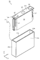
- FIG. 1 is a perspective view showing the appearance of a power storage device according to an embodiment.
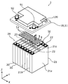
- FIG. 2 is an exploded perspective view showing a schematic configuration of the power storage device according to the embodiment.
- FIG. 3 is an exploded perspective view showing an overview of the configuration of the storage device according to the embodiment.
- FIG. 4 is a perspective view showing the configuration of the gas diffusion member and its surroundings according to the embodiment.
- FIG. 5 is a first cross-sectional view of the power storage device according to the embodiment.
- FIG. 6 is a second cross-sectional view of the power storage device according to the embodiment.
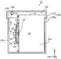
- FIG. 7 is a cross-sectional view of a power storage device according to Modification 1 of the embodiment.
- FIG. 8 is a cross-sectional view of a power storage device according to Modification 2 of the embodiment.
- FIG. 9 is a cross-sectional view of a power storage device according to Modification 3 of the embodiment.
- a power storage device includes: an exterior body; and a metal plate-like gas diffusion member arranged to face the gas discharge valves of the plurality of storage elements, wherein the gas diffusion member extends in the first direction.
- the gas ejected from the gas discharge valve collides with the gas diffusion member to disperse the pressure and lower the temperature.
- the gas diffusion member is arranged apart from other members (such as the lid of the exterior body) arranged on the first direction side of the plurality of power storage elements. Therefore, the heat of the gas diffusion member made of metal with high thermal conductivity is less likely to be transmitted to the other member. Therefore, the heat of the gas reduces the possibility that other members made of resin or the like will be weakened or melted.
- the gas ejected in the first direction and colliding with the gas diffusion member detours from at least both the second direction side and the third direction side of the gas diffusion member, It can spread in space on the direction side.
- the internal space of the exterior body can be widely used to diffuse the gas, and as a result, the pressure and temperature of the gas can be rapidly lowered.
- the power storage device of this aspect it is possible to suppress further deterioration of the state when an unsafe event occurs.
- the gas diffusion member may be formed with a plurality of through holes penetrating in the first direction.
- part of the gas that has collided with the gas diffusion member can penetrate the gas diffusion member. That is, since the flow direction of the gas that collides with the gas diffusion member increases, the pressure of the gas is efficiently dispersed, and the temperature of the gas is also efficiently lowered.
- the power storage device further includes a busbar holder that holds a busbar disposed on the first direction side of the plurality of power storage elements and electrically connected to the plurality of power storage elements, wherein the busbar holder supports the gas diffusion. It is also possible to have a supporting portion that supports the member while being separated from the plurality of power storage elements and the other member.
- the gas diffusion member can be supported by the busbar holder required for holding the busbar, etc., so there is no need to newly provide a dedicated member for arranging the gas diffusion member at a predetermined position.
- the exterior body has an exterior body body that houses the plurality of power storage elements, and a lid body that closes an opening of the exterior body body. It is also possible to have a supporting portion that supports the device in a suspended manner while being spaced apart from the other member.
- the gas diffusion member can be supported by the lid of the exterior body, so there is no need to newly provide a dedicated member for arranging the gas diffusion member at a predetermined position.
- the exterior body has an exhaust port for discharging the gas inside the exterior body to the outside, and the gas diffusion member is located between the gas exhaust valve and the exhaust port in the first direction. It may be arranged at a position.
- the gas ejected from the gas discharge valve in the first direction and diffused by the gas diffusion member is discharged from the opening located on the first direction side of the gas diffusion member to the outside of the exterior body. discharged to That is, the gas ejected from at least one gas exhaust valve and having its pressure (flow velocity) and temperature lowered by the gas diffusion member is efficiently exhausted to the outside of the exterior body.
- the direction in which a plurality of power storage elements are arranged is defined as the X-axis direction (except for Modification 3).
- the direction in which the electrode terminals of one storage element are arranged or the direction in which the short sides of the container of the storage element face each other is defined as the Y-axis direction (excluding Modifications 2 and 3).
- the direction in which the exterior main body and the lid are arranged in the exterior of the power storage device, or the vertical direction, is defined as the Z-axis direction.
- X-axis direction, Y-axis direction, and Z-axis direction are directions that intersect each other (hereinafter, orthogonally in the embodiment).
- the Z-axis direction may not be the vertical direction, but for convenience of explanation, the Z-axis direction will be described below as the vertical direction.
- expressions indicating relative directions or orientations such as parallel and orthogonal may be used, but strictly speaking, these expressions also include cases where the directions or orientations are not the same.
- two directions are parallel means not only that the two directions are completely parallel, but also substantially parallel, i.e., including a difference of about several percent also means
- the positive direction of the X-axis indicates the arrow direction of the X-axis
- the negative direction of the X-axis indicates the direction opposite to the positive direction of the X-axis.
- the Y-axis direction and the Z-axis direction The same applies to the Y-axis direction and the Z-axis direction.
- simply referring to the "X-axis direction” means either or both directions parallel to the X-axis. The same applies to terms relating to the Y-axis and Z-axis.
- FIG. 1 is a perspective view showing the appearance of a power storage device 1 according to an embodiment.
- FIG. 2 is an exploded perspective view showing a schematic configuration of the power storage device 1 according to the embodiment.
- FIG. 3 is an exploded perspective view showing a schematic configuration of the storage device 20 according to the embodiment.
- the power storage device 1 is a device that can charge electricity from the outside and discharge electricity to the outside, and has a substantially rectangular parallelepiped shape in the present embodiment.
- the power storage device 1 is a battery module (assembled battery) used for power storage or power supply.
- the power storage device 1 is, for example, an automobile, a motorcycle, a watercraft, a ship, a snowmobile, an agricultural machine, a construction machine, or a rolling stock for an electric railway. It is used as a battery etc.
- Examples of such vehicles include electric vehicles (EV), hybrid electric vehicles (HEV), plug-in hybrid electric vehicles (PHEV), and gasoline vehicles.
- Electric trains, monorails, and maglev trains are exemplified as railway vehicles for the electric railway.
- the power storage device 1 can also be used as a stationary battery or the like for home use or business use.
- the power storage device 1 includes a plurality of power storage elements 20 and an exterior body 10 that accommodates the plurality of power storage elements 20 .
- exterior body 10 accommodates eight power storage elements 20 .
- the number of power storage elements 20 included in power storage device 1 is not limited to eight.
- the power storage device 1 may include two or more power storage elements 20 .
- one storage element unit 28 is configured by a plurality of storage elements 20 arranged in the X-axis direction.
- the storage element unit 28 may have a spacer, an insulating film, and the like (not shown).
- the exterior body 10 has an exterior body body 12 that accommodates the power storage element unit 28 and a lid body 11 that closes an opening of the exterior body body 12 (body opening 15).
- a busbar holder 17 is arranged between the storage element unit 28 accommodated in the exterior body main body 12 and the lid body 11 .
- a plurality of busbars 33 are held in the busbar holder 17 .
- electrical devices such as a control circuit and a relay, electric wires, and the like may be arranged, but illustrations and descriptions thereof are omitted.
- the exterior body 10 is a rectangular (box-shaped) container (module case) that constitutes the outer shell of the power storage device 1 .
- the exterior body 10 is a member that fixes the electric storage element unit 28, the busbar holder 17, and the like at predetermined positions and protects them from impacts and the like.
- the exterior body 10 is made of, for example, polycarbonate (PC), polypropylene (PP), polyethylene (PE), polystyrene (PS), polyphenylene sulfide resin (PPS), polyphenylene ether (PPE (including modified PPE)), polyethylene terephthalate ( PET), polybutylene terephthalate (PBT), polyetheretherketone (PEEK), tetrafluoroethylene-perfluoroalkyl vinyl ether (PFA), polytetrafluoroethylene (PTFE), polyethersulfone (PES), ABS resin, or , an insulating member such as a composite material thereof, or a metal coated with an insulating coating.
- PC polycarbonate
- PP polypropylene
- PE polyethylene
- PS polystyrene
- PPS polyphenylene sulfide resin
- PPE polyphenylene ether
- PPE polyphenylene ether
- PET polyethylene terephthalate
- PBT poly
- the lid 11 of the exterior body 10 is a rectangular member that closes the body opening 15 of the exterior body 12 , and has a positive electrode side external terminal 91 and a negative electrode side external terminal 92 .
- the external terminals 91 and 92 are electrically connected to the plurality of power storage elements 20 via the busbars 33, and the power storage device 1 is charged with electricity from the outside via the external terminals 91 and 92, and Discharge electricity to the outside.
- the external terminals 91 and 92 are made of a conductive member made of metal such as aluminum or aluminum alloy.
- the exterior body 12 included in the exterior body 10 is a bottomed rectangular cylindrical housing in which a body opening 15 for accommodating the power storage element unit 28 is formed.
- the exterior body main body 12 has a pair of wall portions 14 facing each other in the X-axis direction and a pair of wall portions 13 facing each other in the Y-axis direction.
- a body opening 15 is formed by the upper ends of these four walls.
- the main body opening 15 and the lid 11 are joined without a gap by, for example, heat welding, bonding with an adhesive, or fastening with a gasket interposed.
- the storage element 20 is a secondary battery (single battery) capable of charging and discharging electricity, and more specifically, a non-aqueous electrolyte secondary battery such as a lithium ion secondary battery. .
- the storage element 20 may be a secondary battery other than a non-aqueous electrolyte secondary battery, or may be a capacitor.
- the storage element 20 may be a primary battery that allows the stored electricity to be used without being charged by the user.
- the storage element 20 may be a battery using a solid electrolyte.
- the storage element 20 may be a pouch-type storage element.
- the storage element 20 includes a flat rectangular parallelepiped (square) metal container 21 .
- the container 21 has a rectangular shape having a pair of long side surfaces 21a facing each other, a pair of short side surfaces 21b facing each other, and a terminal arrangement surface 21c connected to upper ends of the pair of long side surfaces 21a and the pair of short side surfaces 21b. is the case.
- the container 21 has a container body 25 and a cover plate 24 that closes the opening of the container body 25. 21a and a pair of short sides 21b are formed.
- the upper surface of the cover plate 24 forms a terminal arrangement surface 21c.
- the container main body 25 accommodates an electrode body 26, current collectors 27 on the positive electrode side and the negative electrode side, and an electrolytic solution (not shown).
- each of the plurality of power storage elements 20 is arranged in a row in the X-axis direction with the long side 21a facing the X-axis direction (the short side 21b is parallel to the X-axis direction).
- the electrode body 26 in the present embodiment is a wound electrode body formed by winding electrode plates (a positive electrode plate and a negative electrode plate) with separators interposed therebetween. Both ends of the electrode body 26 in the winding axis direction (Y-axis direction) are joined to leg portions of the current collector 27 .
- the electrode body provided in the storage element 20 is not limited to the wound type.
- the storage element 20 is provided with a laminated electrode body in which flat plate-shaped electrode plates are laminated, or an electrode body having a structure in which long strip-shaped electrode plates are laminated in a bellows shape by repeating mountain folds and valley folds.
- the posture of the electrode body does not need to be such that the winding axis direction is parallel to the Y-axis direction (the direction in which the pair of short side surfaces 21b face each other).
- the electrode body may be provided on the storage element 20 in a posture in which the winding axis direction is parallel to the Z-axis direction (longitudinal direction of the short side surface 21b).
- Metal electrode terminals 22 (a positive electrode terminal and a negative electrode terminal) electrically connected to the electrode body 26 inside the container body 25 via the current collector 27 are arranged on the terminal arrangement surface 21c of the cover plate 24. ing.
- the electrode terminal 22 is fixed to the cover plate 24 via a resin gasket (not shown), for example.
- a lid plate 24 of the container 21 is further provided with a gas discharge valve 23 for discharging the gas inside the container 21 to the outside. For example, when the internal pressure of the container 21 rises due to the vaporization of the electrolytic solution inside the container 21, the gas discharge valve 23 is opened (opened) to discharge the gas inside the container 21 to the outside of the container 21.
- the gas discharge valve 23 of each of the plurality of power storage elements 20 is oriented in the Z-axis plus direction, which is an example of the first direction.
- the X-axis direction which is the direction in which the plurality of storage elements 20 are arranged, is an example of a second direction that intersects the first direction
- the Y-axis direction is an example of a third direction that intersects the first direction and the second direction. be.
- the rectangular parallelepiped (square) power storage element 20 is illustrated, but the shape of the power storage element 20 is not limited to the rectangular parallelepiped shape, and may be a polygonal prism shape or the like other than the rectangular parallelepiped shape. .
- the busbar 33 is a rectangular plate-shaped member that is placed on at least two storage elements 20 while being held by the busbar holder 17 and electrically connects the electrode terminals 22 of the at least two storage elements 20 .
- the material of the bus bar 33 is not particularly limited, and may be formed of, for example, a metal such as aluminum, an aluminum alloy, copper, a copper alloy, a combination thereof, or a conductive member other than metal.
- five bus bars 33 are used to connect the energy storage elements 20 two by two in parallel to form four groups of energy storage elements 20, and the four groups of energy storage elements 20 are connected in series. Connected.
- the manner of electrical connection of the eight storage elements 20 is not particularly limited, and for example, all the eight storage elements 20 may be connected in series.
- the busbar holder 17 is a resin member that holds the busbar 33 .
- As the resin material for forming the busbar holder 17, PC, PP, PE, PS, PPS, or the like is adopted as in the exterior body 10.
- FIG. In this embodiment, the busbar holder 17 also serves to support the gas diffusion member 50, which will be described later.
- the busbar holder 17 is provided with a plurality of busbar openings 17 a that hold the plurality of busbars 33 and expose a portion of each of the plurality of busbars 33 toward the plurality of power storage elements 20 .
- the busbar holder 17 is further provided with an elongated exhaust opening 18 in the direction in which the plurality of storage elements 20 are arranged.
- the exhaust opening 18 is arranged in the power storage element unit 28 at a position facing the plurality of gas exhaust valves 23 arranged in the alignment direction. The gas discharged from these gas discharge valves 23 can pass through the busbar holder 17 in the Z-axis plus direction via the discharge opening 18 .
- a gas diffusion member 50 for diffusing the gas ejected from the gas discharge valves 23 when the gas discharge valves 23 are opened is provided at a position facing the plurality of gas discharge valves 23 .
- a plurality of support portions 19 are arranged around the exhaust opening 18 in the busbar holder 17, and the gas diffusion member 50 is supported by the plurality of support portions 19. there is thereby, the gas diffusion member 50 is arranged at a position separated from both the storage element unit 28 and the lid 11 in the Z-axis direction. That is, the gas traveling in the positive direction of the Z axis through the exhaust opening 18 is diffused in various directions by the gas diffusion member 50 disposed ahead.
- FIG. 4 is a perspective view showing the configuration of the gas diffusion member 50 and its surroundings according to the embodiment.
- FIG. 4 only the lid 11, the gas diffusion member 50, and the electric storage element unit 28 are illustrated, and each of them is illustrated separated in the Z-axis direction.
- Each of the hollow arrows and dotted arrows illustrated in FIG. 4 and subsequent figures schematically indicates the flow of the gas.
- FIG. 5 is a first cross-sectional view of power storage device 1 according to the embodiment
- FIG. 6 is a second cross-sectional view of power storage device 1 according to the embodiment.
- FIG. 5 simply illustrates a cross section of the power storage device 1 in the YZ plane passing through the IV-IV line in FIG.
- FIG. 5 simply illustrates a cross section of the power storage device 1 in the YZ plane passing through the IV-IV line in FIG.
- FIG. 6 simply illustrates a cross section of the power storage device 1 on the XZ plane passing through the VV line in FIG. 5 and 6 show the external shape of the storage element 20 when viewed from the X-axis direction or the Y-axis direction, and the approximate existence range of the gas discharge valve 23 is represented by a hatched rectangle. ing.
- the power storage device 1 includes a gas diffusion member 50 at a position facing the power storage element unit 28 having a plurality of power storage elements 20 .
- the gas diffusion members 50 are plate-shaped members made of metal, and are arranged side by side in the X-axis direction when viewed from the Z-axis positive direction (planar view) with the thickness direction facing the power storage element unit 28 . It is arranged at a position covering the plurality of gas discharge valves 23 .
- Metals forming the gas diffusion member 50 include iron, stainless steel, aluminum, and aluminum alloys. Therefore, the gas diffusion member 50 is not melted by the high-temperature (for example, about 400°) gas ejected from the gas discharge valve 23 when the valve is opened.
- the size and shape of the gas diffusion member 50 in plan view cover the plurality of gas discharge valves 23 and cover the storage element units 28 in the X-axis direction and the Y-axis direction. It has a size and shape that partially exposes.
- the gas diffusion member 50 is a rectangular member in plan view, but the shape in plan view may be a polygonal shape other than a rectangle, an elliptical shape, an oval shape, or the like.
- the position of the gas diffusion member 50 in the Z-axis direction is, as shown in FIGS. It is a position spaced apart from both.
- the power storage device 1 is housed in the exterior body 10 and the exterior body 10, each of which faces the first direction (Z-axis plus direction) with the gas discharge valve 23 facing in the second direction (X and a gas diffusion member 50 .
- the gas diffusion member 50 is a plate-like member made of metal arranged to face the gas discharge valves 23 of the plurality of power storage elements 20 .
- the gas diffusion member 50 is positioned between the plurality of storage elements 20 and the lid 11 , which is another member arranged at a position facing the plurality of storage elements 20 in the first direction, and is located between the plurality of storage elements 20 . 20 and lid body 11, respectively.
- the gas diffusion member 50 extends in the first direction both on the side of the gas diffusion member 50 in the second direction and on the side in the third direction (Y-axis direction) intersecting the first direction and the second direction. It is shaped and sized to allow the passage of gas.
- the gas ejected from the gas discharge valve 23 of the power storage element 20 collides with the gas diffusion member 50 to disperse the pressure. and its temperature drops.
- the gas diffusion member 50 is arranged apart from other members (cover 11 in the present embodiment) arranged on the first direction side of the plurality of power storage elements 20 . Therefore, the heat of the gas diffusion member 50 made of metal with high thermal conductivity is less likely to be transmitted to the lid body 11 . Therefore, the heat of the gas reduces the possibility that the strength of the lid 11 made of resin or the like is reduced or melted.
- the gas ejected in the first direction and colliding with the gas diffusion member 50 detours from at least the sides of the gas diffusion member 50 (both sides of the second direction and the third direction), and the gas diffuses. It can spread in the space on the first direction side of the member 50 . That is, the gas diffusion member 50 is not arranged so as to partition (partition) the space inside the exterior body 10 .
- the gas diffusion member 50 is formed in a shape and size that forms a space serving as a gas flow path on its side so that the gas that collides with the gas diffusion member 50 spreads over the gas diffusion member 50 .
- the internal space of the exterior body 10 can be widely used to diffuse the gas, and as a result, the pressure and temperature of the gas can be rapidly lowered.
- power storage device 1 of the present embodiment it is possible to suppress further deterioration of the state when an unsafe event occurs.
- the distance between the storage element 20 (more specifically, the gas discharge valve 23) and the gas diffusion member 50 in the first direction is set to suppress interference between the gas discharge valve 23 and the gas diffusion member 50 when the valve is open. , is preferably larger than half of the maximum outer dimension of the gas discharge valve 23 in plan view (the radius in the case of a circle). More preferably, the distance is larger than the maximum outer dimension (diameter in the case of a circle) of the gas exhaust valve 23 .
- the distance between the gas diffusion member 50 and another member (lid 11) in the first direction is preferably, for example, 1 mm or more in order to suppress heat conduction from the gas diffusion member 50 to the lid 11. More preferably, it is 5 mm or more.
- the temperature sensor may be arranged in contact with the gas diffusion member 50 .
- the gas diffusion member 50 which is made of metal and has high thermal conductivity, can be used to quickly detect a temperature rise when the valve is opened.
- the arrangement position of the gas diffusion member 50 is preferably the central portion of the gas diffusion member 50 in plan view.
- the gas diffusion member 50 is configured so that part of the gas that collides with the gas diffusion member 50 penetrates in the collision direction. Specifically, the gas diffusion member 50 is formed with a plurality of through holes 51 penetrating in the first direction. That is, as shown in FIGS. 4 to 6, the plate-like gas diffusion member 50 has a plurality of through-holes 51 penetrating in its thickness direction.
- the gas that has collided with the gas diffusion member 50 not only detours around the side of the gas diffusion member 50 and crosses the gas diffusion member 50, but also passes through the gas diffusion member 50 in the collision direction.
- the gas diffusion member 50 can be crossed by penetrating the diffusion member 50 . Since the gas diffusion member 50 is spaced apart from the lid 11 which is another member located directly above it, the gas that has passed over the gas diffusion member 50 is at least transmitted through the gas diffusion member 50 and the lid 11 .
- the plurality of through-holes 51 allow the gas diffusion member 50 to release pressure from the gas ejected from the gas discharge valve 23 , thereby suppressing deformation or damage of the gas diffusion member 50 due to the pressure of the gas. Therefore, for example, a relatively thin (low-rigidity) metal plate can be used as the base material of the gas diffusion member 50 , thereby reducing the weight of the power storage device 1 .
- the shape and size of the through hole 51 are not limited to a specific shape and size.
- Each of the plurality of through-holes 51 may be, for example, a circular hole with an inner diameter of about 1 to 5 mm, or a hole of any shape with a maximum inner dimension of 1 mm or less.
- the shape and size of the plurality of through holes 51 may not be uniform, and at least one of the shape and size may be random.
- the gas diffusion member 50 having a plurality of through-holes 51 does not need to be a plate-like metal plate with a plurality of through-holes 51 arranged in a matrix as shown in FIGS.
- a plate-shaped metal net or steel wool may be employed as the gas diffusion member 50 having a plurality of through-holes 51 .
- the power storage device 1 includes a busbar holder 17 that holds a busbar 33 that is arranged on the first direction side of the plurality of power storage elements 20 and electrically connected to the plurality of power storage elements 20 .
- the busbar holder 17 has a support portion 19 that supports the gas diffusion member 50 while being separated from the plurality of power storage elements 20 and the lid body 11 . More specifically, the busbar holder 17 has four support portions 19 distributed around the exhaust opening 18, and these four support portions 19 support the gas diffusion member 50 at four points. Support.
- the gas diffusion member 50 can be supported by the busbar holder 17 required for holding the busbar 33, etc., a dedicated member for arranging the gas diffusion member 50 at a predetermined position is newly provided. No need.
- the member having the support portion 19 that supports the gas diffusion member 50 while being separated from the gas discharge valve 23 and the lid body 11 is not limited to the busbar holder 17 .
- the support 19 may be provided in a tray or case that holds electrical equipment such as control circuits and relays.
- each of one or more rod-shaped (or string-shaped) members that connect the inner surface of the exterior main body 12 and the gas diffusion member 50 in the lateral direction (direction parallel to the XY plane) is the gas diffusion member 50.
- the supporting portion that supports the gas diffusion member 50 may be implemented by a member dedicated to supporting the gas diffusion member 50 .
- the exterior body 10 has an exhaust port 121 for discharging the gas inside the exterior body 10 to the outside.
- the gas diffusion member 50 is arranged at a position between the gas exhaust valve 23 and the exhaust port 121 in the first direction.
- a discharge port 121 is provided inside the cover 11 of the exterior body 10 .
- the exhaust port 121 is formed at a position communicating with an exhaust pipe 120 protruding from the outer surface of the lid 11 . That is, the gas that has flowed into the exhaust port 121 from the interior of the exterior body 10 passes through the exhaust pipe 120 and is discharged to the exterior of the exterior body 10 .
- the gas ejected in the first direction from the gas discharge valve 23 and diffused by the gas diffusion member 50 is discharged from the discharge port 121 positioned further in the first direction than the gas diffusion member 50, It is discharged to the outside of the exterior body 10 . That is, the gas ejected from at least one gas exhaust valve 23 and having its pressure (flow velocity) and temperature lowered by the gas diffusion member 50 is efficiently exhausted to the outside of the exterior body 10 .
- the power storage device 1 has been described above. good. Therefore, various modifications of the gas diffusion member 50 and its peripheral configuration will be described with reference to FIGS. 7 to 9, focusing on differences from the above embodiment.
- FIG. 7 is a cross-sectional view of a power storage device 1a according to Modification 1 of the embodiment. Supplementary matters such as the position of the cross section in FIG. 7 and the simplified illustration of the cross section conform to FIG. 5 described above. This also applies to FIGS. 8 and 9, which will be described later.
- the power storage device 1a according to this modification includes a gas diffusion member 50 made of metal and having a plate shape.
- the gas diffusion member 50 is arranged at a position between the lid body 11a and the plurality of power storage elements 20 and separated from the plurality of power storage elements 20 and the lid body 11a. These configurations are common to the power storage device 1 according to the embodiment.
- the power storage device 1a according to this modification differs from the power storage device 1 according to the embodiment in that the gas diffusion member 50 is supported by the support portion 19a provided on the lid 11a.
- the exterior body 10a has an exterior body main body 12a that accommodates a plurality of power storage elements 20 and a lid body 11a that closes the main body opening 15 .
- the lid body 11a has a support portion 19a that supports the gas diffusion member 50 in a suspended manner while being separated from the plurality of storage elements 20 and the lid body 11a, which is another member.
- the gas diffusion member 50 can be supported by the lid 11a of the exterior body 10, so there is no need to newly provide a dedicated member for arranging the gas diffusion member 50 at a predetermined position.
- each of one or more rod-shaped (or string-shaped) members connecting the inner surface of the lid 11a and the gas diffusion member 50 in the lateral direction separates the gas diffusion member 50 from the gas discharge valve 23 and the lid 11a.
- FIG. 8 is a cross-sectional view of a power storage device 1b according to Modification 2 of the embodiment.
- a power storage device 1b according to this modification includes a power storage element unit 28 having a plurality of power storage elements 20 arranged in the X-axis direction, and an exterior body 10b that accommodates the power storage element unit 28.
- the exterior body 10b has an exterior body main body 12b and a lid body 11b.
- the plurality of power storage elements 20 and the wall portion 13b (of the exterior main body 12b), which is another member are positioned facing the gas discharge valves 23 of the power storage elements 20.
- a plate-shaped gas diffusion member 50 made of metal is arranged between the wall portion 13b).
- the gas diffusion member 50 is arranged at a position separated from each of the plurality of power storage elements 20 and the wall portion 13b. Spaces in which gas can move are formed in the vertical direction (Z-axis direction) and sideways (directions parallel to the XY plane) of the gas diffusion member 50 .
- the power storage device 1b according to this modification has a configuration common to that of the power storage device 1 according to the embodiment.
- the power storage device 1b according to the present modification differs from the power storage device 1 according to the embodiment in that each of the plurality of power storage elements 20 is arranged with the gas discharge valve 23 directed in the positive direction of the Y axis. different. More specifically, the plurality of power storage elements 20 are arranged in the X-axis direction with the gas discharge valve 23 directed in the Y-axis plus direction and the long side surface 21a directed in the X-axis direction.
- the description of the configuration is as follows. This is common with the description of the configuration of the power storage device 1 according to the embodiment. That is, the power storage device 1b is housed in the exterior body 10b and the exterior body 10b, each of which has a posture in which the gas discharge valve 23 is directed in the first direction (Y-axis plus direction), and in the second direction intersecting the first direction. It includes a plurality of power storage elements 20 arranged in the (X-axis direction) and a gas diffusion member 50 .
- the gas diffusion member 50 is positioned between the plurality of storage elements 20 and the wall portion 13b arranged at a position facing the plurality of storage elements 20 in the first direction, and is located between the plurality of storage elements 20 and the wall portion 13b. are arranged at positions separated from each other.
- the gas diffusion member 50 extends in the first direction both on the side of the gas diffusion member 50 in the second direction and on the side in the third direction (Z-axis direction) intersecting the first direction and the second direction. It is shaped and sized to allow the passage of gas.
- the pressure and temperature of the gas ejected from the gas discharge valve 23 can be quickly reduced by the gas diffusion member 50, as in the power storage device 1 according to the embodiment. can be done. This suppresses deterioration in strength, melting, or the like of the exterior body 10b. Therefore, according to the power storage device 1b, it is possible to suppress further deterioration of the state when an unsafe event occurs.
- FIG. 9 is a cross-sectional view of a power storage device 1c according to Modification 3 of the embodiment.
- a power storage device 1c according to this modification includes a power storage element unit 28 having a plurality of power storage elements 20 arranged in the Z-axis direction, and an exterior body 10c that accommodates the power storage element unit 28.
- the exterior body 10c has an exterior body main body 12c and a lid body 11c.
- the plurality of power storage elements 20 and the wall portion 13c (of the exterior main body 12c), which is another member, are located opposite the gas discharge valves 23 of the power storage elements 20.
- a plate-like gas diffusion member 50 made of metal is arranged between the wall portion 13c).
- the gas diffusion member 50 is arranged at a position separated from each of the plurality of power storage elements 20 and the wall portion 13c. Spaces in which gas can move are formed in the vertical direction (Z-axis direction) and sideways (directions parallel to the XY plane) of the gas diffusion member 50 .
- the power storage device 1c according to this modification has a configuration common to that of the power storage device 1 according to the embodiment.
- the power storage device 1c according to the present modification differs from the power storage device 1 according to the embodiment in that each of the plurality of power storage elements 20 is arranged with the gas discharge valve 23 directed in the positive direction of the Y axis. different. More specifically, the plurality of power storage elements 20 are arranged in the Z-axis direction with the gas discharge valve 23 directed in the Y-axis positive direction and the short side surface 21b directed in the X-axis direction. That is, in this modified example, the plurality of power storage elements 20 are stacked vertically.
- the description of the configuration is as follows. This is common with the description of the configuration of the power storage device 1 according to the embodiment. That is, the power storage device 1c is housed in the exterior body 10c and the exterior body 10c, each of which is in a posture in which the gas discharge valve 23 is directed in the first direction (Y-axis plus direction), and in the second direction intersecting the first direction. It includes a plurality of power storage elements 20 arranged in the (Z-axis direction) and a gas diffusion member 50 .
- the gas diffusion member 50 is positioned between the plurality of storage elements 20 and the wall portion 13b arranged at a position facing the plurality of storage elements 20 in the first direction, and is located between the plurality of storage elements 20 and the wall portion 13b. are arranged at positions separated from each other.
- the gas diffusion member 50 extends in the first direction both on the side of the gas diffusion member 50 in the second direction and on the side in the third direction (X-axis direction) intersecting the first direction and the second direction. It is shaped and sized to allow the passage of gas.
- the gas diffusion member 50 quickly reduces the pressure and temperature of the gas ejected from the gas discharge valve 23, as in the power storage device 1 according to the embodiment. be able to. This suppresses deterioration in strength, melting, or the like of the exterior body 10c. Therefore, according to the power storage device 1c, it is possible to suppress further deterioration of the state when an unsafe event occurs.
- other members arranged in the first direction which is the direction in which the gas discharge valve 23 is directed with respect to the electric storage element 20 , need not be part of the exterior body 10 .
- a control device or an electric device such as a relay, or a tray or the like for holding the electric device is arranged at a position facing the gas discharge valve 23 in the first direction
- another member such as a tray or an electric device, is arranged. and the storage element 20, the gas diffusion member 50 is arranged.
- the gas diffusion member 50 is arranged.
- the gas diffusion member 50 when a member formed of a material (resin or the like) having a lower melting point than the gas diffusion member 50 is arranged as another member, the gas diffusion member 50 is arranged apart from the other member. , the other member can be protected from the gas while obtaining the effect of lowering the pressure and temperature of the gas by the gas diffusion member 50 . That is, for example, in the structures shown in FIGS. 4 to 6, even if an electrical device is placed between the gas diffusion member 50 and the lid 11, the electrical device can be , from the gas ejected from the gas discharge valve 23 . Furthermore, the gas diffusion member 50 can widely utilize the internal space of the exterior body 10 to diffuse the gas, and as a result, the pressure and temperature of the gas are efficiently lowered.
- the gas diffusion member 50 does not need to have a shape and size that collectively cover the plurality of gas discharge valves 23 in plan view.
- a separate gas diffusion member may be arranged for each of the plurality of gas discharge valves 23 . Even in this case, if spaces through which the gas can pass are formed in the upper, lower, left, and right sides of the gas diffusion member, the internal space of the exterior body 10 can be widely used to diffuse the gas.
- the gas diffusion member 50 does not need to be supported by a member other than the electric storage element 20, such as the busbar holder 17, and may be supported by the electric storage element 20. For example, by fixing one or more legs extending from the gas diffusion member 50 toward the storage element unit 28 to the terminal arrangement surface 21c (see FIG. 3) of the one or more storage elements 20 with an adhesive or the like. , the gas diffusion member 50 may be arranged with respect to the electric storage element unit 28 . As described above, when an individual gas diffusion member is arranged for each of the multiple gas discharge valves 23, each of the multiple storage elements 20 may support the gas diffusion member corresponding to the storage element 20. .
- a form constructed by arbitrarily combining the plurality of components described above is also included within the scope of the present invention.
- various supplementary matters regarding power storage device 1 according to the above-described embodiment may be applied to any one of power storage devices 1a to 1c according to modified examples 1 to 3.
- the present invention can be applied to a power storage device having a power storage element such as a lithium ion secondary battery.
Abstract
This power storage device is equipped with: an outer body; a plurality of power storage elements which are arranged in a second direction perpendicular to a first direction in an orientation in which the gas discharge valve of each faces the first direction; and a gas diffusion member. The gas diffusion member is a metal plate-shaped member positioned so as to face the gas discharge valves of the plurality of power storage elements. The gas diffusion member is positioned: in a location between the plurality of power storage elements and a lid, which is another member positioned in a location facing the plurality of power storage elements in the first direction; and in a location which is separated from each of the plurality of power storage elements and from the lid. The gas diffusion member is formed in a shape and size which permit the passage of a gas in the first direction both to the side of the gas diffusion member in the second direction and to the side of the gas diffusion member in a third direction which intersects the first and second directions.
Description
本発明は、複数の蓄電素子と、複数の蓄電素子を収容する外装体とを備える蓄電装置に関する。
The present invention relates to a power storage device that includes a plurality of power storage elements and an exterior body that accommodates the plurality of power storage elements.
特許文献1には、複数のセル(蓄電素子)を有する電池スタックと、電池スタックを収容するケース(外装体)とを備える電池パック(蓄電装置)が開示されている。この蓄電装置において、各蓄電素子は、内圧が上昇した場合に内部のガスを外部に排出するように構成されたガス排出弁を有する。外装体における蓋体であるアッパーケースの内面には、平面視において各ガス排出弁と重なる位置に、金属製の板材がボルト等の固定具によって取り付けられている。これにより、ガス排出弁から勢いよく排出される高温のガスが、蓋体に直接突き当たることが防止される。
Patent Document 1 discloses a battery pack (power storage device) that includes a battery stack having a plurality of cells (power storage elements) and a case (enclosure) that houses the battery stack. In this power storage device, each power storage element has a gas discharge valve configured to discharge internal gas to the outside when the internal pressure increases. A metal plate member is attached to the inner surface of the upper case, which is the lid member of the exterior body, by means of fasteners such as bolts, at a position overlapping each gas discharge valve in a plan view. This prevents the high-temperature gas that is vigorously discharged from the gas discharge valve from hitting the lid directly.
上記従来の蓄電装置では、例えば、ガスの熱が金属製の板材を介して樹脂製の蓋体に伝わりやすいため、この熱によって、蓋体における板材が固定された部分の強度低下または溶融等が生じる可能性がある。外装体の一部に強度低下または溶融等が生じた場合、外装体の予期せぬ位置からのガスの流出、または、ガスの内圧による外装体の破壊等が生じる場合がある。つまり、蓄電装置の状態がさらに悪化する可能性がある。
In the above-described conventional power storage device, for example, the heat of the gas is easily transmitted to the resin lid via the metal plate. may occur. When a portion of the exterior body is weakened or melted, gas may flow out from an unexpected position of the exterior body, or the exterior body may be destroyed due to the internal pressure of the gas. In other words, the state of the power storage device may further deteriorate.
本発明は、本願発明者が上記課題に新たに着目することによってなされたものであり、不安全事象が生じた場合における状態の更なる悪化を抑制することができる蓄電装置を提供することを目的とする。
SUMMARY OF THE INVENTION The present invention was made by the inventors of the present invention by newly paying attention to the above problem, and an object of the present invention is to provide a power storage device capable of suppressing further deterioration of the state when an unsafe event occurs. and
本発明の一態様に係る蓄電装置は、外装体と、前記外装体に収容され、それぞれが第一方向にガス排出弁を向けた姿勢で、前記第一方向と交差する第二方向に並べられた複数の蓄電素子と、前記複数の蓄電素子の前記ガス排出弁に対向して配置された、金属製かつ板状のガス拡散部材とを備え、前記ガス拡散部材は、前記第一方向において前記複数の蓄電素子に対向する位置に配置された他の部材と、前記複数の蓄電素子との間の位置であって、前記複数の蓄電素子及び前記他の部材のそれぞれと離間した位置に配置され、かつ、前記ガス拡散部材の、前記第二方向の側方、及び、前記第一方向及び前記第二方向に交差する第三方向の側方の両方において、前記第一方向へのガスの通過を許容する形状及びサイズに形成されている。
A power storage device according to an aspect of the present invention includes: an exterior body; and a metal plate-like gas diffusion member arranged to face the gas discharge valves of the plurality of storage elements, wherein the gas diffusion member extends in the first direction. A position between another member arranged at a position facing the plurality of power storage elements and the plurality of power storage elements and a position spaced apart from each of the plurality of power storage elements and the other member and the passage of gas in the first direction on both sides of the gas diffusion member in the second direction and in a third direction crossing the first direction and the second direction. It is shaped and sized to allow
本発明に係る蓄電装置によれば、不安全事象が生じた場合における状態の更なる悪化を抑制することができる。
According to the power storage device of the present invention, it is possible to suppress further deterioration of the state when an unsafe event occurs.
本発明の一態様に係る蓄電装置は、外装体と、前記外装体に収容され、それぞれが第一方向にガス排出弁を向けた姿勢で、前記第一方向と交差する第二方向に並べられた複数の蓄電素子と、前記複数の蓄電素子の前記ガス排出弁に対向して配置された、金属製かつ板状のガス拡散部材とを備え、前記ガス拡散部材は、前記第一方向において前記複数の蓄電素子に対向する位置に配置された他の部材と、前記複数の蓄電素子との間の位置であって、前記複数の蓄電素子及び前記他の部材のそれぞれと離間した位置に配置され、かつ、前記ガス拡散部材の、前記第二方向の側方、及び、前記第一方向及び前記第二方向に交差する第三方向の側方の両方において、前記第一方向へのガスの通過を許容する形状及びサイズに形成されている。
A power storage device according to an aspect of the present invention includes: an exterior body; and a metal plate-like gas diffusion member arranged to face the gas discharge valves of the plurality of storage elements, wherein the gas diffusion member extends in the first direction. A position between another member arranged at a position facing the plurality of power storage elements and the plurality of power storage elements and a position spaced apart from each of the plurality of power storage elements and the other member and the passage of gas in the first direction on both sides of the gas diffusion member in the second direction and in a third direction crossing the first direction and the second direction. It is shaped and sized to allow
この構成によれば、例えば1つの蓄電素子が開弁した場合、ガス排出弁から噴出するガスは、ガス拡散部材に衝突することで圧力が分散され、かつ、その温度は低下する。また、ガス拡散部材は、複数の蓄電素子の第一方向側に配置された他の部材(外装体の蓋体等)とは離間して配置されている。そのため、熱伝導性が高い金属で形成されたガス拡散部材の熱が当該他の部材に伝わり難い。従って、ガスの熱によって、樹脂等で形成された他の部材の強度低下または溶融等の可能性が低減される。さらに、第一方向に向けて噴出してガス拡散部材に衝突したガスは、少なくとも、ガス拡散部材の、第二方向側及び第三方向側の両側から迂回して、ガス拡散部材よりも第一方向側の空間に広がることができる。これにより、例えば、外装体の内部空間を広く利用してガスを拡散させることができ、その結果、ガスの圧力と温度とを迅速に低下させることができる。このように、本態様に係る蓄電装置によれば、不安全事象が生じた場合における状態の更なる悪化を抑制することができる。
According to this configuration, for example, when one electric storage element opens, the gas ejected from the gas discharge valve collides with the gas diffusion member to disperse the pressure and lower the temperature. In addition, the gas diffusion member is arranged apart from other members (such as the lid of the exterior body) arranged on the first direction side of the plurality of power storage elements. Therefore, the heat of the gas diffusion member made of metal with high thermal conductivity is less likely to be transmitted to the other member. Therefore, the heat of the gas reduces the possibility that other members made of resin or the like will be weakened or melted. Further, the gas ejected in the first direction and colliding with the gas diffusion member detours from at least both the second direction side and the third direction side of the gas diffusion member, It can spread in space on the direction side. Thereby, for example, the internal space of the exterior body can be widely used to diffuse the gas, and as a result, the pressure and temperature of the gas can be rapidly lowered. As described above, according to the power storage device of this aspect, it is possible to suppress further deterioration of the state when an unsafe event occurs.
前記ガス拡散部材には、前記第一方向に貫通する複数の貫通孔が形成されている、としてもよい。
The gas diffusion member may be formed with a plurality of through holes penetrating in the first direction.
この構成によれば、ガス拡散部材に衝突したガスの一部はガス拡散部材を貫通することができる。つまり、ガス拡散部材に衝突したガスの流通方向が増えるため、ガスの圧力が効率よく分散され、かつ、ガスの温度も効率よく低下される。
According to this configuration, part of the gas that has collided with the gas diffusion member can penetrate the gas diffusion member. That is, since the flow direction of the gas that collides with the gas diffusion member increases, the pressure of the gas is efficiently dispersed, and the temperature of the gas is also efficiently lowered.
前記蓄電装置はさらに、前記複数の蓄電素子の前記第一方向側に配置され、前記複数の蓄電素子に電気的に接続されたバスバーを保持するバスバーホルダを備え、前記バスバーホルダは、前記ガス拡散部材を、前記複数の蓄電素子及び前記他の部材と離間した状態で支持する支持部を有する、としてもよい。
The power storage device further includes a busbar holder that holds a busbar disposed on the first direction side of the plurality of power storage elements and electrically connected to the plurality of power storage elements, wherein the busbar holder supports the gas diffusion. It is also possible to have a supporting portion that supports the member while being separated from the plurality of power storage elements and the other member.
この構成によれば、バスバーの保持等に必要なバスバーホルダにガス拡散部材を支持させることができるため、ガス拡散部材を所定の位置に配置するための専用の部材を新たに備える必要がない。
According to this configuration, the gas diffusion member can be supported by the busbar holder required for holding the busbar, etc., so there is no need to newly provide a dedicated member for arranging the gas diffusion member at a predetermined position.
前記外装体は、前記複数の蓄電素子を収容する外装体本体と、前記外装体本体の開口を塞ぐ蓋体とを有し、前記蓋体は、前記ガス拡散部材を、前記複数の蓄電素子及び前記他の部材と離間した状態で吊り下げ状に支持する支持部を有する、としてもよい。
The exterior body has an exterior body body that houses the plurality of power storage elements, and a lid body that closes an opening of the exterior body body. It is also possible to have a supporting portion that supports the device in a suspended manner while being spaced apart from the other member.
この構成によれば、外装体の蓋体にガス拡散部材を支持させることができるため、ガス拡散部材を所定の位置に配置するための専用の部材を新たに備える必要がない。
According to this configuration, the gas diffusion member can be supported by the lid of the exterior body, so there is no need to newly provide a dedicated member for arranging the gas diffusion member at a predetermined position.
前記外装体は、前記外装体の内部の前記ガスを外部に排出するための排出口を有し、前記ガス拡散部材は、前記第一方向において、前記ガス排出弁と前記排出口との間の位置に配置されている、としてもよい。
The exterior body has an exhaust port for discharging the gas inside the exterior body to the outside, and the gas diffusion member is located between the gas exhaust valve and the exhaust port in the first direction. It may be arranged at a position.
この構成によれば、ガス排出弁から第一方向に向けて噴出し、ガス拡散部材によって拡散されたガスは、ガス拡散部材よりも更に第一方向側に位置する開口部から、外装体の外部に排出される。つまり、少なくとも1つのガス排出弁から噴出し、ガス拡散部材によって圧力(流速)及び温度が低下されたガスは、効率よく、外装体の外部に排出される。
According to this configuration, the gas ejected from the gas discharge valve in the first direction and diffused by the gas diffusion member is discharged from the opening located on the first direction side of the gas diffusion member to the outside of the exterior body. discharged to That is, the gas ejected from at least one gas exhaust valve and having its pressure (flow velocity) and temperature lowered by the gas diffusion member is efficiently exhausted to the outside of the exterior body.
以下、図面を参照しながら、本発明の実施の形態(変形例も含む)に係る蓄電装置について説明する。以下で説明する実施の形態は、いずれも包括的または具体的な例を示すものである。以下の実施の形態で示される数値、形状、材料、構成要素、構成要素の配置位置及び接続形態などは、一例であり、本発明を限定する主旨ではない。各図において、寸法等は厳密に図示したものではない。
Power storage devices according to embodiments (including modifications) of the present invention will be described below with reference to the drawings. All of the embodiments described below are generic or specific examples. Numerical values, shapes, materials, constituent elements, arrangement positions of constituent elements, connection forms, and the like shown in the following embodiments are examples, and are not intended to limit the present invention. In each drawing, dimensions and the like are not strictly illustrated.
以下の説明及び図面中において、複数の蓄電素子の並び方向、蓄電素子の容器の長側面の対向方向、または、当該容器の厚さ方向をX軸方向と定義する(変形例3を除く)。1つの蓄電素子における電極端子の並び方向、または、蓄電素子の容器の短側面の対向方向をY軸方向と定義する(変形例2及び3を除く)。蓄電装置の外装体における外装体本体と蓋体との並び方向、または、上下方向をZ軸方向と定義する。これらX軸方向、Y軸方向及びZ軸方向は、互いに交差(以下実施の形態では、直交)する方向である。使用態様によってはZ軸方向が上下方向にならない場合も考えられるが、以下では説明の便宜のため、Z軸方向を上下方向として説明する。
In the following description and drawings, the direction in which a plurality of power storage elements are arranged, the direction in which the long sides of the container of the power storage elements face each other, or the thickness direction of the container is defined as the X-axis direction (except for Modification 3). The direction in which the electrode terminals of one storage element are arranged or the direction in which the short sides of the container of the storage element face each other is defined as the Y-axis direction (excluding Modifications 2 and 3). The direction in which the exterior main body and the lid are arranged in the exterior of the power storage device, or the vertical direction, is defined as the Z-axis direction. These X-axis direction, Y-axis direction, and Z-axis direction are directions that intersect each other (hereinafter, orthogonally in the embodiment). Depending on the mode of use, the Z-axis direction may not be the vertical direction, but for convenience of explanation, the Z-axis direction will be described below as the vertical direction.
以下の実施の形態において、平行及び直交などの、相対的な方向または姿勢を示す表現が用いられる場合があるが、これらの表現は、厳密には、その方向または姿勢ではない場合も含む。例えば、2つの方向が平行である、とは、当該2つの方向が完全に平行であることを意味するだけでなく、実質的に平行であること、すなわち、例えば数%程度の差異を含むことも意味する。以下の説明において、例えば、X軸プラス方向とは、X軸の矢印方向を示し、X軸マイナス方向とは、X軸プラス方向とは反対の方向を示す。Y軸方向及びZ軸方向についても同様である。さらに、単に、「X軸方向」という場合は、X軸に平行な双方向またはいずれか一方の方向を意味する。Y軸及びZ軸に関する用語についても同様である。
In the following embodiments, expressions indicating relative directions or orientations such as parallel and orthogonal may be used, but strictly speaking, these expressions also include cases where the directions or orientations are not the same. For example, two directions are parallel means not only that the two directions are completely parallel, but also substantially parallel, i.e., including a difference of about several percent also means In the following description, for example, the positive direction of the X-axis indicates the arrow direction of the X-axis, and the negative direction of the X-axis indicates the direction opposite to the positive direction of the X-axis. The same applies to the Y-axis direction and the Z-axis direction. Furthermore, simply referring to the "X-axis direction" means either or both directions parallel to the X-axis. The same applies to terms relating to the Y-axis and Z-axis.
(実施の形態)
[1.蓄電装置の全般的な説明]
まず、図1及び図2を用いて、実施の形態に係る蓄電装置1の全般的な説明を行う。図1は、実施の形態に係る蓄電装置1の外観を示す斜視図である。図2は、実施の形態に係る蓄電装置1の構成概要を示す分解斜視図である。図3は、実施の形態に係る蓄電素子20の構成概要を示す分解斜視図である。 (Embodiment)
[1. General description of power storage device]
First, a general description of apower storage device 1 according to an embodiment will be given with reference to FIGS. 1 and 2. FIG. FIG. 1 is a perspective view showing the appearance of a power storage device 1 according to an embodiment. FIG. 2 is an exploded perspective view showing a schematic configuration of the power storage device 1 according to the embodiment. FIG. 3 is an exploded perspective view showing a schematic configuration of the storage device 20 according to the embodiment.
[1.蓄電装置の全般的な説明]
まず、図1及び図2を用いて、実施の形態に係る蓄電装置1の全般的な説明を行う。図1は、実施の形態に係る蓄電装置1の外観を示す斜視図である。図2は、実施の形態に係る蓄電装置1の構成概要を示す分解斜視図である。図3は、実施の形態に係る蓄電素子20の構成概要を示す分解斜視図である。 (Embodiment)
[1. General description of power storage device]
First, a general description of a
蓄電装置1は、外部からの電気を充電し、また外部へ電気を放電することができる装置であり、本実施の形態では、略直方体形状を有している。例えば、蓄電装置1は、電力貯蔵用途または電源用途等に使用される電池モジュール(組電池)である。具体的には、蓄電装置1は、例えば、自動車、自動二輪車、ウォータークラフト、船舶、スノーモービル、農業機械、建設機械、または、電気鉄道用の鉄道車両等の移動体の駆動用またはエンジン始動用等のバッテリ等として用いられる。上記の自動車としては、電気自動車(EV)、ハイブリッド電気自動車(HEV)、プラグインハイブリッド電気自動車(PHEV)及びガソリン自動車が例示される。上記の電気鉄道用の鉄道車両としては、電車、モノレール及びリニアモーターカーが例示される。また、蓄電装置1は、家庭用または事業用等に使用される定置用のバッテリ等としても用いることができる。
The power storage device 1 is a device that can charge electricity from the outside and discharge electricity to the outside, and has a substantially rectangular parallelepiped shape in the present embodiment. For example, the power storage device 1 is a battery module (assembled battery) used for power storage or power supply. Specifically, the power storage device 1 is, for example, an automobile, a motorcycle, a watercraft, a ship, a snowmobile, an agricultural machine, a construction machine, or a rolling stock for an electric railway. It is used as a battery etc. Examples of such vehicles include electric vehicles (EV), hybrid electric vehicles (HEV), plug-in hybrid electric vehicles (PHEV), and gasoline vehicles. Electric trains, monorails, and maglev trains are exemplified as railway vehicles for the electric railway. Moreover, the power storage device 1 can also be used as a stationary battery or the like for home use or business use.
図1及び図2に示すように、蓄電装置1は、複数の蓄電素子20と、複数の蓄電素子20を収容する外装体10とを備える。本実施の形態では、外装体10には8個の蓄電素子20が収容されている。蓄電装置1が備える蓄電素子20の数は8には限定されない。蓄電装置1は、2以上の蓄電素子20を備えればよい。本実施の形態では、X軸方向に並べられた複数の蓄電素子20により1つの蓄電素子ユニット28が構成されている。蓄電素子ユニット28は、図示しないスペーサ及び絶縁フィルム等を有してもよい。
As shown in FIGS. 1 and 2 , the power storage device 1 includes a plurality of power storage elements 20 and an exterior body 10 that accommodates the plurality of power storage elements 20 . In the present embodiment, exterior body 10 accommodates eight power storage elements 20 . The number of power storage elements 20 included in power storage device 1 is not limited to eight. The power storage device 1 may include two or more power storage elements 20 . In this embodiment, one storage element unit 28 is configured by a plurality of storage elements 20 arranged in the X-axis direction. The storage element unit 28 may have a spacer, an insulating film, and the like (not shown).
外装体10は、蓄電素子ユニット28を収容する外装体本体12と、外装体本体12の開口(本体開口部15)を塞ぐ蓋体11とを有する。外装体10の内部において、外装体本体12に収容された蓄電素子ユニット28と蓋体11との間にはバスバーホルダ17が配置されている。バスバーホルダ17には複数のバスバー33が保持されている。バスバーホルダ17と蓋体11との間には、例えば制御回路及びリレー等の電気機器並びに電線等が配置されてもよいが、これらの図示及び説明は省略する。
The exterior body 10 has an exterior body body 12 that accommodates the power storage element unit 28 and a lid body 11 that closes an opening of the exterior body body 12 (body opening 15). Inside the exterior body 10 , a busbar holder 17 is arranged between the storage element unit 28 accommodated in the exterior body main body 12 and the lid body 11 . A plurality of busbars 33 are held in the busbar holder 17 . Between the busbar holder 17 and the lid body 11, electrical devices such as a control circuit and a relay, electric wires, and the like may be arranged, but illustrations and descriptions thereof are omitted.
外装体10は、蓄電装置1の外殻を構成する矩形状(箱状)の容器(モジュールケース)である。つまり、外装体10は、蓄電素子ユニット28及びバスバーホルダ17等を所定の位置に固定し、これらを衝撃などから保護する部材である。外装体10は、例えば、ポリカーボネート(PC)、ポリプロピレン(PP)、ポリエチレン(PE)、ポリスチレン(PS)、ポリフェニレンサルファイド樹脂(PPS)、ポリフェニレンエーテル(PPE(変性PPEを含む))、ポリエチレンテレフタラート(PET)、ポリブチレンテレフタレート(PBT)、ポリエーテルエーテルケトン(PEEK)、テトラフルオロエチレン・パーフルオロアルキルビニルエーテル(PFA)、ポリテトラフルオロエチレン(PTFE)、ポリエーテルサルフォン(PES)、ABS樹脂、もしくは、それらの複合材料等の絶縁部材、または、絶縁塗装をした金属等により形成されている。
The exterior body 10 is a rectangular (box-shaped) container (module case) that constitutes the outer shell of the power storage device 1 . In other words, the exterior body 10 is a member that fixes the electric storage element unit 28, the busbar holder 17, and the like at predetermined positions and protects them from impacts and the like. The exterior body 10 is made of, for example, polycarbonate (PC), polypropylene (PP), polyethylene (PE), polystyrene (PS), polyphenylene sulfide resin (PPS), polyphenylene ether (PPE (including modified PPE)), polyethylene terephthalate ( PET), polybutylene terephthalate (PBT), polyetheretherketone (PEEK), tetrafluoroethylene-perfluoroalkyl vinyl ether (PFA), polytetrafluoroethylene (PTFE), polyethersulfone (PES), ABS resin, or , an insulating member such as a composite material thereof, or a metal coated with an insulating coating.
外装体10が有する蓋体11は、外装体本体12の本体開口部15を閉塞する矩形状の部材であり、正極側の外部端子91及び負極側の外部端子92を有している。外部端子91及び92は、バスバー33を介して複数の蓄電素子20と電気的に接続されており、蓄電装置1は、この外部端子91及び92を介して、外部からの電気を充電し、また外部へ電気を放電する。外部端子91及び92は、例えば、アルミニウム、アルミニウム合金等の金属製の導電部材で形成されている。外装体10が有する外装体本体12は、蓄電素子ユニット28を収容するための本体開口部15が形成された有底矩形筒状のハウジングである。外装体本体12は、X軸方向で対向する一対の壁部14と、Y軸方向で対向する一対の壁部13とを有する。これら4つの壁部の上端部によって本体開口部15が形成されている。本体開口部15と蓋体11とは、例えば熱溶着、接着剤による接着、またはガスケットを介在させた状態での締結等によって隙間なく接合されている。
The lid 11 of the exterior body 10 is a rectangular member that closes the body opening 15 of the exterior body 12 , and has a positive electrode side external terminal 91 and a negative electrode side external terminal 92 . The external terminals 91 and 92 are electrically connected to the plurality of power storage elements 20 via the busbars 33, and the power storage device 1 is charged with electricity from the outside via the external terminals 91 and 92, and Discharge electricity to the outside. The external terminals 91 and 92 are made of a conductive member made of metal such as aluminum or aluminum alloy. The exterior body 12 included in the exterior body 10 is a bottomed rectangular cylindrical housing in which a body opening 15 for accommodating the power storage element unit 28 is formed. The exterior body main body 12 has a pair of wall portions 14 facing each other in the X-axis direction and a pair of wall portions 13 facing each other in the Y-axis direction. A body opening 15 is formed by the upper ends of these four walls. The main body opening 15 and the lid 11 are joined without a gap by, for example, heat welding, bonding with an adhesive, or fastening with a gasket interposed.
蓄電素子20は、電気を充電し、また、電気を放電することのできる二次電池(単電池)であり、より具体的には、リチウムイオン二次電池などの非水電解質二次電池である。蓄電素子20は、非水電解質二次電池以外の二次電池であってもよいし、キャパシタであってもよい。蓄電素子20は、使用者が充電をしなくても蓄えられている電気を使用できる一次電池であってもよい。蓄電素子20は、固体電解質を用いた電池であってもよい。蓄電素子20は、パウチタイプの蓄電素子であってもよい。
The storage element 20 is a secondary battery (single battery) capable of charging and discharging electricity, and more specifically, a non-aqueous electrolyte secondary battery such as a lithium ion secondary battery. . The storage element 20 may be a secondary battery other than a non-aqueous electrolyte secondary battery, or may be a capacitor. The storage element 20 may be a primary battery that allows the stored electricity to be used without being charged by the user. The storage element 20 may be a battery using a solid electrolyte. The storage element 20 may be a pouch-type storage element.
本実施の形態では、蓄電素子20は、扁平な直方体形状(角形)の金属製の容器21を備えている。容器21は、互いに対向する一対の長側面21aと、互いに対向する一対の短側面21bと、一対の長側面21a及び一対の短側面21bの上端部に接続された端子配置面21cとを有する角形のケースである。具体的には、図3に示すように、容器21は、容器本体25と容器本体25の開口を塞ぐ蓋板24とを有しており、容器本体25の4つの側面により、一対の長側面21aと一対の短側面21bとが形成されている。蓋板24の上面により、端子配置面21cが形成されている。容器本体25には、電極体26、正極側及び負極側の集電体27、及び図示しない電解液等が収容されている。本実施の形態では、複数の蓄電素子20のそれぞれは長側面21aがX軸方向に向く姿勢(短側面21bがX軸方向に平行な姿勢)で、X軸方向に一列に並べられている。
In the present embodiment, the storage element 20 includes a flat rectangular parallelepiped (square) metal container 21 . The container 21 has a rectangular shape having a pair of long side surfaces 21a facing each other, a pair of short side surfaces 21b facing each other, and a terminal arrangement surface 21c connected to upper ends of the pair of long side surfaces 21a and the pair of short side surfaces 21b. is the case. Specifically, as shown in FIG. 3, the container 21 has a container body 25 and a cover plate 24 that closes the opening of the container body 25. 21a and a pair of short sides 21b are formed. The upper surface of the cover plate 24 forms a terminal arrangement surface 21c. The container main body 25 accommodates an electrode body 26, current collectors 27 on the positive electrode side and the negative electrode side, and an electrolytic solution (not shown). In the present embodiment, each of the plurality of power storage elements 20 is arranged in a row in the X-axis direction with the long side 21a facing the X-axis direction (the short side 21b is parallel to the X-axis direction).
本実施の形態における電極体26は、極板(正極板及び負極板)がセパレータを介して巻回されることで形成された巻回型の電極体である。電極体26の巻回軸方向(Y軸方向)の両端部のそれぞれは集電体27の脚部と接合されている。蓄電素子20が備える電極体は巻回型には限定されない。例えば、平板状極板を積層した積層型の電極体、または、長尺帯状の極板を山折りと谷折りとの繰り返しによって蛇腹状に積層した構造を有する電極体が、蓄電素子20に備えられてもよい。蓄電素子20が巻回型の電極体を備える場合、その電極体の姿勢は、巻回軸方向がY軸方向(一対の短側面21bの対向方向)に平行となる姿勢である必要はない。例えば、巻回軸方向をZ軸方向(短側面21bの長手方向)に平行にした姿勢で、電極体が蓄電素子20に備えられていてもよい。
The electrode body 26 in the present embodiment is a wound electrode body formed by winding electrode plates (a positive electrode plate and a negative electrode plate) with separators interposed therebetween. Both ends of the electrode body 26 in the winding axis direction (Y-axis direction) are joined to leg portions of the current collector 27 . The electrode body provided in the storage element 20 is not limited to the wound type. For example, the storage element 20 is provided with a laminated electrode body in which flat plate-shaped electrode plates are laminated, or an electrode body having a structure in which long strip-shaped electrode plates are laminated in a bellows shape by repeating mountain folds and valley folds. may be When electric storage element 20 includes a wound electrode body, the posture of the electrode body does not need to be such that the winding axis direction is parallel to the Y-axis direction (the direction in which the pair of short side surfaces 21b face each other). For example, the electrode body may be provided on the storage element 20 in a posture in which the winding axis direction is parallel to the Z-axis direction (longitudinal direction of the short side surface 21b).
蓋板24の端子配置面21cには、容器本体25の内部の電極体26と集電体27を介して電気的に接続された金属製の電極端子22(正極端子及び負極端子)が配置されている。電極端子22は、例えば樹脂製のガスケット(図示せず)を介して蓋板24に固定されている。容器21の蓋板24にはさらに、容器21の内部のガスを外部に排出するためのガス排出弁23が設けられている。ガス排出弁23は、例えば容器21の内部の電解液が気化することで容器21の内圧が上昇した場合に、開放(開弁)することで容器21の内部のガスを容器21の外部に排出する機能を有する。より詳細には、ガス排出弁23が内圧を受けて破断及び変形等することで、蓋板24におけるガス排出弁23の位置に開口(排気口)が形成されて、この排気口からガスが排出される。そのため、ガス排出弁23の破断等により排気口が形成されることを、例えば「ガス排出弁23(または蓄電素子20)が開弁する」と表現する。また、この排気口からガスが排出されることを、例えば「ガス排出弁23(または蓄電素子20)からガスが排出される」と表現する。
Metal electrode terminals 22 (a positive electrode terminal and a negative electrode terminal) electrically connected to the electrode body 26 inside the container body 25 via the current collector 27 are arranged on the terminal arrangement surface 21c of the cover plate 24. ing. The electrode terminal 22 is fixed to the cover plate 24 via a resin gasket (not shown), for example. A lid plate 24 of the container 21 is further provided with a gas discharge valve 23 for discharging the gas inside the container 21 to the outside. For example, when the internal pressure of the container 21 rises due to the vaporization of the electrolytic solution inside the container 21, the gas discharge valve 23 is opened (opened) to discharge the gas inside the container 21 to the outside of the container 21. It has the function to More specifically, when the gas exhaust valve 23 receives internal pressure and is broken, deformed, or the like, an opening (exhaust port) is formed in the cover plate 24 at the position of the gas exhaust valve 23, and the gas is discharged from this exhaust port. be done. Therefore, the formation of an exhaust port due to breakage of the gas exhaust valve 23 is expressed as, for example, "the gas exhaust valve 23 (or the storage element 20) opens". Further, the discharge of gas from this exhaust port is expressed as, for example, "gas is discharged from the gas discharge valve 23 (or the storage element 20)".
本実施の形態では、複数の蓄電素子20それぞれのガス排出弁23は、第一方向の一例であるZ軸プラス方向に向けられている。複数の蓄電素子20の並び方向であるX軸方向は、第一方向に交差する第二方向の一例であり、Y軸方向は、第一方向及び第二方向に交差する第三方向の一例である。
In the present embodiment, the gas discharge valve 23 of each of the plurality of power storage elements 20 is oriented in the Z-axis plus direction, which is an example of the first direction. The X-axis direction, which is the direction in which the plurality of storage elements 20 are arranged, is an example of a second direction that intersects the first direction, and the Y-axis direction is an example of a third direction that intersects the first direction and the second direction. be.
容器21の内部に、絶縁シート及びスペーサ等の図示しない他の部材が配置されていてもよい。本実施の形態では、直方体形状(角形)の蓄電素子20を図示しているが、蓄電素子20の形状は、直方体形状には限定されず、直方体形状以外の多角柱形状等であってもよい。
Other members (not shown) such as insulating sheets and spacers may be arranged inside the container 21 . In the present embodiment, the rectangular parallelepiped (square) power storage element 20 is illustrated, but the shape of the power storage element 20 is not limited to the rectangular parallelepiped shape, and may be a polygonal prism shape or the like other than the rectangular parallelepiped shape. .
バスバー33は、バスバーホルダ17に保持された状態で、少なくとも2つの蓄電素子20上に配置され、当該少なくとも2つの蓄電素子20の電極端子22同士を電気的に接続する矩形状の板状部材である。バスバー33の材質は特に限定されず、例えば、アルミニウム、アルミニウム合金、銅、銅合金等の金属若しくはそれらの組み合わせ、または、金属以外の導電性の部材で形成されていてもよい。本実施の形態では、5つのバスバー33を用いて、蓄電素子20を2個ずつ並列に接続して4セットの蓄電素子20群を構成し、かつ、当該4セットの蓄電素子20群を直列に接続している。なお、8個の蓄電素子20の電気的な接続の態様に特に限定はなく、例えば、8個の蓄電素子20の全てが直列に接続されていてもよい。
The busbar 33 is a rectangular plate-shaped member that is placed on at least two storage elements 20 while being held by the busbar holder 17 and electrically connects the electrode terminals 22 of the at least two storage elements 20 . be. The material of the bus bar 33 is not particularly limited, and may be formed of, for example, a metal such as aluminum, an aluminum alloy, copper, a copper alloy, a combination thereof, or a conductive member other than metal. In the present embodiment, five bus bars 33 are used to connect the energy storage elements 20 two by two in parallel to form four groups of energy storage elements 20, and the four groups of energy storage elements 20 are connected in series. Connected. The manner of electrical connection of the eight storage elements 20 is not particularly limited, and for example, all the eight storage elements 20 may be connected in series.
バスバーホルダ17は、バスバー33を保持する樹脂製の部材である。バスバーホルダ17を形成する樹脂材料としては、外装体10と同じく、PC、PP、PE、PS、またはPPS等が採用される。本実施の形態では、バスバーホルダ17は、後述するガス拡散部材50を支持する役目も担っている。バスバーホルダ17には、複数のバスバー33のそれぞれを保持し、かつ、複数のバスバー33それぞれの一部を複数の蓄電素子20の側に露出させるバスバー用開口部17aが複数設けられている。
The busbar holder 17 is a resin member that holds the busbar 33 . As the resin material for forming the busbar holder 17, PC, PP, PE, PS, PPS, or the like is adopted as in the exterior body 10. FIG. In this embodiment, the busbar holder 17 also serves to support the gas diffusion member 50, which will be described later. The busbar holder 17 is provided with a plurality of busbar openings 17 a that hold the plurality of busbars 33 and expose a portion of each of the plurality of busbars 33 toward the plurality of power storage elements 20 .
バスバーホルダ17にはさらに、複数の蓄電素子20の並び方向に長尺状の排気用開口部18が設けられている。排気用開口部18は、蓄電素子ユニット28において、当該並び方向に並べられた複数のガス排出弁23に対向する位置に配置されている。これらガス排出弁23から排出されたガスは、排気用開口部18を介してバスバーホルダ17をZ軸プラス方向に通過することができる。
The busbar holder 17 is further provided with an elongated exhaust opening 18 in the direction in which the plurality of storage elements 20 are arranged. The exhaust opening 18 is arranged in the power storage element unit 28 at a position facing the plurality of gas exhaust valves 23 arranged in the alignment direction. The gas discharged from these gas discharge valves 23 can pass through the busbar holder 17 in the Z-axis plus direction via the discharge opening 18 .
本実施の形態に係る蓄電装置1では、これら複数のガス排出弁23に対向する位置に、ガス排出弁23の開弁時にガス排出弁23から噴出するガスを拡散させるためのガス拡散部材50が配置されている。本実施の形態では、具体的には、バスバーホルダ17における排気用開口部18の周囲に複数の支持部19が配置されており、これら複数の支持部19によって、ガス拡散部材50が支持されている。これにより、ガス拡散部材50は、Z軸方向において、蓄電素子ユニット28及び蓋体11の両方と離間した位置に配置される。つまり、排気用開口部18を介してZ軸プラス方向に進むガスは、その先に配置されたガス拡散部材50によって様々な方向に拡散される。その後、ガスは、蓋体11に設けられた排気管120から外装体10の外部に排出される。これにより、何等かの異常によって蓄電素子20が開弁した場合において、蓄電装置1の状態の更なる悪化が抑制される。以下、実施の形態に係るガス拡散部材50及びその周辺の構成について、図4~図6を用いて説明する。
In the power storage device 1 according to the present embodiment, a gas diffusion member 50 for diffusing the gas ejected from the gas discharge valves 23 when the gas discharge valves 23 are opened is provided at a position facing the plurality of gas discharge valves 23 . are placed. Specifically, in the present embodiment, a plurality of support portions 19 are arranged around the exhaust opening 18 in the busbar holder 17, and the gas diffusion member 50 is supported by the plurality of support portions 19. there is Thereby, the gas diffusion member 50 is arranged at a position separated from both the storage element unit 28 and the lid 11 in the Z-axis direction. That is, the gas traveling in the positive direction of the Z axis through the exhaust opening 18 is diffused in various directions by the gas diffusion member 50 disposed ahead. After that, the gas is discharged to the outside of the exterior body 10 through the exhaust pipe 120 provided in the lid body 11 . This prevents the state of the power storage device 1 from further deteriorating when the power storage element 20 opens due to some kind of abnormality. The configuration of the gas diffusion member 50 and its surroundings according to the embodiment will be described below with reference to FIGS. 4 to 6. FIG.
[2.ガス拡散部材及びその周辺の構成]
図4は、実施の形態に係るガス拡散部材50及びその周辺の構成を示す斜視図である。図4では、蓋体11、ガス拡散部材50、及び、蓄電素子ユニット28のみが図示されており、かつ、それぞれがZ軸方向で分離されて図示されている。図4以降において図示されている白抜き矢印及び点線矢印のそれぞれは、ガスの流れを模式的に示している。図5は、実施の形態に係る蓄電装置1の第1の断面図であり、図6は、実施の形態に係る蓄電装置1の第2の断面図である。図5では、図2のIV-IV線を通るYZ平面における蓄電装置1の断面が簡易的に図示されている。図6では、図2のV-V線を通るXZ平面における蓄電装置1の断面が簡易的に図示されている。図5及び図6では、蓄電素子20についてはX軸方向またはY軸方向から見た場合の外形が図示されており、ガス排出弁23のおおよその存在範囲が、ハッチングを付した矩形で表されている。 [2. Configuration of Gas Diffusion Member and its Periphery]
FIG. 4 is a perspective view showing the configuration of thegas diffusion member 50 and its surroundings according to the embodiment. In FIG. 4, only the lid 11, the gas diffusion member 50, and the electric storage element unit 28 are illustrated, and each of them is illustrated separated in the Z-axis direction. Each of the hollow arrows and dotted arrows illustrated in FIG. 4 and subsequent figures schematically indicates the flow of the gas. FIG. 5 is a first cross-sectional view of power storage device 1 according to the embodiment, and FIG. 6 is a second cross-sectional view of power storage device 1 according to the embodiment. FIG. 5 simply illustrates a cross section of the power storage device 1 in the YZ plane passing through the IV-IV line in FIG. FIG. 6 simply illustrates a cross section of the power storage device 1 on the XZ plane passing through the VV line in FIG. 5 and 6 show the external shape of the storage element 20 when viewed from the X-axis direction or the Y-axis direction, and the approximate existence range of the gas discharge valve 23 is represented by a hatched rectangle. ing.
図4は、実施の形態に係るガス拡散部材50及びその周辺の構成を示す斜視図である。図4では、蓋体11、ガス拡散部材50、及び、蓄電素子ユニット28のみが図示されており、かつ、それぞれがZ軸方向で分離されて図示されている。図4以降において図示されている白抜き矢印及び点線矢印のそれぞれは、ガスの流れを模式的に示している。図5は、実施の形態に係る蓄電装置1の第1の断面図であり、図6は、実施の形態に係る蓄電装置1の第2の断面図である。図5では、図2のIV-IV線を通るYZ平面における蓄電装置1の断面が簡易的に図示されている。図6では、図2のV-V線を通るXZ平面における蓄電装置1の断面が簡易的に図示されている。図5及び図6では、蓄電素子20についてはX軸方向またはY軸方向から見た場合の外形が図示されており、ガス排出弁23のおおよその存在範囲が、ハッチングを付した矩形で表されている。 [2. Configuration of Gas Diffusion Member and its Periphery]
FIG. 4 is a perspective view showing the configuration of the
図4~図6に示すように、本実施の形態に係る蓄電装置1は、複数の蓄電素子20を有する蓄電素子ユニット28に対向する位置にガス拡散部材50が備えられている。ガス拡散部材50は、金属製の板状の部材であり、厚み方向を蓄電素子ユニット28に向け、かつ、Z軸プラス方向から見た場合(平面視)において、X軸方向に並んで配置された複数のガス排出弁23を覆う位置に配置されている。ガス拡散部材50を形成する金属としては、鉄、ステンレス鋼、アルミニウム、またはアルミニウム合金などである。従って、ガス拡散部材50は、開弁時にガス排出弁23から噴出する高温(例えば400°程度)のガスで溶融することはない。
As shown in FIGS. 4 to 6, the power storage device 1 according to the present embodiment includes a gas diffusion member 50 at a position facing the power storage element unit 28 having a plurality of power storage elements 20 . The gas diffusion members 50 are plate-shaped members made of metal, and are arranged side by side in the X-axis direction when viewed from the Z-axis positive direction (planar view) with the thickness direction facing the power storage element unit 28 . It is arranged at a position covering the plurality of gas discharge valves 23 . Metals forming the gas diffusion member 50 include iron, stainless steel, aluminum, and aluminum alloys. Therefore, the gas diffusion member 50 is not melted by the high-temperature (for example, about 400°) gas ejected from the gas discharge valve 23 when the valve is opened.
より具体的には、ガス拡散部材50の平面視におけるサイズ及び形状は、平面視において、当該複数のガス排出弁23を覆いかつ、X軸方向及びY軸方向のそれぞれにおいて、蓄電素子ユニット28の一部が露出する大きさ及び形状である。本実施の形態では、ガス拡散部材50は平面視において矩形状の部材であるが、平面視における形状は、矩形以外の多角形状、楕円状または長円状などであってもよい。ガス拡散部材50のZ軸方向における位置は、図5及び図6に示すように、蓄電素子ユニット28と蓋体11との間の位置であって、かつ、蓄電素子ユニット28及び蓋体11の両方から離間した位置である。つまり、ガス拡散部材50の上下方向(Z軸方向)及び側方(XY平面に平行な方向)には、ガスが移動可能な空間が形成されている。すなわち、Z軸プラス方向、X軸方向、及びY軸方向を、この順に、第一方向、第二方向、及び第三方向と表現した場合、本実施の態様に係る蓄電装置1の基本的な構成は以下のように説明される。
More specifically, the size and shape of the gas diffusion member 50 in plan view cover the plurality of gas discharge valves 23 and cover the storage element units 28 in the X-axis direction and the Y-axis direction. It has a size and shape that partially exposes. In the present embodiment, the gas diffusion member 50 is a rectangular member in plan view, but the shape in plan view may be a polygonal shape other than a rectangle, an elliptical shape, an oval shape, or the like. The position of the gas diffusion member 50 in the Z-axis direction is, as shown in FIGS. It is a position spaced apart from both. In other words, spaces in which the gas can move are formed in the vertical direction (Z-axis direction) and sideways (directions parallel to the XY plane) of the gas diffusion member 50 . That is, when the Z-axis plus direction, the X-axis direction, and the Y-axis direction are expressed in this order as a first direction, a second direction, and a third direction, the basic The configuration is described as follows.
蓄電装置1は、外装体10と、外装体10に収容され、それぞれが第一方向(Z軸プラス方向)にガス排出弁23を向けた姿勢で、第一方向と交差する第二方向(X軸方向)に並べられた複数の蓄電素子20と、ガス拡散部材50とを備える。ガス拡散部材50は、複数の蓄電素子20のガス排出弁23に対向して配置された、金属製かつ板状の部材である。ガス拡散部材50は、第一方向において複数の蓄電素子20に対向する位置に配置された他の部材である蓋体11と複数の蓄電素子20との間の位置であって、複数の蓄電素子20及び蓋体11のそれぞれと離間した位置に配置されている。ガス拡散部材50は、ガス拡散部材50の、第二方向の側方、及び、第一方向及び第二方向に交差する第三方向(Y軸方向)の側方の両方において、第一方向へのガスの通過を許容する形状及びサイズに形成されている。
The power storage device 1 is housed in the exterior body 10 and the exterior body 10, each of which faces the first direction (Z-axis plus direction) with the gas discharge valve 23 facing in the second direction (X and a gas diffusion member 50 . The gas diffusion member 50 is a plate-like member made of metal arranged to face the gas discharge valves 23 of the plurality of power storage elements 20 . The gas diffusion member 50 is positioned between the plurality of storage elements 20 and the lid 11 , which is another member arranged at a position facing the plurality of storage elements 20 in the first direction, and is located between the plurality of storage elements 20 . 20 and lid body 11, respectively. The gas diffusion member 50 extends in the first direction both on the side of the gas diffusion member 50 in the second direction and on the side in the third direction (Y-axis direction) intersecting the first direction and the second direction. It is shaped and sized to allow the passage of gas.
このように構成された蓄電装置1において、例えば1つの蓄電素子20が開弁した場合、その蓄電素子20のガス排出弁23から噴出するガスは、ガス拡散部材50に衝突することで圧力が分散され、かつ、その温度は低下する。また、ガス拡散部材50は、複数の蓄電素子20の第一方向側に配置された他の部材(本実施の形態では蓋体11)とは離間して配置されている。そのため、熱伝導性が高い金属で形成されたガス拡散部材50の熱が当該蓋体11に伝わり難い。従って、ガスの熱によって、樹脂等で形成された蓋体11の強度低下または溶融等の可能性が低減される。さらに、第一方向に向けて噴出してガス拡散部材50に衝突したガスは、少なくとも、ガス拡散部材50の側方(第二方向側及び第三方向側の両側)から迂回して、ガス拡散部材50よりも第一方向側の空間に広がることができる。つまり、ガス拡散部材50は、外装体10内の空間を仕切る(区画する)ようには配置されていない。ガス拡散部材50は、ガス拡散部材50に衝突したガスが、ガス拡散部材50を越えて広がるように、その側方にガスの流路となる空間を形成する形状及びサイズに形成されている。これにより、例えば、外装体10の内部空間を広く利用してガスを拡散させることができ、その結果、ガスの圧力と温度とを迅速に低下させることができる。このように、本実施の形態に係る蓄電装置1によれば、不安全事象が生じた場合における状態の更なる悪化を抑制することができる。
In the power storage device 1 configured as described above, for example, when one power storage element 20 is opened, the gas ejected from the gas discharge valve 23 of the power storage element 20 collides with the gas diffusion member 50 to disperse the pressure. and its temperature drops. In addition, the gas diffusion member 50 is arranged apart from other members (cover 11 in the present embodiment) arranged on the first direction side of the plurality of power storage elements 20 . Therefore, the heat of the gas diffusion member 50 made of metal with high thermal conductivity is less likely to be transmitted to the lid body 11 . Therefore, the heat of the gas reduces the possibility that the strength of the lid 11 made of resin or the like is reduced or melted. Furthermore, the gas ejected in the first direction and colliding with the gas diffusion member 50 detours from at least the sides of the gas diffusion member 50 (both sides of the second direction and the third direction), and the gas diffuses. It can spread in the space on the first direction side of the member 50 . That is, the gas diffusion member 50 is not arranged so as to partition (partition) the space inside the exterior body 10 . The gas diffusion member 50 is formed in a shape and size that forms a space serving as a gas flow path on its side so that the gas that collides with the gas diffusion member 50 spreads over the gas diffusion member 50 . Thereby, for example, the internal space of the exterior body 10 can be widely used to diffuse the gas, and as a result, the pressure and temperature of the gas can be rapidly lowered. As described above, according to power storage device 1 of the present embodiment, it is possible to suppress further deterioration of the state when an unsafe event occurs.
第一方向における蓄電素子20(より具体的には、ガス排出弁23)とガス拡散部材50との間隔は、開弁時のガス排出弁23とガス拡散部材50との干渉を抑制するために、平面視におけるガス排出弁23の最大外寸の半分(円の場合は半径)より大きいことが好ましい。当該間隔は、ガス排出弁23の最大外寸(円の場合は直径)より大きいことがさらに好ましい。
The distance between the storage element 20 (more specifically, the gas discharge valve 23) and the gas diffusion member 50 in the first direction is set to suppress interference between the gas discharge valve 23 and the gas diffusion member 50 when the valve is open. , is preferably larger than half of the maximum outer dimension of the gas discharge valve 23 in plan view (the radius in the case of a circle). More preferably, the distance is larger than the maximum outer dimension (diameter in the case of a circle) of the gas exhaust valve 23 .
第一方向におけるガス拡散部材50と他の部材(蓋体11)との間隔は、ガス拡散部材50から蓋体11への熱伝導を抑制するために、例えば、1mm以上であることが好ましく、5mm以上であることがさらに好ましい。
The distance between the gas diffusion member 50 and another member (lid 11) in the first direction is preferably, for example, 1 mm or more in order to suppress heat conduction from the gas diffusion member 50 to the lid 11. More preferably, it is 5 mm or more.
蓄電装置1に、蓄電装置1の状態を監視するための温度センサ(例えばサーミスタ)を配置する場合、温度センサを、ガス拡散部材50に当接させた状態で配置してもよい。これにより、金属製であることで熱伝導性が高いガス拡散部材50を利用して、開弁時の温度上昇を迅速に検出することができる。ガス拡散部材50の配置位置は、平面視におけるガス拡散部材50の中央部分であることが好ましい。これにより、例えば、1つの温度センサで、広い範囲における1以上の蓄電素子20の開弁時の温度上昇を、迅速に検出することができる。このことは、例えば、蓄電装置1の構成の簡易化、または、蓄電装置1の製造コストの抑制等に有利である。
When a temperature sensor (for example, a thermistor) for monitoring the state of the power storage device 1 is arranged in the power storage device 1 , the temperature sensor may be arranged in contact with the gas diffusion member 50 . As a result, the gas diffusion member 50, which is made of metal and has high thermal conductivity, can be used to quickly detect a temperature rise when the valve is opened. The arrangement position of the gas diffusion member 50 is preferably the central portion of the gas diffusion member 50 in plan view. As a result, for example, with one temperature sensor, it is possible to quickly detect a temperature rise in a wide range of one or more storage elements 20 when the valves are opened. This is advantageous, for example, in simplifying the configuration of the power storage device 1 or reducing the manufacturing cost of the power storage device 1 .
本実施の形態に係るガス拡散部材50は、ガス拡散部材50に衝突したガスの一部を、その衝突方向に貫通させるように構成されている。具体的には、ガス拡散部材50には、第一方向に貫通する複数の貫通孔51が形成されている。つまり、図4~図6に示されるように、板状のガス拡散部材50は、その厚み方向に貫通する複数の貫通孔51を有している。
The gas diffusion member 50 according to the present embodiment is configured so that part of the gas that collides with the gas diffusion member 50 penetrates in the collision direction. Specifically, the gas diffusion member 50 is formed with a plurality of through holes 51 penetrating in the first direction. That is, as shown in FIGS. 4 to 6, the plate-like gas diffusion member 50 has a plurality of through-holes 51 penetrating in its thickness direction.
これにより、ガス拡散部材50に衝突したガスの一部はガス拡散部材50を貫通することができる。その結果、ガス拡散部材50に衝突したガスの流通方向が増える。具体的には、図4~図6に示すように、ガス拡散部材50に衝突したガスは、ガス拡散部材50の側方を迂回してガス拡散部材50を越えるだけでなく、衝突方向においてガス拡散部材50を貫通することでガス拡散部材50を越えることができる。ガス拡散部材50は、その直上に存在する他の部材である蓋体11とは離間して配置されているため、ガス拡散部材50を越えたガスは、少なくともガス拡散部材50と蓋体11との間の空間で拡散する。従って、蓄電素子20のガス排出弁23から噴出したガスの圧力が効率よく分散され、かつ、ガスの温度も効率よく低下される。従って、蓋体11がガスの熱または圧力により変形または損傷等する可能性は低減される。複数の貫通孔51によって、ガス拡散部材50が、ガス排出弁23から噴出するガスから受ける圧力を逃がすことができるため、当該ガスの圧力によるガス拡散部材50の変形または損傷が抑制される。従って、例えば、比較的に薄い(剛性が低い)金属板をガス拡散部材50の基材として用いることができ、これにより、蓄電装置1の軽量化を図ることができる。
As a result, part of the gas that has collided with the gas diffusion member 50 can pass through the gas diffusion member 50 . As a result, the flow direction of the gas that collides with the gas diffusion member 50 increases. Specifically, as shown in FIGS. 4 to 6, the gas that has collided with the gas diffusion member 50 not only detours around the side of the gas diffusion member 50 and crosses the gas diffusion member 50, but also passes through the gas diffusion member 50 in the collision direction. The gas diffusion member 50 can be crossed by penetrating the diffusion member 50 . Since the gas diffusion member 50 is spaced apart from the lid 11 which is another member located directly above it, the gas that has passed over the gas diffusion member 50 is at least transmitted through the gas diffusion member 50 and the lid 11 . diffuse in the space between Therefore, the pressure of the gas ejected from the gas discharge valve 23 of the electric storage element 20 is efficiently dispersed, and the temperature of the gas is also efficiently lowered. Therefore, the possibility that the lid 11 is deformed or damaged by the heat or pressure of the gas is reduced. The plurality of through-holes 51 allow the gas diffusion member 50 to release pressure from the gas ejected from the gas discharge valve 23 , thereby suppressing deformation or damage of the gas diffusion member 50 due to the pressure of the gas. Therefore, for example, a relatively thin (low-rigidity) metal plate can be used as the base material of the gas diffusion member 50 , thereby reducing the weight of the power storage device 1 .
貫通孔51の形状及び大きさは特定の形状及び大きさには限定されない。複数の貫通孔51のそれぞれは、例えば、内径が1~5mm程度の円形の孔でもよく、最大内寸が1mm以下の任意形状の孔であってもよい。複数の貫通孔51の形状及び大きさは均一でなくてもよく、形状及び大きさの少なくとも一方がランダムであってもよい。複数の貫通孔51を有するガス拡散部材50は、図4~6に示すような、板状の金属板に複数の貫通孔51を行列状に配置したものである必要はない。例えば、板状に成形された金属ネットまたはスチールウールが、複数の貫通孔51を有するガス拡散部材50として採用されてもよい。
The shape and size of the through hole 51 are not limited to a specific shape and size. Each of the plurality of through-holes 51 may be, for example, a circular hole with an inner diameter of about 1 to 5 mm, or a hole of any shape with a maximum inner dimension of 1 mm or less. The shape and size of the plurality of through holes 51 may not be uniform, and at least one of the shape and size may be random. The gas diffusion member 50 having a plurality of through-holes 51 does not need to be a plate-like metal plate with a plurality of through-holes 51 arranged in a matrix as shown in FIGS. For example, a plate-shaped metal net or steel wool may be employed as the gas diffusion member 50 having a plurality of through-holes 51 .
本実施の形態では、蓄電装置1は、複数の蓄電素子20の第一方向側に配置され、複数の蓄電素子20に電気的に接続されたバスバー33を保持するバスバーホルダ17を備えている。バスバーホルダ17は、ガス拡散部材50を、複数の蓄電素子20及び蓋体11と離間した状態で支持する支持部19を有している。より具体的には、バスバーホルダ17には、排気用開口部18の周囲に4つの支持部19が分散して配置されており、これら4つの支持部19によって、ガス拡散部材50を4点で支持している。
In this embodiment, the power storage device 1 includes a busbar holder 17 that holds a busbar 33 that is arranged on the first direction side of the plurality of power storage elements 20 and electrically connected to the plurality of power storage elements 20 . The busbar holder 17 has a support portion 19 that supports the gas diffusion member 50 while being separated from the plurality of power storage elements 20 and the lid body 11 . More specifically, the busbar holder 17 has four support portions 19 distributed around the exhaust opening 18, and these four support portions 19 support the gas diffusion member 50 at four points. Support.
この構成によれば、バスバー33の保持等に必要なバスバーホルダ17にガス拡散部材50を支持させることができるため、ガス拡散部材50を所定の位置に配置するための専用の部材を新たに備える必要がない。ガス拡散部材50を、ガス排出弁23及び蓋体11と離間した状態で支持する支持部19を有する部材は、バスバーホルダ17には限定されない。例えば、制御回路及びリレー等の電気機器を保持するトレーまたはケースに支持部19が設けられてもよい。また、例えば、外装体本体12の内側面とガス拡散部材50とを横方向(XY平面に平行な方向)で連結する1以上の棒状(または紐状)の部材のそれぞれが、ガス拡散部材50をガス排出弁23及び蓋体11と離間した状態で支持する支持部として採用されてもよい。つまり、ガス拡散部材50を支持する支持部は、ガス拡散部材50の支持専用の部材によって実現されてもよい。
According to this configuration, since the gas diffusion member 50 can be supported by the busbar holder 17 required for holding the busbar 33, etc., a dedicated member for arranging the gas diffusion member 50 at a predetermined position is newly provided. No need. The member having the support portion 19 that supports the gas diffusion member 50 while being separated from the gas discharge valve 23 and the lid body 11 is not limited to the busbar holder 17 . For example, the support 19 may be provided in a tray or case that holds electrical equipment such as control circuits and relays. Further, for example, each of one or more rod-shaped (or string-shaped) members that connect the inner surface of the exterior main body 12 and the gas diffusion member 50 in the lateral direction (direction parallel to the XY plane) is the gas diffusion member 50. may be adopted as a support portion that supports the gas discharge valve 23 and the lid body 11 in a state of being spaced apart from each other. In other words, the supporting portion that supports the gas diffusion member 50 may be implemented by a member dedicated to supporting the gas diffusion member 50 .
本実施の形態において、外装体10は、外装体10の内部のガスを外部に排出するための排出口121を有している。ガス拡散部材50は、第一方向において、ガス排出弁23と排出口121との間の位置に配置されている。具体的には、図5及び図6に示すように、外装体10の蓋体11の内部側に排出口121が設けられている。排出口121は、蓋体11の外面に突出状に設けられた排気管120に連通する位置に形成されている。つまり、外装体10の内部から排出口121に流入したガスは、排気管120を通過して外装体10の外部に排出される。
In the present embodiment, the exterior body 10 has an exhaust port 121 for discharging the gas inside the exterior body 10 to the outside. The gas diffusion member 50 is arranged at a position between the gas exhaust valve 23 and the exhaust port 121 in the first direction. Specifically, as shown in FIGS. 5 and 6 , a discharge port 121 is provided inside the cover 11 of the exterior body 10 . The exhaust port 121 is formed at a position communicating with an exhaust pipe 120 protruding from the outer surface of the lid 11 . That is, the gas that has flowed into the exhaust port 121 from the interior of the exterior body 10 passes through the exhaust pipe 120 and is discharged to the exterior of the exterior body 10 .
この構成によれば、ガス排出弁23から第一方向に向けて噴出し、ガス拡散部材50によって拡散されたガスは、ガス拡散部材50よりも更に第一方向側に位置する排出口121から、外装体10の外部に排出される。つまり、少なくとも1つのガス排出弁23から噴出し、ガス拡散部材50によって圧力(流速)及び温度が低下されたガスは、効率よく、外装体10の外部に排出される。
According to this configuration, the gas ejected in the first direction from the gas discharge valve 23 and diffused by the gas diffusion member 50 is discharged from the discharge port 121 positioned further in the first direction than the gas diffusion member 50, It is discharged to the outside of the exterior body 10 . That is, the gas ejected from at least one gas exhaust valve 23 and having its pressure (flow velocity) and temperature lowered by the gas diffusion member 50 is efficiently exhausted to the outside of the exterior body 10 .
以上、本発明の実施の形態に係る蓄電装置1について説明したが、蓄電装置1は、ガス拡散部材50及びその周辺の構成について、図2~図6に示す構成とは異なる構成を備えてもよい。そこで、ガス拡散部材50及びその周辺の構成についての各種の変形例を、上記実施の形態との差分を中心に図7~図9を用いて説明する。
The power storage device 1 according to the embodiment of the present invention has been described above. good. Therefore, various modifications of the gas diffusion member 50 and its peripheral configuration will be described with reference to FIGS. 7 to 9, focusing on differences from the above embodiment.
[3-1.変形例1]
図7は、実施の形態の変形例1に係る蓄電装置1aの断面図である。図7における断面の位置、及び、当該断面が簡易的に図示されていること等の補足事項は、上述の図5に準じている。このことは、後述する図8及び図9にも適用される。 [3-1. Modification 1]
FIG. 7 is a cross-sectional view of a power storage device 1a according toModification 1 of the embodiment. Supplementary matters such as the position of the cross section in FIG. 7 and the simplified illustration of the cross section conform to FIG. 5 described above. This also applies to FIGS. 8 and 9, which will be described later.
図7は、実施の形態の変形例1に係る蓄電装置1aの断面図である。図7における断面の位置、及び、当該断面が簡易的に図示されていること等の補足事項は、上述の図5に準じている。このことは、後述する図8及び図9にも適用される。 [3-1. Modification 1]
FIG. 7 is a cross-sectional view of a power storage device 1a according to
図7に示すように、本変形例に係る蓄電装置1aは、金属製かつ板状のガス拡散部材50を備える。ガス拡散部材50は、蓋体11aと複数の蓄電素子20との間の位置であって、かつ、複数の蓄電素子20及び蓋体11aのそれぞれと離間した位置に配置されている。これらの構成は、実施の形態に係る蓄電装置1と共通している。本変形例に係る蓄電装置1aは、ガス拡散部材50が、蓋体11aに設けられた支持部19aによって支持されている点で、実施の形態に係る蓄電装置1とは異なる。
As shown in FIG. 7, the power storage device 1a according to this modification includes a gas diffusion member 50 made of metal and having a plate shape. The gas diffusion member 50 is arranged at a position between the lid body 11a and the plurality of power storage elements 20 and separated from the plurality of power storage elements 20 and the lid body 11a. These configurations are common to the power storage device 1 according to the embodiment. The power storage device 1a according to this modification differs from the power storage device 1 according to the embodiment in that the gas diffusion member 50 is supported by the support portion 19a provided on the lid 11a.
すなわち、本変形例において、外装体10aは、複数の蓄電素子20を収容する外装体本体12aと、本体開口部15を塞ぐ蓋体11aとを有する。蓋体11aは、ガス拡散部材50を、複数の蓄電素子20及び他の部材である蓋体11aと離間した状態で吊り下げ状に支持する支持部19aを有する。
That is, in this modified example, the exterior body 10a has an exterior body main body 12a that accommodates a plurality of power storage elements 20 and a lid body 11a that closes the main body opening 15 . The lid body 11a has a support portion 19a that supports the gas diffusion member 50 in a suspended manner while being separated from the plurality of storage elements 20 and the lid body 11a, which is another member.
この構成によれば、外装体10の蓋体11aにガス拡散部材50を支持させることができるため、ガス拡散部材50を所定の位置に配置するための専用の部材を新たに備える必要がない。
According to this configuration, the gas diffusion member 50 can be supported by the lid 11a of the exterior body 10, so there is no need to newly provide a dedicated member for arranging the gas diffusion member 50 at a predetermined position.
蓋体11aに、ガス拡散部材50を支持させる場合、ガス拡散部材50を吊り下げ状に支持することは必須ではない。例えば、蓋体11aの内側面とガス拡散部材50とを横方向で連結する1以上の棒状(または紐状)の部材のそれぞれが、ガス拡散部材50をガス排出弁23及び蓋体11aと離間した状態で支持する支持部として採用されてもよい。
When the lid body 11a supports the gas diffusion member 50, it is not essential to support the gas diffusion member 50 in a suspended manner. For example, each of one or more rod-shaped (or string-shaped) members connecting the inner surface of the lid 11a and the gas diffusion member 50 in the lateral direction separates the gas diffusion member 50 from the gas discharge valve 23 and the lid 11a. You may employ|adopt as a support part which supports in the state which carried out.
[3-2.変形例2]
図8は、実施の形態の変形例2に係る蓄電装置1bの断面図である。図8に示すように、本変形例に係る蓄電装置1bは、X軸方向に並べられた複数の蓄電素子20を有する蓄電素子ユニット28と、蓄電素子ユニット28を収容する外装体10bとを備える。外装体10bは、外装体本体12bと蓋体11bとを有する。このように構成された蓄電装置1bでは、複数の蓄電素子20のガス排出弁23に対向する位置であって、複数の蓄電素子20と、他の部材である壁部13b(外装体本体12bの壁部13b)との間の位置に、金属製かつ板状のガス拡散部材50が配置されている。ガス拡散部材50は、複数の蓄電素子20及び壁部13bのそれぞれと離間した位置に配置されている。ガス拡散部材50の上下方向(Z軸方向)及び側方(XY平面に平行な方向)には、ガスが移動可能な空間が形成されている。 [3-2. Modification 2]
FIG. 8 is a cross-sectional view of apower storage device 1b according to Modification 2 of the embodiment. As shown in FIG. 8, a power storage device 1b according to this modification includes a power storage element unit 28 having a plurality of power storage elements 20 arranged in the X-axis direction, and an exterior body 10b that accommodates the power storage element unit 28. . The exterior body 10b has an exterior body main body 12b and a lid body 11b. In the power storage device 1b configured in this manner, the plurality of power storage elements 20 and the wall portion 13b (of the exterior main body 12b), which is another member, are positioned facing the gas discharge valves 23 of the power storage elements 20. A plate-shaped gas diffusion member 50 made of metal is arranged between the wall portion 13b). The gas diffusion member 50 is arranged at a position separated from each of the plurality of power storage elements 20 and the wall portion 13b. Spaces in which gas can move are formed in the vertical direction (Z-axis direction) and sideways (directions parallel to the XY plane) of the gas diffusion member 50 .
図8は、実施の形態の変形例2に係る蓄電装置1bの断面図である。図8に示すように、本変形例に係る蓄電装置1bは、X軸方向に並べられた複数の蓄電素子20を有する蓄電素子ユニット28と、蓄電素子ユニット28を収容する外装体10bとを備える。外装体10bは、外装体本体12bと蓋体11bとを有する。このように構成された蓄電装置1bでは、複数の蓄電素子20のガス排出弁23に対向する位置であって、複数の蓄電素子20と、他の部材である壁部13b(外装体本体12bの壁部13b)との間の位置に、金属製かつ板状のガス拡散部材50が配置されている。ガス拡散部材50は、複数の蓄電素子20及び壁部13bのそれぞれと離間した位置に配置されている。ガス拡散部材50の上下方向(Z軸方向)及び側方(XY平面に平行な方向)には、ガスが移動可能な空間が形成されている。 [3-2. Modification 2]
FIG. 8 is a cross-sectional view of a
このように、本変形例に係る蓄電装置1bは、実施の形態に係る蓄電装置1と共通する構成を有している。本変形例に係る蓄電装置1bは、複数の蓄電素子20のそれぞれが、ガス排出弁23をY軸プラス方向に向けた姿勢で配置されている点で、実施の形態に係る蓄電装置1とは異なる。より具体的には、複数の蓄電素子20は、ガス排出弁23をY軸プラス方向に向け、かつ、長側面21aをX軸方向に向けた姿勢で、X軸方向に並べられている。
Thus, the power storage device 1b according to this modification has a configuration common to that of the power storage device 1 according to the embodiment. The power storage device 1b according to the present modification differs from the power storage device 1 according to the embodiment in that each of the plurality of power storage elements 20 is arranged with the gas discharge valve 23 directed in the positive direction of the Y axis. different. More specifically, the plurality of power storage elements 20 are arranged in the X-axis direction with the gas discharge valve 23 directed in the Y-axis plus direction and the long side surface 21a directed in the X-axis direction.
上記構成を有する蓄電装置1bについて、Y軸プラス方向、X軸方向、及びZ軸方向を、この順に、第一方向、第二方向、及び第三方向と表現した場合、その構成の説明は、実施の形態に係る蓄電装置1の構成の説明と共通する。すなわち、蓄電装置1bは、外装体10bと、外装体10bに収容され、それぞれが第一方向(Y軸プラス方向)にガス排出弁23を向けた姿勢で、第一方向と交差する第二方向(X軸方向)に並べられた複数の蓄電素子20と、ガス拡散部材50とを備える。ガス拡散部材50は、第一方向において複数の蓄電素子20に対向する位置に配置された壁部13bと複数の蓄電素子20との間の位置であって、複数の蓄電素子20及び壁部13bのそれぞれと離間した位置に配置されている。ガス拡散部材50は、ガス拡散部材50の、第二方向の側方、及び、第一方向及び第二方向に交差する第三方向(Z軸方向)の側方の両方において、第一方向へのガスの通過を許容する形状及びサイズに形成されている。
When the positive Y-axis direction, the X-axis direction, and the Z-axis direction of the power storage device 1b having the above configuration are expressed in this order as the first direction, the second direction, and the third direction, the description of the configuration is as follows. This is common with the description of the configuration of the power storage device 1 according to the embodiment. That is, the power storage device 1b is housed in the exterior body 10b and the exterior body 10b, each of which has a posture in which the gas discharge valve 23 is directed in the first direction (Y-axis plus direction), and in the second direction intersecting the first direction. It includes a plurality of power storage elements 20 arranged in the (X-axis direction) and a gas diffusion member 50 . The gas diffusion member 50 is positioned between the plurality of storage elements 20 and the wall portion 13b arranged at a position facing the plurality of storage elements 20 in the first direction, and is located between the plurality of storage elements 20 and the wall portion 13b. are arranged at positions separated from each other. The gas diffusion member 50 extends in the first direction both on the side of the gas diffusion member 50 in the second direction and on the side in the third direction (Z-axis direction) intersecting the first direction and the second direction. It is shaped and sized to allow the passage of gas.
この構成によれば、本変形例に係る蓄電装置1bは、実施の形態に係る蓄電装置1と同じく、ガス拡散部材50によってガス排出弁23から噴出するガスの圧力及び温度を迅速に低下させることができる。これにより、外装体10bの強度低下または溶融等が抑制される。従って、蓄電装置1bによれば、不安全事象が生じた場合における状態の更なる悪化を抑制することができる。
According to this configuration, in the power storage device 1b according to the present modification, the pressure and temperature of the gas ejected from the gas discharge valve 23 can be quickly reduced by the gas diffusion member 50, as in the power storage device 1 according to the embodiment. can be done. This suppresses deterioration in strength, melting, or the like of the exterior body 10b. Therefore, according to the power storage device 1b, it is possible to suppress further deterioration of the state when an unsafe event occurs.
[3-3.変形例3]
図9は、実施の形態の変形例3に係る蓄電装置1cの断面図である。図9に示すように、本変形例に係る蓄電装置1cは、Z軸方向に並べられた複数の蓄電素子20を有する蓄電素子ユニット28と、蓄電素子ユニット28を収容する外装体10cとを備える。外装体10cは、外装体本体12cと蓋体11cとを有する。このように構成された蓄電装置1cでは、複数の蓄電素子20のガス排出弁23に対向する位置であって、複数の蓄電素子20と、他の部材である壁部13c(外装体本体12cの壁部13c)との間の位置に、金属製かつ板状のガス拡散部材50が配置されている。ガス拡散部材50は、複数の蓄電素子20及び壁部13cのそれぞれと離間した位置に配置されている。ガス拡散部材50の上下方向(Z軸方向)及び側方(XY平面に平行な方向)には、ガスが移動可能な空間が形成されている。 [3-3. Modification 3]
FIG. 9 is a cross-sectional view of apower storage device 1c according to Modification 3 of the embodiment. As shown in FIG. 9, a power storage device 1c according to this modification includes a power storage element unit 28 having a plurality of power storage elements 20 arranged in the Z-axis direction, and an exterior body 10c that accommodates the power storage element unit 28. . The exterior body 10c has an exterior body main body 12c and a lid body 11c. In the power storage device 1c configured in this manner, the plurality of power storage elements 20 and the wall portion 13c (of the exterior main body 12c), which is another member, are located opposite the gas discharge valves 23 of the power storage elements 20. A plate-like gas diffusion member 50 made of metal is arranged between the wall portion 13c). The gas diffusion member 50 is arranged at a position separated from each of the plurality of power storage elements 20 and the wall portion 13c. Spaces in which gas can move are formed in the vertical direction (Z-axis direction) and sideways (directions parallel to the XY plane) of the gas diffusion member 50 .
図9は、実施の形態の変形例3に係る蓄電装置1cの断面図である。図9に示すように、本変形例に係る蓄電装置1cは、Z軸方向に並べられた複数の蓄電素子20を有する蓄電素子ユニット28と、蓄電素子ユニット28を収容する外装体10cとを備える。外装体10cは、外装体本体12cと蓋体11cとを有する。このように構成された蓄電装置1cでは、複数の蓄電素子20のガス排出弁23に対向する位置であって、複数の蓄電素子20と、他の部材である壁部13c(外装体本体12cの壁部13c)との間の位置に、金属製かつ板状のガス拡散部材50が配置されている。ガス拡散部材50は、複数の蓄電素子20及び壁部13cのそれぞれと離間した位置に配置されている。ガス拡散部材50の上下方向(Z軸方向)及び側方(XY平面に平行な方向)には、ガスが移動可能な空間が形成されている。 [3-3. Modification 3]
FIG. 9 is a cross-sectional view of a
このように、本変形例に係る蓄電装置1cは、実施の形態に係る蓄電装置1と共通する構成を有している。本変形例に係る蓄電装置1cは、複数の蓄電素子20のそれぞれが、ガス排出弁23をY軸プラス方向に向けた姿勢で配置されている点で、実施の形態に係る蓄電装置1とは異なる。より具体的には、複数の蓄電素子20は、ガス排出弁23をY軸プラス方向に向け、かつ、短側面21bをX軸方向に向けた姿勢で、Z軸方向に並べられている。つまり、本変形例では複数の蓄電素子20は、上下方向に積層されている。
Thus, the power storage device 1c according to this modification has a configuration common to that of the power storage device 1 according to the embodiment. The power storage device 1c according to the present modification differs from the power storage device 1 according to the embodiment in that each of the plurality of power storage elements 20 is arranged with the gas discharge valve 23 directed in the positive direction of the Y axis. different. More specifically, the plurality of power storage elements 20 are arranged in the Z-axis direction with the gas discharge valve 23 directed in the Y-axis positive direction and the short side surface 21b directed in the X-axis direction. That is, in this modified example, the plurality of power storage elements 20 are stacked vertically.
上記構成を有する蓄電装置1cについて、Y軸プラス方向、Z軸方向、及びX軸方向を、この順に、第一方向、第二方向、及び第三方向と表現した場合、その構成の説明は、実施の形態に係る蓄電装置1の構成の説明と共通する。すなわち、蓄電装置1cは、外装体10cと、外装体10cに収容され、それぞれが第一方向(Y軸プラス方向)にガス排出弁23を向けた姿勢で、第一方向と交差する第二方向(Z軸方向)に並べられた複数の蓄電素子20と、ガス拡散部材50とを備える。ガス拡散部材50は、第一方向において複数の蓄電素子20に対向する位置に配置された壁部13bと複数の蓄電素子20との間の位置であって、複数の蓄電素子20及び壁部13bのそれぞれと離間した位置に配置されている。ガス拡散部材50は、ガス拡散部材50の、第二方向の側方、及び、第一方向及び第二方向に交差する第三方向(X軸方向)の側方の両方において、第一方向へのガスの通過を許容する形状及びサイズに形成されている。
When the positive Y-axis direction, Z-axis direction, and X-axis direction of the power storage device 1c having the above configuration are expressed in this order as the first direction, the second direction, and the third direction, the description of the configuration is as follows. This is common with the description of the configuration of the power storage device 1 according to the embodiment. That is, the power storage device 1c is housed in the exterior body 10c and the exterior body 10c, each of which is in a posture in which the gas discharge valve 23 is directed in the first direction (Y-axis plus direction), and in the second direction intersecting the first direction. It includes a plurality of power storage elements 20 arranged in the (Z-axis direction) and a gas diffusion member 50 . The gas diffusion member 50 is positioned between the plurality of storage elements 20 and the wall portion 13b arranged at a position facing the plurality of storage elements 20 in the first direction, and is located between the plurality of storage elements 20 and the wall portion 13b. are arranged at positions separated from each other. The gas diffusion member 50 extends in the first direction both on the side of the gas diffusion member 50 in the second direction and on the side in the third direction (X-axis direction) intersecting the first direction and the second direction. It is shaped and sized to allow the passage of gas.
この構成によれば、本変形例に係る蓄電装置1cでは、実施の形態に係る蓄電装置1と同じく、ガス拡散部材50によって、ガス排出弁23から噴出するガスの圧力及び温度が迅速に低下させることができる。これにより、外装体10cの強度低下または溶融等が抑制される。従って、蓄電装置1cによれば、不安全事象が生じた場合における状態の更なる悪化を抑制することができる。
According to this configuration, in the power storage device 1c according to the present modification, the gas diffusion member 50 quickly reduces the pressure and temperature of the gas ejected from the gas discharge valve 23, as in the power storage device 1 according to the embodiment. be able to. This suppresses deterioration in strength, melting, or the like of the exterior body 10c. Therefore, according to the power storage device 1c, it is possible to suppress further deterioration of the state when an unsafe event occurs.
[4.他の変形例]
以上、本発明に係る蓄電装置について、実施の形態及びその変形例に基づいて説明した。しかしながら、本発明は、上記実施の形態及び変形例に限定されるものではない。本発明の趣旨を逸脱しない限り、当業者が思いつく各種変形を上記実施の形態または変形例に施したものも、本発明の範囲内に含まれる。 [4. Other Modifications]
The power storage device according to the present invention has been described above based on the embodiment and its modification. However, the present invention is not limited to the above embodiments and modifications. As long as they do not deviate from the spirit of the present invention, various modifications conceived by those skilled in the art are also included in the scope of the present invention.
例えば、蓄電素子20に対し、ガス排出弁23が向けられる方向である第一方向に配置される他の部材は、外装体10の一部である必要はない。例えば、第一方向においてガス排出弁23に対向する位置に、制御装置もしくはリレー等の電気機器、または、電気機器を保持するトレー等が配置される場合、他の部材であるトレーまたは電気機器等と蓄電素子20との間に、ガス拡散部材50を配置する。これにより、ガス排出弁23からガスが噴出した場合であっても、ガス拡散部材50によってガスが拡散して広がることで、ガスの温度及び圧力が迅速に低下し、これにより、トレーまたは電気機器等である他の部材が保護される。つまり、ガス拡散部材50よりも融点の低い材料(樹脂等)で形成された部材が他の部材として配置される場合、ガス拡散部材50が当該他の部材から離間して配置されていることで、ガス拡散部材50によるガスの圧力及び温度の低下効果を得ながら、当該他の部材をガスから保護することができる。つまり、例えば、図4~図6に示す構造において、ガス拡散部材50と蓋体11との間に、例えば電気機器が配置された場合であっても、当該電気機器は、ガス拡散部材50によって、ガス排出弁23から噴出するガスから保護される。さらに、ガス拡散部材50は、外装体10の内部空間を広く利用してガスを拡散させることができ、その結果、効率よくガスの圧力及び温度が低下する。
For example, other members arranged in the first direction, which is the direction in which the gas discharge valve 23 is directed with respect to the electric storage element 20 , need not be part of the exterior body 10 . For example, when a control device or an electric device such as a relay, or a tray or the like for holding the electric device is arranged at a position facing the gas discharge valve 23 in the first direction, another member, such as a tray or an electric device, is arranged. and the storage element 20, the gas diffusion member 50 is arranged. As a result, even when the gas is ejected from the gas discharge valve 23, the gas is diffused and spread by the gas diffusion member 50, so that the temperature and pressure of the gas are rapidly lowered, thereby allowing the tray or the electric device to cool down. etc. are protected. That is, when a member formed of a material (resin or the like) having a lower melting point than the gas diffusion member 50 is arranged as another member, the gas diffusion member 50 is arranged apart from the other member. , the other member can be protected from the gas while obtaining the effect of lowering the pressure and temperature of the gas by the gas diffusion member 50 . That is, for example, in the structures shown in FIGS. 4 to 6, even if an electrical device is placed between the gas diffusion member 50 and the lid 11, the electrical device can be , from the gas ejected from the gas discharge valve 23 . Furthermore, the gas diffusion member 50 can widely utilize the internal space of the exterior body 10 to diffuse the gas, and as a result, the pressure and temperature of the gas are efficiently lowered.
ガス拡散部材50は、平面視において複数のガス排出弁23を一括して覆う形状及びサイズである必要はない。例えば、複数のガス排出弁23のそれぞれに個別のガス拡散部材が配置されてもよい。この場合であっても、ガス拡散部材の上下左右に、ガスが通過可能な空間が形成されていれば、外装体10の内部空間を広く利用してガスを拡散させることができる。
The gas diffusion member 50 does not need to have a shape and size that collectively cover the plurality of gas discharge valves 23 in plan view. For example, a separate gas diffusion member may be arranged for each of the plurality of gas discharge valves 23 . Even in this case, if spaces through which the gas can pass are formed in the upper, lower, left, and right sides of the gas diffusion member, the internal space of the exterior body 10 can be widely used to diffuse the gas.
ガス拡散部材50は、バスバーホルダ17等の、蓄電素子20以外の部材で支持される必要はなく、蓄電素子20に支持されてもよい。例えば、ガス拡散部材50から蓄電素子ユニット28に向けて延設された1以上の脚部を、1以上の蓄電素子20の端子配置面21c(図3参照)に接着剤等で固定することで、蓄電素子ユニット28に対してガス拡散部材50が配置されてもよい。上述のように、複数のガス排出弁23のそれぞれに個別のガス拡散部材が配置される場合、複数の蓄電素子20のそれぞれが、当該蓄電素子20に対応するガス拡散部材を支持してもよい。
The gas diffusion member 50 does not need to be supported by a member other than the electric storage element 20, such as the busbar holder 17, and may be supported by the electric storage element 20. For example, by fixing one or more legs extending from the gas diffusion member 50 toward the storage element unit 28 to the terminal arrangement surface 21c (see FIG. 3) of the one or more storage elements 20 with an adhesive or the like. , the gas diffusion member 50 may be arranged with respect to the electric storage element unit 28 . As described above, when an individual gas diffusion member is arranged for each of the multiple gas discharge valves 23, each of the multiple storage elements 20 may support the gas diffusion member corresponding to the storage element 20. .
上記説明された複数の構成要素を任意に組み合わせて構築される形態も、本発明の範囲内に含まれる。例えば、上記の実施の形態に係る蓄電装置1についての各種の補足事項は、変形例1~3に係る蓄電装置1a~1cのいずれかに適用されてもよい。
A form constructed by arbitrarily combining the plurality of components described above is also included within the scope of the present invention. For example, various supplementary matters regarding power storage device 1 according to the above-described embodiment may be applied to any one of power storage devices 1a to 1c according to modified examples 1 to 3.
本発明は、リチウムイオン二次電池などの蓄電素子を備えた蓄電装置に適用できる。
The present invention can be applied to a power storage device having a power storage element such as a lithium ion secondary battery.
1、1a、1b、1c 蓄電装置
10、10a、10b、10c 外装体
13、13b、13c、14 壁部
17 バスバーホルダ
18 排気用開口部
19、19a 支持部
20 蓄電素子
21 容器
23 ガス排出弁
24 蓋板
25 容器本体
33 バスバー
50 ガス拡散部材
51 貫通孔
121 排出口 Reference Signs List 1, 1a, 1b, 1c power storage device 10, 10a, 10b, 10c exterior body 13, 13b, 13c, 14 wall portion 17 busbar holder 18 exhaust opening 19, 19a support portion 20 power storage element 21 container 23 gas discharge valve 24 Lid plate 25 Container main body 33 Bus bar 50 Gas diffusion member 51 Through hole 121 Outlet
10、10a、10b、10c 外装体
13、13b、13c、14 壁部
17 バスバーホルダ
18 排気用開口部
19、19a 支持部
20 蓄電素子
21 容器
23 ガス排出弁
24 蓋板
25 容器本体
33 バスバー
50 ガス拡散部材
51 貫通孔
121 排出口
Claims (5)
- 外装体と、
前記外装体に収容され、それぞれが第一方向にガス排出弁を向けた姿勢で、前記第一方向と交差する第二方向に並べられた複数の蓄電素子と、
前記複数の蓄電素子の前記ガス排出弁に対向して配置された、金属製かつ板状のガス拡散部材とを備え、
前記ガス拡散部材は、
前記第一方向において前記複数の蓄電素子に対向する位置に配置された他の部材と、前記複数の蓄電素子との間の位置であって、前記複数の蓄電素子及び前記他の部材のそれぞれと離間した位置に配置され、かつ、
前記ガス拡散部材の、前記第二方向の側方、及び、前記第一方向及び前記第二方向に交差する第三方向の側方の両方において、前記第一方向へのガスの通過を許容する形状及びサイズに形成されている、
蓄電装置。 an exterior body;
a plurality of power storage elements housed in the exterior body and arranged in a second direction intersecting with the first direction, each with a gas discharge valve facing the first direction;
a metal plate-shaped gas diffusion member disposed facing the gas discharge valves of the plurality of storage elements,
The gas diffusion member is
A position between the plurality of energy storage elements and another member disposed at a position facing the plurality of energy storage elements in the first direction, and between each of the plurality of energy storage elements and the other member are spaced apart, and
Both sides of the gas diffusion member in the second direction and sides in a third direction intersecting the first direction and the second direction allow passage of gas in the first direction. formed in shape and size,
storage device. - 前記ガス拡散部材には、前記第一方向に貫通する複数の貫通孔が形成されている、
請求項1記載の蓄電装置。 The gas diffusion member is formed with a plurality of through holes penetrating in the first direction,
The power storage device according to claim 1 . - さらに、前記複数の蓄電素子の前記第一方向側に配置され、前記複数の蓄電素子に電気的に接続されたバスバーを保持するバスバーホルダを備え、
前記バスバーホルダは、前記ガス拡散部材を、前記複数の蓄電素子及び前記他の部材と離間した状態で支持する支持部を有する、
請求項1または2記載の蓄電装置。 further comprising a busbar holder that holds a busbar that is arranged on the first direction side of the plurality of power storage elements and electrically connected to the plurality of power storage elements,
The busbar holder has a support portion that supports the gas diffusion member while being separated from the plurality of power storage elements and the other members.
The power storage device according to claim 1 or 2. - 前記外装体は、前記複数の蓄電素子を収容する外装体本体と、前記外装体本体の開口を塞ぐ蓋体とを有し、
前記蓋体は、前記ガス拡散部材を、前記複数の蓄電素子及び前記他の部材と離間した状態で吊り下げ状に支持する支持部を有する、
請求項1または2記載の蓄電装置。 The exterior body has an exterior body body that accommodates the plurality of power storage elements, and a lid body that closes an opening of the exterior body body,
The lid has a supporting portion that supports the gas diffusion member in a suspended manner while being separated from the plurality of power storage elements and the other members.
The power storage device according to claim 1 or 2. - 前記外装体は、前記外装体の内部の前記ガスを外部に排出するための排出口を有し、
前記ガス拡散部材は、前記第一方向において、前記ガス排出弁と前記排出口との間の位置に配置されている、
請求項1~4のいずれか一項に記載の蓄電装置。 The exterior body has a discharge port for discharging the gas inside the exterior body to the outside,
The gas diffusion member is arranged at a position between the gas discharge valve and the discharge port in the first direction,
The power storage device according to any one of claims 1 to 4.
Priority Applications (1)
| Application Number | Priority Date | Filing Date | Title |
|---|---|---|---|
| JP2022576753A JPWO2022158552A1 (en) | 2021-01-25 | 2022-01-21 |
Applications Claiming Priority (2)
| Application Number | Priority Date | Filing Date | Title |
|---|---|---|---|
| JP2021-009697 | 2021-01-25 | ||
| JP2021009697 | 2021-01-25 |
Publications (1)
| Publication Number | Publication Date |
|---|---|
| WO2022158552A1 true WO2022158552A1 (en) | 2022-07-28 |
Family
ID=82548756
Family Applications (1)
| Application Number | Title | Priority Date | Filing Date |
|---|---|---|---|
| PCT/JP2022/002105 WO2022158552A1 (en) | 2021-01-25 | 2022-01-21 | Power storage device |
Country Status (2)
| Country | Link |
|---|---|
| JP (1) | JPWO2022158552A1 (en) |
| WO (1) | WO2022158552A1 (en) |
Citations (5)
| Publication number | Priority date | Publication date | Assignee | Title |
|---|---|---|---|---|
| JP2010055957A (en) * | 2008-08-28 | 2010-03-11 | Sanyo Electric Co Ltd | Battery pack |
| JP2016033908A (en) * | 2014-07-31 | 2016-03-10 | 株式会社Gsユアサ | Power pack |
| JP2019197622A (en) * | 2018-05-08 | 2019-11-14 | トヨタ自動車株式会社 | Battery pack |
| WO2020152992A1 (en) * | 2019-01-25 | 2020-07-30 | 三洋電機株式会社 | Battery pack |
| CN111540977A (en) * | 2020-04-21 | 2020-08-14 | 华南理工大学 | Liquid cooling type thermal management system for power battery and blowing type aluminum soaking plate |
-
2022
- 2022-01-21 JP JP2022576753A patent/JPWO2022158552A1/ja active Pending
- 2022-01-21 WO PCT/JP2022/002105 patent/WO2022158552A1/en active Application Filing
Patent Citations (5)
| Publication number | Priority date | Publication date | Assignee | Title |
|---|---|---|---|---|
| JP2010055957A (en) * | 2008-08-28 | 2010-03-11 | Sanyo Electric Co Ltd | Battery pack |
| JP2016033908A (en) * | 2014-07-31 | 2016-03-10 | 株式会社Gsユアサ | Power pack |
| JP2019197622A (en) * | 2018-05-08 | 2019-11-14 | トヨタ自動車株式会社 | Battery pack |
| WO2020152992A1 (en) * | 2019-01-25 | 2020-07-30 | 三洋電機株式会社 | Battery pack |
| CN111540977A (en) * | 2020-04-21 | 2020-08-14 | 华南理工大学 | Liquid cooling type thermal management system for power battery and blowing type aluminum soaking plate |
Also Published As
| Publication number | Publication date |
|---|---|
| JPWO2022158552A1 (en) | 2022-07-28 |
Similar Documents
| Publication | Publication Date | Title |
|---|---|---|
| JP5541250B2 (en) | Secondary battery | |
| US9287594B2 (en) | Electric storage apparatus and vehicle | |
| CN103890997A (en) | Middle and large-sized battery pack assembly | |
| JP7354429B2 (en) | Battery modules, battery packs, and automobiles with busbars | |
| WO2022009564A1 (en) | Power storage device | |
| WO2016067487A1 (en) | Power supply device | |
| JP7263378B2 (en) | battery module | |
| WO2020196190A1 (en) | Electricity storage device | |
| WO2022158552A1 (en) | Power storage device | |
| CN116114107A (en) | Power storage device | |
| CN115336094A (en) | Electrical storage device | |
| WO2023048040A1 (en) | Power storage device | |
| WO2023223961A1 (en) | Power storage device | |
| EP4336528A1 (en) | Power storage apparatus | |
| WO2022255162A1 (en) | Power storage device | |
| WO2024043254A1 (en) | Power storage device | |
| WO2024101198A1 (en) | Electric power storage device | |
| WO2024101199A1 (en) | Power storage device | |
| WO2022191231A1 (en) | Power storage device | |
| JP7357777B2 (en) | Battery packs and devices containing them | |
| WO2023249102A1 (en) | Power storage device | |
| JP2023067618A (en) | power storage device | |
| WO2024101197A1 (en) | Power storage device | |
| JP7241291B2 (en) | Battery modules and battery packs | |
| JP2023094757A (en) | power storage device |
Legal Events
| Date | Code | Title | Description |
|---|---|---|---|
| 121 | Ep: the epo has been informed by wipo that ep was designated in this application |
Ref document number: 22742671 Country of ref document: EP Kind code of ref document: A1 |
|
| ENP | Entry into the national phase |
Ref document number: 2022576753 Country of ref document: JP Kind code of ref document: A |
|
| NENP | Non-entry into the national phase |
Ref country code: DE |
|
| 122 | Ep: pct application non-entry in european phase |
Ref document number: 22742671 Country of ref document: EP Kind code of ref document: A1 |