WO2022158447A1 - 予測モデルの学習方法、複合構造体の評価方法、複合構造体の製造方法及び複合構造体の評価装置 - Google Patents
予測モデルの学習方法、複合構造体の評価方法、複合構造体の製造方法及び複合構造体の評価装置 Download PDFInfo
- Publication number
- WO2022158447A1 WO2022158447A1 PCT/JP2022/001600 JP2022001600W WO2022158447A1 WO 2022158447 A1 WO2022158447 A1 WO 2022158447A1 JP 2022001600 W JP2022001600 W JP 2022001600W WO 2022158447 A1 WO2022158447 A1 WO 2022158447A1
- Authority
- WO
- WIPO (PCT)
- Prior art keywords
- composite structure
- prediction model
- distribution
- physical quantity
- stress distribution
- Prior art date
- Legal status (The legal status is an assumption and is not a legal conclusion. Google has not performed a legal analysis and makes no representation as to the accuracy of the status listed.)
- Ceased
Links
Images



Classifications
-
- G—PHYSICS
- G06—COMPUTING OR CALCULATING; COUNTING
- G06N—COMPUTING ARRANGEMENTS BASED ON SPECIFIC COMPUTATIONAL MODELS
- G06N3/00—Computing arrangements based on biological models
- G06N3/02—Neural networks
- G06N3/08—Learning methods
- G06N3/09—Supervised learning
-
- G—PHYSICS
- G06—COMPUTING OR CALCULATING; COUNTING
- G06F—ELECTRIC DIGITAL DATA PROCESSING
- G06F30/00—Computer-aided design [CAD]
- G06F30/20—Design optimisation, verification or simulation
- G06F30/23—Design optimisation, verification or simulation using finite element methods [FEM] or finite difference methods [FDM]
-
- G—PHYSICS
- G06—COMPUTING OR CALCULATING; COUNTING
- G06F—ELECTRIC DIGITAL DATA PROCESSING
- G06F30/00—Computer-aided design [CAD]
- G06F30/20—Design optimisation, verification or simulation
- G06F30/27—Design optimisation, verification or simulation using machine learning, e.g. artificial intelligence, neural networks, support vector machines [SVM] or training a model
-
- G—PHYSICS
- G06—COMPUTING OR CALCULATING; COUNTING
- G06N—COMPUTING ARRANGEMENTS BASED ON SPECIFIC COMPUTATIONAL MODELS
- G06N20/00—Machine learning
-
- G—PHYSICS
- G06—COMPUTING OR CALCULATING; COUNTING
- G06N—COMPUTING ARRANGEMENTS BASED ON SPECIFIC COMPUTATIONAL MODELS
- G06N3/00—Computing arrangements based on biological models
- G06N3/02—Neural networks
- G06N3/08—Learning methods
Definitions
- the present disclosure relates to a prediction model learning method, a composite structure evaluation method, a composite structure manufacturing method, and a composite structure evaluation apparatus.
- a physical quantity prediction apparatus receives input of shape data, characteristics, boundary conditions, etc. of a structure, performs finite element analysis, and outputs analysis results. Then, the physical quantity prediction device predicts the physical quantity of the structure from the obtained analysis results based on the learning model.
- An object of the present disclosure is to provide a composite structure evaluation method, a composite structure manufacturing method, and a composite structure evaluation apparatus.
- the prediction model learning method of the present disclosure uses a learning device to learn a prediction model for predicting physical quantities in a target area when a load is applied to a composite structure that combines a plurality of members.
- the learning device acquires the stress distribution or strain distribution for each member in the target region and the physical quantity of the target region corresponding to the stress distribution or the strain distribution as teacher data. and a step of learning the prediction model so that the stress distribution or the strain distribution of the teacher data is input and the physical quantity of the teacher data is output.
- the composite structure evaluation method of the present disclosure is a composite structure that uses the predictive model learned by the predictive model learning method described above to predict the physical quantity in the target area when a load is applied, using an evaluation device.
- a method for evaluating a structure comprising: deriving the stress distribution or the strain distribution for each member in the target region in the evaluation device; inputting the derived stress distribution into the prediction model; and deriving the physical quantity in the region of interest.
- a method for manufacturing a composite structure of the present disclosure is a method for manufacturing a composite structure for manufacturing the composite structure evaluated by the method for evaluating a composite structure described above, wherein (2) combining a plurality of the components; and integrating the combined components to form the composite structure.
- a composite structure evaluation apparatus of the present disclosure is a composite structure evaluation apparatus that evaluates the composite structure using the prediction model learned by the prediction model learning method described above, wherein a step of deriving the stress distribution or the strain distribution for each member; and inputting the derived stress distribution or the strain distribution into the prediction model to derive the physical quantity in the target region. have a department.
- FIG. 1 is a perspective view of an example schematically showing a laminate.
- FIG. 2 is a diagram relating to the composite structure evaluation apparatus according to the present embodiment.
- FIG. 3 is an explanatory diagram of a prediction model.
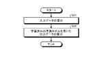
- FIG. 4 is a flow chart relating to the composite structure evaluation method according to the present embodiment.
- FIG. 5 is a flow chart relating to the composite structure evaluation method according to the present embodiment.
- FIG. 6 is a flow chart of a method for manufacturing a composite structure according to this embodiment.
- the prediction model learning method, the composite structure evaluation method, the composite structure manufacturing method, and the composite structure evaluation apparatus according to the present embodiment are a laminate as a composite structure formed by laminating fiber sheets S. It is for predicting the physical quantity of 1.
- the physical quantities to be predicted include the breaking load, strength, etc., at a predetermined portion of the laminate 1 when a load is applied to the laminate 1 .
- the laminate 1 is used as the composite structure, but any combination of a plurality of members may be used, for example, a combination of different materials such as a composite material and a metal material. good too.
- FIG. 1 is a perspective view of an example schematically showing a laminate.
- FIG. 2 is a diagram relating to the composite structure evaluation apparatus according to the present embodiment.
- FIG. 3 is an explanatory diagram of a prediction model.
- FIG. 4 is a flow chart relating to the composite structure evaluation method according to the present embodiment.
- FIG. 5 is a flow chart relating to the composite structure evaluation method according to the present embodiment.
- FIG. 6 is a flow chart of a method for manufacturing a composite structure according to this embodiment.
- the laminate 1 is formed by arranging and laminating a plurality of fiber sheets S in the lamination direction and integrally molding them.
- the fiber sheet S is, for example, a prepreg in which reinforcing fibers are impregnated with a resin, and is a unidirectional material in which the fibers are oriented in one direction.
- the laminate 1 is laminated in the lamination direction by varying the orientation angle of each fiber sheet S. As shown in FIG.
- the laminate 1 is provided with a through hole 5 penetrating in the lamination direction. In the composite structure evaluation method, the area around the through hole 5 is set as an evaluation target area, and the physical quantity in the target area is predicted.
- the prediction model M evaluation device 10 is a device for predicting physical quantities in a target region of the laminate 1 .
- the evaluation device 10 also functions as a learning device for learning a prediction model M for predicting the physical quantity in the target region of the laminate 1 .
- the evaluation device 10 and the learning device are integrated, but are not particularly limited, and may be configured as separate bodies.
- the evaluation device 10 includes a control unit 15 and a storage unit 16.
- the storage unit 16 stores programs and data.
- the storage unit 16 may also function as a work area that temporarily stores the processing results of the control unit 15 .
- the memory unit 16 may include any memory device such as a semiconductor memory device and a magnetic memory device.
- the storage unit 16 includes a prediction model M as a program.
- the prediction model M is a learning model that predicts the physical quantity in the target area of the laminate 1 .
- the prediction model M is a learning model using a neural network. Note that the prediction model M is not limited to a neural network, and may be any learning model that can execute machine learning and deep reinforcement learning.
- the storage unit 16 stores input data D1 and output data D2 as data.
- the input data D1 includes stress distribution data D1a regarding the stress distribution of each fiber sheet S in the target region, and stiffness distribution data D1b regarding the stiffness distribution of each fiber sheet S in the target region.
- the input data D1 is obtained, for example, by stress-analyzing the target region.
- the output data D2 includes breaking load data D2a regarding the breaking load in the target area and position data D2b regarding the coordinate position associated with the breaking load. Further, in the present embodiment, the stress distribution data D1a regarding the stress distribution was used as the input data D1, but the strain distribution data regarding the strain distribution may be used instead of the stress distribution. It may be obtained by strain analysis of the region.
- the control unit 15 executes programs and exchanges data with the storage unit 16.
- the control unit 15 includes, for example, an integrated circuit such as a CPU (Central Processing Unit). Specifically, the control unit 15 executes learning of the prediction model M using the input data D1 and the output data D2 stored in the storage unit 16 . Further, the control unit 15 uses the input data D1 as an input and uses the learned prediction model M to derive the output data D2.
- CPU Central Processing Unit
- the left side of FIG. 3 is the input data D1, the center of FIG. 3 is the prediction model, and the right side of FIG. 3 is the output data D2.
- the input data D1 is data in a target region of the laminate 1, and the target region is a region including stress peaks.
- the stress distribution data D1a of the input data D1 is, for example, image data of stress distribution, and is prepared corresponding to a plurality of fiber sheets S.
- the stiffness distribution data D1b of the input data D1 is, for example, data indicating the distribution of orientation angles of the fiber sheets S, and is prepared corresponding to a plurality of fiber sheets S.
- the predictive model M derives the output data D2 as a solution.
- the breaking load data D2a of the output data D2 is derived as a breaking load in units such as kN.
- the position data D2b of the output data D2 are coordinate values associated with the breaking load, and the starting point of the breaking is the origin.
- the control unit 15 of the evaluation device 10 executes a step of acquiring input data D1 and output data D2 (step S11).
- the input data D1 and the output data D2 used for learning are teacher data. That is, the input data D1 is the analysis result of stress analysis obtained when a load is applied to the target area of the laminate 1 .
- the output data D2 is the analysis result when the target region of the laminate 1 is analyzed by finite element analysis such as damage progression analysis that simulates the occurrence and progression of damage. Note that the output data D2 is not particularly limited to analysis data, and may be strength test data.
- the control unit 15 inputs the input data D1 and the output data D2 to the prediction model M, and executes step S12 for learning the prediction model M (step S12).
- step S21 for deriving the input data D1 for each fiber sheet S in the target area of the laminate 1.
- step S21 the input data D1 obtained when the stress analysis is performed on the target region of the laminate 1 by appropriately changing the parameters related to the structure of the laminate 1 is obtained.
- step S22 the control unit 15 executes a step of inputting the input data D1 to the prediction model M and deriving the output data D2 (step S22).
- step S22 the control unit 15 terminates the processing related to the evaluation method. Therefore, in the evaluation method of the laminate 1, the output data D2 can be obtained without performing the damage progress analysis.
- the output data D2 obtained in the evaluation method may be used in an optimization model for optimizing the strength of the laminate 1.
- step S31 of laminating the fiber sheets S based on the lamination pattern P of the laminate 1 designed based on the evaluation result by the evaluation device 10 is executed. do.
- step S31 for example, the fiber sheets S are stacked using an automatic stacking device that automatically stacks the fiber sheets S. That is, in step S31, by inputting the lamination pattern P into the automatic lamination device, the fiber sheets S are laminated so as to form a predetermined lamination pattern P.
- step S32 of forming the laminate 1 by integrating the laminated fiber sheets S is performed.
- step S32 when the fiber sheet S is a reinforcing fiber sheet impregnated with a thermosetting resin, the resin is thermally cured by heating to integrate the plurality of laminated fiber sheets S into a laminate. 1.
- the prediction model learning method, the composite structure evaluation method, the composite structure manufacturing method, and the composite structure evaluation apparatus 10 described in the present embodiment are understood as follows, for example.
- the learning method of the prediction model M predicts the physical quantity in the target area when a load is applied to the composite structure (laminate 1) in which a plurality of members (fiber sheets S) are combined.
- a step S12 of learning the prediction model M so as to be performed.
- the composite structure is a laminate 1 formed by laminating a plurality of fiber sheets S as the members.
- the stiffness distribution (rigidity distribution data D1b) for each member in the target region corresponding to the stress distribution is further acquired, and the predictive model M is obtained.
- the prediction model M is learned using the stress distribution and the stiffness distribution as inputs.
- the target area is an area including stress peaks.
- the prediction model M is a neural network.
- the training data is the input data D1 of the analysis result of stress analysis when a load is applied to the target area of the composite structure, and the finite element analysis that simulates the occurrence and progress of damage. Let the analysis result obtained by the above be the output data D2.
- a method for evaluating a composite structure according to a seventh aspect uses the predictive model M learned by the method for learning the predictive model M described above, and calculates the physical quantity in the target region when a load is applied by the evaluation device 10.
- the evaluation method for a composite structure predicting using and a step S22 of inputting and deriving the physical quantity in the target area.
- a method for manufacturing a composite structure according to an eighth aspect is a method for manufacturing a composite structure for manufacturing the composite structure evaluated by the method for evaluating a composite structure described above, wherein the evaluated composite structure A step S31 of combining a plurality of the components and a step S32 of forming the composite structure by integrating the combined components are executed.
- a composite structure evaluation apparatus 10 is a composite structure evaluation apparatus that evaluates the composite structure using the prediction model learned by the prediction model learning method described above.
- a control unit that performs a step of deriving the stress distribution for each of the members in the target area; and a step of inputting the derived stress distribution into the prediction model and deriving the physical quantity in the target area.
Landscapes
- Engineering & Computer Science (AREA)
- Theoretical Computer Science (AREA)
- Physics & Mathematics (AREA)
- Evolutionary Computation (AREA)
- Software Systems (AREA)
- General Physics & Mathematics (AREA)
- General Engineering & Computer Science (AREA)
- Artificial Intelligence (AREA)
- Computing Systems (AREA)
- Mathematical Physics (AREA)
- Data Mining & Analysis (AREA)
- Biomedical Technology (AREA)
- Molecular Biology (AREA)
- General Health & Medical Sciences (AREA)
- Computational Linguistics (AREA)
- Biophysics (AREA)
- Life Sciences & Earth Sciences (AREA)
- Health & Medical Sciences (AREA)
- Computer Hardware Design (AREA)
- Geometry (AREA)
- Computer Vision & Pattern Recognition (AREA)
- Medical Informatics (AREA)
- Investigating Strength Of Materials By Application Of Mechanical Stress (AREA)
Abstract
複数の部材を組み合わせた複合構造体に対して、荷重を付加したときの対象領域における物理量を予測するための予測モデルを、学習装置を用いて学習する予測モデルの学習方法であって、前記学習装置に、前記対象領域の前記部材毎の応力分布または歪分布と、前記応力分布または前記歪分布に対応する前記対象領域の前記物理量とを教師データとして取得するステップと、前記教師データの前記応力分布または前記歪分布を入力とし、前記教師データの前記物理量が出力となるように、前記予測モデルを学習させるステップと、を実行させる。
Description
本開示は、予測モデルの学習方法、複合構造体の評価方法、複合構造体の製造方法及び複合構造体の評価装置に関するものである。
従来、外力が作用した場合の構造物の物理量を予測する物理量予測装置が知られている(例えば、特許文献1参照)。物理量予測装置は、構造物の形状データ、特性、境界条件等を入力として、有限要素解析を行うことにより、解析結果を出力する。そして、物理量予測装置は、学習モデルに基づいて、得られた解析結果から構造物の物理量を予測している。
ところで、荷重が付加される構造体としては、複数の部材が組み合わされた複合構造体があり、例えば、繊維シートを複数積層した複合材等の積層体がある。積層体の強度は、積層体の形状、積層構成、荷重条件等の多くのパラメータによって変動する。ここで、特許文献1の物理量予測装置では、構造物の形状データ、特性、境界条件等を入力とし、有限要素解析及び学習モデルを用いた予測を行うことで、構造物の物理量を予測している。この場合、解析コスト(解析時間)が高くなってしまうことから、例えば、パラメータを変動させて多数の解析を実行することも困難となる。
そこで、本開示は、複合構造体の構造に関するパラメータを変更する場合であっても、荷重を付加したときの複合構造体における物理量を、迅速に効率よく予測することができる予測モデルの学習方法、複合構造体の評価方法、複合構造体の製造方法及び複合構造体の評価装置を提供することを課題とする。
本開示の予測モデルの学習方法は、複数の部材を組み合わせた複合構造体に対して、荷重を付加したときの対象領域における物理量を予測するための予測モデルを、学習装置を用いて学習する予測モデルの学習方法であって、前記学習装置に、前記対象領域の前記部材毎の応力分布または歪分布と、前記応力分布または前記歪分布に対応する前記対象領域の前記物理量とを教師データとして取得するステップと、前記教師データの前記応力分布または前記歪分布を入力とし、前記教師データの前記物理量が出力となるように、前記予測モデルを学習させるステップと、を実行させる。
本開示の複合構造体の評価方法は、上記の予測モデルの学習方法により学習した前記予測モデルを用いて、荷重を付加したときの前記対象領域における前記物理量を、評価装置を用いて予測する複合構造体の評価方法であって、前記評価装置に、前記対象領域の前記部材毎の前記応力分布または前記歪分布を導出するステップと、導出した前記応力分布を前記予測モデルに入力して、前記対象領域における前記物理量を導出するステップと、を実行させる。
本開示の複合構造体の製造方法は、上記の複合構造体の評価方法により評価された前記複合構造体を製造する複合構造体の製造方法であって、評価された前記複合構造体となるように、複数の前記部品を組み合わせるステップと、組み合わせた複数の前記部品を一体化させて前記複合構造体を形成するステップと、を実行する。
本開示の複合構造体の評価装置は、上記の予測モデルの学習方法により学習した前記予測モデルを用いて、前記複合構造体を評価する複合構造体の評価装置であって、前記対象領域の前記部材毎の前記応力分布または前記歪分布を導出するステップと、導出した前記応力分布または前記歪分布を前記予測モデルに入力して、前記対象領域における前記物理量を導出するステップと、を実行する制御部を備える。
本開示によれば、荷重を付加したときの複合構造体における物理量を、迅速に効率よく予測することができる。
以下に、本開示に係る実施形態を図面に基づいて詳細に説明する。なお、この実施形態によりこの発明が限定されるものではない。また、下記実施形態における構成要素には、当業者が置換可能かつ容易なもの、あるいは実質的に同一のものが含まれる。さらに、以下に記載した構成要素は適宜組み合わせることが可能であり、また、実施形態が複数ある場合には、各実施形態を組み合わせることも可能である。
[本実施形態]
本実施形態に係る予測モデルの学習方法、複合構造体の評価方法、複合構造体の製造方法及び複合構造体の評価装置は、繊維シートSを積層して形成される複合構造体としての積層体1の物理量を予測するためのものである。予測する物理量としては、積層体1に対して荷重を付加したときの積層体1の所定部位における破壊荷重、強度等である。なお、本実施形態では、複合構造体として、積層体1を適用したが、複数の部材を組み合わせたものであればよく、例えば、複合材と金属材との異材同士を組み合わせたものであってもよい。
本実施形態に係る予測モデルの学習方法、複合構造体の評価方法、複合構造体の製造方法及び複合構造体の評価装置は、繊維シートSを積層して形成される複合構造体としての積層体1の物理量を予測するためのものである。予測する物理量としては、積層体1に対して荷重を付加したときの積層体1の所定部位における破壊荷重、強度等である。なお、本実施形態では、複合構造体として、積層体1を適用したが、複数の部材を組み合わせたものであればよく、例えば、複合材と金属材との異材同士を組み合わせたものであってもよい。
図1は、積層体を模式的に示す一例の斜視図である。図2は、本実施形態に係る複合構造体の評価装置に関する図である。図3は、予測モデルに関する説明図である。図4は、本実施形態に係る複合構造体の評価方法に関するフローチャートである。図5は、本実施形態に係る複合構造体の評価方法に関するフローチャートである。図6は、本実施形態に係る複合構造体の製造方法に関するフローチャートである。
(積層体)
図1に示すように、積層体1は、複数の繊維シートSを積層方向に並べて積層し、一体成形することで形成されるものである。繊維シートSは、例えば、強化繊維に樹脂を含侵させたプリプレグであり、繊維の配向方向が一方向となる一方向材となっている。積層体1は、各繊維シートSの配向角度を異ならせて、積層方向に積層されている。この積層体1には、積層方向に貫通して形成される貫通孔5が設けられている。複合構造体の評価方法では、貫通孔5周りを評価の対象領域として、対象領域における物理量を予測している。
図1に示すように、積層体1は、複数の繊維シートSを積層方向に並べて積層し、一体成形することで形成されるものである。繊維シートSは、例えば、強化繊維に樹脂を含侵させたプリプレグであり、繊維の配向方向が一方向となる一方向材となっている。積層体1は、各繊維シートSの配向角度を異ならせて、積層方向に積層されている。この積層体1には、積層方向に貫通して形成される貫通孔5が設けられている。複合構造体の評価方法では、貫通孔5周りを評価の対象領域として、対象領域における物理量を予測している。
(予測モデルの評価装置)
予測モデルMの評価装置10は、積層体1の対象領域における物理量を予測する装置となっている。また、評価装置10は、積層体1の対象領域における物理量を予測するための予測モデルMを学習するための学習装置としても機能している。なお、本実施形態では、評価装置10と学習装置とは、一体となっているが、特に限定されず、別体として構成してもよい。
予測モデルMの評価装置10は、積層体1の対象領域における物理量を予測する装置となっている。また、評価装置10は、積層体1の対象領域における物理量を予測するための予測モデルMを学習するための学習装置としても機能している。なお、本実施形態では、評価装置10と学習装置とは、一体となっているが、特に限定されず、別体として構成してもよい。
図2に示すように、評価装置10は、制御部15と、記憶部16とを備えている。
記憶部16は、プログラム及びデータを記憶している。また、記憶部16は、制御部15の処理結果を一時的に記憶する作業領域としても機能してもよい。記憶部16は、半導体記憶デバイス、及び磁気記憶デバイス等の任意の記憶デバイスを含んでよい。
記憶部16は、プログラムとして、予測モデルMを含む。予測モデルMは、積層体1の対象領域における物理量を予測する学習モデルである。予測モデルMは、ニューラルネットワークを用いた学習モデルである。なお、予測モデルMは、ニューラルネットワークに限定されず、機械学習、深層強化学習を実行可能な学習モデルであれば、いずれであってもよい。記憶部16は、データとして、入力データD1と出力データD2とを記憶している。入力データD1は、対象領域における繊維シートS毎の応力分布に関する応力分布データD1aと、対象領域における繊維シートS毎の剛性分布に関する剛性分布データD1bと、を含む。入力データD1は、例えば、対象領域を応力解析することで得られる。出力データD2は、対象領域における破壊荷重に関する破壊荷重データD2aと、破壊荷重に対応付けられた座標位置に関する位置データD2bとを含む。また、本実施形態では、入力データD1として、応力分布に関する応力分布データD1aを用いたが、応力分布に代えて、歪分布に関する歪分布データを用いてもよく、歪分布データは、例えば、対象領域を歪解析することで取得してもよい。
制御部15は、プログラムを実行したり、記憶部16との間でデータを授受したりする。制御部15は、例えば、CPU(Central Processing Unit)等の集積回路を含んでいる。具体的に、制御部15は、記憶部16に記憶されている入力データD1及び出力データD2を用いて、予測モデルMの学習を実行している。また、制御部15は、入力データD1を入力として、学習済みの予測モデルMを用いて、出力データD2を導出している。
ここで、図3を参照して、制御部15により、予測モデルMを用いた、出力データD2の導出について説明する。図3の左側は、入力データD1となっており、図3の中央は、予測モデルとなっており、図3の右側は、出力データD2となっている。入力データD1は、積層体1の対象領域におけるデータとなっており、対象領域は、応力ピークを含む領域となっている。入力データD1の応力分布データD1aは、例えば、応力分布の画像データであり、複数の繊維シートSに対応して用意される。入力データD1の剛性分布データD1bは、例えば、繊維シートSの配向角度の分布を示すデータであり、複数の繊維シートSに対応して用意される。図3では、入力データD1が入力されると、予測モデルMにより、出力データD2が解として導出される。出力データD2の破壊荷重データD2aは、破壊荷重として、kN等の単位で導出される。出力データD2の位置データD2bは、破壊荷重に対応付けられた座標値であり、破壊の起点を原点としている。
(予測モデルの学習方法)
次に、図4を参照して、上記の評価装置10を用いた予測モデルMの学習方法について説明する。
次に、図4を参照して、上記の評価装置10を用いた予測モデルMの学習方法について説明する。
図4に示すように、予測モデルMの学習方法において、先ず、評価装置10の制御部15は、入力データD1及び出力データD2を取得するステップを実行する(ステップS11)。学習に用いられる入力データD1及び出力データD2は、教師データとなっている。つまり、入力データD1は、積層体1の対象領域に対して、荷重を付加したときに得られる応力解析の解析結果である。出力データD2は、積層体1の対象領域に対して、損傷の発生及び進展を模擬した損傷進展解析等の有限要素解析を解析したときの解析結果である。なお、出力データD2は、解析データに特に限定されず、強度試験データであってもよい。続いて、制御部15は、入力データD1及び出力データD2を予測モデルMに入力して、予測モデルMを学習させるステップS12を実行する(ステップS12)。
(積層体の評価方法)
次に、図5を参照して、上記の評価装置10を用いた積層体1の評価方法について説明する。
次に、図5を参照して、上記の評価装置10を用いた積層体1の評価方法について説明する。
図5に示すように、積層体1の評価方法において、先ず、評価装置10の制御部15は、積層体1の対象領域の繊維シートS毎の入力データD1を導出するステップS21を実行する。ステップS21では、積層体1の対象領域に対して、積層体1の構造に関するパラメータを適宜変更して応力解析したときの入力データD1を取得する。続いて、制御部15は、入力データD1を予測モデルMに入力して、出力データD2を導出するステップを実行する(ステップS22)。制御部15は、ステップS22の実行後、評価方法に関する処理を終了する。このため、積層体1の評価方法では、損傷進展解析を行うことなく、出力データD2を得ることができる。
なお、評価方法において得られた出力データD2は、積層体1の強度を最適化するための最適化モデルで用いられてもよい。
(積層体の製造方法)
次に、図6を参照して、上記の評価装置10による評価結果に基づいて設計された積層体1を製造する積層体1の製造方法について説明する。
次に、図6を参照して、上記の評価装置10による評価結果に基づいて設計された積層体1を製造する積層体1の製造方法について説明する。
図6に示すように、積層体1の製造方法では、先ず、評価装置10による評価結果に基づいて設計された積層体1の積層パターンPに基づいて、繊維シートSを積層するステップS31を実行する。ステップS31では、例えば、繊維シートSを自動で積層する自動積層装置を用いて繊維シートSを積層する。つまり、ステップS31では、自動積層装置に、積層パターンPを入力することで、所定の積層パターンPとなるように繊維シートSを積層する。続いて、積層体1の製造方法では、積層した繊維シートSを一体化して積層体1を形成するステップS32を実行する。ステップS32では、繊維シートSが、熱硬化性樹脂を含侵させた強化繊維シートである場合には、加熱により樹脂を熱硬化させることで、積層した複数の繊維シートSを一体化して積層体1とする。
以上のように、本実施形態に記載の予測モデルの学習方法、複合構造体の評価方法、複合構造体の製造方法及び複合構造体の評価装置10は、例えば、以下のように把握される。
第1の態様に係る予測モデルMの学習方法は、複数の部材(繊維シートS)を組み合わせた複合構造体(積層体1)に対して、荷重を付加したときの対象領域における物理量を予測するための予測モデルMを、学習装置(評価装置10)を用いて学習する予測モデルMの学習方法であって、前記学習装置に、前記対象領域の前記部材毎の応力分布(応力分布データD1a)と、前記応力分布に対応する前記対象領域の前記物理量(出力データD2)とを教師データとして取得するステップS11と、前記教師データの前記応力分布を入力とし、前記教師データの前記物理量が出力となるように、前記予測モデルMを学習させるステップS12と、を実行させる。
この構成によれば、応力分布を入力とし、物理量を出力する予測モデルMとすることができる。このため、対象領域の応力分布から、応力分布に対応する対象領域の物理量を、予測モデルを用いて予測することができる。これにより、荷重を付加したときの複合構造体における物理量を、迅速に効率よく予測することができる。
第2の態様として、前記複合構造体は、前記部材としての繊維シートSを複数積層して形成される積層体1である。
この構成によれば、荷重を付加したときの積層体1における物理量を、迅速に効率よく予測することができる。
第3の態様として、前記教師データを取得するステップS11では、前記応力分布に対応する、前記対象領域の前記部材毎の剛性分布(剛性分布データD1b)を、さらに取得し、前記予測モデルMを学習させるステップS12では、前記応力分布及び前記剛性分布を入力として、前記予測モデルMを学習させる。
この構成によれば、応力分布の他、剛性分布を踏まえた予測を行うこと可能となるため、予測精度の向上を図ることができる。
第4の態様として、前記対象領域は、応力ピークを含む領域となっている。
この構成によれば、応力分布を的確にとらえた対象領域とすることができるため、予測精度の向上をさらに図ることができる。
第5の態様として、前記予測モデルMは、ニューラルネットワークである。
この構成によれば、一般的な予測モデルMを用いることができるため、予測モデルMの構築に係るコストの増大を抑制することができる。
第6の態様として、前記教師データは、前記複合構造体の対象領域に対して、荷重を付加したときの応力解析の解析結果を入力データD1とし、損傷の発生及び進展を模擬した有限要素解析により得られた解析結果を出力データD2とする。
この構成によれば、教師データの解となる出力データD2として、解析精度の高い損傷進展解析の解析結果を用いることができるため、予測精度の向上をさらに図ることができる。
第7の態様に係る複合構造体の評価方法は、上記の予測モデルMの学習方法により学習した前記予測モデルMを用いて、荷重を付加したときの前記対象領域における前記物理量を、評価装置10を用いて予測する複合構造体の評価方法であって、前記評価装置10に、前記対象領域の前記部材毎の前記応力分布を導出するステップS21と、導出した前記応力分布を前記予測モデルMに入力して、前記対象領域における前記物理量を導出するステップS22と、を実行させる。
この構成によれば、対象領域における物理量を導出するにあたって、例えば、計算負荷の大きい損傷進展解析を行う必要がない。このため、応力分布を入力とし、予測モデルMを用いることで、対象領域における物理量を迅速に導出することができる。
第8の態様に係る複合構造体の製造方法は、上記の複合構造体の評価方法により評価された前記複合構造体を製造する複合構造体の製造方法であって、評価された前記複合構造体となるように、複数の前記部品を組み合わせるステップS31と、組み合わせた複数の前記部品を一体化させて前記複合構造体を形成するステップS32と、を実行する。
この構成によれば、荷重負荷による物理量が適切に評価された複合構造体を製造することができる。
第9の態様に係る複合構造体の評価装置10は、上記の予測モデルの学習方法により学習した前記予測モデルを用いて、前記複合構造体を評価する複合構造体の評価装置であって、前記対象領域の前記部材毎の前記応力分布を導出するステップと、導出した前記応力分布を前記予測モデルに入力して、前記対象領域における前記物理量を導出するステップと、を実行する制御部を備える。
この構成によれば、対象領域における物理量を導出するにあたって、例えば、計算負荷の大きい損傷進展解析を行う必要がない。このため、応力分布を入力とし、予測モデルMを用いることで、対象領域における物理量を迅速に導出することができる。
1 積層体
10 評価装置
15 制御部
16 記憶部
S 繊維シート
M 予測モデル
D1 入力データ
D2 出力データ
10 評価装置
15 制御部
16 記憶部
S 繊維シート
M 予測モデル
D1 入力データ
D2 出力データ
Claims (9)
- 複数の部材を組み合わせた複合構造体に対して、荷重を付加したときの対象領域における物理量を予測するための予測モデルを、学習装置を用いて学習する予測モデルの学習方法であって、
前記学習装置に、
前記対象領域の前記部材毎の応力分布または歪分布と、前記応力分布または前記歪分布に対応する前記対象領域の前記物理量とを教師データとして取得するステップと、
前記教師データの前記応力分布または前記歪分布を入力とし、前記教師データの前記物理量が出力となるように、前記予測モデルを学習させるステップと、を実行させる予測モデルの学習方法。 - 前記複合構造体は、前記部材としての繊維シートを複数積層して形成される積層体である請求項1に記載の予測モデルの学習方法。
- 前記教師データを取得するステップでは、前記応力分布に対応する、前記対象領域の前記部材毎の剛性分布を、さらに取得し、
前記予測モデルを学習させるステップでは、前記応力分布及び前記剛性分布を入力として、前記予測モデルを学習させる請求項1または2に記載の予測モデルの学習方法。 - 前記対象領域は、応力または歪のピークを含む領域となっている請求項1から3のいずれか1項に記載の予測モデルの学習方法。
- 前記予測モデルは、ニューラルネットワークである請求項1から4のいずれか1項に記載の予測モデルの学習方法。
- 前記教師データは、前記複合構造体の対象領域に対して、荷重を付加したときの応力解析の解析結果を入力データとし、損傷の発生及び進展を模擬した有限要素解析により得られた解析結果を出力データとする請求項1から5のいずれか1項に記載の予測モデルの学習方法。
- 請求項1から6のいずれか1項に記載の予測モデルの学習方法により学習した前記予測モデルを用いて、荷重を付加したときの前記対象領域における前記物理量を、評価装置を用いて予測する複合構造体の評価方法であって、
前記評価装置に、
前記対象領域の前記部材毎の前記応力分布または前記歪分布を導出するステップと、
導出した前記応力分布または前記歪分布を前記予測モデルに入力して、前記対象領域における前記物理量を導出するステップと、を実行させる複合構造体の評価方法。 - 請求項7に記載の複合構造体の評価方法により評価された前記複合構造体を製造する複合構造体の製造方法であって、
評価された前記複合構造体となるように、複数の前記部材を組み合わせるステップと、
組み合わせた複数の前記部材を一体化させて前記複合構造体を形成するステップと、を実行する複合構造体の製造方法。 - 請求項1から6のいずれか1項に記載の予測モデルの学習方法により学習した前記予測モデルを用いて、前記複合構造体を評価する複合構造体の評価装置であって、
前記対象領域の前記部材毎の前記応力分布または前記歪分布を導出するステップと、
導出した前記応力分布または前記歪分布を前記予測モデルに入力して、前記対象領域における前記物理量を導出するステップと、を実行する制御部を備える複合構造体の評価装置。
Applications Claiming Priority (2)
| Application Number | Priority Date | Filing Date | Title |
|---|---|---|---|
| JP2021007445A JP7788216B2 (ja) | 2021-01-20 | 2021-01-20 | 予測モデルの学習方法、複合構造体の評価方法、複合構造体の製造方法及び複合構造体の評価装置 |
| JP2021-007445 | 2021-01-20 |
Publications (1)
| Publication Number | Publication Date |
|---|---|
| WO2022158447A1 true WO2022158447A1 (ja) | 2022-07-28 |
Family
ID=82549452
Family Applications (1)
| Application Number | Title | Priority Date | Filing Date |
|---|---|---|---|
| PCT/JP2022/001600 Ceased WO2022158447A1 (ja) | 2021-01-20 | 2022-01-18 | 予測モデルの学習方法、複合構造体の評価方法、複合構造体の製造方法及び複合構造体の評価装置 |
Country Status (2)
| Country | Link |
|---|---|
| JP (1) | JP7788216B2 (ja) |
| WO (1) | WO2022158447A1 (ja) |
Citations (4)
| Publication number | Priority date | Publication date | Assignee | Title |
|---|---|---|---|---|
| JP2004110793A (ja) * | 2002-08-28 | 2004-04-08 | Toyota Motor Corp | 積層材料内の層間応力演算方法 |
| JP2019032768A (ja) * | 2017-08-09 | 2019-02-28 | 三菱重工業株式会社 | 複合材の設計方法、及び複合材 |
| JP2019106188A (ja) * | 2017-12-13 | 2019-06-27 | ダッソー システムズ シムリア コーポレイション | シミュレーションシナリオをオーサリングする方法およびシステム |
| JP2019128815A (ja) * | 2018-01-25 | 2019-08-01 | トヨタ自動車株式会社 | 物理量予測装置 |
Family Cites Families (1)
| Publication number | Priority date | Publication date | Assignee | Title |
|---|---|---|---|---|
| WO2020229883A1 (en) * | 2019-05-16 | 2020-11-19 | Spherene Ag | Method for the lightweighting and/or designing of an additively manufactured article |
-
2021
- 2021-01-20 JP JP2021007445A patent/JP7788216B2/ja active Active
-
2022
- 2022-01-18 WO PCT/JP2022/001600 patent/WO2022158447A1/ja not_active Ceased
Patent Citations (4)
| Publication number | Priority date | Publication date | Assignee | Title |
|---|---|---|---|---|
| JP2004110793A (ja) * | 2002-08-28 | 2004-04-08 | Toyota Motor Corp | 積層材料内の層間応力演算方法 |
| JP2019032768A (ja) * | 2017-08-09 | 2019-02-28 | 三菱重工業株式会社 | 複合材の設計方法、及び複合材 |
| JP2019106188A (ja) * | 2017-12-13 | 2019-06-27 | ダッソー システムズ シムリア コーポレイション | シミュレーションシナリオをオーサリングする方法およびシステム |
| JP2019128815A (ja) * | 2018-01-25 | 2019-08-01 | トヨタ自動車株式会社 | 物理量予測装置 |
Also Published As
| Publication number | Publication date |
|---|---|
| JP7788216B2 (ja) | 2025-12-18 |
| JP2022111785A (ja) | 2022-08-01 |
Similar Documents
| Publication | Publication Date | Title |
|---|---|---|
| JP5972062B2 (ja) | 複合材積層板の屈曲繊維経路の設計 | |
| CN111125946B (zh) | 一种基于mdo技术的上车体结构优化方法 | |
| JP2017211887A (ja) | 有限要素法解析方法、有限要素法解析装置、解析サービスシステムおよび有限要素法解析プログラムを記録した記録媒体 | |
| de Almeida | Stacking sequence optimization for maximum buckling load of composite plates using harmony search algorithm | |
| Cousigné et al. | Numerical modeling of nonlinearity, plasticity and damage in CFRP-woven composites for crash simulations | |
| JP2018156689A (ja) | 低い単位面積重量を有する多重プライ積層複合材 | |
| Li et al. | Modified Levenberg–Marquardt algorithm for backpropagation neural network training in dynamic model identification of mechanical systems | |
| Sahin et al. | Smart structures and their applications on active vibration control: Studies in the Department of Aerospace Engineering, METU | |
| Noh et al. | Failure analysis of glass/epoxy and graphite/epoxy laminates due to the effect of variation in lamination scheme and angle of fibre orientation | |
| KR101507750B1 (ko) | 복합재 구조물의 최적설계 방법 | |
| Waimer et al. | Integrative numerical techniques for fibre reinforced polymers-forming process and analysis of differentiated anisotropy | |
| Abdullah | Nonlinear dynamic modeling and vibration analysis of smart composite structures using multiscale techniques | |
| Crnjac et al. | Two-stage product design selection by using PROMETHEE and Taguchi method: A case study. | |
| JP7788216B2 (ja) | 予測モデルの学習方法、複合構造体の評価方法、複合構造体の製造方法及び複合構造体の評価装置 | |
| Galińska | Material models used to predict spring-in of composite elements: a comparative study | |
| Wesolowski et al. | Model errors influence on identified composite material properties | |
| US20200124509A1 (en) | Method of Predicting Joining Strength of Joined Dissimilar Materials | |
| Cong et al. | Methodology for evaluating manufacturability of composite materials | |
| White et al. | Investigation of shear characterization of a UHMWPE unidirectional cross-ply for finite element simulation of composite processing | |
| JP2019207128A (ja) | 建物損傷検知装置、建物損傷検知モデル学習装置、建物損傷検知方法、建物損傷検知モデル学習方法、プログラム | |
| WO2019215965A1 (ja) | Frpの最適化システム、frpの最適化装置、frpの信頼性評価方法 | |
| Benadero et al. | Dynamic analysis of self-oscillating H-bridge inverters with state feedback | |
| Schläpfer et al. | Optimal design and testing of laminated light-weight composite structures with local reinforcements considering strength constraints part i: design | |
| US20240083136A1 (en) | Training method for learning device, method for designing design pattern, method for manufacturing laminate, and design device for design pattern | |
| Lubimyi et al. | Methodology for the Selection of Optimal Parameters of the Finite Element Mesh in Composite Materials Calculation |
Legal Events
| Date | Code | Title | Description |
|---|---|---|---|
| 121 | Ep: the epo has been informed by wipo that ep was designated in this application |
Ref document number: 22742569 Country of ref document: EP Kind code of ref document: A1 |
|
| NENP | Non-entry into the national phase |
Ref country code: DE |
|
| 122 | Ep: pct application non-entry in european phase |
Ref document number: 22742569 Country of ref document: EP Kind code of ref document: A1 |