WO2022157886A1 - パラメータ最適化システム、パラメータ最適化方法、及びコンピュータプログラム - Google Patents
パラメータ最適化システム、パラメータ最適化方法、及びコンピュータプログラム Download PDFInfo
- Publication number
- WO2022157886A1 WO2022157886A1 PCT/JP2021/002043 JP2021002043W WO2022157886A1 WO 2022157886 A1 WO2022157886 A1 WO 2022157886A1 JP 2021002043 W JP2021002043 W JP 2021002043W WO 2022157886 A1 WO2022157886 A1 WO 2022157886A1
- Authority
- WO
- WIPO (PCT)
- Prior art keywords
- parameter
- score
- sensing
- optimization system
- parameters
- Prior art date
- Legal status (The legal status is an assumption and is not a legal conclusion. Google has not performed a legal analysis and makes no representation as to the accuracy of the status listed.)
- Ceased
Links
Images









Classifications
-
- H—ELECTRICITY
- H04—ELECTRIC COMMUNICATION TECHNIQUE
- H04N—PICTORIAL COMMUNICATION, e.g. TELEVISION
- H04N23/00—Cameras or camera modules comprising electronic image sensors; Control thereof
- H04N23/70—Circuitry for compensating brightness variation in the scene
- H04N23/71—Circuitry for evaluating the brightness variation
-
- H—ELECTRICITY
- H04—ELECTRIC COMMUNICATION TECHNIQUE
- H04N—PICTORIAL COMMUNICATION, e.g. TELEVISION
- H04N23/00—Cameras or camera modules comprising electronic image sensors; Control thereof
- H04N23/80—Camera processing pipelines; Components thereof
- H04N23/82—Camera processing pipelines; Components thereof for controlling camera response irrespective of the scene brightness, e.g. gamma correction
-
- G—PHYSICS
- G06—COMPUTING OR CALCULATING; COUNTING
- G06T—IMAGE DATA PROCESSING OR GENERATION, IN GENERAL
- G06T7/00—Image analysis
- G06T7/0002—Inspection of images, e.g. flaw detection
-
- G—PHYSICS
- G06—COMPUTING OR CALCULATING; COUNTING
- G06T—IMAGE DATA PROCESSING OR GENERATION, IN GENERAL
- G06T7/00—Image analysis
- G06T7/80—Analysis of captured images to determine intrinsic or extrinsic camera parameters, i.e. camera calibration
-
- H—ELECTRICITY
- H04—ELECTRIC COMMUNICATION TECHNIQUE
- H04N—PICTORIAL COMMUNICATION, e.g. TELEVISION
- H04N23/00—Cameras or camera modules comprising electronic image sensors; Control thereof
- H04N23/60—Control of cameras or camera modules
-
- G—PHYSICS
- G06—COMPUTING OR CALCULATING; COUNTING
- G06T—IMAGE DATA PROCESSING OR GENERATION, IN GENERAL
- G06T2207/00—Indexing scheme for image analysis or image enhancement
- G06T2207/10—Image acquisition modality
- G06T2207/10141—Special mode during image acquisition
- G06T2207/10152—Varying illumination
-
- G—PHYSICS
- G06—COMPUTING OR CALCULATING; COUNTING
- G06T—IMAGE DATA PROCESSING OR GENERATION, IN GENERAL
- G06T2207/00—Indexing scheme for image analysis or image enhancement
- G06T2207/30—Subject of image; Context of image processing
- G06T2207/30168—Image quality inspection
Definitions
- This disclosure relates to the technical field of a parameter optimization system, a parameter optimization method, and a computer program that optimize the parameters of an image sensor.
- Patent Document 1 discloses a technique for generating an estimated image of a target based on an image data set obtained by linking a captured image and lighting parameters, and optimizing the lighting parameters by machine learning using it.
- Patent Document 2 discloses a technique of optimizing an imaging parameter estimator by performing regression learning using an imaging parameter that maximizes a category determination score as a teacher value.
- Patent Document 3 discloses a technique of selecting and using recognition control parameters corresponding to an imaging environment in which a camera device is installed from a parameter table updated using a predetermined learning algorithm.
- This disclosure aims to improve the related technology described above.
- One aspect of the parameter optimization system disclosed herein includes an image sensor having at least one sensing parameter, parameter setting means capable of changing the sensing parameter, and a score for calculating a score from an image acquired by the image sensor. and parameter determining means for determining an appropriate parameter, which is the sensing parameter for which the score is relatively high, based on the sensing parameter and the score corresponding to the sensing parameter.
- One aspect of the parameter optimization method of this disclosure is a parameter optimization system for an image sensor having at least one modifiable sensing parameter, wherein a score is calculated from an image acquired with the image sensor, and the sensing Based on the parameters and the scores corresponding to the sensing parameters, a proper parameter, which is the sensing parameter with which the score is relatively high, is determined.
- One aspect of the computer program of this disclosure is a parameter optimization system for an image sensor having at least one modifiable sensing parameter, wherein a score is calculated from an image acquired with the image sensor, and the sensing parameter and , and the score corresponding to the sensing parameter, determine a proper parameter, which is the sensing parameter for which the score is relatively high.
- FIG. 1 is a block diagram showing the hardware configuration of a parameter optimization system according to a first embodiment
- FIG. 1 is a block diagram showing a functional configuration of a parameter optimization system according to a first embodiment
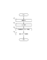
- FIG. 4 is a flow chart showing the operation flow of the parameter optimization system according to the first embodiment
- FIG. 7 is a block diagram showing the functional configuration of a parameter optimization system according to the second embodiment
- FIG. It is a table showing an example of sensing parameters handled by the parameter optimization system according to the second embodiment.
- FIG. 11 is a block diagram showing the functional configuration of a parameter optimization system according to a third embodiment
- FIG. 10 is a flow chart showing the operation flow of the parameter optimization system according to the third embodiment
- FIG. 11 is a block diagram showing the functional configuration of a parameter optimization system according to a fourth embodiment
- FIG. 14 is a flow chart showing the operation flow of the parameter optimization system according to the fourth embodiment
- FIG. 11 is a block diagram showing the functional configuration of a parameter optimization system according to a fifth embodiment
- FIG. FIG. 16 is a flow chart showing the operation flow of the parameter optimization system according to the fifth embodiment
- FIG. FIG. 12 is a block diagram showing a functional configuration of a parameter optimization system according to a sixth embodiment
- FIG. FIG. 16 is a flow chart showing the operation flow of the parameter optimization system according to the sixth embodiment
- FIG. FIG. 22 is a block diagram showing the functional configuration of a parameter optimization system according to the seventh embodiment
- FIG. 14 is a flow chart showing the flow of operations of a parameter optimization system according to the seventh embodiment
- FIG. FIG. 21 is a conceptual diagram showing an example of the difference in light environment in the parameter optimization system according to the seventh embodiment
- FIG. 22 is a block diagram showing a functional configuration of a parameter optimization system according to an eighth embodiment
- FIG. FIG. 16 is a flow chart showing the operation flow of the parameter optimization system according to the eighth embodiment
- FIG. FIG. 21 is a diagram (part 1) showing a presentation example in the parameter optimization system according to the eighth embodiment
- FIG. 22 is a diagram (part 2) showing a presentation example in the parameter optimization system according to the eighth embodiment
- FIG. 1 is a block diagram showing the hardware configuration of the parameter optimization system according to the first embodiment.
- the parameter optimization system 10 includes a processor 11, a RAM (Random Access Memory) 12, a ROM (Read Only Memory) 13, and a storage device 14. .
- Parameter optimization system 10 may comprise an input device 15 and an output device 16 .
- Parameter optimization system 10 further comprises camera 20 .
- Processor 11 , RAM 12 , ROM 13 , storage device 14 , input device 15 , output device 16 and camera 20 are connected via data bus 17 .
- the processor 11 reads a computer program.
- processor 11 is configured to read a computer program stored in at least one of RAM 12, ROM 13 and storage device .
- the processor 11 may read a computer program stored in a computer-readable recording medium using a recording medium reader (not shown).
- the processor 11 may acquire (that is, read) a computer program from a device (not shown) arranged outside the parameter optimization system 10 via a network interface.
- the processor 11 controls the RAM 12, the storage device 14, the input device 15 and the output device 16 by executing the read computer program.
- functional blocks for optimizing the sensing parameters of the image sensor are implemented in the processor 11 .
- Examples of the processor 11 include a CPU (Central Processing Unit), GPU (Graphics Processing Unit), FPGA (Field-Programmable Gate Array), DSP (Demand-Side Platform), and ASIC (Application Specific Integrate).
- the processor 11 may use one of the examples described above, or may use a plurality of them in parallel.
- the RAM 12 temporarily stores computer programs executed by the processor 11.
- the RAM 12 temporarily stores data temporarily used by the processor 11 while the processor 11 is executing the computer program.
- the RAM 12 may be, for example, a D-RAM (Dynamic RAM).
- the ROM 13 stores computer programs executed by the processor 11 .
- the ROM 13 may also store other fixed data.
- the ROM 13 may be, for example, a P-ROM (Programmable ROM).
- the storage device 14 stores data that the parameter optimization system 10 saves for a long time.
- Storage device 14 may act as a temporary storage device for processor 11 .
- the storage device 14 may include, for example, at least one of a hard disk device, a magneto-optical disk device, an SSD (Solid State Drive), and a disk array device.
- the input device 15 is a device that receives input instructions from the user of the parameter optimization system 10 .
- Input device 15 may include, for example, at least one of a keyboard, mouse, and touch panel.
- the input device 15 may be a dedicated controller (operation terminal).
- the input device 15 may include a terminal owned by the user (for example, a smart phone, a tablet terminal, or the like).
- the input device 15 may be a device capable of voice input including, for example, a microphone.
- the output device 16 is a device that outputs information about the parameter optimization system 10 to the outside.
- output device 16 may be a display device (eg, display) capable of displaying information regarding parameter optimization system 10 .
- the display device here may be a television monitor, a personal computer monitor, a smart phone monitor, a tablet terminal monitor, or a monitor of other mobile terminals.
- the display device may be a large monitor, digital signage, or the like installed in various facilities such as stores.
- the output device 16 may be a device that outputs information in a format other than an image.
- output device 16 may be a speaker that audibly outputs information about parameter optimization system 10 .
- the camera 20 is configured as a device capable of capturing an image.
- the camera 20 may be a visible light camera, or a camera such as an infrared camera that captures an image using light other than visible light.
- the camera 20 may be a camera that captures still images, or may be a camera that captures moving images.
- the camera 20 is configured with an image sensor (image sensor) having sensing parameters. Details of the image sensor will be described later.
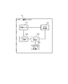
- FIG. 2 is a block diagram showing the functional configuration of the parameter optimization system according to the first embodiment
- the parameter optimization system 10 includes an image sensor 110, a parameter setting unit 120, a score calculation unit 130, and a parameter determination unit as components for realizing its functions. and a part 140 .
- the image sensor 110 is a sensor included in the above-described camera 20 (see FIG. 1).
- each of the parameter setting unit 120, the score calculation unit 130, and the parameter determination unit 140 may be implemented by the above-described processor (FIG. 1).
- the image sensor 110 is configured as a sensor capable of acquiring an image.
- the specific configuration of the image sensor 110 is not particularly limited, for example, it may be configured as a CCD (Charge Coupled Devices) or as a CMOS (Complementary Metal Oxide Semiconductor).
- Image sensor 110 has at least one sensing parameter (ie, a parameter related to capturing an image). Specific examples of sensing parameters will be described in detail in other embodiments described later.
- the parameter setting unit 120 is configured to be able to set (that is, change) sensing parameters of the image sensor 110 .
- the parameter setting unit 120 may be able to set them collectively or separately one by one.
- Parameter setting section 120 is configured to be able to output information about the currently set sensing parameter to parameter determining section 140 .
- the score calculation unit 130 is configured to be able to calculate a score from the image acquired by the image sensor 110.
- the “score” here is a numerical representation of the state of the image, and may be, for example, a value indicating the quality of the image, or a value indicating the detection result or recognition result of the imaging target included in the image. There may be. More specifically, the score may be a face authentication score that indicates the degree of matching (similarity) of faces in face authentication. Since existing techniques can be appropriately adopted for a specific score calculation method, detailed description thereof will be omitted here.
- the score calculated by the score calculator 130 is configured to be output to the parameter determiner 140 .
- the parameter determination unit 140 is configured to be able to determine an appropriate parameter with a relatively high score, using the information regarding the sensing parameters acquired from the parameter setting unit 120 and the information regarding the score calculated by the score calculation unit 130. ing. A more specific method of determining appropriate parameters will be described in detail in another embodiment described later.
- a suitable parameter may be a sensing parameter that gives the highest image score in the current shooting environment.
- the correct parameter may be a sensing parameter such that the score of the image is higher than a predetermined threshold. If the image sensor 110 has a plurality of sensing parameters, the parameter determination unit 140 may determine all appropriate parameters, or may determine a portion of the appropriate parameters.
- FIG. 3 is a flow chart showing the operation flow of the parameter optimization system according to the first embodiment.
- the image sensor 110 first acquires an image (step S11).
- the score calculator 130 calculates a score from the image acquired by the image sensor 110 (step S12).
- the score calculated by score calculation section 130 is output to parameter determination section 140 .
- the parameter determination unit 140 acquires from the parameter setting unit 120 information about the sensing parameters when the image for which the score is calculated is captured (step S13).
- the parameter determination unit 140 determines appropriate parameters based on the score and information on sensing parameters corresponding to the score (step S14). A method of using the appropriate parameters determined here will be described in detail in another embodiment described later.
- appropriate parameters are determined based on sensing parameters of the image sensor 110 and scores calculated from images. By doing so, it is possible to capture an image with a high score by setting appropriate sensing parameters. For this reason, even if the initial values of the sensing parameters are values that are not suitable for score calculation (for example, values that are set to capture an image that is easy for the human eye to see), the sensing parameters can be reconfigured and scored. An image suitable for calculating is captured. Also, it is possible to capture an appropriate image regardless of the environment (particularly, the light environment) in which the image is captured.
- FIG. 4 A parameter optimization system 10 according to the second embodiment will be described with reference to FIGS. 4 and 5.
- FIG. 4 is a block diagram showing the functional configuration of the parameter optimization system according to the second embodiment.
- symbol is attached
- the parameter optimization system 10 includes an image sensor 110, a parameter setting unit 120, a score calculation unit 130, and a parameter determination unit as components for realizing its functions. and a part 140 .
- the score calculator 130 according to the second embodiment includes a neural network 135 .
- the neural network 135 is configured as a trained model that calculates scores from images.
- the neural network 135 may be, for example, CNN (Convolution Neural Network), RNN (Recurrent Neural Network), LSTM (Long Short Term Memory), Transformer, or GAN (Generative Adversarial Network).
- the neural network 135 may be configured as a face recognition model that performs face recognition using face images.
- neural network 135 may be configured as an object recognition model that recognizes objects present in images.
- FIG. 5 is a table showing an example of sensing parameters handled by the parameter optimization system according to the second embodiment.
- the sensing parameters shown in FIG. 5 are parameters related to the setting values of the imaging device, and are parameters for which gradients cannot be calculated by error backpropagation of the neural network.
- a parameter optimization system determines appropriate parameters for such sensing parameters. Specifically, analog parameters such as exposure time, analog gain, F-number (aperture value), focal length (field of view), and flash are included. In addition, parameters such as white balance, brightness, digital gain, noise removal, etc., which are digital parameters, can be used. Note that the parameters given here are only examples, and other sensing parameters may be used as long as the parameters cannot calculate gradients by error backpropagation of a neural network.
- the parameter optimization system 10 determines appropriate parameters for parameters whose gradients cannot be calculated by error backpropagation of the neural network. In this case, even if a neural network is provided, it cannot be used to determine proper parameters. However, in the parameter optimization system 10 according to the second embodiment, as already described, appropriate parameters are determined based on the sensing parameters of the image sensor 110 and scores calculated from images. Therefore, proper parameters can be determined without using a neural network. That is, it is possible to appropriately determine appropriate parameters even for parameters whose gradients cannot be calculated by error backpropagation of a neural network.
- FIG. 6 A parameter optimization system 10 according to the third embodiment will be described with reference to FIGS. 6 and 7.
- FIG. 6 A parameter optimization system 10 according to the third embodiment will be described with reference to FIGS. 6 and 7.
- FIG. 6 It should be noted that the third embodiment may differ from the above-described first and second embodiments only in a part of configuration and operation, and may be the same as the first and second embodiments in other respects. Therefore, in the following, portions different from the already described embodiments will be described in detail, and descriptions of other overlapping portions will be omitted as appropriate.
- FIG. 6 is a block diagram showing the functional configuration of the parameter optimization system according to the third embodiment.
- symbol is attached
- the parameter optimization system 10 includes an image sensor 110, a parameter setting unit 120, a score calculation unit 130, and a parameter determination unit as components for realizing its functions.
- a section 140 and an information storage section 150 are provided. That is, the parameter optimization system 10 according to the third embodiment further includes an information storage unit 150 in addition to the components of the first embodiment (see FIG. 2).
- the information storage unit 150 may be realized by, for example, the above-described storage device 14 (see FIG. 1).
- the information storage unit 150 is configured to be able to store a pair of the score calculated by the score calculation unit 130 and the information on the sensing parameter acquired from the parameter setting unit 120 (hereinafter referred to as "pair information" as appropriate). .
- the information storage unit 150 stores pair information each time a new image is acquired and a score is calculated. Therefore, the information storage unit 150 accumulates a plurality of pieces of pair information.
- the pair information stored in the information storage unit 150 can be appropriately read by the parameter determination unit 140 .
- FIG. 7 is a flow chart showing the operation flow of the parameter optimization system according to the third embodiment.
- the same reference numerals are given to the same processes as those shown in FIG.
- the image sensor 110 first acquires an image (step S11). Then, the score calculator 130 calculates a score from the image acquired by the image sensor 110 (step S12).
- the information storage unit 150 stores a pair (that is, pair information) of the score calculated by the score calculation unit 130 and the information on the sensing parameter acquired from the parameter setting unit 120 (step S31).
- the parameter optimization system 10 determines whether or not to finish accumulating pair information (step S32). Whether or not to end the accumulation of pair information may be determined by, for example, whether or not the number of accumulated pair information has reached a predetermined number.
- the "predetermined value” in this case may be a value set in advance by simulation or the like as the number of pieces of pair information sufficient to determine the appropriate parameter in step S33, which will be described later.
- whether or not to end accumulation of pair information may be determined by whether or not pair information corresponding to all prepared images has been accumulated.
- step S32: NO When it is determined not to finish accumulating pair information (step S32: NO), the parameter optimization system 10 according to the third embodiment repeats the process from step S11. As a result, pair information is accumulated in the information storage unit 150 . On the other hand, if it is determined to finish accumulating pair information (step S32: NO), the parameter determination unit 140 determines appropriate parameters based on the pair information accumulated in the information storage unit 150 (step S33).
- the appropriate parameters determined by the parameter determining section 140 may be reflected by the parameter setting section 120 immediately after being determined. That is, once the proper parameters are determined, the sensing parameters of the image sensor 110 may be immediately changed to the proper parameters.
- the appropriate parameters determined by the parameter determination unit 140 may be reflected by the parameter setting unit 120 after the above-described system is actually operated. That is, the determined appropriate parameters are not immediately reflected, but may be reflected in the sensing parameters of the image sensor 110 as needed.
- the parameter optimization system 10 determines appropriate parameters based on the pair information accumulated in the information storage unit 150.
- FIG. the appropriate parameters can be determined using a plurality of pieces of paired information (that is, a plurality of scores and a plurality of sensing parameters) accumulated in the information storage unit 150. Therefore, the appropriate parameters can be determined from a small amount of information. It is possible to determine the appropriate parameter as a more appropriate value compared to the case of determination.
- FIG. 8 A parameter optimization system 10 according to the fourth embodiment will be described with reference to FIGS. 8 and 9.
- FIG. 8 A parameter optimization system 10 according to the fourth embodiment will be described with reference to FIGS. 8 and 9.
- FIG. 8 A parameter optimization system 10 according to the fourth embodiment will be described with reference to FIGS. 8 and 9.
- FIG. 8 A parameter optimization system 10 according to the fourth embodiment will be described with reference to FIGS. 8 and 9.
- FIG. 8 A parameter optimization system 10 according to the fourth embodiment will be described with reference to FIGS. 8 and 9.
- FIG. 8 A parameter optimization system 10 according to the fourth embodiment will be described with reference to FIGS. 8 and 9.
- FIG. 8 A parameter optimization system 10 according to the fourth embodiment will be described with reference to FIGS. 8 and 9.
- FIG. 8 is a block diagram showing the functional configuration of the parameter optimization system according to the fourth embodiment.
- symbol is attached
- the parameter optimization system 10 according to the fourth embodiment includes an image sensor 110, a parameter setting unit 120, a score calculation unit 130, and a parameter determination unit as components for realizing its functions.
- a section 140 and a score storage section 160 are provided. That is, the parameter optimization system 10 according to the fourth embodiment further includes a score storage unit 160 in addition to the components of the first embodiment (see FIG. 2).
- the score storage unit 160 may be realized by, for example, the above-described storage device 14 (see FIG. 1).
- the parameter determination unit 140 according to the fourth embodiment is configured with a gradient calculation unit 145 .
- the score storage unit 160 is configured to be able to store the score calculated by the score calculation unit 130 and the sensing parameters (hereinafter sometimes simply referred to as “parameters”) when the image for which the score was calculated was taken.
- the score storage unit 160 accumulates the scores and parameters that are sequentially calculated in this way.
- the score storage unit 160 may be capable of storing only two scores and parameters that are calculated consecutively. In other words, the score storage unit 160 may store at least two scores and parameters. Also, the score storage unit 160 may have a function of appropriately deleting scores and parameters that are no longer required to be stored.
- the scores and parameters stored in the score storage unit 160 can be appropriately read by the parameter determination unit 140 (specifically, the gradient calculation unit 145).
- the gradient calculation unit 145 is configured to be able to calculate gradients of parameters from a plurality of scores stored in the score storage unit 160 and parameters.
- the gradient calculation unit 145 may calculate the gradient of a parameter by calculating the difference between a plurality of scores and parameters and dividing the score difference by the amount of change in the parameter.
- the gradient calculator 145 may calculate the parameter gradient from two scores and parameters, or may calculate the parameter gradient from three or more scores and parameters.
- the gradients of the parameters calculated by the gradient calculator 145 are used by the parameter determiner 140 to determine appropriate parameters.
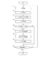
- FIG. 9 is a flow chart showing the operation flow of the parameter optimization system according to the fourth embodiment.
- the same reference numerals are assigned to the same processes as those shown in FIG.
- the image sensor 110 first acquires an image (step S11).
- the image sensor 110 sequentially acquires images.
- the image sensor 110 is configured as an image sensor of a camera that captures moving images, and continuously acquires images of a plurality of frames.
- the score calculator 130 calculates a score from the image acquired by the image sensor 110 (step S12). Then, the score storage unit 160 stores the score and parameters calculated by the score calculation unit 130 (step S41).
- the gradient calculation unit 145 in the parameter determination unit 140 calculates gradients of parameters from the multiple scores and parameters stored in the score storage unit 160 (step S42). Then, the parameter determination unit 140 determines appropriate parameters based on the gradients of the parameters calculated by the gradient calculation unit 145 (step S43).
- the parameter setting unit 120 updates (changes) the sensing parameters of the image sensor 110 according to the appropriate parameters determined by the parameter determination unit 140 (step S44). Therefore, in the parameter optimization system 10 according to the fourth embodiment, the sensing parameters of the image sensor 110 are updated each time a new appropriate parameter is determined.
- the parameter optimization system 10 determines whether image acquisition by the image sensor 110 is finished (step S45). If the acquisition of the image ends (step S45: YES), the series of processing ends. On the other hand, if image acquisition has not ended (step S45: NO), the parameter optimization system 10 according to the fourth embodiment repeats the process from step S11. Therefore, while images are being acquired by the image sensor 110 (that is, while images are being captured), the process of determining appropriate parameters from the parameter gradients and updating the sensing parameters of the image sensor 110 is repeatedly executed.
- the parameter optimization system 10 according to the fourth embodiment can be used even when image acquisition is not completed, when the appropriate parameters have converged to a specific value (in other words, there is little significance in updating the sensing parameters).
- the above-described series of processes may be stopped.
- the parameter optimization system 10 according to the fourth embodiment is in a situation where the sensing parameters of the image sensor should be updated again (for example, when the optical environment around the image sensor 110 changes etc.), the series of processes may be started again.
- appropriate parameters are determined according to gradients of parameters that are sequentially calculated, and each time a new appropriate parameter is determined, The sensing parameters of image sensor 110 are updated. By doing so, it is possible to search for the optimum appropriate parameter while acquiring images sequentially. Therefore, for example, when shooting a moving image, appropriate shooting can be realized while reflecting the sensing parameters according to the environment at that time as needed. Such an effect is remarkably exhibited when images are continuously captured in a situation where the light environment around the image sensor 110 changes with the passage of time (for example, from day to evening, from evening to night, etc.). be.
- FIG. 10 A parameter optimization system 10 according to the fifth embodiment will be described with reference to FIGS. 10 and 11.
- FIG. 10 A parameter optimization system 10 according to the fifth embodiment will be described with reference to FIGS. 10 and 11.
- FIG. 10 It should be noted that the fifth embodiment may differ from the above-described fourth embodiment only in a part of the configuration and operation, and the other parts may be the same as those of the fourth embodiment. Therefore, in the following, portions different from the already described embodiments will be described in detail, and descriptions of other overlapping portions will be omitted as appropriate.
- FIG. 10 is a block diagram showing the functional configuration of the parameter optimization system according to the fifth embodiment.
- symbol is attached
- the parameter optimization system 10 includes an image sensor 110, a parameter setting unit 120, a score calculation unit 130, and a parameter determination unit as components for realizing its functions. It includes a section 140 , a score storage section 160 and a noise amount calculation section 170 . That is, the parameter optimization system 10 according to the fifth embodiment further includes a noise amount calculator 170 in addition to the components of the fourth embodiment (see FIG. 8). Note that the noise amount calculator 170 may be implemented by, for example, the above-described processor 11 (see FIG. 1).
- the noise amount calculator 170 is configured to be able to calculate the noise amount included in the score calculated by the score calculator 130 .
- the “noise amount” here is the amount of noise that is included in the score calculated from the image acquired by the image sensor 110 due to the noise in the image.
- a method of calculating the amount of noise is not particularly limited, but for example, a plurality of images may be acquired in advance by the image sensor 110 and the amount of noise may be calculated using the standard deviation or the like from those images.
- the noise amount calculated by the noise amount calculation unit 170 is configured to be output to the parameter determination unit 140 .
- FIG. 11 is a flow chart showing the operation flow of the parameter optimization system according to the fifth embodiment.
- the same reference numerals are given to the same processes as those shown in FIG.
- the image sensor 110 first acquires an image (step S11).
- the image sensor 110 sequentially acquires images as in the fourth embodiment.
- the image sensor 110 is configured as an image sensor of a camera that captures moving images, and continuously acquires images of a plurality of frames.
- the score calculator 130 calculates a score from the image acquired by the image sensor 110 (step S12). Then, the score storage unit 160 stores the score and parameters calculated by the score calculation unit 130 (step S41).
- the noise amount calculation unit 170 calculates the noise amount of the score (step S51).
- the calculation of the amount of noise may be performed before the calculation of the score in step S12 and the storage of the score in step S41.
- the process of calculating the amount of noise may be executed before step S11. In other words, the process of calculating the noise amount may be executed before the series of processes in FIG. 11 is started.
- the parameter determination unit 140 determines whether or not the score difference used when the gradient of the parameter is calculated by the gradient calculation unit 145 is greater than the noise amount calculated by the noise amount calculation unit 170 (step S52 ).
- step S52 If the score difference is greater than the amount of noise (step S52: YES), the gradient calculation unit 145 in the parameter determination unit 140 calculates the parameter gradient from the multiple scores and parameters stored in the score storage unit 160. (Step S42). Then, the parameter determination unit 140 determines appropriate parameters based on the gradients of the parameters calculated by the gradient calculation unit 145 (step S43). After that, the parameter setting unit 120 updates the sensing parameters of the image sensor 110 according to the appropriate parameters determined by the parameter determining unit 140 (step S44).
- step S52 YES
- the above-described steps S42 to S44 are omitted. That is, in this case, the process of calculating the slope of the parameter, the process of determining the appropriate parameter based on the slope of the parameter, and the process of updating the sensing parameter according to the appropriate parameter are not executed.
- the process of determining whether or not the score difference in step S52 is greater than the amount of noise may be performed after the gradient of the parameter is calculated in step S42. In this case, when the score difference is smaller than the amount of noise, the processing of steps S43 and S44 is omitted. In other words, the slope of the parameter is calculated, but the process of determining the appropriate parameter and the process of updating the sensing parameter may not be performed. Further, the process of determining whether or not the score difference in step S52 is greater than the amount of noise may be performed after determining the appropriate parameter in step S43. In this case, if the score difference is smaller than the amount of noise, only the process of step S44 is omitted. That is, although the process of calculating the slope of the parameter and the process of determining the appropriate parameter are executed, the sensing parameter may not be updated according to the appropriate parameter.
- the parameter optimization system 10 determines whether or not image acquisition by the image sensor 110 is finished (step S45). If the acquisition of the image ends (step S45: YES), the series of processing ends. On the other hand, if image acquisition has not ended (step S45: NO), the parameter optimization system 10 according to the fifth embodiment repeats the process from step S11.
- the parameter optimization system 10 compares the score difference and the amount of noise, and determines whether or not to update the sensing parameter according to the result. be done. In this way, the sensing parameter can be updated after determining the significance of the score difference based on the amount of noise. Specifically, when the score difference is greater than the noise amount, it is determined that the score difference is significant (the error is not caused by noise), the sensing parameters are updated, and the score difference is greater than the noise amount. If it is small, it can be determined that the score difference is not significant (the error is due to noise), and the sensing parameters can be updated.
- FIG. 12 A parameter optimization system 10 according to the sixth embodiment will be described with reference to FIGS. 12 and 13.
- FIG. 12 A parameter optimization system 10 according to the sixth embodiment will be described with reference to FIGS. 12 and 13.
- FIG. 12 A parameter optimization system 10 according to the sixth embodiment will be described with reference to FIGS. 12 and 13.
- FIG. 12 A parameter optimization system 10 according to the sixth embodiment will be described with reference to FIGS. 12 and 13.
- FIG. 12 A parameter optimization system 10 according to the sixth embodiment will be described with reference to FIGS. 12 and 13.
- FIG. 12 A parameter optimization system 10 according to the sixth embodiment will be described with reference to FIGS. 12 and 13.
- FIG. 12 A parameter optimization system 10 according to the sixth embodiment will be described with reference to FIGS. 12 and 13.
- FIG. 12 is a block diagram showing the functional configuration of the parameter optimization system according to the sixth embodiment.
- symbol is attached
- the parameter optimization system 10 includes an image sensor 110, a parameter setting unit 120, a score calculation unit 130, and a parameter determination unit as components for realizing its functions. and a part 140 .
- the parameter setting section 120 according to the fourth embodiment is configured with a detection determination section 125 .
- the detection determination unit 125 is configured to be able to determine whether or not the imaging target is detected from the image based on the score calculated by the score calculation unit 130 . Specifically, the detection determination unit 125 determines whether the imaging target is detected from the image based on whether the score calculated by the score calculating unit 130 is a value corresponding to a state in which the imaging target is not detected. It is configured to be able to determine whether or not Note that the score calculated by the score calculation unit 130 according to the sixth embodiment is a value that changes according to the imaging target detected from the image. For example, the score calculator 130 detects a person's face from an image and calculates a score indicating whether or not the face is a registered face.
- the score calculated by the score calculation unit 130 changes according to, for example, the degree of matching between the face detected from the image and the registered face. However, if no human face is detected, the score will be "0". In such an example, the detection determination unit 125 can determine whether or not a face has been detected depending on whether the calculated score is "0" or "other than that.”
- FIG. 13 is a flow chart showing the operation flow of the parameter optimization system according to the sixth embodiment.
- the same reference numerals are assigned to the same processes as those shown in FIG.
- the image sensor 110 first acquires an image (step S11).
- the score calculator 130 calculates a score from the image acquired by the image sensor 110 (step S12).
- the score calculated by the score calculation section 130 is output to the parameter determination section 140 and the detection determination section 125 .
- the detection determination unit 125 determines whether or not the imaging target is detected from the image based on the score calculated by the score calculation unit 120 (step S61). Then, when it is determined that the imaging target is not detected from the image (step S61: NO), the parameter setting unit 120 changes the sensing parameters of the image sensor 110 to Adjustments are made so that the object to be imaged can be detected (step S62). That is, the parameter setting unit 120 adjusts the sensing parameters so that the imaging target can be easily detected. For example, if the image is too dark to detect the object to be imaged, the parameter setting unit 120 changes the brightness parameter among the sensing parameters so that the image captured by the image sensor 110 is brighter. Further, when the image is too bright to detect the imaging target, the parameter setting unit 120 may change the parameter related to brightness among the sensing parameters so that the image acquired by the image sensor 110 is adjusted to be dark. good.
- the parameter optimization system 10 repeats the process from step S11 again. Therefore, if the state in which the imaging target is not detected from the image continues, the sensing parameters are further changed. For example, when adjusting the sensing parameters to brighten the image, the image is adjusted to become brighter.
- the sensing parameters are further changed, the first changed sensing parameter may be changed further, or a sensing parameter other than the first changed sensing parameter may be changed.
- the imaging target will not be detected from the image no matter how the sensing parameters are adjusted. Therefore, if the imaging target cannot be detected even if the sensing parameters are changed by a certain value or more (for example, even if the image is brightened by a certain value or more), the adjusted sensing parameters are returned to the initial values, and an external execution command is issued. Alternatively, it may be shifted to a state of waiting for a periodic execution command.
- the parameter determination unit 140 acquires from the parameter setting unit 120 information about the sensing parameters when the image for which the score was calculated was taken (step S13). Then, parameter determining section 140 determines appropriate parameters based on the scores and information on sensing parameters corresponding to the scores (step S14).
- the sensing parameter is adjusted so that the imaging target can be detected from the image.
- the sensing parameter is adjusted so that the imaging target can be detected from the image.
- the score becomes "0" or the score cannot be substantially calculated. Therefore, if the imaging target cannot be detected from the image, the parameter gradient cannot be calculated. In such situations, it is difficult to determine the appropriate fit parameters.
- the imaging target when the imaging target is not detected from the image, the imaging target is adjusted from the image so that the imaging target can be easily detected (for example, the image is adjusted to be brighter). Therefore, it is possible to reliably detect the object to be imaged from the image and determine suitable parameters.
- FIG. 14 to 16 A parameter optimization system 10 according to the seventh embodiment will be described with reference to FIGS. 14 to 16.
- FIG. The seventh embodiment may differ from the first to sixth embodiments described above only in part in configuration and operation, and the other parts may be the same as those in the first to sixth embodiments. Therefore, in the following, portions different from the already described embodiments will be described in detail, and descriptions of other overlapping portions will be omitted as appropriate.
- FIG. 14 is a block diagram showing the functional configuration of the parameter optimization system according to the seventh embodiment.
- symbol is attached
- the parameter optimization system 10 includes an image sensor 110, a parameter setting unit 120, a score calculation unit 130, and a parameter determination unit as components for realizing its functions. It includes a unit 140 and a parameter storage unit 180 . That is, the parameter optimization system 10 according to the seventh embodiment further includes a parameter storage unit 180 in addition to the components of the first embodiment (see FIG. 2). Note that the parameter storage unit 180 may be implemented by, for example, the above-described storage device 14 (see FIG. 1).
- the parameter storage unit 180 is configured to be able to store a plurality of patterns of appropriate parameters determined by the parameter determination unit 140. More specifically, the parameter storage unit 180 is configured to be able to store a plurality of patterns of appropriate parameters according to the light environment.
- the appropriate parameters stored in the parameter storage unit 180 may be two patterns, or may be three or more patterns.
- FIG. 15 is a flow chart showing the operation flow of the parameter optimization system according to the seventh embodiment.
- the same reference numerals are given to the same processes as those shown in FIG.
- the image sensor 110 first acquires an image (step S11).
- the score calculator 130 calculates a score from the image acquired by the image sensor 110 (step S12).
- the score calculated by score calculation section 130 is output to parameter determination section 140 .
- the parameter determination unit 140 acquires from the parameter setting unit 120 information about the sensing parameters when the image for which the score is calculated is captured (step S13).
- the parameter determination unit 140 determines appropriate parameters based on the score and information on sensing parameters corresponding to the score (step S14).
- the parameter storage unit 180 stores the appropriate parameters determined by the parameter determination unit 140 (step S71). That is, the parameter storage unit 180 stores appropriate parameters for one pattern corresponding to one light environment.
- the parameter optimization system 10 determines whether or not the appropriate parameters for patterns corresponding to all light environments have been stored (step S72). That is, it is determined whether or not a preset number of proper parameters have been stored.
- step S72 If the appropriate parameters for patterns corresponding to all light environments are stored (step S72: YES), the series of processing ends. On the other hand, if appropriate parameters for patterns corresponding to all light environments are not stored (step S72: NO), the light environment is changed (step S73), and the process is repeated from step S11. By repeating the processing from steps S11 to S18 in this manner, a plurality of patterns of appropriate parameters corresponding to different light environments are stored in the parameter storage unit 180.
- FIG. Note that the change in the light environment in step S73 may be realized, for example, by changing the intensity of illumination, or may be realized over time (for example, by waiting for daytime to turn into nighttime). good.
- FIG. 16 is a conceptual diagram showing an example of the difference in light environment in the parameter optimization system according to the seventh embodiment.
- the parameter optimization system 10 stores appropriate parameters corresponding to three light environments, light environment A, light environment B, and light environment C, in the parameter storage unit 180. You may do so.
- the parameter storage unit 180 stores a proper parameter A corresponding to a sunny and bright light environment A, a proper parameter B corresponding to a cloudy and dim light environment B, and a proper parameter C corresponding to a dark and night light environment C. 3 patterns may be stored.
- the above example is merely an example, and multiple patterns of appropriate parameters may be determined according to other light environments.
- the above example assumes outdoor imaging, but in the case of indoor imaging, a plurality of patterns of appropriate parameters may be determined according to, for example, the intensity of illumination.
- multiple patterns of appropriate parameters are stored according to differences in light environment. By doing so, it is possible to appropriately capture an image by selecting an appropriate appropriate parameter from among a plurality of patterns according to the light environment when capturing the image. Therefore, an appropriate image can be captured relatively easily without newly determining appropriate parameters at the timing of capturing the image.
- FIG. 17 to 20 A parameter optimization system 10 according to the eighth embodiment will be described with reference to FIGS. 17 to 20.
- FIG. The eighth embodiment may differ from the above-described seventh embodiment only in a part of configuration and operation, and the other parts may be the same as those of the seventh embodiment. Therefore, in the following, portions different from the already described embodiments will be described in detail, and descriptions of other overlapping portions will be omitted as appropriate.
- FIG. 17 is a block diagram showing a functional configuration of a parameter optimization system according to the eighth embodiment.
- the same reference numerals are given to the same components as those shown in FIG. 17
- the parameter optimization system 10 includes an image sensor 110, a parameter setting unit 120, a score calculation unit 130, and a parameter determination unit 140 as components for realizing its functions. , a parameter storage unit 180 , a pattern presentation unit 190 , and a selection operation detection unit 200 . That is, the parameter optimization system 10 according to the eighth embodiment further includes a pattern presentation unit 190 and a selection operation detection unit 200 in addition to the configuration of the seventh embodiment (see FIG. 14).
- Each of the pattern presentation unit 190 and the selection operation detection unit 200 may be implemented by, for example, the above-described processor 11 (see FIG. 1).
- the pattern presenting unit 190 may be configured including the output device 16 (see FIG. 1) described above.
- the selection operation detection unit 200 may be configured including the above-described input device 15 (see FIG. 1).
- the pattern presentation unit 190 is configured to be able to present multiple patterns of appropriate parameters stored in the parameter storage unit 180 to the user of the system.
- the pattern presentation unit 190 may present a plurality of patterns of appropriate parameters by displaying an image on a display, for example.
- the pattern presenting unit 190 may present a plurality of patterns of appropriate parameters by voice through a speaker or the like.
- the selection operation detection unit 200 is configured to be able to detect a selection operation (that is, an operation of selecting one pattern from among the presented patterns) by a user presented with a plurality of patterns of suitable parameters by the pattern presentation unit 190. there is The selection operation detection unit 200 may be configured to be able to detect a user's terminal operation, for example. Information about the selection operation detected by the selection operation detection unit 200 (for example, information about the pattern selected by the user) is configured to be output to the parameter setting unit 120 .
- FIG. 18 is a flow chart showing the operation flow of the parameter optimization system according to the eighth embodiment. Note that the series of processes shown in FIG. 18 are processes that are executed after determining appropriate parameters for a plurality of patterns. The processing up to determining appropriate parameters for multiple patterns may be the same as in the seventh embodiment (see FIG. 15).
- the pattern presentation unit 190 selects the appropriate parameters of the plurality of patterns stored in the parameter storage unit 180 for the system. Presented to the user (step S81).
- the selection operation detection unit 200 detects a selection operation by the user (step S82). Note that if the selection operation by the user is not detected (for example, if the selection operation is not detected even after a predetermined period of time has passed since the presentation), the user may be notified to perform the selection operation. . Alternatively, any one pattern may be automatically selected without waiting for the user's selection operation.
- the parameter setting section 120 changes the sensing parameters of the image sensor 110 according to the selection operation detected by the selection operation detection section 200 . Specifically, the parameter setting unit 120 changes the sensing parameters of the image sensor 110 so that the parameters are appropriate for the pattern selected by the user's selection operation (step S83).
- the selection operation detection unit 200 may continue detection of the selection operation even after the sensing parameter is changed in step S83. Then, when a user's selection operation is newly detected, the parameter setting unit 120 may change the sensing parameter again according to the newly detected selection operation. In this way, the selection operation detection and sensing parameter change may be performed multiple times.
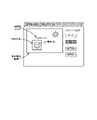
- FIG. 19 is a diagram (part 1) showing a presentation example in the parameter optimization system according to the eighth embodiment
- FIG. 20 is a diagram (part 2) showing a presentation example in the parameter optimization system according to the eighth embodiment. Note that FIGS. 19 and 20 show a presentation example in which a person's face is detected from an image and a face authentication score is calculated.
- the captured image (moving image) is displayed in the left area of the screen.
- the rectangular area containing the detected face and the calculated face authentication score are superimposed and displayed.
- Buttons for setting sensing parameters are arranged on the right side of the screen. Specifically, four buttons of "auto”, “light environment A”, “light environment B”, and “light environment C” are arranged in order from the top. By clicking one of these four buttons, the user can select one pattern from multiple patterns of appropriate parameters (that is, perform a selection operation).
- the user has selected "light environment A” (the color of the button is different from the others). Therefore, at the timing shown in FIG. 19, the image is captured with the proper parameters corresponding to the light environment A.
- the sensing parameters of the image sensor 110 are changed to appropriate parameters corresponding to the light environment B.
- the sensing parameters of the image sensor 110 are changed to appropriate parameters corresponding to light environment C.
- the sensing parameters of the image sensor 110 are appropriate parameters corresponding to one of the light environment A, the light environment B, or the light environment C, or otherwise. is automatically changed to a random sensing parameter of
- a graph showing changes in scores over time is displayed in the lower left area of the screen. Looking at the graph in the time direction, the user first selects “auto”, then selects “light environment A (appropriate parameter A)", and then selects “light environment B (appropriate parameter B)”. , and finally select "light environment C (appropriate parameter C)".
- the score values are compared for each pattern, it can be seen that the score is the highest when the light environment A is selected. Therefore, the user can easily know that the appropriate parameter A according to the light environment A should be selected in order to increase the score.
- a processing method is also implemented in which a program for operating the configuration of each embodiment is recorded on a recording medium so as to realize the functions of each embodiment described above, the program recorded on the recording medium is read as code, and executed by a computer. Included in the category of form. That is, a computer-readable recording medium is also included in the scope of each embodiment. In addition to the recording medium on which the above program is recorded, the program itself is also included in each embodiment.
- a floppy (registered trademark) disk, hard disk, optical disk, magneto-optical disk, CD-ROM, magnetic tape, non-volatile memory card, and ROM can be used as recording media.
- the program recorded on the recording medium alone executes the process, but also the one that operates on the OS and executes the process in cooperation with other software and functions of the expansion board. included in the category of
- the parameter optimization system described in appendix 1 includes an image sensor having at least one sensing parameter, parameter setting means capable of changing the sensing parameter, and score calculation means for calculating a score from an image acquired by the image sensor. and parameter determining means for determining a proper parameter, which is the sensing parameter for which the score is relatively high, based on the sensing parameter and the score corresponding to the sensing parameter. Optimization system.
- the score calculation means includes a neural network
- the sensing parameter is a parameter related to setting values of an imaging device. system.
- the parameter optimization system according to Supplementary Note 3 further comprises information storage means for storing the sensing parameter and the score corresponding to the sensing parameter as paired information, and the parameter determination means stores the information 3.
- the score calculation means calculates the score from a plurality of images that are sequentially acquired, and the parameter determination means calculates the difference between the scores of the plurality of images and the The appropriate parameter is determined based on the slope of the sensing parameter calculated from the difference from the sensing parameter, and the parameter setting means changes the sensing parameter to the newly determined appropriate parameter.
- the parameter optimization system according to Supplementary Note 5 further includes noise calculation means for calculating the amount of noise included in the score, and the parameter determination means determines, when the difference between the scores is smaller than the noise amount, the new 4.
- the score relates to an imaging target included in the image
- the parameter setting means is a value corresponding to a state in which the imaging target is not detected. 6.
- appendix 7 The parameter optimization system according to appendix 7, wherein the parameter determination means determines the appropriate parameters of a plurality of patterns according to the difference in the light environment around the image sensor, any one of appendices 1 to 6
- the parameter optimization system according to appendix 8 further comprises presenting means for presenting the appropriate parameters of the plurality of patterns to the user, and the parameter setting means changes the sensing parameters according to the pattern selected by the user.
- the parameter optimization method of clause 9 is a parameter optimization system for an image sensor having at least one modifiable sensing parameter, wherein a score is calculated from an image acquired by the image sensor, and the sensing parameter and , and the score corresponding to the sensing parameter, a suitable parameter, which is the sensing parameter with which the score becomes relatively high, is determined.
- a recording medium according to appendix 11 is a recording medium characterized in that the computer program according to appendix 10 is recorded.
Landscapes
- Engineering & Computer Science (AREA)
- Multimedia (AREA)
- Signal Processing (AREA)
- Computer Vision & Pattern Recognition (AREA)
- Physics & Mathematics (AREA)
- General Physics & Mathematics (AREA)
- Theoretical Computer Science (AREA)
- Quality & Reliability (AREA)
- Image Analysis (AREA)
- Studio Devices (AREA)
- Image Processing (AREA)
Priority Applications (3)
| Application Number | Priority Date | Filing Date | Title |
|---|---|---|---|
| US17/640,520 US12108167B2 (en) | 2021-01-21 | 2021-01-21 | Optimizing sensing parameter in imaging device using scores |
| JP2022576297A JP7509245B2 (ja) | 2021-01-21 | 2021-01-21 | パラメータ最適化システム、パラメータ最適化方法、及びコンピュータプログラム |
| PCT/JP2021/002043 WO2022157886A1 (ja) | 2021-01-21 | 2021-01-21 | パラメータ最適化システム、パラメータ最適化方法、及びコンピュータプログラム |
Applications Claiming Priority (1)
| Application Number | Priority Date | Filing Date | Title |
|---|---|---|---|
| PCT/JP2021/002043 WO2022157886A1 (ja) | 2021-01-21 | 2021-01-21 | パラメータ最適化システム、パラメータ最適化方法、及びコンピュータプログラム |
Publications (1)
| Publication Number | Publication Date |
|---|---|
| WO2022157886A1 true WO2022157886A1 (ja) | 2022-07-28 |
Family
ID=82548574
Family Applications (1)
| Application Number | Title | Priority Date | Filing Date |
|---|---|---|---|
| PCT/JP2021/002043 Ceased WO2022157886A1 (ja) | 2021-01-21 | 2021-01-21 | パラメータ最適化システム、パラメータ最適化方法、及びコンピュータプログラム |
Country Status (3)
| Country | Link |
|---|---|
| US (1) | US12108167B2 (https=) |
| JP (1) | JP7509245B2 (https=) |
| WO (1) | WO2022157886A1 (https=) |
Families Citing this family (1)
| Publication number | Priority date | Publication date | Assignee | Title |
|---|---|---|---|---|
| US20240185611A1 (en) * | 2022-12-01 | 2024-06-06 | Apollo Autonomous Driving USA LLC | Image signal processing (isp) tuning with downstream perception metric in autonomous driving |
Citations (4)
| Publication number | Priority date | Publication date | Assignee | Title |
|---|---|---|---|---|
| JP2010026591A (ja) * | 2008-07-15 | 2010-02-04 | Panasonic Corp | 標識認識装置及び標識認識方法 |
| JP2019012426A (ja) * | 2017-06-30 | 2019-01-24 | キヤノン株式会社 | 画像認識装置、学習装置、画像認識方法、学習方法及びプログラム |
| WO2019138827A1 (ja) * | 2018-01-12 | 2019-07-18 | 日立オートモティブシステムズ株式会社 | 物体認識装置 |
| JP2020010166A (ja) * | 2018-07-06 | 2020-01-16 | キヤノン株式会社 | 画像処理装置およびその制御方法、撮像装置、プログラム |
Family Cites Families (12)
| Publication number | Priority date | Publication date | Assignee | Title |
|---|---|---|---|---|
| JP6471934B2 (ja) | 2014-06-12 | 2019-02-20 | パナソニックIpマネジメント株式会社 | 画像認識方法、カメラシステム |
| JP6341184B2 (ja) * | 2015-11-18 | 2018-06-13 | カシオ計算機株式会社 | 画像処理装置、画像処理方法及びプログラム |
| JP6942464B2 (ja) * | 2016-12-09 | 2021-09-29 | キヤノン株式会社 | 画像処理装置、画像処理方法、及びプログラム |
| US10565696B2 (en) * | 2017-06-05 | 2020-02-18 | Qualcomm Incorporated | Systems and methods for producing image feedback |
| CN110035451B (zh) | 2018-01-11 | 2020-08-28 | 惠州Tcl移动通信有限公司 | 通信切换方法及通信切换装置 |
| US11336831B2 (en) | 2018-07-06 | 2022-05-17 | Canon Kabushiki Kaisha | Image processing device, control method, and program storage medium |
| EP3654236A3 (en) * | 2018-10-25 | 2020-08-26 | Canon Kabushiki Kaisha | Information processing apparatus, control method of information processing apparatus, storage medium, and imaging system |
| JP7006567B2 (ja) | 2018-11-09 | 2022-01-24 | オムロン株式会社 | 撮影方法及び撮影装置 |
| JP7186128B2 (ja) * | 2019-04-24 | 2022-12-08 | 株式会社日立製作所 | 物品認識システムおよび物品認識方法 |
| US20200364498A1 (en) * | 2019-05-15 | 2020-11-19 | Schlumberger Technology Corporation | Autonomous burner |
| KR102825811B1 (ko) * | 2019-05-21 | 2025-06-27 | 삼성전자주식회사 | 이미지 신호 프로세서의 모델링 방법, 및 전자 기기 |
| EP3944184A1 (en) * | 2020-07-20 | 2022-01-26 | Leica Geosystems AG | Dark image enhancement |
-
2021
- 2021-01-21 US US17/640,520 patent/US12108167B2/en active Active
- 2021-01-21 WO PCT/JP2021/002043 patent/WO2022157886A1/ja not_active Ceased
- 2021-01-21 JP JP2022576297A patent/JP7509245B2/ja active Active
Patent Citations (4)
| Publication number | Priority date | Publication date | Assignee | Title |
|---|---|---|---|---|
| JP2010026591A (ja) * | 2008-07-15 | 2010-02-04 | Panasonic Corp | 標識認識装置及び標識認識方法 |
| JP2019012426A (ja) * | 2017-06-30 | 2019-01-24 | キヤノン株式会社 | 画像認識装置、学習装置、画像認識方法、学習方法及びプログラム |
| WO2019138827A1 (ja) * | 2018-01-12 | 2019-07-18 | 日立オートモティブシステムズ株式会社 | 物体認識装置 |
| JP2020010166A (ja) * | 2018-07-06 | 2020-01-16 | キヤノン株式会社 | 画像処理装置およびその制御方法、撮像装置、プログラム |
Also Published As
| Publication number | Publication date |
|---|---|
| US20230156348A1 (en) | 2023-05-18 |
| JP7509245B2 (ja) | 2024-07-02 |
| JPWO2022157886A1 (https=) | 2022-07-28 |
| US12108167B2 (en) | 2024-10-01 |
Similar Documents
| Publication | Publication Date | Title |
|---|---|---|
| US11119577B2 (en) | Method of controlling an operation of a camera apparatus and a camera apparatus | |
| CN104052905B (zh) | 用于处理图像的方法和设备 | |
| KR101455018B1 (ko) | 촬상 장치, 촬상 방법, 및 컴퓨터 판독 가능한 기록 매체 | |
| KR20190092995A (ko) | 단말기 및 그것의 이미지 처리 방법 | |
| US11954865B2 (en) | Image processing apparatus, image processing method, and storage medium for foreground extraction | |
| KR20170047167A (ko) | 전자 장치가 동영상의 얼굴의 인상을 변형하는 방법 및 그 전자 장치 | |
| CN110572636B (zh) | 摄像头脏污检测方法、装置、存储介质及电子设备 | |
| CN107330859B (zh) | 一种图像处理方法、装置、存储介质及终端 | |
| KR102636558B1 (ko) | 전자 장치, 행동 인스턴스 생성 방법 및 기록 매체 | |
| JPWO2007020789A1 (ja) | 顔画像表示装置、顔画像表示方法及び顔画像表示プログラム | |
| US11710250B2 (en) | Electronic device, method, and storage medium for setting processing procedure for controlling apparatus | |
| US12430777B2 (en) | Image processing apparatus, image processing method, and non-transitory computer-readable storage medium to perform a tracking process, using a tracking model | |
| JP2008259161A (ja) | 目標追尾装置 | |
| CN112487888A (zh) | 一种基于目标对象的图像采集方法及装置 | |
| CN112437231A (zh) | 图像拍摄方法和装置、电子设备及存储介质 | |
| JP7509245B2 (ja) | パラメータ最適化システム、パラメータ最適化方法、及びコンピュータプログラム | |
| JP2020181290A (ja) | 物品認識システムおよび物品認識方法 | |
| JP5835035B2 (ja) | 文字認識用のプログラムおよび文字認識装置 | |
| JP6230386B2 (ja) | 画像処理装置、画像処理方法及び画像処理プログラム | |
| KR102070598B1 (ko) | 카메라 장치 및 그의 제어 방법 | |
| CN114341946B (zh) | 识别方法、装置、电子设备及存储介质 | |
| CN114630086B (zh) | 投影系统以及用于影像拼接的取像数量选择方法 | |
| CN119152803A (zh) | 一种户外led显示屏的控制方法及系统 | |
| CN113099110B (zh) | 照明摄影装置的移动参数校正方法、校正装置及拍摄系统 | |
| CN120188492A (zh) | 用于确定相机自动聚焦的感兴趣区的方法 |
Legal Events
| Date | Code | Title | Description |
|---|---|---|---|
| 121 | Ep: the epo has been informed by wipo that ep was designated in this application |
Ref document number: 21920998 Country of ref document: EP Kind code of ref document: A1 |
|
| ENP | Entry into the national phase |
Ref document number: 2022576297 Country of ref document: JP Kind code of ref document: A |
|
| NENP | Non-entry into the national phase |
Ref country code: DE |
|
| 122 | Ep: pct application non-entry in european phase |
Ref document number: 21920998 Country of ref document: EP Kind code of ref document: A1 |