WO2022153991A1 - 通信制御方法 - Google Patents
通信制御方法 Download PDFInfo
- Publication number
- WO2022153991A1 WO2022153991A1 PCT/JP2022/000642 JP2022000642W WO2022153991A1 WO 2022153991 A1 WO2022153991 A1 WO 2022153991A1 JP 2022000642 W JP2022000642 W JP 2022000642W WO 2022153991 A1 WO2022153991 A1 WO 2022153991A1
- Authority
- WO
- WIPO (PCT)
- Prior art keywords
- mbs
- session
- base station
- signaling
- control method
- Prior art date
- Legal status (The legal status is an assumption and is not a legal conclusion. Google has not performed a legal analysis and makes no representation as to the accuracy of the status listed.)
- Ceased
Links
Images









Classifications
-
- H—ELECTRICITY
- H04—ELECTRIC COMMUNICATION TECHNIQUE
- H04W—WIRELESS COMMUNICATION NETWORKS
- H04W76/00—Connection management
- H04W76/40—Connection management for selective distribution or broadcast
-
- H—ELECTRICITY
- H04—ELECTRIC COMMUNICATION TECHNIQUE
- H04W—WIRELESS COMMUNICATION NETWORKS
- H04W4/00—Services specially adapted for wireless communication networks; Facilities therefor
- H04W4/06—Selective distribution of broadcast services, e.g. multimedia broadcast multicast service [MBMS]; Services to user groups; One-way selective calling services
-
- H—ELECTRICITY
- H04—ELECTRIC COMMUNICATION TECHNIQUE
- H04W—WIRELESS COMMUNICATION NETWORKS
- H04W76/00—Connection management
- H04W76/20—Manipulation of established connections
- H04W76/27—Transitions between radio resource control [RRC] states
Definitions
- the present disclosure relates to a communication control method used in a mobile communication system.
- NR New Radio
- RAT Radio Access Technology
- LTE Long Term Evolution
- the communication control method is a communication control method used in a mobile communication system that provides a multicast broadcast service (MBS) from a base station to a user apparatus, and the base station is at least a broadcast session.
- MBS multicast broadcast service
- the MBS setting including the information necessary for reception is transmitted by broadcast signaling, and the base station determines at least a part of the MBS setting for the user device in the RRC (Radio Resource Control) connected state. It has to transmit by decaded signaling.
- RRC Radio Resource Control
- the communication control method is a communication control method used in a mobile communication system that provides a multicast broadcast service (MBS) from a base station to a user device, and the base station distributes the MBS.
- MBS multicast broadcast service
- the mode specification information that specifies one of the first distribution mode and the second distribution mode as the mode is transmitted to the user apparatus, and the first distribution mode has the MBS setting required for MBS reception. It is a distribution mode in which the base station transmits the MBS setting to the user apparatus by broadcast signaling from the base station, and the second distribution mode is a distribution mode in which the MBS setting is transmitted from the base station to the user apparatus by broadcast signaling. ..
- the communication control method is a communication control method used in a mobile communication system that provides a multicast broadcast service (MBS) from a base station to a user device, wherein the user device is the user device.
- MBS multicast broadcast service
- An MBS interest notification message containing MBS session information regarding a desired MBS session is transmitted to the base station, and the user device includes an MBS setting required for receiving the MBS session after the MBS interest notification message is transmitted.
- MBS multicast broadcast service
- the communication control method is a communication control method used in a mobile communication system that provides a multicast broadcast service (MBS) from a base station to a user device, wherein the user device is the user device. Attempting to receive broadcast signaling, including the MBS settings required to receive the desired MBS session, and MBS interest, including MBS session information about the desired MBS session, if the user equipment does not receive the broadcast signaling from the base station. It includes transmitting a notification message to the base station.
- MBS multicast broadcast service
- NR 5G system
- the purpose of this disclosure is to realize an improved multicast / broadcast service.
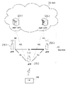
- FIG. 1 is a diagram showing a configuration of a mobile communication system according to an embodiment.
- This mobile communication system conforms to the 5th generation system (5GS: 5th Generation System) of the 3GPP standard.
- 5GS 5th Generation System
- 5GS will be described as an example, but an LTE (Long Term Evolution) system and / or a 6th generation (6G) system may be applied to a mobile communication system at least partially.
- LTE Long Term Evolution
- 6G 6th generation
- mobile communication systems include a user device (UE: User Equipment) 100, a 5G radio access network (NG-RAN: Next Generation Radio Access Network) 10, and a 5G core network (5GC: 5G). It has Core Network) 20.
- UE User Equipment
- NG-RAN Next Generation Radio Access Network
- 5GC 5G core network
- the UE100 is a mobile wireless communication device.
- the UE 100 may be any device as long as it is a device used by the user.
- the UE 100 is a mobile phone terminal (including a smartphone), a tablet terminal, a notebook PC, a communication module (including a communication card or a chipset), a sensor or a device provided in the sensor, a vehicle or a device provided in the vehicle (Vehicle UE). ) And / or a flying object or a device (Aerial UE) provided on the flying object.
- the NG-RAN 10 includes a base station (called “gNB” in a 5G system) 200.
- the gNB 200s are connected to each other via the Xn interface, which is an interface between base stations.
- the gNB 200 manages one or more cells.
- the gNB 200 performs wireless communication with the UE 100 that has established a connection with its own cell.
- the gNB 200 has a radio resource management (RRM) function, a routing function for user data (hereinafter, simply referred to as “data”), and / or a measurement control function for mobility control / scheduling.
- RRM radio resource management
- Cell is used as a term to indicate the smallest unit of a wireless communication area.
- the term “cell” is also used to indicate a function or resource for wireless communication with the UE 100.
- One cell belongs to one carrier frequency.
- gNB can also connect to EPC (Evolved Packet Core), which is the core network of LTE.
- EPC Evolved Packet Core
- LTE base stations can also be connected to 5GC.
- the LTE base station and gNB can also be connected via an inter-base station interface.
- 5GC20 includes AMF (Access and Mobility Management Function) and UPF (User Plane Function) 300.
- the AMF performs various mobility controls and the like for the UE 100.
- the AMF manages the mobility of the UE 100 by communicating with the UE 100 using NAS (Non-Access Stratum) signaling.
- UPF controls data transfer.
- the AMF and UPF are connected to the gNB 200 via the NG interface, which is a base station-core network interface.
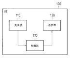
- FIG. 2 is a diagram showing a configuration of a UE 100 (user device) according to an embodiment.
- the UE 100 includes a receiving unit 110, a transmitting unit 120, and a control unit 130.
- the receiving unit 110 performs various receptions under the control of the control unit 130.
- the receiving unit 110 includes an antenna and a receiver.
- the receiver converts the radio signal received by the antenna into a baseband signal (received signal) and outputs it to the control unit 130.
- the transmission unit 120 performs various transmissions under the control of the control unit 130.
- the transmitter 120 includes an antenna and a transmitter.
- the transmitter converts the baseband signal (transmission signal) output by the control unit 130 into a radio signal and transmits it from the antenna.
- the control unit 130 performs various controls on the UE 100.
- the control unit 130 includes at least one processor and at least one memory.
- the memory stores a program executed by the processor and information used for processing by the processor.
- the processor may include a baseband processor and a CPU (Central Processing Unit).
- the baseband processor modulates / demodulates and encodes / decodes the baseband signal.
- the CPU executes a program stored in the memory to perform various processes.
- FIG. 3 is a diagram showing a configuration of gNB200 (base station) according to one embodiment.
- the gNB 200 includes a transmission unit 210, a reception unit 220, a control unit 230, and a backhaul communication unit 240.
- the transmission unit 210 performs various transmissions under the control of the control unit 230.
- the transmitter 210 includes an antenna and a transmitter.
- the transmitter converts the baseband signal (transmission signal) output by the control unit 230 into a radio signal and transmits it from the antenna.
- the receiving unit 220 performs various receptions under the control of the control unit 230.
- the receiving unit 220 includes an antenna and a receiver.
- the receiver converts the radio signal received by the antenna into a baseband signal (received signal) and outputs it to the control unit 230.
- the control unit 230 performs various controls on the gNB 200.
- the control unit 230 includes at least one processor and at least one memory.
- the memory stores a program executed by the processor and information used for processing by the processor.
- the processor may include a baseband processor and a CPU.
- the baseband processor modulates / demodulates and encodes / decodes the baseband signal.
- the CPU executes a program stored in the memory to perform various processes.
- the backhaul communication unit 240 is connected to an adjacent base station via an interface between base stations.
- the backhaul communication unit 240 is connected to the AMF / UPF 300 via the base station-core network interface.
- the gNB is composed of a CU (Central Unit) and a DU (Distributed Unit) (that is, the functions are divided), and both units may be connected by an F1 interface.
- FIG. 4 is a diagram showing a configuration of a protocol stack of a wireless interface of a user plane that handles data.
- the wireless interface protocol of the user plane includes a physical (PHY) layer, a MAC (Medium Access Control) layer, an RLC (Radio Link Control) layer, a PDCP (Packet Data Convergence Protocol) layer, and the like. It has an SDAP (Service Data Application Protocol) layer.
- PHY physical
- MAC Medium Access Control
- RLC Radio Link Control
- PDCP Packet Data Convergence Protocol
- SDAP Service Data Application Protocol
- the PHY layer performs encoding / decoding, modulation / demodulation, antenna mapping / demapping, and resource mapping / demapping. Data and control information are transmitted between the PHY layer of the UE 100 and the PHY layer of the gNB 200 via a physical channel.
- the MAC layer performs data priority control, retransmission processing by hybrid ARQ (Hybrid Automatic Repeat request), random access procedure, and the like. Data and control information are transmitted between the MAC layer of the UE 100 and the MAC layer of the gNB 200 via the transport channel.
- the MAC layer of gNB200 includes a scheduler. The scheduler determines the transport format (transport block size, modulation / coding method (MCS)) of the upper and lower links and the resource block allocated to the UE 100.
- MCS modulation / coding method
- the RLC layer transmits data to the receiving RLC layer by using the functions of the MAC layer and the PHY layer. Data and control information are transmitted between the RLC layer of the UE 100 and the RLC layer of the gNB 200 via a logical channel.
- the PDCP layer performs header compression / decompression and encryption / decryption.
- the SDAP layer maps the IP flow, which is a unit for which the core network performs QoS (Quality of Service) control, with the wireless bearer, which is a unit for which AS (Access Stratum) controls QoS.
- QoS Quality of Service
- AS Access Stratum
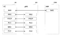
- FIG. 5 is a diagram showing a configuration of a protocol stack of a wireless interface of a control plane that handles signaling (control signal).
- the protocol stack of the radio interface of the control plane has an RRC (Radio Resource Control) layer and a NAS (Non-Access Stratum) layer in place of the SDAP layer shown in FIG.
- RRC signaling for various settings is transmitted between the RRC layer of UE100 and the RRC layer of gNB200.
- the RRC layer controls the logical, transport, and physical channels as the radio bearer is established, reestablished, and released.
- RRC connection connection between the RRC of the UE 100 and the RRC of the gNB 200
- the UE 100 is in the RRC connected state.
- RRC connection no connection between the RRC of the UE 100 and the RRC of the gNB 200
- the UE 100 is in the RRC idle state.
- the connection between the RRC of the UE 100 and the RRC of the gNB 200 is suspended, the UE 100 is in the RRC inactive state.
- the NAS layer located above the RRC layer performs session management, mobility management, etc.
- NAS signaling is transmitted between the NAS layer of the UE 100 and the NAS layer of the AMF300B.
- the UE 100 has an application layer and the like in addition to the wireless interface protocol.
- MBS is a service that enables broadcast or multicast from NG-RAN10 to UE100, that is, one-to-many (PTM: Point To Multipoint) data transmission.
- MBS use cases (service types) are assumed to be public safety communication, mission-critical communication, V2X (Vehicle to Everything) communication, IPv4 or IPv6 multicast distribution, IPTV, group communication, software distribution, and the like.
- the broadcast service provides services to all UEs 100 within a particular service area for applications that do not require highly reliable QoS.
- the MBS session used for the broadcast service is called a broadcast session.
- the multicast service provides the service not to all UE100 but to the group of UE100 participating in the multicast service.
- the MBS session used for the multicast service is called a multicast session. According to the multicast service, the same content can be provided to the group of UE 100 in a wirelessly efficient manner as compared with the broadcast service.
- FIG. 6 is a diagram showing an outline of MBS traffic distribution according to one embodiment.
- MBS traffic is delivered from a single data source (application service provider) to a plurality of UEs.
- the 5G CN (5GC) 20 which is a 5G core network, receives MBS traffic from an application service provider, replicates the MBS traffic, and distributes it.
- 5GC shared MBS traffic distribution (5GC Shared MBS Traffic delivery)
- 5GC individual MBS traffic distribution (5GC Individual MBS Traffic delivery).
- the 5GC20 receives a single copy of MBS data packets and distributes individual copies of those MBS data packets to individual UEs 100 via a PDU (Protocol Data Unit) session for each UE 100. do. Therefore, it is necessary to associate one PDU session with the multicast session for each UE 100.
- PDU Protocol Data Unit
- the 5GC20 receives a single copy of the MBS data packets and delivers the single copy of those MBS packet packets to the RAN node (that is, gNB200).
- the gNB 200 delivers them to one or more UEs 100.
- PTP Point-to-Point
- PTM Point-to-Multipoint
- the gNB 200 wirelessly distributes individual copies of MBS data packets to individual UEs 100.
- the gNB 200 wirelessly distributes a single copy of the MBS data packet to the group of UE 100.
- the gNB 200 dynamically determines whether to use PTM or PTP as a method of delivering MBS traffic to one UE 100.
- the PTP distribution method and the PTM distribution method are mainly related to the user plane.
- As the control mode of MBS traffic distribution there are two distribution modes, a first distribution mode and a second distribution mode.
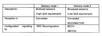
- FIG. 7 is a diagram showing a distribution mode according to one embodiment.
- the first distribution mode (Delivery mode 1) is a distribution mode that can be used by the UE 100 in the RRC connected state, and is a distribution mode for high QoS requirements.
- the first distribution mode is used only for the multicast session among the MBS sessions. In one embodiment, it is assumed that the first delivery mode is used for the multicast session, but the first delivery mode may be used for the broadcast session. In the first distribution mode, the UE 100 in the RRC idle state or the RRC inactive state may also be available.
- the setting of MBS reception in the first distribution mode is performed by dedicated signaling (also referred to as "unicast signaling"). Specifically, the setting of MBS reception in the first distribution mode is performed by the RRC Configuration message (or RRC Release message) which is an RRC message unicast transmitted from the gNB 200 to the UE 100. In the first distribution mode, advanced MBS traffic distribution using the split MBS bearer described later is possible.
- the MBS reception setting includes MBS traffic channel information (hereinafter referred to as "MTCH information") regarding the MBS traffic channel carrying MBS traffic.
- MTCH information includes MBS session information related to the MBS session and scheduling information of the MBS traffic channel corresponding to the MBS session (hereinafter, referred to as “MTCH scheduling information”).
- the MBS traffic channel is a kind of logical channel, and is sometimes called MTCH (Multicast Traffic Channel).
- the MBS traffic channel is mapped to DL-SCH (Downlink Shared Channel), which is a kind of transport channel.
- DL-SCH Downlink Shared Channel
- the second distribution mode (Delivery mode 2) is a distribution mode that can be used not only by the UE 100 in the RRC connected state but also by the UE 100 in the RRC idle state or the RRC inactive state, and is a distribution mode for low QoS requirements. ..
- the second distribution mode is used for the broadcast session among the MBS sessions. However, the second distribution mode may also be applicable to a multicast session.
- MBS reception in the second distribution mode is set by broadcast signaling.
- the setting of MBS reception in the second distribution mode is performed by a logical channel broadcast from the gNB 200 to the UE 100, for example, BCCH (Broadcast Control Channel) or MCCH (Multicast Control Channel).
- BCCH Broadcast Control Channel
- MCCH Multicast Control Channel
- such a control channel may be referred to as an MBS control channel.
- the network can provide different MBS services for each MBS session.
- MBS sessions are identified by at least one of TMGI (Temporary Mobile Group Identity), session identifier, and group RNTI (Radio Network Temporary Identity). At least one of the TMGI and the session identifier is called an MBS session identifier.
- TMGI, session identifier, and group RNTI are collectively referred to as MBS session information.
- the MBS session identifier may be referred to as an MBS service identifier or a multicast group identifier.
- split MBS bearer Next, the split MBS bearer according to the embodiment will be described.
- the split MBS bearer is available in the first delivery mode described above.
- the gNB 200 can set the MBS bearer (hereinafter, appropriately referred to as “split MBS bearer”) separated into the PTP communication path and the PTM communication path in the UE 100.
- the gNB 200 can dynamically switch the transmission of MBS traffic to the UE 100 between the PTP (PTP communication path) and the PTM (PTM communication path).
- the gNB 200 can be made more reliable by using PTP and PTM together to double-transmit the same MBS traffic.
- the gNB 200 can improve reliability by first sending MBS traffic to a plurality of UEs 100 by PTM and retransmitting MBS traffic to a specific UE 100.
- the predetermined layer that terminates the split is a MAC layer (HARQ), an RLC layer, a PDCP layer, or a SDAP layer.
- HARQ MAC layer
- RLC Radio Link Control
- PDCP Packet Control Protocol
- SDAP Secure Sockets Layer
- FIG. 8 is a diagram showing a split MBS bearer according to one embodiment.
- the PTP communication path will be referred to as a PTP leg
- the PTM communication path will be referred to as a PTM leg
- the functional part corresponding to each layer is called an entity.
- each of the PDCP entity of gNB200 and the PDCP entity of UE100 separates the MBS bearer, which is a bearer (data wireless bearer) used for MBS, into a PTP leg and a PTM leg.
- the PDCP entity is provided for each bearer.
- Each of the gNB 200 and the UE 100 has two RLC entities provided for each leg, one MAC entity, and one PHY entity.
- the PHY entity may be provided for each leg.
- the UE 100 may have two MAC entities.
- the PHY entity sends and receives PTP leg data using a cell RNTI (C-RNTI: Cell Radio Network Entity Identifier) that is assigned one-to-one with the UE 100.
- C-RNTI Cell Radio Network Entity Identifier
- G-RNTI Group Radio Network Entity Identifier
- the C-RNTI is different for each UE 100, but the G-RNTI is a common RNTI for a plurality of UEs 100 that receive one MBS session.
- a split MBS bearer is set from gNB200 to UE100, and the PTM leg is activated.
- the gNB 200 cannot perform PTM transmission of MBS traffic using this PTM leg when the PTM leg is in the deactivation state even if the split MBS bearer is set in the UE 100.
- the gNB 200 and the UE 100 perform PTP transmission (unicast) of MBS traffic using the PTP leg.
- the split MBS bearer is set from the gNB 200 to the UE 100 and the PTP leg is activated. There is. In other words, the gNB 200 cannot perform PTP transmission of MBS traffic using this PTP leg when the PTP leg is in the inactive state even if the split MBS bearer is set in the UE 100.
- the UE 100 monitors the PDCCH (Physical Downlink Control Channel) to which the G-RNTI associated with the MBS session is applied while the PTM leg is activated (that is, the blind display of the PDCCH using the G-RNTI). Do the coding).
- the UE 100 may monitor the PDCCH only at the scheduling opportunity of the MBS session.
- the UE 100 does not monitor the G-RNTI-applied PDCCH associated with the MBS session when the PTM leg is deactivated (ie, does not blind decode the PDCCH using the G-RNTI). ..
- the UE 100 monitors the PDCCH to which C-RNTI is applied while the PTP leg is activated.
- the UE 100 monitors the PDCCH in the set on-period (OnDuration) when the intermittent reception (DRX: Display reception) in the PTP leg is set.
- OnDuration on-period
- DRX Display reception
- the UE 100 may monitor the PDCCH of the cell even if the cell is deactivated.
- the UE 100 may monitor the PDCCH to which C-RNTI is applied in preparation for normal unicast downlink transmission other than MBS traffic in a state where the PTP leg is deactivated. However, the UE 100 does not have to monitor the PDCCH for the MBS session when the cell (frequency) associated with the MBS session is specified.
- the split MBS bearer as described above is set by the RRC message (for example, RRC Configuration message) transmitted by the RRC entity of gNB200 to the RRC entity of UE100.
- RRC message for example, RRC Configuration message
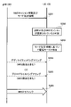
- FIG. 9 is a diagram showing an operation example of the first distribution mode according to the embodiment. In FIG. 9, the non-essential steps are shown by broken lines.
- the UE 100 in the RRC connected state transmits an MBS interest notification (MII: MBS Indication) message to the gNB 200.
- the MII message contains MBS session information about the UE 100's desired MBS session (ie, the MBS session that the UE 100 is interested in receiving).
- the gNB 200 grasps the desired MBS session of the UE 100 by receiving the MII message.
- the MII message is a kind of RRC message.
- the gNB 200 transmits the MBS settings required for receiving the desired MBS session of the UE 100 by decadeted signaling.
- the dedicated signaling is an RRC Reconfiguration message.
- the dedicated signaling may be an RRC Release message.
- step S13 the UE 100 transmits a response message to the dedicated signaling received in step S12 to the gNB 200.
- the response message is, for example, an RRC Configuration Complete message.
- the gNB 200 receives the response message.
- step S14 the gNB 200 transmits MBS traffic by MTCH (for example, multicast transmission) according to the MBS setting set in step S12.
- the gNB 200 may perform advanced MBS traffic distribution using a split MBS bearer.
- the UE 100 receives the MBS traffic.
- FIG. 10 is a diagram showing a configuration example of an RRC Configuration message according to an embodiment.
- the RRC Reconfiguration message transmitted from the gNB 200 to the UE 100 includes the MBS setting required for MBS reception as an information element.
- the MBS setting in the RRC Reconfiguration message includes MTCH information.
- the MBS settings in the RRC Reconnection message may further include RRC connected dedicated settings that are applicable only to MBS reception in the RRC connected state.
- the MTCH information may be a common setting in all RRC states (that is, RRC connected state, RRC idle state, RRC inactive state).
- the MTCH information includes MBS session information (at least one of the MBS session identifier and group RNTI) and MTCH scheduling information.
- the MTCH scheduling information includes at least one of the MTCH transmission occasion and the transmission BWP (Bandwidth Part).
- the group RNTI is a RNTI that is commonly assigned to the group of UE100.
- the transmission occasion is a candidate for the timing (for example, subframe) at which the gNB 200 transmits MBS traffic using the MTCH.
- the transmission BWP is a BWP in which the gNB 200 transmits MBS traffic using the MTCH.
- the BWP is a bandwidth portion narrower than the frequency bandwidth of one cell, and is for limiting the operating bandwidth of the UE 100.
- the RRC connected dedicated settings are the settings related to the split MBS bearer.
- the RRC connected dedicated setting includes, for example, at least one of a split MBS bearer bearer setting, a dynamic switching setting between PTP and PTM, and a PTP leg setting. Since the PTM leg setting can be used even in the RRC idle state or the RRC inactive state, it may be included in the MTCH information.
- the RRC connected-only settings may include HARQ feedback settings.
- FIG. 11 is a diagram showing an operation example of the second distribution mode according to the embodiment.
- the UE 100 may be in any of the RRC states of the RRC connected state, the RRC idle state, and the RRC inactive state.
- the gNB 200 transmits the MBS settings required for MBS reception by broadcast signaling.
- Broadcast signaling is signaling that is periodically transmitted by BCCH and / or MCCH.
- BCCH BCCH
- MCCH MCCH
- step S22 the gNB 200 transmits MBS traffic by MTCH (for example, broadcast transmission) according to the MBS setting set in step S21.
- the UE 100 receives the MBS traffic.
- FIG. 12 is a diagram showing variations of MBS settings in the second distribution mode according to one embodiment.
- the gNB 200 provides the MCU scheduling information to the UE 100 by means of a system information block (SIB) transmitted by the BCCH.
- SIB system information block
- the UE 100 receives the MCCH (ie, MBS setting) based on the SIB received from the gNB 200, and receives the MTCH (ie, MBS traffic) based on the received MCCH.
- MCCH ie, MBS setting
- MTCH ie, MBS traffic
- Such a setting is sometimes called a two-step configuration (Tow-step configuration).
- the gNB 200 may provide the MBS setting to the UE 100 by SIB.
- the UE 100 receives the MTCH (ie, MBS traffic) based on the SIB received from the gNB 200.
- MTCH ie, MBS traffic
- Such a setting is sometimes called a one-step configuration.
- the gNB 200 may configure a plurality of MCCHs (Multiple MCCHs) in one own cell. Each MCCH may have different scheduling (for example, transmission cycle) from each other. Any MCCH may be provided on demand in response to a request from the UE 100.
- MCCHs Multiple MCCHs
- Each MCCH may have different scheduling (for example, transmission cycle) from each other. Any MCCH may be provided on demand in response to a request from the UE 100.
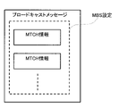
- FIG. 13 is a diagram showing a configuration example of a broadcast message according to one embodiment.
- Broadcast messages correspond to broadcast signaling that provides MBS settings.
- the broadcast message transmitted from the gNB 200 to the UE 100 includes the MBS setting required for MBS reception as an information element.
- the MBS setting in the broadcast message includes one or more MTCH information.
- FIG. 13 shows an example in which a broadcast message includes a plurality of MTCH information corresponding to a plurality of MBS sessions (plurality of MTCHs).
- the UE 100 can receive MBS traffic (that is, MBS reception) in any of the RRC connected state, the RRC idle state, and the RRC inactive state. Further, in the second distribution mode, the UE 100 needs to monitor the broadcast signaling transmitted periodically in order to perform MBS reception.
- MBS traffic that is, MBS reception
- the UE 100 in the RRC connected state tries to receive the MBS traffic delivered in the second delivery mode, it is necessary to interrupt the unicast communication with the gNB 200 and perform periodic monitoring of the broadcast signaling. It is inefficient because it is possible. In addition, there is a concern that the power consumption of the UE 100 will increase.
- the gNB 200 transmits an MBS setting (that is, an MBS setting in the second distribution mode) including at least information necessary for receiving a broadcast session by broadcast signaling.
- the gNB 200 transmits at least a part of the MBS settings to the UE 100 in the RRC connected state by dedicated signaling.
- the MBS setting can be acquired without interrupting the unicast communication with the gNB 200.
- the UE 100 in the RRC connected state performs MBS reception using the MBS setting transmitted by the decadeted signaling without periodically monitoring the broadcast signaling.
- FIG. 14 is a diagram showing an operation example of the first operation pattern according to one embodiment. In FIG. 14, the non-essential steps are shown by broken lines.
- step S101 the gNB 200 periodically transmits the broadcast signaling including the MBS setting.
- the UE 100a in the RRC idle state or the RRC inactive state receives the broadcast signaling.
- step S102 the UE 100b in the RRC connected state transmits a MII message including MBS session information regarding its desired MBS session to the gNB 200.
- the gNB 200 grasps the desired MBS session of the UE 100b by receiving the MII message.
- the UE 100b may establish a session of its own desired MBS session in its upper layer (NAS).
- AMF may establish a tunnel for the MBS session between gNB200 and UPF.
- the gNB 200 transmits the MBS setting required for receiving the desired MBS session of the UE 100b by dedicated signaling (RRC Recognition message).
- the MBS setting transmitted by the gNB 200 by the decadeted signaling is at least a part of the MBS setting transmitted by the gNB 200 by the broadcast signaling.
- the UE 100b receives the MBS setting transmitted by the decadeted signaling. Therefore, the UE 100b does not need to periodically monitor the broadcast signaling.
- the gNB 200 may include the notification information that the broadcast signaling does not need to be monitored in the dedicated signaling and notify the UE 100b.
- the gNB 200 transmits MBS traffic by MTCH (for example, broadcast transmission) according to the MBS setting of the MBS session set in steps S101 and S103.
- UEs 100a and 100b receive MBS traffic.
- the gNB 200 When the gNB 200 changes the MTCH scheduling, the gNB 200 transmits the changed MTCH scheduling information by broadcast signaling. As a result, the gNB 200 updates the MBS setting of the UE 100a. When the gNB 200 changes the MTCH scheduling, the gNB 200 transmits the changed MTCH scheduling information to the UE 100b by decadeted signaling. As a result, the gNB 200 updates the MBS setting of the UE 100b.
- the dedicated signaling may include timing information indicating a predetermined timing for applying the MTCH scheduling information.
- the UE 100b applies (or activates) the MTCH scheduling information at a predetermined timing after receiving the dedicated signaling.
- the predetermined timing may be an absolute time such as a system frame number (SFN), a subframe number and / or a GPS (Global Positioning System) time, and / or a relative time such as a timer threshold.
- SFN system frame number
- GPS Global Positioning System
- the MBS session provided in the first distribution mode for example, a multicast session
- the MBS session provided in the second distribution mode for example, a broadcast session
- the gNB 200 transmits mode designation information for designating one of the first distribution mode and the second distribution mode as the distribution mode related to the MBS to the UE 100.
- the first distribution mode is a distribution mode in which the MBS setting is transmitted from the gNB 200 to the UE 100 by dedicated signaling.
- the second distribution mode is a distribution mode in which the MBS setting is transmitted from the gNB 200 to the UE 100 by broadcast signaling.
- the gNB 200 transmits MBS session information related to the MBS session and mode designation information associated with the MBS session information.
- the UE 100 can appropriately determine whether to receive the desired MBS session in the first distribution mode or the second distribution mode. Specifically, when the UE 100 is interested in receiving the MBS session indicated by the MBS session information received from the gNB 200, the UE 100 receives the MBS setting according to the distribution mode indicated by the mode designation information associated with the MBS session information.
- FIG. 15 is a diagram showing an operation example of the second operation pattern according to one embodiment. In FIG. 15, the non-essential steps are shown by broken lines.
- the gNB 200 transmits the MBS session information regarding the MBS session and the mode designation information associated with the MBS session information to the UE 100.
- the mode designation information may be, for example, 1-bit flag information of "1" in the first distribution mode and "0" in the second distribution mode.
- the mode specification information may be implied. For example, in the first distribution mode, the mode designation information does not exist, and in the second distribution mode, the mode designation information exists. On the contrary, if it is the first mode, the mode designation information may exist, and if it is the second distribution mode, the mode designation information may not exist.
- the mode specification information is information on whether or not the MBS setting can be received by dedicated signaling or whether or not it can be received by broadcast signaling, and / or the UE 100 should receive the MBS setting by which signaling. It may be designated (or selected) information of Kika.
- the set of such MBS session information and mode designation information is transmitted to the UE 100 by any of the SIB, MCCH, and RRC Configuration messages.
- a plurality of sets of MBS session information and mode specification information may be included in one message. That is, the mode designation information may be notified to the UE 100 for each of the plurality of MBS sessions provided by the gNB 200.
- MBS session information and mode designation information can be received by SIB or MCCH.
- the UE 100 can receive the MBS session information and the mode designation information by the SIB, MCCH, or RRC Configuration message.
- step S202 the UE 100 determines whether or not the gNB 200 provides its own desired MBS session based on the MBS session information in the message received in step S201.
- the UE 100 determines that the gNB 200 provides the desired MBS session
- the UE 100 sets the desired MBS session in either the first delivery mode or the second delivery mode based on the mode designation information in the message received in step S201. It is determined whether or not it should be received (step S203).
- the UE 100 When the UE 100 determines that it receives its desired MBS session in the first distribution mode, it receives the MBS setting transmitted from the gNB 200 by dedicated signaling (step S204).
- the UE 100 may notify the gNB 200 of its desired MBS session information in order to prompt the dedicated signaling transmission.
- the notification may be the aforementioned MII.
- the UE 100 determines that it receives its desired MBS session in the second distribution mode, it receives the MBS setting transmitted by broadcast signaling from the gNB 200 (step S205). It is assumed that this broadcast signaling can be received only in the RRC idle state or the RRC inactive state, and the UE 100 is in the RRC connected state. In such a case, the UE 100 transmits a RAI (Releasure Indication) message for transitioning to the RRC idle state or the RRC inactive state to the gNB 200. As a result, the UE 100 may receive the broadcast signaling after transitioning to the RRC idle state or the RRC inactive state.
- RAI Releasure Indication
- step S206 the UE 100 receives the MBS traffic (MTCH) of its desired MBS session based on the MBS setting received from the gNB 200.
- MTCH MBS traffic
- the MBS session provided in the first distribution mode for example, a multicast session
- the MBS session provided in the second distribution mode for example, a broadcast session
- the UE 100 does not know in which distribution mode the gNB 200 provides its desired MBS session.
- the UE 100 first attempts to receive its desired MBS session in the first delivery mode.
- the UE 100 considers that its desired MBS session is provided in the second delivery mode and attempts to receive its desired MBS session in the second delivery mode.
- the UE 100 transmits an MII message including MBS session information regarding its desired MBS session to the gNB 200. After transmitting the MII message, the UE 100 attempts to receive the broadcast signaling including the MBS setting when it is determined that the dedicated signaling including the MBS setting necessary for receiving the desired MBS session is not received from the gNB 200.
- the UE 100 may try to receive the broadcast signaling.
- the UE 100 may attempt to receive the broadcast signaling.
- FIG. 16 is a diagram showing an operation example of the third operation pattern according to one embodiment. In FIG. 16, the non-essential steps are shown by broken lines.
- step S301 the UE 100 in the RRC connected state transmits a MII message including MBS session information regarding its desired MBS session to the gNB 200.
- the gNB 200 grasps the desired MBS session of the UE 100 by receiving the MII message.
- the UE 100 may establish a session of its own desired MBS session in its upper layer (NAS).
- AMF may establish a tunnel for the MBS session between gNB200 and UPF.
- the UE 100 may start a timer for timing a predetermined time in response to the transmission of the MII message.
- This predetermined time (timer value) may be set in advance from the gNB 200 to the UE 100, or may be a predetermined fixed value (for example, 4 wireless frames or the like).
- step S303 the gNB 200 determines that the desired MBS session of the UE 100 is being provided in the second distribution mode.
- the gNB 200 sets the MBS in the first distribution mode to the UE 100 by using the RRC Reconfiguration message.
- the description will proceed on the assumption that it is determined that the desired MBS session is provided in the second distribution mode.
- step S304 the gNB 200 transmits a notification to the UE 100 indicating that the desired MBS session of the UE 100 is being provided in the second distribution mode.
- This notification may be the mode designation information described above.
- step S305 the UE 100 determines that its desired MBS session is provided in the second delivery mode. For example, if the UE 100 does not receive the dedicated signaling from the gNB 200 including the MBS setting required for receiving the desired MBS session within a predetermined time (during the timer operation) after transmitting the MII message, the desired MBS session is the first. 2 Determined to be provided in delivery mode. That is, the UE 100 determines that the desired MBS session is provided in the second delivery mode when the timer expires without receiving the dedicated signaling including the MBS settings required to receive the desired MBS session. Alternatively, the UE 100 may determine that the desired MBS session is provided in the second delivery mode based on the notification in step S304.
- step S306 the UE 100 receives the MBS setting transmitted by broadcast signaling from the gNB 200. It is assumed that this broadcast signaling can be received only in the RRC idle state or the RRC inactive state, and the UE 100 is in the RRC connected state. In such a case, the UE 100 transmits a RAI message for transitioning to the RRC idle state or the RRC inactive state to the gNB 200. As a result, the UE 100 may receive the broadcast signaling after transitioning to the RRC idle state or the RRC inactive state.
- step S307 the UE 100 receives the MBS traffic (MTCH) of its own desired MBS session based on the MBS setting received from the gNB 200 in step S306.
- MBS traffic MTCH
- the MBS session provided in the first distribution mode for example, a multicast session
- the MBS session provided in the second distribution mode for example, a broadcast session
- the UE 100 does not know in which distribution mode the gNB 200 provides its desired MBS session.
- the UE 100 first attempts to receive its desired MBS session in the second distribution mode.
- the UE 100 considers that its desired MBS session is provided in the first delivery mode and attempts to receive its desired MBS session in the first delivery mode.
- the UE 100 attempts to receive broadcast signaling including MBS settings necessary for receiving its desired MBS session.
- the UE 100 does not receive the broadcast signaling including the MBS setting from the gNB 200
- the UE 100 transmits a MII message including the MBS session information regarding the desired MBS session to the gNB 200.
- the gNB 200 can transmit the MBS settings necessary for receiving the desired MBS session to the UE 100 by dedicated signaling in response to the reception of the MII message.
- FIG. 17 is a diagram showing an operation example of the fourth operation pattern according to one embodiment. In FIG. 17, the non-essential steps are shown by broken lines.
- step S401 the UE 100 receives the broadcast signaling including the MBS setting from the gNB 200.
- step S402 the UE 100 determines that its desired MBS session is not provided in the second distribution mode based on the broadcast signaling received in step S401. Specifically, the UE 100 determines that the broadcast signaling received in step S401 does not include the MTCH information corresponding to its desired MBS session.
- the UE 100 transmits an MII message containing MBS session information regarding its desired MBS session to the gNB 200.
- the gNB 200 grasps the desired MBS session of the UE 100 by receiving the MII message.
- the UE 100 may establish a session of its own desired MBS session in its upper layer (NAS).
- AMF may establish a tunnel for the MBS session between gNB200 and UPF.
- the UE 100 When the UE 100 is in the RRC idle state or the RRC inactive state in step S401, the UE 100 performs a random access procedure for transitioning from the RRC idle state or the RRC inactive state to the RRC connected state prior to the step S403. Perform for gNB200.
- the UE 100 may use the message transmitted during this random access procedure (eg, Msg1, MsgA, Msg3, or Msg5) as a MII message to notify the gNB 200 of its desired MBS session.
- step S404 the gNB 200 transmits to the UE 100 dedicated signaling including the MBS settings required to receive the desired MBS session of the UE 100.
- the UE 100 receives the MBS setting by dedicated signaling.
- step S405 the UE 100 receives the MBS traffic (MTCH) of its desired MBS session based on the MBS setting received from the gNB 200 in step S404.
- MTCH MBS traffic
- the gNB 200 may notify the UE 100 that the MBS session will not be provided instead of the MBS setting in step S404.
- the gNB 200 may instruct the UE 100 to receive the MBS session in unicast (PDU session shown in FIG. 6). In this case, the UE 100 attempts to receive the MBS session by the unicast shown in FIG.
- Each of the above-mentioned operation patterns is not limited to the case where they are carried out separately and independently, and some steps of two or more operation patterns can be carried out in combination with each other.
- the base station may be an NR base station (gNB)
- the base station may be an LTE base station (eNB).
- the base station may be a relay node such as an IAB (Integrated Access and Backhaul) node.
- the base station may be a DU (Distributed Unit) of an IAB node.
- a program that causes the computer to execute each process performed by the UE 100 or the gNB 200 may be provided.
- the program may be recorded on a computer-readable medium.
- Computer-readable media can be used to install programs on a computer.
- the computer-readable medium on which the program is recorded may be a non-transient recording medium.
- the non-transient recording medium is not particularly limited, but may be, for example, a recording medium such as a CD-ROM or a DVD-ROM.
- a circuit that executes each process performed by the UE 100 or the gNB 200 may be integrated, and at least a part of the UE 100 or the gNB 200 may be configured as a semiconductor integrated circuit (chipset, SoC).
- MBS Multicast Broadcast Service
- R2 defines the following two modes. 1: Delivery mode for high quality of service (QoS) requirements available in connected (in the absence of data reception, the UE may be able to switch to another state, but undecided). 2: Delivery mode for "low" QoS requirements. The UE can receive data even if it is inactive / idle (details undecided). R2 assumes that delivery mode 1 (in the case of R17) is used only for multicast sessions. R2 assumes that delivery mode 2 is used for the broadcast session. -Further study is required for the applicability of distribution mode 2 to multicast sessions. • No data: The UE may remain RRC connected if there is no data in progress in the multicast session. In other cases, further consideration is needed.
- QoS quality of service
- the UE receives the MBS setting (in the case of broadcast / delivery mode 2) by BCCH and / or MCCH (undecided), which can be received in idle / inactive mode. Connected mode needs further consideration.
- the notification mechanism is used to notify changes in MBS control information.
- control plane of NR MBS will be considered in consideration of the LTE eMBMS mechanism and the latest RAN2 agreement.
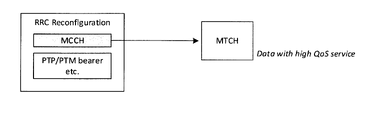
- Distribution mode 1 (Distribution mode 1 setting) Delivery mode 1 is considered primarily for data reception in RRC connected, but configuration aspects have not yet been agreed. While it can be very straightforward for MBS settings to be provided by RRC reconfiguration, it is still under consideration for connected MCCH reception as in LTE eMBMS. Delivery mode 1 should be accompanied by, for example, PTP / PTM split bearers and / or lossless handovers, given the expectations for high QoS services. RRC reconfiguration should be used to configure distribution mode 1 in our view, as it makes no sense if these UE-specific configurations are provided via the MCCH.
- Proposal 1 In delivery mode 1, RAN2 should agree to use RRC reconfiguration for MBS configuration.
- WID clearly shows that RRC connected and idle / inactive should have the greatest commonality with respect to MBS configuration, as follows, while RAN2 for multicast and broadcast sessions respectively. And agreed to different delivery modes.
- the structure of MBS settings and IE should be adjusted as much as possible between the two delivery modes.
- the RRC resetting of the distribution mode 1 includes information unique to the distribution mode 1 such as PTP / PTM split bearer and handover-related information, in addition to MTCH scheduling information which is a block common to the distribution mode 2. Therefore, the details need further examination at this point.
- Proposal 2 From the perspective of MBS configuration, RAN2 should agree to aim for maximum commonality between the two delivery modes, for example using a common structure and IE.
- MCCH in FIG. 18 refers only to MTCH scheduling information, that is, MTCH settings related to MBS session information. In the case of distribution mode 1, adjacent cell information is not required.
- the baseline is that the UE should remain RRC connected for delivery mode 1, a multicast session that requires high QoS.
- other / exceptional cases are still worth considering.
- RAN2 From the perspective of RAN2, it may be beneficial for both the network and the UE to support this feature. It is assumed that when / when the UE is released inactive depends on the implementation of gNB, and whether the UE is released idle depends on the core network. One concern with receiving MBS data at idle is that the gNB releases the UE context. On the other hand, the UE context is retained when it is inactive. This means that the controllability of gNB may be lost, which may contradict the general concept of delivery mode 1. Therefore, RAN2 should agree that distribution mode 1 can be received by the UE at least inactive, but further consideration is needed at idle.
- Proposal 3 In delivery mode 1, RAN2 should agree that delivery mode 1 can be received by the UE at least inactive. Further consideration is needed for idols.
- RRC reconfiguration Idle / inactive UEs continue to apply the MBS configuration provided by the RRC reconfiguration. This option is simple because the UE only reuses the MBS settings originally provided for RRC Connected. However, consider the behavior of some UEs when transitioning to idle / inactive and / or when resuming RRC connected, for example, how to handle PTP / PTM split bearer settings if configured. May need to be done.
- RRC release Idle / inactive UEs apply the MBS settings provided by RRC release. While this option is straightforward, it may not be efficient because it is doubtful whether the MBS settings are different from those previously provided by the RRC reconfiguration.
- -Option 3 Switching the distribution mode from mode 1 to mode 2
- the UE is switched from distribution mode 1 to distribution mode 2 before being released idle / inactive.
- This option is another simple solution, as delivery mode 2 is designed to receive data in all RRC states, as RAN2 agreed. However, it may be expected that packet loss and / or delay will occur during switching, for example due to the acquisition of MCCH.
- RAN2 considers, but is not limited to, the above options, and should discuss how to provide a delivery mode 1 setting for idle / inactive data reception.
- Proposal 4 If Proposal 3 can be agreed, RAN2 should discuss how the delivery mode 1 setting for inactive data reception is provided to the UE.
- the configuration is provided by two messages: SIB20 and SC-MCCH.
- the SIB 20 provides SC-MCCH scheduling information
- the SC-MCCH provides SC-MTCH scheduling information including G-RNTI and TMGI, and adjacent cell information.
- the advantage of the LTE two-stage setting as shown in FIG. 19 is that the SC-MCCH scheduling is independent of the SIB20 scheduling in terms of repetition period, period, change period, and the like. Frequent scheduling / updating of the SC-MCCH has been facilitated, especially for delay-sensitive services and / or UEs that join the session late.
- WID one of the applications is group communication, so the same applies to NR MBS.
- Findings 1 In LTE, a two-step setting using SIB20 and SC-MCCH is useful for different scheduling of these control channels. This is also useful for NR MBS.
- Proposal 5 RAN2 should agree to use a two-step setting with different NR MBS messages, such as SC-PTM SIB20 and SC-MCCH.
- NR MBS is expected to support the various types of use cases described in WID.
- NR MBS is an application that is tolerant of delays such as IoT, from delay-sensitive applications such as mission-critical and V2X, to delay-sensitive applications such as mission-critical and V2X, in addition to other aspects of requirements from lossless applications such as software distribution to UDP-type streaming such as IPTV. It is noticed that it should be properly designed to meet various requirements. Some of these services may be covered by delivery mode 2, but other services with "high QoS requirements" require delivery mode 1. In this sense, it is beneficial for gNB to be able to choose to use delivery mode 2 for multicast sessions.
- RAN2 since RAN2 has already agreed to allow data reception on the RRC connected, it is easy to allow the RRC connected UE to receive the MBS settings. It makes no sense if the UE needs to transition idle / inactive just to get the MCCH. It is easy to allow connected UEs to receive MCCH, but scheduling flexibility (because UEs may need "gap") and / or UE power consumption (UEs are C- It may not be optimal in terms of (because it is necessary to monitor "SC-RNTI" in addition to RNTI and G-RNTI). Therefore, further discussion may be needed as to whether the UE receives MBS settings via MCCH or RRC reconfiguration.
- Proposal 6 RAN2 should agree that delivery mode 2 can be used for multicast sessions in addition to broadcast sessions.
- Proposal 7 In distribution mode 2, RAN2 should agree that the MBS settings can also be received by RRC-connected UEs. Further consideration is required as to whether MCCH or RRC is reset.
- control channel design for distribution mode 2 should consider flexibility and its resource efficiency. Otherwise, for example, if a delay-tolerant service and a delay-sensitive service are configured together on one control channel, the control channel should be configured to meet the delay requirements from the delay-sensitive service. More signaling overhead can be incurred due to frequent scheduling.
- Purpose A of SA2 SI is to enable general MBS services via 5GS, and identified use cases that may benefit from this feature include public safety, mission critical, Includes, but is not limited to, V2X applications, transparent IPv4 / IPv6 multicast distribution, IPTV, software distribution over the air, group communications, and IoT applications.
- Finding 2 The NR MBS control channel for delivery mode 2 is required to be flexible and resource efficient for various types of use cases.
- one MCCH frequently provides delay-sensitive services and another MCCH sparsely provides delay-tolerant services.
- LTE SC-PTM there is a limitation that one cell can have only one SC-MCCH.
- NR MBS distribution mode 2 should remove such restrictions. If multiple MCCHs are allowed in the cell, each MCCH has different scheduling settings, such as repeat periods, that can be optimized for a particular service. Further consideration is needed on how the UE identifies the MCCH that provides the service of interest.
- Proposal 8 In delivery mode 2, RAN2 should discuss whether the cell supports multiple MCCHs, which was not in LTE.
- the new paradigm of NR is support for on-demand SI transmission.
- This concept can be reused for MCCH in delivery mode 2, ie on-demand MCCH.
- delay-tolerant MCCHs for services are provided on demand, which can optimize signaling resource consumption.
- the network has another option to provide MCCH on a regular basis, i.e., for services that are sensitive to delays rather than on-demand.
- Proposal 9 In delivery mode 2, RAN2 should discuss options when MCCH is provided on demand, which was not in LTE.
- the SIB provides MTCH scheduling information directly, i.e. without MCCH. This will provide optimizations for delay-tolerant services and / or power-sensitive UEs.
- the UE may request an SIB (on-demand), and the gNB may start providing the SIB and the corresponding service after the request from the plurality of UEs. These UEs do not need to monitor the repeatedly broadcast MCCH.
- Proposal 10 In distribution mode 2, RAN2 should discuss options such as SIB providing MTCH scheduling information directly when multicast reception without MCCH (ie, one-step configuration) is supported.
- MII MBMS Interest Indications
- MBMS MBMS Interest Indications
- MBMS MBMS Interest Indications
- Counting was specified.
- the UE-triggered MII contains information related to the MBMS frequency of interest, the MBMS service of interest, the MBMS priority, and the MBMS ROM (receive-only mode).
- the counting response triggered by the network through the counting request of a particular MBMS service contains information related to the MBSFN area of interest and the MBMS service.
- MII is primarily used in networks to ensure that UEs can continue to receive services of interest during the connected state.
- Counting is used to allow the network to determine if a sufficient number of UEs are interested in receiving the service.
- Finding 3 In LTE e MBMS, two types of UE assistance information are introduced for different purposes. That is, MBMS interest indication is introduced for NB scheduling, and MBMS counting is introduced for MCE session control.
- Rel-17 does not require MII MBMS ROM information and information about the counting response MBSFN area, as ROM and SFN are not supported as described in the WID.
- Proposal 11 RAN2 needs to agree to introduce UE assistance information for NR MBS, such as MBS interest indications and / or MBS counting.
- LTE eMBMS neither MII nor counting can collect information from idle UEs, even if most of the UEs are receiving broadcast services in the RRC idle state. This is, in our understanding, one of the remaining problems with LTE eMBMS in terms of session control and resource efficiency.
- the same problem may exist in UEs in the idle / inactive state.
- the network does not know if an idle / inactive UE is not receiving / interested in broadcast services. Therefore, the network may continue to provide PTM transmissions even if no UE is being serviced. Such unnecessary PTMs should be avoided if the gNB is aware of the interests of the idle / inactive UE. Conversely, if the PTM goes down while there are still idle / inactive UEs receiving service, many UEs may request a connection at the same time. This is also undesirable.
- Proposal 12 RAN2 needs to consider whether UE assistance information such as MBS counting is also collected from the idle / inactive UE.
Landscapes
- Engineering & Computer Science (AREA)
- Computer Networks & Wireless Communication (AREA)
- Signal Processing (AREA)
- Multimedia (AREA)
- Mobile Radio Communication Systems (AREA)
Priority Applications (3)
| Application Number | Priority Date | Filing Date | Title |
|---|---|---|---|
| JP2022575592A JP7813727B2 (ja) | 2021-01-12 | 2022-01-12 | 通信制御方法 |
| US18/350,599 US20230354475A1 (en) | 2021-01-12 | 2023-07-11 | Communication control method |
| JP2025180365A JP2026016596A (ja) | 2021-01-12 | 2025-10-27 | 通信制御方法、基地局、プログラム、プロセッサ、ユーザ装置及び移動通信システム |
Applications Claiming Priority (2)
| Application Number | Priority Date | Filing Date | Title |
|---|---|---|---|
| US202163136486P | 2021-01-12 | 2021-01-12 | |
| US63/136,486 | 2021-01-12 |
Related Child Applications (1)
| Application Number | Title | Priority Date | Filing Date |
|---|---|---|---|
| US18/350,599 Continuation US20230354475A1 (en) | 2021-01-12 | 2023-07-11 | Communication control method |
Publications (1)
| Publication Number | Publication Date |
|---|---|
| WO2022153991A1 true WO2022153991A1 (ja) | 2022-07-21 |
Family
ID=82446721
Family Applications (1)
| Application Number | Title | Priority Date | Filing Date |
|---|---|---|---|
| PCT/JP2022/000642 Ceased WO2022153991A1 (ja) | 2021-01-12 | 2022-01-12 | 通信制御方法 |
Country Status (3)
| Country | Link |
|---|---|
| US (1) | US20230354475A1 (https=) |
| JP (2) | JP7813727B2 (https=) |
| WO (1) | WO2022153991A1 (https=) |
Cited By (4)
| Publication number | Priority date | Publication date | Assignee | Title |
|---|---|---|---|---|
| JPWO2024034567A1 (https=) * | 2022-08-09 | 2024-02-15 | ||
| JP2024046772A (ja) * | 2022-09-26 | 2024-04-05 | シャープ株式会社 | 基地局装置、端末装置、及び通信方法 |
| WO2024082295A1 (zh) * | 2022-10-21 | 2024-04-25 | 北京小米移动软件有限公司 | 小区处理、小区处理指示方法和装置 |
| WO2024162425A1 (ja) * | 2023-02-03 | 2024-08-08 | 京セラ株式会社 | 通信方法 |
Families Citing this family (1)
| Publication number | Priority date | Publication date | Assignee | Title |
|---|---|---|---|---|
| KR20240128662A (ko) * | 2021-12-27 | 2024-08-26 | 삼성전자주식회사 | 무선 통신 시스템에서 mbs 서비스에 대한 ue 능력 및 지원 시그널링을 위한 방법 및 장치 |
Citations (1)
| Publication number | Priority date | Publication date | Assignee | Title |
|---|---|---|---|---|
| EP3349487A1 (en) * | 2017-01-12 | 2018-07-18 | ASUSTek Computer Inc. | Method and apparatus of handling interest indication in a wireless communication system |
-
2022
- 2022-01-12 JP JP2022575592A patent/JP7813727B2/ja active Active
- 2022-01-12 WO PCT/JP2022/000642 patent/WO2022153991A1/ja not_active Ceased
-
2023
- 2023-07-11 US US18/350,599 patent/US20230354475A1/en active Pending
-
2025
- 2025-10-27 JP JP2025180365A patent/JP2026016596A/ja active Pending
Patent Citations (1)
| Publication number | Priority date | Publication date | Assignee | Title |
|---|---|---|---|---|
| EP3349487A1 (en) * | 2017-01-12 | 2018-07-18 | ASUSTek Computer Inc. | Method and apparatus of handling interest indication in a wireless communication system |
Non-Patent Citations (4)
| Title |
|---|
| CATT, CBN: "Further Discussion on MBS Idle Mode Support", 3GPP DRAFT; R2-2008797, 3RD GENERATION PARTNERSHIP PROJECT (3GPP), MOBILE COMPETENCE CENTRE ; 650, ROUTE DES LUCIOLES ; F-06921 SOPHIA-ANTIPOLIS CEDEX ; FRANCE, vol. RAN WG2, no. Electronic meeting; 20201102 - 20201113, 23 October 2020 (2020-10-23), Mobile Competence Centre ; 650, route des Lucioles ; F-06921 Sophia-Antipolis Cedex ; France , XP051941903 * |
| INTEL CORPORATION: "MBS L2 Architecture, user plane and control plane", 3GPP DRAFT; R2-2009196, 3RD GENERATION PARTNERSHIP PROJECT (3GPP), MOBILE COMPETENCE CENTRE ; 650, ROUTE DES LUCIOLES ; F-06921 SOPHIA-ANTIPOLIS CEDEX ; FRANCE, vol. RAN WG2, no. Electronic meeting; 20201102 - 20201113, 23 October 2020 (2020-10-23), Mobile Competence Centre ; 650, route des Lucioles ; F-06921 Sophia-Antipolis Cedex ; France , XP051942203 * |
| KYOCERA: "Consideration of control plane aspects for NR MBS", 3GPP DRAFT; R2-2010234, 3RD GENERATION PARTNERSHIP PROJECT (3GPP), MOBILE COMPETENCE CENTRE ; 650, ROUTE DES LUCIOLES ; F-06921 SOPHIA-ANTIPOLIS CEDEX ; FRANCE, vol. RAN WG2, no. Online; 20201102 - 20201113, 23 October 2020 (2020-10-23), Mobile Competence Centre ; 650, route des Lucioles ; F-06921 Sophia-Antipolis Cedex ; France , XP051942914 * |
| KYOCERA: "Further consideration of control plane aspects for NR MBS", 3GPP DRAFT; R2-2100803, 3RD GENERATION PARTNERSHIP PROJECT (3GPP), MOBILE COMPETENCE CENTRE ; 650, ROUTE DES LUCIOLES ; F-06921 SOPHIA-ANTIPOLIS CEDEX ; FRANCE, vol. RAN WG2, no. Online; 20210125 - 20210205, 14 January 2021 (2021-01-14), Mobile Competence Centre ; 650, route des Lucioles ; F-06921 Sophia-Antipolis Cedex ; France , XP051972724 * |
Cited By (6)
| Publication number | Priority date | Publication date | Assignee | Title |
|---|---|---|---|---|
| JPWO2024034567A1 (https=) * | 2022-08-09 | 2024-02-15 | ||
| WO2024034567A1 (ja) * | 2022-08-09 | 2024-02-15 | 京セラ株式会社 | 通信方法 |
| JP2024046772A (ja) * | 2022-09-26 | 2024-04-05 | シャープ株式会社 | 基地局装置、端末装置、及び通信方法 |
| WO2024082295A1 (zh) * | 2022-10-21 | 2024-04-25 | 北京小米移动软件有限公司 | 小区处理、小区处理指示方法和装置 |
| WO2024162425A1 (ja) * | 2023-02-03 | 2024-08-08 | 京セラ株式会社 | 通信方法 |
| JPWO2024162425A1 (https=) * | 2023-02-03 | 2024-08-08 |
Also Published As
| Publication number | Publication date |
|---|---|
| US20230354475A1 (en) | 2023-11-02 |
| JP7813727B2 (ja) | 2026-02-13 |
| JPWO2022153991A1 (https=) | 2022-07-21 |
| JP2026016596A (ja) | 2026-02-03 |
Similar Documents
| Publication | Publication Date | Title |
|---|---|---|
| US20230262423A1 (en) | Communication control method | |
| US20230354465A1 (en) | Communication control method and user equipment | |
| US20240080939A1 (en) | Communication control method and user equipment | |
| JP7813727B2 (ja) | 通信制御方法 | |
| US12389205B2 (en) | Communication control method and user equipment | |
| WO2022085717A1 (ja) | 通信制御方法 | |
| WO2022025013A1 (ja) | 通信制御方法 | |
| WO2022030452A1 (ja) | 通信制御方法、基地局、及びユーザ装置 | |
| US20240080940A1 (en) | Communication control method | |
| US20240080645A1 (en) | Communication control method | |
| US20230261970A1 (en) | Communication control method | |
| WO2023013605A1 (ja) | 通信方法、ネットワーク装置、及びユーザ装置 | |
| US20240179798A1 (en) | Communication method | |
| JP2024123238A (ja) | 通信制御方法、ユーザ装置、プロセッサ、プログラム及び移動通信システム | |
| JP2026010095A (ja) | 通信制御方法、ユーザ装置、プロセッサ、プログラム、及び移動通信システム | |
| US20240237143A1 (en) | Communication method | |
| US20240022447A1 (en) | Communication control method and user equipment | |
| US20240284555A1 (en) | Communication method and user equipment | |
| WO2022085644A1 (ja) | 通信制御方法 |
Legal Events
| Date | Code | Title | Description |
|---|---|---|---|
| 121 | Ep: the epo has been informed by wipo that ep was designated in this application |
Ref document number: 22739397 Country of ref document: EP Kind code of ref document: A1 |
|
| ENP | Entry into the national phase |
Ref document number: 2022575592 Country of ref document: JP Kind code of ref document: A |
|
| NENP | Non-entry into the national phase |
Ref country code: DE |
|
| 122 | Ep: pct application non-entry in european phase |
Ref document number: 22739397 Country of ref document: EP Kind code of ref document: A1 |