WO2022030452A1 - 通信制御方法、基地局、及びユーザ装置 - Google Patents
通信制御方法、基地局、及びユーザ装置 Download PDFInfo
- Publication number
- WO2022030452A1 WO2022030452A1 PCT/JP2021/028635 JP2021028635W WO2022030452A1 WO 2022030452 A1 WO2022030452 A1 WO 2022030452A1 JP 2021028635 W JP2021028635 W JP 2021028635W WO 2022030452 A1 WO2022030452 A1 WO 2022030452A1
- Authority
- WO
- WIPO (PCT)
- Prior art keywords
- mbs
- cell
- control
- control area
- information
- Prior art date
Links
- 238000000034 method Methods 0.000 title claims abstract description 43
- 238000004891 communication Methods 0.000 title claims abstract description 34
- 238000010295 mobile communication Methods 0.000 claims abstract description 22
- 230000005540 biological transmission Effects 0.000 claims description 72
- 238000005259 measurement Methods 0.000 claims description 23
- 230000008569 process Effects 0.000 claims description 15
- 230000004044 response Effects 0.000 claims description 15
- 238000012545 processing Methods 0.000 claims description 5
- 230000006870 function Effects 0.000 description 25
- 230000004048 modification Effects 0.000 description 25
- 238000012986 modification Methods 0.000 description 25
- 230000008859 change Effects 0.000 description 17
- 101150014328 RAN2 gene Proteins 0.000 description 13
- 238000010586 diagram Methods 0.000 description 13
- 230000011664 signaling Effects 0.000 description 9
- 230000007246 mechanism Effects 0.000 description 7
- 238000013461 design Methods 0.000 description 6
- 238000013507 mapping Methods 0.000 description 6
- 238000012384 transportation and delivery Methods 0.000 description 5
- 238000007726 management method Methods 0.000 description 4
- 230000008901 benefit Effects 0.000 description 3
- 238000005516 engineering process Methods 0.000 description 3
- 230000007704 transition Effects 0.000 description 3
- 101000741965 Homo sapiens Inactive tyrosine-protein kinase PRAG1 Proteins 0.000 description 2
- 102100038659 Inactive tyrosine-protein kinase PRAG1 Human genes 0.000 description 2
- 230000006835 compression Effects 0.000 description 2
- 238000007906 compression Methods 0.000 description 2
- 230000007774 longterm Effects 0.000 description 2
- 238000012546 transfer Methods 0.000 description 2
- 230000001052 transient effect Effects 0.000 description 2
- 230000001960 triggered effect Effects 0.000 description 2
- 101001018494 Homo sapiens Pro-MCH Proteins 0.000 description 1
- 102100033721 Pro-MCH Human genes 0.000 description 1
- 101150069124 RAN1 gene Proteins 0.000 description 1
- 101100355633 Salmo salar ran gene Proteins 0.000 description 1
- 230000009471 action Effects 0.000 description 1
- 230000006837 decompression Effects 0.000 description 1
- 230000001934 delay Effects 0.000 description 1
- 238000005457 optimization Methods 0.000 description 1
- 238000013468 resource allocation Methods 0.000 description 1
- 239000004065 semiconductor Substances 0.000 description 1
- 230000001360 synchronised effect Effects 0.000 description 1
Images


Classifications
-
- H—ELECTRICITY
- H04—ELECTRIC COMMUNICATION TECHNIQUE
- H04W—WIRELESS COMMUNICATION NETWORKS
- H04W72/00—Local resource management
- H04W72/30—Resource management for broadcast services
-
- H—ELECTRICITY
- H04—ELECTRIC COMMUNICATION TECHNIQUE
- H04W—WIRELESS COMMUNICATION NETWORKS
- H04W4/00—Services specially adapted for wireless communication networks; Facilities therefor
- H04W4/06—Selective distribution of broadcast services, e.g. multimedia broadcast multicast service [MBMS]; Services to user groups; One-way selective calling services
-
- H—ELECTRICITY
- H04—ELECTRIC COMMUNICATION TECHNIQUE
- H04W—WIRELESS COMMUNICATION NETWORKS
- H04W36/00—Hand-off or reselection arrangements
- H04W36/0005—Control or signalling for completing the hand-off
- H04W36/0007—Control or signalling for completing the hand-off for multicast or broadcast services, e.g. MBMS
-
- H—ELECTRICITY
- H04—ELECTRIC COMMUNICATION TECHNIQUE
- H04W—WIRELESS COMMUNICATION NETWORKS
- H04W48/00—Access restriction; Network selection; Access point selection
- H04W48/08—Access restriction or access information delivery, e.g. discovery data delivery
- H04W48/12—Access restriction or access information delivery, e.g. discovery data delivery using downlink control channel
-
- H—ELECTRICITY
- H04—ELECTRIC COMMUNICATION TECHNIQUE
- H04W—WIRELESS COMMUNICATION NETWORKS
- H04W48/00—Access restriction; Network selection; Access point selection
- H04W48/20—Selecting an access point
-
- H—ELECTRICITY
- H04—ELECTRIC COMMUNICATION TECHNIQUE
- H04W—WIRELESS COMMUNICATION NETWORKS
- H04W74/00—Wireless channel access
- H04W74/08—Non-scheduled access, e.g. ALOHA
- H04W74/0833—Random access procedures, e.g. with 4-step access
Definitions
- the present invention relates to a communication control method, a base station, and a user device used in a mobile communication system.
- NR New Radio
- RAT Radio Access Technology
- LTE Long Term Evolution
- the communication control method is a communication control method used in a mobile communication system that provides a multicast / broadcast service (MBS) from a base station to a user apparatus, and the base station that manages a cell is a communication control method. It is an area range to which the MBS control information used for receiving the MBS data is transmitted to the user apparatus and the base station can apply at least a part of the MBS control information via the MBS control channel of the cell. It includes transmitting a control area identifier indicating an MBS control area range to the user apparatus.
- MBS multicast / broadcast service
- the base station is a base station used in a mobile communication system that provides a multicast broadcast service (MBS), and is used for receiving MBS data via the MBS control channel of the cell of the base station.
- MBS multicast broadcast service
- the user device is a user device used in a mobile communication system that provides a multicast broadcast service (MBS), and MBS control information used for receiving MBS data via the MBS control channel of the cell is used.
- MBS multicast broadcast service
- It has a processor that executes a process of storing a control area identifier and a process of receiving the MBS data based on the stored MBS control information within the MBS control area range indicated by the stored control area identifier.
- NR 5G system
- the purpose of this disclosure is to realize an improved multicast / broadcast service.
- FIG. 1 is a diagram showing a configuration of a mobile communication system according to an embodiment.
- This mobile communication system complies with the 5th generation system (5GS: 5th Generation System) of the 3GPP standard.
- 5GS 5th Generation System
- 5GS will be described as an example, but an LTE (Long Term Evolution) system may be applied to a mobile communication system at least partially.
- mobile communication systems include a user device (UE: User Equipment) 100, a 5G radio access network (NG-RAN: Next Generation Radio Access Network) 10, and a 5G core network (5GC: 5G). It has Core Network) 20.
- UE User Equipment
- NG-RAN Next Generation Radio Access Network
- 5GC 5G core network
- the UE 100 is a mobile wireless communication device.
- the UE 100 may be any device as long as it is a device used by the user.
- the UE 100 may be a mobile phone terminal (including a smartphone), a tablet terminal, a notebook PC, or a communication module (communication card or communication card). (Including a chip set), a sensor or a device provided on the sensor, a vehicle or a device provided on the vehicle (Vehicle UE), a vehicle or a device provided on the vehicle (Arial UE).
- the NG-RAN 10 includes a base station (referred to as "gNB” in a 5G system) 200.
- the gNB 200 are connected to each other via the Xn interface, which is an interface between base stations.
- the gNB 200 manages one or more cells.
- the gNB 200 performs wireless communication with the UE 100 that has established a connection with its own cell.
- the gNB 200 has a radio resource management (RRM) function, a routing function for user data (hereinafter, simply referred to as “data”), a measurement control function for mobility control / scheduling, and the like.
- RRM radio resource management
- Cell is used as a term to indicate the smallest unit of a wireless communication area.
- the term “cell” is also used to indicate a function or resource for wireless communication with the UE 100.
- One cell belongs to one carrier frequency.
- gNB can also connect to EPC (Evolved Packet Core), which is the core network of LTE.
- EPC Evolved Packet Core
- LTE base stations can also be connected to 5GC.
- the LTE base station and gNB can also be connected via an inter-base station interface.
- 5GC20 includes AMF (Access and Mobility Management Function) and UPF (User Plane Function) 300.
- the AMF performs various mobility controls and the like for the UE 100.
- the AMF manages the mobility of the UE 100 by communicating with the UE 100 using NAS (Non-Access Stratum) signaling.
- UPF controls data transfer.
- the AMF and UPF are connected to the gNB 200 via the NG interface, which is an interface between the base station and the core network.
- FIG. 2 is a diagram showing a configuration of a UE 100 (user device) according to an embodiment.
- the UE 100 includes a receiving unit 110, a transmitting unit 120, and a control unit 130.
- the receiving unit 110 performs various receptions under the control of the control unit 130.
- the receiving unit 110 includes an antenna and a receiver.
- the receiver converts the radio signal received by the antenna into a baseband signal (received signal) and outputs it to the control unit 130.
- the transmission unit 120 performs various transmissions under the control of the control unit 130.
- the transmitter 120 includes an antenna and a transmitter.
- the transmitter converts the baseband signal (transmission signal) output by the control unit 130 into a radio signal and transmits it from the antenna.
- the control unit 130 performs various controls on the UE 100.
- the control unit 130 includes at least one processor and at least one memory.
- the memory stores a program executed by the processor and information used for processing by the processor.
- the processor may include a baseband processor and a CPU (Central Processing Unit).
- the baseband processor modulates / demodulates and encodes / decodes the baseband signal.
- the CPU executes a program stored in the memory to perform various processes.
- FIG. 3 is a diagram showing the configuration of the gNB 200 (base station) according to the embodiment.
- the gNB 200 includes a transmission unit 210, a reception unit 220, a control unit 230, and a backhaul communication unit 240.
- the transmission unit 210 performs various transmissions under the control of the control unit 230.
- the transmitter 210 includes an antenna and a transmitter.
- the transmitter converts the baseband signal (transmission signal) output by the control unit 230 into a radio signal and transmits it from the antenna.
- the receiving unit 220 performs various receptions under the control of the control unit 230.
- the receiving unit 220 includes an antenna and a receiver.
- the receiver converts the radio signal received by the antenna into a baseband signal (received signal) and outputs it to the control unit 230.
- the control unit 230 performs various controls on the gNB 200.
- the control unit 230 includes at least one processor and at least one memory.
- the memory stores a program executed by the processor and information used for processing by the processor.
- the processor may include a baseband processor and a CPU.
- the baseband processor modulates / demodulates and encodes / decodes the baseband signal.
- the CPU executes a program stored in the memory to perform various processes.
- the backhaul communication unit 240 is connected to an adjacent base station via an interface between base stations.
- the backhaul communication unit 240 is connected to the AMF / UPF 300 via the base station-core network interface.
- the gNB is composed of a CU (Central Unit) and a DU (Distributed Unit) (that is, the functions are divided), and both units may be connected by an F1 interface.
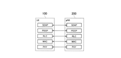
- FIG. 4 is a diagram showing a configuration of a protocol stack of a wireless interface of a user plane that handles data.
- the wireless interface protocol of the user plane includes a physical (PHY) layer, a MAC (Medium Access Control) layer, an RLC (Radio Link Control) layer, and a PDCP (Packet Data Convergence Protocol) layer. It has an SDAP (Service Data Adjustment Protocol) layer.
- PHY physical
- MAC Medium Access Control
- RLC Radio Link Control
- PDCP Packet Data Convergence Protocol
- SDAP Service Data Adjustment Protocol
- the PHY layer performs coding / decoding, modulation / demodulation, antenna mapping / demapping, and resource mapping / demapping. Data and control information are transmitted between the PHY layer of the UE 100 and the PHY layer of the gNB 200 via a physical channel.
- the MAC layer performs data priority control, retransmission processing by hybrid ARQ (HARQ), random access procedure, and the like. Data and control information are transmitted between the MAC layer of the UE 100 and the MAC layer of the gNB 200 via the transport channel.
- the MAC layer of gNB200 includes a scheduler. The scheduler determines the transport format (transport block size, modulation / coding method (MCS)) of the upper and lower links and the resource block allocated to the UE 100.
- MCS modulation / coding method
- the RLC layer transmits data to the receiving RLC layer by using the functions of the MAC layer and the PHY layer. Data and control information are transmitted between the RLC layer of the UE 100 and the RLC layer of the gNB 200 via a logical channel.
- the PDCP layer performs header compression / decompression and encryption / decryption.
- the SDAP layer maps the IP flow, which is a unit for performing QoS control by the core network, with the wireless bearer, which is a unit for performing QoS control by AS (Access Stratum).
- AS Access Stratum
- FIG. 5 is a diagram showing a configuration of a protocol stack of a wireless interface of a control plane that handles signaling (control signal).
- the protocol stack of the radio interface of the control plane has an RRC (Radio Resource Control) layer and a NAS (Non-Access Stratum) layer in place of the SDAP layer shown in FIG.
- RRC signaling for various settings is transmitted between the RRC layer of UE100 and the RRC layer of gNB200.
- the RRC layer controls logical channels, transport channels, and physical channels in response to the establishment, re-establishment, and release of radio bearers.
- RRC connection connection between the RRC of the UE 100 and the RRC of the gNB 200
- the UE 100 is in the RRC connected state.
- RRC connection no connection between the RRC of the UE 100 and the RRC of the gNB 200
- the UE 100 is in the RRC idle state.
- the connection between the RRC of the UE 100 and the RRC of the gNB 200 is suspended, the UE 100 is in the RRC inactive state.
- the NAS layer located above the RRC layer performs session management, mobility management, etc.
- NAS signaling is transmitted between the NAS layer of the UE 100 and the NAS layer of the AMF300.
- the UE 100 has an application layer and the like in addition to the wireless interface protocol.
- MBS is a service that broadcasts or multicasts data from NG-RAN10 to UE100, that is, one-to-many (PTM: Point To Multipoint) data transmission.
- PTM Point To Multipoint
- MBS may be referred to as MBMS (Multicast Broadcast and Multicast Service).
- the MBS use cases (service types) include public safety communication, mission-critical communication, V2X (Vehicle to Everything) communication, IPv4 or IPv6 multicast distribution, IPTV, group communication, software distribution, and the like.
- FIG. 6 is a diagram showing the correspondence between the downlink logical channel (Logical channel) and the transport channel (Transport channel) according to the embodiment.
- the logical channels used for MBSFN transmission are MTCH (Multicast Traffic Channel) and MCCH (Multicast Control Channel), and the transport channel used for MBSFN transmission is MCH (Multicast Control Channel).
- MBSFN transmission is mainly designed for multi-cell transmission, and each cell performs synchronous transmission of the same signal (same data) in the same MBSFN subframe in an MBSFN area composed of a plurality of cells.
- SC-PTM transmission The logical channels used for SC-PTM transmission are SC-MTCH (Single Cell Multicast Traffic Channel) and SC-MCCH (Single Cell Multicast Control Channel), and the transport channels used for SC-PTM transmission are DL-SCH (Downlink). ).
- SC-PTM transmission is designed primarily for single-cell transmission and performs broadcast or multicast data transmission on a cell-by-cell basis.
- the physical channels used for SC-PTM transmission are PDCCH (Physical Downlink Control Channel) and PDSCH (Physical Downlink Control Channel), and dynamic resource allocation is possible.
- MBS may be provided using the SC-PTM transmission method.
- MBS may be provided using the MBSFN transmission method.
- MBS may be read as multicast.
- MBS may be provided by broadcast.
- MBS data means data transmitted by MBS.
- the MBS control channel refers to MCCH or SC-MCCH
- the MBS traffic channel refers to MTCH or SC-MTCH.
- the network can provide different MBS services for each MBS session.
- the MBS service is identified by at least one of TMGI (Temporary Mobile Group Identity) and a session identifier, and at least one of these identifiers is called an MBS service identifier.
- TMGI Temporary Mobile Group Identity
- Such an MBS service identifier may be referred to as an MBS session identifier or a multicast group identifier.
- the UE 100 that receives MBS can move across cells. In order for such a UE 100 to continue MBS reception, it is necessary to receive the MBS control channel (MBS control information) at least at the time of cell switching in the switching destination cell. Therefore, there is a problem that the load and power consumption of the UE 100 increase and it is difficult to promptly receive MBS data from the switching destination cell.
- MBS control information MBS control information
- control area function a function that allows MBS control information to be shared within an area range consisting of a plurality of cells.
- MBS control area range an area range consisting of a plurality of cells
- the gNB 200 transmits the MBS control information used for receiving the MBS data to the UE 100 via the MBS control channel of the own cell.
- the gNB 200 transmits to the UE 100 a control area identifier indicating an MBS control area range, which is an area range to which at least a part of the MBS control information can be applied.
- the UE 100 can grasp the MBS control area range in which the MBS control information of the current cell can be reused.
- the UE 100 stores the MBS control information and the control area identifier from the gNB 200. Then, the UE 100 receives MBS data based on the stored MBS control information within the MBS control area range indicated by the stored control area identifier. In this way, MBS data can be received by using MBS control information even across cells within the stored area range, so that the load and power consumption of the UE 100 can be suppressed, and MBS data can be quickly received from the switching destination cell. It will be easier to do.
- FIG. 7 is a diagram showing the operation of the mobile communication system according to the embodiment.
- step S1 the gNB 200 that manages the cell C1 transmits MBS system information to the UE 100 via the broadcast control channel (BCCH: Broadcast Control Channel) of the cell C1.
- the transmission of MBS system information is performed by broadcasting using a predetermined RNTI (Radio Network Temporary Identifier).
- the UE 100 receives the MBS system information.
- the system information may be called SIB (System Information Block).
- MBS system information includes scheduling information necessary for receiving the MBS control channel.
- the MBS system information includes information indicating a cycle in which the contents of the MBS control channel (MBS control information) can be changed, information indicating the time interval of MBS control channel transmission in terms of the number of radio frames, and the MBS control channel being scheduled. It contains at least one of information indicating the offset of the radio frame and information indicating the subframe to which the MBS control channel is scheduled.
- the MBS system information further includes MBS control area settings.
- the MBS control area setting includes an information element (hereinafter, referred to as “applicability flag”) indicating whether or not the cell C1 can apply the control area function. If cell C1 is applicable to the control area function, the MBS system information includes the control area identifier. However, when the MBS system information exists, it is implicitly considered that the control area function can be applied, and the applicability flag does not have to exist.
- the MBS control area setting may include expiration date information (for example, valid until a certain wireless frame, valid until a certain time, valid within a certain time) indicating a period during which this MBS control area setting is valid.
- expiration date information for example, valid until a certain wireless frame, valid until a certain time, valid within a certain time
- the adjacent cells constituting the MBS control area range may change their own MBS control information. Such changes may be made by the operator's equipment, by the core network, or by signaling between gNB200.
- control area function may be restricted to be enabled only when the SFN (Single Frequency Network) is configured by a plurality of cells including the cell C1.
- SFN refers to a network in which a plurality of cells operated at the same frequency transmit the same signal at the same time.
- the UE 100 receives signals (combined signals) from the plurality of cells without identifying which cell the signal was transmitted from.
- the control area function may be enabled for the MBS control channel for configuring the SFN.
- control area identifier may be shared with the system information area identifier indicating the system information area range.
- the system information area range means an area range in which MBS system information can be reused.
- the MBS system information may include information indicating that the MBS control information conforms to the setting of the area range of the MBS system information. That is, this information is information indicating that the system information area identifier is handled as the control area identifier.
- the MBS system information may include an MBS control area setting for each MBS control channel.
- the MBS system information may include an MBS service identifier and / or an MBS control channel identifier and an MBS control area setting associated with this identifier.
- the network slice identifier associated with the MBS control channel may be included in the MBS system information.
- the UE 100 grasps the scheduling of the MBS control channel based on the MBS system information received from the gNB 200 in step S1. Further, the UE 100 stores the MBS control area setting included in the MBS system information.
- step S2 the gNB 200 transmits MBS control information via the MBS control channel by scheduling according to the MBS system information transmitted in step S1.
- the transmission of MBS control information is performed by broadcasting (or multicast) using a predetermined RNTI.
- MBS control information includes a list of scheduling information for MBS traffic channels.
- MBS traffic channels are provided for each MBS service.
- the scheduling information of the MBS traffic channel includes, for example, the MBS service identifier (for example, TMGI) and group RNTI corresponding to the MBS traffic channel, and the scheduling information (DRX (Discontinuus Reception) information) of the MBS traffic channel.
- the group RNTI has a one-to-one mapping with the MBS service identifier.
- step S3 the UE 100 stores the MBS control information received from the gNB 200 in step S2 in association with the MBS control area setting (at least, the control area identifier) included in the MBS control information received from the gNB 200 in step S1. Further, the UE 100 grasps the scheduling of the MBS traffic channel based on the MBS control information received from the gNB 200 in step S2. For example, the UE 100 grasps the scheduling of the MBS traffic channel corresponding to the MBS service of its own interest and tries to receive the MBS traffic channel.
- the MBS control area setting at least, the control area identifier
- step S4 the gNB 200 transmits MBS data via the MBS traffic channel by scheduling according to the MBS control information transmitted in step S2.
- the transmission of MBS data is performed by multicast (or broadcast) using group RNTI.
- the UE 100 receives MBS data of the MBS traffic channel corresponding to the MBS service of its interest.
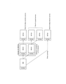
- FIG. 8 is a diagram showing an operation when the UE 100 according to the embodiment moves from the cell C1 to the cell C2.
- FIG. 8 shows an example in which cell C1 is managed by gNB200A and cell C2 is managed by gNB200B.
- the UE 100 performs handover or cell reselection when moving from cell C1 to cell C2.
- the handover means a cell switching operation of the UE 100 in the RRC connected state.
- the cell reselection is a cell switching operation of the UE 100 in the RRC idle state or the RRC inactive state.
- the UE 100 stores the MBS control information of the cell C1 in the cell C1 in association with the control area identifier (see step S3 in FIG. 7).
- the UE 100 receives the MBS system information transmitted on the broadcast control channel of the cell C2 when switching the cell from the cell C1 to the cell C2, and acquires the MBS control area setting in the MBS system information.
- the UE 100 uses the acquired control area identifier (cell C2) in the MBS control area setting. It is determined whether or not the control area identifier (control area identifier of cell C1) matches the control area identifier (control area identifier of cell C1) stored by itself. If they match, the UE 100 determines that the MBS control information (MBS control information in cell C1) stored by itself is valid, and does not receive (skip) the MBS control channel in cell C2. Then, the UE 100 attempts to receive the MBS traffic channel of the cell C2 based on the MBS control information (MBS control information of the cell C1) stored by itself, and receives the MBS data from the cell C2.
- the MBS control information MBS control information in cell C1 stored by itself
- the UE 100 reads the system information of the cell C2, and if the MBS control area range is the same, determines that the MBS control information of the cell C1 is valid in the cell C2, and receives the MBS control channel of the cell C2. Instead, it is possible to try to receive the MBS traffic channel in cell C2. This reduces the MBS reception interruption time.
- cell C1 and cell C2 are managed by separate gNB200
- cell C1 and cell C2 may be managed by the same gNB200.
- the UE 100 when the UE 100 moves from the cell C1 to the cell C2, the UE 100 acquires the control area identifier of the cell C2 before moving to the cell C2 while receiving the MBS from the cell C1. Can perform the action to be performed. Assuming that there is only one receiver for the UE 100, such an operation can be difficult. For example, the UE 100 needs to temporarily suspend the MBS reception from the cell C1 to acquire the control area identifier of the cell C2.
- the gNB 200 may transmit the adjacent cell information for specifying whether or not the cell C2 (adjacent cell) belongs to the same MBS control area range as the cell C1 to the UE 100.
- the UE 100 can grasp whether or not the cell C2 (adjacent cell) belongs to the same MBS control area range as the cell C1 based on the adjacent cell information from the cell C1. For example, the UE 100 determines whether or not MBS control information must be acquired from the adjacent cell at the time of cell switching after receiving and storing the adjacent cell information. For example, when cell C2 (adjacent cell) belongs to the same MBS control area range as cell C1, the UE 100 does not acquire (skip) the control area identifier of cell C2.
- the gNB 200 may transmit the adjacent cell information in the MBS system information via the broadcast control channel of the cell C1, or may transmit the adjacent cell information via the MBS control channel of the cell C1. ..
- the adjacent cell information includes the control area identifier of the adjacent cell (cell C2).
- the adjacent cell information may include a cell identifier and / or a frequency identifier and / or an MBS service identifier of the adjacent cell (cell C2), and a control area identifier associated with this identifier.
- the adjacent cell information may include an MBS control channel identifier and a control area identifier associated with this identifier.
- the adjacent cell information may be limited to the adjacent cell belonging to the same or different MBS control area range as the cell C1, and may include the cell identifier and / or the frequency identifier of the adjacent cell.
- the adjacent cell information may further include a system information area identifier indicating the system information area range of the adjacent cell.
- the UE 100 needs to receive the MBS control information from the cell C2.
- the gNB 200 (cell C1) transmits the MBS control information transmitted in the adjacent cell in the cell C1. do.
- the UE 100 in the cell C1 can acquire the MBS control information of the adjacent cell before moving to the adjacent cell. Therefore, when moving to the adjacent cell, MBS data can be promptly received from the adjacent cell based on the MBS control information acquired in advance.
- the gNB 200 may transmit the MBS control information of the adjacent cell via the broadcast control channel of the cell C1, or may transmit the MBS control information of the adjacent cell via the MBS control channel of the cell C1. good.
- the gNB 200 (cell C1) inputs the adjacent cell information about the adjacent cell as in the above embodiment. It may be transmitted at C1.
- FIG. 10 is a diagram showing the operation according to the modification example 1.
- FIG. 10 shows an example in which three cells are managed by separate gNB200s, but three cells may be managed by one gNB200.
- cell C1 and cell C2 belong to the same MBS control area range # 1, and cell C3 belongs to MBS control area range # 3.
- the gNB 200 (200A) that manages the cell C1 transmits the above-mentioned adjacent cell information in the cell C1 with respect to the cell C2.
- the UE 100 in the cell C1 grasps that the cell C2 belongs to the same MBS control area range # 1 as the cell C1 based on the adjacent cell information.
- the gNB 200 (200A) that manages the cell C1 transmits the MBS control information transmitted by the cell C3 on the MBS control channel in the cell C1.
- the gNB 200 (200A) may transmit at least a part of the above-mentioned adjacent cell information in the cell C1 in association with the MBS control information of the cell C3.
- the gNB 200 (200A) may further transmit the MBS system information transmitted by the cell C3 on the broadcast control channel in the cell C1.
- the UE 100 in the cell C1 receives and stores the MBS control information of the cell C3 from the cell C1.
- the UE 100 can quickly receive the MBS data from the cell C3 based on the stored MBS control information of the cell C3.
- the gNB 200 (200A) that manages the cell C1 may acquire MBS control information (MBS control channel setting) of the cell C3 from the gNB 200 (200C) that manages the cell C3 via the inter-base station interface.
- the gNB 200 (200A) may acquire MBS control information of cell C3 from the operator's device or core network.
- the gNB 200 (200A) transmits the acquired MBS control information of the cell C3 in the cell C1.
- the gNB 200 (200A) that manages the cell C1 may receive a change notification of the control area identifier of the cell C3 from the gNB 200 (200C) that manages the cell C3 via the inter-base station interface.
- the gNB 200 (200A) may receive a change notification of the control area identifier of the cell C3 from the operator's device or the core network.
- the gNB 200 (200A) grasps the change of the control area identifier of the cell C3 based on the received change notification.
- the gNB 200 may transmit the MBS control information of the cell C3 in the cell C1 in response to the request from the UE 100. Specifically, the UE 100 transmits a transmission request requesting MBS control information transmitted in the adjacent cell (cell C3) to the gNB 200. The gNB 200 transmits the MBS control information of the cell C3 to the UE 100 in response to the reception of this transmission request.
- the gNB 200 (200A) does not need to periodically transmit the MBS control information of the cell C3 in the cell C1, and if the MBS control information of the cell C3 is transmitted in the cell C1 when requested by the UE 100, the gNB 200 (200A) can transmit the MBS control information of the cell C3 in the cell C1. good. Therefore, the radio resource of the cell C1 can be saved.
- Random access preamble may be used as a transmission request.
- the UE 100 transmits a random access preamble using the PRACH resource selected by the UE 100 from a plurality of PRACH (Physical Random Access Channel) resources to the gNB 200 as a transmission request.
- PRACH Physical Random Access Channel
- Each of the plurality of PRACH resources is associated with at least one of an identifier of an adjacent cell, an MBS service identifier, and an identifier of an MBS control channel.
- FIG. 11 is a diagram showing another operation according to the modification example 1. In FIG. 11, the non-essential steps are shown by broken lines.
- the UE 100 may transmit a transmission request requesting transmission of MBS control information of an adjacent cell to the gNB 200.
- the UE 100 may request the gNB 200 to transmit the MBS system information of the adjacent cell in addition to the MBS control information of the adjacent cell.
- the transmission request may include MBS system information and / or the cell identifier and / or frequency identifier of the adjacent cell to be requested of the MBS control channel.
- the transmission request may include MBS system information and / or a control area identifier of the request target of the MBS control channel. If there are multiple MBS control channels in one adjacent cell, the transmit request may include the MBS control channel identifier of the requested MBS control channel.
- the UE 100 in the RRC idle state or the RRC connected state may transmit a random access preamble to the gNB 200 as a transmission request.
- the PRACH resource used for transmitting the random access preamble may be divided for each adjacent cell, for each MBS service identifier, or for each control area identifier. The information of such division is shared in advance by the UE 100 and the gNB 200, and the UE 100 selects the PRACH resource corresponding to the request target and uses it for the transmission of the random access preamble.
- the transmission request may request all MBS control information of the adjacent cell.
- the gNB 200 transmits the MBS control channel (and / or the MBS system information of the adjacent cell) of the adjacent cell based on the transmission request from the UE 100.
- This transmission may be a broadcast via the broadcast control channel or MBS control channel of cell C1, or may be a transmission by UE individual signaling (RRC message).
- Modification 2 is an embodiment mainly assuming a case where the UE 100 receives MBS from the cell C1 in the RRC idle state or the RRC inactive state.
- the UE 100 in the RRC idle state or the RRC inactive state transitions to the RRC connected state in the cell C1 when the MBS control area range to which the cell C1 belongs and the MBS control area range to which the adjacent cell belongs are different. Then, MBS control information of the adjacent cell is acquired from gNB200.
- FIG. 12 is a diagram showing an operation according to the second modification.
- step S21 the UE 100 performing MBS reception in the RRC idle state or the RRC inactive state requests a connection before reselecting the cell from the cell C1 to the adjacent cell (here, the cell C2). Send the message to cell C1.
- the transmission of the connection request message is triggered based on the radio status of cell C1 and / or cell C2.
- the threshold value to be compared with the wireless condition may be set in advance from the cell C1 to the UE 100.
- the connection request message may be an RRC Request message, which is a kind of RRC message.
- the connection request message may be an RRC Request Request message, which is a kind of RRC message.
- the gNB 200 that manages the cell C1 transmits a connection response message to the UE 100 in response to receiving the connection request message.
- the connection response message may be an RRC Setup message, which is a type of RRC message.
- the connection response message may be an RRC Resume message which is a kind of RRC message.
- the UE 100 transitioning to the RRC connected state transmits a notification message to the gNB 200.
- the UE 100 includes the MBS reception indicating that the UE 100 performs the MBS reception in the notification message.
- the UE 100 may include such MBS reception information in the connection request message in step S21.
- the MBS reception information may include the MBS service identifier of the MBS service received by the UE 100.
- the UE 100 may include measurement information indicating the measurement result for the adjacent cell (cell C2) in the notification message. Alternatively, the UE 100 may include such measurement information in the connection request message in step S21.
- the notification message may be an RRC Setup Complete message (in the case of the RRC idle state) or an RRC Reste Complete message (in the case of the RRC inactive state).
- the notification message may be an MBS interest indication message, which is a kind of RRC message.
- the notification message may be a measurement report (measurement report message) described later.
- step S24 when the UE 100 satisfies the handover criteria, the gNB 200 transmits a handover command message including the MBS control information of the adjacent cell (cell C2) to the UE 100.
- the handover command message is a kind of RRC message and is a message for instructing the UE 100 to perform a handover.
- the gNB200 (200A) that manages the cell C1 transmits a handover request to the gNB200 (200B) that manages the cell C2 prior to step S24. do.
- the handover request may include information that the UE 100 desires MBS reception.
- the gNB 200 (200B) that manages the cell C2 transmits a handover response including the MBS control information of the cell C2 to the gNB 200 (200A) that manages the cell C1 in response to the reception of the handover request.
- the gNB 200 (200A) that manages the cell C1 transmits a handover command message including the MBS control information in the handover response to the UE 100.
- the UE 100 executes the handover to the cell C2.
- the UE 100 may send a notification to the cell C2 that it wants to transition to the RRC idle state or the RRC inactive state.
- the UE 100 transitions from the RRC connected state to the RRC idle state or the RRC inactive state in the cell C2.
- the UE 100 receives MBS from the cell C1 in the RRC connected state. In this case, steps S21 and S22 in FIG. 12 are unnecessary.
- the UE 100 in the RRC connected state notifies the gNB 200 of the handover candidate cell belonging to the same MBS control area range as the cell C1 by the measurement report, so that the handover to this candidate cell can be executed. As a result, the UE 100 can promptly receive the MBS after the handover.
- the UE 100 in the RRC connected state transmits a measurement report to the gNB 200 based on whether or not the MBS control area range to which the cell C1 belongs and the MBS control area range to which the adjacent cell belongs are the same. Specifically, the UE 100 includes in the measurement report information on whether or not the MBS control area identifier is different (that is, the MBS control information needs to be reacquired) for each cell that reports the measurement result to the gNB 200 in the measurement report. ..
- the UE 100 in the RRC connected state measures each adjacent cell and confirms whether the control area identifier of the adjacent cell is the same as the control area identifier of the serving cell (cell C1).
- the MBS control area identifier of the adjacent cell may be provided to the UE 100 from the serving cell (cell C1), or may be acquired by the UE 100 reading the MBS system information of the adjacent cell.
- the UE 100 transmits a measurement report message to the gNB 200 (cell C1) when the measurement report is triggered.
- the cell identifier of the adjacent cell that includes the measurement result in the measurement report message includes information indicating that the control area identifier is the same as the cell C1 and / or the control area identifier. Information indicating that it is different from cell C1 is added. Such information may be information indicating an adjacent cell suitable for MBS reception (that is, a handover destination cell desired by itself).
- the UE 100 may include only the measurement information (cell identifier and measurement result) of the adjacent cell whose control area identifier is the same as that of the cell C1 in the measurement report message.
- the UE 100 may include only the cells whose control area identifier is the same as that of the cell C1 and whose measurement result satisfies the trigger condition of the measurement report in the measurement report message.
- the gNB 200 that manages the cell C1 determines the handover destination cell of the UE 100 based on the measurement report message from the UE 100. For example, the gNB 200 preferentially determines an adjacent cell having the same control area identifier as the cell C1 as the handover destination cell.
- the MBS control information includes a list of scheduling information for the MBS traffic channel.
- the MBS control information of each cell completely matches within the same MBS control area range.
- the MBS control information of each cell partially matches.
- the MBS control area range is set for each MBS traffic channel, with the scheduling information of the MBS traffic channel in the MBS control information as one unit.
- the control area identifier is set for each MBS control channel, whereas in the modification 3, the MBS traffic channel scheduling information (that is, MBS) in the MBS control channel (MBS control information) is set.
- MBS traffic channel scheduling information that is, MBS
- MBS control information is set.
- the scheduling information of the MBS traffic channel corresponding to this MBS service must be the same among the cells in this SFN.
- different MBS traffic channels have the same scheduling between cells.
- the gNB 200 transmits MBS control information including the scheduling information of the MBS traffic channel and the control area identifier associated with the MBS traffic channel via the MBS control channel. This makes it possible to finely set the MBS control area range subdivided for each MBS traffic channel as compared with the above-described embodiment.
- FIG. 13 is a diagram showing the operation according to the modification example 3. Here, the differences from the above-described embodiment will be mainly described.
- the gNB 200 that manages the cell C1 transmits MBS system information to the UE 100 via the broadcast control channel of the cell C1.
- the MBS system information includes scheduling information necessary for receiving the MBS control channel.
- MBS system information may include MBS control area settings as in the embodiments described above.
- the UE 100 grasps the scheduling of the MBS control channel based on the MBS system information received from the gNB 200 in step S1.
- the MBS system information includes the MBS service identifier of each MBS traffic channel in the cell C1 and the control area identifier associated with the MBS service identifier.
- the gNB 200 transmits MBS control information via the MBS control channel by scheduling according to the MBS system information transmitted in step S31.
- the MBS control information includes a list of scheduling information for the MBS traffic channel.
- the MBS traffic channel is provided for each MBS service (MBS service identifier).
- the MBS control information includes a control area identifier for each MBS traffic channel.
- the control area identifier may be associated with any one or more of the MBS service identifier, the group RNTI, and the MBS traffic channel scheduling information.
- the MBS control information may include information indicating the validity period of the control area identifier.
- the MBS control information may include information on adjacent cells (frequency identifier, cell identifier) corresponding to the same control area identifier.
- the control area identifier may be considered to be the SFN identification number.
- step S33 the UE 100 stores the MBS control information received from the gNB 200 in step S32.
- the UE 100 that receives the MBS data of a certain MBS service stores the scheduling information of the MBS traffic channel corresponding to the MBS service together with the control area identifier associated with the MBS traffic channel.
- the UE 100 grasps the scheduling of the MBS traffic channel corresponding to the MBS service of its own interest, and attempts to receive the MBS traffic channel.
- step S34 the gNB 200 transmits MBS data via the MBS traffic channel by scheduling according to the MBS control information transmitted in step S32.
- the UE 100 receives MBS data of the MBS traffic channel corresponding to the MBS service of its interest.
- the UE 100 that receives MBS in the RRC idle state or the RRC inactive state acquires the MBS system information of the cell C2 and confirms the MBS service identifier and its control area identifier included in the MBS system information.
- the control area identifier corresponding to the MBS service identifier of the MBS service that the UE 100 wants to receive matches the control area identifier of the MBS traffic channel (MBS service identifier) stored in advance, the MBS traffic channel is stored.
- MBS service identifier MBS traffic channel
- the gNB 200 that manages the cell C1 performs the handover control of the UE 100.
- the gNB200 (cell C1) is the MBS traffic channel scheduling information included in the MBS control information of the cell C2 for the UE 100 when the target cell (cell C2) is a different control area identifier for the MBS service identifier of interest to the UE 100.
- the handover command message includes the MBS traffic channel scheduling information included in the MBS control information of the cell C2.
- Modification 4 is an example for configuring SFN as described in modification 3.
- the gNB 200 transmits a message for synchronously transmitting the same MBS data among a plurality of gNB 200s to the adjacent gNB. That is, the SFN operates so that the gNB 200 is autonomously and decentralized.
- FIG. 14 is a diagram showing the operation according to the modified example 4.
- the network node 500 shown in FIG. 14 refers to a group of devices including a device of a core network and / or a device of an operator.
- the non-essential operation is shown by a broken line.
- the network node 500 sets the gNB 200A that manages the cell C1 as an anchor of a certain MBS service.
- the network node 500 may transmit (set) the identifier of each cell (each gNB) constituting the SFN of a certain MBS service to the gNB 200A. This identifier may be notified in association with the MBS service identifier.
- the gNB 200A may notify the network node 500 in advance of the presence or absence of the ability to act as an anchor.
- step S42 the gNB 200A transmits a message for requesting or setting the SFN configuration to the gNB 200B that manages the adjacent cell C2.
- the gNB 200B receives the message.
- the message may be sent and received via the inter-base station interface.
- the message may include the settings of the gNB200A itself, or may include the contents to be set by the gNB200B.
- the message contains at least one of the following information elements about SFN:
- ⁇ MBS service identifier It may further include an identifier as to whether or not it constitutes SFN.
- -Wireless resource settings Frequency resource information (eg, carrier frequency number applied to SFN, bandwidth portion (BWP), PRB information (start PRB, PRB width))
- Time resource information for example, system frame number applied to SFN, subframe number, period information (time applied to SFN (start time, end time, valid period))
- -MCS transport block size
- transport block size transport block size
- / or amount of data transmitted per subframe-System synchronization information for configuring SFN Mapping information between absolute time (GPS time, etc.) and system frame number (for example, correspondence information or offset value between a certain time and system frame number "0"), or system frame number offset value of gNB200A and gNB200B ⁇ SFN is configured.
- Data synchronization information for: Mapping information between absolute time (GPS time, etc.) and transmission data sequence number (for example, correspondence information or offset value between a certain time and transmission data sequence number "0"), or mapping information between the system frame number and transmission data sequence number. (For example, the transmission data sequence number corresponding to the system frame number "0", or the offset value). Alternatively, the amount of data to be transmitted per transmission opportunity (subframe, etc.). It should be noted that the above correspondence may be expressed by the opposite relations.
- the data synchronization information may be a system frame number corresponding to the transmission data sequence number “0”.
- Group RNTI Transport network settings-Bearer identifier-Endpoint identifier of gNB200A (IP address, GTP tunnel identifier) -Endpoint identifier of gNB200B (IP address, GTP tunnel identifier)
- step S43 gNB200B transmits a response message to the message in step S42 to gNB200A.
- the gNB 200A receives a response message.
- the response message may include the gNB200B setting (the above information element), or may simply be a notification of the completion of the setting.
- negotiation may be performed between both gNB200.
- the identifier space of the group RNTI may be divided into one that can be freely assigned by each gNB200 and one that is used in cooperation between gNB200 (only anchors can be numbered).
- the groups RNTI # 1 to 10 may be freely assigned, and the groups RNTI # 11 to 20 may be divided into those for cooperation.
- the currently assigned group RNTI may be periodically exchanged with the adjacent gNB200.
- step S44 the gNB 200A notifies the network node 500 that the settings of all the gNB 200Bs constituting the SFN have been completed.
- step S45 the network node 500 transmits the MBS data to the gNB 200A.
- the gNB 200A receives MBS data.
- step S46 the gNB 200A transfers the MBS data to the gNB 200B. In this way, the gNB 200A serves as a relay point (hub) of the user plane.
- each of gNB200A and gNB200B performs MBS transmission according to the above settings.
- change example 4 is based on SFN, but instead, MBS data may be transmitted synchronously in a cell with a different frequency.
- SFN is not configured, the same MBS data is simultaneously transmitted by a plurality of gNB200s having different frequencies.
- FIG. 14 shows an example in which MBS data is transmitted from gNB200B via gNB200A (steps S45 and S46), but the present invention is not limited to this.
- the gNB 200B may also receive MBS data directly from the network node 500.
- the endpoint identifier (IP address, GTP tunnel identifier) of the network node 500 may be notified in the message of step S42. Further, the endpoint identifier (IP address, GTP tunnel identifier) of the network node 500 may be notified in the response message in step S43.
- a program may be provided that causes a computer to execute each process performed by the UE 100 or gNB 200.
- the program may be recorded on a computer-readable medium.
- Computer-readable media can be used to install programs on a computer.
- the computer-readable medium on which the program is recorded may be a non-transient recording medium.
- the non-transient recording medium is not particularly limited, but may be, for example, a recording medium such as a CD-ROM or a DVD-ROM.
- a circuit that executes each process performed by the UE 100 or the gNB 200 may be integrated, and at least a part of the UE 100 or the gNB 200 may be configured as a semiconductor integrated circuit (chipset, SoC).
- UL feedback specifies the changes needed to improve the reliability of broadcast / multicast services.
- the level of reliability should be based on the requirements of the application / service provided.
- -PTM reception settings Receive point-to-multipoint transmissions by UEs in the RRC idle / RRC inactive state for the purpose of maintaining maximum commonality between the RRC connected state and the RRC idle / RRC inactive state. Specify the changes needed to make it possible.
- LTE eMBMS had several transmission schemes to enable multicast / broadcast services, such as MBSFN for Rel-9 and SC-PTM for Rel-13.
- MBSFN transmissions are designed primarily for multicell transmissions, and simultaneous transmissions are performed within the MBSFN area in MBSFN subframes (via PMCH).
- SC-PTM transmissions are focused on single cell transmissions and MBMSs are transmitted via PDSCH.
- FIG. 6 from the viewpoint of layer 2, MBSFN-related logical channels are mapped to MCH, while SC-PTM-related logical channels are mapped to DL-SCH.
- Findings 1 In LTE, MCCH and MTCH are mapped to MCH in the MBSFN transmission method, and SC-MCCH and SC-MTCH are mapped to DL-SCH in the SC-PTM transmission method.
- WID captures some limitations and assumptions, which help to consider what design is intended for this WI.
- the physical layer it is not expected that new numerology or physical channels will be introduced as shown below. This maps NR MBS related logical channels to DL-SCH.
- Physical layer Limits the scope of this WI to the current Rel-15 numerology, physical channels (PDCCH / PDSCH), and signals.
- Finding 2 The scope of this WI is limited to the existing numerology, physical channel (PDCCH / PDSCH). That is, it is assumed that NR MBS-related channels are mapped to DL-SCH.
- DL-SCH complies with the following restrictions and assumptions.
- Finding 3 DL-SCH (PDSCH) may be extended for multi-cell transmission in future releases.
- Proposal 1 RAN2 adopts the existing LTE SC-PTM specifications as the baseline for NR MBS design, including group scheduling mechanisms, service continuity support (such as adjacent cell information), and UE interest indications. Should be agreed.
- Proposal 2 If Proposal 1 is agreed, RAN2 will consider what will be extended in addition to the SC-PTM baseline to support the new / various use cases envisioned by NR MBS. Should be.
- LTE SC-PTM the configuration is provided by two messages: SIB20 and SC-MCCH.
- SIB 20 provides SC-MCCH scheduling information
- SC-MCCH provides SC-MTCH scheduling information including G-RNTI and TMGI, and adjacent cell information.
- the advantage of the LTE two-stage setting as shown in FIG. 15 is that the SC-MCCH scheduling is independent of the SIB20 scheduling in terms of repeat period, period, change period, and the like. In particular, frequent scheduling / updating of the SC-MCCH has been facilitated for delay-sensitive services and / or UEs that join late in the session. According to WID, one of the applications is group communication, so the same applies to NR MBS.
- Findings 4 In LTE, a two-step configuration using SIB20 and SC-MCCH is useful for different scheduling of these control channels. This is also useful for NR MBS.
- Proposal 3 RAN2 should agree on a two-step setting with different NR MBS messages, such as SC-PTM SIB20 and SC-MCCH.
- NR MBS is expected to support the various types of use cases described in WID.
- NR MBS is an application that is tolerant of delays such as IoT, from delay-sensitive applications such as mission-critical and V2X, in addition to other aspects of requirements from lossless applications such as software distribution to UDP-type streaming such as IPTV. It can be noticed that it should be properly designed for various requirements.
- control channels should be configured to meet the delay requirements from the delay-sensitive service. More signaling overhead can be incurred due to frequent scheduling.
- Purpose A of SA2 SI is about enabling general MBS services via 5GS, and the identified use cases that may benefit from this feature are public safety, mission critical, Includes, but is not limited to, V2X applications, transparent IPv4 / IPv6 multicast distribution, IPTV, software distribution over radio, group communications, and IoT applications.
- the setting channels may be separated. For example, one control channel frequently provides delay-sensitive services, and another control channel provides delay-tolerant services sparsely.
- LTE SC-PTM there is a limitation that one cell can have only one SC-MCCH. However, considering that more use cases are expected than LTE, NR MBS should remove such restrictions. If multiple SC-MCCHs are allowed in the cell, each SC-MCCH has different scheduling settings, such as repeat periods, that can be optimized for a particular service. Further consideration is needed on how to identify the SC-MCCH that the UE provides the service of interest.
- Proposal 4 RAN2 should discuss whether multiple control channels are supported in NR MBS cells, such as multiple SC-MCCHs that were not in LTE.
- NR MBS SC-MCCH ie on-demand SC-MCCH.
- SC-MCCH for delay-tolerant services is provided on demand, which can optimize signaling resource consumption.
- the network has another option to provide SC-MCCH on a regular basis, i.e., for delay-sensitive services rather than on-demand.
- Proposal 5 RAN2 should discuss options when control channels are provided on demand, such as on-demand SC-MCCH, which was not in LTE.
- the SIB provides SC-MTCH scheduling information directly, i.e., without SC-MCCH. This will provide optimizations for delay-tolerant services and / or power-sensitive UEs.
- the UE may request an SIB (on-demand), and the gNB may start providing the SIB and the corresponding service after the request from the plurality of UEs. These UEs do not need to monitor the repeatedly broadcast SC-MCCH.
- Proposal 6 RAN2 should discuss options such as SIB providing traffic channel configuration directly if multicast reception without SC-MCCH (ie, one-step configuration) is supported.
- LTE eMBMS In LTE eMBMS, there is no PDCP layer in the Uu protocol stack, as shown in FIG. 17, regardless of MBSFN or SC-PTM.
- one transmission per logical channel is allowed, i.e. only UM mode is used in the RLC layer and blind retransmission is not used in HARQ. In other words, the retransmission of lost packets relied on higher layer mechanisms in LTE eMBMS.
- Finding 6 In LTE eMBMS, the retransmission method is not supported in the AS layer.
- NR MBS seems to require a more reliable and flexible transmission method introduced as an AS function, as quoted from the following WID.
- NR MBS may require some enhancements as a function of the AS layer to improve the reliability and flexibility of multicast transmission / reception.
- HARQ MAC
- ARQ RLC
- PDCP status report
- Multicast / group cast HARQ feedback is not introduced in LTE.
- HARQ feedback of side link group cast that is, ACK / NACK or NACK-only, was supported. This is one of the possibilities of being reused and improving the performance of NR MBS.
- RAN2 may discuss the usefulness of HARQ feedback / retransmission to improve the reliability of multicast reception for idle, inactive, and connected UEs. There is.
- Proposal 7 RAN2 should discuss whether HARQ feedback / retransmission is useful for multicasting RRC idle, inactive, and connected UE NR MBS.
- Proposal 8 RAN2 should discuss whether RLC AM mode is supported for NR MBS multicast, at least for RRC connected UEs.
- FIG. 18 shows reliable receive and multicast / unicast switching enhancements.
- Support for the PDCP layer has the additional advantage that multicast bearers can be configured with split bearers and / or duplicated with unicast bearers. This has the potential of "dynamic changes in broadcast / multicast service delivery between multicast (PTM) and unicast (PTP) with default UE service continuity," as described in WID. It is also one of the mechanisms. Further studies are needed to determine whether various PDCP functions such as header compression and encryption can be supported by multicast reception.
- Proposal 9 RAN2 should discuss whether the PDCP layer is supported by a group cast of NR MBS at least in RRC connected UEs.
- the NR supports the SDAP layer to handle QoS flows within the radio bearer.
- the SDAP layer was not in eMBMS because it was not in conventional LTE.
- the SDAP layer can be assumed to be harmless to the reception of multicast data, but the need for the SDAP layer may actually depend on the assumptions / requirements of the higher layers. Therefore, RAN2 may have to wait for the progress of other WGs as to whether it is necessary.
- Finding 8 RAN2 may need to confirm with another WG whether the SDAP layer is necessary for NR MBS.
Landscapes
- Engineering & Computer Science (AREA)
- Computer Networks & Wireless Communication (AREA)
- Signal Processing (AREA)
- Multimedia (AREA)
- Computer Security & Cryptography (AREA)
- Mobile Radio Communication Systems (AREA)
Abstract
基地局からユーザ装置に対してマルチキャスト・ブロードキャストサービス(MBS)を提供する移動通信システムで用いる通信制御方法は、セルを管理する前記基地局が、前記セルのMBS制御チャネルを介して、MBSデータの受信に用いるMBS制御情報を前記ユーザ装置に送信することと、前記基地局が、前記MBS制御情報の少なくとも一部を適用可能なエリア範囲であるMBS制御エリア範囲を示す制御エリア識別子を前記ユーザ装置に送信することとを有する。
Description
本発明は、移動通信システムで用いる通信制御方法、基地局、及びユーザ装置に関する。
近年、第5世代(5G)の移動通信システムが注目されている。5Gシステムの無線アクセス技術(RAT:Radio Access Technology)であるNR(New Radio)は、第4世代の無線アクセス技術であるLTE(Long Term Evolution)に比べて、高速・大容量かつ高信頼・低遅延といった特徴を有する。
3GPP技術仕様書「3GPP TS 38.300 V16.2.0 (2020-07)」
第1の態様に係る通信制御方法は、基地局からユーザ装置に対してマルチキャスト・ブロードキャストサービス(MBS)を提供する移動通信システムで用いる通信制御方法であって、セルを管理する前記基地局が、前記セルのMBS制御チャネルを介して、MBSデータの受信に用いるMBS制御情報を前記ユーザ装置に送信することと、前記基地局が、前記MBS制御情報の少なくとも一部を適用可能なエリア範囲であるMBS制御エリア範囲を示す制御エリア識別子を前記ユーザ装置に送信することと、を有する。
第2の態様に係る基地局は、マルチキャスト・ブロードキャストサービス(MBS)を提供する移動通信システムで用いる基地局であって、前記基地局のセルのMBS制御チャネルを介して、MBSデータの受信に用いるMBS制御情報を前記ユーザ装置に送信する処理と、前記MBS制御情報の少なくとも一部を適用可能なエリア範囲であるMBS制御エリア範囲を示す制御エリア識別子を前記ユーザ装置に送信する処理と、を実行するプロセッサを有する。
第3の態様に係るユーザ装置は、マルチキャスト・ブロードキャストサービス(MBS)を提供する移動通信システムで用いるユーザ装置であって、セルのMBS制御チャネルを介して、MBSデータの受信に用いるMBS制御情報を受信する処理と、前記MBS制御情報の少なくとも一部を適用可能なエリア範囲であるMBS制御エリア範囲を示す制御エリア識別子を前記セルから受信する処理と、前記基地局からの前記MBS制御情報及び前記制御エリア識別子を記憶する処理と、前記記憶した制御エリア識別子が示す前記MBS制御エリア範囲内において、前記記憶したMBS制御情報に基づいて前記MBSデータを受信する処理と、を実行するプロセッサを有する。
5Gシステム(NR)にマルチキャスト・ブロードキャストサービスを導入することが検討されている。NRのマルチキャスト・ブロードキャストサービスは、LTEのマルチキャスト・ブロードキャストサービスよりも改善されたサービスを提供することが望まれる。
そこで、本開示は、改善されたマルチキャスト・ブロードキャストサービスを実現することを目的とする。
図面を参照しながら、実施形態に係る移動通信システムについて説明する。図面の記載において、同一又は類似の部分には同一又は類似の符号を付している。
(移動通信システムの構成)
まず、実施形態に係る移動通信システムの構成について説明する。図1は、実施形態に係る移動通信システムの構成を示す図である。この移動通信システムは、3GPP規格の第5世代システム(5GS:5th Generation System)に準拠する。以下において、5GSを例に挙げて説明するが、移動通信システムにはLTE(Long Term Evolution)システムが少なくとも部分的に適用されてもよい。
まず、実施形態に係る移動通信システムの構成について説明する。図1は、実施形態に係る移動通信システムの構成を示す図である。この移動通信システムは、3GPP規格の第5世代システム(5GS:5th Generation System)に準拠する。以下において、5GSを例に挙げて説明するが、移動通信システムにはLTE(Long Term Evolution)システムが少なくとも部分的に適用されてもよい。
図1に示すように、移動通信システムは、ユーザ装置(UE:User Equipment)100と、5Gの無線アクセスネットワーク(NG-RAN:Next Generation Radio Access Network)10と、5Gのコアネットワーク(5GC:5G Core Network)20とを有する。
UE100は、移動可能な無線通信装置である。UE100は、ユーザにより利用される装置であればどのような装置であっても構わないが、例えば、UE100は、携帯電話端末(スマートフォンを含む)やタブレット端末、ノートPC、通信モジュール(通信カード又はチップセットを含む)、センサ若しくはセンサに設けられる装置、車両若しくは車両に設けられる装置(Vehicle UE)、飛行体若しくは飛行体に設けられる装置(Aerial UE)である。
NG-RAN10は、基地局(5Gシステムにおいて「gNB」と呼ばれる)200を含む。gNB200は、基地局間インターフェイスであるXnインターフェイスを介して相互に接続される。gNB200は、1又は複数のセルを管理する。gNB200は、自セルとの接続を確立したUE100との無線通信を行う。gNB200は、無線リソース管理(RRM)機能、ユーザデータ(以下、単に「データ」という)のルーティング機能、モビリティ制御・スケジューリングのための測定制御機能等を有する。「セル」は、無線通信エリアの最小単位を示す用語として用いられる。「セル」は、UE100との無線通信を行う機能又はリソースを示す用語としても用いられる。1つのセルは1つのキャリア周波数に属する。
なお、gNBがLTEのコアネットワークであるEPC(Evolved Packet Core)に接続することもできる。LTEの基地局が5GCに接続することもできる。LTEの基地局とgNBとが基地局間インターフェイスを介して接続されることもできる。
5GC20は、AMF(Access and Mobility Management Function)及びUPF(User Plane Function)300を含む。AMFは、UE100に対する各種モビリティ制御等を行う。AMFは、NAS(Non-Access Stratum)シグナリングを用いてUE100と通信することにより、UE100のモビリティを管理する。UPFは、データの転送制御を行う。AMF及びUPFは、基地局-コアネットワーク間インターフェイスであるNGインターフェイスを介してgNB200と接続される。
図2は、実施形態に係るUE100(ユーザ装置)の構成を示す図である。
図2に示すように、UE100は、受信部110、送信部120、及び制御部130を備える。
受信部110は、制御部130の制御下で各種の受信を行う。受信部110は、アンテナ及び受信機を含む。受信機は、アンテナが受信する無線信号をベースバンド信号(受信信号)に変換して制御部130に出力する。
送信部120は、制御部130の制御下で各種の送信を行う。送信部120は、アンテナ及び送信機を含む。送信機は、制御部130が出力するベースバンド信号(送信信号)を無線信号に変換してアンテナから送信する。
制御部130は、UE100における各種の制御を行う。制御部130は、少なくとも1つのプロセッサ及び少なくとも1つのメモリを含む。メモリは、プロセッサにより実行されるプログラム、及びプロセッサによる処理に用いられる情報を記憶する。プロセッサは、ベースバンドプロセッサと、CPU(Central Processing Unit)とを含んでもよい。ベースバンドプロセッサは、ベースバンド信号の変調・復調及び符号化・復号等を行う。CPUは、メモリに記憶されるプログラムを実行して各種の処理を行う。
図3は、実施形態に係るgNB200(基地局)の構成を示す図である。
図3に示すように、gNB200は、送信部210、受信部220、制御部230、及びバックホール通信部240を備える。
送信部210は、制御部230の制御下で各種の送信を行う。送信部210は、アンテナ及び送信機を含む。送信機は、制御部230が出力するベースバンド信号(送信信号)を無線信号に変換してアンテナから送信する。
受信部220は、制御部230の制御下で各種の受信を行う。受信部220は、アンテナ及び受信機を含む。受信機は、アンテナが受信する無線信号をベースバンド信号(受信信号)に変換して制御部230に出力する。
制御部230は、gNB200における各種の制御を行う。制御部230は、少なくとも1つのプロセッサ及び少なくとも1つのメモリを含む。メモリは、プロセッサにより実行されるプログラム、及びプロセッサによる処理に用いられる情報を記憶する。プロセッサは、ベースバンドプロセッサと、CPUとを含んでもよい。ベースバンドプロセッサは、ベースバンド信号の変調・復調及び符号化・復号等を行う。CPUは、メモリに記憶されるプログラムを実行して各種の処理を行う。
バックホール通信部240は、基地局間インターフェイスを介して隣接基地局と接続される。バックホール通信部240は、基地局-コアネットワーク間インターフェイスを介してAMF/UPF300と接続される。なお、gNBは、CU(Central Unit)とDU(Distributed Unit)とで構成され(すなわち、機能分割され)、両ユニット間はF1インターフェイスで接続されてもよい。
図4は、データを取り扱うユーザプレーンの無線インターフェイスのプロトコルスタックの構成を示す図である。
図4に示すように、ユーザプレーンの無線インターフェイスプロトコルは、物理(PHY)レイヤと、MAC(Medium Access Control)レイヤと、RLC(Radio Link Control)レイヤと、PDCP(Packet Data Convergence Protocol)レイヤと、SDAP(Service Data Adaptation Protocol)レイヤとを有する。
PHYレイヤは、符号化・復号、変調・復調、アンテナマッピング・デマッピング、及びリソースマッピング・デマッピングを行う。UE100のPHYレイヤとgNB200のPHYレイヤとの間では、物理チャネルを介してデータ及び制御情報が伝送される。
MACレイヤは、データの優先制御、ハイブリッドARQ(HARQ)による再送処理、及びランダムアクセスプロシージャ等を行う。UE100のMACレイヤとgNB200のMACレイヤとの間では、トランスポートチャネルを介してデータ及び制御情報が伝送される。gNB200のMACレイヤはスケジューラを含む。スケジューラは、上下リンクのトランスポートフォーマット(トランスポートブロックサイズ、変調・符号化方式(MCS))及びUE100への割当リソースブロックを決定する。
RLCレイヤは、MACレイヤ及びPHYレイヤの機能を利用してデータを受信側のRLCレイヤに伝送する。UE100のRLCレイヤとgNB200のRLCレイヤとの間では、論理チャネルを介してデータ及び制御情報が伝送される。
PDCPレイヤは、ヘッダ圧縮・伸張、及び暗号化・復号化を行う。
SDAPレイヤは、コアネットワークがQoS制御を行う単位であるIPフローとAS(Access Stratum)がQoS制御を行う単位である無線ベアラとのマッピングを行う。なお、RANがEPCに接続される場合、SDAPが無くてもよい。
図5は、シグナリング(制御信号)を取り扱う制御プレーンの無線インターフェイスのプロトコルスタックの構成を示す図である。
図5に示すように、制御プレーンの無線インターフェイスのプロトコルスタックは、図4に示したSDAPレイヤに代えて、RRC(Radio Resource Control)レイヤ及びNAS(Non-Access Stratum)レイヤを有する。
UE100のRRCレイヤとgNB200のRRCレイヤとの間では、各種設定のためのRRCシグナリングが伝送される。RRCレイヤは、無線ベアラの確立、再確立及び解放に応じて、論理チャネル、トランスポートチャネル、及び物理チャネルを制御する。UE100のRRCとgNB200のRRCとの間に接続(RRC接続)がある場合、UE100はRRCコネクティッド状態にある。UE100のRRCとgNB200のRRCとの間に接続(RRC接続)がない場合、UE100はRRCアイドル状態にある。UE100のRRCとgNB200のRRCとの間の接続がサスペンドされている場合、UE100はRRCインアクティブ状態にある。
RRCレイヤの上位に位置するNASレイヤは、セッション管理及びモビリティ管理等を行う。UE100のNASレイヤとAMF300のNASレイヤとの間では、NASシグナリングが伝送される。
なお、UE100は、無線インターフェイスのプロトコル以外にアプリケーションレイヤ等を有する。
(MBS)
次に、実施形態に係るMBSについて説明する。MBSは、NG-RAN10からUE100に対してブロードキャスト又はマルチキャスト、すなわち、1対多(PTM:Point To Multipoint)でのデータ送信を行うサービスである。MBSは、MBMS(Multimedia Broadcast and Multicast Service)と呼ばれてもよい。なお、MBSのユースケース(サービス種別)としては、公安通信、ミッションクリティカル通信、V2X(Vehicle to Everything)通信、IPv4又はIPv6マルチキャスト配信、IPTV、グループ通信、及びソフトウェア配信等がある。
次に、実施形態に係るMBSについて説明する。MBSは、NG-RAN10からUE100に対してブロードキャスト又はマルチキャスト、すなわち、1対多(PTM:Point To Multipoint)でのデータ送信を行うサービスである。MBSは、MBMS(Multimedia Broadcast and Multicast Service)と呼ばれてもよい。なお、MBSのユースケース(サービス種別)としては、公安通信、ミッションクリティカル通信、V2X(Vehicle to Everything)通信、IPv4又はIPv6マルチキャスト配信、IPTV、グループ通信、及びソフトウェア配信等がある。
LTEにおけるMBSの送信方式には、MBSFN(Multicast Broadcast Single Frequency Network)送信及びSC-PTM(Single Cell Point To Multipoint)送信の2種類がある。図6は、実施形態に係る下りリンクの論理チャネル(Logical channel)とトランスポートチャネル(Transport channel)との対応関係を示す図である。
図6に示すように、MBSFN送信に用いる論理チャネルはMTCH(Multicast Traffic Channel)及びMCCH(Multicast Control Channel)であり、MBSFN送信に用いるトランスポートチャネルはMCH(Multicast Control Channel)である。MBSFN送信は、主にマルチセル送信用に設計されており、複数のセルからなるMBSFNエリアにおいて各セルが同じMBSFNサブフレームで同じ信号(同じデータ)の同期送信を行う。
SC-PTM送信に用いる論理チャネルはSC-MTCH(Single Cell Multicast Traffic Channel)及びSC-MCCH(Single Cell Multicast Control Channel)であり、SC-PTM送信に用いるトランスポートチャネルはDL-SCH(Downlink Shared Channel)である。SC-PTM送信は、主に単一セル送信用に設計されており、セル単位でブロードキャスト又はマルチキャストでのデータ送信を行う。SC-PTM送信に用いる物理チャネルはPDCCH(Physical Downlink Control Channel)及びPDSCH(Physical Downlink Control Channel)であり、動的なリソース割当が可能になっている。
以下において、SC-PTM伝送方式を用いてMBSが提供される一例について主として説明するが、MBSFN伝送方式を用いてMBSが提供されてもよい。また、MBSがマルチキャストにより提供される一例について主として説明する。このため、MBSをマルチキャストと読み替えてもよい。但し、MBSがブロードキャストにより提供されてもよい。
また、以下において、MBSデータとは、MBSにより送信されるデータをいう。MBS制御チャネルとは、MCCH又はSC-MCCHをいい、MBSトラフィックチャネルとは、MTCH又はSC-MTCHをいうものとする。
ネットワークは、MBSセッションごとに異なるMBSサービスを提供できる。MBSサービスは、TMGI(Temporary Mobile Group Identity)及びセッション識別子のうち少なくとも1つにより識別され、これらの識別子のうち少なくとも1つをMBSサービス識別子と呼ぶ。このようなMBSサービス識別子は、MBSセッション識別子又はマルチキャストグループ識別子と呼ばれてもよい。
(移動通信システムの動作)
次に、上述の移動通信システムの構成及びMBSを前提として、一実施形態に係る移動通信システムの動作について説明する。
次に、上述の移動通信システムの構成及びMBSを前提として、一実施形態に係る移動通信システムの動作について説明する。
MBS受信を行うUE100はセルを跨いで移動し得る。このようなUE100がMBS受信を継続するためには少なくともセル切替の際にMBS制御チャネル(MBS制御情報)を切替先のセルで受信する必要がある。このため、UE100の負荷及び消費電力が増えるとともに、切替先のセルから速やかにMBSデータを受信することが難しいという問題がある。
一実施形態において、MBS制御情報を複数のセルからなるエリア範囲(以下、「MBS制御エリア範囲」と呼ぶ)内で共通化可能な機能(以下、「制御エリア機能」と呼ぶ)を導入する。これにより、MBS制御エリア範囲内においてセルを跨いでもMBS制御情報を使いまわすことができるため、上述の問題を解決できる。
すなわち、一実施形態に係るgNB200は、自セルのMBS制御チャネルを介して、MBSデータの受信に用いるMBS制御情報をUE100に送信する。gNB200は、MBS制御情報の少なくとも一部を適用可能なエリア範囲であるMBS制御エリア範囲を示す制御エリア識別子をUE100に送信する。これにより、UE100は、現在のセルのMBS制御情報を使いまわすことが可能なMBS制御エリア範囲を把握できる。
UE100は、gNB200からのMBS制御情報及び制御エリア識別子を記憶する。そして、UE100は、記憶した制御エリア識別子が示すMBS制御エリア範囲内において、記憶したMBS制御情報に基づいてMBSデータを受信する。このように、記憶したエリア範囲内ではセルを跨いでもMBS制御情報を使いまわしてMBSデータを受信できるため、UE100の負荷及び消費電力を抑制できるとともに、切替先のセルから速やかにMBSデータを受信しやすくなる。
図7は、一実施形態に係る移動通信システムの動作を示す図である。
図7に示すように、ステップS1において、セルC1を管理するgNB200は、セルC1のブロードキャスト制御チャネル(BCCH:Broadcast Control Channel)を介して、MBSシステム情報をUE100に送信する。MBSシステム情報の送信は、所定のRNTI(Radio Network Temporary Identifier)を用いてブロードキャストで行われる。UE100は、MBSシステム情報を受信する。なお、システム情報は、SIB(System Information Block)と呼ばれることがある。
MBSシステム情報は、MBS制御チャネルの受信に必要なスケジューリング情報を含む。例えば、MBSシステム情報は、MBS制御チャネルの内容(MBS制御情報)が変更され得る周期を示す情報と、MBS制御チャネル送信の時間間隔を無線フレーム数で示す情報と、MBS制御チャネルがスケジュールされる無線フレームのオフセットを示す情報と、MBS制御チャネルがスケジュールされるサブフレームを示す情報とのうち少なくとも1つを含む。
一実施形態において、MBSシステム情報は、MBS制御エリア設定をさらに含む。MBS制御エリア設定は、セルC1が制御エリア機能を適用可能か否か示す情報要素(以下、「適用可否フラグ」と呼ぶ)を含む。セルC1が制御エリア機能を適用可能である場合、MBSシステム情報は、制御エリア識別子を含む。但し、MBSシステム情報が存在する場合、暗示的に制御エリア機能が適用可能であるとみなし、適用可否フラグが存在しなくてもよい。
MBS制御エリア設定は、このMBS制御エリア設定が有効である期間を示す有効期限情報(例えば、ある無線フレームまで有効、ある時刻まで有効、ある時間内は有効)を含んでもよい。なお、この有効期限が満了した後に、MBS制御エリア範囲を構成する隣接セルは自身のMBS制御情報を変更してもよい。このような変更は、オペレータの装置により実施されてもよく、コアネットワークが実施してもよく、gNB200間シグナリングで実施されてもよい。
なお、制御エリア機能は、セルC1を含む複数セルでSFN(Single Frequency Network)を構成する場合のみ有効にできるという制限があってもよい。SFNとは、同じ周波数で運用される複数のセルが同じ信号を同時に送信するネットワークをいう。UE100は、当該複数のセルからの信号(合成信号)を、いずれのセルから送信されたものかを識別することなく受信する。SFNを構成するためのMBS制御チャネルについて制御エリア機能が有効化されてもよい。
また、制御エリア識別子は、システム情報エリア範囲を示すシステム情報エリア識別子と共通化されていてもよい。システム情報エリア範囲とは、MBSシステム情報を使いまわすことが可能なエリア範囲をいう。制御エリア識別子をシステム情報エリア識別子と共通化する場合、MBSシステム情報は、MBS制御情報がMBSシステム情報のエリア範囲の設定に準じることを示す情報を含んでもよい。すなわち、この情報は、システム情報エリア識別子を制御エリア識別子として取り扱うことを示す情報である。
セルC1に複数のMBS制御チャネルが存在してもよい。例えば、MBSサービスごとに又はMBSサービスカテゴリごとにMBS制御チャネルが設けられる。この場合、MBSシステム情報は、MBS制御チャネルごとにMBS制御エリア設定を含んでもよい。MBSシステム情報は、MBSサービス識別子及び/又はMBS制御チャネル識別子と、この識別子と対応付けられたMBS制御エリア設定とを含んでもよい。MBS制御エリア設定に代えて、又はMBS制御エリア設定に加えて、MBS制御チャネルと対応付けられたネットワークスライス識別子がMBSシステム情報に含まれてもよい。
UE100は、ステップS1でgNB200から受信したMBSシステム情報に基づいて、MBS制御チャネルのスケジューリングを把握する。また、UE100は、このMBSシステム情報に含まれるMBS制御エリア設定を記憶する。
ステップS2において、gNB200は、ステップS1で送信したMBSシステム情報に従ったスケジューリングで、MBS制御チャネルを介してMBS制御情報を送信する。MBS制御情報の送信は、所定のRNTIを用いてブロードキャスト(又はマルチキャスト)で行われる。
MBS制御情報は、MBSトラフィックチャネルのスケジューリング情報のリストを含む。MBSトラフィックチャネルは、MBSサービスごとに設けられる。MBSトラフィックチャネルのスケジューリング情報は、例えば、当該MBSトラフィックチャネルに対応するMBSサービス識別子(例えば、TMGI)及びグループRNTIと、当該MBSトラフィックチャネルのスケジューリング情報(DRX(Discontinuous Reception)情報)とを含む。グループRNTIは、MBSサービス識別子と1対1でマッピングされる。
ステップS3において、UE100は、ステップS2でgNB200から受信したMBS制御情報を、ステップS1でgNB200から受信したMBS制御情報に含まれるMBS制御エリア設定(少なくとも、制御エリア識別子)と対応付けて記憶する。また、UE100は、ステップS2でgNB200から受信したMBS制御情報に基づいて、MBSトラフィックチャネルのスケジューリングを把握する。例えば、UE100は、自身の興味のあるMBSサービスに対応するMBSトラフィックチャネルのスケジューリングを把握し、このMBSトラフィックチャネルの受信を試みる。
ステップS4において、gNB200は、ステップS2で送信したMBS制御情報に従ったスケジューリングで、MBSトラフィックチャネルを介してMBSデータを送信する。MBSデータの送信は、グループRNTIを用いてマルチキャスト(又はブロードキャスト)で行われる。UE100は、自身の興味のあるMBSサービスに対応するMBSトラフィックチャネルのMBSデータを受信する。
次に、上述の動作の後においてUE100がセルC1から他セル(隣接セル)であるセルC2に移動する場合について説明する。図8は、一実施形態に係るUE100がセルC1からセルC2に移動する場合の動作を示す図である。図8において、セルC1がgNB200Aにより管理され、セルC2がgNB200Bにより管理される一例を示している。
図8に示すように、UE100は、セルC1からセルC2に移動する際にハンドオーバ又はセル再選択を行う。ハンドオーバとは、RRCコネクティッド状態にあるUE100のセル切替動作をいう。セル再選択とは、RRCアイドル状態又はRRCインアクティブ状態にあるUE100のセル切替動作をいう。
UE100は、セルC1において、セルC1のMBS制御情報を制御エリア識別子と対応付けて記憶している(図7のステップS3参照)。UE100は、セルC1からセルC2へのセル切替にあたり、セルC2のブロードキャスト制御チャネルで送信されるMBSシステム情報を受信し、このMBSシステム情報中のMBS制御エリア設定を取得する。
ここで、取得したMBS制御エリア設定中の適用可否フラグがオン(すなわち、セルC2が制御エリア機能を適用可能)である場合、UE100は、取得したMBS制御エリア設定中の制御エリア識別子(セルC2の制御エリア識別子)が、自身が記憶している制御エリア識別子(セルC1の制御エリア識別子)と一致するか否かを判定する。一致する場合、UE100は、自身が記憶しているMBS制御情報(セルC1のMBS制御情報)が有効であると判定し、セルC2のMBS制御チャネルの受信を行わない(スキップする)。そして、UE100は、自身が記憶しているMBS制御情報(セルC1のMBS制御情報)に基づいて、セルC2のMBSトラフィックチャネルの受信を試み、セルC2からMBSデータを受信する。
このように、UE100は、セルC2のシステム情報を読んでMBS制御エリア範囲が同一であれば、セルC1のMBS制御情報がセルC2で有効であると判定し、セルC2のMBS制御チャネル受信を行わず、セルC2のMBSトラフィックチャネルの受信を試みることができる。これにより、MBS受信中断時間が削減される。
なお、図8の例において、セルC1及びセルC2が別々のgNB200により管理される一例を説明したが、図9に示すように、セルC1及びセルC2が同じgNB200により管理されていてもよい。
図8及び図9に示すように、UE100がセルC1からセルC2へ移動する場合、UE100は、セルC1からのMBS受信を行いながら、セルC2に移動する前にセルC2の制御エリア識別子を取得する動作を実行し得る。UE100の受信機が1つである場合を想定すると、このような動作が困難になり得る。例えば、UE100は、セルC1からのMBS受信を一時的に中断してセルC2の制御エリア識別子を取得する必要がある。
このため、gNB200(セルC1)は、セルC2(隣接セル)がセルC1と同じMBS制御エリア範囲に属するか否かを特定するための隣接セル情報をUE100に送信してもよい。UE100は、セルC1からの隣接セル情報に基づいて、セルC2(隣接セル)がセルC1と同じMBS制御エリア範囲に属するか否かを把握できる。例えば、UE100は、隣接セル情報を受信及び記憶した後、セル切替の際に、隣接セルからMBS制御情報を取得しなければならないかの判定を行う。例えば、セルC2(隣接セル)がセルC1と同じMBS制御エリア範囲に属する場合、UE100は、セルC2の制御エリア識別子の取得を行わない(スキップする)。
gNB200(セルC1)は、セルC1のブロードキャスト制御チャネルを介してMBSシステム情報中で隣接セル情報を送信してもよいし、セルC1のMBS制御チャネルを介して隣接セル情報を送信してもよい。
隣接セル情報は、隣接セル(セルC2)の制御エリア識別子を含む。隣接セル情報は、隣接セル(セルC2)のセル識別子及び/又は周波数識別子及び/又はMBSサービス識別子と、この識別子と対応付けられた制御エリア識別子とを含んでもよい。セルC2に複数のMBS制御チャネルが存在する場合、隣接セル情報は、MBS制御チャネル識別子と、この識別子と対応付けられた制御エリア識別子とを含んでもよい。或いは、隣接セル情報は、セルC1と同じ又は異なるMBS制御エリア範囲に属する隣接セルに限定して、この隣接セルのセル識別子及び/又は周波数識別子を含んでもよい。隣接セル情報は、隣接セルのシステム情報エリア範囲を示すシステム情報エリア識別子をさらに含んでもよい。
(変更例1)
次に、変更例1について、上述の実施形態との相違点を主として説明する。
次に、変更例1について、上述の実施形態との相違点を主として説明する。
上述の実施形態において、UE100は、セルC2(隣接セル)がセルC1と同じMBS制御エリア範囲に属していない場合、UE100は、セルC2からMBS制御情報を受信する必要がある。
変更例1において、gNB200(セルC1)は、セルC1が属するMBS制御エリア範囲と隣接セルが属するMBS制御エリア範囲とが異なる場合、当該隣接セル内で送信されるMBS制御情報をセルC1において送信する。これにより、セルC1に居るUE100は、当該隣接セルに移動する前に、当該隣接セルのMBS制御情報を取得できる。このため、当該隣接セルに移動した際に、予め取得しているMBS制御情報に基づいて当該隣接セルからMBSデータを速やかに受信できる。
gNB200(セルC1)は、セルC1のブロードキャスト制御チャネルを介して隣接セルのMBS制御情報を送信してもよいし、セルC1のMBS制御チャネルを介して隣接セルのMBS制御情報を送信してもよい。
なお、gNB200(セルC1)は、セルC1が属するMBS制御エリア範囲と隣接セルが属するMBS制御エリア範囲とが同じである場合、上述の実施形態と同様に当該隣接セルについての隣接セル情報をセルC1において送信してもよい。
図10は、変更例1に係る動作を示す図である。図10において、3つのセルが別々のgNB200により管理される一例を示しているが、3つのセルが1つのgNB200により管理されていてもよい。
図10に示すように、セルC1及びセルC2は同じMBS制御エリア範囲#1に属し、セルC3はMBS制御エリア範囲#3に属している。
セルC1を管理するgNB200(200A)は、セルC2について、上述の隣接セル情報をセルC1において送信する。セルC1に居るUE100は、この隣接セル情報に基づいて、セルC2がセルC1と同じMBS制御エリア範囲#1に属することを把握する。
セルC1を管理するgNB200(200A)は、セルC3について、セルC3がMBS制御チャネルで送信するMBS制御情報をセルC1において送信する。gNB200(200A)は、セルC3のMBS制御情報と対応付けて、上述の隣接セル情報の少なくとも一部の情報をセルC1において送信してもよい。gNB200(200A)は、セルC3がブロードキャスト制御チャネルで送信するMBSシステム情報をセルC1においてさらに送信してもよい。
セルC1に居るUE100は、セルC3のMBS制御情報をセルC1から受信して記憶する。UE100は、セルC1からセルC3に移動した際に、記憶しているセルC3のMBS制御情報に基づいてセルC3からMBSデータを速やかに受信できる。
セルC1を管理するgNB200(200A)は、セルC3を管理するgNB200(200C)から、基地局間インターフェイスを介して、セルC3のMBS制御情報(MBS制御チャネル設定)を取得してもよい。或いは、gNB200(200A)は、オペレータの装置又はコアネットワークからセルC3のMBS制御情報を取得してもよい。gNB200(200A)は、取得したセルC3のMBS制御情報をセルC1において送信する。
セルC1を管理するgNB200(200A)は、セルC3を管理するgNB200(200C)から、基地局間インターフェイスを介して、セルC3の制御エリア識別子の変更通知を受信してもよい。或いは、gNB200(200A)は、オペレータの装置又はコアネットワークからセルC3の制御エリア識別子の変更通知を受信してもよい。gNB200(200A)は、受信した変更通知に基づいて、セルC3の制御エリア識別子の変更を把握する。
なお、gNB200(200A)は、UE100からの要求に応じて、セルC3のMBS制御情報をセルC1において送信してもよい。具体的には、UE100は、隣接セル(セルC3)内で送信されるMBS制御情報を要求する送信要求をgNB200に送信する。gNB200は、この送信要求の受信に応じて、セルC3のMBS制御情報をUE100に送信する。これにより、gNB200(200A)は、セルC3のMBS制御情報を常にセルC1において周期的に送信する必要が無くなり、UE100から要求があったときにセルC3のMBS制御情報をセルC1において送信すればよい。このため、セルC1の無線リソースを節約できる。
送信要求としてランダムアクセスプリアンブルを用いてもよい。例えば、UE100は、複数のPRACH(Physical Random Access CHannel)リソースの中からUE100が選択したPRACHリソースを用いたランダムアクセスプリアンブルを送信要求としてgNB200に送信する。複数のPRACHリソースのそれぞれは、隣接セルの識別子、MBSサービス識別子、及びMBS制御チャネルの識別子のうち少なくとも1つと対応付けられている。
図11は、変更例1に係る他の動作を示す図である。図11において、必須ではないステップを破線で示している。
図11に示すように、ステップS11において、UE100は、隣接セルのMBS制御情報の送信を要求する送信要求をgNB200に送信してもよい。UE100は、隣接セルのMBS制御情報に加えて、隣接セルのMBSシステム情報の送信をgNB200に要求してもよい。
送信要求は、MBSシステム情報及び/又はMBS制御チャネルの要求対象の隣接セルのセル識別子及び/又は周波数識別子を含んでもよい。送信要求は、MBSシステム情報及び/又はMBS制御チャネルの要求対象の制御エリア識別子を含んでもよい。1つの隣接セルに複数のMBS制御チャネルが存在する場合、送信要求は、要求するMBS制御チャネルのMBS制御チャネル識別子を含んでもよい。
RRCアイドル状態又はRRCコネクティッド状態にあるUE100は、送信要求としてランダムアクセスプリアンブルをgNB200に送信してもよい。ランダムアクセスプリアンブルの送信に用いるPRACHリソースは、隣接セルごとに区分けされていてもよいし、MBSサービス識別子ごとに区分けされていてもよいし、制御エリア識別子ごとに区分けされていてもよい。このような区分けの情報は予めUE100及びgNB200で共有されており、UE100は、要求対象に対応するPRACHリソースを選択してランダムアクセスプリアンブルの送信に用いる。或いは、送信要求は、隣接セルのすべてのMBS制御情報を要求するものであってもよい。
ステップS12において、gNB200は、UE100からの送信要求に基づき、隣接セルのMBS制御チャネル(及び/又は隣接セルのMBSシステム情報)を送信する。この送信は、セルC1のブロードキャスト制御チャネル又はMBS制御チャネルを介したブロードキャストであってもよいし、UE個別シグナリング(RRCメッセージ)による送信であってもよい。
(変更例2)
次に、変更例2について、上述の実施形態との相違点を主として説明する。
次に、変更例2について、上述の実施形態との相違点を主として説明する。
変更例2は、UE100がRRCアイドル状態又はRRCインアクティブ状態でセルC1からMBS受信を行う場合を主として想定した実施例である。変更例2において、RRCアイドル状態又はRRCインアクティブ状態にあるUE100は、セルC1が属するMBS制御エリア範囲と隣接セルが属するMBS制御エリア範囲とが異なる場合、セルC1においてRRCコネクティッド状態に遷移したうえでgNB200から当該隣接セルのMBS制御情報を取得する。
図12は、変更例2に係る動作を示す図である。
図12に示すように、ステップS21において、RRCアイドル状態又はRRCインアクティブ状態でMBS受信を行うUE100は、セルC1から隣接セル(こではセルC2とする)へのセル再選択前に、接続要求メッセージをセルC1に送信する。接続要求メッセージの送信は、セルC1及び/又はセルC2の無線状況に基づいてトリガされる。無線状況と比較する閾値は、予めセルC1からUE100に設定されていてもよい。なお、RRCアイドル状態の場合、接続要求メッセージは、RRCメッセージの一種であるRRC Requestメッセージであってもよい。RRCインアクティブ状態の場合、接続要求メッセージは、RRCメッセージの一種であるRRC Resume Requestメッセージであってもよい。
ステップS22において、セルC1を管理するgNB200は、接続要求メッセージの受信に応じて、接続応答メッセージをUE100に送信する。RRCアイドル状態の場合、接続応答メッセージは、RRCメッセージの一種であるRRC Setupメッセージであってもよい。RRCインアクティブ状態の場合、接続応答メッセージは、RRCメッセージの一種であるRRC Resumeメッセージであってもよい。
ステップS23において、RRCコネクティッド状態に遷移するUE100は、通知メッセージをgNB200に送信する。UE100は、UE100がMBS受信を行うことを示すMBS受信を通知メッセージに含める。或いは、UE100は、このようなMBS受信情報を、ステップS21の接続要求メッセージに含めてもよい。MBS受信情報は、UE100が受信するMBSサービスのMBSサービス識別子を含んでもよい。
UE100は、隣接セル(セルC2)に対する測定結果を示す測定情報を通知メッセージに含めてもよい。或いは、UE100は、このような測定情報を、ステップS21の接続要求メッセージに含めてもよい。
通知メッセージは、RRC Setup Completeメッセージ(RRCアイドル状態の場合)であってもよいし、RRC Resume Completeメッセージ(RRCインアクティブ状態の場合)であってもよい。通知メッセージは、RRCメッセージの一種であるMBS興味インディケーションメッセージであってもよい。通知メッセージは、後述の測定報告(測定報告メッセージ)であってもよい。
ステップS24において、gNB200は、UE100がハンドオーバ基準を満足した場合、隣接セル(セルC2)のMBS制御情報を含むハンドオーバ指令メッセージをUE100に送信する。ハンドオーバ指令メッセージは、RRCメッセージの一種であって、ハンドオーバをUE100に指示するためのメッセージである。
なお、セルC1及びセルC2が互いに異なるgNB200により管理されている場合、ステップS24に先立ち、セルC1を管理するgNB200(200A)は、セルC2を管理するgNB200(200B)に対してハンドオーバ要求を送信する。ハンドオーバ要求は、UE100がMBS受信を希望する旨の情報を含んでもよい。セルC2を管理するgNB200(200B)は、ハンドオーバ要求の受信に応じて、セルC2のMBS制御情報を含むハンドオーバ応答を、セルC1を管理するgNB200(200A)に送信する。セルC1を管理するgNB200(200A)は、このハンドオーバ応答中のMBS制御情報を含むハンドオーバ指令メッセージをUE100に送信する。
UE100は、gNB200からハンドオーバ指令メッセージを受信すると、セルC2へのハンドオーバを実行する。UE100は、ハンドオーバの完了後、セルC2に対して、RRCアイドル状態又はRRCインアクティブ状態へ遷移したい旨の通知を送信してもよい。その結果、UE100は、セルC2において、RRCコネクティッド状態からRRCアイドル状態又はRRCインアクティブ状態へ遷移する。
或いは、UE100がRRCコネクティッド状態でセルC1からMBS受信を行う場合を想定してもよい。この場合、図12におけるステップS21及びS22は不要である。
RRCコネクティッド状態にあるUE100が、セルC1と同じMBS制御エリア範囲に属するハンドオーバ候補セルを、測定報告によってgNB200に通知することにより、この候補セルへのハンドオーバを実行可能になる。その結果、UE100は、ハンドオーバ後に速やかにMBS受信を行うことができる。
すなわち、RRCコネクティッド状態にあるUE100は、セルC1が属するMBS制御エリア範囲と隣接セルが属するMBS制御エリア範囲とが同じであるか否かに基づいた測定報告をgNB200に送信する。具体的には、UE100は、測定報告で測定結果をgNB200に報告する各セルについて、MBS制御エリア識別子が異なる(すなわち、MBS制御情報の再取得が必要)か否かに関する情報を測定報告に含める。
第1に、RRCコネクティッド状態にあるUE100は、各隣接セルの測定を行うとともに、隣接セルの制御エリア識別子がサービングセル(セルC1)の制御エリア識別子と同一か否かを確認する。
ここで、隣接セルのMBS制御エリア識別子は、サービングセル(セルC1)からUE100に提供されていてもよいし、隣接セルのMBSシステム情報をUE100が読むことで取得してもよい。
第2に、UE100は、測定報告がトリガされた場合、測定報告メッセージをgNB200(セルC1)に送信する。
ここで、セルC1でMBS受信を行うUE100は、当該測定報告メッセージに測定結果を含める隣接セルのセル識別子に、制御エリア識別子がセルC1と同一であることを示す情報及び/又は制御エリア識別子がセルC1と異なることを示す情報を付与する。このような情報は、MBS受信に適した隣接セル(すなわち、自身の希望するハンドオーバ先セル)を示す情報であってもよい。
或いは、UE100は、制御エリア識別子がセルC1と同一である隣接セルの測定情報(セル識別子及び測定結果)のみを測定報告メッセージに含めてもよい。UE100は、制御エリア識別子がセルC1と同一である隣接セルであって、かつ測定結果が測定報告のトリガ条件を満足したセルのみを測定報告メッセージに含めてもよい。
セルC1を管理するgNB200は、UE100からの測定報告メッセージに基づいてUE100のハンドオーバ先セルを決定する。例えば、gNB200は、制御エリア識別子がセルC1と同一である隣接セルを優先的にハンドオーバ先セルとして決定する。
(変更例3)
次に、変更例3について、上述の実施形態との相違点を主として説明する。
次に、変更例3について、上述の実施形態との相違点を主として説明する。
上述のように、MBS制御情報は、MBSトラフィックチャネルのスケジューリング情報のリストを含む。上述の実施形態では、同一のMBS制御エリア範囲内において、各セルのMBS制御情報が完全一致していると仮定していた。変更例3では、各セルのMBS制御情報が部分的に一致している場合を想定する。具体的には、変更例3では、MBS制御情報中のMBSトラフィックチャネルのスケジューリング情報を1単位として、MBSトラフィックチャネルごとにMBS制御エリア範囲を設定する。
すなわち、上述の実施形態では、制御エリア識別子をMBS制御チャネルごとに設定していたのに対して、変更例3では、MBS制御チャネル(MBS制御情報)内のMBSトラフィックチャネルスケジューリング情報(すなわち、MBSサービス識別子)ごとに制御エリア識別子を設定する。
例えば、あるMBSサービスについて同一周波数でSFN(Single Frequency Network)を構成する場合、このMBSサービスに対応するMBSトラフィックチャネルのスケジューリング情報をこのSFN内のセル間で同一にしなければならない。同様に、別のMBSトラフィックチャネルについてもセル間で同一スケジューリングとなる。
変更例3に係るgNB200は、MBSトラフィックチャネルのスケジューリング情報と、このMBSトラフィックチャネルと対応付けられた制御エリア識別子とを含むMBS制御情報を、MBS制御チャネルを介して送信する。これにより、上述の実施形態に比べて、MBSトラフィックチャネルごとに細分化されたMBS制御エリア範囲をきめ細かに設定可能になる。
図13は、変更例3に係る動作を示す図である。ここでは、上述の実施形態との相違点を主として説明する。
図13に示すように、ステップS31において、セルC1を管理するgNB200は、セルC1のブロードキャスト制御チャネルを介して、MBSシステム情報をUE100に送信する。MBSシステム情報は、MBS制御チャネルの受信に必要なスケジューリング情報を含む。MBSシステム情報は、上述の実施形態と同様に、MBS制御エリア設定を含んでもよい。UE100は、ステップS1でgNB200から受信したMBSシステム情報に基づいて、MBS制御チャネルのスケジューリングを把握する。
変更例3において、MBSシステム情報は、セルC1の各MBSトラフィックチャネルのMBSサービス識別子と、このMBSサービス識別子と対応付けられた制御エリア識別子とを含む。
ステップS32において、gNB200は、ステップS31で送信したMBSシステム情報に従ったスケジューリングで、MBS制御チャネルを介してMBS制御情報を送信する。MBS制御情報は、MBSトラフィックチャネルのスケジューリング情報のリストを含む。MBSトラフィックチャネルは、MBSサービス(MBSサービス識別子)ごとに設けられる。
変更例3において、MBS制御情報は、MBSトラフィックチャネルごとに制御エリア識別子を含む。MBS制御情報において、制御エリア識別子は、MBSサービス識別子、グループRNTI、及びMBSトラフィックチャネルスケジューリング情報のいずれかひとつ以上と紐づいていてもよい。MBS制御情報は、制御エリア識別子の有効期間を示す情報を含んでもよい。MBS制御情報は、同一の制御エリア識別子に対応する隣接セルの情報(周波数識別子、セル識別子)を含んでもよい。制御エリア識別子は、SFNの識別番号であると考えられてもよい。
ステップS33において、UE100は、ステップS32でgNB200から受信したMBS制御情報を記憶する。具体的には、あるMBSサービスのMBSデータを受信するUE100は、このMBSサービスに対応するMBSトラフィックチャネルのスケジューリング情報を、このMBSトラフィックチャネルと対応付けられた制御エリア識別子と共に記憶する。UE100は、自身の興味のあるMBSサービスに対応するMBSトラフィックチャネルのスケジューリングを把握し、このMBSトラフィックチャネルの受信を試みる。
ステップS34において、gNB200は、ステップS32で送信したMBS制御情報に従ったスケジューリングで、MBSトラフィックチャネルを介してMBSデータを送信する。UE100は、自身の興味のあるMBSサービスに対応するMBSトラフィックチャネルのMBSデータを受信する。
次に、UE100がセルC1から隣接セル(セルC2)に移動する場合について説明する(図8及び図9参照)。
RRCアイドル状態又はRRCインアクティブ状態においてMBS受信を行うUE100は、セルC2のMBSシステム情報を取得し、このMBSシステム情報に含まれるMBSサービス識別子及びその制御エリア識別子を確認する。ここで、UE100が受信したいMBSサービスのMBSサービス識別子に対応する制御エリア識別子が、予め記憶しているMBSトラフィックチャネル(MBSサービス識別子)の制御エリア識別子と一致する場合、このMBSトラフィックチャネルの記憶済みのスケジューリング情報が有効であると判定する。この場合、セルC2からのMBS制御情報の受信をスキップし、セルC2から速やかにMBSデータを受信できる。
一方、UE100がRRCコネクティッド状態にある場合、セルC1を管理するgNB200は、UE100のハンドオーバ制御を行う。gNB200(セルC1)は、UE100が興味を持つMBSサービス識別子について、ターゲットセル(セルC2)が異なる制御エリア識別子である場合、UE100に対してセルC2のMBS制御情報に含まれるMBSトラフィックチャネルスケジューリング情報を送信する。具体的には、上述の変更例2と同様にして、ハンドオーバ指令メッセージに、セルC2のMBS制御情報に含まれるMBSトラフィックチャネルスケジューリング情報を含める。
(変更例4)
次に、変更例4について、上述の実施形態との相違点を主として説明する。変更例4は、変更例3で説明したようなSFNを構成するための実施例である。変更例4において、gNB200は、同じMBSデータを複数のgNB200間で同期伝送するためのメッセージを隣接gNBに送信する。すなわち、SFNをgNB200が自律分散的に構成するように動作する。
次に、変更例4について、上述の実施形態との相違点を主として説明する。変更例4は、変更例3で説明したようなSFNを構成するための実施例である。変更例4において、gNB200は、同じMBSデータを複数のgNB200間で同期伝送するためのメッセージを隣接gNBに送信する。すなわち、SFNをgNB200が自律分散的に構成するように動作する。
図14は、変更例4に係る動作を示す図である。図14に示すネットワークノード500とは、コアネットワークの装置及び/又はオペレータの装置からなる装置群をいう。なお、図14において、必須ではない動作を破線で示している。
図14に示すように、ステップS41において、ネットワークノード500は、セルC1を管理するgNB200Aを、あるMBSサービスのアンカーとして設定する。ここで、ネットワークノード500は、あるMBSサービスのSFNを構成する各セル(各gNB)の識別子をgNB200Aに送信(設定)してもよい。この識別子は、MBSサービス識別子と紐づいて通知されてもよい。なお、アンカーとなれる能力の有無について事前にgNB200Aからネットワークノード500に通知しておいてもよい。
ステップS42において、gNB200Aは、隣接セルであるセルC2を管理するgNB200Bに対して、SFN構成の要求又は設定を行うためのメッセージを送信する。gNB200Bは、メッセージを受信する。メッセージは、基地局間インターフェイスを介して送受信されてもよい。
メッセージは、gNB200A自身の設定を含んでもよいし、gNB200Bが設定すべき内容を含んでもよい。例えば、メッセージは、SFNに関する次の情報要素のうち少なくとも1つを含む。
・MBSサービス識別子:
SFNを構成するか否かの識別子をさらに含んでもよい。
・無線リソース設定:
周波数リソース情報(例えば、SFNに適用するキャリア周波数番号、帯域幅部分(BWP)、PRB情報(開始PRB、PRB幅))
時間リソース情報(例えば、SFNに適用するシステムフレーム番号、サブフレーム番号、期間情報(SFNを適用する時間(開始時間、時間終了、有効期間))
・MCS、トランスポートブロックサイズ、及び/又はサブフレームあたりの送信データ量
・SFNを構成するためのシステム同期情報:
絶対時刻(GPS時刻など)とシステムフレーム番号のマッピング情報(例えば、ある時刻とシステムフレーム番号“0”の対応情報もしくはオフセット値)、或いは、gNB200AとgNB200Bのシステムフレーム番号オフセット値
・SFNを構成するためのデータ同期情報:
絶対時刻(GPS時刻など)と送信データシーケンス番号のマッピング情報(例えば、ある時刻と送信データシーケンス番号“0”の対応情報もしくはオフセット値)、或いは、前記システムフレーム番号と送信データシーケンス番号のマッピング情報(例えば、システムフレーム番号“0”と対応する送信データシーケンス番号、もしくはオフセット値)。もしくは、送信機会(サブフレーム等)あたりの送信データ量。
なお、上記対応関係はそれぞれ逆の関係で表現されてもよい。例えば、上記データ同期情報は、送信データシーケンス番号“0”と対応するシステムフレーム番号であってもよい。
・グループRNTI
・トランスポートネットワーク設定
・ベアラ識別子
・gNB200Aのエンドポイント識別子(IPアドレス、GTPトンネル識別子)
・gNB200Bのエンドポイント識別子(IPアドレス、GTPトンネル識別子)
ステップS43において、gNB200Bは、gNB200Aに対して、ステップS42のメッセージに対する応答メッセージを送信する。gNB200Aは、応答メッセージを受信する。応答メッセージは、gNB200Bの設定(上記の情報要素)を含んでもよいし、単に設定完了の通知であってもよい。
ここで、設定内容についてgNB200A及びgNB200B間で齟齬が出た場合(例えば、要求されたグループRNTIが既に割当済であったような場合)、両gNB200間でネゴシエーションが行われてもよい。
グループRNTIの識別子空間は、各gNB200が自由に割り当てて良いものと、gNB200間の協調で用いられるもの(アンカーのみ採番可能)とに分割されていてもよい。例えば、グループRNTI#1~10は自由に割当可能、グループRNTI#11~20は協調用というように分割されてもよい。もしくは、現在割当中のグループRNTIを隣接gNB200間で定期的に情報交換してもよい。
ステップS44において、gNB200Aは、ネットワークノード500に対して、SFNを構成する全てのgNB200Bの設定が完了したことを通知する。
SFNが構成された後、ステップS45において、ネットワークノード500は、MBSデータをgNB200Aに送信する。gNB200Aは、MBSデータを受信する。ステップS46において、gNB200Aは、MBSデータをgNB200Bに転送する。このように、gNB200Aは、ユーザプレーンの中継点(ハブ)となる。
ステップS47及びステップS48において、gNB200A及びgNB200B(SFN内gNB200)のそれぞれは、上記設定に従ってMBS送信を行う。
なお、変更例4はSFNを前提にしていたが、そうではなく、別周波数のセルでMBSデータの同期送信を行ってもよい。この場合、SFNは構成しないが、同じMBSデータを別周波数の複数gNB200が同時伝送することになる。
図14において、MBSデータをgNB200A経由でgNB200Bから送信する例を示した(ステップS45、S46)が、これに限らない。gNB200Bはネットワークノード500からMBSデータを直接受信することもあり得る。この場合、ステップS42のメッセージにおいて、ネットワークノード500のエンドポイント識別子(IPアドレス、GTPトンネル識別子)が通知されてもよい。また、ステップS43の応答メッセージにおいて、ネットワークノード500のエンドポイント識別子(IPアドレス、GTPトンネル識別子)が通知されてもよい。
(その他の実施形態)
上述の各変更例は、別個独立に実施する場合に限らず、2以上の変更例を組み合わせて実施可能である。また、上述の各変更例は、上述の実施形態の動作を必ずしも前提としなくてもよい。
上述の各変更例は、別個独立に実施する場合に限らず、2以上の変更例を組み合わせて実施可能である。また、上述の各変更例は、上述の実施形態の動作を必ずしも前提としなくてもよい。
UE100又はgNB200が行う各処理をコンピュータに実行させるプログラムが提供されてもよい。プログラムは、コンピュータ読取り可能媒体に記録されていてもよい。コンピュータ読取り可能媒体を用いれば、コンピュータにプログラムをインストールすることが可能である。ここで、プログラムが記録されたコンピュータ読取り可能媒体は、非一過性の記録媒体であってもよい。非一過性の記録媒体は、特に限定されるものではないが、例えば、CD-ROMやDVD-ROM等の記録媒体であってもよい。
また、UE100又はgNB200が行う各処理を実行する回路を集積化し、UE100又はgNB200の少なくとも一部を半導体集積回路(チップセット、SoC)として構成してもよい。
以上、図面を参照して実施形態について詳しく説明したが、具体的な構成は上述のものに限られることはなく、要旨を逸脱しない範囲内において様々な設計変更等をすることが可能である。
本願は、米国仮出願第63/060257号(2020年8月3日出願)の優先権を主張し、その内容の全てが本願明細書に組み込まれている。
(付記)
(導入)
NRマルチキャスト及びブロードキャストサービス(MBS)に関する改訂されたワークアイテムが承認された。ワークアイテムの目的は次の通りである。
(導入)
NRマルチキャスト及びブロードキャストサービス(MBS)に関する改訂されたワークアイテムが承認された。ワークアイテムの目的は次の通りである。
-RRCコネクティッド状態のUEのブロードキャスト/マルチキャストのRAN基本機能を規定する。
―UEがブロードキャスト/マルチキャストサービスを受信できるようにするグループスケジューリングメカニズムを規定する。
―この目的には、ユニキャスト受信との同時操作を可能にするために必要な拡張機能を規定することが含まれる。
―既定のUEのサービス継続性を備えたマルチキャスト(PTM)とユニキャスト(PTP)との間のブロードキャスト/マルチキャストサービス配信の動的変更のサポートを規定する。
-サービス継続性を備えた基本的なモビリティのサポートを規定する。
-(MCEによってホストされる機能などの)必要な調整機能がgNB-CUにあると想定して、ブロードキャスト/マルチキャストにおけるSA2 SIの結果を考慮して、RANアーキテクチャ及びインターフェイスに必要な変更を規定する。
-例えば、ULフィードバックによって、ブロードキャスト/マルチキャストサービスの信頼性を向上させるために必要な変更を規定する。信頼性のレベルは、提供されるアプリケーション/サービスの要件に基づくべきである。
-1つのgNB-DU内のブロードキャスト/マルチキャスト送信エリアの動的制御のサポートを研究し、それを有効にするために必要なものがある場合はそれを規定する。
-RRCアイドル/RRCインアクティブ状態のUEのブロードキャスト/マルチキャストのRAN基本機能を規定する。
-PTM受信の設定についてRRCコネクティッド状態とRRCアイドル/RRCインアクティブ状態の間で共通性を最大限維持することを目的として、RRCアイドル/RRCインアクティブ状態のUEによるPoint to Multipoint送信の受信を可能にするために必要な変更を規定する。
-PTM受信の設定についてRRCコネクティッド状態とRRCアイドル/RRCインアクティブ状態の間で共通性を最大限維持することを目的として、RRCアイドル/RRCインアクティブ状態のUEによるPoint to Multipoint送信の受信を可能にするために必要な変更を規定する。
この付記では、NR MBSの最初の考慮事項について議論する。
(議論)
(一般的な設計上の考慮事項)
LTE eMBMSには、Rel-9のMBSFN及びRel-13のSC-PTMなどの、マルチキャスト/ブロードキャストサービスを可能にするための伝送方式がいくつかあった。MBSFN送信は、主にマルチセル送信用に設計され、同時送信は、(PMCHを介した)MBSFNサブフレームにおいてMBSFNエリア内で実行される。一方で、SC-PTM送信は単一セル送信に焦点を合わせられ、MBMSはPDSCHを介して送信される。図6に示すように、レイヤ2の観点からは、MBSFN関連の論理チャネルはMCHにマッピングされるが、SC-PTM関連の論理チャネルはDL-SCHにマッピングされる。
所見1:LTEでは、MCCH及びMTCHはMBSFN伝送方式におけるMCHにマッピングされ、SC-MCCH及びSC-MTCHはSC-PTM伝送方式におけるDL-SCHにマッピングされる。
WIDは、いくつかの制限及び仮定をキャプチャしており、これは、このWIでどのような設計が意図されているかを考慮するのに役立つ。物理レイヤの場合、以下に示すように新しいnumerologyや物理チャネルが導入されることは想定されていない。これは、NR MBS関連の論理チャネルがDL-SCHにマッピングされる。
物理レイヤ:このWIの範囲を、現在のRel-15のnumerology、物理チャネル(PDCCH/PDSCH)、及び信号に制限する。
物理レイヤ:このWIの範囲を、現在のRel-15のnumerology、物理チャネル(PDCCH/PDSCH)、及び信号に制限する。
所見2:このWIの範囲は、既存のnumerology、物理チャネル(PDCCH/PDSCH)内に制限される。即ち、NR MBS関連のチャネルはDL-SCHにマッピングされることが想定される。
MBSFNが使用されていない場合でも、マルチセル送信は、例えば、CoMP送信とユーザプレーンパケットの同時配信との組み合わせなどによって、将来のリリースでDL-SCHによってサポートされ得るであろう。従って、DL-SCHは、以下の制限及び仮定に準拠する。
リリース17でこのWIに対して行われた設計上の決定は、将来のリリースで以下の機能の導入を妨げるものではない。
-gNB-DUレベルを超える複数のセルでのSFNの標準化でのサポート
-gNB-DUレベルを超える複数のセルでのSFNの標準化でのサポート
所見3:DL-SCH(PDSCH)は、将来のリリースでマルチセル送信用に拡張される可能性がある。
上記の所見の観点から、LTEで熟慮し、伝送方式だけでなく、設定やサービス継続性などの他のメカニズムもカバーするSC-PTMの仕様は、NR MBSの設計検討の良いベースラインになる可能性がある。従って、このWIでは、RAN2は既存のSC-PTMの仕様を可能な限り再利用し、NR MBSの新しい/様々なユースケースをサポートするためにSC-PTMの上に何が拡張されるかを検討すべきである。
提案1:RAN2は、既存のLTE SC-PTMの仕様を、グループスケジューリングメカニズム、(隣接セル情報などの)サービス継続性サポート、及びUEの興味インディケーションなど、NR MBS設計のベースラインとして採用することに合意すべきである。
提案2:提案1が合意される場合、RAN2は、NR MBSで想定される新しい/様々なユースケースをサポートするために、SC-PTMのベースラインに加えて何が拡張されるかを検討すべきである。
次のセクションでは、SC-PTMの仕様を議論のベースラインとして使用する。即ち、提案1が合意されると仮定する。但し、MBSFNのようなメカニズムが導入された場合でも、議論は再利用できる。
(制御プレーンの機能拡張の概要)
LTE SC-PTMにおいて、設定は2つのメッセージ、即ち、SIB20及びSC-MCCHによって提供される。SIB20は、SC-MCCHスケジューリング情報を提供し、SC-MCCHは、G-RNTI及びTMGIを含むSC-MTCHスケジューリング情報、及び隣接セル情報を提供する。
LTE SC-PTMにおいて、設定は2つのメッセージ、即ち、SIB20及びSC-MCCHによって提供される。SIB20は、SC-MCCHスケジューリング情報を提供し、SC-MCCHは、G-RNTI及びTMGIを含むSC-MTCHスケジューリング情報、及び隣接セル情報を提供する。
図15に示すようなLTEの2段階設定の利点は、SC-MCCHスケジューリングが、繰り返し期間、期間、変更期間などの観点でSIB20スケジューリングから独立していることであった。特に、セッションに遅れて参加する、遅延にセンシティブなサービス及び/又はUEに対して、SC-MCCHの頻繁なスケジューリング/更新が容易にした。WIDによると、アプリケーションの1つがグループ通信などであるため、NR MBSでも同様である。
所見4:LTEでは、SIB20及びSC-MCCHを使用した2段階設定が、これらの制御チャネルの異なるスケジューリングに役立つ。これは、NR MBSにも役立つ。
提案3:RAN2は、SC-PTMのSIB20やSC-MCCHなど、NR MBSのメッセージが異なる2段階設定に合意すべきである。
提案3に加えて、NR MBSは、WIDに記載されている様々なタイプのユースケースをサポートすることが想定される。NR MBSは、ソフトウェア配信などのロスレスアプリケーションからIPTVなどのUDPタイプのストリーミングまでの要件の他の側面に加えて、ミッションクリティカルやV2Xなどの遅延にセンシティブなアプリケーションから、IoTなどの遅延に寛容なアプリケーションまで、様々な要件に合わせて適切に設計すべきであることは気づかれ得る。
従って、制御チャネルの設計では、柔軟性及びそのリソース効率を考慮すべきである。そうしないと、例えば、遅延に寛容なサービスと遅延にセンシティブなサービスとが1つの制御チャネルで一緒に設定されている場合に、遅延にセンシティブなサービスからの遅延要件を満たすために、制御チャネルを頻繁にスケジュールする必要があるため、より多くのシグナリングオーバーヘッドが発生する可能性がある。
SA2 SIの目的Aは、5GSを介した一般的なMBSサービスを可能にすることに関するものであり、この機能の恩恵を受ける可能性のある特定されたユースケースには、公共安全、ミッションクリティカル、V2Xアプリケーション、透過的なIPv4/IPv6マルチキャスト配信、IPTV、無線を介したソフトウェア配信、グループ通信、及びIoTアプリケーションが含まれる(但し、これらに限定されない)。
所見5:NR MBS制御チャネルは、様々なタイプのユースケースに対して柔軟でリソース効率が必要とされる。
これらのユースケースでは、設定チャネルが分離されている可能性がある。例えば、ある制御チャネルは遅延にセンシティブなサービスを頻繁に提供し、別の制御チャネルは遅延に寛容なサービスをまばらに提供する。LTE SC-PTMでは、1つのセルは1つのSC-MCCHしか有せないという制限があった。しかしながら、LTEよりも多くのユースケースが想定されることを考慮すると、NR MBSはそのような制限を取り除くべきである。セル内で複数のSC-MCCHが許可されている場合、各SC-MCCHには、特定のサービス用に最適化可能な、繰り返し期間などの異なるスケジューリング設定がある。UEが興味のあるサービスを提供するSC-MCCHをどのように識別するかは更なる検討が必要である。
提案4:RAN2は、LTEになかった複数のSC-MCCHのように、NR MBSのセルで複数の制御チャネルがサポートされるかどうかを議論すべきである。
さらに、NRの新しいパラダイムは、オンデマンドSI送信のサポートである。この概念は、NR MBSのSC-MCCH、即ち、オンデマンドSC-MCCHに再利用され得る。例えば、遅延に寛容なサービス用のSC-MCCHはオンデマンドで提供されるため、シグナリングのリソース消費を最適化可能である。言うまでもなく、ネットワークには、SC-MCCHを定期的に、即ち、オンデマンドではなく、遅延にセンシティブなサービスなどに提供するための別のオプションがある。
提案5:RAN2は、LTEになかったオンデマンドSC-MCCHのように、制御チャネルがオンデマンドベースで提供される場合のオプションについて議論すべきである。
別の可能性として、これらのメッセージをマージすること、即ち、1段階設定をさらに検討され得る。例えば、図16に示すように、SIBは、SC-MTCHスケジューリング情報を直接、即ち、SC-MCCHなしで、提供する。これは、遅延に寛容なサービス及び/又は電力にセンシティブなUEのための最適化を提供するであろう。例えば、UEは、SIB(オンデマンド)を要求してもよく、gNBは、複数のUEからの要求の後に、SIB及び対応するサービスの提供を開始してもよい。これらのUEは、繰り返しブロードキャストされるSC-MCCHを監視する必要がない。
提案6:RAN2は、SC-MCCHを使用しないマルチキャスト受信(即ち、1段階設定)がサポートされている場合、SIBがトラフィックチャネル設定を直接提供するなどのオプションについて議論すべきである。
(ユーザプレーン拡張の概要)
LTE eMBMSでは、MBSFN又はSC-PTMに関係なく、図17に示すように、UuプロトコルスタックにはPDCPレイヤがない。さらに、論理チャネルごとに1回の送信が許可される、即ち、RLCレイヤではUMモードのみが使用され、HARQではブラインド再送信は使用されない。言い換えると、失われたパケットの再送信は、LTE eMBMSでは上位レイヤメカニズムに依存していた。
LTE eMBMSでは、MBSFN又はSC-PTMに関係なく、図17に示すように、UuプロトコルスタックにはPDCPレイヤがない。さらに、論理チャネルごとに1回の送信が許可される、即ち、RLCレイヤではUMモードのみが使用され、HARQではブラインド再送信は使用されない。言い換えると、失われたパケットの再送信は、LTE eMBMSでは上位レイヤメカニズムに依存していた。
所見6:LTE eMBMSでは、ASレイヤで再送信方式はサポートされていない。
一方で、NR MBSは、以下のWIDから引用されているように、AS機能として導入される、より信頼性が高く柔軟な伝送方式を必要としているようである。
[・・・]
既定のUEのサービス継続性を備えたマルチキャスト(PTM)とユニキャスト(PTP)との間のブロードキャスト/マルチキャストサービス配信の動的変更のサポートを規定する。
サービス継続性を備えた基本的なモビリティのサポートを規定する。
[・・・]
例えば、ULフィードバックによって、ブロードキャスト/マルチキャストサービスの信頼性を向上させるために必要な変更を規定する。信頼性のレベルは、提供されるアプリケーション/サービスの要件に基づくべきである。
[・・・]
既定のUEのサービス継続性を備えたマルチキャスト(PTM)とユニキャスト(PTP)との間のブロードキャスト/マルチキャストサービス配信の動的変更のサポートを規定する。
サービス継続性を備えた基本的なモビリティのサポートを規定する。
[・・・]
例えば、ULフィードバックによって、ブロードキャスト/マルチキャストサービスの信頼性を向上させるために必要な変更を規定する。信頼性のレベルは、提供されるアプリケーション/サービスの要件に基づくべきである。
[・・・]
所見7:NR MBSでは、ASレイヤの機能として、マルチキャスト送受信の信頼性及び柔軟性を向上させるためのいくつかの機能拡張が必要になる可能性がある。
グループキャストの再送信に関して、MAC(HARQ)、RLC(ARQ)、及び/又はPDCP(ステータスレポート)で処理されると見なされ得る。これらのメカニズムは、Uuと同様に、特にUEモビリティ、即ち、無線品質の低下及び/又はトランスポートパスの切り替えによって失われたパケットの補償に役立ち得る。
マルチキャスト/グループキャストのHARQフィードバックはLTEでは導入されていない。一方で、Rel-16 NR V2Xでは、サイドリンクグループキャストのHARQフィードバック、即ち、ACK/NACK又はNACK-only、がサポートされた。これは、再利用され、NR MBSのパフォーマンスを向上させる可能性の1つである。詳細を決定するのは最終的にRAN1次第だが、RAN2は、アイドル、インアクティブ、及びコネクティッドのUEのマルチキャスト受信の信頼性を向上させるためのHARQフィードバック/再送信の有用性について議論する可能性がある。
提案7:RAN2は、HARQフィードバック/再送信が、RRC アイドル、インアクティブ、及びコネクティッドのUEのNR MBSのマルチキャストに役立つかを議論すべきである。
ユニキャストの場合、受信の信頼性を高めるために、ダブルフィードバックループがHARQ及びARQでサポートされる。NR MBSでのグループキャストの場合も同様に、少なくともコネクティッドのUEの信頼性を向上させるために、可能性の1つとして、ARQ、即ち、RLC AMモードを導入する方法について議論すべきである。しかしながら、通常、ペアのアップリンクチャネルはグループキャストに使用できないと想定され得る。従って、潜在的な課題の1つは、UEがフィードバック(STATUS PDU)をgNBに送信する方法である。
提案8:RAN2は、少なくともRRCコネクティッドのUEについて、NR MBSのマルチキャストでRLC AMモードがサポートされているかどうか議論すべきである。
さらに、例えば、ソフトウェア配信のユースケースのように、NR MBSがハンドオーバ中にロスレス配信を考慮する必要がある場合、PDCPは、現在のようにドロップされたパケットを回復するのに役立つ。図18は、信頼性の高い受信及びマルチキャスト/ユニキャストスイッチングの機能拡張を示す。PDCPレイヤのサポートには、マルチキャストベアラをスプリットベアラで設定する及び/又はユニキャストベアラでデュプリケーションすることが可能であるというもう1つの利点がある。これは、WIDに記載されているように、「既定のUEのサービス継続性を備えたマルチキャスト(PTM)とユニキャスト(PTP)との間のブロードキャスト/マルチキャストサービス配信の動的変更」の潜在的なメカニズムの1つでもある。ヘッダ圧縮、暗号化などの様々なPDCP機能をマルチキャスト受信でサポートできるかは更なる検討が必要である。
提案9:RAN2は、PDCPレイヤが、少なくともRRCコネクティッドのUEにおけるNR MBSのグループキャストでサポートされるか議論すべきである。
最後に、NR MBSプロトコルスタックでSDAPが必要かどうかを検討すべきである。NRは、SDAPレイヤをサポートして無線ベアラ内のQoSフローを処理する。一方で、SDAPレイヤは従来のLTEにはなかったため、eMBMSにはなかった。SDAPレイヤは、マルチキャストデータの受信に害はないと想定され得るが、SDAPレイヤの必要性は、実際には上位レイヤの仮定/要件に依存する可能性がある。そのため、RAN2は、必要かどうかについて、他のWGの進行を待つ必要がある可能性がある。
所見8:RAN2は、NR MBSでSDAPレイヤが必要かどうかを他のWGで確認する必要がある可能性がある。
Claims (13)
- 基地局からユーザ装置に対してマルチキャスト・ブロードキャストサービス(MBS)を提供する移動通信システムで用いる通信制御方法であって、
セルを管理する前記基地局が、前記セルのMBS制御チャネルを介して、MBSデータの受信に用いるMBS制御情報を前記ユーザ装置に送信することと、
前記基地局が、前記MBS制御情報の少なくとも一部を適用可能なエリア範囲であるMBS制御エリア範囲を示す制御エリア識別子を前記ユーザ装置に送信することと、を有する
通信制御方法。 - 前記ユーザ装置が、前記基地局からの前記MBS制御情報及び前記制御エリア識別子を記憶することと、
前記ユーザ装置が、前記記憶した制御エリア識別子が示す前記MBS制御エリア範囲内において、前記記憶したMBS制御情報に基づいて前記MBSデータを受信することと、をさらに有する
請求項1に記載の通信制御方法。 - 前記制御エリア識別子を送信することは、ブロードキャスト制御チャネルを介して、前記制御エリア識別子を含むMBSシステム情報を送信することを含む
請求項1又は2に記載の通信制御方法。 - 前記基地局が、前記セルと異なる隣接セルが前記MBS制御エリア範囲に属するか否かを特定するための隣接セル情報を前記ユーザ装置に送信することをさらに有する
請求項1乃至3のいずれか1項に記載の通信制御方法。 - 前記基地局が、前記セルが属する前記MBS制御エリア範囲と隣接セルが属する前記MBS制御エリア範囲とが異なる場合、前記隣接セル内で送信されるMBS制御情報を前記セルにおいて送信することをさらに有する
請求項1乃至4のいずれか1項に記載の通信制御方法。 - 前記ユーザ装置が、前記隣接セル内で送信されるMBS制御情報を要求する送信要求を前記基地局に送信することと、
前記基地局が、前記送信要求の受信に応じて、前記MBS制御情報を前記ユーザ装置に送信することと、をさらに有する
請求項1乃至5のいずれか1項に記載の通信制御方法。 - 前記送信要求を送信することは、複数のPRACH(Physical Random Access CHannel)リソースの中から前記ユーザ装置が選択したPRACHリソースを用いたランダムアクセスプリアンブルを前記送信要求として前記基地局に送信することを含み、
前記複数のPRACHリソースのそれぞれは、隣接セルの識別子、MBSサービス識別子、及びMBS制御チャネルの識別子のうち少なくとも1つと対応付けられている、
請求項6に記載の通信制御方法。 - RRC(Radio Resource Control)アイドル状態又はRRCインアクティブ状態にある前記ユーザ装置が、前記セルが属する前記MBS制御エリア範囲と隣接セルが属する前記MBS制御エリア範囲とが異なる場合、前記セルにおいてRRCコネクティッド状態に遷移したうえで前記基地局から前記隣接セルのMBS制御情報を取得することをさらに有する
請求項1乃至7のいずれか1項に記載の通信制御方法。 - RRC(Radio Resource Control)コネクティッド状態にある前記ユーザ装置が、前記セルが属する前記MBS制御エリア範囲と隣接セルが属する前記MBS制御エリア範囲とが同じであるか否かに基づいた測定報告を前記基地局に送信することをさらに有する
請求項1乃至7のいずれか1項に記載の通信制御方法。 - 前記MBS制御情報を送信することは、MBSトラフィックチャネルのスケジューリング情報と、前記MBSトラフィックチャネルと対応付けられた前記制御エリア識別子とを含む前記MBS制御情報を送信することを含む
請求項1乃至9のいずれか1項に記載の通信制御方法。 - 前記基地局が、同じMBSデータを基地局間で同期伝送するためのメッセージを隣接基地局に送信することをさらに有する
請求項1乃至10のいずれか1項に記載の通信制御方法。 - マルチキャスト・ブロードキャストサービス(MBS)を提供する移動通信システムで用いる基地局であって、
前記基地局のセルのMBS制御チャネルを介して、MBSデータの受信に用いるMBS制御情報をユーザ装置に送信する処理と、
前記MBS制御情報の少なくとも一部を適用可能なエリア範囲であるMBS制御エリア範囲を示す制御エリア識別子を前記ユーザ装置に送信する処理と、を実行するプロセッサを有する
基地局。 - マルチキャスト・ブロードキャストサービス(MBS)を提供する移動通信システムで用いるユーザ装置であって、
セルのMBS制御チャネルを介して、MBSデータの受信に用いるMBS制御情報を受信する処理と、
前記MBS制御情報の少なくとも一部を適用可能なエリア範囲であるMBS制御エリア範囲を示す制御エリア識別子を前記セルから受信する処理と、
前記セルからの前記MBS制御情報及び前記制御エリア識別子を記憶する処理と、
前記記憶した制御エリア識別子が示す前記MBS制御エリア範囲内において、前記記憶したMBS制御情報に基づいて前記MBSデータを受信する処理と、を実行するプロセッサを有する
ユーザ装置。
Priority Applications (2)
| Application Number | Priority Date | Filing Date | Title |
|---|---|---|---|
| JP2022541539A JP7475458B2 (ja) | 2020-08-03 | 2021-08-02 | 通信制御方法、基地局、及びユーザ装置 |
| US18/163,737 US20230179963A1 (en) | 2020-08-03 | 2023-02-02 | Communication control method, base station, and user equipment |
Applications Claiming Priority (2)
| Application Number | Priority Date | Filing Date | Title |
|---|---|---|---|
| US202063060257P | 2020-08-03 | 2020-08-03 | |
| US63/060,257 | 2020-08-03 |
Related Child Applications (1)
| Application Number | Title | Priority Date | Filing Date |
|---|---|---|---|
| US18/163,737 Continuation US20230179963A1 (en) | 2020-08-03 | 2023-02-02 | Communication control method, base station, and user equipment |
Publications (1)
| Publication Number | Publication Date |
|---|---|
| WO2022030452A1 true WO2022030452A1 (ja) | 2022-02-10 |
Family
ID=80118008
Family Applications (1)
| Application Number | Title | Priority Date | Filing Date |
|---|---|---|---|
| PCT/JP2021/028635 WO2022030452A1 (ja) | 2020-08-03 | 2021-08-02 | 通信制御方法、基地局、及びユーザ装置 |
Country Status (3)
| Country | Link |
|---|---|
| US (1) | US20230179963A1 (ja) |
| JP (1) | JP7475458B2 (ja) |
| WO (1) | WO2022030452A1 (ja) |
Cited By (2)
| Publication number | Priority date | Publication date | Assignee | Title |
|---|---|---|---|---|
| WO2023197170A1 (zh) * | 2022-04-12 | 2023-10-19 | 北京小米移动软件有限公司 | 传输同步方法及装置、存储介质 |
| WO2024066858A1 (zh) * | 2022-09-29 | 2024-04-04 | 华为技术有限公司 | 一种通信的方法和装置 |
Family Cites Families (7)
| Publication number | Priority date | Publication date | Assignee | Title |
|---|---|---|---|---|
| KR100938078B1 (ko) | 2006-07-07 | 2010-01-21 | 삼성전자주식회사 | 통신 시스템에서 서비스 제공 시스템 및 방법 |
| WO2008115006A1 (en) | 2007-03-19 | 2008-09-25 | Lg Electronics Inc. | Discontinuous reception operation for constant data rate service |
| CN101340618B (zh) | 2007-07-05 | 2012-06-20 | 中国移动通信集团公司 | 资源调度方法、基站控制器、终端及资源调度系统 |
| KR101265424B1 (ko) | 2008-10-31 | 2013-05-16 | 닛본 덴끼 가부시끼가이샤 | 이동 통신 시스템, 제어국, 기지국, 통신 방법 및 프로그램 |
| US8885578B2 (en) | 2009-08-28 | 2014-11-11 | Electronics And Telecommunications Research Institute | Method of transmitting multicast broadcast service |
| KR101910459B1 (ko) | 2012-10-08 | 2019-01-04 | 한국전자통신연구원 | 이동통신시스템에서 멀티캐스트 서비스 제공을 위한 방법 및 장치 |
| KR102106581B1 (ko) | 2016-04-20 | 2020-05-04 | 콘비다 와이어리스, 엘엘씨 | 시스템 정보 프로비저닝 및 경량 접속 시그널링 |
-
2021
- 2021-08-02 JP JP2022541539A patent/JP7475458B2/ja active Active
- 2021-08-02 WO PCT/JP2021/028635 patent/WO2022030452A1/ja active Application Filing
-
2023
- 2023-02-02 US US18/163,737 patent/US20230179963A1/en active Pending
Non-Patent Citations (2)
| Title |
|---|
| "LTE; Evolved Universal Terrestrial Radio Access (E-UTRA); Radio Resource Control (RRC); Protocol specification (3GPP TS 36.331 version 16.1.1 Release 16)", ETSI TECHNICAL SPECIFICATION, EUROPEAN TELECOMMUNICATIONS STANDARDS INSTITUTE (ETSI), 650, ROUTE DES LUCIOLES ; F-06921 SOPHIA-ANTIPOLIS ; FRANCE, vol. 3GPP RAN, no. V16.1.1, 31 July 2020 (2020-07-31), 650, route des Lucioles ; F-06921 Sophia-Antipolis ; France , pages 1 - 1083, XP014380113 * |
| ERICSSON: "MBMS SI – Solution on MBMS service continuity", 3GPP DRAFT; S6-161553 WAS S6-161339 MBMS SI - SERVICE CONTINUITY, 3RD GENERATION PARTNERSHIP PROJECT (3GPP), MOBILE COMPETENCE CENTRE ; 650, ROUTE DES LUCIOLES ; F-06921 SOPHIA-ANTIPOLIS CEDEX ; FRANCE, vol. SA WG6, no. Reno, Nevada, USA; 20161114 - 20161118, 23 November 2016 (2016-11-23), Mobile Competence Centre ; 650, route des Lucioles ; F-06921 Sophia-Antipolis Cedex ; France , XP051201381 * |
Cited By (2)
| Publication number | Priority date | Publication date | Assignee | Title |
|---|---|---|---|---|
| WO2023197170A1 (zh) * | 2022-04-12 | 2023-10-19 | 北京小米移动软件有限公司 | 传输同步方法及装置、存储介质 |
| WO2024066858A1 (zh) * | 2022-09-29 | 2024-04-04 | 华为技术有限公司 | 一种通信的方法和装置 |
Also Published As
| Publication number | Publication date |
|---|---|
| US20230179963A1 (en) | 2023-06-08 |
| JP7475458B2 (ja) | 2024-04-26 |
| JPWO2022030452A1 (ja) | 2022-02-10 |
Similar Documents
| Publication | Publication Date | Title |
|---|---|---|
| WO2022085757A1 (ja) | 通信制御方法 | |
| WO2022149489A1 (ja) | 通信制御方法及びユーザ装置 | |
| WO2022085717A1 (ja) | 通信制御方法 | |
| WO2022025013A1 (ja) | 通信制御方法 | |
| WO2022239690A1 (ja) | 通信制御方法及びユーザ装置 | |
| WO2022153991A1 (ja) | 通信制御方法 | |
| US20230179963A1 (en) | Communication control method, base station, and user equipment | |
| US20230362595A1 (en) | Communication control method and user equipment | |
| WO2022085644A1 (ja) | 通信制御方法 | |
| WO2022210545A1 (ja) | 通信制御方法及びユーザ装置 | |
| US20240237143A1 (en) | Communication method | |
| US20240179722A1 (en) | Communication method | |
| JP7506227B2 (ja) | 基地局、方法及びシステム | |
| JP7508634B2 (ja) | 通信制御方法、基地局、ユーザ装置及びプロセッサ | |
| WO2022030518A1 (ja) | 通信制御方法 | |
| US20240179798A1 (en) | Communication method | |
| WO2024034569A1 (ja) | 通信方法 | |
| US20240022447A1 (en) | Communication control method and user equipment | |
| WO2022085646A1 (ja) | 通信制御方法 | |
| WO2022239691A1 (ja) | 通信制御方法 | |
| WO2022234847A1 (ja) | 通信制御方法及びユーザ装置 |
Legal Events
| Date | Code | Title | Description |
|---|---|---|---|
| 121 | Ep: the epo has been informed by wipo that ep was designated in this application |
Ref document number: 21852355 Country of ref document: EP Kind code of ref document: A1 |
|
| ENP | Entry into the national phase |
Ref document number: 2022541539 Country of ref document: JP Kind code of ref document: A |
|
| NENP | Non-entry into the national phase |
Ref country code: DE |
|
| 122 | Ep: pct application non-entry in european phase |
Ref document number: 21852355 Country of ref document: EP Kind code of ref document: A1 |