WO2022153754A1 - 前照灯の制御装置、前照灯の制御方法、前照灯システム - Google Patents
前照灯の制御装置、前照灯の制御方法、前照灯システム Download PDFInfo
- Publication number
- WO2022153754A1 WO2022153754A1 PCT/JP2021/045762 JP2021045762W WO2022153754A1 WO 2022153754 A1 WO2022153754 A1 WO 2022153754A1 JP 2021045762 W JP2021045762 W JP 2021045762W WO 2022153754 A1 WO2022153754 A1 WO 2022153754A1
- Authority
- WO
- WIPO (PCT)
- Prior art keywords
- headlight
- vehicle
- rainfall
- irradiation
- control device
- Prior art date
- Legal status (The legal status is an assumption and is not a legal conclusion. Google has not performed a legal analysis and makes no representation as to the accuracy of the status listed.)
- Ceased
Links
Images






Classifications
-
- B—PERFORMING OPERATIONS; TRANSPORTING
- B60—VEHICLES IN GENERAL
- B60Q—ARRANGEMENT OF SIGNALLING OR LIGHTING DEVICES, THE MOUNTING OR SUPPORTING THEREOF OR CIRCUITS THEREFOR, FOR VEHICLES IN GENERAL
- B60Q1/00—Arrangement of optical signalling or lighting devices, the mounting or supporting thereof or circuits therefor
- B60Q1/02—Arrangement of optical signalling or lighting devices, the mounting or supporting thereof or circuits therefor the devices being primarily intended to illuminate the way ahead or to illuminate other areas of way or environments
- B60Q1/04—Arrangement of optical signalling or lighting devices, the mounting or supporting thereof or circuits therefor the devices being primarily intended to illuminate the way ahead or to illuminate other areas of way or environments the devices being headlights
- B60Q1/14—Arrangement of optical signalling or lighting devices, the mounting or supporting thereof or circuits therefor the devices being primarily intended to illuminate the way ahead or to illuminate other areas of way or environments the devices being headlights having dimming means
- B60Q1/1415—Dimming circuits
- B60Q1/1423—Automatic dimming circuits, i.e. switching between high beam and low beam due to change of ambient light or light level in road traffic
- B60Q1/143—Automatic dimming circuits, i.e. switching between high beam and low beam due to change of ambient light or light level in road traffic combined with another condition, e.g. using vehicle recognition from camera images or activation of wipers
-
- B—PERFORMING OPERATIONS; TRANSPORTING
- B60—VEHICLES IN GENERAL
- B60Q—ARRANGEMENT OF SIGNALLING OR LIGHTING DEVICES, THE MOUNTING OR SUPPORTING THEREOF OR CIRCUITS THEREFOR, FOR VEHICLES IN GENERAL
- B60Q1/00—Arrangement of optical signalling or lighting devices, the mounting or supporting thereof or circuits therefor
- B60Q1/0017—Devices integrating an element dedicated to another function
- B60Q1/0023—Devices integrating an element dedicated to another function the element being a sensor, e.g. distance sensor, camera
-
- B—PERFORMING OPERATIONS; TRANSPORTING
- B60—VEHICLES IN GENERAL
- B60Q—ARRANGEMENT OF SIGNALLING OR LIGHTING DEVICES, THE MOUNTING OR SUPPORTING THEREOF OR CIRCUITS THEREFOR, FOR VEHICLES IN GENERAL
- B60Q1/00—Arrangement of optical signalling or lighting devices, the mounting or supporting thereof or circuits therefor
- B60Q1/02—Arrangement of optical signalling or lighting devices, the mounting or supporting thereof or circuits therefor the devices being primarily intended to illuminate the way ahead or to illuminate other areas of way or environments
- B60Q1/04—Arrangement of optical signalling or lighting devices, the mounting or supporting thereof or circuits therefor the devices being primarily intended to illuminate the way ahead or to illuminate other areas of way or environments the devices being headlights
- B60Q1/06—Arrangement of optical signalling or lighting devices, the mounting or supporting thereof or circuits therefor the devices being primarily intended to illuminate the way ahead or to illuminate other areas of way or environments the devices being headlights adjustable, e.g. remotely-controlled from inside vehicle
- B60Q1/08—Arrangement of optical signalling or lighting devices, the mounting or supporting thereof or circuits therefor the devices being primarily intended to illuminate the way ahead or to illuminate other areas of way or environments the devices being headlights adjustable, e.g. remotely-controlled from inside vehicle automatically
- B60Q1/085—Arrangement of optical signalling or lighting devices, the mounting or supporting thereof or circuits therefor the devices being primarily intended to illuminate the way ahead or to illuminate other areas of way or environments the devices being headlights adjustable, e.g. remotely-controlled from inside vehicle automatically due to special conditions, e.g. adverse weather, type of road, badly illuminated road signs or potential dangers
-
- B—PERFORMING OPERATIONS; TRANSPORTING
- B60—VEHICLES IN GENERAL
- B60Q—ARRANGEMENT OF SIGNALLING OR LIGHTING DEVICES, THE MOUNTING OR SUPPORTING THEREOF OR CIRCUITS THEREFOR, FOR VEHICLES IN GENERAL
- B60Q2300/00—Indexing codes for automatically adjustable headlamps or automatically dimmable headlamps
- B60Q2300/30—Indexing codes relating to the vehicle environment
- B60Q2300/31—Atmospheric conditions
- B60Q2300/312—Adverse weather
-
- B—PERFORMING OPERATIONS; TRANSPORTING
- B60—VEHICLES IN GENERAL
- B60Q—ARRANGEMENT OF SIGNALLING OR LIGHTING DEVICES, THE MOUNTING OR SUPPORTING THEREOF OR CIRCUITS THEREFOR, FOR VEHICLES IN GENERAL
- B60Q2300/00—Indexing codes for automatically adjustable headlamps or automatically dimmable headlamps
- B60Q2300/40—Indexing codes relating to other road users or special conditions
- B60Q2300/45—Special conditions, e.g. pedestrians, road signs or potential dangers
Definitions
- This disclosure relates to a headlight control device, a headlight control method, and a headlight system.
- Patent Document 1 when a weather condition in which visibility is poor in front of the vehicle is detected, the road surface portion in front of the vehicle corresponding to the road shape estimated by the road estimation unit is dimmed.
- a vehicle lighting device that controls the headlights so as to illuminate the light is described.
- the vehicle lighting device is controlled so as not to irradiate to a high place when it rains or snows.
- One of the specific aspects of the present disclosure is to improve the visibility of pedestrians.
- the control device of one aspect according to the present disclosure is (a) a control device that can be connected to the first headlight and the second headlight that are arranged apart from each other in the vehicle width direction at the front portion of the vehicle. Therefore, (b) the rainfall detecting means installed on the vehicle and (c) the rainfall detecting means installed on the vehicle and connected to the rainfall detecting means, the amount of rainfall detected by the rainfall detecting means is
- a headlight control device including a controller that controls the irradiation light of the first headlight to be relatively darker than the irradiation light of the second headlight when the value is equal to or more than a predetermined value. Is.
- the lighting state of the first headlights and the second headlights arranged apart from each other in the vehicle width direction at the front portion of the vehicle is controlled by a controller.
- the controller when the amount of rainfall detected by the rainfall detecting means is equal to or greater than a predetermined value, the irradiation light of the first headlight is irradiated by the second headlight.
- the headlight system of one aspect according to the present disclosure is a first type that is arranged apart from the control device of the above [1] in the vehicle width direction at the front portion of the vehicle and is connected to the control device.
- a headlight system that includes a headlight and a second headlight.
- FIG. 1 is a diagram showing a configuration of a headlight system of one embodiment.
- FIG. 2 is a flowchart showing an operation procedure of one embodiment in the controller of the headlight system.
- FIG. 3A is a diagram schematically showing a state of high beam irradiation in step S12.
- FIG. 3B is a diagram schematically showing a state of high beam irradiation in step S14.
- FIG. 4 is a flowchart showing an operation procedure of another embodiment in the controller of the headlight system.
- FIG. 5A is a diagram schematically showing a state of adaptive driving beam irradiation in step S24. Further, FIG. 5B is a diagram schematically showing the state of adaptive driving beam irradiation of the comparative example.
- FIG. 5A is a diagram schematically showing a state of adaptive driving beam irradiation in step S24.
- FIG. 5B is a diagram schematically showing the state of adaptive driving beam irradiation of the comparative example.
- FIG. 6 is a flowchart showing an operation procedure of another embodiment in the controller of the headlight system.
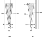
- 7 (A) and 7 (B) are diagrams schematically showing the state of adaptive driving beam irradiation in step S30.
- 8 (A) and 8 (B) are diagrams schematically showing the state of adaptive driving beam irradiation in the modified embodiment.
- FIG. 1 is a diagram showing a configuration of a headlight system of one embodiment.
- the illustrated headlight system includes a controller 1, an image pickup device 2, a lamp switch 3, a rainfall detecting means 4, and a pair of headlight units 5a and 5b.
- This headlight system is mounted on the front part of the vehicle to irradiate the front of the vehicle with light.
- a headlight control device includes a controller 1, an image pickup device 2, and a rainfall detecting means 4.
- the image pickup device 2 corresponds to a pedestrian detector
- the headlight unit 5a corresponds to the first headlight
- the headlight unit 5b corresponds to the second headlight.
- the controller 1 controls the light irradiation by the headlight units 5a and 5b.
- This controller 1 is configured by using, for example, a computer system equipped with a processor (CPU: Central Processing Unit), ROM (Read Only Memory), RAM (Random Access Memory), a storage device such as a flash memory, an input / output interface, and the like. be able to.
- the controller 1 of the present embodiment is in a state in which a predetermined function can be exhibited by reading and executing a program stored in a storage device (or ROM) in advance by a processor.
- the controller 1 includes an irradiation state setting unit 11 and a control signal generation unit 12 as functional blocks realized by program execution.
- the irradiation state setting unit 11 sets the headlight units 5a and 5b based on the situation in front of the own vehicle photographed by the imaging device 2, the operating state of the lamp switch 3, and the amount of rainfall detected by the rainfall detecting means 4. Set the state of the irradiation light by.
- the control signal generation unit 12 generates a control signal for forming the irradiation light corresponding to the irradiation light state set by the irradiation state setting unit 11 in the headlight units 5a and 5b, and generates the control signal for each headlight unit 5a and 5b. Supply to 5a and 5b.
- the image pickup device 2 detects a situation such as the position of a pedestrian based on an image obtained by photographing the space in front of the own vehicle, and includes a camera 21 and an image processing unit 22.
- the camera 21 captures the space in front of the own vehicle and generates image data.
- the image processing unit 22 performs image recognition processing on the image data generated by the camera 21 to perform image recognition processing in front of the own vehicle such as the position of a pedestrian, the position of a vehicle in front (preceding vehicle or oncoming vehicle), and a white line on the road. Detect the situation.
- the function of the image processing unit 22 may be provided in the controller 1. In that case, image data is supplied from the image pickup apparatus 2 to the controller 1, and the image recognition process is performed by executing a predetermined program in the controller 1.
- the lamp switch 3 is installed at a position that can be operated by the driver near the driver's seat of the own vehicle.
- the lamp switch 3 is operated by the driver when he / she wants the headlight units 5a and 5b to irradiate light.
- the rainfall detection means 4 detects the amount of rainfall in the place where the own vehicle exists, and outputs a signal (or data) indicating a change according to the amount of rainfall.
- the rainfall detecting means 4 various known ones can be used. As an example, it is possible to use a sensor installed inside the windshield of the own vehicle and detecting raindrops adhering to the outer surface of the glass by an optical method, as described in Japanese Patent Application Laid-Open No. 2006-29807. can. Further, as another example, the rainfall detecting means 4 may be configured to obtain information on the operating status from the wiper control device that controls the drive of the wiper of the vehicle based on the output of the sensor as described above. It is possible.
- the pair of headlight units 5a and 5b are mounted at predetermined positions on the left and right sides of the front part of the own vehicle, and operate in response to a control signal given from the controller 1 to form light emitted to the front of the own vehicle. ..
- the headlight units 5a and 5b of the present embodiment can form low beam (passing light) and high beam (running light) irradiation lights, and partially set a range according to the position of the vehicle in front. It is possible to form an adaptive driving beam (ADB) which is a dimmed (or extinguished) irradiation light.
- ADB adaptive driving beam
- a high beam or a low beam can be formed by a lamp unit having a structure in which a light source bulb is combined with a reflecting mirror and a shielding plate.
- light emitting elements such as LEDs (Light Emitting Diodes) are arranged in one direction or two directions, and an adaptive driving beam can be formed by using a lamp unit that can individually control the lighting state of each light emitting element. ..
- an adaptive driving beam can be formed by using a lamp unit provided with a light source, a liquid crystal element, and the like and capable of individually controlling the light transmission state of each pixel of the liquid crystal element.
- a lamp unit including a light emitting element such as a laser diode and a scanning element such as a mirror device that scans the light emitted from the light emitting element, and capable of controlling the on / off timing of the light emitting element and the scanning timing by the scanning element. It can also be used to form an adaptive driving beam. Further, in the lamp unit having these configurations, a high beam or a low beam may be formed in addition to the adaptive driving beam.
- FIG. 2 is a flowchart showing an operation procedure of one embodiment in the controller of the headlight system.
- a low beam is formed by each of the headlight units 5a and 5b according to the operation of the lamp switch 3 and is irradiated to the front of the own vehicle, and the amount of rainfall detected by the rainfall detecting means 4 is set.
- the operation of setting the irradiation mode of the high beam variably according to the situation will be described.
- the operation procedure shown in the flowchart shown here is an example, and the processing order of each step may be changed as long as the operation is not inconsistent, or other processing (not shown) may be added. The same applies to the flowcharts shown in FIGS. 4 and 6 described later.
- the irradiation state setting unit 11 of the controller 1 receives a signal indicating the operation state from the lamp switch 3, and when the switch instructing the operation of the high beam based on the signal is turned on (step S11; YES). , The irradiation state is set so that the high beam is lit by the left and right headlight units 5a and 5b, respectively (step S12).
- a control signal is generated by the control signal generation unit 12 and output to the headlight units 5a and 5b, and the high beam formed by the headlight units 5a and 5b is self-propelled. It is illuminated in front of the vehicle.
- the irradiation state setting unit 11 is centered in the vehicle width direction of the vehicle.
- the high beam (right high beam) by the headlight unit 5a located on the same side as the driver's seat is dimmed so as to be relatively dark, and the high beam (left side) by the headlight unit 5b on the opposite side of the driver's seat is dimmed.
- the irradiation state is set so that the brightness of the high beam) is maintained (step S14).
- step S13 When the irradiation state is set, a control signal is generated by the control signal generation unit 12 and output to the headlight units 5a and 5b, and the high beam formed by the headlight units 5a and 5b is self-propelled. It is illuminated in front of the vehicle. On the other hand, if the amount of rainfall is not equal to or higher than the predetermined value (step S13; NO), the process returns to step S11.
- the predetermined value of rainfall may be arbitrarily set based on an experiment or the like, and may be set to, for example, 20 mm / hour. Further, regarding the "dimming" of the right high beam, it is sufficient if it is relatively darker than the left high beam.
- the luminous intensity may be 1/10 or less, or the luminous intensity may be substantially 0. It may be. It is preferable that the luminous intensity is at least 1/2 that of the left high beam.
- step S15 when the irradiation state setting unit 11 receives a signal indicating the operation state from the lamp switch 3 and the switch instructing the operation of the high beam is turned off based on the signal (step S15; YES), The irradiation state is set so that the high beams from the left and right headlight units 5a and 5b are turned off (step S16).
- step S16 When the irradiation state is set, a control signal is generated by the control signal generation unit 12 and output to the headlight units 5a and 5b, and the high beam by the headlight units 5a and 5b is turned off. Then, the process returns to step S11.
- step S11 NO
- step S11 NO
- step S17 the process returns to step S11.
- step S15 when the switch for instructing the operation of the high beam is not turned off in step S15 (step S15; NO), the irradiation state setting unit 11 determines the amount of rainfall based on the signal output by the amount of rainfall detecting means 4. If it is smaller than the value (step S18; YES), the process returns to step S11. In this case, if the switch instructing the operation of the high beam is on, the left and right high beams are lit (step S12), and if the rainfall is still smaller than the predetermined value (step S13; NO), the lit state of each high beam is maintained. To.
- step 18 If the amount of rainfall is not smaller than the predetermined value, that is, if it is equal to or greater than the predetermined value (step 18; NO), the process returns to step S15. In this case, if the switch instructing the operation of the high beam is on, the high beam 105a is maintained in a dimmed state while the amount of rainfall is equal to or higher than a predetermined value (step S14).
- FIG. 3A is a diagram schematically showing the state of high beam irradiation in step S12.
- left-hand traffic is legal and the driver's seat is installed on the right side of the vehicle.
- FIG. 3A and FIG. 3B described later the state of the own vehicle 100 traveling in the left lane of the two-lane road is shown in a plan view from above.
- reference numeral d schematically indicates the position of the driver's seat.
- the high beams 105a and 105b formed by the headlight units 5a and 5b are irradiated to the front of the own vehicle 100 while partially overlapping.
- FIG. 3B is a diagram schematically showing the state of high beam irradiation in step S14.
- the high beam 105a formed by the headlight unit 5a on the same side as the position d of the driver's seat is dimmed to a state substantially close to the state of being turned off (may be completely turned off).
- the high beam 105b formed by the headlight unit 5b on the opposite side is maintained to be lit with sufficient luminous intensity.
- FIG. 4 is a flowchart showing an operation procedure of another embodiment in the controller of the headlight system.
- a low beam is formed by each of the headlight units 5a and 5b according to the operation of the lamp switch 3 and is irradiated to the front of the own vehicle, and the amount of rainfall detected by the rainfall detecting means 4 is set.
- An operation of variably setting the irradiation mode of the adaptive driving beam (ADB) will be described accordingly.
- the irradiation state setting unit 11 When the irradiation state setting unit 11 receives a signal indicating the operation state from the lamp switch 3 and the switch instructing the operation of the adaptive driving beam is turned on based on the signal (step S21; YES), The irradiation state is set so that the adaptive driving beams by the left and right headlight units 5a and 5b are lit (step S22). In this case, the irradiation state setting unit 11 irradiates so as to form an adaptive driving beam which is irradiation light in which the range corresponding to the position of the vehicle in front detected by the image pickup device 2 is partially dimmed (or turned off). Set the state.
- a control signal is generated by the control signal generation unit 12 and output to the headlight units 5a and 5b, and the adaptive driving beam formed by the headlight units 5a and 5b is formed. Is irradiated in front of the own vehicle.
- the irradiation state setting unit 11 is in front of the same side as the driver's seat.
- the adaptive driving beam (ADB on the right side) by the headlight unit 5a is dimmed so as to be relatively dark, and the adaptive driving beam (ADB on the left side) by the headlight unit 5b on the opposite side has a narrower irradiation range and is relative.
- the irradiation state is set so that the irradiation is biased toward the shoulder side of the road far from the own vehicle (step S24).
- step S23 When the irradiation state is set, a control signal is generated by the control signal generation unit 12 and output to the headlight units 5a and 5b, and the adaptive driving beam formed by the headlight units 5a and 5b is formed. Is irradiated in front of the own vehicle. On the other hand, if the amount of rainfall is not equal to or higher than the predetermined value (step S23; NO), the process returns to step S21.
- FIG. 5A is a diagram schematically showing the state of adaptive driving beam irradiation in step S24.
- FIG. 5B is a diagram schematically showing the state of adaptive driving beam irradiation of the comparative example.
- the adaptive driving beam 105a formed by the headlight unit 5a on the same side as the position d of the driver's seat is dimmed to a state substantially close to the state of being turned off (may be completely turned off). ).
- the adaptive driving beam 105c formed by the headlight unit 5b on the opposite side has a narrower irradiation range than the adaptive driving beam 105b, and is unevenly irradiated to the side of the road opposite to the driver's seat. It is formed so as to.
- the irradiation state setting unit 11 receives a signal indicating the operation state from the lamp switch 3, and when the switch instructing the operation of the adaptive driving beam is turned off based on the signal (step S25; YES). ), The irradiation state is set so that the high beams from the left and right headlight units 5a and 5b are turned off (step S26).
- a control signal is generated by the control signal generation unit 12 and output to the headlight units 5a and 5b, and the adaptive driving beam by the headlight units 5a and 5b is turned off. To. After that, the process returns to step S21.
- step S21 even when the switch instructing the operation of the adaptive driving beam is off instead of on in step S21 (step S21; NO), the irradiation state is set by the irradiation state setting unit 11, and each headlight unit is set.
- the adaptive driving beam according to 5a and 5b is turned off (step S27). After that, the process returns to step S21.
- step S25; NO when the switch instructing the operation of the adaptive driving beam is not turned off (step S25; NO), the irradiation state setting unit 11 sets the rainfall amount to a predetermined value based on the signal output by the rainfall detecting means 4. If it is smaller than (step S28; YES), the process returns to step S21. In this case, if the switch instructing the operation of the adaptive driving beam is on, the left and right adaptive driving beams are turned on (step S22), and if the rainfall is still smaller than the predetermined value (step S23; NO), each adaptive driving beam is turned on. The lighting state of is maintained.
- step 28; NO If the amount of rainfall is not smaller than the predetermined value, that is, if it is equal to or greater than the predetermined value (step 28; NO), the process returns to step S25. In this case, if the switch instructing the operation of the adaptive driving beam is on, the adaptive driving beam 105a is maintained in a dimmed state while the amount of rainfall is equal to or higher than a predetermined value (step S24).
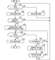
- FIG. 6 is a flowchart showing an operation procedure of another embodiment in the controller of the headlight system. This embodiment is almost the same as the embodiment shown in FIG. 4, except that a process according to a pedestrian detection result is added between each process of step S25 and step S28. There is. Therefore, the added processing will be mainly described below, and the description of other processing will be omitted.
- the irradiation state setting unit 11 detects a pedestrian based on the data output by the image pickup device 2.
- Step S29; YES the irradiation state is set so that a narrow-angle adaptive driving beam corresponding to the position of the pedestrian is formed.
- a control signal is generated by the control signal generation unit 12 and output to the headlight units 5a and 5b, and the adaptive driving beam formed by the headlight units 5a and 5b is formed. Is irradiated in front of the own vehicle (step S30). Then, the process proceeds to step S28. On the other hand, if no pedestrian is detected (step S29; NO), the process returns to step S25.
- the irradiation state setting unit 11 determines if the rainfall amount is smaller than the predetermined value based on the signal output by the rainfall amount detecting means 4 (step S28; YES), the step S21. Return to the process of. If the amount of rainfall is not smaller than the predetermined value, that is, if it is equal to or greater than the predetermined value (step 28; NO), the process returns to step S25.
- FIG. 7 (A) and 7 (B) are diagrams schematically showing the state of adaptive driving beam irradiation in step S30.
- the adaptive driving beam 105a formed by the headlight unit 5a on the same side as the position d of the driver's seat is dimmed to a state substantially close to the state of being turned off (even if it is completely turned off). good).
- the adaptive driving beam 105d formed by the headlight unit 5b on the opposite side depends on the position of the pedestrian 101 existing on the sidewalk on the left side of the own vehicle 100 as illustrated in FIG. 7 (A).
- the irradiation is performed at a narrow angle, and the irradiation direction is variably set according to the movement of the position of the pedestrian 101.
- the adaptive driving beams 105d and 105e corresponding to the two pedestrians 101 and 102 are formed by the headlight unit 5b, and the pedestrians. Irradiation is performed at a narrow angle according to each position of 101 and 102. By such control, the visibility of the pedestrians 101 and 120 existing in front of the own vehicle 100 is further improved even when the amount of rainfall is large.
- the headlight may be a lamp that irradiates the front of the vehicle (further side or the periphery) with light, for example, a cornering lamp, a fog lamp, or a lamp whose direction is variably set according to a steering angle.
- the technical contents of the present disclosure can be applied.
- the headlight system does not necessarily have to include the image pickup device 2.
- the headlight units 5a and 5b of the headlight system do not necessarily have to have a function of forming an adaptive driving beam.
- FIG. 8 (A) and 8 (B) are diagrams schematically showing the state of adaptive driving beam irradiation in the modified embodiment.
- the irradiation light 105a by the headlight unit 5a is irradiated with a narrow irradiation width so as to be biased toward the roadside side on the same side as the position d of the driver's seat of the own vehicle 100. ing. Further, in the modified embodiment shown in FIG.
- the irradiation light 105a by the headlight unit 5 is irradiated with a narrow irradiation width so as to be biased toward the front, which is relatively close to the traveling direction of the own vehicle 100. ..
- the visibility of the pedestrian 101 and the pedestrian 102 can also be improved by controlling the irradiation light 105a in combination with the irradiation lights 105d and 105e by the headlight unit 5b.
- Controller 1: Controller, 2: Image pickup device, 3: Lamp switch, 4: Rainfall detection means, 5a, 5b: Headlight unit, 11: Irradiation state setting unit, 12: Control signal generation unit, 21: Camera, 22: Image processing unit, 100: own vehicle, 101, 102: pedestrian, 105a, 105b, 105c, 105d, 105e: irradiation light (high beam or adaptive driving beam)
Landscapes
- Engineering & Computer Science (AREA)
- Mechanical Engineering (AREA)
- Lighting Device Outwards From Vehicle And Optical Signal (AREA)
Abstract
Description
[2]本開示に係る一態様の制御方法は、(a)車両の前部において車幅方向に離間して配置される第1前照灯及び第2前照灯の点灯状態をコントローラによって制御する制御方法であって、(b)前記コントローラは、降雨量検出手段により検出される降雨量が所定値以上である場合に前記第1前照灯の照射光が前記第2前照灯の照射光に比べて相対的に暗くなるように制御する、前照灯の制御方法である。
[3]本開示に係る一態様の前照灯システムは、前記[1]の制御装置と、車両の前部において車幅方向に離間して配置されており前記制御装置と接続される第1前照灯及び第2前照灯と、を含む、前照灯システムである。
Claims (9)
- 車両の前部において車幅方向に離間して配置される第1前照灯及び第2前照灯と接続可能な制御装置であって、
前記車両に設置された降雨量検出手段と、
前記車両に設置されて前記降雨量検出手段と接続されており、前記降雨量検出手段により検出される降雨量が所定値以上である場合に前記第1前照灯の照射光が前記第2前照灯の照射光に比べて相対的に暗くなるように制御するコントローラと、
を含む、前照灯の制御装置。 - 前記第1前照灯は、前記車幅方向において前記車両の所定位置を基準として当該車両の運転席と同じ側に配置されており、
前記第2前照灯は、前記車幅方向において前記車両の所定位置を基準として当該車両の運転席と反対側に配置されている、
請求項1に記載の前照灯の制御装置。 - 前記コントローラは、前記降雨量が前記所定値より小さい場合における前記第2前照灯の照射光に比べて前記降雨量が所定値以上である場合における前記第2前照灯の照射光の照射幅が相対的に狭くなるように制御する、
請求項1又は2に記載の前照灯の制御装置。 - 前記コントローラは、前記降雨量が前記所定値より小さい場合における前記第2前照灯の照射光に比べて前記降雨量が所定値以上である場合における前記第2前照灯の照射光の範囲が前記車両の運転席と反対側へ偏るように前記照射幅を狭める、
請求項3に記載の前照灯の制御装置。 - 前記コントローラは、前記降雨量が前記所定値より小さい場合における前記第1前照灯の照射光に比べて前記降雨量が所定値以上である場合における前記第1前照灯の照射光の範囲が前記車両の運転席と同じ側へ偏るように前記照射幅を狭める、
請求項1~4の何れか1項に記載の前照灯の制御装置。 - 前記コントローラは、前記降雨量が前記所定値より小さい場合における前記第1前照灯の照射光に比べて前記降雨量が所定値以上である場合における前記第1前照灯の照射光の範囲が前記車両の進行方向において相対的に近い側へ偏るように前記照射幅を狭める、
請求項1~4の何れか1項に記載の前照灯の制御装置。 - 前記車両に設置され、前記コントローラと接続された歩行者検出器を更に含み、
前記コントローラは、前記歩行者検出器により前記車両周辺に歩行者が検出されている場合には当該歩行者の位置に応じて設定された範囲に前記第2前照灯の照射光が照射されるように制御する、
請求項1~6の何れか1項に記載の前照灯の制御装置。 - 車両の前部において車幅方向に離間して配置される第1前照灯及び第2前照灯の点灯状態をコントローラによって制御する制御方法であって、
前記コントローラは、降雨量検出手段により検出される降雨量が所定値以上である場合に前記第1前照灯の照射光が前記第2前照灯の照射光に比べて相対的に暗くなるように制御する、
前照灯の制御方法。 - 請求項1~7の何れか1項に記載の制御装置と、
車両の前部において車幅方向に離間して配置されており前記制御装置と接続された第1前照灯及び第2前照灯と、
を含む、前照灯システム。
Priority Applications (2)
| Application Number | Priority Date | Filing Date | Title |
|---|---|---|---|
| CN202180083114.5A CN116568556A (zh) | 2021-01-15 | 2021-12-13 | 前照灯的控制装置、前照灯的控制方法、前照灯系统 |
| US18/271,857 US12128815B2 (en) | 2021-01-15 | 2021-12-13 | Headlight controller, headlight control method, and headlight system having a rainfall amount detection means |
Applications Claiming Priority (2)
| Application Number | Priority Date | Filing Date | Title |
|---|---|---|---|
| JP2021-004746 | 2021-01-15 | ||
| JP2021004746A JP7568520B2 (ja) | 2021-01-15 | 2021-01-15 | 前照灯の制御装置、前照灯の制御方法、前照灯システム |
Publications (1)
| Publication Number | Publication Date |
|---|---|
| WO2022153754A1 true WO2022153754A1 (ja) | 2022-07-21 |
Family
ID=82448426
Family Applications (1)
| Application Number | Title | Priority Date | Filing Date |
|---|---|---|---|
| PCT/JP2021/045762 Ceased WO2022153754A1 (ja) | 2021-01-15 | 2021-12-13 | 前照灯の制御装置、前照灯の制御方法、前照灯システム |
Country Status (4)
| Country | Link |
|---|---|
| US (1) | US12128815B2 (ja) |
| JP (1) | JP7568520B2 (ja) |
| CN (1) | CN116568556A (ja) |
| WO (1) | WO2022153754A1 (ja) |
Cited By (4)
| Publication number | Priority date | Publication date | Assignee | Title |
|---|---|---|---|---|
| US20240270152A1 (en) * | 2023-02-14 | 2024-08-15 | Subaru Corporation | Vehicle having road-surface rendering function |
| WO2025154474A1 (ja) * | 2024-01-17 | 2025-07-24 | スタンレー電気株式会社 | 前照灯システム |
| WO2025263335A1 (ja) * | 2024-06-19 | 2025-12-26 | スタンレー電気株式会社 | 車両用灯具システム |
| EP4549249A4 (en) * | 2022-06-30 | 2026-01-21 | Stanley Electric Co Ltd | VEHICLE LIGHTING SYSTEM |
Families Citing this family (3)
| Publication number | Priority date | Publication date | Assignee | Title |
|---|---|---|---|---|
| JP2025010784A (ja) * | 2023-07-10 | 2025-01-23 | スタンレー電気株式会社 | 前照灯の制御装置、前照灯の制御方法、前照灯システム |
| JP2025111229A (ja) * | 2024-01-17 | 2025-07-30 | スタンレー電気株式会社 | 前照灯システム |
| JP2025111220A (ja) * | 2024-01-17 | 2025-07-30 | スタンレー電気株式会社 | 前照灯システム |
Citations (5)
| Publication number | Priority date | Publication date | Assignee | Title |
|---|---|---|---|---|
| JPH0747878A (ja) * | 1993-08-05 | 1995-02-21 | Toyota Motor Corp | 車両用前照灯 |
| JP2007099222A (ja) * | 2005-10-07 | 2007-04-19 | Koito Mfg Co Ltd | 車両用照明装置 |
| JP2014024399A (ja) * | 2012-07-25 | 2014-02-06 | Koito Mfg Co Ltd | 車両用前照灯 |
| JP2018034758A (ja) * | 2016-09-02 | 2018-03-08 | 株式会社小糸製作所 | 車両用灯具システム |
| JP2020032803A (ja) * | 2018-08-28 | 2020-03-05 | 三菱自動車工業株式会社 | 車両のヘッドライト装置 |
Family Cites Families (1)
| Publication number | Priority date | Publication date | Assignee | Title |
|---|---|---|---|---|
| KR20140081379A (ko) * | 2012-12-21 | 2014-07-01 | 현대모비스 주식회사 | 자동차 및 이에 적용되는 헤드램프 제어방법 |
-
2021
- 2021-01-15 JP JP2021004746A patent/JP7568520B2/ja active Active
- 2021-12-13 US US18/271,857 patent/US12128815B2/en active Active
- 2021-12-13 WO PCT/JP2021/045762 patent/WO2022153754A1/ja not_active Ceased
- 2021-12-13 CN CN202180083114.5A patent/CN116568556A/zh active Pending
Patent Citations (5)
| Publication number | Priority date | Publication date | Assignee | Title |
|---|---|---|---|---|
| JPH0747878A (ja) * | 1993-08-05 | 1995-02-21 | Toyota Motor Corp | 車両用前照灯 |
| JP2007099222A (ja) * | 2005-10-07 | 2007-04-19 | Koito Mfg Co Ltd | 車両用照明装置 |
| JP2014024399A (ja) * | 2012-07-25 | 2014-02-06 | Koito Mfg Co Ltd | 車両用前照灯 |
| JP2018034758A (ja) * | 2016-09-02 | 2018-03-08 | 株式会社小糸製作所 | 車両用灯具システム |
| JP2020032803A (ja) * | 2018-08-28 | 2020-03-05 | 三菱自動車工業株式会社 | 車両のヘッドライト装置 |
Cited By (4)
| Publication number | Priority date | Publication date | Assignee | Title |
|---|---|---|---|---|
| EP4549249A4 (en) * | 2022-06-30 | 2026-01-21 | Stanley Electric Co Ltd | VEHICLE LIGHTING SYSTEM |
| US20240270152A1 (en) * | 2023-02-14 | 2024-08-15 | Subaru Corporation | Vehicle having road-surface rendering function |
| WO2025154474A1 (ja) * | 2024-01-17 | 2025-07-24 | スタンレー電気株式会社 | 前照灯システム |
| WO2025263335A1 (ja) * | 2024-06-19 | 2025-12-26 | スタンレー電気株式会社 | 車両用灯具システム |
Also Published As
| Publication number | Publication date |
|---|---|
| CN116568556A (zh) | 2023-08-08 |
| JP7568520B2 (ja) | 2024-10-16 |
| US20240116429A1 (en) | 2024-04-11 |
| JP2022109440A (ja) | 2022-07-28 |
| US12128815B2 (en) | 2024-10-29 |
Similar Documents
| Publication | Publication Date | Title |
|---|---|---|
| JP7568520B2 (ja) | 前照灯の制御装置、前照灯の制御方法、前照灯システム | |
| JP6751307B2 (ja) | 車両用灯具 | |
| US10981493B2 (en) | Control apparatus for vehicle headlight, control method for vehicle headlight, vehicle headlight system | |
| JP2009214812A (ja) | 車両用前照灯装置およびその制御方法 | |
| JP2018034758A (ja) | 車両用灯具システム | |
| JP7084392B2 (ja) | 車両用灯具システム、車両用灯具の制御装置及び車両用灯具の制御方法 | |
| WO2024004498A1 (ja) | 車両用灯具システム | |
| CN107921906A (zh) | 机动车的照明设备的控制设备及控制这种照明设备的方法 | |
| WO2024190252A1 (ja) | 車両用灯具の制御装置、車両用灯具システム | |
| JP7610493B2 (ja) | 車両用前照灯 | |
| CN118804853A (zh) | 灯系统、灯控制方法、灯控制程序以及车辆 | |
| WO2022196296A1 (ja) | 車両用灯具の制御装置、車両用灯具の制御方法、車両用灯具システム | |
| WO2025013641A1 (ja) | 前照灯の制御装置、前照灯の制御方法、前照灯システム | |
| CN116583435A (zh) | 在施工现场行驶时调节车辆照明的方法及车辆 | |
| CN111278679A (zh) | 车辆照明控制方法和车辆照明控制设备 | |
| WO2025154523A1 (ja) | 前照灯システム | |
| WO2025225315A1 (ja) | 前照灯の制御装置、前照灯の制御方法、前照灯システム | |
| JP2025111229A (ja) | 前照灯システム | |
| JP2026001478A (ja) | 車両用灯具システム | |
| JP2024014273A (ja) | 路面描画システム | |
| JP2023172710A (ja) | 車両用ランプシステム、その制御方法、ランプ制御プログラム、および、車両 | |
| JP2024101384A (ja) | 車両用灯具システム、制御装置、配光制御方法及びプログラム | |
| WO2025154474A1 (ja) | 前照灯システム | |
| WO2025220427A1 (ja) | 前照灯の制御装置、前照灯の制御方法、前照灯システム | |
| JP2025177887A (ja) | 車両用前照灯システム |
Legal Events
| Date | Code | Title | Description |
|---|---|---|---|
| 121 | Ep: the epo has been informed by wipo that ep was designated in this application |
Ref document number: 21919643 Country of ref document: EP Kind code of ref document: A1 |
|
| WWE | Wipo information: entry into national phase |
Ref document number: 202180083114.5 Country of ref document: CN |
|
| WWE | Wipo information: entry into national phase |
Ref document number: 18271857 Country of ref document: US |
|
| NENP | Non-entry into the national phase |
Ref country code: DE |
|
| 122 | Ep: pct application non-entry in european phase |
Ref document number: 21919643 Country of ref document: EP Kind code of ref document: A1 |