WO2022149290A1 - 変位センサ - Google Patents
変位センサ Download PDFInfo
- Publication number
- WO2022149290A1 WO2022149290A1 PCT/JP2021/007847 JP2021007847W WO2022149290A1 WO 2022149290 A1 WO2022149290 A1 WO 2022149290A1 JP 2021007847 W JP2021007847 W JP 2021007847W WO 2022149290 A1 WO2022149290 A1 WO 2022149290A1
- Authority
- WO
- WIPO (PCT)
- Prior art keywords
- optical fiber
- light
- displacement sensor
- sensor head
- core diameter
- Prior art date
- Legal status (The legal status is an assumption and is not a legal conclusion. Google has not performed a legal analysis and makes no representation as to the accuracy of the status listed.)
- Ceased
Links
Images




Classifications
-
- G—PHYSICS
- G01—MEASURING; TESTING
- G01B—MEASURING LENGTH, THICKNESS OR SIMILAR LINEAR DIMENSIONS; MEASURING ANGLES; MEASURING AREAS; MEASURING IRREGULARITIES OF SURFACES OR CONTOURS
- G01B11/00—Measuring arrangements characterised by the use of optical techniques
-
- G—PHYSICS
- G01—MEASURING; TESTING
- G01C—MEASURING DISTANCES, LEVELS OR BEARINGS; SURVEYING; NAVIGATION; GYROSCOPIC INSTRUMENTS; PHOTOGRAMMETRY OR VIDEOGRAMMETRY
- G01C3/00—Measuring distances in line of sight; Optical rangefinders
- G01C3/02—Details
- G01C3/06—Use of electric means to obtain final indication
Definitions
- the present invention relates to a displacement sensor.
- a confocal measuring device using a confocal optical system has been used as a device for measuring the displacement of a measurement object in a non-contact manner.
- the confocal measuring device described in Patent Document 1 below has a confocal optical system using a diffractive lens between a light source and an object to be measured.
- the light emitted from the light source is applied to the object to be measured by the confocal optical system at a focal length corresponding to the wavelength. Then, by detecting the peak of the wavelength of the reflected light, the displacement of the object to be measured can be measured.
- Patent Document 2 discloses a technique relating to a confocal measuring device having improved detection accuracy of the position of a measurement object, and the confocal measuring device includes a second optical fiber connected to a spectroscope and a second optical fiber connected to the spectroscope.
- the core diameter of the third optical fiber connected to the sensor head is 5 ⁇ m to 25 ⁇ m. Further, it is described that the core diameter may be different between the second optical fiber and the third optical fiber.
- the measurement accuracy of the confocal measuring device As an index of the measurement accuracy of the confocal measuring device as described above, there are, for example, linearity, static resolution, moving resolution, etc., but when displacement measurement is performed, these are added to obtain the final measurement error.
- the measurement error due to the movement resolution is generally the largest among these measurement accuracy indexes, and it is one of the important issues to improve this.
- an object of the present invention is to provide a displacement sensor capable of achieving appropriate measurement accuracy and measurement speed while suppressing a decrease in moving resolution and light receiving amount.
- the displacement sensor has a light source that outputs white light, a light guide portion that includes at least one optical fiber, and white light that is incident through the light guide portion along the optical axis direction.
- a sensor head that accommodates a diffractive lens that causes chromatic aberration and irradiates the measurement object with light that causes chromatic aberration, and a light guide unit that collects the reflected light that is reflected by the measurement object and collected by the sensor head.
- the optical fiber connected to the sensor head comprising a spectroscope, which is acquired through and measures the spectrum of reflected light, has a larger core diameter than the optical fiber connected to the spectroscope.
- the displacement sensor according to one aspect of the present invention is configured such that the optical fiber connected to the sensor head has a larger core diameter than the optical fiber connected to the spectroscope, and thus has a moving resolution. It is possible to realize appropriate measurement accuracy and measurement speed while suppressing a decrease in the amount of received light.
- the optical fiber arranged between the sensor head and the spectroscope may include a tapered portion in which the core diameter continuously changes.
- the optical fiber connected to the sensor head has a larger core diameter than the optical fiber connected to the spectroscope.
- the light guide unit includes a first optical fiber connected to a light source, a second optical fiber connected to a sensor head, a third optical fiber connected to a spectroscope, a first optical fiber, and a first optical fiber. It may include an optical coupler to which a second optical fiber and a third optical fiber are connected.
- the optical fiber connected to the sensor head is more than the optical fiber connected to the spectroscope.
- the second optical fiber may include a tapered portion in which the core diameter continuously changes.
- the optical fiber connected to the sensor head can be configured to have a larger core diameter than the optical fiber connected to the spectroscope.
- the third optical fiber may include a tapered portion in which the core diameter continuously changes.
- the optical fiber connected to the sensor head can be configured to have a larger core diameter than the optical fiber connected to the spectroscope.
- the second optical fiber may have a core diameter larger than that of the third optical fiber.
- the second optical fiber and the third optical fiber can be used so that the optical fiber connected to the sensor head has a larger core diameter than the optical fiber connected to the spectroscope. ..
- the optical fiber connected to the sensor head may have the same numerical aperture as the diffractive lens.
- the displacement sensor according to one aspect of the present invention can improve the measurement speed while suppressing the deterioration of the measurement accuracy.
- the optical fiber connected to the sensor head may have a numerical aperture larger than that of the diffractive lens.
- the displacement sensor according to one aspect of the present invention can improve the measurement accuracy while suppressing the decrease in the measurement speed.
- a displacement sensor capable of achieving appropriate measurement accuracy and measurement speed while suppressing a decrease in moving resolution and light receiving amount.
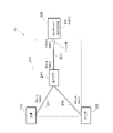
- FIG. 10 It is a block diagram which shows an example of the schematic structure of the displacement sensor 10 which concerns on each embodiment of this invention. It is a figure which shows typically the structure of the displacement sensor 11 which concerns on 1st Embodiment of this invention. It is a figure which shows a specific example of the optical fiber which has a taper part. It is a figure which shows the internal structure of the optical fiber which includes the taper part. It is a figure which shows the evaluation of the displacement sensor 11 shown in FIG. It is a figure which shows the relationship between a sensor head waveform and a spectroscope waveform, and a light-receiving waveform.
- FIG. 1 is a configuration diagram showing an example of a schematic configuration of a displacement sensor 10 according to each embodiment of the present invention.
- the displacement sensor 10 includes a controller 100, a light guide unit 200, and a sensor head 300, and measures a distance to a measurement object TA by using a cofocal optical system.
- the controller 100 includes a light source 110, a spectroscope 120, and a processing unit 130, and the spectroscope 120 further includes a collimator lens 121, a diffraction grating 122, an adjustment lens 123, and a light receiving element 124.
- the light guide unit 200 is arranged between the controller 100 and the sensor head 300, and has, for example, a first optical fiber 210, a second optical fiber 220, a third optical fiber 230, and an optical coupler 240. Propagate light. A part of the light guide unit 200 may be housed in the controller 100.
- the sensor head 300 is configured to be detachably attached to the controller 100 via the light guide unit 200, and has, for example, a diffractive lens 310 and an objective lens 320.
- the light source 110 outputs, for example, white light to the first optical fiber 210.
- the light source 110 may adjust the amount of white light based on the command of the processing unit 130.
- the light emitted by the light source 110 is not limited to white light as long as it is light containing a plurality of wavelength components and includes a wavelength range that covers the measurement distance range required for the displacement sensor 10. do not have.
- One end of the first optical fiber 210 is optically connected to the light source 110, one end of the second optical fiber 220 is optically connected to the sensor head 300, and the third optical fiber 230 is. , One end thereof is optically connected to the spectroscope 120.
- the other end of the first optical fiber 210, the other end of the third optical fiber 230, and the other end of the second optical fiber 220 are optically coupled via an optical coupler 240.
- the optical coupler 240 transmits the light (irradiation light) incident from the first optical fiber 210 to the second optical fiber 220, and divides the light (reflected light) incident from the second optical fiber 220 into the first. It is transmitted to the optical fiber 210 and the third optical fiber 230, respectively. The light transmitted from the second optical fiber 220 to the first optical fiber 210 by the optical coupler 240 is terminated by the light source 110.
- White light output from the light source 110 is incident on the sensor head 300 via the first optical fiber 210, the optical coupler 240, and the second optical fiber 220.
- the sensor head 300 is a diffractive lens 310 that causes chromatic aberration along the optical axis direction of white light emitted from the end face of the second optical fiber 220, and an objective lens that collects the light that causes chromatic aberration on the measurement object TA. It accommodates 320 and irradiates the measurement object TA with the light that causes the chromatic aberration.
- the light 410 of the first wavelength, the light 420 of the second wavelength, and the light 430 of the third wavelength are used in the order of relatively short focal lengths.
- the light 420 of the second wavelength is focused on the surface of the object TA to be measured (second focal position), while the light 410 of the first wavelength is focused on the front side of the object TA to be measured (first focal position).
- the light 430 of the third wavelength is in focus behind the measurement object TA (third focal position).
- the light reflected on the surface of the measurement object TA is collected by the objective lens 320, collected through the diffractive lens 310, and returned to the core of the second optical fiber 220.
- Most of the reflected light of the second wavelength light 420 is incident on the second optical fiber 220 because the light 420 of the second wavelength is focused on the end face of the second optical fiber 220, but the light of other wavelengths is the second optical fiber 220.
- the end face of the light is out of focus, and most of it does not enter the second optical fiber 220.
- the reflected light incident on the second optical fiber 220 is transmitted to the third optical fiber 230 via the optical coupler 240 and input to the spectroscope 120.
- the reflected light incident on the second optical fiber 220 is also transmitted to the first optical fiber 210 via the optical coupler 240, but is terminated by the light source 110.
- the spectroscope 120 acquires the reflected light reflected by the measurement object TA and collected by the sensor head 300 via the second optical fiber 220, the optical coupler 240, and the third optical fiber 230, and the spectrum of the reflected light is obtained. To measure.
- the spectroscope 120 includes a collimeter lens 121 that collects the reflected light emitted from the third optical fiber 230, a diffraction grid 122 that disperses the reflected light, an adjustment lens 123 that collects the dispersed reflected light, and the dispersed reflected light. Includes a light receiving element 124 that receives light.
- the processing unit 130 detects the position of the measurement target TA based on the light receiving amount distribution signal indicating the wavelength and the light amount of the light received by the light receiving element 124. Specifically, the position of the measurement target TA can be measured by detecting the peak of the wavelength in the received light waveform with the spectroscope 120, but in the case of this example, among the light reflected by the measurement target TA.
- the light 420 of the second wavelength which is focused on the optical fiber, appears as a peak in the spectroscope 120, and the position of the measurement target TA can be detected.
- the amount of light received that affects the measurement speed of the displacement sensor 10 is affected by the coupling efficiency of the sensor head 300, it is considered that it can be improved by setting a large numerical aperture (NA) of the diffractive lens 310. This is contrary to the measures for improving the movement resolution.
- the waveform of the light focused by the sensor head 300 (hereinafter, may be referred to as “sensor head waveform” or the like) is combined with the device characteristic waveform (hereinafter, “spectrometer waveform”) caused by a device such as the spectroscope 120.
- the light receiving waveform light receiving amount distribution signal
- the light receiving amount may decrease.
- the inventors of the present invention have found that the second optical fiber 220 connected to the sensor head 300 has a larger core diameter than the third optical fiber 230 connected to the spectroscope 120.
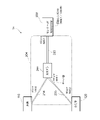
- FIG. 2 is a diagram schematically showing the configuration of the displacement sensor 11 according to the first embodiment of the present invention.
- the displacement sensor 11 includes a light source 110, a spectroscope 120, and a sensor head 300, and light is propagated through the light guide unit 201, respectively.
- the light guide unit 201 includes a first optical fiber 211, a second optical fiber 221 and a third optical fiber 231 and an optical coupler 241.
- Each optical fiber has the following core diameter and numerical aperture (NA). Has.
- a tapered portion whose core diameter changes continuously is provided.
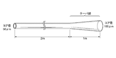
- FIG. 3A is a diagram showing a specific example of an optical fiber provided with a tapered portion
- FIG. 3B is a diagram showing an internal structure of the optical fiber provided with the tapered portion.
- the tapered portion is formed by continuously and gradually changing the diameter of the optical fiber over a range of 1 m out of the 3 m optical fiber.
- a tapered portion is formed at the end portion of the optical fiber, but the present invention is not limited to this. May have a cylindrical shape of 50 ⁇ m and 100 ⁇ m, respectively.
- the range in which the tapered portion is formed is not limited to about 1/3 or 1 m of the length of the optical fiber, and may be appropriately set according to the core diameters at both ends and the like.
- the half-price width of the sensor head 300 is affected by the core diameter of the optical fiber on the sensor head 300 side and the NA of the diffractive lens 310, and the moving resolution is affected by the half-price width and spot diameter of the sensor head 300.
- the NA of the diffractive lens 310 is the same as that of the comparative example.
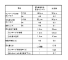
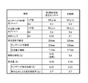
- the displacement sensor 11 has a core diameter of 100 ⁇ m of the optical fiber on the sensor head 300 side, which is twice that of the comparative example, but the spot diameter is also doubled accordingly. As a result, the displacement sensor 11 is able to suppress a decrease in movement resolution as compared with the comparative example.
- the half-value width of the light receiving waveform (light receiving amount distribution signal), the waveform of the light focused by the sensor head 300 (sensor head waveform), and the device characteristic waveform (spectrometer waveform) caused by a device such as the spectroscope 120.
- the half-value width of the light receiving waveform (light receiving amount distribution signal)
- the waveform of the light focused by the sensor head 300 (sensor head waveform)
- the device characteristic waveform (spectrometer waveform) caused by a device such as the spectroscope 120.
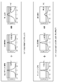
- FIG. 5 is a diagram showing the relationship between the sensor head waveform and the spectroscope waveform and the received light waveform.
- each waveform shows the amount of light on the vertical axis and the wavelength on the horizontal axis.
- the received light waveform is obtained by a convolution operation in which the spectroscope waveform is synthesized with the sensor head waveform, and the half width of the received light waveform is approximately the half width of the sensor head waveform and the spectroscope waveform. Calculated based on the full width at half maximum.
- the full width at half maximum is the length (width) of the intersection of the light receiving amount line of 50% of the light receiving amount peak (maximum value) and the light receiving amount distribution signal, and is an index showing the degree of spread of the Gaussian distribution. be. Since the received light waveform appears as a peak at the wavelength of the light focused on the measurement target TA, the position of the measurement target TA can be appropriately measured by the peak appearing more clearly. .. That is, if the full width at half maximum is small, it can be said that the measurement accuracy is high.
- the amount of light received may decrease in the relationship between the half-value width of the sensor head waveform and the half-value width of the spectroscope waveform.
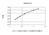
- FIG. 6 is a diagram showing the relationship between the half-value width of the sensor head waveform, the half-value width of the spectroscope waveform, and the amount of received light.
- the amount of received light decreases as the half-value width of the sensor head waveform / half-value width of the spectroscope waveform decreases.
- FIG. 5B when the half width of the sensor head waveform is reduced, the half width of the received light waveform is reduced and the half width of the sensor head waveform / half width of the spectroscope waveform is also reduced. As a result, the amount of light received is significantly reduced.
- the displacement sensor 11 since the light guide portion 201 includes the second optical fiber 221 provided with the tapered portion, the optical fiber connected to the sensor head 300 is It has a larger core diameter than the optical fiber connected to the spectroscope 120. As a result, the amount of light received can be significantly increased while suppressing the decrease in moving resolution. As a result, the displacement sensor 11 can improve the measurement speed while suppressing the deterioration of the measurement accuracy.
- the optical fiber used in the present embodiment may be a single core having a single core or a multi-core having a plurality of cores, but the above may be applied even when the single core is applied. Since the effect is obtained, it also leads to the reduction of the cost burden due to the application of multi-core.
- FIG. 7 is a diagram schematically showing the configuration of the displacement sensor 12 according to the second embodiment of the present invention.
- the displacement sensor 12 has a different NA of the diffractive lens 310 in the sensor head 300 as compared with the displacement sensor 11 according to the first embodiment.
- the NA of the diffractive lens 310 is 0.05.
- the NA of the diffractive lens 310 with respect to the NA of the optical fiber on the sensor head 300 side is 1/2, which is the same as the comparative example. Therefore, the displacement sensor 12 and the comparative example have the same coupling efficiency (ratio) of the sensor head, and suppress the decrease in the amount of received light.
- the core diameter of the optical fiber on the sensor head 300 side is 100 ⁇ m, which is twice that of the comparative example, and the NA of the diffractive lens 310 is 0.05, which is 1/2 that of the comparative example. Therefore, the half price width of the sensor head 300 is the same as that of the comparative example. Further, since the core diameter of the optical fiber on the sensor head 300 side is doubled and the spot diameter is doubled as compared with the comparative example, the moving resolution is greatly improved by averaging within the spot.
- the diffractive lens of the sensor head 300 has the same configuration as the light guide unit 201 in the displacement sensor 11 according to the first embodiment.
- the NA is set smaller than the NA of the optical fiber on the sensor head 300 side. This makes it possible to significantly improve the moving resolution while suppressing a decrease in the amount of received light. As a result, the displacement sensor 12 can improve the measurement accuracy while suppressing the decrease in the measurement speed.
- FIG. 9 is a diagram schematically showing the configuration of the displacement sensor 13 according to the third embodiment of the present invention.
- the displacement sensor 13 includes a light source 110, a spectroscope 120, and a sensor head 300, and light is propagated through the light guide unit 203, respectively.
- the light guide unit 203 includes a first optical fiber 213, a second optical fiber 223, a third optical fiber 233, and an optical coupler 243, and each optical fiber has the following core diameter and numerical aperture (NA).
- NA numerical aperture
- the optical fiber provided with the tapered portion is the third optical fiber 233, that is, the first embodiment shown in FIG. It is different from the displacement sensor 11 (the second optical fiber 221 is provided with a tapered portion).
- the first optical fiber 213 has a core diameter twice as large as that of the first optical fiber 211 in the displacement sensor 11 according to the first embodiment shown in FIG. 2, so that the cross-sectional area is quadrupled.
- NA is 1/2.
- the amount of light output from the light source 110 and propagated by the first optical fiber 213 is the same as that of the displacement sensor 11 according to the first embodiment.
- the optical coupler 243 is a coupler that connects two optical fibers having a core diameter of 100 ⁇ m.
- the third optical fiber 233 is configured to have a tapered portion so that the optical fiber connected to the sensor head 300 has a larger core diameter than the optical fiber connected to the spectroscope 120. ..
- the displacement sensor 13 can significantly increase the amount of light received (5.5 times) while suppressing the decrease in moving resolution. As a result, the displacement sensor 13 can improve the measurement speed while suppressing the deterioration of the measurement accuracy.
- the displacement is dislocated.
- the sensor 13 has the same effect as the displacement sensor 12 according to the second embodiment.
- the displacement sensor 13 can significantly improve the moving resolution (twice) while suppressing a decrease in the amount of received light. As a result, it is possible to improve the measurement accuracy while suppressing the decrease in the measurement speed.
- FIG. 10 is a diagram schematically showing the configuration of the displacement sensor 14 according to the fourth embodiment of the present invention.
- the displacement sensor 14 includes a light source 110, a spectroscope 120, and a sensor head 300, and light is propagated through the light guide unit 204, respectively.
- the light guide portion 204 has a first optical fiber 214, a second optical fiber 223, a third optical fiber 233, and an optical coupler 244, and each optical fiber has the following core diameter and numerical aperture (NA).
- NA numerical aperture
- the optical fiber provided with the tapered portion is the third optical fiber 233, that is, the first embodiment shown in FIG. It is different from the displacement sensor 11 (the second optical fiber 221 is provided with a tapered portion).
- the displacement sensor 14 according to the fourth embodiment is the same as the displacement sensor 13 according to the third embodiment.
- the first optical fiber 214 is different from the first optical fiber 213 of the displacement sensor 13 according to the third embodiment shown in FIG. 9, in the displacement sensor 11 according to the first embodiment shown in FIG. It is the same as the first optical fiber 211.
- the optical coupler 244 is a coupler that couples an optical fiber having a core diameter of 50 ⁇ m and an optical fiber having a core diameter of 100 ⁇ m.
- the optical fiber connected to the sensor head 300 has a larger core diameter than the optical fiber connected to the spectroscope 120, and in this respect. Is the same as the displacement sensor 13 of the third embodiment, and has the same effect as the displacement sensor 13.
- the displacement sensor 14 is the displacement sensor 11 according to the first embodiment as shown in FIG.
- the same effect can be achieved, and the amount of light received can be significantly increased (5.5 times) while suppressing the decrease in moving resolution.
- the displacement sensor 14 can improve the measurement speed while suppressing the deterioration of the measurement accuracy.
- the displacement sensor 14 has the same effect as the displacement sensor 12 according to the second embodiment as shown in FIG. It is possible to significantly improve the moving resolution (twice) while suppressing the decrease in the amount of received light. As a result, the displacement sensor 14 can improve the measurement accuracy while suppressing the decrease in the measurement speed.
- the optical fiber connected to the sensor head 300 by providing a tapered portion in any of the optical fibers included in the light guide portion is connected to the spectroscope 120.
- it has a core diameter larger than that of the optical fiber to be connected, it may be realized by an optical coupler.
- the core diameter of the second optical fiber connecting the optical coupler and the sensor head 300 is 100 ⁇ m
- the core diameter of the second optical fiber connecting the optical coupler and the spectroscope 120 is 50 ⁇ m
- the core is formed by the optical coupler.
- a structure that absorbs the difference in diameter may be used.
- Sensor head (300) and A spectroscope (120) for acquiring the reflected light reflected by the measurement object and collected by the sensor head via the light guide unit and measuring the spectrum of the reflected light is provided.
- the optical fiber (220,221,223) connected to the sensor head has a larger core diameter than the optical fiber (230,231,233) connected to the spectroscope.
Landscapes
- Physics & Mathematics (AREA)
- General Physics & Mathematics (AREA)
- Electromagnetism (AREA)
- Engineering & Computer Science (AREA)
- Radar, Positioning & Navigation (AREA)
- Remote Sensing (AREA)
- Length Measuring Devices By Optical Means (AREA)
Abstract
Description
図1は、本発明の各実施形態に係る変位センサ10の概略構成の一例を示す構成図である。図1に示されるように、変位センサ10は、コントローラ100と、導光部200と、センサヘッド300とを備え、共焦点光学系を利用することによって計測対象物TAまでの距離を計測する。
ここで、変位センサ10の計測精度に関して、計測誤差に与える影響が大きい移動分解能について、説明する。移動分解能は、被写界深度及び平均化効果に影響されることから、光ファイバのコア径や回折レンズ310の開口数(以下、「NA(numerical aperture)」と称する場合もある。)を小さく設定すれば、改善すると考えられる。
図2は、本発明の第1実施形態に係る変位センサ11の構成を模式的に示す図である。図2において、変位センサ11は、光源110と分光器120とセンサヘッド300とを備え、それぞれ導光部201を介して光が伝搬される。導光部201は、第1光ファイバ211と、第2光ファイバ221と、第3光ファイバ231と、光カプラ241とを有し、各光ファイバは、以下のコア径及び開口数(NA)を有する。
第2光ファイバ221:コア径=50μm、NA=0.2(光カプラ241側)
:コア径=100μm、NA=0.1(センサヘッド300側)
第3光ファイバ231:コア径=50μm、NA=0.2
図4は、図2に示された変位センサ11の評価を示す図である。図4に示されるように、変位センサ11では、比較例(全てコア径=50μm及びNA=0.2の光ファイバ)と比べて、移動分解能の低下を抑止しつつ、受光量を大幅に増加させている(5.5倍)。
図7は、本発明の第2実施形態に係る変位センサ12の構成を模式的に示す図である。図7において、変位センサ12は、第1実施形態に係る変位センサ11と比べて、センサヘッド300における回折レンズ310のNAが異なる。本実施形態では、回折レンズ310のNA=0.05である。
図9は、本発明の第3実施形態に係る変位センサ13の構成を模式的に示す図である。図9において、変位センサ13は、光源110と分光器120とセンサヘッド300とを備え、それぞれ導光部203を介して光が伝搬される。導光部203は、第1光ファイバ213と、第2光ファイバ223と、第3光ファイバ233と、光カプラ243とを有し、各光ファイバは、以下のコア径及び開口数(NA)を有する。
第2光ファイバ223:コア径=100μm、NA=0.1
第3光ファイバ233:コア径=100μm、NA=0.1(光カプラ243側)
:コア径=50μm、NA=0.2(分光器120側)
センサヘッド300に収容される回折レンズ310について、NA=0.1であり、当該センサヘッド300に接続される第2光ファイバ223のNAと同一に設定される場合には、変位センサ13は、図4で示されたように第1実施形態に係る変位センサ11と同様の効果を奏する。
図10は、本発明の第4実施形態に係る変位センサ14の構成を模式的に示す図である。図10において、変位センサ14は、光源110と分光器120とセンサヘッド300とを備え、それぞれ導光部204を介して光が伝搬される。導光部204は、第1光ファイバ214と、第2光ファイバ223と、第3光ファイバ233と、光カプラ244とを有し、各光ファイバは、以下のコア径及び開口数(NA)を有する。
第2光ファイバ223:コア径=100μm、NA=0.1
第3光ファイバ233:コア径=100μm、NA=0.1(光カプラ244側)
:コア径=50μm、NA=0.2(分光器120側)
白色光を出力する光源(110)と、
少なくとも1つの光ファイバを含む導光部(200,201,202,203,204)と、
前記導光部を介して入射した前記白色光に対して、光軸方向に沿って色収差を生じさせる回折レンズ(310)を収容し、色収差を生じさせた光を計測対象物(TA)に照射するセンサヘッド(300)と、
前記計測対象物で反射されて前記センサヘッドにより集光された反射光を、前記導光部を介して取得し、前記反射光のスペクトルを計測する分光器(120)と、を備え、
前記センサヘッドに接続される光ファイバ(220,221,223)は、前記分光器に接続される光ファイバ(230,231,233)よりも大きいコア径を有する、
変位センサ(10,11,12,13,14)。
Claims (8)
- 白色光を出力する光源と、
少なくとも1つの光ファイバを含む導光部と、
前記導光部を介して入射した前記白色光に対して、光軸方向に沿って色収差を生じさせる回折レンズを収容し、色収差を生じさせた光を計測対象物に照射するセンサヘッドと、
前記計測対象物で反射されて前記センサヘッドにより集光された反射光を、前記導光部を介して取得し、前記反射光のスペクトルを計測する分光器と、を備え、
前記センサヘッドに接続される光ファイバは、前記分光器に接続される光ファイバよりも大きいコア径を有する、
変位センサ。 - 前記センサヘッドと前記分光器との間に配置される光ファイバは、コア径が連続的に変化するテーパ部を含む、
請求項1に記載の変位センサ。 - 前記導光部は、
前記光源と接続される第1光ファイバと、
前記センサヘッドと接続される第2光ファイバと、
前記分光器と接続される第3光ファイバと、
前記第1光ファイバ、前記第2光ファイバ及び前記第3光ファイバが接続される光カプラと、を含む、
請求項1又は2に記載の変位センサ。 - 前記第2光ファイバは、コア径が連続的に変化するテーパ部を含む、
請求項3に記載の変位センサ。 - 前記第3光ファイバは、コア径が連続的に変化するテーパ部を含む、
請求項3に記載の変位センサ。 - 前記第2光ファイバは、前記第3光ファイバよりも大きいコア径を有する、
請求項3に記載の変位センサ。 - 前記センサヘッドに接続される光ファイバは、前記回折レンズと同一の開口数を有する、
請求項1から6のいずれか一項に記載の変位センサ。 - 前記センサヘッドに接続される光ファイバは、前記回折レンズよりも大きい開口数を有する、
請求項1から6のいずれか一項に記載の変位センサ。
Priority Applications (1)
| Application Number | Priority Date | Filing Date | Title |
|---|---|---|---|
| CN202180082421.1A CN116601459B (zh) | 2021-01-08 | 2021-03-02 | 位移传感器 |
Applications Claiming Priority (2)
| Application Number | Priority Date | Filing Date | Title |
|---|---|---|---|
| JP2021-002272 | 2021-01-08 | ||
| JP2021002272A JP7551058B2 (ja) | 2021-01-08 | 2021-01-08 | 変位センサ |
Publications (1)
| Publication Number | Publication Date |
|---|---|
| WO2022149290A1 true WO2022149290A1 (ja) | 2022-07-14 |
Family
ID=82357883
Family Applications (1)
| Application Number | Title | Priority Date | Filing Date |
|---|---|---|---|
| PCT/JP2021/007847 Ceased WO2022149290A1 (ja) | 2021-01-08 | 2021-03-02 | 変位センサ |
Country Status (3)
| Country | Link |
|---|---|
| JP (1) | JP7551058B2 (ja) |
| CN (1) | CN116601459B (ja) |
| WO (1) | WO2022149290A1 (ja) |
Families Citing this family (1)
| Publication number | Priority date | Publication date | Assignee | Title |
|---|---|---|---|---|
| JP2024063972A (ja) * | 2022-10-27 | 2024-05-14 | 株式会社東京精密 | 測定装置 |
Citations (3)
| Publication number | Priority date | Publication date | Assignee | Title |
|---|---|---|---|---|
| JP2012208102A (ja) * | 2011-03-14 | 2012-10-25 | Omron Corp | 共焦点計測装置 |
| JP2017102067A (ja) * | 2015-12-03 | 2017-06-08 | オムロン株式会社 | 光学計測装置 |
| JP2018146279A (ja) * | 2017-03-02 | 2018-09-20 | オムロン株式会社 | 共焦点計測装置 |
Family Cites Families (2)
| Publication number | Priority date | Publication date | Assignee | Title |
|---|---|---|---|---|
| EP1739394A1 (fr) * | 2005-06-30 | 2007-01-03 | Talltec Technologies Holdings S.A. | Capteur de chocs à fibre optique multimode fonctionnant sur le principe du couplage entre modes guidés par la fibre |
| CN110196020B (zh) * | 2014-06-27 | 2021-08-10 | 株式会社基恩士 | 多波长共焦测量装置 |
-
2021
- 2021-01-08 JP JP2021002272A patent/JP7551058B2/ja active Active
- 2021-03-02 CN CN202180082421.1A patent/CN116601459B/zh active Active
- 2021-03-02 WO PCT/JP2021/007847 patent/WO2022149290A1/ja not_active Ceased
Patent Citations (3)
| Publication number | Priority date | Publication date | Assignee | Title |
|---|---|---|---|---|
| JP2012208102A (ja) * | 2011-03-14 | 2012-10-25 | Omron Corp | 共焦点計測装置 |
| JP2017102067A (ja) * | 2015-12-03 | 2017-06-08 | オムロン株式会社 | 光学計測装置 |
| JP2018146279A (ja) * | 2017-03-02 | 2018-09-20 | オムロン株式会社 | 共焦点計測装置 |
Also Published As
| Publication number | Publication date |
|---|---|
| JP2022107367A (ja) | 2022-07-21 |
| JP7551058B2 (ja) | 2024-09-17 |
| CN116601459B (zh) | 2025-09-30 |
| CN116601459A (zh) | 2023-08-15 |
Similar Documents
| Publication | Publication Date | Title |
|---|---|---|
| US10267621B2 (en) | Confocal displacement sensor | |
| US8212997B1 (en) | Chromatic confocal point sensor optical pen with extended measuring range | |
| KR102115498B1 (ko) | 공초점 계측 장치 | |
| JP5060678B2 (ja) | 光学式変位計 | |
| US11231270B2 (en) | Optical measuring device | |
| US20140347660A1 (en) | Metrological apparatus | |
| US7286225B2 (en) | Optical fiber type spectroscope and spectroscope system equipped therewith | |
| JP7551058B2 (ja) | 変位センサ | |
| JP7296239B2 (ja) | 光学計測装置、光学計測方法、及び光学計測プログラム | |
| US11965729B2 (en) | Confocal sensor | |
| KR20210077738A (ko) | 광학 계측 장치 및 광학 계측 방법 | |
| JP2016038213A (ja) | 外形寸法測定装置及び外形寸法測定方法 | |
| KR20190088386A (ko) | 광학 계측 장치 및 광학 계측 방법 | |
| CN120195084A (zh) | 一种多激光光谱流式细胞仪光学系统 |
Legal Events
| Date | Code | Title | Description |
|---|---|---|---|
| 121 | Ep: the epo has been informed by wipo that ep was designated in this application |
Ref document number: 21917515 Country of ref document: EP Kind code of ref document: A1 |
|
| WWE | Wipo information: entry into national phase |
Ref document number: 202180082421.1 Country of ref document: CN |
|
| NENP | Non-entry into the national phase |
Ref country code: DE |
|
| 122 | Ep: pct application non-entry in european phase |
Ref document number: 21917515 Country of ref document: EP Kind code of ref document: A1 |
|
| WWG | Wipo information: grant in national office |
Ref document number: 202180082421.1 Country of ref document: CN |