WO2022145406A1 - Gas-liquid separation device - Google Patents
Gas-liquid separation device Download PDFInfo
- Publication number
- WO2022145406A1 WO2022145406A1 PCT/JP2021/048474 JP2021048474W WO2022145406A1 WO 2022145406 A1 WO2022145406 A1 WO 2022145406A1 JP 2021048474 W JP2021048474 W JP 2021048474W WO 2022145406 A1 WO2022145406 A1 WO 2022145406A1
- Authority
- WO
- WIPO (PCT)
- Prior art keywords
- pipe
- gas
- liquid
- swirling flow
- flow generating
- Prior art date
Links
- 239000007788 liquid Substances 0.000 title claims abstract description 145
- 238000000926 separation method Methods 0.000 title claims abstract description 52
- 239000012530 fluid Substances 0.000 claims abstract description 54
- 238000004891 communication Methods 0.000 claims abstract description 35
- 238000011144 upstream manufacturing Methods 0.000 claims abstract description 12
- 230000002093 peripheral effect Effects 0.000 claims description 49
- 230000005484 gravity Effects 0.000 claims description 5
- XLYOFNOQVPJJNP-UHFFFAOYSA-N water Substances O XLYOFNOQVPJJNP-UHFFFAOYSA-N 0.000 description 23
- 238000002485 combustion reaction Methods 0.000 description 11
- 125000006850 spacer group Chemical group 0.000 description 4
- 239000010419 fine particle Substances 0.000 description 3
- 238000012986 modification Methods 0.000 description 3
- 230000004048 modification Effects 0.000 description 3
- 239000003054 catalyst Substances 0.000 description 2
- 238000001816 cooling Methods 0.000 description 2
- 238000010586 diagram Methods 0.000 description 2
- 238000000746 purification Methods 0.000 description 2
- 239000003507 refrigerant Substances 0.000 description 2
- 238000004804 winding Methods 0.000 description 2
- 238000007792 addition Methods 0.000 description 1
- 239000000498 cooling water Substances 0.000 description 1
- 238000006073 displacement reaction Methods 0.000 description 1
- 230000000694 effects Effects 0.000 description 1
- 238000001914 filtration Methods 0.000 description 1
- 239000000463 material Substances 0.000 description 1
- 238000000034 method Methods 0.000 description 1
- 230000000149 penetrating effect Effects 0.000 description 1
- 238000005057 refrigeration Methods 0.000 description 1
- 238000009423 ventilation Methods 0.000 description 1
Images


Classifications
-
- B—PERFORMING OPERATIONS; TRANSPORTING
- B01—PHYSICAL OR CHEMICAL PROCESSES OR APPARATUS IN GENERAL
- B01D—SEPARATION
- B01D45/00—Separating dispersed particles from gases or vapours by gravity, inertia, or centrifugal forces
- B01D45/12—Separating dispersed particles from gases or vapours by gravity, inertia, or centrifugal forces by centrifugal forces
- B01D45/14—Separating dispersed particles from gases or vapours by gravity, inertia, or centrifugal forces by centrifugal forces generated by rotating vanes, discs, drums or brushes
-
- F—MECHANICAL ENGINEERING; LIGHTING; HEATING; WEAPONS; BLASTING
- F02—COMBUSTION ENGINES; HOT-GAS OR COMBUSTION-PRODUCT ENGINE PLANTS
- F02M—SUPPLYING COMBUSTION ENGINES IN GENERAL WITH COMBUSTIBLE MIXTURES OR CONSTITUENTS THEREOF
- F02M26/00—Engine-pertinent apparatus for adding exhaust gases to combustion-air, main fuel or fuel-air mixture, e.g. by exhaust gas recirculation [EGR] systems
- F02M26/13—Arrangement or layout of EGR passages, e.g. in relation to specific engine parts or for incorporation of accessories
- F02M26/35—Arrangement or layout of EGR passages, e.g. in relation to specific engine parts or for incorporation of accessories with means for cleaning or treating the recirculated gases, e.g. catalysts, condensate traps, particle filters or heaters
-
- F—MECHANICAL ENGINEERING; LIGHTING; HEATING; WEAPONS; BLASTING
- F02—COMBUSTION ENGINES; HOT-GAS OR COMBUSTION-PRODUCT ENGINE PLANTS
- F02M—SUPPLYING COMBUSTION ENGINES IN GENERAL WITH COMBUSTIBLE MIXTURES OR CONSTITUENTS THEREOF
- F02M35/00—Combustion-air cleaners, air intakes, intake silencers, or induction systems specially adapted for, or arranged on, internal-combustion engines
- F02M35/10—Air intakes; Induction systems
- F02M35/10209—Fluid connections to the air intake system; their arrangement of pipes, valves or the like
- F02M35/10222—Exhaust gas recirculation [EGR]; Positive crankcase ventilation [PCV]; Additional air admission, lubricant or fuel vapour admission
-
- F—MECHANICAL ENGINEERING; LIGHTING; HEATING; WEAPONS; BLASTING
- F02—COMBUSTION ENGINES; HOT-GAS OR COMBUSTION-PRODUCT ENGINE PLANTS
- F02M—SUPPLYING COMBUSTION ENGINES IN GENERAL WITH COMBUSTIBLE MIXTURES OR CONSTITUENTS THEREOF
- F02M35/00—Combustion-air cleaners, air intakes, intake silencers, or induction systems specially adapted for, or arranged on, internal-combustion engines
- F02M35/10—Air intakes; Induction systems
- F02M35/10242—Devices or means connected to or integrated into air intakes; Air intakes combined with other engine or vehicle parts
- F02M35/10262—Flow guides, obstructions, deflectors or the like
Definitions
- the present invention is an invention relating to a gas-liquid separation device that separates a gas and a liquid contained in a gas-liquid two-phase fluid.
- the swirling flow generating member has a wing portion that extends spirally around the central axis of the pipe member.
- the tip of the wing portion in the pipe radial direction is continuous over the entire circumference of the pipe member when the pipe member is viewed from the axial direction, and a gap extending in the axial direction cannot occur between the adjacent wing portions. Further, the entire length of the wing portion is in contact with the inner peripheral surface of the pipe.
- the liquid when the flow velocity is low, the liquid does not become fine particles, but naturally separates from the gas and becomes water droplets adhering to the inner peripheral surface of the pipe before swirling.
- the liquid that has become water droplets flows inside the pipe member along the pipe axis direction due to the flow of gas, but the flow is obstructed because the blade portion of the swirling flow generating member is in contact with the inner peripheral surface of the pipe. Therefore, it is necessary to provide a drainage pipe at a position upstream of the swirling flow generating member in the flow direction of the gas-liquid two-phase fluid, and to guide water droplets to the water storage tank before flowing into the arrangement region of the swirling flow generating member.
- the present invention has been made by paying attention to the above problem, and provides a gas-liquid separation device capable of collecting a liquid at a position downstream of a swirling flow generating member regardless of the flow velocity of the gas-liquid two-phase fluid.
- the purpose is to do.
- the gas-liquid separation device of the present invention includes a pipe member through which a gas-liquid two-phase fluid in which a gas and a liquid are mixed flows, and a swirling flow generating member arranged inside the pipe member.
- the gas-liquid two-phase fluid is swirled by the swirling flow generating member to separate the gas and the liquid.
- the swirling flow generating member extends spirally around the central axis of the pipe member, and when the pipe member is viewed from the axial direction, the tip in the pipe radial direction extends over the entire circumference of the pipe member. It has a continuous wing.
- a bulging portion extending in the axial direction on the inner peripheral surface of the pipe member between the pipe member and the swirling flow generating member, a first upstream portion of the swirling flow generating member is formed.
- a communication portion is provided that communicates the space with the second space downstream of the swirling flow generating member.
- the pipe member when the pipe member is viewed from the axial direction, even if the tip of the blade portion in the pipe radial direction of the swirling flow generating member is continuous over the entire circumference of the pipe member, the gas-liquid two-phase Regardless of the flow velocity of the fluid, the liquid can be collected at a position downstream of the swirling flow generating member.
- FIG. 3 is an overall system diagram showing an exhaust gas return system of an internal combustion engine to which the gas-liquid separation device of Example 1 is applied. It is sectional drawing which shows the gas-liquid separation apparatus of Example 1.
- FIG. It is a perspective view which shows the swirling flow generating member of Example 1.
- FIG. It is a side view which shows the swirling flow generating member of Example 1.
- FIG. FIG. 2 is a sectional view taken along the line AA shown in FIG. It is explanatory drawing which shows the flow of the gas-liquid two-phase fluid at the time of high flow velocity in the gas-liquid separation apparatus of Example 1.
- FIG. It is explanatory drawing which shows the flow of the gas-liquid two-phase fluid at a low flow rate in the gas-liquid separation apparatus of Example 1.
- FIG. 1 It is sectional drawing of the main part which shows the 1st modification of the gas-liquid separation apparatus of Example 1.
- FIG. It is sectional drawing of the main part which shows the 2nd modification of the gas-liquid separation apparatus of Example 1.
- FIG. 1 It is sectional drawing of the main part which shows the 3rd modification of the gas-liquid separation apparatus of Example 1.
- FIG. 1 is an overall system diagram showing an exhaust recirculation system S of an internal combustion engine 1 to which the gas-liquid separation device 16 of the first embodiment is applied.
- the gas-liquid separation device 16 of the first embodiment is applied to the exhaust recirculation system S of the internal combustion engine 1 shown in FIG.
- the internal combustion engine 1 shown in FIG. 1 is a diesel engine mounted on a vehicle as a driving drive source for traveling, and has four cylinders (not shown).
- An intake passage 2 and an exhaust passage 3 are connected to each cylinder.
- the intake passage 2 has an intake port 2a formed at an end thereof, and in order from the intake port 2a side, an air cleaner 4 for intake filtration, a compressor 5a of a turbocharger 5, an intercooler 6 for cooling the intake air, and an intake air amount.
- a throttle valve 7 is provided for adjusting the speed.
- the exhaust passage 3 is provided with a turbine 5b of the turbocharger 5, an exhaust purification catalyst 8 for purifying the exhaust, and an exhaust throttle valve 9 for adjusting the exhaust flow rate, in order from the internal combustion engine 1 side.
- a muffler 10 is provided on the downstream side of the exhaust throttle valve 9, and an exhaust port 3a is formed ahead of the muffler 10.
- EGR exhaust Gas Recirculation
- exhaust gas recirculation is a technique (Exhaust Gas Recirculation) in which a part of the exhaust gas after combustion is taken out and taken in again in the internal combustion engine 1, and is also referred to as exhaust gas recirculation.
- the low-pressure EGR passage 11 connects the intake passage 2 upstream of the compressor 5a and the exhaust passage 3 downstream of the exhaust purification catalyst 8.
- the high-pressure EGR passage 12 connects the intake passage 2 downstream of the compressor 5a and the exhaust passage 3 upstream of the turbine 5b.
- the low-pressure EGR passage 11 includes an EGR cooler 13 for cooling the exhaust gas guided to the intake passage 2, and a low-pressure EGR valve 14 for adjusting the flow rate of the exhaust gas recirculated to the intake passage 2 via the low-pressure EGR passage 11. And are provided.
- the high-pressure EGR passage 12 is provided with a high-pressure EGR valve 15 for adjusting the flow rate of the exhaust gas recirculated to the intake passage 2 via the high-pressure EGR passage 12.
- the exhaust gas can be recirculated without reducing the displacement of the turbocharger 5 through the turbine, and the NOx reduction effect is great.
- the EGR gas may generate condensed water when it is cooled by the EGR cooler 13 or mixed with air during cold weather. Therefore, in the exhaust gas recirculation system S of the first embodiment, the gas-liquid separation device is located at the downstream position of the low-pressure EGR valve 14 and at the upstream position of the compressor 5a of the turbocharger 5 (the position surrounded by the one-point chain line X in FIG. 1). 16 is installed, and the condensed water is collected and drained by the gas-liquid separation device 16.
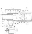
- FIG. 2 is a cross-sectional view showing the gas-liquid separation device 16 of the first embodiment.
- the gas-liquid separation device 16 of the first embodiment includes a pipe member 21, a swirling flow generating member 22, a water storage tank 23, and a bypass pipe 24.
- the pipe member 21 communicates with the intake port 2a and the low pressure EGR valve 14, and the other end communicates with the compressor 5a of the turbocharger 5, and the gas and the fine liquid (condensed water) are mixed.
- Exhaust gas (hereinafter referred to as "gas-liquid two-phase fluid”) flows.
- the pipe member 21 is arranged so that the central axis O1 is along the horizontal direction when mounted on the vehicle, and three tubular bodies of the first pipe 25, the second pipe 26, and the third pipe 27 are connected to each other. It is formed by that.
- the first pipe 25, the second pipe 26, and the third pipe 27 are the flow of the gas-liquid two-phase fluid from the upstream side in the flow direction of the gas-liquid two-phase fluid (the right side in FIG. 2, hereinafter referred to as “fluid inflow side”). They are connected in order toward the downstream side in the direction (left side in FIG. 2, hereinafter referred to as "fluid outflow side").
- the axial direction of the pipe member 21 (direction along the central axis O1 ) is referred to as “tube axial direction”, and the radial direction of the pipe member 21 (direction orthogonal to the central axis O1 ) is “. It is called “pipe radial direction”.
- the circumferential direction of the pipe member 21 (circumferential direction around the central axis O1 ) is referred to as “pipe circumferential direction”.
- the first pipe 25 is a straight pipe member in which the swirling flow generating member 22 is arranged inside. Inside the first pipe 25, there are a swirling region 22a in which the swirling flow generating member 22 is arranged, a tapered region 25b that gradually expands the inner diameter of the first pipe 25 toward the fluid outflow side, and a second pipe 26. A stepped portion 25c to be abutted against is formed.
- the tapered region 25b is formed on the fluid outflow side with respect to the swirling region 22a.
- the step portion 25c is formed on the fluid outflow side with respect to the tapered region 25b.
- the inner diameter of the first pipe 25 increases in the order of the swivel region 22a, the tapered region 25b, and the stepped portion 25c.
- a bulging portion 25d is formed on the inner peripheral surface 25a of the first pipe 25.
- the bulging portion 25d is formed by projecting (denting) a part of the inner peripheral surface 25a of the first pipe 25 outward in the pipe radial direction with a step, and exhibits a groove shape extending in the pipe axis direction. ing. Further, the bulging portion 25d extends from the end portion (not shown) on the fluid inflow side of the first pipe 25 to at least the end portion on the fluid outflow side of the swirling region 22a. Further, the bulging portion 25d has a predetermined width dimension W along the horizontal direction, and the central position 25e in the pipe circumferential direction is located below the vertical direction of the central axis O1 of the pipe member 21. ..
- the bulging portion 25d has a bottom surface 25f formed on a flat surface along the horizontal direction, and the depth H (distance from the inner peripheral surface 25a of the first pipe 25 to the bottom surface 25f of the bulging portion 25d) is a pipe.
- the central position 25e in the circumferential direction is the shallowest, and gradually becomes deeper toward both ends in the circumferential direction.
- the second pipe 26 is a T-shaped pipe member having a horizontal portion 26a connected to the first pipe 25 and a vertical portion 26b connected to the horizontal portion 26a in an orthogonal state.
- One end of the horizontal portion 26a can be inserted into the first pipe 25, and the horizontal portion 26a is in contact with the inner peripheral surface 25a of the first pipe 25 in a state of being inserted into the first pipe 25. Further, one end of the horizontal portion 26a is abutted against the step portion 25c.
- the axial direction of the horizontal portion 26a coincides with the central axis O1 of the pipe member 21 and extends in the horizontal direction.
- a drainage opening 26c is formed at the connecting portion between the horizontal portion 26a and the vertical portion 26b, and the horizontal portion 26a and the vertical portion 26b communicate with each other.
- the drainage opening 26c opens in the direction of gravity (below the vertical direction of the central axis O1), and the vertical portion 26b extends from the horizontal portion 26a along the direction of gravity.
- the liquid separated from the gas-liquid two-phase fluid flows down the vertical portion 26b through the drainage opening 26c due to its own weight.
- the vertical portion 26b is connected to the reduced portion 26d in which the intermediate portion is gradually narrowed toward the downward direction.
- the opening area of the tip opening 26e formed at the tip (lower end) of the reduced portion 26d is smaller than the opening area of the drainage opening 26c.
- the vertical portion 26b, the drainage opening 26c, the reduced portion 26d, and the tip opening 26e correspond to a drainage pipe.
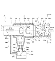
- the third pipe 27 can be inserted into the other end of the horizontal portion 26a of the second pipe 26, and when inserted into the second pipe 26, a gap ⁇ is formed between the third pipe 27 and the inner peripheral surface of the horizontal portion 26a. It is a straight pipe member set to the diameter dimension.
- a spacer 28 is fitted in the gap ⁇ .
- the spacer 28 has a cylindrical shape that surrounds the entire circumference of the outer peripheral surface of the third pipe 27, and comes into contact with the horizontal portion 26a of the second pipe 26 and the third pipe 27, respectively. That is, the other end of the horizontal portion 26a is closed by the spacer 28.
- the third pipe 27 is inserted into the second pipe 26 until one end 27a is located above the drainage opening 26c. Further, the third pipe 27 is formed with a vent 27b penetrating the peripheral surface at a position protruding from the second pipe 26. The second end 24b of the bypass pipe 24 is connected to the vent 27b.
- the water storage tank 23 has a tank body 23a installed below the vertical portion 26b of the second pipe 26.
- the tank body 23a has a first opening 23b formed on the upper surface, a second opening 23c formed on the side surface, and a drainage opening (not shown) formed on the bottom surface.
- the first opening 23b is connected to the tip opening 26e of the vertical portion 26b via the communication pipe 23d.
- the first end portion 24a of the bypass pipe 24 is connected to the second opening 23c.
- the drainage opening can be opened and closed as appropriate, and when the amount of liquid stored in the tank body 23a reaches a certain amount, the drainage opening can be opened and the stored liquid can be discharged to the outside of the tank.
- the bypass pipe 24 is a tubular body having both ends open, the first end 24a is connected to the second opening 23c formed in the tank body 23a, and the second end 24b is a ventilation formed in the third pipe 27. It is connected to the mouth 27b. As a result, the internal space of the tank body 23a communicates with the inside of the third pipe 27 via the bypass pipe 24.
- the swirling flow generating member 22 of the first embodiment is arranged in the swirling region 22a of the first pipe 25, defines the flow direction of the gas-liquid two-phase fluid flowing through the pipe member 21, and makes the gas-liquid two-phase fluid a swirling flow. do.
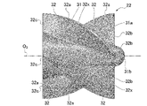
- the swirling flow generating member 22 includes a blade support portion 31 and a plurality of (here, four) blade portions 32 provided on the outer peripheral surface 31a of the blade support portion 31.
- the wing support portion 31 has a conical shape in which the tip portion 31b is formed on the R surface.
- the swirling flow generating member 22 is arranged in the swirling region 22a so that the tip portion 31b is directed toward the fluid inflow side and the outer diameter of the blade support portion 31 is gradually increased toward the fluid outflow side. Further, when the swirling flow generating member 22 is arranged in the swirling region 22a, the axial direction O 2 of the blade support portion 31 coincides with the central axis O 1 of the pipe member 21.
- Each of the plurality (four pieces) of the blade portions 32 protrudes in the pipe radial direction from the outer peripheral surface 31a of the blade support portion 31, and the axial direction O 2 of the blade support portion 31 is centered on the axial direction O 2 of the blade support portion 31. It is provided around the wing at equal intervals and surrounds it in a spiral shape.
- the axial direction O 2 of the blade support portion 31 coincides with the central axis O 1 of the pipe member 21. Therefore, each wing portion 32 extends while spirally curving around the central axis O1 of the pipe member 21 in a state where the swirling flow generating member 22 is arranged in the swirling region 22a.
- the tip 32a in the pipe radial direction of each wing portion 32 is the first except for the portion facing the bulging portion 25d formed in the first pipe 25. 1 Contact the inner peripheral surface 25a of the pipe 25 (inner peripheral surface of the pipe member 21).
- the surrounding angle ⁇ 1 of each blade portion 32 with respect to the blade support portion 31 is set to about 90 °.
- the “winding angle ⁇ 1” means the protrusion direction L1 of the end 32b on the fluid inflow side of the blade 32 and the blade when the swirling flow generating member 22 is viewed from the pipe axis direction.
- the end portion 32c on the fluid outflow side of the wing portion 32 is located on the fluid inflow side of the adjacent wing portions 32 when the swirling flow generating member 22 is viewed from the pipe axis direction. It overlaps the end portion 32b in the pipe axis direction. Due to the R shape generated at the ends 32b and 32c and the draft of the mold, the end 32b on the fluid inflow side and the end 32c on the fluid outflow side of the adjacent blades 32 are in the pipe axis direction. It may not overlap.
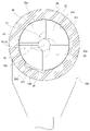
- the surrounding angle ⁇ 1 of the plurality (four pieces) of the wing portions 32 of the swirling flow generating member 22 is set to about 90 °, as shown in FIG. 4, when viewed from the pipe axis direction, the swirling flow generating member 22 has.
- the tip 32a of the wing portion 32 is continuous over the entire circumference of the pipe member 21. That is, when the swirling flow generating member 22 is viewed from the pipe axis direction, it is possible to surround the central axis O1 of the pipe member 21 with a locus along the tip 32a in the pipe radial direction of the wing portion 32. As a result, there can be no gap extending in the pipe axis direction between the facing side surfaces 32x of the adjacent blade portions 32.
- the swirling flow generating member is located between the inner peripheral surface 25a of the first pipe 25 which is the pipe member 21 and the tip end 32a of the wing portion 32 of the swirling flow generating member 22.
- a communication portion 34 is provided by forming a bulging portion 25d on the inner peripheral surface 25a of the first pipe 25 in which the 22 is arranged. That is, a communication portion 34 is formed on the inner peripheral surface 25a of the pipe member 21.
- the communication portion 34 extends along the pipe axis direction, and has a first space X (see FIG. 2) upstream (fluid inflow side) from the swirling region 22a in which the swirling flow generating member 22 is arranged, and the swirling flow generating member 22.
- the height of the communication portion 34 is set to match the depth H of the bulging portion 25d, to be the smallest at the central position in the pipe circumferential direction, and to be the largest at both ends in the pipe circumferential direction.
- the height of the communication portion 34 (depth H of the bulging portion 25d) is set to about 5% of the radial dimension of the pipe member 21 at the center position in the smallest pipe circumferential direction.
- the horizontal width of the communication portion 34 matches the width dimension W of the bulging portion 25d, and the circumference of the inner peripheral surface of the pipe member 21 (inner peripheral surface 25a of the first pipe 25) in the swivel region 22a. It is set to about 15% of the length.
- the condensed water becomes fine particles and flows in a mixed phase with the gas.
- the swirling flow generating member 22 is arranged inside the first pipe 25 of the pipe member 21.
- the swirling flow generating member 22 has a plurality of blade portions 32 that protrude in the pipe radial direction from the outer peripheral surface 31a of the blade support portion 31 and are spirally curved around the central axis O1 of the pipe member 21.
- the gas-liquid two-phase fluid flowing into the pipe member 21 flows along the wing portion 32 when passing through the swirling region 22a in which the swirling flow generating member 22 is installed, thereby flowing in the flow direction. Is specified, and it becomes a swirling flow that flows while swirling. Then, a liquid having a large mass is guided toward the inner peripheral surface 25a of the first pipe 25 by the centrifugal force generated by the swirling of the gas-liquid two-phase fluid. The liquid guided toward the inner peripheral surface 25a of the first pipe 25 adheres to the inner peripheral surface 25a of the first pipe 25, aggregates into water droplets, and is separated from the gas. On the other hand, the air from which the liquid is separated flows linearly along the pipe axis direction while swirling, flows from the first pipe 25 to the second pipe 26, and flows into the third pipe 27.
- the liquid that has become water droplets and separated from the gas passes through the tapered region 25b from the swirling region 22a while still adhering to the inner peripheral surface 25a of the first pipe 25 due to the flow of the swirling flow. Then, it flows to the second pipe 26.
- the liquid that has flowed into the second pipe 26 flows while adhering to the inner peripheral surface 26f of the second pipe 26, flows into the drainage opening 26c, and flows down the vertical portion 26b. After that, the liquid is discharged through the tip opening 26e and stored in the tank body 23a.
- the gas-liquid separation device 16 of the first embodiment when the gas-liquid two-phase fluid flows at a high flow velocity, the gas-liquid two-phase fluid is swirled by the swirling flow generating member 22, and the gas and the liquid are separated by the centrifugal force. Can be separated. Further, the gas-liquid separation device 16 of the first embodiment guides the liquid toward the inner peripheral surface 25a of the first pipe 25 and adheres the liquid to the inner peripheral surface 25a, thereby suppressing the re-scattering of the liquid and storing water. It can be collected in the tank 23.
- the liquid adhering to the inner peripheral surface 25a of the first pipe 25 cannot flow in a mixed phase with the gas, and heads toward the swirling region 22a while adhering to the inner peripheral surface 25a of the first pipe 25 due to the gas flow. And flow.
- the swirling flow generating member 22 has a blade portion 32 surrounding the blade support portion 31. Then, in the blade portion 32, the tip 32a in the pipe radial direction comes into contact with the inner peripheral surface 25a of the first pipe 25, and the winding angle ⁇ 1 with respect to the blade support portion 31 is set to about 90 °, from the pipe axis direction. When viewed, it is continuous over the entire circumference of the pipe member 21. Further, a communication portion 34 is formed between the inner peripheral surface 25a of the first pipe 25 and the wing portion 32 of the swirling flow generating member 22 by the bulging portion 25d formed in the first pipe 25 which is the pipe member 21. Has been done. The communication portion 34 extends along the pipe axis direction between the first pipe 25 and the swirling flow generating member 22, the first space X upstream of the swirling region 22a and the second space downstream of the swirling region 22a. Communicate with Y.
- the liquid (water droplet) separated from the gas before flowing into the swirling region 22a flows through the communication portion 34, flows horizontally inside the pipe member 21 with the central axis O1, and flows from the first space X to the second space X. It can flow into space Y. That is, the liquid adhering to the inner peripheral surface 25a of the first pipe 25 can smoothly pass through the swirling region 22a without being obstructed by the swirling flow generating member 22.
- the liquid that has passed through the swirling region 22a passes through the tapered region 25b and flows to the second pipe 26 while adhering to the inner peripheral surface 25a of the first pipe 25.
- the liquid that has flowed into the second pipe 26 flows while adhering to the inner peripheral surface 26f of the second pipe 26, flows into the drainage opening 26c, and flows down the vertical portion 26b. After that, it is discharged through the tip opening 26e and stored in the tank body 23a.
- the first The liquid can flow through the communication portion 34 provided between the inner peripheral surface 25a of the pipe 25 and the wing portion 32. Therefore, even if the tip 32a of the wing portion 32 is continuous over the entire circumference of the pipe member 21 when viewed from the pipe axis direction, the wing portion 32 does not obstruct the flow of the liquid and the swirling flow.
- the liquid can be collected on the fluid outflow side of the generating member 22. As a result, the liquid can be collected at a position downstream of the swirling flow generating member 22 regardless of the flow velocity of the gas-liquid two-phase fluid.
- the communication portion 34 is formed by a bulging portion 25d extending in the pipe axial direction formed on the inner peripheral surface 25a of the first pipe 25 which is the pipe member 21. .. Therefore, it is not necessary to form a partial notch, a dent, or the like at the tip 32a of the wing portion 32 of the swirling flow generating member 22, and the swirling flow generating member 22 can be easily formed.
- the bulging portion 25d formed in the first pipe 25 forming the communication portion 34 has a groove shape extending in the pipe axis direction. Therefore, the shape of the communicating portion 34 can be easily set to a desired shape by adjusting the depth H of the bulging portion 25d and the width dimension W in the horizontal direction.
- the bulging portion 25d is formed on a part of the inner peripheral surface 25a of the first pipe 25. That is, the width dimension W of the bulging portion 25d is shorter than the circumferential length of the inner peripheral surface 25a. Therefore, the communication portion 34 is a space formed in a part of the pipe circumferential direction between the inner peripheral surface 25a of the first pipe 25 and the wing portion 32. As a result, the tip 32a of the wing portion 32 comes into contact with the inner peripheral surface 25a of the first pipe 25 except for the portion facing the communication portion 34. Therefore, the swirling flow generating member 22 can be supported by the pipe member 21, and the strength of the swirling flow generating member 22 against vibration can be secured.
- the central position of the communication portion 34 in the pipe circumferential direction is the pipe member when viewed from the pipe axial direction. It is located below the central axis O1 of 21 in the direction of gravity. As a result, the liquid that has flowed down to the lower part of the pipe member 21 due to its own weight can flow into the communication portion 34, so that the liquid can be smoothly collected.
- the central position (central position 25e ) of the communication portion 34 in the pipe circumferential direction is located below the vertical direction of the central axis O1 of the pipe member 21. Therefore, the liquid that has flowed down to the lower part of the pipe member 21 due to gravity can surely flow into the communication portion 34.
- a gap ⁇ is formed between the second pipe 26 and the third pipe 27. Therefore, the liquid adhering to the inner peripheral surface 26f of the second pipe 26 enters the gap ⁇ , and the inflow of the liquid into the third pipe 27 can be prevented. Further, since the third pipe 27 on the fluid outflow side is inserted into the second pipe 26, it is possible to suppress the expansion of the outer diameter dimension of the pipe member 21, and the space required for installing the gas-liquid separation device 16 can be obtained. It can be suppressed.
- a spacer 28 for closing the gap ⁇ is fitted to the other end of the horizontal portion 26a of the second pipe 26. Therefore, it is possible to prevent the gas from leaking from between the second pipe 26 and the third pipe 27, and to allow the gas to smoothly flow into the third pipe 27.
- the third pipe 27 and the water storage tank 23 communicate with each other via the bypass pipe 24. Therefore, the airflow flowing through the third pipe 27 can make the inside of the water storage tank 23 a negative pressure, and the flow of the liquid flowing down the vertical portion 26b can be smoothed.
- the bypass pipe 24 is connected to the second opening 23c formed on the side surface of the tank body 23a, but the bypass pipe 24 is not limited to this, for example, the bypass pipe is connected to the opening formed on the upper surface of the tank body 23a. 24 may be connected.
- gas-liquid separation device of the present invention has been described above based on the first embodiment, the specific configuration is not limited to the first embodiment, and the gist of the invention according to each claim is within the scope of the claims. Design changes and additions are permissible as long as they do not deviate from.
- the central position of the communication portion 34 in the pipe circumferential direction (the central position 25e of the bulging portion 25d in the pipe circumferential direction) is located vertically below the central axis O1 of the pipe member 21.
- An example is shown.
- the position of the communication portion 34 is not limited to this.
- the central position of the communication portion 34 in the pipe circumferential direction (the central position 25e of the bulging portion 25d in the pipe circumferential direction) is a swirling flow generating member with respect to the vertically downward position of the central axis O1. It may be set at a position deviated by a predetermined angle in the swirling direction (clockwise direction in FIG. 7) of the gas-liquid two-phase fluid according to 22.
- the gas-liquid separation device 16 can appropriately collect the liquid downstream of the swirling flow generating member 22 without obstructing the flow of the liquid by the swirling flow generating member 22.
- the swirling direction of the swirling flow generating member 22 is not limited to the clockwise direction shown in FIG. 7, and may be swiveled in the opposite direction. Further, an angle that shifts the central position of the communication portion 34 in the circumferential direction (the central position 25e in the circumferential direction of the bulging portion 25d) with respect to the vertical direction, that is, a line segment extending vertically downward through the central axis O1. The angle formed by the line segment connecting the central axis O1 and the central position of the communication portion 34 in the pipe circumferential direction (center position 25e in the pipe circumferential direction of the bulging portion 25d) can be arbitrarily set.
- a part of the inner peripheral surface 25a of the first pipe 25 is projected (dented) outward in the pipe radial direction with a step so that the bulging portion 25d is formed.
- An example formed is shown.
- the configuration of the bulging portion 25d is not limited to this, and the bulging portion 25d is formed by gradually projecting a part of the inner peripheral surface 25a of the first pipe 25 outward in the pipe radial direction. May be good. That is, the gas-liquid separation device 16 may be provided with the communication portion 34 by forming such a bulging portion 25d. That is, for example, as shown in FIG.
- the circumferential shape of the first pipe 25 seen from the pipe axis direction has a perfect circle on the upper half of the horizontal line L passing through the central axis O1 and is lower than the horizontal line L.
- Half may be an ellipse.
- the perfect circle is a circle centered on the central axis O1.
- the ellipse is an ellipse having a semimajor axis along the vertical direction passing through the central axis O1.
- the plurality of wing portions 32 all have the same shape, and when viewed from the pipe axis direction, the locus along the tip 32a of the wing portion 32 is a circle centered on the central axis O1. Draw. Therefore, in the swivel region 22a, a gap is formed between the inner peripheral surface 25a of the first pipe 25 and the tip end 32a of the wing portion 32 in the region below the horizontal line L, and becomes the communication portion 34.
- the circumferential shape of the first pipe 25 seen from the pipe axis direction is an ellipse having a long radius along the vertical direction in which the lower half of the horizontal line L passes through the central axis O1.
- the communication portion 34 is set so that the depth of the communication portion 34 is the deepest at a position below the central axis O1 in the vertical direction.
- the shape of the communicating portion 34 is not limited to this, and as shown in FIG. 9, the swirling flow generating member is located at the position ⁇ where the depth of the communicating portion 34 is the deepest with respect to the position vertically below the central axis O1 . It may be set at a position deviated by a predetermined angle in the swirling direction (clockwise direction in FIG. 9) of the gas-liquid two-phase fluid according to 22.
- the swirling flow generating member 22 has a conical wing support portion 31 and a plurality of wing portions 32 protruding from the outer peripheral surface 31a of the wing support portion 31. It has been shown.
- the shape of the swirling flow generating member 22 is not limited to this, and the swirling flow generating member may be formed by, for example, a spirally twisted plate member. That is, a swirling flow is generated that is spirally curved around the central axis O1 of the pipe member 21 and has a wing portion whose tip in the pipe radial direction is continuous over the entire circumference of the pipe member 21 when viewed from the pipe axis direction.
- the present invention can be applied as long as it is a gas-liquid separation device provided with a member.
- the tip 32a of the blade portion 32 may be continuous over the entire circumference of the pipe member 21 when viewed from the pipe axis direction, and the number of blade portions 32 and the angle of the surrounding angle ⁇ 1 may be determined. It can be set arbitrarily.
- the vertical portion 26b and the water storage tank 23 do not necessarily have to be installed.
- the liquid discharged from the drain opening 26c may be directly discharged to the outside of the pipe member 21 without being stored.
- the bypass pipe 24 does not necessarily have to be provided.
- the gas liquid is located at the downstream position of the low pressure EGR valve 14 and at the upstream position of the compressor 5a of the turbocharger 5 (the position surrounded by the alternate long and short dash line X in FIG. 1).
- An example in which the separator 16 is installed is shown, but the present invention is not limited to this. Since the gas-liquid separation device 16 is installed at a position in the exhaust recirculation system S where condensed water is generated, it is located downstream of the intercooler 6 and upstream of the cylinder air supply port of the internal combustion engine 1 (in FIG. 1). It may be installed at a position surrounded by the alternate long and short dash line Y).
- the internal combustion engine 1 is a diesel engine mounted on a vehicle, but the present invention is not limited to this, and the internal combustion engine 1 can be applied even if it is a gasoline engine.
- Example 1 an example in which the gas-liquid separation device 16 is applied to the exhaust recirculation system S of the internal combustion engine 1 is shown.
- the application example of the gas-liquid separation device 16 is not limited to this, and for example, the gas-liquid separation device 16 may be applied to the refrigeration cycle device to separate the gas refrigerant and the liquid refrigerant. That is, the gas-liquid separation device of the present invention can be applied to a device that separates a gas and a liquid from a gas-liquid two-phase fluid.
- the shape of the pipe member 21, the connection point of the first pipe 25 and the like, the size of the diameter, the material to be used, etc. are not limited to those shown in the first embodiment, and can be arbitrarily set.
Abstract
Description
まず、実施例1における気液分離装置の構成を、「適用例のシステム全体構成」、「気液分離装置の詳細構成」、「旋回流発生部材の詳細構成」に分けて説明する。 (Example 1)
First, the configuration of the gas-liquid separation device in the first embodiment will be described separately by "system overall configuration of the application example", "detailed configuration of the gas-liquid separation device", and "detailed configuration of the swirling flow generating member".
図1は、実施例1の気液分離装置16を適用した内燃機関1の排気還流システムSを示す全体システム図である。実施例1の気液分離装置16は、図1に示す内燃機関1の排気還流システムSに適用されている。ここで、図1に示した内燃機関1は、走行用駆動源として車両に搭載されるディーゼルエンジンであり、4つの気筒(不図示)を有している。各気筒には、それぞれ吸気通路2と排気通路3が接続されている。 [Overall system configuration of application example]
FIG. 1 is an overall system diagram showing an exhaust recirculation system S of an
図2は、実施例1の気液分離装置16を示す断面図である。実施例1の気液分離装置16は、管部材21と、旋回流発生部材22と、貯水タンク23と、バイパスパイプ24と、を備えている。 [Detailed configuration of gas-liquid separator]
FIG. 2 is a cross-sectional view showing the gas-
実施例1の旋回流発生部材22は、第1パイプ25の旋回領域22aに配置され、管部材21を流れる気液二相流体の流れ方向を規定して、気液二相流体を旋回流にする。旋回流発生部材22は、図3Aに示すように、翼支持部31と、翼支持部31の外周面31aに設けられた複数(ここでは四枚)の翼部32と、を備えている。 [Detailed configuration of swirling flow generating member]
The swirling
図1に示す排気還流システムSでは、吸気口2aから取り入れた外気と、低圧EGR通路11を介して排気通路3から取り入れた排気とが、5m/s~110m/sの速さでターボ過給機5のコンプレッサ5aへと流れ込む。外気や排気には水分が含まれており、コンプレッサ5aに流れ込んだ気体をEGRクーラ13にて冷却するときに冷却水温度が低すぎる場合や外気の温度が低い場合には凝縮水が発生し、それが気体と混ざり合って気液二相流体になる。 "Liquid collection action at high flow velocity"
In the exhaust gas recirculation system S shown in FIG. 1, the outside air taken in from the
実施例1の排気還流システムSにおいて、気液二相流体の流速が比較的遅いとき(低流速時、例えば5m/s~20m/s)には、凝縮水は微細な粒状になりにくい。この場合、気液二相流体は、図6に示すように、旋回流発生部材22が配置された旋回領域22aに流れ込む前、つまり旋回する前に自然と気体と液体とが分離し、水滴になった液体が第1パイプ25の内周面25aに付着する。なお、気体は、旋回領域22aを通過する際、翼部32に沿って流れて旋回流になり、旋回しながら管軸方向に沿って直線的に流れていき、第1パイプ25から第2パイプ26へと流れ、第3パイプ27に流入する。 [Liquid collection action at low flow velocity]
In the exhaust recirculation system S of the first embodiment, when the flow velocity of the gas-liquid two-phase fluid is relatively slow (at a low flow velocity, for example, 5 m / s to 20 m / s), the condensed water is unlikely to become fine particles. In this case, as shown in FIG. 6, the gas-liquid two-phase fluid naturally separates from the gas and the liquid into water droplets before flowing into the
Claims (3)
- 気体と液体が混在する気液二相流体が流れる管部材と、前記管部材の内部に配置された旋回流発生部材と、を備え、前記旋回流発生部材によって前記気液二相流体を旋回させて前記気体と前記液体とを分離する気液分離装置において、
前記旋回流発生部材は、前記管部材の中心軸を中心にして螺旋状に湾曲し、前記管部材を軸方向から見たときに、前記管部材の径方向の先端が前記管部材の全周にわたって連続する翼部を有し、
前記管部材と前記旋回流発生部材との間には、前記管部材の内周面に前記軸方向に延びる膨出部を形成することによって、前記旋回流発生部材よりも上流の第1空間と、前記旋回流発生部材よりも下流の第2空間とを連通する連通部が設けられる
ことを特徴とする気液分離装置。 A pipe member through which a gas-liquid two-phase fluid in which a gas and a liquid are mixed flows, and a swirling flow generating member arranged inside the pipe member are provided, and the gas-liquid two-phase fluid is swirled by the swirling flow generating member. In a gas-liquid separator that separates the gas from the liquid.
The swirling flow generating member is spirally curved around the central axis of the pipe member, and when the pipe member is viewed from the axial direction, the radial tip of the pipe member is the entire circumference of the pipe member. Has a continuous wing over
By forming a bulging portion extending in the axial direction on the inner peripheral surface of the pipe member between the pipe member and the swirling flow generating member, a first space upstream of the swirling flow generating member is formed. , A gas-liquid separation device provided with a communication portion that communicates with a second space downstream of the swirling flow generating member. - 請求項1に記載された気液分離装置において、
前記連通部の管周方向の中央位置は、前記中心軸よりも重力方向の下方に位置する
ことを特徴とする気液分離装置。 In the gas-liquid separation device according to claim 1,
A gas-liquid separation device characterized in that the central position of the communication portion in the circumferential direction of the pipe is located below the central axis in the direction of gravity. - 請求項2に記載された気液分離装置において、
前記連通部の管周方向の中央位置は、前記中心軸の鉛直下方位置よりも前記旋回流発生部材による前記気液二相流体の旋回方向にずれている
ことを特徴とする気液分離装置。 In the gas-liquid separation device according to claim 2,
A gas-liquid separation device characterized in that the central position of the communication portion in the circumferential direction of the pipe is deviated from the vertically downward position of the central axis in the swirling direction of the gas-liquid two-phase fluid by the swirling flow generating member.
Priority Applications (3)
| Application Number | Priority Date | Filing Date | Title |
|---|---|---|---|
| EP21915266.7A EP4268926A1 (en) | 2020-12-28 | 2021-12-27 | Gas-liquid separation device |
| KR1020237021339A KR20230128276A (en) | 2020-12-28 | 2021-12-27 | gas-liquid separator |
| CN202180087076.0A CN116867557A (en) | 2020-12-28 | 2021-12-27 | Gas-liquid separation device |
Applications Claiming Priority (2)
| Application Number | Priority Date | Filing Date | Title |
|---|---|---|---|
| JP2020219259A JP2022104200A (en) | 2020-12-28 | 2020-12-28 | Gas-liquid separator |
| JP2020-219259 | 2020-12-28 |
Publications (1)
| Publication Number | Publication Date |
|---|---|
| WO2022145406A1 true WO2022145406A1 (en) | 2022-07-07 |
Family
ID=82260757
Family Applications (1)
| Application Number | Title | Priority Date | Filing Date |
|---|---|---|---|
| PCT/JP2021/048474 WO2022145406A1 (en) | 2020-12-28 | 2021-12-27 | Gas-liquid separation device |
Country Status (5)
| Country | Link |
|---|---|
| EP (1) | EP4268926A1 (en) |
| JP (1) | JP2022104200A (en) |
| KR (1) | KR20230128276A (en) |
| CN (1) | CN116867557A (en) |
| WO (1) | WO2022145406A1 (en) |
Citations (6)
| Publication number | Priority date | Publication date | Assignee | Title |
|---|---|---|---|---|
| JPS552458U (en) * | 1978-06-23 | 1980-01-09 | ||
| JP2005000864A (en) * | 2003-06-13 | 2005-01-06 | Tlv Co Ltd | Gas-liquid separator |
| JP2010104906A (en) | 2008-10-30 | 2010-05-13 | Shimadzu Corp | Water separator |
| JP2010115627A (en) * | 2008-11-14 | 2010-05-27 | Tlv Co Ltd | Steam-water separator |
| JP2011161427A (en) * | 2010-02-15 | 2011-08-25 | Tlv Co Ltd | Gas liquid separator |
| CN110180220A (en) * | 2018-02-22 | 2019-08-30 | 中国石油化工股份有限公司 | Biphase gas and liquid flow distributes control device and method |
-
2020
- 2020-12-28 JP JP2020219259A patent/JP2022104200A/en active Pending
-
2021
- 2021-12-27 CN CN202180087076.0A patent/CN116867557A/en active Pending
- 2021-12-27 EP EP21915266.7A patent/EP4268926A1/en active Pending
- 2021-12-27 WO PCT/JP2021/048474 patent/WO2022145406A1/en active Application Filing
- 2021-12-27 KR KR1020237021339A patent/KR20230128276A/en unknown
Patent Citations (6)
| Publication number | Priority date | Publication date | Assignee | Title |
|---|---|---|---|---|
| JPS552458U (en) * | 1978-06-23 | 1980-01-09 | ||
| JP2005000864A (en) * | 2003-06-13 | 2005-01-06 | Tlv Co Ltd | Gas-liquid separator |
| JP2010104906A (en) | 2008-10-30 | 2010-05-13 | Shimadzu Corp | Water separator |
| JP2010115627A (en) * | 2008-11-14 | 2010-05-27 | Tlv Co Ltd | Steam-water separator |
| JP2011161427A (en) * | 2010-02-15 | 2011-08-25 | Tlv Co Ltd | Gas liquid separator |
| CN110180220A (en) * | 2018-02-22 | 2019-08-30 | 中国石油化工股份有限公司 | Biphase gas and liquid flow distributes control device and method |
Also Published As
| Publication number | Publication date |
|---|---|
| JP2022104200A (en) | 2022-07-08 |
| CN116867557A (en) | 2023-10-10 |
| EP4268926A1 (en) | 2023-11-01 |
| KR20230128276A (en) | 2023-09-04 |
Similar Documents
| Publication | Publication Date | Title |
|---|---|---|
| WO2017104184A1 (en) | Gas-liquid separation device | |
| US10881996B2 (en) | Swirling flow generator for gas-liquid separation | |
| JP7094091B2 (en) | Gas-liquid separator | |
| WO2022145406A1 (en) | Gas-liquid separation device | |
| WO2022145423A1 (en) | Gas-liquid separation device | |
| EP3552685B1 (en) | Gas-liquid separation device | |
| TWI320820B (en) | ||
| JP6982463B2 (en) | Gas-liquid separator | |
| JP6730175B2 (en) | EGR cooler | |
| KR20030050157A (en) | Exhaust gas recirculation system for internal combustion engine |
Legal Events
| Date | Code | Title | Description |
|---|---|---|---|
| 121 | Ep: the epo has been informed by wipo that ep was designated in this application |
Ref document number: 21915266 Country of ref document: EP Kind code of ref document: A1 |
|
| WWE | Wipo information: entry into national phase |
Ref document number: 202180087076.0 Country of ref document: CN |
|
| WWE | Wipo information: entry into national phase |
Ref document number: 2021915266 Country of ref document: EP |
|
| NENP | Non-entry into the national phase |
Ref country code: DE |
|
| ENP | Entry into the national phase |
Ref document number: 2021915266 Country of ref document: EP Effective date: 20230728 |