WO2022145261A1 - ゲーティングカメラ、車両用センシングシステム、車両用灯具 - Google Patents
ゲーティングカメラ、車両用センシングシステム、車両用灯具 Download PDFInfo
- Publication number
- WO2022145261A1 WO2022145261A1 PCT/JP2021/046824 JP2021046824W WO2022145261A1 WO 2022145261 A1 WO2022145261 A1 WO 2022145261A1 JP 2021046824 W JP2021046824 W JP 2021046824W WO 2022145261 A1 WO2022145261 A1 WO 2022145261A1
- Authority
- WO
- WIPO (PCT)
- Prior art keywords
- control signal
- image sensor
- calibration
- light
- exposure control
- Prior art date
- Legal status (The legal status is an assumption and is not a legal conclusion. Google has not performed a legal analysis and makes no representation as to the accuracy of the status listed.)
- Ceased
Links
Images





Classifications
-
- B—PERFORMING OPERATIONS; TRANSPORTING
- B60—VEHICLES IN GENERAL
- B60R—VEHICLES, VEHICLE FITTINGS, OR VEHICLE PARTS, NOT OTHERWISE PROVIDED FOR
- B60R11/00—Arrangements for holding or mounting articles, not otherwise provided for
- B60R11/04—Mounting of cameras operative during drive; Arrangement of controls thereof relative to the vehicle
-
- B—PERFORMING OPERATIONS; TRANSPORTING
- B60—VEHICLES IN GENERAL
- B60R—VEHICLES, VEHICLE FITTINGS, OR VEHICLE PARTS, NOT OTHERWISE PROVIDED FOR
- B60R1/00—Optical viewing arrangements; Real-time viewing arrangements for drivers or passengers using optical image capturing systems, e.g. cameras or video systems specially adapted for use in or on vehicles
- B60R1/20—Real-time viewing arrangements for drivers or passengers using optical image capturing systems, e.g. cameras or video systems specially adapted for use in or on vehicles
- B60R1/22—Real-time viewing arrangements for drivers or passengers using optical image capturing systems, e.g. cameras or video systems specially adapted for use in or on vehicles for viewing an area outside the vehicle, e.g. the exterior of the vehicle
- B60R1/28—Real-time viewing arrangements for drivers or passengers using optical image capturing systems, e.g. cameras or video systems specially adapted for use in or on vehicles for viewing an area outside the vehicle, e.g. the exterior of the vehicle with an adjustable field of view
-
- G—PHYSICS
- G01—MEASURING; TESTING
- G01S—RADIO DIRECTION-FINDING; RADIO NAVIGATION; DETERMINING DISTANCE OR VELOCITY BY USE OF RADIO WAVES; LOCATING OR PRESENCE-DETECTING BY USE OF THE REFLECTION OR RERADIATION OF RADIO WAVES; ANALOGOUS ARRANGEMENTS USING OTHER WAVES
- G01S17/00—Systems using the reflection or reradiation of electromagnetic waves other than radio waves, e.g. lidar systems
- G01S17/02—Systems using the reflection of electromagnetic waves other than radio waves
- G01S17/06—Systems determining position data of a target
- G01S17/08—Systems determining position data of a target for measuring distance only
- G01S17/10—Systems determining position data of a target for measuring distance only using transmission of interrupted, pulse-modulated waves
- G01S17/18—Systems determining position data of a target for measuring distance only using transmission of interrupted, pulse-modulated waves wherein range gates are used
-
- G—PHYSICS
- G01—MEASURING; TESTING
- G01S—RADIO DIRECTION-FINDING; RADIO NAVIGATION; DETERMINING DISTANCE OR VELOCITY BY USE OF RADIO WAVES; LOCATING OR PRESENCE-DETECTING BY USE OF THE REFLECTION OR RERADIATION OF RADIO WAVES; ANALOGOUS ARRANGEMENTS USING OTHER WAVES
- G01S17/00—Systems using the reflection or reradiation of electromagnetic waves other than radio waves, e.g. lidar systems
- G01S17/88—Lidar systems specially adapted for specific applications
- G01S17/89—Lidar systems specially adapted for specific applications for mapping or imaging
-
- G—PHYSICS
- G01—MEASURING; TESTING
- G01S—RADIO DIRECTION-FINDING; RADIO NAVIGATION; DETERMINING DISTANCE OR VELOCITY BY USE OF RADIO WAVES; LOCATING OR PRESENCE-DETECTING BY USE OF THE REFLECTION OR RERADIATION OF RADIO WAVES; ANALOGOUS ARRANGEMENTS USING OTHER WAVES
- G01S7/00—Details of systems according to groups G01S13/00, G01S15/00, G01S17/00
- G01S7/48—Details of systems according to groups G01S13/00, G01S15/00, G01S17/00 of systems according to group G01S17/00
- G01S7/497—Means for monitoring or calibrating
-
- B—PERFORMING OPERATIONS; TRANSPORTING
- B60—VEHICLES IN GENERAL
- B60R—VEHICLES, VEHICLE FITTINGS, OR VEHICLE PARTS, NOT OTHERWISE PROVIDED FOR
- B60R11/00—Arrangements for holding or mounting articles, not otherwise provided for
- B60R2011/0042—Arrangements for holding or mounting articles, not otherwise provided for characterised by mounting means
- B60R2011/0043—Arrangements for holding or mounting articles, not otherwise provided for characterised by mounting means for integrated articles, i.e. not substantially protruding from the surrounding parts
-
- B—PERFORMING OPERATIONS; TRANSPORTING
- B60—VEHICLES IN GENERAL
- B60R—VEHICLES, VEHICLE FITTINGS, OR VEHICLE PARTS, NOT OTHERWISE PROVIDED FOR
- B60R2300/00—Details of viewing arrangements using cameras and displays, specially adapted for use in a vehicle
- B60R2300/10—Details of viewing arrangements using cameras and displays, specially adapted for use in a vehicle characterised by the type of camera system used
- B60R2300/103—Details of viewing arrangements using cameras and displays, specially adapted for use in a vehicle characterised by the type of camera system used using camera systems provided with artificial illumination device, e.g. IR light source
-
- B—PERFORMING OPERATIONS; TRANSPORTING
- B60—VEHICLES IN GENERAL
- B60R—VEHICLES, VEHICLE FITTINGS, OR VEHICLE PARTS, NOT OTHERWISE PROVIDED FOR
- B60R2300/00—Details of viewing arrangements using cameras and displays, specially adapted for use in a vehicle
- B60R2300/10—Details of viewing arrangements using cameras and displays, specially adapted for use in a vehicle characterised by the type of camera system used
- B60R2300/108—Details of viewing arrangements using cameras and displays, specially adapted for use in a vehicle characterised by the type of camera system used using 'non-standard' camera systems, e.g. camera sensor used for additional purposes i.a. rain sensor, camera sensor split in multiple image areas
-
- B—PERFORMING OPERATIONS; TRANSPORTING
- B60—VEHICLES IN GENERAL
- B60R—VEHICLES, VEHICLE FITTINGS, OR VEHICLE PARTS, NOT OTHERWISE PROVIDED FOR
- B60R2300/00—Details of viewing arrangements using cameras and displays, specially adapted for use in a vehicle
- B60R2300/30—Details of viewing arrangements using cameras and displays, specially adapted for use in a vehicle characterised by the type of image processing
- B60R2300/303—Details of viewing arrangements using cameras and displays, specially adapted for use in a vehicle characterised by the type of image processing using joined images, e.g. multiple camera images
Definitions
- an object identification system that senses the position and type of objects existing around the vehicle.
- the object identification system includes a sensor and an arithmetic processing device that analyzes the output of the sensor.
- the sensor is selected from among cameras, LiDAR (Light Detection and Ranging, Laser Imaging Detection and Ranging), millimeter wave radar, ultrasonic sonar, etc. in consideration of application, required accuracy and cost.
- Patent Documents 1 to 3 disclose techniques related to calibration.
- Patent Document 3 discloses a technique in which a part of the emitted light of a light source is incident on an image sensor by an optical guide unit and an optical fiber. As in Patent Document 2, since a part of the image sensor is allocated for calibration, it cannot be used at the time of normal shooting, and a part of the hardware is wasted.
- the gating camera can be calibrated.
- the controller may generate a second exposure control signal at the time of calibration during the period when the image sensor cannot detect the calibration light.
- the controller may acquire a time difference in which the pixel value obtained in response to the first exposure control signal is corrected by the pixel value obtained in response to the second exposure control signal, and the value increases. Since the ambient light can be detected by the second exposure control signal and the influence of the ambient light can be reduced, the accuracy of calibration can be improved. Especially in the case of a sensor for a vehicle, this configuration is effective because the ambient light cannot be blocked at the time of calibration.
- the lighting device may include a laser diode and the calibration light source may include a light emitting diode.
- the calibration light source may include a light emitting diode.
- the lighting device and the light source for calibration may share a drive circuit.
- FIG. 1 is a block diagram of the sensing system 10 according to the embodiment.
- This sensing system 10 is mounted on a vehicle such as an automobile or a motorcycle, and detects an object OBJ existing around the vehicle.
- the image sensor 24 and the processing device 28 are connected to each other via a serial interface or the like.
- the processing device 28 receives the raw image IMG_RAW i from the image sensor 24 and generates sliced images IMGs i .
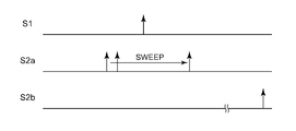
- the controller 26 sweeps the time difference ⁇ between the light emission control signal S1 and the exposure control signal S2, and monitors the change in the pixel value of one or a plurality of pixels (referred to as the pixel of interest) of the image sensor 24. For example, the controller 26 acquires the time difference ⁇ CAL when a relatively large pixel value is obtained.
- the time difference ⁇ CAL can be determined by the controller 26 or the processing device 28.
- L3a represents the departure time of the calibration light L3 from the calibration light source 30, and L3b represents the arrival time of the calibration light L3 to the image sensor 24.
- Tb There is a delay time Tb from the assertion of the light emission control signal S1 to the light emission timing (departure time) of the calibration light source 30.
- the pixel value Pa of the pixel of interest becomes zero when the arrival time L3b of the calibration light L3 deviates from the exposure period IS of the image sensor 24.
- the arrival time L3b of the calibration light L3 is included in the exposure period IS of the image sensor 24, the pixel value of the pixel of interest Pa increases.
- FIG. 10 is a block diagram of the sensing system 10.
- the sensing system 10 includes an arithmetic processing device 40 in addition to the gating camera 20 described above.
- the sensing system 10 is an object detection system that is mounted on a vehicle such as an automobile or a motorcycle and determines the type (also referred to as a category or class) of an object OBJ existing around the vehicle.
Landscapes
- Engineering & Computer Science (AREA)
- Physics & Mathematics (AREA)
- Multimedia (AREA)
- Mechanical Engineering (AREA)
- Computer Networks & Wireless Communication (AREA)
- General Physics & Mathematics (AREA)
- Radar, Positioning & Navigation (AREA)
- Remote Sensing (AREA)
- Electromagnetism (AREA)
- Studio Devices (AREA)
- Optical Radar Systems And Details Thereof (AREA)
Abstract
Description
以下、好適な実施形態について、図面を参照しながら説明する。各図面に示される同一または同等の構成要素、部材、処理には、同一の符号を付するものとし、適宜重複した説明は省略する。また、実施形態は、開示および発明を限定するものではなく例示であって、実施形態に記述されるすべての特徴やその組み合わせは、必ずしも開示および発明の本質的なものであるとは限らない。
図1は、実施形態に係るセンシングシステム10のブロック図である。このセンシングシステム10は、自動車やバイクなどの車両に搭載され、車両の周囲に存在する物体OBJを検出する。
TMINi=2×dMINi/c
である。cは光速である。
TMAXi=2×dMAXi/c
である。
図4は、実施例1に係るキャリブレーションを説明する図である。実施例1では、イメージセンサ24が生成する生画像IMG_RAWのうち1画素(注目画素という)のみに着目する。注目画素の位置は限定されないが、イメージセンサ24の中央であってもよい。
図6は、実施例2に係るキャリブレーションを説明する図である。実施例2では、同じ時間差τj(j=-2,-1,0,1,2)に対して、発光と露光を複数M回繰り返す。その結果、1個の時間差τjに関して、M個の画素値Pajが得られる。コントローラ26は、M個の画素値Pajを加算し、あるいは平均して得られる画素値Pjが増大するときの時間差τjを取得する。
キャリブレーション中に、キャリブレーション光L3に対して無視できない大きさの環境光がイメージセンサ24に入射すると、キャリブレーションの精度が低下する。
変形例1では、イメージセンサ24の近接する複数の画素が注目画素とされる。ゲーティングカメラ20は、複数の画素値から、代表値を生成し、代表値が増大するときの時間差τCALを取得してもよい。代表値は、複数の画素値の平均値、合計値、最大値などを用いることができる。
イメージセンサ24の露光タイミングが、面内ばらつきを有する場合があり得る。この場合、イメージセンサ24の離れた位置に、複数の注目画素を定め、注目画素ごとに、画素値が増大するときの時間差τCALを取得してもよい。これにより、イメージセンサ24のタイミング誤差の面内ばらつきをキャリブレーションできる。
図10は、センシングシステム10のブロック図である。センシングシステム10は、上述のゲーティングカメラ20に加えて演算処理装置40を備える。このセンシングシステム10は、自動車やバイクなどの車両に搭載され、車両の周囲に存在する物体OBJの種類(カテゴリ、あるいはクラスともいう)を判定する物体検出システムである。
Claims (13)
- 視野を奥行き方向について複数のレンジに区切り、前記複数のレンジに対応する複数のスライス画像を生成するゲーティングカメラであって、
発光制御信号と第1露光制御信号を生成可能なコントローラと、
通常撮影時に、前記発光制御信号に応じてプローブ光を照射する照明装置と、
前記第1露光制御信号に応じて露光するイメージセンサと、
キャリブレーション時に、前記発光制御信号に応じて前記イメージセンサにキャリブレーション光を照射するキャリブレーション用光源と、
を備え、
前記コントローラは、前記キャリブレーション時に、前記発光制御信号と前記第1露光制御信号の時間差をスイープし、各時間差における前記イメージセンサの画素値を監視することを特徴とするゲーティングカメラ。 - 前記コントローラは、前記キャリブレーション時に、前記イメージセンサが前記キャリブレーション光を検出できない期間に、第2露光制御信号を生成し、
前記コントローラは、前記第1露光制御信号に応じて得られる前記画素値を、前記第2露光制御信号に応じて得られる前記画素値により補正した値が、増大するときの前記時間差を取得することを特徴とする請求項1に記載のゲーティングカメラ。 - 前記第2露光制御信号は前記時間差を切りかえるたびに生成されることを特徴とする請求項2に記載のゲーティングカメラ。
- 前記第2露光制御信号は前記第1露光制御信号とセットで生成されることを特徴とする請求項2に記載のゲーティングカメラ。
- 前記イメージセンサはマルチタップイメージセンサであり、前記第1露光制御信号に応じて第1タップを利用して撮影し、前記第2露光制御信号に応じて第2タップを利用して撮影することを特徴とする請求項2から4のいずれかに記載のゲーティングカメラ。
- 前記照明装置はレーザダイオードを含み、
前記キャリブレーション用光源は発光ダイオードを含むことを特徴とする請求項1から5のいずれかに記載のゲーティングカメラ。 - 前記照明装置と前記キャリブレーション用光源は、駆動回路が共有されることを特徴とする請求項1から6のいずれかに記載のゲーティングカメラ。
- 前記コントローラは、前記イメージセンサの複数の画素値を監視し、画素値ごとに、前記画素値が増大するときの時間差を取得することを特徴とする請求項1から7のいずれかに記載のゲーティングカメラ。
- 前記コントローラは、前記イメージセンサの所定領域内の画素値を監視し、当該画素値が増大するときの前記時間差を取得することを特徴とする請求項1から7のいずれかに記載のゲーティングカメラ。
- 前記コントローラは、前記イメージセンサの複数の画素値を監視し、前記複数の画素値にもとづく代表値が増大するときの前記時間差を取得することを特徴とする請求項1から7のいずれかに記載のゲーティングカメラ。
- 車両に搭載されることを特徴とする請求項1から10のいずれかに記載のゲーティングカメラ。
- 請求項1から10のいずれかに記載のゲーティングカメラと、
前記ゲーティングカメラが撮影する前記複数のスライス画像を処理する演算処理装置と、
を備えることを特徴とする車両用センシングシステム。 - 請求項1から10のいずれかに記載のゲーティングカメラを備えることを特徴とする車両用灯具。
Priority Applications (2)
| Application Number | Priority Date | Filing Date | Title |
|---|---|---|---|
| JP2022572996A JP7746300B2 (ja) | 2020-12-28 | 2021-12-17 | ゲーティングカメラ、車両用センシングシステム、車両用灯具 |
| US18/269,883 US20240067094A1 (en) | 2020-12-28 | 2021-12-17 | Gating camera, vehicle sensing system, and vehicle lamp |
Applications Claiming Priority (2)
| Application Number | Priority Date | Filing Date | Title |
|---|---|---|---|
| JP2020-218975 | 2020-12-28 | ||
| JP2020218975 | 2020-12-28 |
Publications (1)
| Publication Number | Publication Date |
|---|---|
| WO2022145261A1 true WO2022145261A1 (ja) | 2022-07-07 |
Family
ID=82259238
Family Applications (1)
| Application Number | Title | Priority Date | Filing Date |
|---|---|---|---|
| PCT/JP2021/046824 Ceased WO2022145261A1 (ja) | 2020-12-28 | 2021-12-17 | ゲーティングカメラ、車両用センシングシステム、車両用灯具 |
Country Status (3)
| Country | Link |
|---|---|
| US (1) | US20240067094A1 (ja) |
| JP (1) | JP7746300B2 (ja) |
| WO (1) | WO2022145261A1 (ja) |
Families Citing this family (1)
| Publication number | Priority date | Publication date | Assignee | Title |
|---|---|---|---|---|
| EP4632430B1 (de) * | 2024-04-09 | 2026-02-18 | Sick Ag | Optischer sensor |
Citations (5)
| Publication number | Priority date | Publication date | Assignee | Title |
|---|---|---|---|---|
| JP2007198911A (ja) * | 2006-01-26 | 2007-08-09 | Matsushita Electric Works Ltd | 距離計測装置 |
| WO2013014761A1 (ja) * | 2011-07-27 | 2013-01-31 | ジックオプテックス株式会社 | 光波測距装置 |
| WO2016208214A1 (ja) * | 2015-06-24 | 2016-12-29 | 株式会社村田製作所 | 距離センサ |
| JP2019529931A (ja) * | 2016-09-30 | 2019-10-17 | マジック リープ, インコーポレイテッドMagic Leap,Inc. | 飛行時間深度測定のためのリアルタイム較正 |
| WO2020184447A1 (ja) * | 2019-03-11 | 2020-09-17 | 株式会社小糸製作所 | ゲーティングカメラ、自動車、車両用灯具、物体識別システム、演算処理装置、物体識別方法、画像表示システム、検査方法、撮像装置、画像処理装置 |
-
2021
- 2021-12-17 JP JP2022572996A patent/JP7746300B2/ja active Active
- 2021-12-17 US US18/269,883 patent/US20240067094A1/en active Pending
- 2021-12-17 WO PCT/JP2021/046824 patent/WO2022145261A1/ja not_active Ceased
Patent Citations (5)
| Publication number | Priority date | Publication date | Assignee | Title |
|---|---|---|---|---|
| JP2007198911A (ja) * | 2006-01-26 | 2007-08-09 | Matsushita Electric Works Ltd | 距離計測装置 |
| WO2013014761A1 (ja) * | 2011-07-27 | 2013-01-31 | ジックオプテックス株式会社 | 光波測距装置 |
| WO2016208214A1 (ja) * | 2015-06-24 | 2016-12-29 | 株式会社村田製作所 | 距離センサ |
| JP2019529931A (ja) * | 2016-09-30 | 2019-10-17 | マジック リープ, インコーポレイテッドMagic Leap,Inc. | 飛行時間深度測定のためのリアルタイム較正 |
| WO2020184447A1 (ja) * | 2019-03-11 | 2020-09-17 | 株式会社小糸製作所 | ゲーティングカメラ、自動車、車両用灯具、物体識別システム、演算処理装置、物体識別方法、画像表示システム、検査方法、撮像装置、画像処理装置 |
Also Published As
| Publication number | Publication date |
|---|---|
| JPWO2022145261A1 (ja) | 2022-07-07 |
| JP7746300B2 (ja) | 2025-09-30 |
| US20240067094A1 (en) | 2024-02-29 |
Similar Documents
| Publication | Publication Date | Title |
|---|---|---|
| JP7594539B2 (ja) | ゲーティングカメラ、自動車、車両用灯具、画像処理装置、画像処理方法 | |
| CN113557172B (zh) | 选通照相机、汽车、车辆用灯具、物体识别系统、运算处理装置、物体识别方法、图像显示系统、检查方法、摄像装置、图像处理装置 | |
| US11073379B2 (en) | 3-D environment sensing by means of projector and camera modules | |
| JP7695230B2 (ja) | ゲーティングカメラ、車両用センシングシステム、車両用灯具 | |
| JP7653436B2 (ja) | ゲーティングカメラ、車両用センシングシステム、車両用灯具 | |
| US11303817B2 (en) | Active sensor, object identification system, vehicle and vehicle lamp | |
| JP7746300B2 (ja) | ゲーティングカメラ、車両用センシングシステム、車両用灯具 | |
| WO2021015208A1 (ja) | アクティブセンサ、ゲーティングカメラ、自動車、車両用灯具 | |
| WO2021193645A1 (ja) | ゲーティングカメラ、センシングシステム、車両用灯具 | |
| WO2020218283A1 (ja) | ToFカメラ、車両用灯具、自動車 | |
| JP7474759B2 (ja) | 車両用灯具 | |
| US20250328994A1 (en) | ToF IMAGING CAMERA, VEHICLE SENSING SYSTEM, AND VEHICLE LAMP | |
| US12555194B2 (en) | Gating camera, sensing system for vehicle, vehicle lamp | |
| JP7804684B2 (ja) | ゲーティングカメラ、車両用センシングシステム、車両用灯具 | |
| JP7656584B2 (ja) | センサ、自動車および周囲環境のセンシング方法 | |
| US12559022B2 (en) | Gating camera, vehicle sensing system, and vehicle lamp | |
| US20250004137A1 (en) | Active sensor, object identification system, vehicle lamp | |
| WO2023189599A1 (ja) | 距離画像センサ、および車両用灯具 | |
| WO2023085403A1 (ja) | センシングシステム | |
| CN118215854A (zh) | 感测系统及汽车 |
Legal Events
| Date | Code | Title | Description |
|---|---|---|---|
| 121 | Ep: the epo has been informed by wipo that ep was designated in this application |
Ref document number: 21915121 Country of ref document: EP Kind code of ref document: A1 |
|
| ENP | Entry into the national phase |
Ref document number: 2022572996 Country of ref document: JP Kind code of ref document: A |
|
| WWE | Wipo information: entry into national phase |
Ref document number: 18269883 Country of ref document: US |
|
| NENP | Non-entry into the national phase |
Ref country code: DE |
|
| 122 | Ep: pct application non-entry in european phase |
Ref document number: 21915121 Country of ref document: EP Kind code of ref document: A1 |