WO2022145159A1 - ヘッド交換式歯ブラシ - Google Patents
ヘッド交換式歯ブラシ Download PDFInfo
- Publication number
- WO2022145159A1 WO2022145159A1 PCT/JP2021/043815 JP2021043815W WO2022145159A1 WO 2022145159 A1 WO2022145159 A1 WO 2022145159A1 JP 2021043815 W JP2021043815 W JP 2021043815W WO 2022145159 A1 WO2022145159 A1 WO 2022145159A1
- Authority
- WO
- WIPO (PCT)
- Prior art keywords
- axis direction
- leaf spring
- head
- shaft portion
- detachment assisting
- Prior art date
- Legal status (The legal status is an assumption and is not a legal conclusion. Google has not performed a legal analysis and makes no representation as to the accuracy of the status listed.)
- Ceased
Links
Images





Classifications
-
- A—HUMAN NECESSITIES
- A46—BRUSHWARE
- A46B—BRUSHES
- A46B5/00—Brush bodies; Handles integral with brushware
-
- A—HUMAN NECESSITIES
- A46—BRUSHWARE
- A46B—BRUSHES
- A46B7/00—Bristle carriers arranged in the brush body
- A46B7/04—Bristle carriers arranged in the brush body interchangeably removable bristle carriers
-
- A—HUMAN NECESSITIES
- A61—MEDICAL OR VETERINARY SCIENCE; HYGIENE
- A61C—DENTISTRY; APPARATUS OR METHODS FOR ORAL OR DENTAL HYGIENE
- A61C17/00—Devices for cleaning, polishing, rinsing or drying teeth, teeth cavities or prostheses; Saliva removers; Dental appliances for receiving spittle
- A61C17/16—Power-driven cleaning or polishing devices
- A61C17/22—Power-driven cleaning or polishing devices with brushes, cushions, cups, or the like
Definitions
- the present invention relates to an interchangeable head toothbrush.
- This application claims priority based on Japanese Patent Application No. 2020-218456 filed in Japan on December 28, 2020, the contents of which are incorporated herein by reference.
- a toothbrush has a head part having a brush part and a handle part connected to each other, so when replacing the toothbrush due to opening of hair, it is necessary to replace the entire toothbrush.
- the head replaceable toothbrush in which the head portion can be attached and detached from the handle portion, only the replacement head portion may be replaced when the toothbrush is replaced. Therefore, the amount of resin used in the handle is reduced, which is environmentally friendly.
- an electric toothbrush known as a kind of replaceable head toothbrush has a shaft portion extending from the main body portion inserted and fitted inside the replacement head portion at a fitting portion between the replacement head portion having a brush portion and the main body portion. It is fixed by (for example, Patent Document 1).
- the shaft portion is fixed, the shaft is sandwiched and fitted by two parts, a leaf spring on the front side and a support plate on the back side inside the replacement head portion.
- the main body contains a battery, a step is generated between the main body having different diameters and the neck portion in the replacement head portion. Therefore, in the replacement head portion, an outline connecting the surfaces so as to fill this step exists on the radial outer side of the leaf spring / support plate.
- the thinner the neck part the better the operability and the easier it is to brush the teeth. Therefore, it is being considered to make the neck part thinner and improve the operability by removing the outline.
- the leaf spring and the support plate are exposed at the fitting part excluding the outline.
- the leaf spring or the support plate is pressed in the fitting direction, which makes it difficult to pull out.
- the neck portion is gripped, a part of the neck portion enters the oral cavity, which is unsanitary. Therefore, when the outline is removed in consideration of operability, there arises a problem of pulling out of the replacement head portion.
- the present invention has been made in consideration of the above points, and an object of the present invention is to provide a head replaceable toothbrush capable of improving operability and pulling out of a replaceable head portion.
- a head exchangeable toothbrush in which a main body portion and an exchangeable head portion having a brush portion and arranged on the tip side in the long axis direction of the main body portion can be attached and detached, the main body portion.
- the portion has a grip portion and a shaft portion extending from the grip portion to the tip end side in the long axis direction
- the replacement head portion includes a head main body portion having the brush portion and the head main body portion to the head main body portion.
- a leaf spring portion that extends to the rear end side in the major axis direction and is fitted to the shaft portion by an elastic force on one side toward the shaft portion in a radial direction orthogonal to the major axis direction, and is connected to the leaf spring portion.
- a head-replaceable toothbrush having a detachment assisting portion that deforms the leaf spring portion to the other side in the radial direction when an external force is applied.
- the leaf spring portions are provided in pairs on both sides in the radial direction with the shaft portion interposed therebetween, and the detachment assisting portion is the leaf spring portion.
- the detachment assisting portion is the leaf spring portion.
- Each of the pair of detachment assisting portions is formed in a convex shape that bulges outward in the minor axis direction through a gap with respect to the shaft portion in the fitted state.
- the leaf spring portion is connected to the leaf spring portion via a hinge portion that is relatively movable around an axis segment extending in the long axis direction, and the ends of the leaf spring portion in the fitted state are connected to each other in the short axis direction.
- the line segment connecting the two is L
- the length of the line segment L is D1
- the maximum distance between the outer surface of the detachment assisting portion and the line segment L is D2
- D1 ⁇ 2 ⁇ D2 is satisfied. It is characterized by.
- a plurality of detachment assisting portions are provided at intervals in the circumferential direction centering on the shaft portion, and a plurality of flat plate portions having a flat surface on the outer surface. It is characterized by having a curved portion connected to the flat plate in the circumferential direction and having a curved surface on an outer surface, and one of the plurality of flat plate portions is located outside in the minor axis direction.
- a toothbrush having a curved surface on an outer surface and connecting one of the flat plate portions and the end portion of the leaf spring portion in the minor axis direction in the circumferential direction. It is characterized by having two curved portions.
- the thickness of the curved portion and the thickness of the second curved portion are smaller than the thickness of the flat plate portion.
- the shaft portion is in contact with one of the pair of leaf spring portions in a fitted state in which the leaf spring portion and the shaft portion are fitted. It has a contact portion and a recess located on the rear end side of the contact portion in the major axis direction and opening toward one of the leaf spring portions in the fitted state, and one of the leaf spring portions.
- the protrusion amount of the protrusion is 1 ⁇ 2 or less with respect to the maximum depth of the recess.
- the recess is arranged on the bottom side of the recess so as to straddle the grip portion and the shaft portion, or is arranged in the grip portion and has the diameter. It is characterized in that an inclined portion that gradually inclines toward the tip end side in the long axis direction is provided toward one side in the direction.
- the shaft portion is a side surface facing the recess toward the back surface side gradually from the rear end side to the rear end side in the long axis direction of the contact portion.
- the protrusion is located on the rear end side of the contact portion in the fitted state, and is characterized in that it engages with the side surface on the tip side in the long axis direction.
- the present invention can provide a head replaceable toothbrush that can improve operability and pullability of the replaceable head portion.
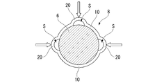
- FIG. 2 is a sectional view taken along line II-II in FIG. It is a partially enlarged view around the intersection of the detachment assisting portion 20 and the leaf spring portion 10. It is sectional drawing of the detachable part 8 which released the mating state. It is sectional drawing of the detachable part 8 in the plane including the central axis.
- FIG. 5 is a sectional view taken along line III-III in FIG. 5, which is a view seen from the grip portion 2 side. It is sectional drawing of the detachable part 8 which shows the operation of releasing the fitting state. It is a front view which shows the modification of the 2nd Embodiment. It is sectional drawing which shows the modification of the exchangeable toothbrush which concerns on 1st Embodiment. It is sectional drawing which shows the modification of the exchangeable toothbrush which concerns on 1st Embodiment.
- FIGS. 1 to 8 embodiments of the replaceable head toothbrush of the present invention will be described with reference to FIGS. 1 to 8. It should be noted that the following embodiments show one aspect of the present invention, do not limit the present invention, and can be arbitrarily changed within the scope of the technical idea of the present invention. Further, in the following drawings, in order to make each configuration easy to understand, the scale and number of each structure are different from the actual structure.
- the head exchangeable toothbrush 1 shown in FIG. 1 has a grip portion 2, a neck portion 3 provided on the tip side of the grip portion 2 in the long axis direction, and a tip side of the neck portion 3.
- the head portion 4 provided in the above is provided.
- the head-replaceable toothbrush 1 cleans the oral cavity with a plurality of hair bundles of the brush portion 5 planted on the flocked surface 4a of the head portion 4.
- the replaceable head portion 1B including the neck portion 3, the head portion 4 and the brush portion 5 can be attached to and detached from the main body portion 1A including the grip portion 2 in the detachable portion 8. It has a replaceable structure that can be attached to.
- the side of the head portion 4 provided with the flocked surface 4a is the front side of the replacement head portion 1B, and the side opposite to the side of the head portion 4 provided with the flocked surface 4a is the back surface of the replacement head portion 1B. Be on the side.
- the direction orthogonal to the flocked surface 4a and orthogonal to the central axis of the main body 1A extending in the long axis direction is the radial direction (in the present embodiment, the "thickness direction" is distinguished from the short axis direction described later. It may be referred to as).
- the side on which the head portion 4 (replacement head portion 1B) is arranged is the front end side
- the side on which the grip portion 2 (main body portion 1A) is arranged is the rear end side. do.
- the direction parallel to the flocked surface 4a and orthogonal to the long axis direction will be described as the short axis direction (in the present embodiment, it may be referred to as the "width direction" to distinguish it from the above-mentioned radial direction).
- the head replaceable toothbrush 1 is not limited to the manual toothbrush, but the brush portion 5 is planted on the flocked surface 4a of the head portion 4 while the main body portion 1A has a power source and is electrically driven to generate vibration. It may be an electric toothbrush that cleans the inside of the oral cavity.
- the main body portion 1A has a grip portion 2 whose end portion on the distal end side serves as a boundary with the detachable portion 8, and a shaft portion 6 extending from the end surface on the distal end side of the grip portion 2 toward the distal end side in the long axis direction.
- the shaft portion 6 is a columnar shape coaxial with the central axis of the main body portion 1A.
- the tip of the shaft portion 6 is located in the region of the neck portion 3 in the replacement head portion 1B beyond the attachment / detachment portion 8.
- the diameter of the shaft portion 6 is smaller than the diameter of the grip portion 2.
- the diameter of the shaft portion 6 is preferably 2 mm or more and 5 mm or less, and more preferably 2 mm or more and 4 mm or less.
- the diameter of the grip portion 2 is preferably 14 mm or more and 20 mm or less, and more preferably 14 mm or more and 16 mm or less. Since the diameter of the shaft portion 6 is smaller than the diameter of the grip portion 2, the fitting portion with the shaft portion 6 becomes thinner in the exchange head portion 1B, and as a result, the neck portion 3 also becomes thinner, as a head replaceable toothbrush. Operability is improved.
- the replacement head portion 1B has a head main body portion 7 and a detachable portion 8.
- the head body portion 7 includes the neck portion 3, the head portion 4, and the brush portion 5.
- the attachment / detachment portion 8 has a leaf spring portion 10 and a detachment assisting portion 20.
- the leaf spring portion 10 and the detachment assisting portion 20 extend from the head main body portion 7 toward the rear end side in the long axis direction.
- FIG. 2 is a sectional view taken along line II-II in FIG.
- the vertical direction of the paper surface is the radial direction (thickness direction)
- the upper side of the paper surface is the front side of the head replaceable toothbrush 1
- the lower side of the paper surface is the back side.
- the surface left-right direction in FIG. 2 is the short axis direction (width direction).
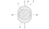
- FIG. 2 shows a fitted state in which the leaf spring portion 10 and the shaft portion 6 are fitted to each other.
- the leaf spring portions 10 are provided in pairs on both sides in the radial direction (thickness direction) with the shaft portion 6 interposed therebetween.
- the leaf spring portion 10 is arranged on the front side and the back side of the shaft portion 6, respectively.
- the cross-sectional shape of the leaf spring portion 10 in the fitted state is a semicircular shape coaxial with the shaft portion 6.
- the inner peripheral surface of the leaf spring portion 10 is in surface contact with the outer peripheral surface of the shaft portion 6 in the fitted state.
- the leaf spring portion 10 fits with the shaft portion 6 by an elastic force on one side toward the shaft portion 6 in the radial direction (thickness direction), and sandwiches the shaft portion 6 in the radial direction.
- the elastic force on one side of the leaf spring portion 10 is the elastic restoring force when the leaf spring portion 10 is elastically deformed by fitting with the shaft portion 6.
- the leaf spring portion 10 suppresses the pulling out of the shaft portion 6 by the frictional force generated by the elastic force toward the shaft portion 6.
- the number of leaf spring portions 10 is preferably a plurality, more preferably two.
- the thickness of the leaf spring portion 10 is preferably 0.5 mm or more and 2.0 mm or less, and more preferably 0.8 mm or more and 1.2 mm or less. If the thickness of the leaf spring portion 10 is less than 0.5 mm, sufficient fitting strength cannot be obtained, and if the thickness of the leaf spring portion 10 exceeds 2.0 mm, the pullability of the replacement head portion 1B is remarkable. descend. By setting the thickness of the leaf spring portion 10 to 0.5 mm or more and 2.0 mm or less, it is possible to secure an appropriate fitting strength and pull-out strength of the replacement head portion 1B.
- the detachment assisting portion 20 is connected to the leaf spring portion 10 and deforms the leaf spring portion to the other side in the radial direction (thickness direction) when an external force is applied.
- the detachment assisting portions 20 are provided on both sides in the short axis direction (width direction) sandwiching the shaft portion 6.
- the detachment assisting portions 20 are provided in pairs by connecting the ends of the leaf spring portions 10 on the same side in the short axis direction (width direction).
- Each of the pair of detachment assisting portions 20 is formed in a convex shape that swells outward in the short axis direction (width direction) through the gap S with respect to the shaft portion 6 in the fitted state.
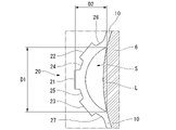
- FIG. 3 is a partially enlarged view of the periphery of the intersection between the detachment assisting portion 20 and the leaf spring portion 10. Since the configuration of the pair of detachment assisting portions 20 is the same, one of the pair of detachment assisting portions 20 will be described here, and the other will be omitted.
- the detachment assisting portion 20 includes a plurality of flat plate portions 21, 22, 23, a plurality of first curved portions (curved portions) 24, 25, and a plurality of second curved portions 26, 27. have.
- the flat plate portions 21, 22 and 23 have a flat surface on the outer surface, and are arranged so as to be spaced apart from each other in the circumferential direction centered on the shaft portion 6.
- the center position of the flat plate portion 21 in the circumferential direction is on a straight line extending in the minor axis direction from the central axis of the main body portion 1A.
- the first curved portions 24, 25 have a curved surface that is convex toward the outside on the outer surface.
- the first curved portion 24 connects the flat plate portions 21 and 22 adjacent to each other in the circumferential direction.
- the first curved portion 25 connects the flat plate portions 21 and 23 adjacent to each other in the circumferential direction.
- the second curved portions 26, 27 have a curved surface that is concave toward the outside on the outer surface.
- the second curved portion 26 connects the flat plate portion 22 and the end portion of the leaf spring portion 10 in the minor axis direction in the circumferential direction.
- the second curved portion 27 connects the flat plate portion 23 and the end portion of the leaf spring portion 10 in the minor axis direction in the circumferential direction.
- the detachment assisting portion 20 and the leaf spring portion 10 are connected in the circumferential direction by the second curved portions 26 and 27 having curved surfaces that are concave toward the outside on the outer surface, the detachment assisting portion 20 is hinged. Functions as a department. Since the detachment assisting portion 20 functions as a hinge portion, the detaching assisting portion 20 can move relative to the leaf spring portion 10 around an axis extending in the long axis direction.
- the thickness of the first curved portions 24 and 25 and the thickness of the second curved portions 26 and 27 are smaller than the thickness of the flat plate portions 21, 22 and 23.
- the detachment assisting portion 20 as the hinge portion includes the flat plate portions 21, 22, and 23 having a flat surface on the outer surface, it becomes easy for the user to apply stress when pressing, so that the pullability of the replacement head portion 1B is improved. do. Further, since the thickness of the first curved portions 24 and 25 and the thickness of the second curved portions 26 and 27 are smaller than the thickness of the flat plate portions 21, 22 and 23, the first of the flat plate portions 21, 22 and 23. Since the curved portions 24 and 25 and the second curved portions 26 and 27 are preferentially deformed, the user can easily press the detachment assisting portion 20 which is a hinge portion, and the pullability of the replacement head portion 1B is improved. Can be done.
- the second curved portions 26 and 27 connecting the leaf spring portion 10 and the detachment assisting portion 20 have a curved shape, the stress when the detachment assisting portion 20 is pressed is transmitted to the leaf spring portion 10. Since it becomes easy, the fitting between the leaf spring portion 10 and the shaft portion 6 can be released with a small amount of stress.
- the maximum thickness of the detachment assisting portion 20, that is, the thicknesses of the flat plate portions 21, 22, and 23 are preferably 0.3 mm or more and 1.2 mm or less, and more preferably 0.3 mm or more and 0.7 mm or less.
- the maximum thickness of the detachment assisting portion 20 is less than 0.3 mm, it is difficult to return to the original shape even if the detachment assisting portion 20 is pressed and deformed and then released.
- the maximum thickness of the detachment assisting portion 20 exceeds 1.2 mm, a large stress is required when deforming the detachment assisting portion 20, so that the pullability of the replacement head portion 1B is significantly reduced. It is preferable that the detachment assisting portion 20 and the leaf spring portion 10 are the same molded body because they exhibit elasticity.
- Is L the length of the line segment L is D1
- the maximum distance between the outer surface of the detachment assisting portion 20 and the line segment L is D2
- the length D1 of the line segment L is preferably 0.03 mm or more and 0.24 mm, more preferably 0.12 mm or more and 0.21 mm or less, and further preferably 0.15 mm or more and 0.21 mm or less.
- the maximum distance D2 is preferably 0.05 mm or more and 0.12 mm or less, more preferably 0.06 mm or more and 0.10 mm or less, and further preferably 0.07 mm or more and 0.10 mm or less. Since each of the detachment assisting portions 20 is formed in a convex shape that swells outward in the minor axis direction through the gap S with respect to the shaft portion 6 in the fitted state, the user shortens the detachment assisting portion 20. It becomes easier to push toward the shaft portion 6 side in the axial direction. Further, by satisfying the relationship of D1 ⁇ 2 ⁇ D2, as shown by the arrow in FIG.
- the detachment assisting portion 20 is pressed toward the shaft portion 6 in the short axis direction, as shown in FIG.
- the detachment assisting portion 20 is elastically deformed into a flat plate extending in the radial direction, and the pair of leaf spring portions 10 are expanded and moved radially outward as shown by arrows.
- the detachment assisting portion 20 is composed of one or a plurality.
- the detachment assisting portion 20 illustrates two embodiments, but one to four are preferable.
- the length of the detachment assisting portion 20 in the major axis direction is preferably 0.4 mm or more and 1.5 mm or less, which is equivalent to the length of the leaf spring portion 10.
- the length of the detachment assisting portion 20 in the major axis direction is less than 0.4 mm, it becomes difficult to press the detaching assisting portion 20. If the length of the detachment assisting portion 20 in the major axis direction exceeds 1.5 mm, the neck portion 3 or the grip portion 2 may become short and the operability may deteriorate.
- the length of the detachment assisting portion 20 in the major axis direction By setting the length of the detachment assisting portion 20 in the major axis direction to 0.4 mm or more and 1.5 mm or less, operability and ease of pressing the detachment assisting portion 20 can be ensured.
- saliva during tooth brushing or oral preparation may invade the void S from the head part through the neck part, or water may infiltrate into the gap S when washed away with water including the head part after tooth brushing. be.
- the above-mentioned water or the like remaining in the void S may generate bacteria if left unattended, which may adversely affect hygiene. This is a problem peculiar to toothbrushes (especially replacement toothbrushes).
- the relationship of "length in the major axis direction of the detachment assisting portion 20" / "maximum distance D2 of the detachment assisting portion 20" ⁇ 15 makes it easy for the above water or the like to be discharged from the void S.
- the length of the detachment assisting portion 20 should be short regardless of the cross-sectional area of the void S in order to exhibit water dischargeability.
- the "length in the major axis direction of the detachment assisting portion 20" / "maximum distance D2 of the detachment assisting portion 20" is preferably 15 or less, more preferably 10 or less, still more preferably 5 or less.
- the length of the leaf spring portion 10 in the major axis direction is preferably 0.4 mm or more and 1.5 mm or less.
- the stress required for the leaf spring portion 10 to move increases according to the principle of the lever, so that the pullability is lowered.
- the length of the leaf spring portion 10 in the major axis direction exceeds 1.5 mm, the stress required for the leaf spring portion 10 to operate is reduced by the principle of the lever, so that the replacement head portion 1B can be easily pulled out and brushing. Time stability is reduced.
- the pullability of the replaceable head portion 1B can be improved while improving the operability.
- FIGS. 5 to 8 the same components as the components of the first embodiment shown in FIGS. 1 to 4 are designated by the same reference numerals, and the description thereof will be omitted.
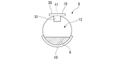
- FIG. 5 is a cross-sectional view of the attachment / detachment portion 8 on a plane including the central axis.
- FIG. 6 is a sectional view taken along line III-III in FIG. 5, which is a view seen from the grip portion 2 side.
- the shaft portion 6 is located at the contact portion 11 in contact with one of the leaf spring portions 10 located on the front side and the rear end side of the contact portion 11 in the long axis direction. It has a recess 12 that opens toward one leaf spring portion 10 in the fitted state.
- the contact portion 11 is an outer peripheral surface of the shaft portion 6 facing the leaf spring portion 10.
- the shaft portion 6 has a portion having a shape (trapezoidal shape) protruding in the leaf spring direction, the boundary between the shaft portion 6 and the leaf spring 10 does not abut.
- the shaft portion 6 has an inclined surface (side surface) 11a gradually toward the back surface side from the end portion of the contact portion 11 on the rear end side in the major axis direction toward the rear end side, and the tip end of the contact portion 11 in the major axis direction. It has an inclined surface 11b gradually toward the back surface side from the end on the side toward the tip side.
- the inclined surface 11a faces the recess 12.
- One leaf spring portion 10 located on the front side is located on the rear end side in the long axis direction of the contact portion 11 in the fitted state, and the first protrusion (1st protrusion) protruding from the back surface side of the leaf spring portion 10 into the recess 12. It has a protrusion) 31 and a second protrusion 32 that is located at the rear end side in the long axis direction and protrudes from the back surface side of the leaf spring portion 10 into the recess 12.
- the region on the rear end side in the long axis direction with respect to the first protrusion 31 is the detachment assisting portion 30.
- the first protrusion 31 has an inclined surface 31a on the tip end side in the long axis direction.
- the inclination angle of the inclined surface 31a is substantially the same as the inclination angle of the inclined surface 11a.
- the first protrusion 31 is located on the rear end side in the long axis direction with respect to the contact portion 11 in the fitted state, and engages with the inclined surface 11a on the inclined surface 31a on the tip side in the long axis direction.
- the amount of protrusion of the first protrusion 31 toward the back surface is preferably 1/2 or less with respect to the maximum depth of the recess 12.
- the rear end side end portion of the detachment assisting portion 30 is used as a power point, and one leaf spring portion 10 is applied.
- the contact point of the contact portion 11 is used as a fulcrum, and the point where the first protrusion 31 and the inclined surface 11a are engaged is set as the point of action. Since stress is applied so as to separate, the fitting to the shaft portion 6 becomes weak.
- the maximum depth of the recess 12 (the maximum depth when starting from the maximum position in the radial direction (thickness direction) of the contact portion 11 in FIG. 5) is 0.3 mm or more and 1.2 mm or less. It is preferable, and it is more preferable that it is 0.5 mm or more and 1.0 mm or less. By setting the maximum depth of the recess 12 to 0.3 mm or more and 1.2 mm or less, a sufficient pushing amount of the detachment assisting portion can be secured, so that the pullability is improved.
- the maximum distance between the shaft portion 6 and the detachment assisting portion 30 via the recess 12 is preferably 0.5 mm or more and 1.5 mm or less, and preferably 0.8 mm or more and 1.2 mm or less. More preferred. If the distance between the shaft portion 6 and the detachment assisting portion 30 is less than 0.5 mm, a sufficient amount of deformation of the detachment assisting portion 30 cannot be obtained. When the distance between the shaft portion 6 and the detachment assisting portion 30 exceeds 1.5 mm, the neck portion 3 becomes thick and the brush operability deteriorates.
- the maximum distance in the longitudinal direction between the first protrusion 31 and the detachment assisting portion 30 is preferably 0.3 mm or more and 1.2 mm or less, and more preferably 0.5 mm or more and 1.0 mm or less.
- saliva during tooth brushing and oral preparations may invade "between the shaft portion 6 and the detachment assisting portion 30 via the recess 12" from the head portion through the neck portion, or the head portion after tooth brushing.
- water may infiltrate "between the shaft portion 6 and the detachment assisting portion 30 via the recess 12".
- the above-mentioned water and the like remaining during the period may generate bacteria if left unattended, which may adversely affect hygiene. This is a problem peculiar to toothbrushes (especially replacement toothbrushes).
- the thickness of the detachment assisting portion 30 is preferably 0.3 mm or more and 1.2 mm or less, and more preferably 0.3 mm or more and 0.7 mm or less. If the thickness of the detachment assisting portion 30 is less than 0.3 mm, it becomes difficult to return to the original shape after the detachment assisting portion 30 is deformed. When the thickness of the detachment assisting portion 30 exceeds 1.2 mm, a large stress is required for the deformation of the detachment assisting portion 30, so that the pullability of the replacement head portion 1B is significantly reduced. By setting the thickness of the detachment assisting portion 30 to 0.3 mm or more and 1.2 mm or less, the detachment assisting portion 30 is easily deformed even with a small stress, and the pullability of the replacement head portion 1B is improved.
- the inclination angle of the inclined portion 13 with respect to the major axis direction is preferably 45 ° or more and 80 ° or less.
- the inclination angle of the inclined portion 13 with respect to the major axis direction is less than 45 °, the component force parallel to the inclination becomes small, so that a large stress is required when pressing the detachment assisting portion 30.
- the inclination angle of the inclined portion 13 with respect to the long axis direction exceeds 80 °, the moving distance in the long axis direction becomes small, which does not contribute to the improvement of pullability.
- the inclination angle of the inclined portion 13 with respect to the major axis direction is set to 45 ° or more and 80 ° or less, so that the stress when the detachment assisting portion 30 is pressed is in the major axis direction. It is easily converted into stress.
- the tip of the detachment assisting portion 30 on the rear end side is pressed toward the concave portion 12 on the back side as shown by an arrow in FIG. 7 in the fitted state.
- stress is applied so that the first protrusion 31 is separated from the inclined surface 11a (shaft portion 6) toward the front side by the above-mentioned principle of the lever, and the first protrusion 31 moves to the front side.
- the engagement between the first protrusion 31 and the inclined surface 11a (shaft portion 6) is released.
- the mating state is released, and the replacement head portion 1B can be pulled out from the main body portion 1A.
- the leaf spring portion 10 is provided with the first protrusion 31 that engages with the shaft portion 6 in the long axis direction, so that the fitting is high. It is possible to secure the combined strength.
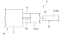
- FIG. 8 is a front view showing a modified example of the second embodiment.
- the inclined portion 13 has a groove portion 13a.
- the groove portion 13a opens to the front side.
- the groove portion 13a extends in the major axis direction.
- the width of the groove portion 13a in the minor axis direction is formed wider than the width of the second protrusion 32 provided in the detachment assisting portion 30.
- Other configurations are the same as those in the second embodiment.
- the second protrusion 32 is inserted into the groove portion 13a when the detachment assisting portion 30 is pressed toward the concave portion 12 toward the back surface side. As a result, the second protrusion 32 moves while being guided by the groove portion 13a, so that the shake in the short axis direction can be reduced, and the stability when the detachment assisting portion 30 is pressed is improved.
- the detachment assisting portions 20 are arranged on both sides in the short axis direction with the shaft portion 6 interposed therebetween is exemplified, but the configuration is not limited to this.
- the detachment assisting portions 20 may be provided on one side and the front side in the short axis direction, respectively.
- the number of the detachment assisting portions 20 is not limited to two.
- a configuration in which three are provided or a configuration in which only one is provided may be provided.
- the present invention can be applied to a head replaceable toothbrush.
Landscapes
- Health & Medical Sciences (AREA)
- Dentistry (AREA)
- Epidemiology (AREA)
- Life Sciences & Earth Sciences (AREA)
- Animal Behavior & Ethology (AREA)
- General Health & Medical Sciences (AREA)
- Public Health (AREA)
- Veterinary Medicine (AREA)
- Brushes (AREA)
Abstract
本発明は、操作性と交換ヘッドの引き抜き性を向上できるヘッド交換式歯ブラシを提供することを目的とする。本体部と、ブラシ部を有し本体部の長軸方向の先端側に配置された交換ヘッド部とが着脱可能なヘッド交換式歯ブラシにおいて、本体部は、把持部と、把持部から長軸方向の先端側に延びる軸部と、を有する。交換ヘッド部は、ブラシ部を有するヘッド本体部と、ヘッド本体部から長軸方向の後端側に延び、長軸方向と直交する径方向で軸部に向かう一方側の弾性力で軸部と嵌合する板バネ部と、板バネ部に繋がり、外力を付与されたときに板バネ部を径方向の他方側に変形させる脱離補助部と、を有する。
Description
本発明は、ヘッド交換式歯ブラシに関する。
本願は、2020年12月28日に、日本に出願された特願2020-218456号に基づき優先権を主張し、その内容をここに援用する。
本願は、2020年12月28日に、日本に出願された特願2020-218456号に基づき優先権を主張し、その内容をここに援用する。
一般的に歯ブラシは、ブラシ部を有するヘッド部とハンドル部が結合されているため、毛が開くなどして歯ブラシを交換する際には、歯ブラシ全体を交換する必要がある。それに対し、ハンドル部からヘッド部が着脱可能なヘッド交換式歯ブラシは、歯ブラシを交換する際に交換ヘッド部のみの交換で良い。そのためハンドル部の樹脂の使用量が減り、環境にも優しい。
従来、ヘッド交換式歯ブラシの一種として知られている電動歯ブラシは、ブラシ部を有する交換ヘッド部と本体部の嵌合部分で本体部から伸びる軸部が交換ヘッド部の内部に挿入・嵌合されることで固定される(例えば、特許文献1)。軸部が固定される際、交換ヘッド部の内部では正面側に板バネ、背面側に支持板の2つの部品で軸が挟まれて嵌合する。電動歯ブラシの場合には、本体部に電池が含まれるため、直径の異なる本体部と交換ヘッド部におけるネック部分の間に段差が生じる。そのため、交換ヘッド部には、この段差を埋めるように表面を繋ぐアウトラインが板バネ・支持板の径方向外側に存在する。
一方、歯ブラシにおいては、ネック部が細いほど操作性に優れ歯みがきがしやすくなるため、アウトラインを除くことでネック部を細くし操作性を向上させることが検討されている。
しかしながら、ヘッド交換式歯ブラシにおいては、アウトラインを除いた嵌合部は板バネと支持板が露出した状態となる。この場合、本体部から交換ヘッド部を引き抜く際、嵌合部を把持すると、板バネ又は支持板を嵌合方向に押さえてしまうため引き抜くことが困難となる。また、ネック部を把持すると、ネック部の一部は口腔内に入るため不衛生である。従って、操作性を考慮してアウトラインを除いた場合には、交換ヘッド部の引き抜き性の課題が生じる。
本発明は、以上のような点を考慮してなされたもので、操作性と交換ヘッド部の引き抜き性を向上できるヘッド交換式歯ブラシを提供することを目的とする。
本発明の第1の態様に従えば、本体部と、ブラシ部を有し前記本体部の長軸方向の先端側に配置された交換ヘッド部とが着脱可能なヘッド交換式歯ブラシにおいて、前記本体部は、把持部と、前記把持部から前記長軸方向の先端側に延びる軸部と、を有し、前記交換ヘッド部は、前記ブラシ部を有するヘッド本体部と、前記ヘッド本体部から前記長軸方向の後端側に延び、前記長軸方向と直交する径方向で前記軸部に向かう一方側の弾性力で前記軸部と嵌合する板バネ部と、前記板バネ部に繋がり、外力を付与されたときに前記板バネ部を前記径方向の他方側に変形させる脱離補助部と、を有することを特徴とするヘッド交換式歯ブラシが提供される。
また、上記本発明の一態様に係るヘッド交換式歯ブラシにおいて、前記板バネ部は、前記軸部を挟んで前記径方向の両側に対で設けられ、前記脱離補助部は、前記板バネ部と前記軸部とが嵌合する嵌合状態で、前記軸部を挟んで前記径方向と前記長軸方向とに直交する短軸方向の両側に、それぞれが前記板バネ部の前記短軸方向の端部同士を繋いで対で設けられ、一対の前記脱離補助部のそれぞれは、前記嵌合状態の前記軸部に対して空隙を介して前記短軸方向の外側に膨らむ凸状に形成されるとともに、前記板バネ部に対して前記長軸方向に延びる軸線回りに相対移動可能とするヒンジ部を介して繋がり、前記嵌合状態の前記板バネ部の前記短軸方向の端部同士を結ぶ線分をLとし、線分Lの長さをD1とし、前記脱離補助部の外面と前記線分Lとの最大距離をD2とすると、D1≧2×D2の関係を満足することを特徴とする。
また、上記本発明の一態様に係るヘッド交換式歯ブラシにおいて、前記脱離補助部は、前記軸部を中心とする周方向に間隔をあけて複数設けられ、外面に平面を有する複数の平板部と、前記平板に前記周方向に接続され、外面に湾曲面を有する湾曲部とを有し、前記複数の平板部の一つは、前記短軸方向の外側に位置することを特徴とする。
また、上記本発明の一態様に係るヘッド交換式歯ブラシにおいて、外面に湾曲面を有し、前記平板部の一つと前記板バネ部の前記短軸方向の端部とを前記周方向に繋ぐ第2湾曲部を有することを特徴とする。
また、上記本発明の一態様に係るヘッド交換式歯ブラシにおいて、前記湾曲部の厚さおよび第2湾曲部の厚さは、前記平板部の厚さよりも小さいことを特徴とする。
また、上記本発明の一態様に係るヘッド交換式歯ブラシにおいて、前記軸部は、前記板バネ部と前記軸部とが嵌合する嵌合状態で、一対の前記板バネ部の一方と接する当接部と、前記当接部の前記長軸方向の後端側に位置し、前記嵌合状態で前記板バネ部の一方に向けて開口する凹部と、を有し、前記板バネ部の一方は、前記嵌合状態で前記当接部の前記長軸方向の後端側に位置し前記凹部に突出する突起を有し、前記脱離補助部は、前記板バネ部の一方のうち、前記突起よりも前記長軸方向の後端側の領域であることを特徴とする。
また、上記本発明の一態様に係るヘッド交換式歯ブラシにおいて、前記突起の突出量は、前記凹部の最大深さに対して1/2以下であることを特徴とする。
また、上記本発明の一態様に係るヘッド交換式歯ブラシにおいて、前記凹部の底部側には、前記把持部と前記軸部とに跨がって配置され、または前記把持部に配置され、前記径方向の一方側に向かうに従って、漸次前記長軸方向の先端側に向けて傾斜する傾斜部が設けられることを特徴とする。
また、上記本発明の一態様に係るヘッド交換式歯ブラシにおいて、前記軸部は、前記当接部の長軸方向の後端側から後端側に向かうに従って漸次背面側に向かい前記凹部に臨む側面を有し、前記突起は、前記嵌合状態で前記当接部よりも前記後端側に位置し、前記側面と前記長軸方向の先端側で係合することを特徴とする。
本発明では、操作性と交換ヘッド部の引き抜き性を向上できるヘッド交換式歯ブラシを提供できる。
以下、本発明のヘッド交換式歯ブラシの実施の形態を、図1ないし図8を参照して説明する。
なお、以下の実施形態は、本発明の一態様を示すものであり、この発明を限定するものではなく、本発明の技術的思想の範囲内で任意に変更可能である。また、以下の図面においては、各構成をわかりやすくするために、実際の構造と各構造における縮尺や数等を異ならせている。
なお、以下の実施形態は、本発明の一態様を示すものであり、この発明を限定するものではなく、本発明の技術的思想の範囲内で任意に変更可能である。また、以下の図面においては、各構成をわかりやすくするために、実際の構造と各構造における縮尺や数等を異ならせている。
[交換式歯ブラシの第1実施形態]
本発明の一実施形態として、例えば図1に示すヘッド交換式歯ブラシ1は、把持部2と、把持部2の長軸方向の先端側に設けられたネック部3と、ネック部3の先端側に設けられたヘッド部4とを備える。ヘッド交換式歯ブラシ1は、ヘッド部4の植毛面4aに植設されたブラシ部5の複数の毛束により口腔内を清掃するものである。
本発明の一実施形態として、例えば図1に示すヘッド交換式歯ブラシ1は、把持部2と、把持部2の長軸方向の先端側に設けられたネック部3と、ネック部3の先端側に設けられたヘッド部4とを備える。ヘッド交換式歯ブラシ1は、ヘッド部4の植毛面4aに植設されたブラシ部5の複数の毛束により口腔内を清掃するものである。
また、本実施形態のヘッド交換式歯ブラシ1は、把持部2を含む本体部1Aに対して、ネック部3、ヘッド部4およびブラシ部5を含む交換ヘッド部1Bが着脱部8において、着脱可能に取り付けられる交換可能構造となっている。
以下の説明では、ヘッド部4の植毛面4aが設けられた側を交換ヘッド部1Bの正面側とし、ヘッド部4の植毛面4aが設けられた側とは反対側を交換ヘッド部1Bの背面側とする。
また、植毛面4aと直交する方向であり、長軸方向に延びる本体部1Aの中心軸と直交する方向を径方向(本実施形態では、後述の短軸方向と区別して、「厚さ方向」と称することもある)として説明する。
また、ヘッド交換式歯ブラシ1の長軸方向において、ヘッド部4(交換ヘッド部1B)が配置される側を先端側とし、把持部2(本体部1A)が配置される側を後端側とする。 また、植毛面4aと平行で長軸方向と直交する方向を短軸方向(本実施形態では、上述の径方向と区別して、「幅方向」と称することもある)として説明する。
また、植毛面4aと直交する方向であり、長軸方向に延びる本体部1Aの中心軸と直交する方向を径方向(本実施形態では、後述の短軸方向と区別して、「厚さ方向」と称することもある)として説明する。
また、ヘッド交換式歯ブラシ1の長軸方向において、ヘッド部4(交換ヘッド部1B)が配置される側を先端側とし、把持部2(本体部1A)が配置される側を後端側とする。 また、植毛面4aと平行で長軸方向と直交する方向を短軸方向(本実施形態では、上述の径方向と区別して、「幅方向」と称することもある)として説明する。
ヘッド交換式歯ブラシ1としては、マニュアル式歯ブラシに限られず、本体部1Aが電源を有し、電気的な駆動により振動を発生させながら、ヘッド部4の植毛面4aに植設されたブラシ部5により口腔内を清掃する電動歯ブラシであってもよい。
本体部1Aは、先端側の端部が着脱部8との境界となる把持部2と、把持部2の先端側の端面から長軸方向の先端側に延びる軸部6とを有する。軸部6は、本体部1Aの中心軸と同軸の円柱状である。軸部6の先端は、着脱部8を超えて交換ヘッド部1Bにおけるネック部3の領域に位置する。軸部6の直径は、把持部2の直径よりも小さい。
軸部6の直径は2mm以上、5mm以下が好ましく、2mm以上、4mm以下がさらに好ましい。
把持部2の直径は14mm以上、20mm以下が好ましく、14mm以上、16mm以下がさらに好ましい。
軸部6の直径が把持部2の直径よりも小さいことで、交換ヘッド部1Bにおいて軸部6との嵌合部が細くなり、その結果、ネック部3も細くなり、ヘッド交換式歯ブラシとしての操作性が向上する。
軸部6の直径は2mm以上、5mm以下が好ましく、2mm以上、4mm以下がさらに好ましい。
把持部2の直径は14mm以上、20mm以下が好ましく、14mm以上、16mm以下がさらに好ましい。
軸部6の直径が把持部2の直径よりも小さいことで、交換ヘッド部1Bにおいて軸部6との嵌合部が細くなり、その結果、ネック部3も細くなり、ヘッド交換式歯ブラシとしての操作性が向上する。
交換ヘッド部1Bは、ヘッド本体部7と、着脱部8とを有している。ヘッド本体部7は、上記ネック部3、ヘッド部4およびブラシ部5を含む。着脱部8は、板バネ部10と、脱離補助部20とを有している。板バネ部10および脱離補助部20は、ヘッド本体部7から長軸方向の後端側に延びている。
図2は、図1におけるII-II線視断面図である。図2においては、紙面上下方向が径方向(厚さ方向)であり、紙面上側がヘッド交換式歯ブラシ1の正面側であり、紙面下側が背面側である。また、図2における面左右方向は、短軸方向(幅方向)である。
図2においては、板バネ部10と軸部6とが嵌合する嵌合状態が示されている。
図2に示すように、板バネ部10は、軸部6を挟んで径方向(厚さ方向)の両側に対で設けられている。
板バネ部10は、軸部6の正面側および背面側にそれぞれ配置されている。嵌合状態の板バネ部10の断面形状は、軸部6と同軸の半円状である。板バネ部10の内周面は、嵌合状態でそれぞれが軸部6の外周面に面接触する。板バネ部10は、径方向(厚さ方向)で軸部6に向かう一方側の弾性力で軸部6と嵌合し、軸部6を径方向で挟持する。板バネ部10の一方側の弾性力は、軸部6との嵌合で板バネ部10が弾性変形した際の弾性復元力である。
板バネ部10は、軸部6に向かう弾性力で生じる摩擦力で軸部6の引き抜きを抑制する。
板バネ部10の数としては、複数が好ましく、2つであることがより好ましい。
図2に示すように、板バネ部10は、軸部6を挟んで径方向(厚さ方向)の両側に対で設けられている。
板バネ部10は、軸部6の正面側および背面側にそれぞれ配置されている。嵌合状態の板バネ部10の断面形状は、軸部6と同軸の半円状である。板バネ部10の内周面は、嵌合状態でそれぞれが軸部6の外周面に面接触する。板バネ部10は、径方向(厚さ方向)で軸部6に向かう一方側の弾性力で軸部6と嵌合し、軸部6を径方向で挟持する。板バネ部10の一方側の弾性力は、軸部6との嵌合で板バネ部10が弾性変形した際の弾性復元力である。
板バネ部10は、軸部6に向かう弾性力で生じる摩擦力で軸部6の引き抜きを抑制する。
板バネ部10の数としては、複数が好ましく、2つであることがより好ましい。
板バネ部10の厚さとしては、0.5mm以上、2.0mm以下が好ましく、0.8mm以上、1.2mm以下がより好ましい。板バネ部10の厚さが0.5mm未満の場合、十分な嵌合強度が得られず、板バネ部10の厚さが2.0mmを超えた場合、交換ヘッド部1Bの引抜性が著しく低下する。
板バネ部10の厚さを0.5mm以上、2.0mm以下とすることにより、適度な嵌合強度及び交換ヘッド部1Bの引抜強度を担保することができる。
板バネ部10の厚さを0.5mm以上、2.0mm以下とすることにより、適度な嵌合強度及び交換ヘッド部1Bの引抜強度を担保することができる。
(脱離補助部20)
脱離補助部20は、板バネ部10に繋がり、外力を付与されたときに板バネ部を径方向(厚さ方向)の他方側に変形させる。脱離補助部20は、軸部6を挟んだ短軸方向(幅方向)の両側にそれぞれ設けられている。脱離補助部20は、板バネ部10の短軸方向(幅方向)の同一側の端部同士を繋いで対で設けられている。一対の脱離補助部20のそれぞれは、嵌合状態の軸部6に対して空隙Sを介して短軸方向(幅方向)の外側に膨らむ凸状に形成されている。
脱離補助部20は、板バネ部10に繋がり、外力を付与されたときに板バネ部を径方向(厚さ方向)の他方側に変形させる。脱離補助部20は、軸部6を挟んだ短軸方向(幅方向)の両側にそれぞれ設けられている。脱離補助部20は、板バネ部10の短軸方向(幅方向)の同一側の端部同士を繋いで対で設けられている。一対の脱離補助部20のそれぞれは、嵌合状態の軸部6に対して空隙Sを介して短軸方向(幅方向)の外側に膨らむ凸状に形成されている。
図3は、脱離補助部20と板バネ部10との交差部周辺の部分拡大図である。
なお、一対の脱離補助部20の構成は同様であるため、ここでは一対の脱離補助部20の一方について説明し、他方については説明を省略する。
なお、一対の脱離補助部20の構成は同様であるため、ここでは一対の脱離補助部20の一方について説明し、他方については説明を省略する。
図3に示すように、脱離補助部20は、複数の平板部21、22、23と、複数の第1湾曲部(湾曲部)24、25と、複数の第2湾曲部26、27とを有している。平板部21、22、23は、外面に平面を有しており、軸部6を中心とする周方向に互いに間隔をあけて配置されている。平板部21の周方向の中心位置は、本体部1Aの中心軸から短軸方向に延びる直線上である。
第1湾曲部24、25は、外側に向けて凸となる湾曲面を外面に有している。
第1湾曲部24は、周方向で隣り合う平板部21、22を繋ぐ。
第1湾曲部25は、周方向で隣り合う平板部21、23を繋ぐ。
第2湾曲部26、27は、外側に向けて凹となる湾曲面を外面に有している。
第2湾曲部26は、平板部22と板バネ部10の短軸方向の端部とを周方向に繋ぐ。
第2湾曲部27は、平板部23と板バネ部10の短軸方向の端部とを周方向に繋ぐ。
第1湾曲部24は、周方向で隣り合う平板部21、22を繋ぐ。
第1湾曲部25は、周方向で隣り合う平板部21、23を繋ぐ。
第2湾曲部26、27は、外側に向けて凹となる湾曲面を外面に有している。
第2湾曲部26は、平板部22と板バネ部10の短軸方向の端部とを周方向に繋ぐ。
第2湾曲部27は、平板部23と板バネ部10の短軸方向の端部とを周方向に繋ぐ。
脱離補助部20と板バネ部10とは、外側に向けて凹となる湾曲面を外面に有する第2湾曲部26、27で周方向に繋がれているため、脱離補助部20がヒンジ部として機能する。脱離補助部20がヒンジ部として機能することで、脱離補助部20は、板バネ部10に対して、長軸方向に延びる軸線回りに相対移動可能である。
第1湾曲部24、25の厚さ、および第2湾曲部26、27の厚さは、平板部21、22、23の厚さよりも小さいことが好ましい。
ヒンジ部としての脱離補助部20が外面に平面を有する平板部21、22、23を備えることで、使用者が押下する際に応力を掛けやすくなるため、交換ヘッド部1Bの引抜性が向上する。また、第1湾曲部24、25の厚さ、および第2湾曲部26、27の厚さが平板部21、22、23の厚さよりも小さいことで、平板部21、22、23より第1湾曲部24、25および第2湾曲部26、27が優先的に変形するため、使用者はヒンジ部である脱離補助部20を押下しやすくなり、交換ヘッド部1Bの引抜性を向上させることができる。
さらに、板バネ部10と脱離補助部20とを繋ぐ第2湾曲部26、27が湾曲形状となっていることで、脱離補助部20を押下した時の応力が板バネ部10に伝わりやすくなるため、少ない応力で板バネ部10と軸部6との嵌合を解除することができる。
脱離補助部20の最大厚さ、すなわち、平板部21、22、23の厚さとしては、0.3mm以上、1.2mm以下が好ましく、0.3mm以上、0.7mm以下がより好ましい。脱離補助部20の最大厚さが0.3mm未満の場合、脱離補助部20を押下して変形させた後に、押下を解除しても元の形状に戻りにくくなる。脱離補助部20の最大厚さが1.2mmを超えた場合、脱離補助部20を変形させる際に大きな応力を必要とするため、交換ヘッド部1Bの引抜性が著しく低下する。脱離補助部20と板バネ部10とは、同一成形体であることが弾性を発揮するため好ましい。
図3に示すように、嵌合状態の板バネ部10の短軸方向(幅方向)の端部同士(軸部6と板バネとの接触点の境界位置の端部同士)を結ぶ線分をLとし、線分Lの長さをD1とし、脱離補助部20の外面と前記線分Lとの最大距離をD2とすると、D1≧2×D2の関係を満足することが好ましい。
線分Lの長さD1は0.03mm以上、0.24mmが好ましく、0.12mm以上0.21mm以下がより好ましく、0.15mm以上0.21mm以下がさらに好ましい。
最大距離D2は0.05mm以上0.12mm以下が好ましく、0.06mm以上0.10mm以下がより好ましく、0.07mm以上0.10mm以下がさらに好ましい。
脱離補助部20のそれぞれが、嵌合状態の軸部6に対して空隙Sを介して短軸方向の外側に膨らむ凸状に形成されているため、使用者は脱離補助部20を短軸方向で軸部6側に押下しやすくなる。また、D1≧2×D2の関係を満足することにより、図2に矢印で示すように、脱離補助部20を短軸方向で軸部6側に押下することにより、図4に示すように、脱離補助部20は、弾性変形して径方向に延びる平板状になるとともに、一対の板バネ部10はそれぞれ矢印で示すように、径方向外側に押し広げられて移動する。
線分Lの長さD1は0.03mm以上、0.24mmが好ましく、0.12mm以上0.21mm以下がより好ましく、0.15mm以上0.21mm以下がさらに好ましい。
最大距離D2は0.05mm以上0.12mm以下が好ましく、0.06mm以上0.10mm以下がより好ましく、0.07mm以上0.10mm以下がさらに好ましい。
脱離補助部20のそれぞれが、嵌合状態の軸部6に対して空隙Sを介して短軸方向の外側に膨らむ凸状に形成されているため、使用者は脱離補助部20を短軸方向で軸部6側に押下しやすくなる。また、D1≧2×D2の関係を満足することにより、図2に矢印で示すように、脱離補助部20を短軸方向で軸部6側に押下することにより、図4に示すように、脱離補助部20は、弾性変形して径方向に延びる平板状になるとともに、一対の板バネ部10はそれぞれ矢印で示すように、径方向外側に押し広げられて移動する。
これにより、板バネ部10と軸部6との嵌合が解除される。また、脱離補助部20の押下を解除することにより、板バネ部10および脱離補助部20の弾性復元力で元の形状に戻ることで、板バネ部10と軸部6との嵌合を復元できる。
脱離補助部20は、1つまたは複数から構成される。図2では脱離補助部20は2つの態様を例示しているが、1~4つが好ましい。
脱離補助部20が複数設けられる場合、少なくとも1対の脱離補助部は対角線上に位置することが好ましい。脱離補助部20が対角線上に位置することで、使用者が交換ヘッド部1Bを引き抜く際に、自然と1対の脱離補助部20を把持することができるため、引抜性が向上する。
脱離補助部20が複数設けられる場合、少なくとも1対の脱離補助部は対角線上に位置することが好ましい。脱離補助部20が対角線上に位置することで、使用者が交換ヘッド部1Bを引き抜く際に、自然と1対の脱離補助部20を把持することができるため、引抜性が向上する。
脱離補助部20の長軸方向の長さは0.4mm以上で板バネ部10の長さと同等の1.5mm以下であることが好ましい。脱離補助部20の長軸方向の長さが0.4mm未満の場合、脱離補助部20を押下しにくくなる。脱離補助部20の長軸方向の長さが1.5mmを超えた場合、ネック部3または把持部2が短くなり操作性が低下する可能性がある。
脱離補助部20の長軸方向の長さを0.4mm以上1.5mm以下とすることにより、操作性と脱離補助部20の押下しやすさとを確保できる。
脱離補助部20の長軸方向の長さを0.4mm以上1.5mm以下とすることにより、操作性と脱離補助部20の押下しやすさとを確保できる。
歯ブラシの場合、歯磨き時の唾液や口腔用製剤がヘッド部からネック部を伝って空隙Sに侵入したり、歯磨き後のヘッド部を含めた水で洗い流す時に、空隙Sへ水が浸入することがある。空隙S内に残った上記の水等は、放置しておくと細菌を発生させてしまうこともあり、衛生面に悪い影響を与えることがある。これは歯ブラシ(特に付け替え歯ブラシ)特有の課題である。
本発明では、「脱離補助部20の長軸方向の長さ」/「脱離補助部20の最大距離D2」≦15の関係であることで、上記の水等が空隙Sから排出しやすくなる効果を有する。
空隙Sの軸方向断面積は、最大距離D2と正相関がある(すなわち、最大距離D2が大きくなれば、空隙Sの断面積が大きくなる関係)。水の排出性を発揮するため、空隙Sの断面積に関わらず脱離補助部20の長さは短いほうがよい。
「脱離補助部20の長軸方向の長さ」/「脱離補助部20の最大距離D2」は15以下が好ましく、10以下がより好ましく、5以下がさらに好ましい。
本発明では、「脱離補助部20の長軸方向の長さ」/「脱離補助部20の最大距離D2」≦15の関係であることで、上記の水等が空隙Sから排出しやすくなる効果を有する。
空隙Sの軸方向断面積は、最大距離D2と正相関がある(すなわち、最大距離D2が大きくなれば、空隙Sの断面積が大きくなる関係)。水の排出性を発揮するため、空隙Sの断面積に関わらず脱離補助部20の長さは短いほうがよい。
「脱離補助部20の長軸方向の長さ」/「脱離補助部20の最大距離D2」は15以下が好ましく、10以下がより好ましく、5以下がさらに好ましい。
板バネ部10の長軸方向の長さは0.4mm以上、1.5mm以下であることが好ましい。板バネ部10の長軸方向の長さが0.4mm未満の場合、てこの原理より板バネ部10が可動するために必要な応力が大きくなるため引抜性が低下する。板バネ部10の長軸方向の長さが1.5mmを超えた場合、てこの原理より板バネ部10が稼働するために必要な応力が小さくなるため、交換ヘッド部1Bが抜けやすくなりブラッシング時の安定性が低下する。
板バネ部10の長軸方向の長さを0.4mm以上1.5mm以下とすることにより、引抜性およびブラッシング時の安定性の低下を抑制できる。
板バネ部10の長軸方向の長さを0.4mm以上1.5mm以下とすることにより、引抜性およびブラッシング時の安定性の低下を抑制できる。
以上説明したように、本実施形態のヘッド交換式歯ブラシ1においては、アウトラインを有さない構成でも、操作性を向上させつつ、交換ヘッド部1Bの引抜性を向上させることができる。
[ヘッド交換式歯ブラシの第2実施形態]
続いて、ヘッド交換式歯ブラシ1の第2実施形態について、図5乃至図8を参照して説明する。これらの図において、図1乃至図4に示す第1実施形態の構成要素と同一の要素については同一符号を付し、その説明を省略する。
続いて、ヘッド交換式歯ブラシ1の第2実施形態について、図5乃至図8を参照して説明する。これらの図において、図1乃至図4に示す第1実施形態の構成要素と同一の要素については同一符号を付し、その説明を省略する。
図5は、中心軸を含む平面での着脱部8の断面図である。図6は、図5におけるIII-III線視断面図であり、把持部2側から視た図である。
図5および図6に示すように、軸部6は、正面側に位置する一方の板バネ部10と接する当接部11と、当接部11の長軸方向の後端側に位置し、嵌合状態で一方の板バネ部10に向けて開口する凹部12とを有している。
図5および図6に示すように、軸部6は、正面側に位置する一方の板バネ部10と接する当接部11と、当接部11の長軸方向の後端側に位置し、嵌合状態で一方の板バネ部10に向けて開口する凹部12とを有している。
当接部11は、軸部6における板バネ部10と対向する外周面である。
図5に示すように、本実施形態では、軸部6には板バネ方向に突出した形状(台形状)の部位を有している為、軸部6と板バネ10とが当接しない境界位置(端部)を有する。
軸部6は、当接部11の長軸方向の後端側の端部から後端側に向かうに従って漸次背面側に向かう傾斜面(側面)11aと、当接部11の長軸方向の先端側の端部から先端側に向かうに従って漸次背面側に向かう傾斜面11bとを有している。傾斜面11aは、凹部12に臨んでいる。
図5に示すように、本実施形態では、軸部6には板バネ方向に突出した形状(台形状)の部位を有している為、軸部6と板バネ10とが当接しない境界位置(端部)を有する。
軸部6は、当接部11の長軸方向の後端側の端部から後端側に向かうに従って漸次背面側に向かう傾斜面(側面)11aと、当接部11の長軸方向の先端側の端部から先端側に向かうに従って漸次背面側に向かう傾斜面11bとを有している。傾斜面11aは、凹部12に臨んでいる。
凹部12の底部側には、把持部2と軸部6とに跨がって配置され、または把持部2に配置され、径方向の一方側(背面側)に向かうに従って、漸次長軸方向の先端側に向けて傾斜する傾斜部13が設けられている。
正面側に位置する一方の板バネ部10は、嵌合状態で当接部11の長軸方向の後端側に位置し、板バネ部10の背面側から凹部12に突出する第1突起(突起)31と、長軸方向の後端側の端部に位置し、板バネ部10の背面側から凹部12に突出する第2突起32とを有している。本実施形態においては、一方の板バネ部10のうち、第1突起31よりも長軸方向の後端側の領域が脱離補助部30である。
第1突起31は、長軸方向の先端側に傾斜面31aを有している。傾斜面31aの傾斜角度は、傾斜面11aの傾斜角度と略同一である。第1突起31は、嵌合状態で当接部11よりも長軸方向の後端側に位置し、傾斜面11aと長軸方向の先端側の傾斜面31aで係合する。
第1突起31の背面側への突出量は、凹部12の最大深さに対して1/2以下であることが好ましい。嵌合状態で脱離補助部30の後端側端部が凹部12に向けて背面側に変形すると、当該脱離補助部30の後端側端部を力点とし、一方の板バネ部10当接部11の接点を支点とし、第1突起31と傾斜面11aとが係合する箇所を作用点とする、てこの原理により第1突起31が傾斜面11a(軸部6)から正面側に離れるように応力がかかるため、軸部6への嵌合が弱くなる。
この場合、凹部12の深さが深いほど脱離補助部30の変形量を担保することができるが、第1突起31の突出量が大きいと係合が外れにくくなる。第1突起31の突出量が凹部12の最大深さに対して1/2以下であれば係合の解除が容易に行えるが、1/2より大きいと、脱離補助部30の変形量を十分に確保できずに係合が解除されにくくなり引抜性が低下する。
凹部12の最大深さ(図5における当接部11の径方向(厚さ方向)の最大位置を起点にした時の最大の深さ)としては、0.3mm以上、1.2mm以下であることが好ましく、0.5mm以上、1.0mm以下であることがより好ましい。凹部12の最大深さを0.3mm以上、1.2mm以下とすることにより、脱離補助部の十分な押し込み量を確保することができるため、引抜性が向上する。
凹部12を介した軸部6と脱離補助部30との間の最大距離は、0.5mm以上、1.5mm以下であることが好ましく、0.8mm以上、1.2mm以下であることがより好ましい。軸部6と脱離補助部30との間の距離が0.5mm未満の場合、脱離補助部30の十分な変形量を得ることができない。軸部6と脱離補助部30との間の距離が1.5mmを超えた場合、ネック部3が太くなるためブラシ操作性が低下する。
軸部6と脱離補助部30との間の最大距離を0.5mm以上、1.5mm以下とすることにより、操作性を確保しつつ、脱離補助部30の十分な変形量を得ることができるため、交換ヘッド部1Bの引抜性が向上する。
第1突起31と脱離補助部30との間の長手方向の最大距離は、0.3mm以上、1.2mm以下が好ましく、0.5mm以上、1.0mm以下がより好ましい。
軸部6と脱離補助部30との間の最大距離を0.5mm以上、1.5mm以下とすることにより、操作性を確保しつつ、脱離補助部30の十分な変形量を得ることができるため、交換ヘッド部1Bの引抜性が向上する。
第1突起31と脱離補助部30との間の長手方向の最大距離は、0.3mm以上、1.2mm以下が好ましく、0.5mm以上、1.0mm以下がより好ましい。
歯ブラシの場合、歯磨き時の唾液や口腔用製剤がヘッド部からネック部を伝って「凹部12を介した軸部6と脱離補助部30との間」に侵入したり、歯磨き後のヘッド部を含めた水で洗い流す時に、「凹部12を介した軸部6と脱離補助部30との間」へ水が浸入することがある。当該間に残った上記の水等は、放置しておくと細菌を発生させてしまうこともあり、衛生面に悪い影響を与えることがある。これは歯ブラシ(特に付け替え歯ブラシ)特有の課題である。
本発明では、「第1突起31と脱離補助部30との間の長手方向の最大長さの距離」×「凹部12を介した軸部6と脱離補助部30との間の最大距離(凹部12の最大深さ)」≧0.4mm2の関係を満足することで、当該間に水等が排出しやすくなる効果を有する。凸部12と脱離補助部30の排水性を向上させるためには、両者の空間を広げる必要があるため、0.4mm2以上が好ましく、0.6mm2以上がより好ましく、0.8mm2以上がさらに好ましい。また、空間を広げすぎると使用性が低下するため1.8mm2以下が好ましく、1.5mm2以下がより好ましく、1.2mm2以下がさらに好ましい。
本発明では、「第1突起31と脱離補助部30との間の長手方向の最大長さの距離」×「凹部12を介した軸部6と脱離補助部30との間の最大距離(凹部12の最大深さ)」≧0.4mm2の関係を満足することで、当該間に水等が排出しやすくなる効果を有する。凸部12と脱離補助部30の排水性を向上させるためには、両者の空間を広げる必要があるため、0.4mm2以上が好ましく、0.6mm2以上がより好ましく、0.8mm2以上がさらに好ましい。また、空間を広げすぎると使用性が低下するため1.8mm2以下が好ましく、1.5mm2以下がより好ましく、1.2mm2以下がさらに好ましい。
脱離補助部30の厚さとしては、0.3mm以上、1.2mm以下であることが好ましく、0.3mm以上、0.7mm以下であることがより好ましい。脱離補助部30の厚さが0.3mm未満の場合、脱離補助部30の変形後に元の形状に戻りにくくなる。脱離補助部30の厚さが1.2mmを超えた場合、脱離補助部30の変形に大きな応力を必要とするため、交換ヘッド部1Bの引抜性が著しく低下する。
脱離補助部30の厚さを0.3mm以上、1.2mm以下とすることにより、少ない応力でも脱離補助部30が変形しやすくなり、交換ヘッド部1Bの引抜性が向上する。
脱離補助部30の厚さを0.3mm以上、1.2mm以下とすることにより、少ない応力でも脱離補助部30が変形しやすくなり、交換ヘッド部1Bの引抜性が向上する。
凹部12の底部側に傾斜部13が設けられることにより、脱離補助部30が凹部12に向けて背面側に変形して、第2突起32が傾斜部13に接した場合に、変形するときの背面側への応力が長軸方向に変換される。また、脱離補助部30の小さな変形量で軸部6との係合を解除でき、交換ヘッド部1Bの引抜性が向上する。
傾斜部13の長軸方向に対する傾斜角度としては、45°以上、80°以下であることが好ましい。傾斜部13の長軸方向に対する傾斜角度が45°未満の場合、傾斜に平行な分力が小さくなるため、脱離補助部30を押下するとき大きな応力が必要になる。傾斜部13の長軸方向に対する傾斜角度が80°を超えた場合、長軸方向への移動距離が小さくなるため引抜性の向上に寄与しない。
傾斜部13の長軸方向に対する傾斜角度を45°以上、80°以下とすることにより、傾斜に平行な分力が分散しないため、脱離補助部30を押下した時の応力が長軸方向の応力に変換されやすくなる。
傾斜部13の長軸方向に対する傾斜角度を45°以上、80°以下とすることにより、傾斜に平行な分力が分散しないため、脱離補助部30を押下した時の応力が長軸方向の応力に変換されやすくなる。
上記の着脱部8では、軸部6を交換ヘッド部1Bに挿入する際に、板バネ部10の第2突起32および第1突起31が順次軸部6の傾斜面11bを乗り越えることで、図5に示すように、第1突起31の傾斜面31aが軸部6の傾斜面11aに係合し嵌合状態となり、交換ヘッド部1Bを本体部1Aに装着できる。
交換ヘッド部1Bを本体部1Aから離脱させる際には、嵌合状態において、図7に矢印で示すように、脱離補助部30の後端側の先端を凹部12に向けて背面側に押下して変形させることで、上述したてこの原理で第1突起31が傾斜面11a(軸部6)から正面側に離れるように応力がかかり、第1突起31が正面側に移動することにより、第1突起31と傾斜面11a(軸部6)との係合が解除される。これにより、嵌合状態が解除され、交換ヘッド部1Bを本体部1Aから引き抜くことができる。
本実施形態では、上記第1実施形態と同様の効果が得られることに加えて、軸部6と長軸方向に係合する第1突起31を板バネ部10に設けているため、高い嵌合強度を確保することができる。
[ヘッド交換式歯ブラシの第2実施形態の変形例]
続いて、上記第2実施形態の変形例について、図8を参照して説明する。
この図において、図5乃至図7に示す第2実施形態の構成要素と同一の要素については同一符号を付し、その説明を省略する。
続いて、上記第2実施形態の変形例について、図8を参照して説明する。
この図において、図5乃至図7に示す第2実施形態の構成要素と同一の要素については同一符号を付し、その説明を省略する。
図8は、第2実施形態の変形例を示す正面図である。
図8に示すように、本実施形態では、傾斜部13は溝部13aを有している。溝部13aは、正面側に開口する。溝部13aは、長軸方向に延びている。溝部13aの短軸方向の幅は、脱離補助部30に設けられた第2突起32の幅よりも広く形成されている。
他の構成は、上記第2実施形態と同様である。
図8に示すように、本実施形態では、傾斜部13は溝部13aを有している。溝部13aは、正面側に開口する。溝部13aは、長軸方向に延びている。溝部13aの短軸方向の幅は、脱離補助部30に設けられた第2突起32の幅よりも広く形成されている。
他の構成は、上記第2実施形態と同様である。
本実施形態では、脱離補助部30を凹部12に向けて背面側に押下した際に第2突起32が溝部13aに挿入される。これにより第2突起32が溝部13aに案内されながら移動するため、短軸方向へのぶれを少なくすることができ、脱離補助部30を押下するときの安定性が向上する。
以上、添付図面を参照しながら本発明に係る好適な実施形態について説明したが、本発明は係る例に限定されないことは言うまでもない。上述した例において示した各構成部材の諸形状や組み合わせ等は一例であって、本発明の主旨から逸脱しない範囲において設計要求等に基づき種々変更可能である。
例えば、上記第1実施形態では、脱離補助部20を軸部6を挟んだ短軸方向の両側にそれぞれ配置する構成を例示したが、この構成に限定されない。例えば、図9に示すように、短軸方向の一方側と正面側にそれぞれ脱離補助部20を設ける構成であってもよい。また、脱離補助部20の数としては、二つに限定されない。例えば、図10に示すように、三つ設ける構成や、一つのみ設ける構成であってもよい。
本発明は、ヘッド交換式歯ブラシに適用できる。
1…ヘッド交換式歯ブラシ、 1A…本体部、 1B…交換ヘッド部、 2…把持部、 3…ネック部、 4…ヘッド部、 5…ブラシ部、 6…軸部、 7…ヘッド本体部、 8…着脱部、 10…板バネ部、 11…当接部、 11a…傾斜面(側面)、 12…凹部、 13…傾斜部、 20、30…脱離補助部(ヒンジ部)、 21、22、23…平板部、 24、25…第1湾曲部(湾曲部)、 26、27…第2湾曲部、 31…第1突起(突起)、 S…空隙
Claims (9)
- 本体部と、ブラシ部を有し前記本体部の長軸方向の先端側に配置された交換ヘッド部とが着脱可能なヘッド交換式歯ブラシにおいて、
前記本体部は、
把持部と、
前記把持部から前記長軸方向の先端側に延びる軸部と、
を有し、
前記交換ヘッド部は、
前記ブラシ部を有するヘッド本体部と、
前記ヘッド本体部から前記長軸方向の後端側に延び、前記長軸方向と直交する径方向で前記軸部に向かう一方側の弾性力で前記軸部と嵌合する板バネ部と、
前記板バネ部に繋がり、外力を付与されたときに前記板バネ部を前記径方向の他方側に変形させる脱離補助部と、
を有することを特徴とするヘッド交換式歯ブラシ。 - 前記板バネ部は、前記軸部を挟んで前記径方向の両側に対で設けられ、
前記脱離補助部は、前記板バネ部と前記軸部とが嵌合する嵌合状態で、前記軸部を挟んで前記径方向と前記長軸方向とに直交する短軸方向の両側に、それぞれが前記板バネ部の前記短軸方向の端部同士を繋いで対で設けられ、
一対の前記脱離補助部のそれぞれは、前記嵌合状態の前記軸部に対して空隙を介して前記短軸方向の外側に膨らむ凸状に形成されるとともに、前記板バネ部に対して前記長軸方向に延びる軸線回りに相対移動可能とするヒンジ部を介して繋がり、
前記嵌合状態の前記板バネ部の前記短軸方向の端部同士を結ぶ線分をLとし、線分Lの長さをD1とし、前記脱離補助部の外面と前記線分Lとの最大距離をD2とすると、
D1≧2×D2
の関係を満足する、
請求項1に記載のヘッド交換式歯ブラシ。 - 前記脱離補助部は、
前記軸部を中心とする周方向に間隔をあけて複数設けられ、外面に平面を有する複数の平板部と、
前記平板部に前記周方向に繋がれ、外面に湾曲面を有する湾曲部とを有し、
複数の前記平板部の一つは、前記短軸方向の外側に位置する、
請求項2に記載のヘッド交換式歯ブラシ。 - 外面に湾曲面を有し、前記平板部の一つと前記板バネ部の前記短軸方向の端部とを前記周方向に繋ぐ第2湾曲部を有する、
請求項3に記載のヘッド交換式歯ブラシ。 - 前記湾曲部の厚さおよび第2湾曲部の厚さは、前記平板部の厚さよりも小さい、
請求項4に記載のヘッド交換式歯ブラシ。 - 前記軸部は、
前記板バネ部と前記軸部とが嵌合する嵌合状態で、一対の前記板バネ部の一方と接する当接部と、
前記当接部の前記長軸方向の後端側に位置し、前記嵌合状態で前記板バネ部の一方に向けて開口する凹部と、
を有し、
前記板バネ部の一方は、前記嵌合状態で前記当接部の前記長軸方向の後端側に位置し前記凹部に突出する突起を有し、
前記脱離補助部は、前記板バネ部の一方のうち、前記突起よりも前記長軸方向の後端側の領域である、
請求項1に記載のヘッド交換式歯ブラシ。 - 前記突起の突出量は、前記凹部の最大深さに対して1/2以下である、
請求項6に記載のヘッド交換式歯ブラシ。 - 前記凹部の底部側には、前記把持部と前記軸部とに跨がって配置され、または前記把持部に配置され、前記径方向の一方側に向かうに従って、漸次前記長軸方向の先端側に向けて傾斜する傾斜部が設けられる、
請求項6または7に記載のヘッド交換式歯ブラシ。 - 前記軸部は、前記当接部の前記長軸方向の後端側から後端側に向かうに従って漸次背面側に向かい前記凹部に臨む側面を有し、
前記突起は、前記嵌合状態で前記当接部よりも前記後端側に位置し、前記側面と前記長軸方向の先端側で係合する、
請求項6から8のいずれか一項に記載のヘッド交換式歯ブラシ。
Priority Applications (1)
| Application Number | Priority Date | Filing Date | Title |
|---|---|---|---|
| JP2022572943A JPWO2022145159A1 (ja) | 2020-12-28 | 2021-11-30 |
Applications Claiming Priority (2)
| Application Number | Priority Date | Filing Date | Title |
|---|---|---|---|
| JP2020218456 | 2020-12-28 | ||
| JP2020-218456 | 2020-12-28 |
Publications (1)
| Publication Number | Publication Date |
|---|---|
| WO2022145159A1 true WO2022145159A1 (ja) | 2022-07-07 |
Family
ID=82260368
Family Applications (1)
| Application Number | Title | Priority Date | Filing Date |
|---|---|---|---|
| PCT/JP2021/043815 Ceased WO2022145159A1 (ja) | 2020-12-28 | 2021-11-30 | ヘッド交換式歯ブラシ |
Country Status (3)
| Country | Link |
|---|---|
| JP (1) | JPWO2022145159A1 (ja) |
| CN (1) | CN216961767U (ja) |
| WO (1) | WO2022145159A1 (ja) |
Citations (3)
| Publication number | Priority date | Publication date | Assignee | Title |
|---|---|---|---|---|
| JPS502929Y1 (ja) * | 1970-12-26 | 1975-01-25 | ||
| JP3136872U (ja) * | 2007-08-14 | 2007-11-08 | 文榮 黄 | ヘッド交換可能なエコロジー歯ブラシ |
| CN204157905U (zh) * | 2014-10-21 | 2015-02-18 | 东莞龙翔制刷有限公司 | 一种简易更换刷头的刷子结构 |
-
2021
- 2021-11-30 WO PCT/JP2021/043815 patent/WO2022145159A1/ja not_active Ceased
- 2021-11-30 JP JP2022572943A patent/JPWO2022145159A1/ja active Pending
- 2021-12-24 CN CN202123287887.1U patent/CN216961767U/zh active Active
Patent Citations (3)
| Publication number | Priority date | Publication date | Assignee | Title |
|---|---|---|---|---|
| JPS502929Y1 (ja) * | 1970-12-26 | 1975-01-25 | ||
| JP3136872U (ja) * | 2007-08-14 | 2007-11-08 | 文榮 黄 | ヘッド交換可能なエコロジー歯ブラシ |
| CN204157905U (zh) * | 2014-10-21 | 2015-02-18 | 东莞龙翔制刷有限公司 | 一种简易更换刷头的刷子结构 |
Also Published As
| Publication number | Publication date |
|---|---|
| CN216961767U (zh) | 2022-07-15 |
| JPWO2022145159A1 (ja) | 2022-07-07 |
Similar Documents
| Publication | Publication Date | Title |
|---|---|---|
| CN104053415B (zh) | 牙齿卫生器具 | |
| RU2611745C2 (ru) | Сменная головка приспособления для ухода за полостью рта, приспособление для ухода за полостью рта и способ его использования | |
| CN104582531B (zh) | 用于皮肤处理装置的刷具 | |
| US20120291212A1 (en) | Resonant vibration-enhancing cleaning attachment for an ultrasonic powered handle | |
| CN101511222A (zh) | 具有多种刷毛状态的牙刷 | |
| CN103209612A (zh) | 口腔护理工具 | |
| WO2012144328A1 (ja) | 口腔衛生装置 | |
| TW201325561A (zh) | 口腔保健器具及其重填頭 | |
| KR20090089857A (ko) | 칫솔 및 칫솔용 부착물 | |
| KR20200085199A (ko) | 실리콘 미세모 교체 형 진동칫솔 | |
| JP3148337U (ja) | 電動歯ブラシ | |
| EP2687123B1 (en) | Rotary toothbrush | |
| CN216961767U (zh) | 刷头可替换式牙刷 | |
| CN108042229B (zh) | 儿童电动牙刷及其使用方法 | |
| JP2022522163A (ja) | ブラシヘッドアセンブリ及び電動歯ブラシ | |
| CN104939721B (zh) | 洗脸用电动刷装置 | |
| TWI826404B (zh) | 電動牙刷用替換刷頭以及電動牙刷 | |
| CN206979072U (zh) | 口腔护理器具及其护理头 | |
| JP3219389U (ja) | 歯ブラシ | |
| JP2014183874A (ja) | デンタルフロスホルダとこれを有する歯間洗浄具および歯間洗浄装置 | |
| CN209984349U (zh) | 一种牙刷头快拆结构及电动牙刷 | |
| JP6708910B2 (ja) | 歯科用ハンドピース | |
| JP7460846B1 (ja) | 口腔ケア用具のハンドル | |
| US20260137494A1 (en) | Replaceable floss device | |
| KR102331506B1 (ko) | 칫솔 |
Legal Events
| Date | Code | Title | Description |
|---|---|---|---|
| 121 | Ep: the epo has been informed by wipo that ep was designated in this application |
Ref document number: 21915020 Country of ref document: EP Kind code of ref document: A1 |
|
| ENP | Entry into the national phase |
Ref document number: 2022572943 Country of ref document: JP Kind code of ref document: A |
|
| NENP | Non-entry into the national phase |
Ref country code: DE |
|
| 122 | Ep: pct application non-entry in european phase |
Ref document number: 21915020 Country of ref document: EP Kind code of ref document: A1 |