WO2022145103A1 - 液圧式手術用器具 - Google Patents
液圧式手術用器具 Download PDFInfo
- Publication number
- WO2022145103A1 WO2022145103A1 PCT/JP2021/037839 JP2021037839W WO2022145103A1 WO 2022145103 A1 WO2022145103 A1 WO 2022145103A1 JP 2021037839 W JP2021037839 W JP 2021037839W WO 2022145103 A1 WO2022145103 A1 WO 2022145103A1
- Authority
- WO
- WIPO (PCT)
- Prior art keywords
- supply
- relief valve
- discharge
- jaw
- hydraulic
- Prior art date
- Legal status (The legal status is an assumption and is not a legal conclusion. Google has not performed a legal analysis and makes no representation as to the accuracy of the status listed.)
- Ceased
Links
Images

Classifications
-
- A—HUMAN NECESSITIES
- A61—MEDICAL OR VETERINARY SCIENCE; HYGIENE
- A61B—DIAGNOSIS; SURGERY; IDENTIFICATION
- A61B17/00—Surgical instruments, devices or methods
- A61B17/28—Surgical forceps
Definitions
- the present invention relates to a hydraulic surgical instrument.
- Patent Document 1 discloses a cylinder-type hydraulic actuator that opens and closes a pair of jaws, and a hydraulic forceps that includes a supply / discharge device for supplying / discharging a hydraulic fluid to the hydraulic actuator.
- the hydraulic actuator includes a first cylinder and a first piston arranged in the first cylinder, and the first pistons are paired via a link mechanism. Is connected with Joe.
- a pressure chamber is formed on the side opposite to the jaw with the first piston interposed therebetween, and a spring for urging the first piston toward the pressure chamber is arranged.
- the supply / discharge device includes a second cylinder and a second piston arranged in the second cylinder, and an operating chamber is formed in the second cylinder.
- the operating chamber of the supply / discharge device is connected to the pressure chamber of the hydraulic actuator by a supply / discharge path.
- the second piston of the supply / discharge device is driven by a drive device including a linear motion mechanism and an electric motor, and the drive device is controlled by the control device.
- FIG. 4 of Patent Document 2 describes an endoscope device in which a hydraulic actuator that opens and closes a pair of jaws (referred to as “biopsy jaw portion” in Patent Document 2) is a retractable type.
- the inside of the first cylinder of the hydraulic actuator is divided into a first pressure chamber and a second pressure chamber by a first piston
- the inside of the second cylinder of the supply / discharge device is second by a second piston. It is divided into one operating chamber and a second operating chamber.
- the first operating chamber is connected to the first pressure chamber by the first supply / exhaust passage
- the second operating chamber is connected to the second pressure chamber by the second supply / exhaust passage.
- the hydraulic actuator is a single-acting type, in order to improve the responsiveness of the jaw operation to the drive of the piston of the supply / discharge device, the hydraulic pressure is as in Patent Document 2. It is desirable to change the actuator to the recovery type.
- the supply / discharge device is also configured in the same manner as in Patent Document 2, and the first pressure chamber and the second pressure chamber of the hydraulic actuator are the first operating chamber of the supply / discharge device by the first supply / discharge passage and the second supply / discharge passage. And is connected to the second working chamber.
- the relative positional relationship between the piston and jaw of the supply / discharge device may shift due to an internal leak of the hydraulic actuator.
- an object of the present invention is to provide a hydraulic surgical instrument capable of correcting a deviation in the relative positional relationship between the piston and the jaw of the supply / discharge device.
- the hydraulic surgical instrument of the present invention includes a hydraulic actuator including a first pressure chamber for closing at least one jaw and a second pressure chamber for opening the at least one jaw.
- a supply / discharge device including a cylinder and a piston that partitions the inside of the cylinder into a first operating chamber and a second operating chamber, a first supply / discharge passage connecting the first operating chamber to the first pressure chamber, and the above.
- a second supply / discharge passage connecting the second operating chamber to the second pressure chamber, a relief valve, an open side inflow passage connecting the inflow port of the relief valve to the second supply / discharge passage, and the relief valve.
- the control device includes a drive device that moves in the opening direction and a control device that controls the drive device. The driving device is controlled so that the piston moves in the opening direction.
- the relief valve opens when the pressure of the second supply / discharge passage exceeds the set pressure of the relief valve, and the second operation is performed.
- the hydraulic fluid discharged from the chamber flows into the first operating chamber via the second supply / discharge passage, the open side inflow passage, the relief valve, the open side outflow passage, and the first supply / discharge passage. That is, the piston can be moved to the origin position while maintaining the jaw in the maximum open position.
- the relative positional relationship between the jaw and the piston is displaced due to an internal leak of the hydraulic actuator when the jaw is closed, it can be corrected (in other words, the relative positional relationship is restored).
- FIG. 1 shows a hydraulic surgical instrument 1 according to an embodiment of the present invention.
- the surgical instrument 1 includes a pair of jaws 11 and 12 constituting a gripper or the like.
- the jaws 11 and 12 may be those that sandwich the affected area or those that crush the clips used in surgery.
- the jaw 11 is fixed and the jaw 12 opens and closes.
- the surgical instrument 1 includes a hydraulic actuator 2 that opens and closes the jaw 12, and a supply / discharge device 3 that supplies / discharges the hydraulic fluid to the hydraulic actuator 2. Further, the surgical instrument 1 includes a drive device 8 for driving a piston 34 described later in the supply / discharge device 3, and a control device 9 for controlling the drive device 8.
- the hydraulic fluid used in the surgical instrument 1 is not particularly limited, but is, for example, physiological saline or oil.
- the surgical instrument 1 includes a drive unit and an insertion tube extending from the drive unit and inserted into the patient's body.
- the supply / discharge device 3 and the drive device 8 are provided in the drive unit, and the hydraulic actuator 2 and the jaws 11 and 12 are provided at the tip of the insertion tube.
- a relief valve 5, a check valve 62, 64, 66, 68 and a tank 7, which will be described later, are also provided in the drive unit.
- the drive unit is attached to the surgical robot.
- the linear motion mechanism 82 described later of the drive device 8 may be provided in the drive unit, and the electric motor 81 described later of the drive device 8 may be provided in the surgical robot.
- the hydraulic actuator 2 includes a first pressure chamber 21 for closing the jaw 12 and a second pressure chamber 22 for opening the jaw 12.
- the hydraulic actuator 2 is a vane type, and the first pressure chamber 21 and the second pressure chamber 22 are separated by a swinging vane 23.
- the vane 23 is arranged in the hollow housing 24.
- the jaw 11 described above is fixed to the housing 24.
- the vane 23 is fixed to the swing shaft shown in the figure, and the swing shaft is rotatably supported by the housing 24. At least one end of the swing shaft is located outside the housing 24, and the jaw 12 is fixed to this one end. That is, the jaw 12 swings with the vane 23.
- the housing 24 has a fan-shaped or semicircular internal space when viewed from the axial direction of the swing shaft, and this internal space is divided into a first pressure chamber 21 and a second pressure chamber 22 by a vane 23.
- the center angle thereof may be substantially the same as the opening / closing angle of the jaw 12 (the swing angle of the vane 23).
- the vane 23 may abut on one wall surface of the internal space when the jaw 12 is fully opened.
- one wall surface of the internal space may function as an open side stopper of the vane 23.
- a stopper that comes into contact with the vane 23 when the jaw 12 is fully opened may be provided in the first pressure chamber 21.
- the supply / discharge device 3 includes a cylinder 33 and a piston 34 that partitions the inside of the cylinder 33 into a first operating chamber 31 and a second operating chamber 32.
- the cylinder 33 includes a tube that slidably holds the piston 34 and a pair of end plates that block both ends of the tube.
- the first operating chamber 31 is connected to the first pressure chamber 21 by the first supply / discharge passage 41, and the second operating chamber 32 is connected to the second pressure chamber 22 by the second supply / discharge passage 42.
- the surgical instrument 1 includes a relief valve 5 having an inflow port 51 and an outflow port 52.
- the inflow port 51 is connected to the first supply / discharge path 41 by the closed side inflow path 61, and is connected to the second supply / discharge path 42 by the open side inflow path 65.
- the outflow port 52 is connected to the second supply / discharge path 42 by the closed side outflow path 63, and is connected to the first supply / discharge path 41 by the open side outflow path 67.
- the closed-side inflow passage 61 is provided with a check valve 62 that allows the flow from the first supply / discharge passage 41 to the relief valve 5 but prohibits the reverse flow
- the open-side inflow passage 65 is provided with a check valve 62. 2
- a check valve 66 is provided which allows a flow from the supply / discharge path 42 to the relief valve 5 but prohibits the reverse flow.
- the closed-side outflow passage 63 is provided with a check valve 64 that allows the flow from the relief valve 5 to the second supply / discharge passage 42 but prohibits the reverse flow
- the open-side outflow passage 67 is provided with a relief valve 64.
- a check valve 68 is provided which allows the flow from the valve 5 to the first supply / discharge passage 41 but prohibits the reverse flow.
- the outflow port 52 of the relief valve 5 is connected to the tank 7 by the tank path 71.
- the portion of the tank passage 71 on the relief valve 5 side merges with the upstream portion of the closed side outflow passage 63 and the open side outflow passage 67 to form a common flow path.
- the tank 7 stores the hydraulic fluid flowing out of the relief valve 5 in a pressurized state.
- the pressure of the hydraulic fluid in the tank 7 is sufficiently higher than the cracking pressure of the check valves 64 and 68.
- the pressure of the hydraulic fluid in the tank 7 is 0.2 to 0.3 MPa.
- the drive device 8 described above moves the piston 34 of the supply / discharge device 3 in the closing direction from the second operating chamber 32 toward the first operating chamber 31 and in the opening direction from the first operating chamber 31 toward the second operating chamber 32.
- the drive device 8 includes an electric motor 81 and a linear motion mechanism 82 that converts the rotational motion of the electric motor 81 into a linear motion of the piston 34.
- the configuration of the drive device 8 is not limited to this, and can be changed as appropriate.
- the linear motion mechanism 82 has a rod 83 to which the piston 34 is fixed.
- the rod 83 penetrates both end plates of the cylinder 33.
- the rod 83 may penetrate only the end plate on the linear motion mechanism 82 side of the cylinder 33.
- the linear motion mechanism 82 may have a screw shaft and a nut member screwed to the screw shaft, or may have a rack and a pinion that mesh with each other.
- the control device 9 described above controls the electric motor 81 of the drive device 8.
- An open command and a close command for the jaw 12 are input to the control device 9.
- the control device 9 is a computer having a memory such as a ROM or a RAM, a storage such as an HDD or an SSD, and a CPU, and the program stored in the ROM or the storage is executed by the CPU.
- FIG. 1 the state in which the jaw 12 is fully opened is the standby state.
- the control device 9 controls the drive device 8 so that the piston 34 moves in the closing direction as shown in FIG. 2A.
- the hydraulic fluid is supplied from the first operating chamber 31 to the first pressure chamber 21 through the first supply / discharge passage 41, and the second operating chamber 21 is supplied.
- the hydraulic fluid is discharged from the pressure chamber 22 to the second operating chamber 32 through the second supply / discharge passage 42.
- the jaw 12 closes in synchronization with the movement of the piston 34.
- the control device 9 controls the drive device 8 so that the piston 34 moves in the open direction as shown in FIG. 2 (c).
- the hydraulic fluid is supplied from the second operating chamber 32 to the second pressure chamber 22 through the second supply / discharge passage 42, and the hydraulic fluid is operated from the first pressure chamber 21 to the first operating chamber 31 through the first supply / discharge passage 41.
- the liquid is drained.
- the jaw 12 opens in synchronization with the movement of the piston 34.
- the control device 9 controls the drive device 8 so that the piston 34 moves in the opening direction even after the jaw 12 is fully opened.
- the relief valve 5 opens when the pressure of the second supply / discharge passage 42 exceeds the set pressure of the relief valve 5, and the hydraulic fluid discharged from the second operating chamber 32 is on the opening side of the second supply / discharge passage 42. It flows into the first working chamber 31 via the inflow passage 65, the relief valve 5, the open side outflow passage 67, and the first supply / discharge passage 41.
- the piston 34 can be moved to the origin position while maintaining the jaw 12 in the maximum open position. As a result, even if the relative positional relationship between the jaw 12 and the piston 34 is displaced due to an internal leak of the hydraulic actuator 2 when the jaw 12 is closed, it is corrected (in other words, the relative positional relationship is restored). be able to. As a result, the stroke of the piston 34 required to press the jaws 11 and 12 against each other can be constantly secured.
- the tank 7 for storing the hydraulic fluid flowing out from the relief valve 5 in a pressurized state since the tank 7 for storing the hydraulic fluid flowing out from the relief valve 5 in a pressurized state is provided, the pressure on the downstream side of the relief valve 5 can be kept high to some extent. This makes it possible to promote the inflow of the hydraulic fluid into the first operating chamber 31 or the second operating chamber 32 when the relief valve 5 is opened.
- the hydraulic actuator 2 may be a cylinder type. In this case, the hydraulic actuator 2 may open and close both jaws 11 and 12.
- the vane type hydraulic actuator has a larger internal leak than the cylinder type hydraulic actuator. Therefore, if the hydraulic actuator 2 is a vane type, it is possible to correct the deviation of the relative positional relationship between the jaw 12 and the piston 34, which may occur frequently.
- the tank 7 may be omitted. That is, when the rod 83 penetrates only one end plate of the cylinder 33, the tank 7 is an indispensable configuration.
- the closed side inflow path 61 can be omitted.
- the check valve 66 of the open side inflow path 65 is also unnecessary.
- the closed-side outflow passage 63 serves to supply pressure from the tank 7 to the second supply / discharge passage 42 so that the pressure of the second supply / discharge passage 42 does not become a negative pressure.
- the rod 83 penetrates both end plates of the cylinder 33 and the tank 7 is omitted as described above, not only the closed side inflow path 61 but also the closed side outflow path 63 can be omitted. In this case, not only the check valve 66 of the open side inflow path 65 but also the check valve 68 of the open side outflow path 67 is unnecessary.
- the closed-side inflow passage 61 and the closed-side outflow passage 63 are provided as in the above embodiment, when the pressure of the first supply / discharge passage 41 becomes too high when the jaw 12 is closed, the first The hydraulic fluid can escape from the supply / discharge passage 41 to the second supply / discharge passage 42 via the closed side inflow passage 61, the relief valve 5, and the closed side outflow passage 63.
- the open side The hydraulic fluid flows through the inflow passage 65 and the open side outflow passage 67 only when the jaw 12 is opened, and the hydraulic fluid flows through the closed side inflow passage 61 and the closed side outflow passage 63 only when the jaw 12 is closed.
- the hydraulic surgical instrument of the present invention includes a hydraulic actuator including a first pressure chamber for closing at least one jaw and a second pressure chamber for opening the at least one jaw, a cylinder, and the inside of the cylinder.
- a supply / discharge device including a piston for partitioning the first operating chamber and a second operating chamber, a first supply / discharge passage connecting the first operating chamber to the first pressure chamber, and the second operating chamber being the second.
- the second supply / discharge path connected to the pressure chamber, the relief valve, the open side inflow path connecting the inflow port of the relief valve to the second supply / discharge path, and the outflow port of the relief valve are the first supply / discharge.
- the control device comprises a control device for controlling the drive device, and the control device moves the piston in the opening direction even after the at least one jaw is opened to the maximum when the at least one jaw is opened. It is characterized in that the drive device is controlled as described above.
- the relief valve opens when the pressure of the second supply / discharge passage exceeds the set pressure of the relief valve, and the second operation is performed.
- the hydraulic fluid discharged from the chamber flows into the first operating chamber via the second supply / discharge passage, the open side inflow passage, the relief valve, the open side outflow passage, and the first supply / discharge passage. That is, the piston can be moved to the origin position while maintaining the jaw in the maximum open position.
- the relative positional relationship between the jaw and the piston is displaced due to an internal leak of the hydraulic actuator when the jaw is closed, it can be corrected (in other words, the relative positional relationship is restored).
- the hydraulic actuator may include a swinging vane that separates the first pressure chamber from the second pressure chamber.
- the vane type hydraulic actuator has a larger internal leak than the cylinder type hydraulic actuator. Therefore, if the hydraulic actuator is a vane type, it is possible to correct the deviation of the relative positional relationship between the jaw and the piston, which may occur frequently.
- the above-mentioned hydraulic surgical instrument has a closed-side inflow path connecting the inflow port of the relief valve to the first supply / discharge path and a closed-side outflow port connecting the outflow port of the relief valve to the second supply / discharge path.
- the opening side inflow passage is further provided with a check valve, which is provided with a check valve that allows a flow from the second supply / discharge passage to the relief valve but prohibits the reverse flow.
- the outflow passage is provided with a check valve that allows the flow from the relief valve to the first supply / discharge passage but prohibits the reverse flow
- the closed side inflow passage is provided with the first supply / discharge passage.
- a check valve is provided that allows the flow from the path to the relief valve but prohibits the reverse flow, and the closed-side outflow path allows the flow from the relief valve to the second supply / discharge path.
- a check valve may be provided to prohibit the reverse flow.
- the open side inflow path and the open side outflow path operate only when the jaws are opened.
- the liquid flows, and the hydraulic fluid flows in the closed inflow path and the closed outflow path only when the jaw is closed.
- the hydraulic surgical instrument described above may further include a tank connected to the outflow port of the relief valve to store the hydraulic fluid flowing out of the relief valve in a pressurized state.
- a tank connected to the outflow port of the relief valve to store the hydraulic fluid flowing out of the relief valve in a pressurized state.
- the drive device may include an electric motor and a linear motion mechanism that converts the rotational motion of the electric motor into a linear motion of the piston.
Landscapes
- Health & Medical Sciences (AREA)
- Surgery (AREA)
- Life Sciences & Earth Sciences (AREA)
- Medical Informatics (AREA)
- Nuclear Medicine, Radiotherapy & Molecular Imaging (AREA)
- Engineering & Computer Science (AREA)
- Biomedical Technology (AREA)
- Heart & Thoracic Surgery (AREA)
- Ophthalmology & Optometry (AREA)
- Molecular Biology (AREA)
- Animal Behavior & Ethology (AREA)
- General Health & Medical Sciences (AREA)
- Public Health (AREA)
- Veterinary Medicine (AREA)
- Fluid-Pressure Circuits (AREA)
- Surgical Instruments (AREA)
Abstract
液圧式手術用器具(1)は、給排装置(3)の第1作動室(31)を液圧アクチュエータ(2)の第1圧力室(21)と接続する第1給排路(41)と、給排装置(3)の第2作動室(32)を液圧アクチュエータ(2)の第2圧力室(22)と接続する第2給排路(42)を含む。また、手術用器具(1)はリリーフ弁(5)を含み、リリーフ弁(5)の流入ポート(51)および流出ポート(52)は第2給排路(42)および第1給排路(41)とそれぞれ接続されている。給排装置(3)のピストン(34)は駆動装置(8)により閉方向および開方向へ移動され、駆動装置(8)は制御装置(9)により制御される。制御装置(9)は、ジョー(12)を開く際に、ジョー(12)が最大に開いた後もピストン(34)が開方向へ移動するように駆動装置(8)を制御する。
Description
本発明は、液圧式手術用器具に関する。
従来から、グリッパーなどを構成する一対のジョーを液圧によって操作する液圧式手術用器具が知られている。例えば、特許文献1には、一対のジョーを開閉するシリンダタイプの液圧アクチュエータと、前記液圧アクチュエータに対する作動液の給排を行う給排装置を含む液圧鉗子が開示されている。
具体的に、特許文献1に開示された液圧鉗子では、液圧アクチュエータが第1シリンダとこの第1シリンダ内に配置された第1ピストンを含み、その第1ピストンがリンク機構を介して一対のジョーと連結されている。第1シリンダ内には、第1ピストンを挟んでジョーと反対側に圧力室が形成されているとともに、第1ピストンを前記圧力室に向かって付勢するスプリングが配置されている。
給排装置は第2シリンダとこの第2シリンダ内に配置された第2ピストンを含み、第2シリンダ内には作動室が形成されている。給排装置の作動室は液圧アクチュエータの圧力室と給排路により接続されている。また、給排装置の第2ピストンは、直動機構および電動モータを含む駆動装置により駆動され、駆動装置は制御装置により制御される。
また、特許文献2の図4には、一対のジョー(特許文献2では「バイオプシー顎部」と称呼)を開閉する液圧アクチュエータが復動タイプである内視鏡装置が記載されている。この内視鏡装置では、液圧アクチュエータの第1シリンダの内部が第1ピストンによって第1圧力室と第2圧力室とに仕切られ、給排装置の第2シリンダの内部が第2ピストンによって第1作動室と第2作動室とに仕切られている。第1作動室は第1給排路により第1圧力室と接続され、第2作動室は第2給排路により第2圧力室と接続されている。
特許文献1に開示された液圧鉗子では液圧アクチュエータが単動タイプであるので、給排装置のピストンの駆動に対するジョーの動作の応答性を向上させるために、特許文献2のように液圧アクチュエータを復動タイプに変更することが望ましい。この場合、給排装置も特許文献2と同様に構成され、液圧アクチュエータの第1圧力室および第2圧力室が第1給排路および第2給排路により給排装置の第1作動室および第2作動室と接続される。
しかし、上記のように構成した液圧鉗子では、液圧アクチュエータの内部リークなどにより給排装置のピストンとジョーの相対位置関係にズレが生じることがある。
そこで、本発明は、給排装置のピストンとジョーの相対位置関係にズレが生じたとしてもそれを是正することができる液圧式手術用器具を提供することを目的とする。
前記課題を解決するために、本発明の液圧式手術用器具は、少なくとも1つのジョーを閉じるための第1圧力室および前記少なくとも1つのジョーを開くための第2圧力室を含む液圧アクチュエータと、シリンダ、および前記シリンダの内部を第1作動室および第2作動室に仕切るピストンを含む給排装置と、前記第1作動室を前記第1圧力室と接続する第1給排路と、前記第2作動室を前記第2圧力室と接続する第2給排路と、リリーフ弁と、前記リリーフ弁の流入ポートを前記第2給排路と接続する開き側流入路と、前記リリーフ弁の流出ポートを前記第1給排路と接続する開き側流出路と、前記ピストンを前記第2作動室から前記第1作動室へ向かう閉方向および前記第1作動室から前記第2作動室へ向かう開方向へ移動する駆動装置と、前記駆動装置を制御する制御装置と、を備え、前記制御装置は、前記少なくとも1つのジョーを開く際に、前記少なくとも1つのジョーが最大に開いた後も前記ピストンが前記開方向へ移動するように前記駆動装置を制御する、ことを特徴とする。
上記の構成によれば、ジョーが最大に開いた後もピストンが開方向へ移動するので、第2給排路の圧力がリリーフ弁の設定圧を超えたときにリリーフ弁が開き、第2作動室から排出された作動液が第2給排路、開き側流入路、リリーフ弁、開き側流出路および第1給排路を経由して第1作動室へ流れ込む。すなわち、ジョーを最大開き位置に維持しながらピストンを原点位置まで移動させることができる。これにより、ジョーを閉じる際に液圧アクチュエータの内部リークによってジョーとピストンの相対位置関係にズレが生じたとしてもそれを是正する(換言すれば、相対位置関係を元に戻す)ことができる。
本発明によれば、給排装置のピストンとジョーの相対位置関係にズレが生じたとしてもそれを是正することができる。
図1に、本発明の一実施形態に係る液圧式手術用器具1を示す。手術用器具1は、グリッパーなどを構成する一対のジョー11,12を含む。ジョー11,12は、患部を挟むものであってもよいし、手術に用いられるクリップを潰すものであってもよい。本実施形態では、ジョー11が固定であり、ジョー12が開閉する。
手術用器具1は、ジョー11,12の他に、ジョー12を開閉する液圧アクチュエータ2と、液圧アクチュエータ2に対する作動液の給排を行う給排装置3を含む。また、手術用器具1は、給排装置3の後述するピストン34を駆動する駆動装置8と、この駆動装置8を制御する制御装置9を含む。
手術用器具1で用いられる作動液は、特に限定されるものではないが、例えば、生理食塩水や油などである。
図示は省略するが、手術用器具1は、駆動ユニットと、この駆動ユニットから延びて患者の体内に挿入される挿入管を含む。給排装置3および駆動装置8は駆動ユニット内に設けられ、液圧アクチュエータ2およびジョー11,12は挿入管の先端に設けられる。なお、駆動ユニット内には、後述するリリーフ弁5、チェック弁62,64,66,68およびタンク7も設けられる。
例えば、駆動ユニットは手術ロボットに取り付けられる。この場合、駆動装置8の後述する直動機構82が駆動ユニット内に設けられ、駆動装置8の後述する電動モータ81が手術ロボットに設けられてもよい。あるいは、直動機構82の後述するロッド83を駆動ユニット内に設け、直動機構82のその他の部分および電動モータ81を手術ロボットに設けることも可能である。
液圧アクチュエータ2は、ジョー12を閉じるための第1圧力室21と、ジョー12を開くための第2圧力室22を含む。本実施形態では、液圧アクチュエータ2がベーンタイプであり、第1圧力室21と第2圧力室22とが、揺動するベーン23によって仕切られている。ベーン23は、中空のハウジング24内に配置されている。上述したジョー11は、ハウジング24に固定されている。
より詳しくは、ベーン23は図略の揺動軸に固定されており、その揺動軸がハウジング24に回転可能に支持されている。揺動軸の少なくとも一端はハウジング24の外に位置しており、この一端にジョー12が固定されている。つまり、ジョー12はベーン23と共に揺動する。
ハウジング24は、前記揺動軸の軸方向から見たときに扇形状または半円状の内部空間を有し、この内部空間がベーン23によって第1圧力室21と第2圧力室22とに仕切られている。内部空間が扇形状である場合、その中心角度はジョー12の開閉角度(ベーン23の揺動角度)とほぼ同じであってもよい。この場合、ジョー12が最大に開いたときに、ベーン23が内部空間の一方の壁面に当接してもよい。換言すれば、内部空間の一方の壁面がベーン23の開き側ストッパーとして機能してもよい。
あるいは、内部空間が半円状である場合、第1圧力室21内に、ジョー12が最大に開いたときにベーン23と当接するストッパーが設けられてもよい。
給排装置3は、シリンダ33と、このシリンダ33の内部を第1作動室31と第2作動室32とに仕切るピストン34を含む。シリンダ33は、ピストン34を摺動可能に保持するチューブと、そのチューブの両端を閉塞する一対の端板を含む。
第1作動室31は第1給排路41により第1圧力室21と接続されており、第2作動室32は第2給排路42により第2圧力室22と接続されている。
さらに、手術用器具1は、流入ポート51および流出ポート52を有するリリーフ弁5を含む。本実施形態では、流入ポート51が、閉じ側流入路61により第1給排路41と接続されるとともに、開き側流入路65により第2給排路42と接続されている。また、流出ポート52は、閉じ側流出路63により第2給排路42と接続されるとともに、開き側流出路67により第1給排路41と接続されている。
閉じ側流入路61と開き側流入路65の下流側部分(リリーフ弁5側の部分)は互いに合流して共通の流路となっている。同様に、閉じ側流出路63と開き側流出路67の上流側部分(リリーフ弁5側の部分)は互いに合流して共通の流路となっている。
閉じ側流入路61には、第1給排路41からリリーフ弁5へ向かう流れは許容するがその逆の流れは禁止するチェック弁62が設けられており、開き側流入路65には、第2給排路42からリリーフ弁5へ向かう流れは許容するがその逆の流れは禁止するチェック弁66が設けられている。
閉じ側流出路63には、リリーフ弁5から第2給排路42へ向かう流れは許容するがその逆の流れは禁止するチェック弁64が設けられており、開き側流出路67には、リリーフ弁5から第1給排路41へ向かう流れは許容するがその逆の流れは禁止するチェック弁68が設けられている。
さらに、本実施形態では、リリーフ弁5の流出ポート52がタンク路71によりタンク7と接続されている。タンク路71のリリーフ弁5側の部分は、閉じ側流出路63および開き側流出路67の上流側部分と合流して共通の流路となっている。
タンク7は、リリーフ弁5から流出する作動液を加圧された状態で貯留する。タンク7内の作動液の圧力は、チェック弁64,68のクラッキング圧よりも十分に高い。例えば、タンク7内の作動液の圧力は、0.2~0.3MPaである。
上述した駆動装置8は、給排装置3のピストン34を第2作動室32から第1作動室31へ向かう閉方向および第1作動室31から第2作動室32へ向かう開方向へ移動する。本実施形態では、駆動装置8が、電動モータ81と、電動モータ81の回転運動をピストン34の直線運動に変換する直動機構82を含む。ただし、駆動装置8の構成はこれに限られるものではなく、適宜変更可能である。
直動機構82はピストン34が固定されたロッド83を有する。本実施形態では、ロッド83がシリンダ33の双方の端板を貫通する。ただし、ロッド83は、シリンダ33の直動機構82側の端板のみを貫通してもよい。例えば、直動機構82は、ねじ軸とこのねじ軸と螺合するナット部材を有してもよいし、互いに噛み合うラックおよびピニオンを有してもよい。
上述した制御装置9は、駆動装置8の電動モータ81を制御する。制御装置9には、ジョー12に対する開指令および閉指令が入力される。例えば、制御装置9は、ROMやRAMなどのメモリと、HDDやSSDなどのストレージと、CPUを有するコンピュータであり、ROMまたはストレージに記憶されたプログラムがCPUにより実行される。
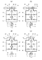
次に、図2(a)~(d)を参照して、手術用器具1の動作を説明する。なお、図1に示すようにジョー12が最大に開いた状態が待機状態である。
制御装置9に閉指令が入力されると、制御装置9は、図2(a)に示すようにピストン34が閉方向に移動するように駆動装置8を制御する。ジョー12が閉じるときの負荷が小さい場合は、図2(a)に示すように第1作動室31から第1給排路41を通じて第1圧力室21へ作動液が供給されるとともに、第2圧力室22から第2給排路42を通じて第2作動室32へ作動液が排出される。その結果、ジョー12が、ピストン34の移動に同期して閉じる。
ジョー12を閉じるときの負荷がある程度高くなると、図2(b)中に矢印で示すように液圧アクチュエータ2内で内部リークが生じる。これにより、ピストン34とジョー12の相対位置関係にズレが生じる。ジョー12を閉じるときの負荷がさらに高くなって第1給排路41の圧力がリリーフ弁5の設定圧(例えば、14~15MPa)を超えると、リリーフ弁5が開く。これにより、第1給排路41から、閉じ側流入路61、リリーフ弁5および閉じ側流出路63を経由して第2給排路42へ作動液が流れる。
その後、制御装置9に開指令が入力されると、制御装置9は、図2(c)に示すようにピストン34が開方向に移動するように駆動装置8を制御する。これにより、第2作動室32から第2給排路42を通じて第2圧力室22へ作動液が供給されるとともに、第1圧力室21から第1給排路41を通じて第1作動室31へ作動液が排出される。その結果、ジョー12が、ピストン34の移動に同期して開く。
制御装置9は、図2(d)に示すように、ジョー12が最大に開いた後もピストン34が開方向に移動するように駆動装置8を制御する。その結果、第2給排路42の圧力がリリーフ弁5の設定圧を超えたときにリリーフ弁5が開き、第2作動室32から排出された作動液が第2給排路42、開き側流入路65、リリーフ弁5、開き側流出路67および第1給排路41を経由して第1作動室31へ流れ込む。
このように、本実施形態では、ジョー12を最大開き位置に維持しながらピストン34を原点位置まで移動させることができる。これにより、ジョー12を閉じる際に液圧アクチュエータ2の内部リークによってジョー12とピストン34の相対位置関係にズレが生じたとしてもそれを是正する(換言すれば、相対位置関係を元に戻す)ことができる。これにより、ジョー11,12同士を押し付け合うのに必要なピストン34のストロークを常時確保することができる。
しかも、本実施形態では、リリーフ弁5から流出する作動液を加圧された状態で貯留するタンク7が設けられているので、リリーフ弁5の下流側の圧力をある程度高く保つことができる。これにより、リリーフ弁5が開いたときの第1作動室31または第2作動室32への作動液の流入を促進することができる。
(変形例)
本発明は上述した実施形態に限定されるものではなく、本発明の要旨を逸脱しない範囲で種々の変形が可能である。
本発明は上述した実施形態に限定されるものではなく、本発明の要旨を逸脱しない範囲で種々の変形が可能である。
例えば、液圧アクチュエータ2はシリンダタイプのものであってもよい。この場合、液圧アクチュエータ2は、双方のジョー11,12を開閉してもよい。
ただし、ベーンタイプの液圧アクチュエータは、シリンダタイプの液圧アクチュエータに比べて内部リークが大きい。従って、液圧アクチュエータ2がベーンタイプであれば、頻繁に発生し得るジョー12とピストン34の相対位置関係のズレを是正することができる。
また、前記実施形態のようにロッド83がシリンダ33の双方の端板を貫通する場合は、タンク7を省略してもよい。すなわち、ロッド83がシリンダ33の片方の端板のみを貫通する場合は、タンク7は必須の構成である。
また、閉じ側流入路61は省略可能である。この場合、開き側流入路65のチェック弁66も不要である。閉じ側流入路61を省略したとき、閉じ側流出路63は、第2給排路42の圧力が負圧とならないようにタンク7から第2給排路42へ圧力を供給する役割を果たす。さらに、上記のようにロッド83がシリンダ33の双方の端板を貫通する場合であってタンク7を省略する場合は、閉じ側流入路61だけでなく閉じ側流出路63も省略可能である。この場合、開き側流入路65のチェック弁66だけでなく開き側流出路67のチェック弁68も不要である。
ただし、前記実施形態のように閉じ側流入路61および閉じ側流出路63が設けられていれば、ジョー12を閉じる際に第1給排路41の圧力が高くなり過ぎたときに、第1給排路41から閉じ側流入路61、リリーフ弁5および閉じ側流出路63を経由して第2給排路42へ作動液を逃すことができる。
しかも、前記実施形態のように開き側流入路65、開き側流出路67、閉じ側流入路61および閉じ側流出路63にチェック弁62,64,66,68が設けられていれば、開き側流入路65および開き側流出路67にはジョー12を開くときのみに作動液が流れ、閉じ側流入路61および閉じ側流出路63にはジョー12を閉じるときのみに作動液が流れる。
(まとめ)
本発明の液圧式手術用器具は、少なくとも1つのジョーを閉じるための第1圧力室および前記少なくとも1つのジョーを開くための第2圧力室を含む液圧アクチュエータと、シリンダ、および前記シリンダの内部を第1作動室および第2作動室に仕切るピストンを含む給排装置と、前記第1作動室を前記第1圧力室と接続する第1給排路と、前記第2作動室を前記第2圧力室と接続する第2給排路と、リリーフ弁と、前記リリーフ弁の流入ポートを前記第2給排路と接続する開き側流入路と、前記リリーフ弁の流出ポートを前記第1給排路と接続する開き側流出路と、前記ピストンを前記第2作動室から前記第1作動室へ向かう閉方向および前記第1作動室から前記第2作動室へ向かう開方向へ移動する駆動装置と、前記駆動装置を制御する制御装置と、を備え、前記制御装置は、前記少なくとも1つのジョーを開く際に、前記少なくとも1つのジョーが最大に開いた後も前記ピストンが前記開方向へ移動するように前記駆動装置を制御する、ことを特徴とする。
本発明の液圧式手術用器具は、少なくとも1つのジョーを閉じるための第1圧力室および前記少なくとも1つのジョーを開くための第2圧力室を含む液圧アクチュエータと、シリンダ、および前記シリンダの内部を第1作動室および第2作動室に仕切るピストンを含む給排装置と、前記第1作動室を前記第1圧力室と接続する第1給排路と、前記第2作動室を前記第2圧力室と接続する第2給排路と、リリーフ弁と、前記リリーフ弁の流入ポートを前記第2給排路と接続する開き側流入路と、前記リリーフ弁の流出ポートを前記第1給排路と接続する開き側流出路と、前記ピストンを前記第2作動室から前記第1作動室へ向かう閉方向および前記第1作動室から前記第2作動室へ向かう開方向へ移動する駆動装置と、前記駆動装置を制御する制御装置と、を備え、前記制御装置は、前記少なくとも1つのジョーを開く際に、前記少なくとも1つのジョーが最大に開いた後も前記ピストンが前記開方向へ移動するように前記駆動装置を制御する、ことを特徴とする。
上記の構成によれば、ジョーが最大に開いた後もピストンが開方向へ移動するので、第2給排路の圧力がリリーフ弁の設定圧を超えたときにリリーフ弁が開き、第2作動室から排出された作動液が第2給排路、開き側流入路、リリーフ弁、開き側流出路および第1給排路を経由して第1作動室へ流れ込む。すなわち、ジョーを最大開き位置に維持しながらピストンを原点位置まで移動させることができる。これにより、ジョーを閉じる際に液圧アクチュエータの内部リークによってジョーとピストンの相対位置関係にズレが生じたとしてもそれを是正する(換言すれば、相対位置関係を元に戻す)ことができる。
前記液圧アクチュエータは、前記第1圧力室と前記第2圧力室を仕切る、揺動するベーンを含んでもよい。ベーンタイプの液圧アクチュエータは、シリンダタイプの液圧アクチュエータに比べて内部リークが大きい。従って、液圧アクチュエータがベーンタイプであれば、頻繁に発生し得るジョーとピストンの相対位置関係のズレを是正することができる。
上記の液圧式手術用器具は、前記リリーフ弁の流入ポートを前記第1給排路と接続する閉じ側流入路と、前記リリーフ弁の流出ポートを前記第2給排路と接続する閉じ側流出路と、をさらに備え、前記開き側流入路には、前記第2給排路から前記リリーフ弁へ向かう流れは許容するがその逆の流れは禁止するチェック弁が設けられており、前記開き側流出路には、前記リリーフ弁から前記第1給排路へ向かう流れは許容するがその逆の流れは禁止するチェック弁が設けられており、前記閉じ側流入路には、前記第1給排路から前記リリーフ弁へ向かう流れは許容するがその逆の流れは禁止するチェック弁が設けられており、前記閉じ側流出路には、前記リリーフ弁から前記第2給排路へ向かう流れは許容するがその逆の流れは禁止するチェック弁が設けられてもよい。この構成によれば、ジョーを閉じる際に第1給排路の圧力が高くなり過ぎたときに、第1給排路から閉じ側流入路、リリーフ弁および閉じ側流出路を経由して第2給排路へ作動液を逃すことができる。しかも、開き側流入路、開き側流出路、閉じ側流入路および閉じ側流出路にはチェック弁が設けられているので、開き側流入路および開き側流出路にはジョーを開くときのみに作動液が流れ、閉じ側流入路および閉じ側流出路にはジョーを閉じるときのみに作動液が流れる。
上記の液圧式手術用器具は、前記リリーフ弁の流出ポートと接続された、前記リリーフ弁から流出する作動液を加圧された状態で貯留するタンクをさらに備えてもよい。この構成によれば、リリーフ弁の下流側の圧力をある程度高く保つことができ、リリーフ弁が開いたときの第1作動室または第2作動室への作動液の流入を促進することができる。
例えば、前記駆動装置は、電動モータと、前記電動モータの回転運動を前記ピストンの直線運動に変換する直動機構を含んでもよい。
Claims (5)
- 少なくとも1つのジョーを閉じるための第1圧力室および前記少なくとも1つのジョーを開くための第2圧力室を含む液圧アクチュエータと、
シリンダ、および前記シリンダの内部を第1作動室および第2作動室に仕切るピストンを含む給排装置と、
前記第1作動室を前記第1圧力室と接続する第1給排路と、
前記第2作動室を前記第2圧力室と接続する第2給排路と、
リリーフ弁と、
前記リリーフ弁の流入ポートを前記第2給排路と接続する開き側流入路と、
前記リリーフ弁の流出ポートを前記第1給排路と接続する開き側流出路と、
前記ピストンを前記第2作動室から前記第1作動室へ向かう閉方向および前記第1作動室から前記第2作動室へ向かう開方向へ移動する駆動装置と、
前記駆動装置を制御する制御装置と、を備え、
前記制御装置は、前記少なくとも1つのジョーを開く際に、前記少なくとも1つのジョーが最大に開いた後も前記ピストンが前記開方向へ移動するように前記駆動装置を制御する、液圧式手術用器具。 - 前記液圧アクチュエータは、前記第1圧力室と前記第2圧力室を仕切る、揺動するベーンを含む、請求項1に記載の液圧式手術用器具。
- 前記リリーフ弁の流入ポートを前記第1給排路と接続する閉じ側流入路と、
前記リリーフ弁の流出ポートを前記第2給排路と接続する閉じ側流出路と、をさらに備え、
前記開き側流入路には、前記第2給排路から前記リリーフ弁へ向かう流れは許容するがその逆の流れは禁止するチェック弁が設けられており、
前記開き側流出路には、前記リリーフ弁から前記第1給排路へ向かう流れは許容するがその逆の流れは禁止するチェック弁が設けられており、
前記閉じ側流入路には、前記第1給排路から前記リリーフ弁へ向かう流れは許容するがその逆の流れは禁止するチェック弁が設けられており、
前記閉じ側流出路には、前記リリーフ弁から前記第2給排路へ向かう流れは許容するがその逆の流れは禁止するチェック弁が設けられている、請求項1または2に記載の液圧式手術用器具。 - 前記リリーフ弁の流出ポートと接続された、前記リリーフ弁から流出する作動液を加圧された状態で貯留するタンクをさらに備える、請求項1~3の何れか一項に記載の液圧式手術用器具。
- 前記駆動装置は、電動モータと、前記電動モータの回転運動を前記ピストンの直線運動に変換する直動機構を含む、請求項1~4の何れか一項に記載の液圧式手術用器具。
Applications Claiming Priority (2)
| Application Number | Priority Date | Filing Date | Title |
|---|---|---|---|
| JP2020-218630 | 2020-12-28 | ||
| JP2020218630A JP2022103784A (ja) | 2020-12-28 | 2020-12-28 | 液圧式手術用器具 |
Publications (1)
| Publication Number | Publication Date |
|---|---|
| WO2022145103A1 true WO2022145103A1 (ja) | 2022-07-07 |
Family
ID=82259410
Family Applications (1)
| Application Number | Title | Priority Date | Filing Date |
|---|---|---|---|
| PCT/JP2021/037839 Ceased WO2022145103A1 (ja) | 2020-12-28 | 2021-10-13 | 液圧式手術用器具 |
Country Status (2)
| Country | Link |
|---|---|
| JP (1) | JP2022103784A (ja) |
| WO (1) | WO2022145103A1 (ja) |
Citations (2)
| Publication number | Priority date | Publication date | Assignee | Title |
|---|---|---|---|---|
| US5361583A (en) * | 1993-09-30 | 1994-11-08 | Ethicon, Inc. | Pressurized fluid actuation system with variable force and stroke output for use in a surgical instrument |
| JP2006500986A (ja) * | 2002-09-30 | 2006-01-12 | サイトライン テクノロジーズ リミテッド | ピストンにより駆動される内視鏡ツール |
-
2020
- 2020-12-28 JP JP2020218630A patent/JP2022103784A/ja active Pending
-
2021
- 2021-10-13 WO PCT/JP2021/037839 patent/WO2022145103A1/ja not_active Ceased
Patent Citations (2)
| Publication number | Priority date | Publication date | Assignee | Title |
|---|---|---|---|---|
| US5361583A (en) * | 1993-09-30 | 1994-11-08 | Ethicon, Inc. | Pressurized fluid actuation system with variable force and stroke output for use in a surgical instrument |
| JP2006500986A (ja) * | 2002-09-30 | 2006-01-12 | サイトライン テクノロジーズ リミテッド | ピストンにより駆動される内視鏡ツール |
Also Published As
| Publication number | Publication date |
|---|---|
| JP2022103784A (ja) | 2022-07-08 |
Similar Documents
| Publication | Publication Date | Title |
|---|---|---|
| US5339723A (en) | Pressurized fluid actuation system for amplifying operator input force in a surgical instrument | |
| US8973890B2 (en) | Fluid-operated actuating drive on a valve | |
| US20230356557A1 (en) | Hydraulic Fluid Supply System, In Particular For A Suspension System | |
| CN104251240B (zh) | 具有紧急功能的液压操作装置的四腔缸及其液压操作装置 | |
| JP7575213B2 (ja) | 複動空気圧シリンダ用流体戻し装置及び複動空気圧シリンダの動作方法 | |
| JP6788395B2 (ja) | シリンダ駆動装置 | |
| CN120042821A (zh) | 一种主被动结合的电液执行器及其方法 | |
| JP2005249048A (ja) | 背圧弁及びアクチュエーションシステム | |
| JP2022103784A (ja) | 液圧式手術用器具 | |
| JP7547467B2 (ja) | 整形器具又は人工装具用の油圧アクチュエータ、及び人工補整装置 | |
| US11859724B2 (en) | Check valve | |
| JP6093535B2 (ja) | シリンダ駆動装置 | |
| CN117425778B (zh) | 进气阀系统 | |
| US20080054203A1 (en) | Valve arrangement | |
| WO2022145104A1 (ja) | 液圧式手術用器具 | |
| JP2008157407A5 (ja) | ||
| KR102941468B1 (ko) | 액추에이터 제어 장치 | |
| WO2018025546A1 (ja) | 油圧駆動装置 | |
| JP6796291B2 (ja) | エアシリンダ | |
| JP6703742B2 (ja) | 破砕機及びこれを備えた油圧駆動装置 | |
| JP2024071218A5 (ja) | ||
| JP2001165113A (ja) | エアクッション機構付きリニアアクチュエーター | |
| JP2002022054A (ja) | 方向制御弁 | |
| JP6613935B2 (ja) | 油圧駆動装置 | |
| JP2010025236A (ja) | 流体圧アクチュエータの飛出し防止装置 |
Legal Events
| Date | Code | Title | Description |
|---|---|---|---|
| 121 | Ep: the epo has been informed by wipo that ep was designated in this application |
Ref document number: 21914964 Country of ref document: EP Kind code of ref document: A1 |
|
| NENP | Non-entry into the national phase |
Ref country code: DE |
|
| 122 | Ep: pct application non-entry in european phase |
Ref document number: 21914964 Country of ref document: EP Kind code of ref document: A1 |