WO2022145086A1 - 細胞移動装置 - Google Patents
細胞移動装置 Download PDFInfo
- Publication number
- WO2022145086A1 WO2022145086A1 PCT/JP2021/031546 JP2021031546W WO2022145086A1 WO 2022145086 A1 WO2022145086 A1 WO 2022145086A1 JP 2021031546 W JP2021031546 W JP 2021031546W WO 2022145086 A1 WO2022145086 A1 WO 2022145086A1
- Authority
- WO
- WIPO (PCT)
- Prior art keywords
- cell
- head
- movement
- chip
- tip portion
- Prior art date
- Legal status (The legal status is an assumption and is not a legal conclusion. Google has not performed a legal analysis and makes no representation as to the accuracy of the status listed.)
- Ceased
Links
Images


Classifications
-
- C—CHEMISTRY; METALLURGY
- C12—BIOCHEMISTRY; BEER; SPIRITS; WINE; VINEGAR; MICROBIOLOGY; ENZYMOLOGY; MUTATION OR GENETIC ENGINEERING
- C12M—APPARATUS FOR ENZYMOLOGY OR MICROBIOLOGY; APPARATUS FOR CULTURING MICROORGANISMS FOR PRODUCING BIOMASS, FOR GROWING CELLS OR FOR OBTAINING FERMENTATION OR METABOLIC PRODUCTS, i.e. BIOREACTORS OR FERMENTERS
- C12M33/00—Means for introduction, transport, positioning, extraction, harvesting, peeling or sampling of biological material in or from the apparatus
- C12M33/04—Means for introduction, transport, positioning, extraction, harvesting, peeling or sampling of biological material in or from the apparatus by injection or suction, e.g. using pipettes, syringes, needles
-
- B—PERFORMING OPERATIONS; TRANSPORTING
- B01—PHYSICAL OR CHEMICAL PROCESSES OR APPARATUS IN GENERAL
- B01L—CHEMICAL OR PHYSICAL LABORATORY APPARATUS FOR GENERAL USE
- B01L3/00—Containers or dishes for laboratory use, e.g. laboratory glassware; Droppers
- B01L3/02—Burettes; Pipettes
- B01L3/021—Pipettes, i.e. with only one conduit for withdrawing and redistributing liquids
- B01L3/0217—Pipettes, i.e. with only one conduit for withdrawing and redistributing liquids of the plunger pump type
- B01L3/022—Capillary pipettes, i.e. having very small bore
-
- G—PHYSICS
- G01—MEASURING; TESTING
- G01N—INVESTIGATING OR ANALYSING MATERIALS BY DETERMINING THEIR CHEMICAL OR PHYSICAL PROPERTIES
- G01N35/00—Automatic analysis not limited to methods or materials provided for in any single one of groups G01N1/00 - G01N33/00; Handling materials therefor
- G01N35/10—Devices for transferring samples or any liquids to, in, or from, the analysis apparatus, e.g. suction devices, injection devices
- G01N35/1009—Characterised by arrangements for controlling the aspiration or dispense of liquids
- G01N35/1011—Control of the position or alignment of the transfer device
Definitions
- the present invention relates to a cell transfer device that uses a suction tip to peel off cells attached to the bottom surface of a container, suck them, and move them to a predetermined location.
- a work plate for inspection, observation, etc. is performed from a culture plate for culturing single cells, cell colonies, etc. (in the present specification, these may be simply referred to as "cells").
- Work may be performed to move the cells to.
- the required cells are picked from the wells of the culture plate, and the picked cells are transferred to the wells of the working plate.
- Patent Document 1 discloses a fishing fungus device that automates picking work. This fishing fungus device is configured to perform picking by moving the fishing fungus tool horizontally in a state of being close to or in contact with the culture medium surface and scraping the cells adhering to the culture medium surface with the fishing fungus tool. Has been done.
- the tip of the chip even if the tip of the chip is lowered to a certain height position and moved horizontally, there may be a case where the cells adhering to the concave portion on the bottom surface cannot be peeled off. If the tip tip is lowered so as to match the deepest recess on the bottom surface, the tip tip may be supported by the bottom surface and the tip may not be able to move. Further, the height position of the cell on the bottom surface is obtained from the focusing information of the observation image of the cell, but the accurate cell height position can be obtained due to the influence of the error of the observation lens and the depth of field. It may not be possible. In this case, the descending position of the tip of the chip cannot be set accurately, and as a result, the cells may not be stripped.
- An object of the present invention is to provide a cell transfer device capable of reliably stripping cells from the bottom surface of a container and performing accurate cell picking.
- the cell transfer device is equipped with a chip having a tip having an opening through which cells can enter and exit, and has a mechanism for sucking and ejecting the cells into the chip through the opening. It includes a head that can move in a three-dimensional direction and a control unit that controls the movement of the head.
- the control unit can execute a stripping control in which the chip is made to perform an operation of stripping cells adhering to the bottom surface of the cell storage container through the head, and in the stripping control, the tip portion of the chip is subjected to the stripping control.
- the head is controlled so that the tip portion of the chip performs movement including a horizontal component at each of different positions in the vertical direction including a position in contact with cells attached to the bottom surface.
- FIG. 1 is a diagram schematically showing a configuration example of a cell migration device according to an embodiment of the present invention.
- FIG. 2A is a cross-sectional view of a tip mounted on the head
- FIG. 2B is a cross-sectional view of the tip during a suction operation
- C) is an enlarged view of a main part of FIG. 2 (B).
- FIG. 3 is a block diagram showing the electrical configuration of the cell migration device.
- 4 (A) and 4 (B) are diagrams for explaining the problems of the conventional cell stripping operation.
- 5 (A) to 5 (F) are diagrams showing a cell stripping operation.
- FIG. 6A is a diagram showing a stripping operation when the tip tip portion is gradually separated from the bottom surface
- FIG. 6A is a diagram showing a stripping operation when the tip tip portion is gradually separated from the bottom surface
- FIG. 6A is a diagram showing a stripping operation when the tip tip portion is gradually separated from the bottom surface
- FIG. 6B is a diagram showing a stripping operation when the tip end portion is gradually approached to the bottom surface.
- FIG. 7 is a diagram showing another example of the cell stripping operation.
- 8 (A) to 8 (D) are diagrams showing specific examples of horizontal movement of the chip in the cell stripping operation.
- 9 (A) to 9 (G) are diagrams showing specific examples of horizontal movement of the chip when some cells are stripped from the cell colony.
- 10 (A) to 10 (E) are diagrams showing other examples of horizontal movement of the chip in the cell stripping operation.
- FIG. 11 is a flowchart showing an operation during cell pickup and migration using the cell migration device.
- FIG. 12 is a diagram showing another example of the cell stripping operation.
- 13 (A) to 13 (C) are views showing another example of the cell stripping operation.
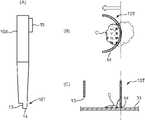
- 14 (A) to 14 (C) are views showing a modified example of the chip and a cell stripping operation when the chip is used.
- the cell migration device can pick and migrate cells derived from various living organisms.
- Living body-derived cells include, for example, single cells such as blood cell lines and single cells, tissue fragments such as Histoculture, cell aggregates such as spheroids and organoids, individuals such as zebrafish, nematodes, and fertilized eggs, and 2D or 3D cells. Cell colonies and the like.
- the term "cell” includes these various cells.
- the cell transfer apparatus of the present invention is suitable for picking and migrating cells such as single cells, cell aggregates, and cell colonies, which generally require picking under a microscope. In the embodiment described below, mainly cell colonies are assumed as picking targets. Cell colonies are sometimes referred to simply as cell C in the detailed description.
- FIG. 1 is a diagram schematically showing an overall configuration of a cell migration device S according to an embodiment of the present invention.
- a cell transfer device S for moving cells C between two containers that is, between a culture plate 2 and a destination plate 4, is illustrated.
- the cell migration device S may be configured to transfer the cell C between three or more containers.
- the cell transfer device S includes a translucent base 1 having a horizontal mounting surface, a camera unit 5 arranged on the lower side of the base 1, and a head unit 6 arranged on the upper side of the base 1. And include.
- the culture plate 2 that is the migration source of the cells C is placed in the first placement position P1 of the base 1, and the migration destination plate 4 that is the migration destination of the cells C is placed in the second placement position P2.
- the head unit 6 includes a plurality of heads 61 that can be raised and lowered in the Z direction (vertical direction).
- a chip 10 for sucking and discharging cells C is attached to the lower end of each head 61.
- the camera unit 5 and the head unit 6 can be moved in the X direction (horizontal direction) and in the direction perpendicular to the paper surface of FIG. 1 (Y direction).
- the culture plate 2 and the destination plate 4 are placed on the upper surface of the base 1 within the movable range of the head unit 6.
- the cell transfer device S performs picking in which cells C are individually sucked from each of the plurality of chips 10 from the culture plate 2 in which a large number of cells C are cultured. Then, the picked cells C are moved to the destination plate 4, and the cells C are discharged from the plurality of chips 10 into the destination plate 4 (well 41). Prior to picking the cells C, the cells C held in the culture plate 2 are imaged by the camera unit 5, and a sorting operation of selecting high-quality cells C to be transferred to the destination plate 4 is performed.
- the base 1 is a rectangular flat plate having a predetermined rigidity, and a part or all of the base 1 is made of a translucent material.
- the preferred base 1 is a glass plate.
- the culture plate 2 is a container from which cells C move, and is provided with a plurality of wells 3 (cell storage containers) for culturing cells C.
- Each well 3 is a small container with a top opening and has a flat bottom surface 31.
- Cultured cells C are implanted on the bottom surface 31.
- a liquid medium 32 is injected into the well 3.
- Test cells are seeded in well 3 and cultured for a predetermined period to be colonized.
- a member made of a translucent resin material or glass is used in order to enable imaging of cells C by the camera unit 5 arranged below.
- a commercially available 6-well plate for example, model number 3516 manufactured by Corning Inc.
- the destination plate 4 has a plurality of wells 41 from which the picked cells C are discharged from the culture plate 2.
- the well 41 is a bottomed hole opened on the upper surface of the destination plate 4.
- One well 41 contains a required number (usually one) of cells C along with a liquid medium. Various tests, observations, cultures, etc. such as addition of reagents and reactants are performed on the cells C housed in the well 41.
- a member made of a translucent resin material or glass is used as the destination plate 4, for example, a commercially available 96-well plate (for example, model number 3595 manufactured by Corning Inc.) can be used.
- the camera unit 5 is a device that captures an image of cells C held on the culture plate 2 or the destination plate 4 from the lower surface side thereof, and includes a lens unit 51 and a camera body 52.
- the lens unit 51 is an objective lens used in an optical microscope, and includes a lens group for forming an optical image having a predetermined magnification and a lens barrel accommodating the lens group.
- the camera body 52 includes an image pickup element such as a CCD image sensor.
- the lens unit 51 forms an image of an image of an image pickup object on the light receiving surface of the image pickup device.
- the camera unit 5 can move in the X direction and the Y direction below the base 1 along the guide rail 5G extending in the left-right direction in parallel with the base 1. Further, the lens unit 51 is movable in the Z direction for focusing operation.
- the head unit 6 is a device provided for picking cells C from the culture plate 2 and moving them to the destination plate 4.
- the head unit 6 includes a plurality of heads 61 and a head body 62 to which these heads 61 are assembled.
- a suction tip 10 for sucking and discharging cells C is attached to the tip of each head 61.
- the head body 62 holds the head 61 so as to be able to move up and down in the + Z and ⁇ Z directions (vertical direction), and can move in the + X and ⁇ X directions (horizontal direction) along the guide rail 6G.
- the head body 62 can also be moved in the Y direction. That is, the head 61 can move in the three-dimensional direction of XYZ.
- FIG. 2A is a cross-sectional view of a chip 10 mounted on the head 61, and is a diagram showing a moving mechanism and a suction mechanism of the chip 10.
- the chip 10 is a tool for sucking or ejecting the cell C for the movement of the cell C, and includes a tip portion 10T having a tip opening t through which the cell C can enter and exit.
- the tip 10 of the present embodiment comprises an assembly of a syringe 11 and a plunger 12.
- the syringe 11 is internally provided with a tubular passage 11P that serves as a suction path for cells C.
- the plunger 12 moves back and forth in the tubular passage 11P while sliding in contact with the inner peripheral wall of the syringe 11 defining the tubular passage 11P.
- the syringe 11 includes a syringe base end 111 made of a large-diameter cylinder and a syringe body 112 made of a small-diameter long cylinder.
- the tubular passage 11P is formed in the syringe body 112.
- the above-mentioned tip opening t is provided in the syringe tip 113, which is the lower end of the syringe body 112.
- One end of the tubular passage 11P is connected to the tip opening t.
- the syringe base end portion 111 is continuously provided on the other end side of the syringe body portion 112 via a tapered portion.
- the upper end portion of the syringe base end portion 111 is fitted and mounted on the lower end portion of the head 61.
- the plunger 12 includes a plunger base end portion 121 made of a cylindrical body, a needle-shaped plunger main body portion 122 connected below the plunger base end portion 121, and a plunger tip portion 123 which is the lower end of the plunger main body portion 122.
- the plunger 12 is assembled to the syringe 11 in such a manner that the plunger base end portion 121 is housed in the syringe base end portion 111 and the plunger main body portion 122 is inserted into the tubular passage 11P of the syringe main body portion 112.
- the plunger tip 123 protrudes from the tip opening t.
- a rod 61R that can move in the vertical direction in the internal space of the head 61 is attached to the upper end of the plunger base end portion 121.
- the head drive unit 64 which functions as a mechanism for moving the chip 10 in the vertical direction with respect to the head 61 and a mechanism for sucking and ejecting cells C into the chip 10 through the tip opening t of the chip 10, is provided in the head body 62. It is equipped in.
- the head drive unit 64 includes a head elevating motor 641 and a plunger elevating motor 642.
- the head elevating motor 641 is a motor that serves as a drive source for elevating and lowering the head 61 with respect to the head body 62.
- the tip 10 mounted on the lower end of the head 61 is also moved up and down. That is, the height position of the tip opening t of the tip portion 10T can be set to a desired position by controlling the operation of the head elevating motor 641.
- the plunger elevating motor 642 is a motor that serves as a drive source for elevating and lowering the rod 61R in the internal space of the head 61.
- the plunger 12 attached to the rod 61R is also raised and lowered.
- a suction force is generated at the tip opening t.
- a discharge force is generated at the tip opening t. That is, by controlling the operation of the plunger elevating motor 642, it is possible to control the suction operation and the discharge operation of the cells C by the chip 10.
- FIG. 2A shows the state in which the plunger 12 is most lowered. This state is a state before the aspiration of the cells C, or a state in which the aspirated cells C are discharged to the chip 10.
- the plunger tip 123 projects slightly downward from the syringe tip 113.
- FIG. 2B shows a state in which the plunger 12 is raised by a predetermined height. This state is the state of the chip 10 at the time of the suction operation for sucking the cells C.
- FIG. 2C shows an enlarged view of the main part of FIG. 2B.
- the plunger tip 123 is submerged inside the tubular passage 11P. At this time, a suction force is generated at the tip opening t, and the fluid around the tip opening t is sucked into the suction space H formed in the tubular passage 11P by the infiltration of the plunger tip portion 123. That is, the medium 32 containing the cells C is held in the suction space H.
- the plunger 12 is moved downward after this suction operation, the fluid held in the suction space H is discharged from the tip opening t.
- the suction amount of the fluid can be adjusted by the ascending height of the plunger 12, and the suction speed of the fluid can be adjusted by the ascending speed of the plunger 12.
- the chip 10 may be made of resin, metal, or glass. However, it is desirable that at least one of the chip 10 or the culture plate 2 (well 3) is made of an elastically deformable member. As will be described in detail later, in the present embodiment, the tip portion 10T of the tip 10 may come into contact with the bottom surface 31 of the well 3 relatively strongly. If either or both of the chip 10 and the culture plate 2 are elastically deformed, the possibility that they will be damaged at the time of the contact can be reduced. Further, if the tip portion 10T is brought into contact with the bottom surface 31 with an appropriate pressing force, a strong rubbing force based on the elastic deformation force can be applied between the two. Thereby, the peeling force from the bottom surface 31 of the cell C can be enhanced.
- FIG. 3 is a block diagram showing the electrical configuration of the cell migration device S.
- the cell movement device S includes a control unit 7 that controls the movement of the head unit 6 (see FIG. 1) and the raising and lowering of the head 61 (chip 10), that is, the movement of the head 61 in the three-dimensional direction.
- the control unit 7 controls the suction and discharge operations of the cells C to the chip 10, the movement of the camera unit 5, the imaging operation, and the like.
- the cell moving device S includes a camera shaft drive unit 53, a servomotor 54, a head unit shaft drive unit 63, and a head drive unit 64.
- the camera shaft drive unit 53 includes a drive motor that horizontally moves the camera unit 5 along the guide rail 5G (FIG. 1).
- the servomotor 54 rotates in the forward direction or the reverse direction to move the lens portion 51 in the vertical direction with a predetermined resolution via the power transmission mechanism (not shown). As a result, the focal position of the lens portion 51 is aligned with the cells C housed in the well 3.
- the base 1 side may be moved up and down instead of the lens portion 51.
- the head unit shaft drive unit 63 includes a drive motor that horizontally moves the head unit 6 (head body 62) in the X or Y direction along the guide rail 6G.
- the head drive unit 64 is as described above based on FIG.
- the control unit 7 is composed of a microcomputer or the like, and by executing a predetermined program, the axis control unit 71, the head control unit 72, the image pickup control unit 73, the image processing unit 74, the storage unit 75, and the main control unit 78 are combined. Functions to prepare. Further, the control unit 7 is provided with an input unit 76 for inputting various information and a display unit 77 for displaying various information. The input unit 76 receives input of various operation information from the operator. In the present embodiment, the input unit 76 also functions as a terminal that receives an input related to the selection operation of the cell C. The display unit 77 functions as a monitor for displaying an image or the like captured by the camera unit 5.
- the shaft control unit 71 controls the operation of the head unit shaft drive unit 63.
- the shaft control unit 71 controls the head unit shaft drive unit 63 to move the head unit 6 to a predetermined target position in the horizontal direction.
- the movement of the head 61 (chip 10) between the culture plate 2 and the destination plate 4, the vertical positioning of the cells C housed in the well 3, and the vertical positioning of the head 61 (chip 10) with respect to the well 41 to be ejected. Etc. are realized by the control of the head unit shaft drive unit 63 by the shaft control unit 71.
- the axis control unit 71 controls the camera axis drive unit 53 to control the operation of moving the camera unit 5 along the guide rail 5G. Further, the horizontal movement of the head 61 in the cell C stripping control described later is also controlled by the axis control unit 71.
- the head control unit 72 controls the head elevating motor 641 of the head drive unit 64 to raise and lower the head 61 to be controlled toward a predetermined target position. Further, the head control unit 72 controls the plunger elevating motor 642 to generate a suction force or a discharge force at the tip opening t of the tip 10 at a predetermined timing.
- the image pickup control unit 73 controls the image pickup operation of the culture plate 2 or the destination plate 4 by the camera unit 5, for example, the exposure amount and the shutter timing. Further, the image pickup control unit 73 gives the servomotor 54 a control pulse for moving the lens unit 51 in the vertical direction at a predetermined pitch (for example, a pitch of several tens of ⁇ m) for the focusing operation.
- a predetermined pitch for example, a pitch of several tens of ⁇ m
- the image processing unit 74 performs image processing such as edge detection processing and pattern recognition processing accompanied by feature amount extraction on the image data acquired by the camera body 52.
- the image processing unit 74 executes a process of recognizing the presence of the cell C on the bottom surface 31 on the image based on the image of the culture plate 2 in which the cell C is cultured.
- the image processing unit 74 executes a process of recognizing the number, amount, fluorescence intensity, etc. of the cells C contained in the well 41 based on the image of the well 41 to which the cells C have been moved.
- the storage unit 75 stores various set values, data, programs, etc. in the cell transfer device S.
- the storage unit 75 stores information about the culture plate 2 to be used, for example, data such as the plate size, the size of the well 3, and the unevenness range on the bottom surface 31.
- setting information such as the suction amount and suction speed in the suction operation of the cell C, the horizontal movement pattern of the head in the stripping control, the movement pitch in the Z direction, and the like are also stored in the storage unit 75.
- the main control unit 78 comprehensively controls the operations of the camera unit 5 and the head unit 6.
- the main control unit 78 causes the culture plate 2 to be imaged, picks the cells C selected as the movement target to be sucked by the chip 10 mounted on the head 61, and moves the cells C to the destination plate 4.
- the camera unit 5 and the head unit 6 are controlled through the axis control unit 71, the head control unit 72, and the image pickup control unit 73. Further, in addition to such integrated control, the main control unit 78 executes a stripping control for stripping the cells C to be moved attached to the bottom surface 31 of the well 3 to the chip 10 through the head 61.
- the main control unit 78 functionally includes a cell position specifying unit 781, a picking control unit 782, and a setting unit 783 for the stripping control described above.
- the cell position specifying unit 781 performs a process of acquiring the position information (XY coordinates) of the cell C on the bottom surface 31 specified by the image processing unit 74 and the height (thickness) information of the cell C.
- the picking control unit 782 generates control signals for horizontal movement, vertical movement, and suction operation of the head 61 based on the setting information and the like stored in the storage unit 75, and gives them to the axis control unit 71 and the head control unit 72. ..
- the setting unit 783 sets information necessary for stripping control according to the performance of the chip 10 and the lens unit 51 to be used.
- the bottom surface 31 of the well 3 has a non-negligible height variation, that is, surface irregularities.
- the thickness size of the cell C to be picked is, for example, about several microns.
- the bottom surface 31 is macroscopically a horizontal plane, but when observed on the order of microns, surface irregularities on the order of several microns to several tens of microns exist. Further, as measured by the present inventor, it was confirmed that the height of the bottom surface 31 of the well 3 of the commercially available 6-well plate has a height difference of 90 ⁇ m at the maximum among the 6 wells. When such a height variation of the bottom surface 31 exists, even if the tip portion 10T of the chip 10 is lowered to a certain height position and moved in the horizontal direction, the cells C may not be scraped off. be.
- the well 3 includes a first bottom surface 31g1 at a certain height position and a second bottom surface 31g2 at a height position lower than the first bottom surface 31g1 by a height difference g.
- the first bottom surface 31g1 and the second bottom surface 31g2 are provided in the bottom surface 31 of one well 3, or in one well 3 and another well 3 included in one culture plate 2. It is assumed that the height difference g is larger than the thickness of the cell C.
- the descending height of the tip portion 10T of the chip 10 is set to the height position of the first bottom surface 31g1 and the cell C stripping operation is executed.
- the cells C attached to the first bottom surface 31g1 can be scraped off by the horizontal movement of the tip portion 10T.
- the cells C attached to the second bottom surface 31g2 cannot be scraped off because they are located at a position lower than the horizontally moving tip portion 10T.
- FIG. 4B shows a situation when the descending height of the tip portion 10T of the chip 10 is set to the height position of the second bottom surface 31g2 and the cell C stripping operation is executed.
- the cells C attached to the second bottom surface 31g2 can be scraped off by the horizontal movement of the tip portion 10T.
- the lowering is excessive, and the tip portion 10T strongly abuts on the first bottom surface 31g1.
- FIG. 4B illustrates a state in which the first bottom surface 31g1 is pressed by the tip portion 10T and is curved and deformed downward.
- the tip portion 10T may be supported by the first bottom surface 31g1 and the tip portion 10T may not move horizontally. As a result, it is difficult to reliably scrape off the cells C adhering to the first bottom surface 31g1.
- the depth of field of the lens portion 51 of the camera unit 5 also affects the accuracy of the stripping operation.
- the implantation position of the cell C on the bottom surface 31 can be obtained from the in-focus position information of the two-dimensional image of the cell C captured by the camera unit 5. For example, it is possible to know the height position of the cell C based on the height position of the body-attached surface of the lens portion 51 with respect to the reference plane when the in-focus image of the cell C is obtained.
- the lens portion 51 has a depth of field, an error is present in the height position of the cell C obtained from the in-focus position information. Due to this error, there may be a case where the tip portion 10T cannot hit the cell C during the stripping operation.
- the stripping control according to the present embodiment aims to eliminate such a problem.
- the picking control unit 782 of the main control unit 78 controls the head 61 so as to move the head 61 at a plurality of positions different in the vertical direction, each including a horizontal component. It is desirable that each of the different positions in the vertical direction is a position where the tip portion 10T of the chip 10 is in contact with the cell C attached to the bottom surface 31. However, the tip portion 10T does not have to be in contact with the cell C at all positions, and the tip portion 10T may be in contact with the cell C at at least one of the plurality of vertical positions set by the picking control unit 782. That is, the above-mentioned "positions different in the vertical direction" may include the position where the tip portion 10T is in contact with the cell C attached to the bottom surface 31.
- the steps (A) to (F) shown in FIG. 5 are diagrams showing the cell C stripping operation in sequence.
- the step (A) is a step of aligning the tip portion 10T of the chip 10 with a cell piece Ca to be picked, that is, a part intended to be cut from the cell C, above the cell C.
- the axis control unit 71 drives the head unit axis drive unit 63 under the control of the picking control unit 782 based on the XY coordinate information of the cell piece Ca specified by the cell position identification unit 781, and the head unit. 6 is moved in the XY direction.
- the step (B) is a step of lowering the tip portion 10T of the chip 10 to the first position in the vertical direction.
- the first position a position where the tip portion 10T abuts on the bottom surface 31 is exemplified.
- the head control unit 72 drives the head elevating motor 641 of the head drive unit 64 under the control of the picking control unit 782, and lowers the head 61 in the vertical direction.
- the tip portion 10T penetrates the cell C, so that a notch is formed around the cell piece Ca.
- the height position of the bottom surface 31, that is, the height position of the cell C is obtained from the in-focus position information of the image captured by the camera unit 5.
- the head 61 is lowered in consideration of the above-mentioned depth of field. That is, since there is a possibility that an error intervenes in the height position of the cell C by the depth of field, the depth of field is added to the height position of the cell C specified by the cell position specifying unit 781.
- the picking control unit 782 lowers the head 61 to the head elevating motor 641 by the distance.
- the height position of the cell C is not recognized, only the distance obtained by adding the variation in the height position of the bottom surface 31 obtained in advance by actual measurement or specification value to the height position of the bottom surface 31. , The head 61 is lowered. In these cases, one or both of them may be elastically deformed due to the contact between the chip 10 and the bottom surface 31.
- the step (C) is a step of causing the chip 10 to perform a movement including a horizontal component (first horizontal movement) at the first position.
- the shaft control unit 71 drives the head unit shaft drive unit 63 under the control of the picking control unit 782, and the head unit 6 is moved in the XY directions to move the head 61 including a horizontal component. Let me. This movement may cause the tip 10 to bend.
- a pause time may be provided to freeze the start of the next step only for several tens to several hundreds of milliseconds after the execution of the step (C).
- the execution of the step (C) acts to move the cell piece Ca relative to the bottom surface 31 at the tip portion 10T, and contributes to stripping the cell piece Ca from the bottom surface 31.
- the step (D) is a step of raising the tip portion 10T of the chip 10 from the first position to the second position in the vertical direction.
- the head control unit 72 drives the head elevating motor 641 and raises the head 61 in the vertical direction by the pitch d.
- the step (E) is a step of causing the chip 10 to move including a horizontal component (second horizontal movement) at the second position.
- the operation of the mechanism is the same as that in the step (C).
- the operations of the steps (C) to (E) can be repeated until the tip portion 10T of the chip 10 rises by the amount of the height variation of the bottom surface 31.
- the steps (C) to (E) can be repeated only 90 ⁇ m / d times.
- the number of repetitions of the operations of steps (C) to (E) can be arbitrarily set in consideration of the movement time of the head 61 (chip 10) from the culture plate 2 to the destination plate 4.
- the step (F) is a step of sucking the cell debris Ca peeled off from the bottom surface 31 into the chip 10.
- the cell pieces Ca stripped from the bottom surface 31 have reached a state of being mobile.
- the head control unit 72 drives the plunger elevating motor 642 of the head drive unit 64 to raise the plunger 12 to generate the suction force.
- the cell debris Ca held in the chip 10 is moved to the destination plate 4 by moving along the guide rail 6G of the head unit 6. After that, the cell debris Ca is discharged from the chip 10 into the designated well 41.
- the "movement including the horizontal component” performed at different positions in the vertical direction in the stripping control includes horizontal linear movement of the head 61, curved movement, combined movement of straight lines and curves, circular movement, and spiral movement. Movement and the like can be exemplified. Further, the movement may include a vertical component as long as it contains a horizontal component. For example, the movement may be such that the tip portion 10T swings like a pendulum, the movement spirals, or the tip portion 10T vibrates.
- FIG. 6A is a diagram showing a peeling operation when the tip portion 10T of the chip 10 is gradually separated from the bottom surface 31. This aspect is the same as the aspect of the stripping operation illustrated in FIG. First, the position where the tip portion 10T abuts on the bottom surface 31 is set to the first position h11 in the vertical direction. At the first position h11, the first horizontal movement is performed in which the head 61 is linearly horizontally moved in the X direction and the Y direction. The first horizontal movement is not limited to the linear horizontal movement, and may be another horizontal movement described above.
- the head 61 is raised in the vertical direction so that the tip portion 10T is located at the second position h12 where the tip portion 10T is raised by the pitch d1.
- the second position h12 is a position in the vertical direction different from the first position h11, and is a position farther from the bottom surface 31 than the first position h11.
- a second horizontal movement is performed in which the head 61 is linearly horizontally moved in the X direction and the Y direction. That is, here, an example is shown in which the second horizontal movement is executed with the same movement as the first horizontal movement. In this case, the movement control of the head 61 can be simplified.
- the first horizontal movement and the second horizontal movement may be executed differently from each other.
- the third horizontal movement is executed at the third position h13 in which the tip portion 10T is raised by the pitch d1
- the fourth horizontal movement is executed at the fourth position h14 in which the tip portion 10T is further raised by the pitch d1.
- the third horizontal movement and the fourth horizontal movement are also linear horizontal movements in the XY direction like the first horizontal movement, but these movements are different from the first horizontal movement. It may be a horizontal movement of.
- the horizontal movement of the head is executed while further increasing the pitch d1 in sequence. In this way, by causing the head 61 to move horizontally at more points in the vertical direction, the cells C can be reliably peeled off even when the degree of unevenness of the bottom surface 31 is large.
- the head 61 may be moved horizontally at each position in the order of the first position h11, the third position h13, the second position h12, and the fourth position h14. Further, the horizontal movement may not necessarily be performed at the positions h11 to the fourth position h14, and the horizontal movement may be performed while the head 61 is moving in the vertical direction.
- the first horizontal movement is first performed at the first position h11 near the bottom surface 31, and then the head 61 moves in the direction away from the bottom surface 31 in the vertical direction.
- the second horizontal movement is performed.
- the first position h11 is a position where the tip portion 10T of the chip 10 abuts on the bottom surface 31. Therefore, the first horizontal movement can be reliably performed in a state where the tip portion 10T is in contact with the cell C, and the peelability of the cell C can be improved.
- FIG. 6B is a diagram showing a peeling operation when the tip portion 10T of the chip 10 is gradually brought closer to the bottom surface 31.
- the position where the tip portion 10T is separated from the bottom surface 31 by a distance d0 is defined as the first position h21 in the vertical direction.
- the distance d0 is, for example, a length corresponding to the height variation of the bottom surface 31.
- the first horizontal movement is performed in which the head 61 is linearly horizontally moved in the X direction and the Y direction.
- the head 61 is lowered in the vertical direction so that the tip portion 10T is located at the second position h22, which is lowered by a predetermined pitch d2.
- the second position h22 is a position closer to the bottom surface 31 than the first position h21.
- a second horizontal movement is performed in which the head 61 is linearly horizontally moved in the X direction and the Y direction.
- the third horizontal movement is executed at the third position h23 in which the tip portion 10T is lowered by the pitch d2
- the fourth horizontal movement is executed at the fourth position h24 in which the tip portion 10T is further lowered by the pitch d2. .
- the tip portion 10T can be made to perform the scraping operation of the cell C while the tip portion 10T is gradually brought close to the cell C attached to the bottom surface 31.
- the tip portion 10T When performing the peeling operation of FIG. 6B, the tip portion 10T may be once brought into contact with the bottom surface 31 as shown before the tip portion 10T is placed at the first position h21.
- the position to be the first position h21 since it is difficult to grasp how far the tip portion 10T is actually from the bottom surface 31, it is difficult to set the position to be the first position h21.
- the operation of bringing the tip portion 10T into contact with the bottom surface 31 is preceded, the height position of the bottom surface 31 can be detected. Therefore, the first position h21 can be easily set.
- FIG. 7 is a diagram showing another example of the cell stripping operation.
- the example of FIG. 7 is an example of a stripping operation in which the tip portion 10T is gradually separated from the bottom surface 31 as in FIG. 6A, but if the movement locus of the head 61 is different at the height position in the vertical direction. It is different in that it can be done.
- the first horizontal movement performed at the first position h11 the first movement pattern M1 for moving the head 61 so as to linearly move the tip portion 10T in the X direction and the Y direction is executed.
- the second movement pattern M2 that linearly horizontally moves in the diagonal direction rotated by 45 degrees from the X direction and the diagonal direction rotated by 45 degrees from the Y direction is executed. Will be done.
- the movement locus of the tip portion 10T in the first movement pattern M1 and the movement locus of the tip portion 10T in the second movement pattern M2 intersect each other in a plan view in the axial direction of the chip 10.
- the first movement pattern M1 is adopted in the third horizontal movement performed at the third position h13
- the second movement pattern M2 is adopted in the fourth horizontal movement performed at the fourth position h14.
- FIG. 8 (A) to 8 (D) are views showing specific examples of the horizontal movement of the chip 10, the upper diagram is a plan view of the tip portion 10T seen from the axial direction of the chip 10, and the lower diagram is the above. It is sectional drawing of the tip part 10T along the axial direction. 8 (A) to 8 (D) show an example in which the tip portion 10T moves linearly in the X direction (horizontal direction) and moves linearly within the width range of the tip portion 10T. Further, the case where the cell C to be stripped is smaller than the diameter of the tip opening t of the tip portion 10T is shown.
- FIG. 8A shows a state in which the tip portion 10T of the chip 10, which is the tip portion of the cylinder with the tip opening t opened, and the cell C to be aspirated are aligned. That is, the tip portion 10T is in contact with the bottom surface 31 in a state where the target point O of the cell C defined near the center of the plan view and the opening center t0 of the tip opening t are aligned.
- the tip portion 10T is a circular cylinder having a radius r. That is, the width (outer diameter) of the tip portion 10T is 2r.
- the cell C is contained in the tip opening t.
- the position in the X direction where the target point O exists is defined as the point p0 (predetermined origin position).
- FIG. 8B shows a state in which the opening center t0 is located at the point p1 in which the opening center t0 is moved in the ⁇ X direction (first horizontal direction) by the distance r of the radius r of the tip portion 10T from the point p0. ..
- the point p1 is moved, the cell C is pushed by the inner wall of the tip portion 10T, and as a result, the + X side portion of the cell C is stripped from the bottom surface 31.
- the horizontal movement direction is reversed so that the tip portion 10T moves in the + X direction (second horizontal direction).
- FIG. 8C shows the opening center t0 located at the point p2, which has passed from the point p1 through the point p0 at the origin position and moved in the + X direction by 2r corresponding to the distance corresponding to the diameter of the tip portion 10T. It shows the state.
- the ⁇ X side portion of the cell C still adhered to the bottom surface 31 is stripped off by the inner wall of the tip portion 10T. That is, the entire surface of the cell C was scraped off from the bottom surface 31 by this movement.
- FIG. 8D shows a state in which the opening center t0 moves in the ⁇ X direction (first horizontal direction) by the distance r of the radius r of the tip portion 10T from the point p2 and returns to the point p0.
- the cell C is separated from the inner wall of the tip portion 10T, and the cell C is located near the opening center t0. As a result, the cells C can be easily sucked into the chip 10.
- the width of the tip portion 10T is one. It is possible to strip the cell C from the bottom surface 31 simply by performing one linear reciprocating movement. That is, the cells C existing in the width of the tip portion 10T can be stripped off by the minimum movement of the head 61. Even if the height position of the bottom surface 31 and the descending position of the tip portion 10T this time do not match, the cell C is peeled off from the bottom surface 31 by another linear reciprocating movement performed at different hierarchical positions in the vertical direction. It is possible to take.
- FIG. 9A shows a state in which the tip portion 10T of the chip 10 and the cell piece Ca to be aspirated are aligned with each other. That is, the tip portion 10T is in contact with the bottom surface 31 in a state where the target point O defined on the cell C for suction of the cell piece Ca and the opening center t0 of the tip opening t are aligned. .. After that, the tip portion 10T linearly moves in a cross shape around the target point O.
- FIG. 9B shows a state in which the tip portion 10T is moved so that the opening center t0 moves in the ⁇ X direction by the distance r of the radius r of the tip portion 10T from the position of the target point O.
- the tip portion 10T is moved so that the opening center t0 is directed toward the + X direction by a distance of 2r.
- the tip portion 10T is moved so that the opening center t0 returns in the ⁇ X direction by the distance r and reaches the target point O. Up to this point, the movement is the same as in FIGS. 8A to 8D.
- the tip portion 10T is moved so that the opening center t0 is directed in the + Y direction by the distance r.
- the tip portion 10T is moved so that the opening center t0 is directed in the ⁇ Y direction by a distance of 2r.
- the tip portion 10T is moved so that the opening center t0 returns in the + Y direction by the distance r and reaches the target point O.
- the cell piece Ca stripped off in the examples of FIGS. 9 (A) to 9 (G) may be a portion of the cell C that is fluorescent by the fluorescence treatment.
- 10 (A) to 10 (E) are diagrams showing another example of the horizontal movement of the chip 10 in the cell C stripping operation.
- the cultured cells C often grow into a state close to a circle in a plan view.
- the movement including the horizontal component performed by the tip portion 10T of the chip 10 is a curved movement that draws a circle.
- the curve movement may be a movement that draws a spiral.
- 10 (A) to 10 (E) show an example in which the tip portion 10T moves a curve along the peripheral edge of the cell C.
- FIG. 10A shows a state in which the tip portion 10T is arranged in the vicinity of the target cell C. This position is a position where the tip portion 10T and the cell C do not yet interfere with each other. After that, the tip portion 10T is horizontally moved so that the opening center t0 faces the peripheral edge of the cell C.
- FIG. 10B shows a state in which the opening center t0 reaches the peripheral edge of the cell C. At this time, if the height position of the tip portion 10T is a height position that interferes with the cell C, the cell C is pushed by the outer peripheral wall of the tip portion 10T, and a part thereof is peeled off from the bottom surface 31.
- FIG. 10C shows a state in which the tip portion 10T is curvedly moved to a position where the opening center t0 makes a half circumference along the peripheral edge of the cell C.
- FIG. 10 (D) shows a state in which the movement of a half circumference is further executed and the opening center t0 makes a circle along the peripheral edge of the cell C. This completes the stripping of cells C.
- FIG. 10 (E) shows a state in which the stripped cells C are sucked by the chip 10.
- the chip 10 is once raised from the state shown in FIG. 10 (D), and the opening center t0 is aligned with the substantially center position of the cell C. Then, if necessary, the chip 10 is lowered to execute the aspiration operation of the cells C.
- the peripheral edge of the cell C is preferentially peeled from the bottom surface 31, so that the peelability of the cell C can be improved.
- FIG. 11 is a flowchart showing a pick-up operation and a movement operation of the cell C using the cell movement device S.
- the chip 10 is attached to the head 61 and the cultured cells C are attached to the bottom surface 31 of the well 3 of the culture plate 2.
- the stripping control it is assumed that the control for gradually separating the tip portion 10T from the bottom surface 31 as illustrated in FIG. 6A is adopted.
- step S1 This is a correction process for eliminating the deviation when the position of the tip portion 10T deviates from a predetermined reference position due to the mounting deviation of the chip 10 with respect to the head 61 or the like.
- the main control unit 78 causes the camera unit 5 to image the cells C attached to the bottom surface 31 of the well 3 (step S2).
- the acquired image data is sent to the image processing unit 74, subjected to predetermined image processing such as pattern recognition processing, and the two-dimensional shape of the cell C is recognized.
- the cell position specifying unit 781 executes a process of obtaining position information such as coordinate data indicating the recognized XYZ position of the cell C (step S3).
- step S4 it is confirmed whether or not the position information of the cell C could be acquired.
- the main control unit 78 moves the head unit 6 to the head unit shaft drive unit 63 through the axis control unit 71, and moves above the cell C to be moved.
- the head 61 (chip 10) is aligned (step S5).
- the picking control unit 782 acquires the depth of field data of the lens unit 51 of the camera unit 5 from the storage unit 75 (step S6).
- the main control unit 78 accepts the user's cell selection from the input unit 76 (step S7).
- the user selects the cell C to be moved while visually recognizing the display unit 77, and inputs the selection to the input unit 76.
- the main control unit 78 aligns the head 61 (chip 10) above the cell C selected as the movement target (step S8).
- the picking control unit 782 acquires the data of the height variation of the bottom surface 31 from the storage unit 75 (step S9).
- the picking control unit 782 controls the head elevating motor 641 to lower the head 61 (step S10).
- the head 61 is lowered by the distance obtained by adding the depth of field to the height position of the cell C obtained by image recognition.
- the head 61 is lowered by the distance obtained by adding the variation in the height position of the bottom surface 31 acquired in step S9 to the height position of the predetermined bottom surface 31.
- the height position of the tip portion 10T of the chip 10 at this time is treated as the "current position" in the vertical direction.
- the picking control unit 782 controls the head unit shaft drive unit 63 to move the head 61 horizontally (step S11).
- This horizontal movement is, for example, a linear movement in the XY direction, and is an operation of scraping the cells C attached to the bottom surface 31 with the tip portion 10T.
- the picking control unit 782 waits for a time to stop the operation of the head 61 for a predetermined time (step S12). This time wait is a pause time for waiting for restoration of the chip 10, which may be deformed by the horizontal movement.
- the depth of field is -30 ⁇ m.
- the "current position" of the tip portion 10T in step S10 is the recognized height position of the cell C ⁇ 30 ⁇ m.
- the “current position” of the tip portion 10T after finishing the first ascending of the head 61 is the position of ⁇ 20 ⁇ m.
- the process returns to step S11 and the second horizontal movement of the head 61 is executed. After that, the same process is repeated until "current position ⁇ 0" is satisfied, that is, as long as it corresponds to the depth of field of 30 ⁇ m.
- the picking control unit 782 controls the plunger elevating motor 642 to generate a suction force at the tip opening t of the tip portion 10T to generate a tip.
- Cell C is aspirated into 10 (step S16).
- the main control unit 78 controls the head unit shaft drive unit 63 to move the head 61 together with the head unit 6 to the position of the destination plate 4 (step S17).
- the main control unit 78 controls the plunger elevating motor 642 to discharge the cells C held in the chip 10 into the well 41 of the target (step S18).
- FIG. 12 is a diagram showing another example of the cell C stripping operation.
- the example shown in FIG. 12 is a stripping operation suitable when a large amount of cells C are attached to the bottom surface 31 of the well 3. It is assumed that one cell C on the bottom surface 31 is selected as the picking target.
- the tip 10T of the chip 10 is aligned with the cell C, and the cell C is stripped by, for example, horizontally moving the tip 10T in the XY direction.
- other cells Cn are implanted around the cell C to be picked. In this case, if the tip portion 10T is moved horizontally, it may damage other cells Cn or suck other cells Cn that are not the target.
- the main control unit 78 acquire distribution information of cells C and Cn on the bottom surface 31 based on the image on the bottom surface 31 imaged by the camera unit 5. Then, the picking control unit 782 can also set the moving direction of the head 61 in the stripping control based on the distribution information.
- 13 (A) to 13 (C) are diagrams showing other examples of the cell C stripping operation.
- the example shown here is an example in which the suction operation of the cells C into the chip 10 is executed while the head 61 is horizontally moved at different positions in the vertical direction, that is, at each height position in the vertical direction.
- FIG. 13A shows a state in which the tip portion 10T is arranged at the first position h11 and the tip 10 is horizontally moved. After that, at the first position h11, the chip 10 (head 61) is made to execute the suction operation of the cells C.
- FIG. 13B shows a state in which the tip portion 10T is arranged at the second position h12 above the first position h11. Even at this second position h12, the horizontal movement of the chip 10 and the suction operation are executed.
- FIG. 13C shows a state in which the tip portion 10T is arranged at the third position h13 further above the second position h12. Even at this third position h13, the horizontal movement of the chip 10 and the suction operation are executed.
- the operation of sucking the cells C to the chip 10 is executed while the stripping control is being executed.
- the cell suction operation is executed after the series of stripping control is completed, the cells C stripped from the bottom surface 31 may move and the suction to the chip 10 may fail. Further, there is a possibility that the cells C stripped off by the horizontal movement operation of the chip 10 in the lower layer may be scattered by the horizontal movement operation in the upper layer.
- the suction operation can be an operation of gradually raising the plunger 12 at each layer in the vertical direction.
- FIG. 14A is a diagram showing a chip 10A according to a modified example.
- the tip 10A is provided with a notch 13 and an abutting portion 14 at its tip 10T.
- the contact portion 14 is a portion of the tip portion 10T capable of contacting the bottom surface 31.
- the cutout portion 13 is a portion recessed vertically from the contact portion 14, that is, a portion in which about half a circumference of the tip portion 10T is cut upward.
- the chip 10A further has a rod-shaped positioning protrusion 15 projecting from its outer peripheral surface.
- the positioning convex portion 15 is provided to enable alignment between the rotation origin of the head 61 rotating around the R axis and the position of the notch portion 13.
- FIG. 14B is a horizontal cross-sectional view of the tip portion 10T showing a cell stripping operation when the tip 10A is used
- FIG. 14C is a vertical cross-sectional view of the tip portion 10T.
- the contact portion 14 functions like a scraper.
- the contact portion 14 pushes the cell C attached to the bottom surface 31 in the direction of the arrow in the figure. As a result, the cells C are stripped from the bottom surface 31.
- the contact portion 14 is curved and deformed to increase the frictional force, and the peelability of the cells C is further enhanced.
- the cutout portion 13 serves to avoid interference with cells C other than the target. That is, when the chip 10A moves horizontally together with the head 61 to peel off the target cell C, the cutout portion 13 overtakes another adjacent cell C, and the other cell C interferes with the tip portion 10T. Can be avoided. It is also possible to use the notch portion 13 as a suction port. In the case of the tip portion 10T in which the notch portion 13 does not exist, if the tip portion 10T comes into close contact with the bottom surface 31, the suction operation may not be possible. However, in the above-mentioned chip 10A, even when the tip portion 10T is in contact with the bottom surface 31, the notch portion 13 becomes an open region, so that the chip 10A can be made to perform the cell C suction operation.
- the picking control unit 782 moves the head 61 including a horizontal component at different hierarchical positions in the vertical direction.
- the movement of the head 61 is controlled so as to be performed.
- the tip portion 10T of the chip 10 contacts the cell C attached to the bottom surface 31 of the well 3 at at least one of the hierarchical positions. Therefore, even if there is unevenness on the bottom surface 31 or an error intervenes in the height position of the cell C due to the depth of field, the probability that the cell C can be stripped off at the tip portion 10T is greatly increased. Can be enhanced to.
- the cell transfer device is equipped with a chip having a tip having an opening through which cells can enter and exit, and has a mechanism for sucking and ejecting the cells into the chip through the opening. It includes a head that can move in a three-dimensional direction and a control unit that controls the movement of the head. It is possible to execute the stripping control to be performed, and in the stripping control, the movement including the horizontal component is performed at each of the different positions in the vertical direction including the position where the tip portion of the chip is in contact with the cell attached to the bottom surface. It is characterized in that the head is controlled so that the tip portion of the chip performs.
- the movement of the head can be controlled so that the heads each move including a horizontal component at different positions in the vertical direction by the stripping control of the control unit.
- the movement causes the tip tip to move at at least one of the different positions.
- the tip tips of the chips come into contact with the cells attached to the irregularities on the bottom surface at different positions in the height direction of the irregularities.
- the probability that the cells attached to the bottom surface are stripped off at the tip portion can be greatly increased.
- the movement including the horizontal component is performed in the first horizontal movement in which the head is moved in the horizontal direction at the first position in the vertical direction and in the second position in the vertical direction different from the first position. It is desirable to include a second horizontal movement that moves the head in the horizontal direction.
- the "movement including the horizontal component" of the head is realized by a simple horizontal movement of the head. Therefore, the movement control of the head can be simplified.
- the second position is a position farther from the bottom surface of the cell storage container than the first position, and the control unit causes the head to perform the first horizontal movement. It is desirable to subsequently perform the second horizontal movement.
- the first horizontal movement is first performed at the first position near the bottom surface, and then the second horizontal movement is performed at the second position farther from the first position with respect to the bottom surface. .. That is, after the first horizontal movement, the head moves in a direction away from the bottom surface in the vertical direction, and the second horizontal movement is performed.
- the first position is set at a position where the tip end portion of the chip abuts on the bottom surface
- the first horizontal movement can be executed with the tip end portion reliably in contact with the cell.
- the contact position with the bottom surface is the first position, it becomes easy to set the movement pitch to the second position. Therefore, it is possible to speedily pick cells.
- the second position is a position closer to the bottom surface of the cell storage container than the first position, and the control unit causes the head to perform the first horizontal movement, and then the first horizontal movement is performed.
- the second horizontal movement may be performed.
- the head moves in a direction approaching the bottom surface to perform the second horizontal movement. Therefore, the head can be moved horizontally while the tip of the chip is gradually brought closer to the cells attached to the bottom surface.
- control unit has a movement locus of the tip portion in the first horizontal movement and a movement locus of the tip portion in the second horizontal movement in a plan view in the axial direction of the chip. It is desirable to move the heads so that they intersect each other.
- the movement locus of the tip portion differs between the first horizontal movement and the second horizontal movement. Therefore, it is possible to apply a peeling force in a different direction to the cells attached to the bottom surface, and it is possible to make it easier to peel off the cells.
- the movement including the horizontal component further includes a third horizontal movement in which the head is moved in the horizontal direction at a third position in the vertical direction different from the first position and the second position. It is desirable to include it.
- the third horizontal movement is executed. That is, since the horizontal movement is performed in more places in the vertical direction, it is possible to easily peel off the cells even when the degree of unevenness of the bottom surface is large, for example.
- the movement including the horizontal component is a linear movement in the horizontal direction
- the control unit performs the linear movement in the horizontal direction within the width of the tip portion of the chip. Therefore, it is desirable to control the movement of the head.
- the tip portion of the chip is a cylindrical tip portion having a circular opening
- the center of the circular opening is sequentially the radius of the cylindrical tip portion from a predetermined origin position. It moves in the first horizontal direction by the distance of a minute, passes through the origin position, and moves in the second horizontal direction opposite to the first horizontal direction by the distance of the diameter of the tip of the cylinder, and moves in the second horizontal direction opposite to the first horizontal direction. It is desirable to control the movement of the head so that the cylinder moves in the first horizontal direction by a distance corresponding to the radius and returns to the origin position.
- cells existing within the range of the tip of the cylinder can be stripped by the minimum reciprocating movement in the first and second horizontal directions with respect to the origin position.
- the movement including the horizontal component is a curved movement that draws a circle or a spiral in a horizontal plane, and in the control unit, the tip portion of the chip moves curvedly along the peripheral edge of the cell. It is desirable to control the movement of the head so as to perform the above.
- control unit acquires cell distribution information on the bottom surface of the cell storage container and sets the movement direction of the head in the stripping control based on the distribution information. ..
- the target cell can be picked without damaging other cells existing on the bottom surface.
- the different positions in the vertical direction include a position where the tip portion of the chip abuts on the bottom surface of the cell storage container.
- this cell migration device it is possible to determine a vertical position in which the head is to be moved horizontally after that, based on the position where the tip portion abuts on the bottom surface. That is, the positioning of the tip portion can be performed quickly, and cell picking can be efficiently executed.
- control unit is configured to control the suction and discharge mechanism included in the head, and the control unit is the head at different positions in the vertical direction in the stripping control. It is desirable to have the head perform a cell aspiration operation while the head is horizontally moved.
- the cell suction operation to the chip is executed while the stripping control is being executed.
- the cells stripped from the bottom surface may migrate and the suction to the chip may fail. According to the above configuration, it contributes to increasing the success rate of cell aspiration.
- the tip portion of the chip includes an abutting portion that abuts on the bottom surface of the cell containing container and a notch portion that recedes vertically from the abutting portion.
- the chip moves horizontally together with the head and performs an operation of peeling off the target cell, it is possible to avoid interference with other adjacent cells by the notch portion. Further, even in a state where the tip portion is in contact with the bottom surface, the notch portion becomes an open region, so that the tip suction operation can be performed.
- At least one of the chip and the cell storage container is made of an elastically deformable member.
- the tip of the chip abuts relatively strongly on the bottom surface of the cell storage container, at least one of the chip or the cell storage container is elastically deformed. Therefore, the risk of damage to these members can be reduced. Further, since a strong rubbing force (friction force) based on the elastic deformation force can be applied between the two, the peeling force of the cells from the bottom surface can be enhanced.
Landscapes
- Health & Medical Sciences (AREA)
- Life Sciences & Earth Sciences (AREA)
- Organic Chemistry (AREA)
- Engineering & Computer Science (AREA)
- Bioinformatics & Cheminformatics (AREA)
- Chemical & Material Sciences (AREA)
- Zoology (AREA)
- Wood Science & Technology (AREA)
- Sustainable Development (AREA)
- Microbiology (AREA)
- Biotechnology (AREA)
- Biomedical Technology (AREA)
- Biochemistry (AREA)
- General Engineering & Computer Science (AREA)
- General Health & Medical Sciences (AREA)
- Genetics & Genomics (AREA)
- Molecular Biology (AREA)
- Apparatus Associated With Microorganisms And Enzymes (AREA)
- Manipulator (AREA)
Priority Applications (4)
| Application Number | Priority Date | Filing Date | Title |
|---|---|---|---|
| EP21914947.3A EP4253519A4 (en) | 2020-12-28 | 2021-08-27 | CELL MOVING DEVICE |
| JP2022572904A JP7525657B2 (ja) | 2020-12-28 | 2021-08-27 | 細胞移動装置 |
| US18/259,220 US20240318115A1 (en) | 2020-12-28 | 2021-08-27 | Cell moving device |
| CN202180087338.3A CN116648333A (zh) | 2020-12-28 | 2021-08-27 | 细胞移动装置 |
Applications Claiming Priority (2)
| Application Number | Priority Date | Filing Date | Title |
|---|---|---|---|
| JP2020-219008 | 2020-12-28 | ||
| JP2020219008 | 2020-12-28 |
Publications (1)
| Publication Number | Publication Date |
|---|---|
| WO2022145086A1 true WO2022145086A1 (ja) | 2022-07-07 |
Family
ID=82259239
Family Applications (1)
| Application Number | Title | Priority Date | Filing Date |
|---|---|---|---|
| PCT/JP2021/031546 Ceased WO2022145086A1 (ja) | 2020-12-28 | 2021-08-27 | 細胞移動装置 |
Country Status (5)
| Country | Link |
|---|---|
| US (1) | US20240318115A1 (https=) |
| EP (1) | EP4253519A4 (https=) |
| JP (1) | JP7525657B2 (https=) |
| CN (1) | CN116648333A (https=) |
| WO (1) | WO2022145086A1 (https=) |
Cited By (2)
| Publication number | Priority date | Publication date | Assignee | Title |
|---|---|---|---|---|
| WO2025028303A1 (ja) * | 2023-07-31 | 2025-02-06 | ヤマハ発動機株式会社 | 細胞移動装置 |
| WO2025037480A1 (ja) * | 2023-08-16 | 2025-02-20 | ヤマハ発動機株式会社 | 細胞移動装置および方法 |
Citations (4)
| Publication number | Priority date | Publication date | Assignee | Title |
|---|---|---|---|---|
| JPS6265700A (ja) * | 1985-09-17 | 1987-03-24 | Datsuku Eng Kk | コロニ−の移植方法 |
| WO2011012905A2 (en) * | 2009-07-31 | 2011-02-03 | Simon Stafford | Means for improved liquid handling in a microplate |
| JP5618810B2 (ja) | 2010-05-11 | 2014-11-05 | 株式会社日立ハイテクノロジーズ | 釣菌装置および釣菌方法 |
| WO2019163270A1 (ja) * | 2018-02-20 | 2019-08-29 | ヤマハ発動機株式会社 | 生体対象物のピックアップ装置 |
Family Cites Families (1)
| Publication number | Priority date | Publication date | Assignee | Title |
|---|---|---|---|---|
| WO2019176093A1 (ja) * | 2018-03-16 | 2019-09-19 | 株式会社島津製作所 | 細胞ピッキング装置 |
-
2021
- 2021-08-27 JP JP2022572904A patent/JP7525657B2/ja active Active
- 2021-08-27 EP EP21914947.3A patent/EP4253519A4/en active Pending
- 2021-08-27 CN CN202180087338.3A patent/CN116648333A/zh active Pending
- 2021-08-27 US US18/259,220 patent/US20240318115A1/en active Pending
- 2021-08-27 WO PCT/JP2021/031546 patent/WO2022145086A1/ja not_active Ceased
Patent Citations (4)
| Publication number | Priority date | Publication date | Assignee | Title |
|---|---|---|---|---|
| JPS6265700A (ja) * | 1985-09-17 | 1987-03-24 | Datsuku Eng Kk | コロニ−の移植方法 |
| WO2011012905A2 (en) * | 2009-07-31 | 2011-02-03 | Simon Stafford | Means for improved liquid handling in a microplate |
| JP5618810B2 (ja) | 2010-05-11 | 2014-11-05 | 株式会社日立ハイテクノロジーズ | 釣菌装置および釣菌方法 |
| WO2019163270A1 (ja) * | 2018-02-20 | 2019-08-29 | ヤマハ発動機株式会社 | 生体対象物のピックアップ装置 |
Non-Patent Citations (1)
| Title |
|---|
| See also references of EP4253519A4 |
Cited By (2)
| Publication number | Priority date | Publication date | Assignee | Title |
|---|---|---|---|---|
| WO2025028303A1 (ja) * | 2023-07-31 | 2025-02-06 | ヤマハ発動機株式会社 | 細胞移動装置 |
| WO2025037480A1 (ja) * | 2023-08-16 | 2025-02-20 | ヤマハ発動機株式会社 | 細胞移動装置および方法 |
Also Published As
| Publication number | Publication date |
|---|---|
| US20240318115A1 (en) | 2024-09-26 |
| JP7525657B2 (ja) | 2024-07-30 |
| JPWO2022145086A1 (https=) | 2022-07-07 |
| CN116648333A (zh) | 2023-08-25 |
| EP4253519A4 (en) | 2025-11-19 |
| EP4253519A1 (en) | 2023-10-04 |
Similar Documents
| Publication | Publication Date | Title |
|---|---|---|
| US9340762B2 (en) | Method for automated sperm manipulation and device for holding sperm and oocytes | |
| WO2019163270A1 (ja) | 生体対象物のピックアップ装置 | |
| CN110520516A (zh) | 细胞移动装置和细胞移动方法 | |
| WO2017110005A1 (ja) | 対象物のピックアップ方法 | |
| WO2022145086A1 (ja) | 細胞移動装置 | |
| JP6913184B2 (ja) | 生体対象物処理装置 | |
| EP3604496A1 (en) | Cell handling device | |
| US11367294B2 (en) | Image capture system | |
| EP3730601A1 (en) | Movement method and movement device for biological subject | |
| CN110191756B (zh) | 用于回收和分析粒子的系统和方法 | |
| CN119985003A (zh) | 用于肿瘤细胞采样的显微自动切割方法及设备 | |
| CN202485924U (zh) | 压电显微切割系统 | |
| EP3739036B1 (en) | Biological subject transfer device | |
| WO2025028303A1 (ja) | 細胞移動装置 | |
| JPWO2018207450A1 (ja) | 細胞移動時の前処理方法及び細胞移動装置 | |
| WO2025037480A1 (ja) | 細胞移動装置および方法 | |
| JP6735207B2 (ja) | 細胞の撮像方法 | |
| CN119256073A (zh) | 细胞移动装置 | |
| Sakaki | Robotic single cell electroporation |
Legal Events
| Date | Code | Title | Description |
|---|---|---|---|
| 121 | Ep: the epo has been informed by wipo that ep was designated in this application |
Ref document number: 21914947 Country of ref document: EP Kind code of ref document: A1 |
|
| ENP | Entry into the national phase |
Ref document number: 2022572904 Country of ref document: JP Kind code of ref document: A |
|
| WWE | Wipo information: entry into national phase |
Ref document number: 18259220 Country of ref document: US |
|
| WWE | Wipo information: entry into national phase |
Ref document number: 202180087338.3 Country of ref document: CN |
|
| ENP | Entry into the national phase |
Ref document number: 2021914947 Country of ref document: EP Effective date: 20230629 |
|
| NENP | Non-entry into the national phase |
Ref country code: DE |